EP4015327A1 - Method for braking a hybrid electric vehicle - Google Patents
Method for braking a hybrid electric vehicle Download PDFInfo
- Publication number
- EP4015327A1 EP4015327A1 EP20215017.3A EP20215017A EP4015327A1 EP 4015327 A1 EP4015327 A1 EP 4015327A1 EP 20215017 A EP20215017 A EP 20215017A EP 4015327 A1 EP4015327 A1 EP 4015327A1
- Authority
- EP
- European Patent Office
- Prior art keywords
- battery system
- braking
- brake energy
- internal combustion
- combustion engine
- Prior art date
- Legal status (The legal status is an assumption and is not a legal conclusion. Google has not performed a legal analysis and makes no representation as to the accuracy of the status listed.)
- Withdrawn
Links
Images

Classifications
-
- B—PERFORMING OPERATIONS; TRANSPORTING
- B60—VEHICLES IN GENERAL
- B60L—PROPULSION OF ELECTRICALLY-PROPELLED VEHICLES; SUPPLYING ELECTRIC POWER FOR AUXILIARY EQUIPMENT OF ELECTRICALLY-PROPELLED VEHICLES; ELECTRODYNAMIC BRAKE SYSTEMS FOR VEHICLES IN GENERAL; MAGNETIC SUSPENSION OR LEVITATION FOR VEHICLES; MONITORING OPERATING VARIABLES OF ELECTRICALLY-PROPELLED VEHICLES; ELECTRIC SAFETY DEVICES FOR ELECTRICALLY-PROPELLED VEHICLES
- B60L7/00—Electrodynamic brake systems for vehicles in general
- B60L7/10—Dynamic electric regenerative braking
- B60L7/18—Controlling the braking effect
-
- B—PERFORMING OPERATIONS; TRANSPORTING
- B60—VEHICLES IN GENERAL
- B60L—PROPULSION OF ELECTRICALLY-PROPELLED VEHICLES; SUPPLYING ELECTRIC POWER FOR AUXILIARY EQUIPMENT OF ELECTRICALLY-PROPELLED VEHICLES; ELECTRODYNAMIC BRAKE SYSTEMS FOR VEHICLES IN GENERAL; MAGNETIC SUSPENSION OR LEVITATION FOR VEHICLES; MONITORING OPERATING VARIABLES OF ELECTRICALLY-PROPELLED VEHICLES; ELECTRIC SAFETY DEVICES FOR ELECTRICALLY-PROPELLED VEHICLES
- B60L7/00—Electrodynamic brake systems for vehicles in general
- B60L7/24—Electrodynamic brake systems for vehicles in general with additional mechanical or electromagnetic braking
- B60L7/26—Controlling the braking effect
-
- B—PERFORMING OPERATIONS; TRANSPORTING
- B60—VEHICLES IN GENERAL
- B60W—CONJOINT CONTROL OF VEHICLE SUB-UNITS OF DIFFERENT TYPE OR DIFFERENT FUNCTION; CONTROL SYSTEMS SPECIALLY ADAPTED FOR HYBRID VEHICLES; ROAD VEHICLE DRIVE CONTROL SYSTEMS FOR PURPOSES NOT RELATED TO THE CONTROL OF A PARTICULAR SUB-UNIT
- B60W10/00—Conjoint control of vehicle sub-units of different type or different function
- B60W10/04—Conjoint control of vehicle sub-units of different type or different function including control of propulsion units
- B60W10/06—Conjoint control of vehicle sub-units of different type or different function including control of propulsion units including control of combustion engines
-
- B—PERFORMING OPERATIONS; TRANSPORTING
- B60—VEHICLES IN GENERAL
- B60W—CONJOINT CONTROL OF VEHICLE SUB-UNITS OF DIFFERENT TYPE OR DIFFERENT FUNCTION; CONTROL SYSTEMS SPECIALLY ADAPTED FOR HYBRID VEHICLES; ROAD VEHICLE DRIVE CONTROL SYSTEMS FOR PURPOSES NOT RELATED TO THE CONTROL OF A PARTICULAR SUB-UNIT
- B60W10/00—Conjoint control of vehicle sub-units of different type or different function
- B60W10/04—Conjoint control of vehicle sub-units of different type or different function including control of propulsion units
- B60W10/08—Conjoint control of vehicle sub-units of different type or different function including control of propulsion units including control of electric propulsion units, e.g. motors or generators
-
- B—PERFORMING OPERATIONS; TRANSPORTING
- B60—VEHICLES IN GENERAL
- B60W—CONJOINT CONTROL OF VEHICLE SUB-UNITS OF DIFFERENT TYPE OR DIFFERENT FUNCTION; CONTROL SYSTEMS SPECIALLY ADAPTED FOR HYBRID VEHICLES; ROAD VEHICLE DRIVE CONTROL SYSTEMS FOR PURPOSES NOT RELATED TO THE CONTROL OF A PARTICULAR SUB-UNIT
- B60W10/00—Conjoint control of vehicle sub-units of different type or different function
- B60W10/18—Conjoint control of vehicle sub-units of different type or different function including control of braking systems
-
- B—PERFORMING OPERATIONS; TRANSPORTING
- B60—VEHICLES IN GENERAL
- B60W—CONJOINT CONTROL OF VEHICLE SUB-UNITS OF DIFFERENT TYPE OR DIFFERENT FUNCTION; CONTROL SYSTEMS SPECIALLY ADAPTED FOR HYBRID VEHICLES; ROAD VEHICLE DRIVE CONTROL SYSTEMS FOR PURPOSES NOT RELATED TO THE CONTROL OF A PARTICULAR SUB-UNIT
- B60W10/00—Conjoint control of vehicle sub-units of different type or different function
- B60W10/18—Conjoint control of vehicle sub-units of different type or different function including control of braking systems
- B60W10/184—Conjoint control of vehicle sub-units of different type or different function including control of braking systems with wheel brakes
-
- B—PERFORMING OPERATIONS; TRANSPORTING
- B60—VEHICLES IN GENERAL
- B60W—CONJOINT CONTROL OF VEHICLE SUB-UNITS OF DIFFERENT TYPE OR DIFFERENT FUNCTION; CONTROL SYSTEMS SPECIALLY ADAPTED FOR HYBRID VEHICLES; ROAD VEHICLE DRIVE CONTROL SYSTEMS FOR PURPOSES NOT RELATED TO THE CONTROL OF A PARTICULAR SUB-UNIT
- B60W10/00—Conjoint control of vehicle sub-units of different type or different function
- B60W10/24—Conjoint control of vehicle sub-units of different type or different function including control of energy storage means
- B60W10/26—Conjoint control of vehicle sub-units of different type or different function including control of energy storage means for electrical energy, e.g. batteries or capacitors
-
- B—PERFORMING OPERATIONS; TRANSPORTING
- B60—VEHICLES IN GENERAL
- B60W—CONJOINT CONTROL OF VEHICLE SUB-UNITS OF DIFFERENT TYPE OR DIFFERENT FUNCTION; CONTROL SYSTEMS SPECIALLY ADAPTED FOR HYBRID VEHICLES; ROAD VEHICLE DRIVE CONTROL SYSTEMS FOR PURPOSES NOT RELATED TO THE CONTROL OF A PARTICULAR SUB-UNIT
- B60W20/00—Control systems specially adapted for hybrid vehicles
- B60W20/10—Controlling the power contribution of each of the prime movers to meet required power demand
- B60W20/12—Controlling the power contribution of each of the prime movers to meet required power demand using control strategies taking into account route information
-
- B—PERFORMING OPERATIONS; TRANSPORTING
- B60—VEHICLES IN GENERAL
- B60W—CONJOINT CONTROL OF VEHICLE SUB-UNITS OF DIFFERENT TYPE OR DIFFERENT FUNCTION; CONTROL SYSTEMS SPECIALLY ADAPTED FOR HYBRID VEHICLES; ROAD VEHICLE DRIVE CONTROL SYSTEMS FOR PURPOSES NOT RELATED TO THE CONTROL OF A PARTICULAR SUB-UNIT
- B60W20/00—Control systems specially adapted for hybrid vehicles
- B60W20/10—Controlling the power contribution of each of the prime movers to meet required power demand
- B60W20/13—Controlling the power contribution of each of the prime movers to meet required power demand in order to stay within battery power input or output limits; in order to prevent overcharging or battery depletion
- B60W20/14—Controlling the power contribution of each of the prime movers to meet required power demand in order to stay within battery power input or output limits; in order to prevent overcharging or battery depletion in conjunction with braking regeneration
-
- B—PERFORMING OPERATIONS; TRANSPORTING
- B60—VEHICLES IN GENERAL
- B60W—CONJOINT CONTROL OF VEHICLE SUB-UNITS OF DIFFERENT TYPE OR DIFFERENT FUNCTION; CONTROL SYSTEMS SPECIALLY ADAPTED FOR HYBRID VEHICLES; ROAD VEHICLE DRIVE CONTROL SYSTEMS FOR PURPOSES NOT RELATED TO THE CONTROL OF A PARTICULAR SUB-UNIT
- B60W20/00—Control systems specially adapted for hybrid vehicles
- B60W20/10—Controlling the power contribution of each of the prime movers to meet required power demand
- B60W20/15—Control strategies specially adapted for achieving a particular effect
-
- B—PERFORMING OPERATIONS; TRANSPORTING
- B60—VEHICLES IN GENERAL
- B60W—CONJOINT CONTROL OF VEHICLE SUB-UNITS OF DIFFERENT TYPE OR DIFFERENT FUNCTION; CONTROL SYSTEMS SPECIALLY ADAPTED FOR HYBRID VEHICLES; ROAD VEHICLE DRIVE CONTROL SYSTEMS FOR PURPOSES NOT RELATED TO THE CONTROL OF A PARTICULAR SUB-UNIT
- B60W20/00—Control systems specially adapted for hybrid vehicles
- B60W20/20—Control strategies involving selection of hybrid configuration, e.g. selection between series or parallel configuration
-
- B—PERFORMING OPERATIONS; TRANSPORTING
- B60—VEHICLES IN GENERAL
- B60W—CONJOINT CONTROL OF VEHICLE SUB-UNITS OF DIFFERENT TYPE OR DIFFERENT FUNCTION; CONTROL SYSTEMS SPECIALLY ADAPTED FOR HYBRID VEHICLES; ROAD VEHICLE DRIVE CONTROL SYSTEMS FOR PURPOSES NOT RELATED TO THE CONTROL OF A PARTICULAR SUB-UNIT
- B60W30/00—Purposes of road vehicle drive control systems not related to the control of a particular sub-unit, e.g. of systems using conjoint control of vehicle sub-units
- B60W30/18—Propelling the vehicle
- B60W30/18009—Propelling the vehicle related to particular drive situations
- B60W30/18109—Braking
- B60W30/18118—Hill holding
-
- B—PERFORMING OPERATIONS; TRANSPORTING
- B60—VEHICLES IN GENERAL
- B60W—CONJOINT CONTROL OF VEHICLE SUB-UNITS OF DIFFERENT TYPE OR DIFFERENT FUNCTION; CONTROL SYSTEMS SPECIALLY ADAPTED FOR HYBRID VEHICLES; ROAD VEHICLE DRIVE CONTROL SYSTEMS FOR PURPOSES NOT RELATED TO THE CONTROL OF A PARTICULAR SUB-UNIT
- B60W30/00—Purposes of road vehicle drive control systems not related to the control of a particular sub-unit, e.g. of systems using conjoint control of vehicle sub-units
- B60W30/18—Propelling the vehicle
- B60W30/18009—Propelling the vehicle related to particular drive situations
- B60W30/18109—Braking
- B60W30/18127—Regenerative braking
-
- B—PERFORMING OPERATIONS; TRANSPORTING
- B60—VEHICLES IN GENERAL
- B60W—CONJOINT CONTROL OF VEHICLE SUB-UNITS OF DIFFERENT TYPE OR DIFFERENT FUNCTION; CONTROL SYSTEMS SPECIALLY ADAPTED FOR HYBRID VEHICLES; ROAD VEHICLE DRIVE CONTROL SYSTEMS FOR PURPOSES NOT RELATED TO THE CONTROL OF A PARTICULAR SUB-UNIT
- B60W30/00—Purposes of road vehicle drive control systems not related to the control of a particular sub-unit, e.g. of systems using conjoint control of vehicle sub-units
- B60W30/18—Propelling the vehicle
- B60W30/18009—Propelling the vehicle related to particular drive situations
- B60W30/18109—Braking
- B60W30/18136—Engine braking
-
- F—MECHANICAL ENGINEERING; LIGHTING; HEATING; WEAPONS; BLASTING
- F02—COMBUSTION ENGINES; HOT-GAS OR COMBUSTION-PRODUCT ENGINE PLANTS
- F02D—CONTROLLING COMBUSTION ENGINES
- F02D13/00—Controlling the engine output power by varying inlet or exhaust valve operating characteristics, e.g. timing
- F02D13/02—Controlling the engine output power by varying inlet or exhaust valve operating characteristics, e.g. timing during engine operation
- F02D13/0203—Variable control of intake and exhaust valves
- F02D13/0215—Variable control of intake and exhaust valves changing the valve timing only
-
- F—MECHANICAL ENGINEERING; LIGHTING; HEATING; WEAPONS; BLASTING
- F02—COMBUSTION ENGINES; HOT-GAS OR COMBUSTION-PRODUCT ENGINE PLANTS
- F02D—CONTROLLING COMBUSTION ENGINES
- F02D9/00—Controlling engines by throttling air or fuel-and-air induction conduits or exhaust conduits
- F02D9/02—Controlling engines by throttling air or fuel-and-air induction conduits or exhaust conduits concerning induction conduits
-
- F—MECHANICAL ENGINEERING; LIGHTING; HEATING; WEAPONS; BLASTING
- F02—COMBUSTION ENGINES; HOT-GAS OR COMBUSTION-PRODUCT ENGINE PLANTS
- F02N—STARTING OF COMBUSTION ENGINES; STARTING AIDS FOR SUCH ENGINES, NOT OTHERWISE PROVIDED FOR
- F02N11/00—Starting of engines by means of electric motors
- F02N11/04—Starting of engines by means of electric motors the motors being associated with current generators
-
- B—PERFORMING OPERATIONS; TRANSPORTING
- B60—VEHICLES IN GENERAL
- B60T—VEHICLE BRAKE CONTROL SYSTEMS OR PARTS THEREOF; BRAKE CONTROL SYSTEMS OR PARTS THEREOF, IN GENERAL; ARRANGEMENT OF BRAKING ELEMENTS ON VEHICLES IN GENERAL; PORTABLE DEVICES FOR PREVENTING UNWANTED MOVEMENT OF VEHICLES; VEHICLE MODIFICATIONS TO FACILITATE COOLING OF BRAKES
- B60T2201/00—Particular use of vehicle brake systems; Special systems using also the brakes; Special software modules within the brake system controller
- B60T2201/04—Hill descent control
-
- B—PERFORMING OPERATIONS; TRANSPORTING
- B60—VEHICLES IN GENERAL
- B60W—CONJOINT CONTROL OF VEHICLE SUB-UNITS OF DIFFERENT TYPE OR DIFFERENT FUNCTION; CONTROL SYSTEMS SPECIALLY ADAPTED FOR HYBRID VEHICLES; ROAD VEHICLE DRIVE CONTROL SYSTEMS FOR PURPOSES NOT RELATED TO THE CONTROL OF A PARTICULAR SUB-UNIT
- B60W2510/00—Input parameters relating to a particular sub-units
- B60W2510/06—Combustion engines, Gas turbines
- B60W2510/0638—Engine speed
-
- B—PERFORMING OPERATIONS; TRANSPORTING
- B60—VEHICLES IN GENERAL
- B60W—CONJOINT CONTROL OF VEHICLE SUB-UNITS OF DIFFERENT TYPE OR DIFFERENT FUNCTION; CONTROL SYSTEMS SPECIALLY ADAPTED FOR HYBRID VEHICLES; ROAD VEHICLE DRIVE CONTROL SYSTEMS FOR PURPOSES NOT RELATED TO THE CONTROL OF A PARTICULAR SUB-UNIT
- B60W2510/00—Input parameters relating to a particular sub-units
- B60W2510/24—Energy storage means
- B60W2510/242—Energy storage means for electrical energy
- B60W2510/244—Charge state
-
- B—PERFORMING OPERATIONS; TRANSPORTING
- B60—VEHICLES IN GENERAL
- B60W—CONJOINT CONTROL OF VEHICLE SUB-UNITS OF DIFFERENT TYPE OR DIFFERENT FUNCTION; CONTROL SYSTEMS SPECIALLY ADAPTED FOR HYBRID VEHICLES; ROAD VEHICLE DRIVE CONTROL SYSTEMS FOR PURPOSES NOT RELATED TO THE CONTROL OF A PARTICULAR SUB-UNIT
- B60W2552/00—Input parameters relating to infrastructure
- B60W2552/15—Road slope, i.e. the inclination of a road segment in the longitudinal direction
-
- B—PERFORMING OPERATIONS; TRANSPORTING
- B60—VEHICLES IN GENERAL
- B60W—CONJOINT CONTROL OF VEHICLE SUB-UNITS OF DIFFERENT TYPE OR DIFFERENT FUNCTION; CONTROL SYSTEMS SPECIALLY ADAPTED FOR HYBRID VEHICLES; ROAD VEHICLE DRIVE CONTROL SYSTEMS FOR PURPOSES NOT RELATED TO THE CONTROL OF A PARTICULAR SUB-UNIT
- B60W2710/00—Output or target parameters relating to a particular sub-units
- B60W2710/06—Combustion engines, Gas turbines
- B60W2710/0605—Throttle position
-
- B—PERFORMING OPERATIONS; TRANSPORTING
- B60—VEHICLES IN GENERAL
- B60W—CONJOINT CONTROL OF VEHICLE SUB-UNITS OF DIFFERENT TYPE OR DIFFERENT FUNCTION; CONTROL SYSTEMS SPECIALLY ADAPTED FOR HYBRID VEHICLES; ROAD VEHICLE DRIVE CONTROL SYSTEMS FOR PURPOSES NOT RELATED TO THE CONTROL OF A PARTICULAR SUB-UNIT
- B60W2710/00—Output or target parameters relating to a particular sub-units
- B60W2710/06—Combustion engines, Gas turbines
- B60W2710/0616—Position of fuel or air injector
-
- B—PERFORMING OPERATIONS; TRANSPORTING
- B60—VEHICLES IN GENERAL
- B60W—CONJOINT CONTROL OF VEHICLE SUB-UNITS OF DIFFERENT TYPE OR DIFFERENT FUNCTION; CONTROL SYSTEMS SPECIALLY ADAPTED FOR HYBRID VEHICLES; ROAD VEHICLE DRIVE CONTROL SYSTEMS FOR PURPOSES NOT RELATED TO THE CONTROL OF A PARTICULAR SUB-UNIT
- B60W2710/00—Output or target parameters relating to a particular sub-units
- B60W2710/06—Combustion engines, Gas turbines
- B60W2710/0644—Engine speed
-
- B—PERFORMING OPERATIONS; TRANSPORTING
- B60—VEHICLES IN GENERAL
- B60W—CONJOINT CONTROL OF VEHICLE SUB-UNITS OF DIFFERENT TYPE OR DIFFERENT FUNCTION; CONTROL SYSTEMS SPECIALLY ADAPTED FOR HYBRID VEHICLES; ROAD VEHICLE DRIVE CONTROL SYSTEMS FOR PURPOSES NOT RELATED TO THE CONTROL OF A PARTICULAR SUB-UNIT
- B60W2710/00—Output or target parameters relating to a particular sub-units
- B60W2710/18—Braking system
-
- B—PERFORMING OPERATIONS; TRANSPORTING
- B60—VEHICLES IN GENERAL
- B60W—CONJOINT CONTROL OF VEHICLE SUB-UNITS OF DIFFERENT TYPE OR DIFFERENT FUNCTION; CONTROL SYSTEMS SPECIALLY ADAPTED FOR HYBRID VEHICLES; ROAD VEHICLE DRIVE CONTROL SYSTEMS FOR PURPOSES NOT RELATED TO THE CONTROL OF A PARTICULAR SUB-UNIT
- B60W2710/00—Output or target parameters relating to a particular sub-units
- B60W2710/24—Energy storage means
- B60W2710/242—Energy storage means for electrical energy
- B60W2710/244—Charge state
-
- B—PERFORMING OPERATIONS; TRANSPORTING
- B60—VEHICLES IN GENERAL
- B60W—CONJOINT CONTROL OF VEHICLE SUB-UNITS OF DIFFERENT TYPE OR DIFFERENT FUNCTION; CONTROL SYSTEMS SPECIALLY ADAPTED FOR HYBRID VEHICLES; ROAD VEHICLE DRIVE CONTROL SYSTEMS FOR PURPOSES NOT RELATED TO THE CONTROL OF A PARTICULAR SUB-UNIT
- B60W2720/00—Output or target parameters relating to overall vehicle dynamics
- B60W2720/10—Longitudinal speed
- B60W2720/106—Longitudinal acceleration
Definitions
- the method further comprises identifying a downhill driving direction.
- the control system may exam the state of charge of the battery system.
- the control system may further decide either to charge the battery system with the regenerated brake energy or to redirect it to the integrated starter generator to operate the internal combustion engine in case of a full charging of the battery system. Accordingly, the brake energy may be efficiently regenerated dependently of a situation.
- the method further comprises transferring a heat energy generated in the internal combustion engine to an ambient air.
- the air entered through the throttle into the cylinder of the ICE may be heated. Since the cylinder is, however, free of oil gas and/or exhaust gas residuals, only the air may be heated up by a compression work.
- the ICE may comprise an engine cooling system with channels surrounding the ICE to remove the heat energy from the ICE by circulating a coolant water. Accordingly, the coolant water may keep the ICE from overheating and the heat energy may be transported by the coolant water.
- the hybrid electric vehicle comprises a series hybrid mode.
- hybrid electric vehicles may be classified into a series or a parallel hybrid vehicle.
- the series hybrid mode there is no mechanical connection between the internal combustion engine and the wheels of the vehicle. Rather, the ICE is coupled with an electric generator to convert a kinetic energy produced by the ICE into electricity.
- the generated electricity may then charge a battery system, which is connected to the wheels via an electric motor allowing the wheels driving.
- the electric motor may also act as a generator, which enables storing the regenerated brake energy in the battery system.
- an engine braking which may reduce a thermal load on the brake system, may not be possible due to lack of the mechanical connection between the ICE and the wheels. Moreover, if the battery system is fully charged, the regenerative brake energy may not be stored in the battery system anymore. Hence, the vehicle may be braked by using a brake disc, which would lead to an increase of the thermal load on the brake disc of the brake system.
- Fig. 1 shows a schematic view of an exemplary embodiment of a method for braking a hybrid electric vehicle according to the disclosure.
- the hybrid electric vehicle comprises a brake system, an electric motor and a battery system.
- braking the vehicle can be performed by operating the electric motor as a generator, in which a brake energy produced during a brake event can be converted into electricity and the battery system can be charged with the regenerated brake energy.
- the electric motor stops regenerating the brake energy.
- the vehicle is slowed or stopped by a brake disc of the brake system, which may cause an overheating of the brake system, particularly during driving in a downhill direction.
- the brake system actuates braking S2.
- the electric motor starts to regenerate S3 a brake energy received from the brake system.
- the regeneration of the brake energy may be performed by rotating the electric motor in a generator mode, in which the brake energy is converted into electricity.
Landscapes
- Engineering & Computer Science (AREA)
- Mechanical Engineering (AREA)
- Transportation (AREA)
- Chemical & Material Sciences (AREA)
- Combustion & Propulsion (AREA)
- Automation & Control Theory (AREA)
- General Engineering & Computer Science (AREA)
- Power Engineering (AREA)
- Physics & Mathematics (AREA)
- Electromagnetism (AREA)
- Electric Propulsion And Braking For Vehicles (AREA)
- Hybrid Electric Vehicles (AREA)
Abstract
Description
- The present invention relates to a method for braking a hybrid electric vehicle, a hybrid electric vehicle and a computer program for braking a hybrid electric vehicle.
- In a motor vehicle, a brake system is activated to reduce a driving speed of the vehicle. Generally, the traditional brake system comprises a brake disc on a wheel, which produces friction to slow or stop the vehicle. A friction energy generated during braking is converted into a heat energy, which may cause an overheating of the brake system. Alternatively, the vehicle can be slowed by applying an engine braking to reduce a thermal load on the brake disc. In case of a hybrid electric vehicle, however, a mechanical connection between an internal combustion engine and the wheel may not be necessarily provided.
- The hybrid electric vehicles apply a regenerative brake system to reduce the thermal load on the brake disc and to use a battery system efficiently. During regenerative braking, an electric motor on the wheel operates in a generating mode. Accordingly, the vehicle may reduce its speed and the electric motor as an electric generator produces electricity, which is fed into the battery system.
- There may be a need to provide an improved braking method and an improved brake system, which allow a more efficient use of regenerative brake system.
- The problem is solved by the subject matters of the independent claims of the present disclosure, wherein further embodiments are incorporated in the dependent claims. It should be noted that the aspects of the disclosure described in the following apply to the method for braking a hybrid electric vehicle, a hybrid electric vehicle and a computer program element.
- According to the present disclosure, a method for braking a hybrid electric vehicle is presented. The method comprises actuating braking with a brake energy, starting to regenerate the brake energy and charging a battery system with the regenerated brake energy, receiving a state of charge of the battery system, redirecting the regenerated brake energy into an integrated starter generator in case of a full or limited charging of the battery system, and activating the integrated starter generator to rotate an internal combustion engine.
- The method for braking a hybrid electric vehicle allows regenerating a brake energy even though the battery system cannot be charged any more. In a common hybrid electric vehicle, if the battery system is fully charged, the battery system generally stops storing the regenerated brake energy and the vehicle is braked by a brake disc of a brake system. This may cause an overheating on the brake system. The present method enables, however, a further absorption of the brake energy by redirecting the electricity in case of the full charging of the battery system. Accordingly, the overheating of the brake disc or the brake system may be avoided.
- A driver may provide a signal, for example by pressing a brake pad or by recognizing a braking situation such as a traffic jam, driving to a downhill direction or an accident, to slow or stop the vehicle. The vehicle may also identify the braking situation by itself in case of an autonomous driving mode. Accordingly, the brake system may actuate braking on wheels of the vehicle. The brake system may comprise an electric motor arranged between each wheel of the vehicle and the battery system. In an embodiment, the brake energy can be regenerated by the electric motor to reduce a rotation speed of the wheel.
- The electric motor may act as an electric generator and convert the brake energy into electricity. The generated electricity may then be stored in the battery system. However, if the battery system is fully charged or the state of charge of the battery system have arrived at 100%, the battery system may not be charged any more. The battery system may not be fully charged but a charging may be very limited or even no more possible as well. The state of charge can be understood as a level of charge of an electric battery relative to its capacity. Accordingly, 0% of the state of charge may correspond to a fully discharged (empty) battery system and 100% of the state of charge may correspond to a fully charged battery system. A control system of the vehicle, which monitors and controls the brake system, may redirect excessive electricity into the integrated starter generator in case of a full state of charge of the battery system. The control system may be an engine control unit (ECU).
- The integrated starter generator (ISG) may be installed between the internal combustion engine (ICE) and a gearbox and the ISG may replace both a starter motor and an alternator in a single electric device. The ISG may be actuated by the electric motor, which receives the excessive electricity from the brake system, and the ISG may start the ICE to rotate. Accordingly, the brake energy, which cannot be stored in the battery system due to the full state of charge or any charging limitation, may be diverted into the ICE, such that the use of brake disc may be reduced. Hence, a thermal load of the brake system can be reduced and an overheating of the brake system may be avoided.
- In an embodiment, the method further comprises reducing an oil and/or exhaust gas residuals entering into the internal combustion engine during a braking mode. The oil may be supplied from a crankcase in a cylinder of the ICE due to a closed throttle causing a low pressure during the engine braking mode. Generally, the engine is rotated by the ISG and the cylinder of the ICE may be provided with fuel and start to reciprocate to generate a driving energy. In case of a hybrid electric vehicle, in particular a series hybrid electric vehicle, the driving energy generated by the ICE may be transferred to the battery system via the integrated starter generator.
- Since the ISG may function as a starter to consume the excessive brake energy in case of full charging of the battery system according to the disclosure, the ICE does not need to produce any driving energy. Accordingly, the ICE may not require any fuel. As a result, only air may be provided into the cylinder of the ICE such that only the air can be heated up by a compression work of the cylinder.
- Also, the exhaust gas residuals may not enter back into the cylinder of the ICE. The exhaust gas residuals may be drawn in the cylinder from an exhaust side having atmospheric pressure through open overlapping valves (valve overlap), when the closed throttle restricts an airflow to a much lower pressure in an inlet system of the ICE. This can be avoided by open the throttle and/or reduce the valve overlap. The valve overlap can be understood as the state when an air intake and exhaust valves are open at the same time. Accordingly, the absorption of the brake energy by the ISG and ICE may be comparable with an engine braking in a conventional ICE system, which comprises a mechanical connection between the ICE and the wheels of the vehicle to efficiently brake the vehicle.
- In an embodiment, the method further comprises opening a throttle to avoid an insertion of the residual gas in the internal combustion engine. The throttle may comprise a throttle plate rotating relative to an axis inside a throttle body to regulate an amount of an air intake and an amount of the fuel gas feeding in the ICE. By opening the throttle, the air intake may increase the pressure inside the ICE. In an embodiment, the throttle may be fully opened to allow an air flowing without any resistance and to block an entering of the oil and exhaust gas residuals in the ICE. Accordingly, the insertion of the oil and/or exhaust gas residuals may be prevented and only the air can be heated in the cylinder.
- In an embodiment, the method further comprises identifying a downhill driving direction. As soon as the vehicle or the control system recognizes a need of braking such as driving in the downhill direction, a traffic jam or an accident, the control system may exam the state of charge of the battery system. The control system may further decide either to charge the battery system with the regenerated brake energy or to redirect it to the integrated starter generator to operate the internal combustion engine in case of a full charging of the battery system. Accordingly, the brake energy may be efficiently regenerated dependently of a situation.
- In an embodiment, the method further comprises transferring a heat energy generated in the internal combustion engine to an ambient air. The air entered through the throttle into the cylinder of the ICE may be heated. Since the cylinder is, however, free of oil gas and/or exhaust gas residuals, only the air may be heated up by a compression work. The ICE may comprise an engine cooling system with channels surrounding the ICE to remove the heat energy from the ICE by circulating a coolant water. Accordingly, the coolant water may keep the ICE from overheating and the heat energy may be transported by the coolant water.
- In an embodiment, the heat energy is transferred to the ambient air by means of a conventional radiator system via a heat exchanger. The engine cooling system may be coupled with the heat exchanger, which may be further connected to the conventional radiator system. Hence, the coolant water with the heat energy from the ICE may reach the heat exchanger, in which the heat energy may be transferred to the ambient air. Accordingly, the brake energy generated during slowing or stopping the vehicle may be efficiently converted into the heat energy via the ISG and ICE, which may be dissipated in the ambient air.
- In an embodiment, the method further comprises setting a variable valve timing of an air intake and/or an exhaust. The engine control unit (ECU) may adjust the variable valve timing to set an amount of the air intake and exhaust in the cylinder of the ICE, which may influence an engine performance significantly. In other words, the variable valve timing may allow an optimization of an opening of inlet and outlet valve to enhance an engine output. Accordingly, by setting the variable valve timing appropriately, a brake energy absorption by the ICE can be maximized. In this way, the engine braking may be performed in a hybrid electric vehicle without increasing a thermal load on the brake system.
- In an embodiment, the method further comprises varying a speed of an internal combustion engine to control a braking force. By adjusting the variable valve timing, for example, by means of late intake valve closing, early intake valve closing, early intake valve opening or early/late exhaust valve closing, the valve timing may be adapted to the speed of the ICE. Accordingly, the braking force coupled with a performance of the ICE may vary as well. The braking force may reach, hence, up to 40 kW at a downhill slop of 20 % with a 2000 kg vehicle comprising a typical 2 liters ICE.
- According to the present disclosure, also a hybrid electric vehicle is presented, which applies the braking method described above. The hybrid electric vehicle comprises an integrated starter generator, an internal combustion engine, a battery system and a control system. The control system is configured to actuate braking with a brake energy, start to regenerate the brake energy and charge the battery system with the regenerated brake energy, receive a state of charge of the battery system, redirect the regenerated brake energy into the integrated starter generator in case of a full or limited charging of the battery system, and activate the integrated starter generator to rotate the internal combustion engine.
- The control system may be the engine control unit (ECU) or a separate control unit. The control system may also monitor the braking steps and determine a suitable following step during braking as described above.
- The hybrid electric vehicle may further comprise a brake system including an electric motor. The electric motor may be arranged between each wheel of the vehicle and the battery system to drive or brake the vehicle. Further, the electric motor may be coupled with the integrated starter generator.
- In an embodiment, the hybrid electric vehicle comprises a series hybrid mode. In general, hybrid electric vehicles may be classified into a series or a parallel hybrid vehicle. In the series hybrid mode, there is no mechanical connection between the internal combustion engine and the wheels of the vehicle. Rather, the ICE is coupled with an electric generator to convert a kinetic energy produced by the ICE into electricity. The generated electricity may then charge a battery system, which is connected to the wheels via an electric motor allowing the wheels driving. The electric motor may also act as a generator, which enables storing the regenerated brake energy in the battery system.
- In the series hybrid electric vehicle, an engine braking, which may reduce a thermal load on the brake system, may not be possible due to lack of the mechanical connection between the ICE and the wheels. Moreover, if the battery system is fully charged, the regenerative brake energy may not be stored in the battery system anymore. Hence, the vehicle may be braked by using a brake disc, which would lead to an increase of the thermal load on the brake disc of the brake system.
- However, by redirecting the regenerated brake energy to the integrated starter generator as described above, the excess brake energy, which may not be captured by the battery system anymore, may still be used to rotate the ICE. The ICE may produce a heat energy, which may be discharged in the ambient air by the radiator system. Accordingly, the brake system may regenerate the brake energy even in a full state of charge of the battery system and a braking force may be adjusted in accordance with the ICE performance.
- According to the present disclosure, also a computer program element for braking a hybrid electric vehicle as described above is presented. The program element is adapted to perform the method steps as described above, when being executed by a processing element.
- It should be noted that the above embodiments may be combined with each other irrespective of the aspect involved. Accordingly, the method may be combined with structural features and, likewise, the system may be combined with features described above with regard to the method.
- These and other aspects of the present invention will become apparent from and elucidated with reference to the embodiments described hereinafter.
- Exemplary embodiments of the invention will be described in the following with reference to the following drawings.
- Fig. 1
- shows schematically and exemplarily an embodiment of a method for braking a hybrid electric vehicle according to the disclosure.
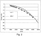
- Fig. 2
- shows schematically and exemplarily a diagram of a braking force generated by a typical 2 liters internal combustion engine according to the disclosure.
-
Fig. 1 shows a schematic view of an exemplary embodiment of a method for braking a hybrid electric vehicle according to the disclosure. The hybrid electric vehicle comprises a brake system, an electric motor and a battery system. In the hybrid electric vehicle, braking the vehicle can be performed by operating the electric motor as a generator, in which a brake energy produced during a brake event can be converted into electricity and the battery system can be charged with the regenerated brake energy. However, if a state of charge of the battery system is full, the battery cannot be charged anymore, thus the electric motor stops regenerating the brake energy. Instead, the vehicle is slowed or stopped by a brake disc of the brake system, which may cause an overheating of the brake system, particularly during driving in a downhill direction. - The hybrid electric vehicle in a series mode comprises no mechanical connection between wheels and an internal combustion engine of the vehicle. Hence, if a state of charge of the battery system full, a conventional engine braking, which may avoid an overheating of the brake system, is not possible.
- If the vehicle identifies S1 a need of braking such as driving in the downhill direction, the brake system actuates braking S2. The electric motor starts to regenerate S3 a brake energy received from the brake system. The regeneration of the brake energy may be performed by rotating the electric motor in a generator mode, in which the brake energy is converted into electricity.
- The control system receives S4 simultaneously a state of charge of the battery system, whether it has an enough capacity for charging or not. If the battery system has a free charging capacity, which means the state of charge is not 100%, the battery system is charged with the produced electricity S41. In case of a full charging of the battery system or whenever the battery system does not allow charging of all brake energy, however, the regenerated brake energy is redirected S5 to an integrated starter generator (ISG). Accordingly, the ISG is activated S6 and the internal combustion engine (ICE) can be rotated by the ISG.
- Once the ICE starts, a throttle inside the ICE is opened S7 to avoid an insertion of oil and/or exhaust gas residuals in the internal combustion engine. Accordingly, an entrance of the oil and/or exhaust gas residuals is blocked S8 and only air may be fed into a cylinder of the ICE. Additionally, the variable valve timing is appropriately set S9 to adjust an amount of an air intake in the cylinder and an amount of an air exhaust out of the cylinder of the ICE. The variable valve timing may influence an engine performance significantly and a brake energy absorption by the ICE can be maximized.
- Further, a speed of the ICE is varied S10 to control a braking force. The speed of the ICE may be adapted to the variable valve timing. By increasing the speed of the ICE, for example, the integrated starter generator may require higher regenerated brake energy to support the ICE. In other words, a braking force is dependent of the performance of the ICE.
- As shown in
Fig. 2 , the braking force increases as the performance of the ICE increases. The braking force may reach, hence, up to 40 kW in a typical 2 liters engine, which corresponds to a downhill slop of 20 % with a 2000 kg vehicle. The upper curve with thereference number 1 shows an increasing braking force with a fully opened throttle and the lower curve with thereference number 2 shows an increasing braking force with a nearly closed throttle. Accordingly, the opened throttle may not only prevent an insertion of oil and/or exhaust gas residuals into the ICE but also result in the best braking force. - The heat energy generated in the ICE by the air may be transferred to a coolant water, which circulates between a radiator system and the ICE. The coolant water with the heat energy is transported S11 to a conventional radiator system of the vehicle via a heat exchanger. The heat energy is then transferred S12 in the conventional radiator system to an ambient air. Accordingly, the excessive brake energy can be continuously regenerated and dissipated in the ambient air in form of the heat energy. Moreover, the brake system may be prevented from an overheating.
- It has to be noted that embodiments of the disclosure are described with reference to different subject matters. In particular, some embodiments are described with reference to method type claims whereas other embodiments are described with reference to the device type claims. However, a person skilled in the art will gather from the above and the following description that, unless otherwise notified, in addition to any combination of features belonging to one type of subject matter also any combination between features relating to different subject matters is considered to be disclosed with this application. However, all features can be combined providing synergetic effects that are more than the simple summation of the features.
- While the disclosure has been illustrated and described in detail in the drawings and description, such illustration and description are to be considered illustrative or exemplary and not restrictive. The disclosure is not limited to the disclosed embodiments. Other variations to the disclosed embodiments can be understood and effected by those skilled in the art in practicing a claimed disclosure, from a study of the drawings, the disclosure, and the dependent claims.
- In the claims, the word "comprising" does not exclude other elements or steps, and the indefinite article "a" or "an" does not exclude a plurality. A single processor or other unit may fulfil the functions of several items re-cited in the claims. The mere fact that certain measures are re-cited in mutually different dependent claims does not indicate that a combination of these measures cannot be used to advantage. Any reference signs in the claims should not be construed as limiting the scope.
Claims (12)
- A method for braking a hybrid electric vehicle, comprising:- actuating (S2) braking with a brake energy,- starting (S3) to regenerate the brake energy and charging a battery system with the regenerated brake energy,- receiving (S4) a state of charge of the battery system,- in case of a full or limited charging of the battery system, redirecting (S5) the regenerated brake energy into an integrated starter generator, and- activating (S6) the integrated starter generator to rotate an internal combustion engine.
- The method according to claim 1, further comprising reducing (S8) oil and/or exhaust gas residuals entering into the internal combustion engine.
- The method according to claim 1 or 2, further comprising opening (S7) a throttle to avoid an insertion of the oil and/or exhaust gas residuals in the internal combustion engine.
- The method according to claim 1, the brake energy being regenerated by an electric motor.
- The method according to any of the preceding claims, further comprising identifying (S1) a downhill driving direction.
- The method according to any of the preceding claims, further comprising transferring (S12) a heat energy generated in the internal combustion engine to an ambient air.
- The method according to the preceding claim, the heat energy being transferred (S11) to the ambient air by means of a conventional radiator system via a heat exchanger.
- The method according to any of the preceding claims, further comprising setting (S9) a variable valve timing of an air intake and/or an exhaust.
- The method according to any of the preceding claims, further comprising varying (S10) a speed of the internal combustion engine to control a braking force.
- A hybrid electric vehicle comprising an integrated starter generator, an internal combustion engine, a battery system and a control system,
the control system being configured to- actuate braking with a brake energy,- start to regenerate the brake energy and charge the battery system with the regenerated brake energy,- receive a state of charge of the battery system,- redirect the regenerated brake energy into the integrated starter generator in case of a full or limited charging of the battery system, and- activate the integrated starter generator to rotate the internal combustion engine. - The hybrid electric vehicle according to claim 10, comprising a series hybrid mode.
- A computer program element for braking a hybrid electric vehicle according to one of claims 10 and 11, which, when being executed by a processing element, is adapted to perform the method steps of the method claims 1 to 9.
Priority Applications (3)
| Application Number | Priority Date | Filing Date | Title |
|---|---|---|---|
| EP20215017.3A EP4015327A1 (en) | 2020-12-17 | 2020-12-17 | Method for braking a hybrid electric vehicle |
| US17/543,897 US12030498B2 (en) | 2020-12-17 | 2021-12-07 | Method for braking a hybrid electric vehicle |
| CN202111534077.3A CN114643871A (en) | 2020-12-17 | 2021-12-15 | Method for braking a hybrid electric vehicle |
Applications Claiming Priority (1)
| Application Number | Priority Date | Filing Date | Title |
|---|---|---|---|
| EP20215017.3A EP4015327A1 (en) | 2020-12-17 | 2020-12-17 | Method for braking a hybrid electric vehicle |
Publications (1)
| Publication Number | Publication Date |
|---|---|
| EP4015327A1 true EP4015327A1 (en) | 2022-06-22 |
Family
ID=73855346
Family Applications (1)
| Application Number | Title | Priority Date | Filing Date |
|---|---|---|---|
| EP20215017.3A Withdrawn EP4015327A1 (en) | 2020-12-17 | 2020-12-17 | Method for braking a hybrid electric vehicle |
Country Status (3)
| Country | Link |
|---|---|
| US (1) | US12030498B2 (en) |
| EP (1) | EP4015327A1 (en) |
| CN (1) | CN114643871A (en) |
Citations (4)
| Publication number | Priority date | Publication date | Assignee | Title |
|---|---|---|---|---|
| DE4446485A1 (en) * | 1994-12-23 | 1996-06-27 | Daimler Benz Ag | Method of braking hybrid drive motor vehicle |
| GB2450234A (en) * | 2007-06-20 | 2008-12-17 | Ford Global Tech Llc | Method of braking a vehicle using first and second electric energy conversion devices |
| EP2460679A1 (en) * | 2010-12-02 | 2012-06-06 | Jaguar Cars Ltd | Hybrid electric vehicle and method of control thereof |
| EP2896543A1 (en) * | 2012-09-11 | 2015-07-22 | Honda Motor Co., Ltd. | Hybrid vehicle |
Family Cites Families (10)
| Publication number | Priority date | Publication date | Assignee | Title |
|---|---|---|---|---|
| US6155365A (en) * | 1998-05-12 | 2000-12-05 | Chrysler Corporation | Brake blending strategy for a hybrid vehicle |
| US20050151420A1 (en) * | 2001-05-07 | 2005-07-14 | Dale Crombez | Hybrid electric vehicle powertrain with regenerative braking |
| US20100044129A1 (en) * | 2004-08-09 | 2010-02-25 | Hybrid Electric Conversion Co., Llc | Hybrid vehicle formed by converting a conventional ic engine powered vehicle and method of such conversion |
| JP4254762B2 (en) * | 2005-08-25 | 2009-04-15 | トヨタ自動車株式会社 | Power output apparatus, automobile equipped with the same, and control method of power output apparatus |
| US8958933B2 (en) * | 2012-01-19 | 2015-02-17 | Ford Global Technologies, Llc | Engine control system |
| GB2517470B (en) * | 2013-08-21 | 2016-07-20 | Jaguar Land Rover Ltd | Hybrid electric vehicle controller and method |
| KR101534731B1 (en) * | 2013-12-26 | 2015-07-27 | 현대자동차 주식회사 | Regenerative Brake Apparatus of Hybrid Vehicle and Method Thereof |
| CN107107764B (en) * | 2014-12-15 | 2020-08-14 | 沃尔沃卡车集团 | Method and device for charging an electrical energy storage system in a vehicle |
| US9975436B2 (en) * | 2015-09-12 | 2018-05-22 | GM Global Technology Operations LLC | Regeneration strategy for a vehicle having decoupled front and rear axle drive actuators |
| US10118605B2 (en) * | 2017-03-13 | 2018-11-06 | Ford Global Technologies, Llc | Methods and system for a hybrid vehicle |
-
2020
- 2020-12-17 EP EP20215017.3A patent/EP4015327A1/en not_active Withdrawn
-
2021
- 2021-12-07 US US17/543,897 patent/US12030498B2/en active Active
- 2021-12-15 CN CN202111534077.3A patent/CN114643871A/en active Pending
Patent Citations (5)
| Publication number | Priority date | Publication date | Assignee | Title |
|---|---|---|---|---|
| DE4446485A1 (en) * | 1994-12-23 | 1996-06-27 | Daimler Benz Ag | Method of braking hybrid drive motor vehicle |
| DE4446485C2 (en) * | 1994-12-23 | 2003-06-26 | Daimler Chrysler Ag | Method and device for braking a motor vehicle with hybrid drive |
| GB2450234A (en) * | 2007-06-20 | 2008-12-17 | Ford Global Tech Llc | Method of braking a vehicle using first and second electric energy conversion devices |
| EP2460679A1 (en) * | 2010-12-02 | 2012-06-06 | Jaguar Cars Ltd | Hybrid electric vehicle and method of control thereof |
| EP2896543A1 (en) * | 2012-09-11 | 2015-07-22 | Honda Motor Co., Ltd. | Hybrid vehicle |
Also Published As
| Publication number | Publication date |
|---|---|
| US12030498B2 (en) | 2024-07-09 |
| US20220194380A1 (en) | 2022-06-23 |
| CN114643871A (en) | 2022-06-21 |
Similar Documents
| Publication | Publication Date | Title |
|---|---|---|
| US7490685B2 (en) | Hybrid vehicle | |
| US7681547B2 (en) | Method for reducing torque required to crank engine in hybrid vehicle | |
| JP3581929B2 (en) | Engine operation control device for hybrid electric vehicle | |
| US6886649B2 (en) | Control device for hybrid vehicles | |
| CN107178452B (en) | System and method for starting an engine based on engine stop position | |
| US20090271057A1 (en) | Hybrid Vehicle Vibration Reduction System and Method | |
| US8972154B2 (en) | Engine stop determination device and engine stop determination method | |
| KR102358852B1 (en) | Coasting regeneration control method and device of CVVD engine with MHEV | |
| JP2012116474A (en) | Hybrid electric vehicle and method of control | |
| CN110425034A (en) | Method and system for engine control | |
| JP2016117451A (en) | Vehicle control device | |
| JP3679228B2 (en) | Method and apparatus for stopping engine of hybrid vehicle | |
| US12030498B2 (en) | Method for braking a hybrid electric vehicle | |
| JP2001309504A (en) | Control device for hybrid vehicle | |
| JP5696784B2 (en) | vehicle | |
| JP6091169B2 (en) | Vehicle control device | |
| JP7139073B2 (en) | Hybrid vehicle control device | |
| JP5282830B2 (en) | Electric drive vehicle | |
| JP7407550B2 (en) | Hybrid vehicle control device | |
| KR20230020286A (en) | Method for controlling powertrain of hybrid vehicle | |
| JP6973934B2 (en) | Vehicle heating system | |
| CN115123186A (en) | Vehicle control device | |
| JP2004068789A (en) | Automotive engine system | |
| JP7408256B2 (en) | Control device | |
| JPH11289608A (en) | Control device for hybrid vehicle |
Legal Events
| Date | Code | Title | Description |
|---|---|---|---|
| PUAI | Public reference made under article 153(3) epc to a published international application that has entered the european phase |
Free format text: ORIGINAL CODE: 0009012 |
|
| STAA | Information on the status of an ep patent application or granted ep patent |
Free format text: STATUS: REQUEST FOR EXAMINATION WAS MADE |
|
| 17P | Request for examination filed |
Effective date: 20211028 |
|
| AK | Designated contracting states |
Kind code of ref document: A1 Designated state(s): AL AT BE BG CH CY CZ DE DK EE ES FI FR GB GR HR HU IE IS IT LI LT LU LV MC MK MT NL NO PL PT RO RS SE SI SK SM TR |
|
| STAA | Information on the status of an ep patent application or granted ep patent |
Free format text: STATUS: EXAMINATION IS IN PROGRESS |
|
| 17Q | First examination report despatched |
Effective date: 20230306 |
|
| STAA | Information on the status of an ep patent application or granted ep patent |
Free format text: STATUS: THE APPLICATION HAS BEEN WITHDRAWN |
|
| 18W | Application withdrawn |
Effective date: 20230707 |