EP4015234A1 - Heat shield assembly for vehicle wheel - Google Patents
Heat shield assembly for vehicle wheel Download PDFInfo
- Publication number
- EP4015234A1 EP4015234A1 EP20461596.7A EP20461596A EP4015234A1 EP 4015234 A1 EP4015234 A1 EP 4015234A1 EP 20461596 A EP20461596 A EP 20461596A EP 4015234 A1 EP4015234 A1 EP 4015234A1
- Authority
- EP
- European Patent Office
- Prior art keywords
- heat shield
- plate
- wheel
- stress reduction
- assembly
- Prior art date
- Legal status (The legal status is an assumption and is not a legal conclusion. Google has not performed a legal analysis and makes no representation as to the accuracy of the status listed.)
- Withdrawn
Links
- 239000000463 material Substances 0.000 claims abstract description 21
- 238000000034 method Methods 0.000 claims description 7
- 238000003466 welding Methods 0.000 claims description 5
- 239000002356 single layer Substances 0.000 description 3
- 238000004458 analytical method Methods 0.000 description 2
- 238000009826 distribution Methods 0.000 description 2
- 230000002411 adverse Effects 0.000 description 1
- 230000000712 assembly Effects 0.000 description 1
- 238000000429 assembly Methods 0.000 description 1
- 238000005336 cracking Methods 0.000 description 1
- 230000000694 effects Effects 0.000 description 1
- 239000003779 heat-resistant material Substances 0.000 description 1
- 238000009434 installation Methods 0.000 description 1
- 238000004519 manufacturing process Methods 0.000 description 1
- 239000002184 metal Substances 0.000 description 1
- 238000005096 rolling process Methods 0.000 description 1
Images



Classifications
-
- B—PERFORMING OPERATIONS; TRANSPORTING
- B60—VEHICLES IN GENERAL
- B60B—VEHICLE WHEELS; CASTORS; AXLES FOR WHEELS OR CASTORS; INCREASING WHEEL ADHESION
- B60B7/00—Wheel cover discs, rings, or the like, for ornamenting, protecting, venting, or obscuring, wholly or in part, the wheel body, rim, hub, or tyre sidewall, e.g. wheel cover discs, wheel cover discs with cooling fins
- B60B7/0093—Wheel cover discs, rings, or the like, for ornamenting, protecting, venting, or obscuring, wholly or in part, the wheel body, rim, hub, or tyre sidewall, e.g. wheel cover discs, wheel cover discs with cooling fins being reinforced against thermal deformation
-
- B—PERFORMING OPERATIONS; TRANSPORTING
- B60—VEHICLES IN GENERAL
- B60B—VEHICLE WHEELS; CASTORS; AXLES FOR WHEELS OR CASTORS; INCREASING WHEEL ADHESION
- B60B7/00—Wheel cover discs, rings, or the like, for ornamenting, protecting, venting, or obscuring, wholly or in part, the wheel body, rim, hub, or tyre sidewall, e.g. wheel cover discs, wheel cover discs with cooling fins
- B60B7/06—Fastening arrangements therefor
- B60B7/14—Fastening arrangements therefor comprising screw-threaded means
-
- B—PERFORMING OPERATIONS; TRANSPORTING
- B60—VEHICLES IN GENERAL
- B60B—VEHICLE WHEELS; CASTORS; AXLES FOR WHEELS OR CASTORS; INCREASING WHEEL ADHESION
- B60B7/00—Wheel cover discs, rings, or the like, for ornamenting, protecting, venting, or obscuring, wholly or in part, the wheel body, rim, hub, or tyre sidewall, e.g. wheel cover discs, wheel cover discs with cooling fins
- B60B7/04—Wheel cover discs, rings, or the like, for ornamenting, protecting, venting, or obscuring, wholly or in part, the wheel body, rim, hub, or tyre sidewall, e.g. wheel cover discs, wheel cover discs with cooling fins built-up of several main parts
-
- B—PERFORMING OPERATIONS; TRANSPORTING
- B60—VEHICLES IN GENERAL
- B60B—VEHICLE WHEELS; CASTORS; AXLES FOR WHEELS OR CASTORS; INCREASING WHEEL ADHESION
- B60B7/00—Wheel cover discs, rings, or the like, for ornamenting, protecting, venting, or obscuring, wholly or in part, the wheel body, rim, hub, or tyre sidewall, e.g. wheel cover discs, wheel cover discs with cooling fins
- B60B7/06—Fastening arrangements therefor
- B60B7/061—Fastening arrangements therefor characterised by the part of the wheels to which the discs, rings or the like are mounted
- B60B7/063—Fastening arrangements therefor characterised by the part of the wheels to which the discs, rings or the like are mounted to the rim
-
- B—PERFORMING OPERATIONS; TRANSPORTING
- B60—VEHICLES IN GENERAL
- B60C—VEHICLE TYRES; TYRE INFLATION; TYRE CHANGING; CONNECTING VALVES TO INFLATABLE ELASTIC BODIES IN GENERAL; DEVICES OR ARRANGEMENTS RELATED TO TYRES
- B60C23/00—Devices for measuring, signalling, controlling, or distributing tyre pressure or temperature, specially adapted for mounting on vehicles; Arrangement of tyre inflating devices on vehicles, e.g. of pumps or of tanks; Tyre cooling arrangements
- B60C23/18—Tyre cooling arrangements, e.g. heat shields
- B60C23/19—Tyre cooling arrangements, e.g. heat shields for dissipating heat
-
- B—PERFORMING OPERATIONS; TRANSPORTING
- B60—VEHICLES IN GENERAL
- B60B—VEHICLE WHEELS; CASTORS; AXLES FOR WHEELS OR CASTORS; INCREASING WHEEL ADHESION
- B60B2310/00—Manufacturing methods
- B60B2310/30—Manufacturing methods joining
- B60B2310/302—Manufacturing methods joining by welding
-
- B—PERFORMING OPERATIONS; TRANSPORTING
- B60—VEHICLES IN GENERAL
- B60B—VEHICLE WHEELS; CASTORS; AXLES FOR WHEELS OR CASTORS; INCREASING WHEEL ADHESION
- B60B2900/00—Purpose of invention
- B60B2900/20—Avoidance of
- B60B2900/212—Damage
-
- F—MECHANICAL ENGINEERING; LIGHTING; HEATING; WEAPONS; BLASTING
- F16—ENGINEERING ELEMENTS AND UNITS; GENERAL MEASURES FOR PRODUCING AND MAINTAINING EFFECTIVE FUNCTIONING OF MACHINES OR INSTALLATIONS; THERMAL INSULATION IN GENERAL
- F16D—COUPLINGS FOR TRANSMITTING ROTATION; CLUTCHES; BRAKES
- F16D65/00—Parts or details
- F16D65/78—Features relating to cooling
- F16D2065/785—Heat insulation or reflection
Definitions
- the present disclosure is concerned with a heat shield assembly for a vehicle wheel such as, but not exclusively, an aircraft wheel.
- Vehicle wheels often have to rotate very quickly and may also be used in extreme environments where they are subject to very high temperatures. For example, friction generated when braking a wheel can cause the wheel material to become extremely hot which can cause damage to the wheel or otherwise adversely affect its operation. The very high braking forces on aircraft wheels, in particular, generate very high temperatures.
- the heat shield is usually a plate of more heat resistant material attached to the wheel by several bolts or rivets.
- the bolts or rivets are secured through holes in the heat shield and wheel structure. Heat tends to be conducted through these holes and the holes provide areas of weakness. Further, the high rotational velocity of the wheel (centrifugal load) and the tyre pressure (due to rolling of the wheel) cause large deflection of the heat shield and high stresses at the attachment holes, thus leading to cracking of the heat shield near the attachment holes.
- a heat shield assembly complying a plate of heat shield material having an attachment hole therein by means of which the plate can be attached to another part using a fixation means, the assembly further comprising a stress reduction plate secured to the plate of heat shield material at a plurality of securing points spaced from the attachment hole.
- the stress reduction plate is secured to the plate of heat shield material by e.g. welding.
- the securing points are at the outer edge of the stress reduction plate.
- Test have been carried out with four securing points and with nine securing points as examples.
- the plate of heat shield material has two or more attachment holes and a stress reduction plate is secured to the plate around each attachment hole.
- the heat shield will comprise a plurality of plates of heat shield material, each having one or more attachment holes and one or more stress reduction plate.
- the wheel is an aircraft wheel.
- a method of forming a heat shield for attachment to a part comprising securing a stress reduction plate, at a plurality of securing points, around an attachment hole in a plate of heat shield material to be attached, via the attachment hole, to a part.
- the present disclosure provides a solution to the problems mentioned above due to the areas around the heat shield attachment holes providing a weak point for structural damage.
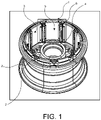
- Fig. 1 shows a wheel hub 1 having an outer surface 2 around which a tyre would usually be mounted (not shown here, for simplicity) and an inner surface 3.
- the wheel axis 4 is defined at the centre of the wheel by means of which the wheel is mounted to a shaft of the aircraft etc. and around which the wheel rotates in use.
- Fig. 1 shows heat shield segments 5 mounted around the inner surface 3 of the wheel.
- the heat shield segments are plates of metal and these are mounted to the wheel using fasteners such as bolts 6 which are fastened through holes 7 to secure the heat shield to the wheel.
- the attachment holes are shown in close-up in Fig. 2 .
- the heat shield is divided into nine segments 5, and each heat shield segment is attached by screws or bolts at two holes at the top of the heat shield. This is just one example and any other number of, and positioning of segments and attachment holes can be provided.
- the present arrangement provides a heat shield stress reduction plate 8 which is provide as an additional, single layer of heat shield plate material to the heat shield in the region around the attachment hole 7.
- the additional plate 8 is secured to the inner surface of the heat shield segment 5 only in the region around the attachment hole 7 and so is smaller than the heat shield plate.
- the stress reduction plate 8 should be as small as possible to achieve the desired stress reduction around the holes whilst minimising the additional weight and cost of the assembly.
- a stress reduction plate 8 is provided around each heat shield attachment hole 7.
- each weld point can have a smaller diameter than arrangements where there are fewer weld points, but this does not have to be the case. Any other number of weld points can be provided but the aim of the designer will usually be to ensure secure attachment and optimal stress distribution whilst minimising weight and cost.
- the shape and size of the plate and the number and locations of weld points will ideally be determined based on FEA calculations.
- the stress reduction plate 8 can be made of the same or a different material. Using the same material will minimise costs. Most preferably, the stress reduction plate 8 is a single layer thickness of the heat shield material mounted onto the heat shield around the attachment holes.
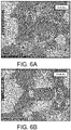
- Figs. 6A and 6B show a comparison of the stress maps for the four weld point and the nine weld point embodiments.
- the stress reduction plate By applying a stress reduction plate around the heat shield attachment hole, the stress created at the hole is better distributed over the whole stress reduction plate and this avoids dangerous yield points at the attachment holes.
- the stress reduction plate is simple and inexpensive to manufacture and to install and by providing the plate as just a single layer thickness, it does not add considerably to the wheel weight and does not cause collisions with other parts during attachment or operation.
Landscapes
- Engineering & Computer Science (AREA)
- Mechanical Engineering (AREA)
- Connection Of Plates (AREA)
Abstract
Description
- The present disclosure is concerned with a heat shield assembly for a vehicle wheel such as, but not exclusively, an aircraft wheel.
- Vehicle wheels often have to rotate very quickly and may also be used in extreme environments where they are subject to very high temperatures. For example, friction generated when braking a wheel can cause the wheel material to become extremely hot which can cause damage to the wheel or otherwise adversely affect its operation. The very high braking forces on aircraft wheels, in particular, generate very high temperatures.
- One way of protecting wheels against the effects of such high temperatures is to provide a heat shield on the wheel structure. The heat shield is usually a plate of more heat resistant material attached to the wheel by several bolts or rivets. The bolts or rivets are secured through holes in the heat shield and wheel structure. Heat tends to be conducted through these holes and the holes provide areas of weakness. Further, the high rotational velocity of the wheel (centrifugal load) and the tyre pressure (due to rolling of the wheel) cause large deflection of the heat shield and high stresses at the attachment holes, thus leading to cracking of the heat shield near the attachment holes.
- If the heat shield is damaged in this way, its life is reduced and there is a risk of the heatshield breaking away during operation or at least of the heat shield not properly protecting the wheel structure from the high temperature environment.
- There is, therefore, a need for an improved heat shield structure to overcome these problems.
- According to one aspect, there is provided a heat shield assembly complying a plate of heat shield material having an attachment hole therein by means of which the plate can be attached to another part using a fixation means, the assembly further comprising a stress reduction plate secured to the plate of heat shield material at a plurality of securing points spaced from the attachment hole.
- The stress reduction plate is secured to the plate of heat shield material by e.g. welding.
- Ideally, the securing points are at the outer edge of the stress reduction plate.
- Test have been carried out with four securing points and with nine securing points as examples.
- In the examples, the plate of heat shield material has two or more attachment holes and a stress reduction plate is secured to the plate around each attachment hole.
- Usually, the heat shield will comprise a plurality of plates of heat shield material, each having one or more attachment holes and one or more stress reduction plate.
- Also provided is a wheel to which such a heat shield assembly is attached. In one example, the wheel is an aircraft wheel.
- According to another aspect, there is provided a method of forming a heat shield for attachment to a part, the method comprising securing a stress reduction plate, at a plurality of securing points, around an attachment hole in a plate of heat shield material to be attached, via the attachment hole, to a part.
- Preferred embodiments of the disclosure will now be described by way of example only and with reference to the drawings. Although reference may be made to aircraft wheels, the disclosure is not limited to aircraft wheels but also includes other wheel arrangements in vehicles, machinery or anywhere where the wheel can be subjected to potentially damaging high temperatures.
-
-
Figure 1 shows a perspective view of a wheel to which a heat shield is attached. -
Figure 2 shows a detail ofFig. 1 showing bolt holes to which a heat shield is attached in a conventional installation. -
Fig. 3 shows an example of a heat shield assembly attached to a wheel in accordance with this disclosure. -
Fig. 4 shows an alternative example of a heat shield assembly attached to a wheel in accordance with this disclosure. -
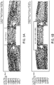
Figs. 5A, 5B and5C compare stress maps from a finite element analysis for a conventional design (Fig. 5A ), a design such as shown inFig. 3 (Fig. 5B ) and a design such as shown inFig. 4 (Fig. 5C ). -
Figs. 6A and 6B provide a closer view of the stress maps ofFigs. 5B and 5B for comparison - The present disclosure provides a solution to the problems mentioned above due to the areas around the heat shield attachment holes providing a weak point for structural damage.
- Referring first to
Figs. 1 and2 ,Fig. 1 shows awheel hub 1 having anouter surface 2 around which a tyre would usually be mounted (not shown here, for simplicity) and aninner surface 3. Thewheel axis 4 is defined at the centre of the wheel by means of which the wheel is mounted to a shaft of the aircraft etc. and around which the wheel rotates in use. - As discussed above, wheels are generally provided with heat shields.
Fig. 1 showsheat shield segments 5 mounted around theinner surface 3 of the wheel. The heat shield segments are plates of metal and these are mounted to the wheel using fasteners such asbolts 6 which are fastened throughholes 7 to secure the heat shield to the wheel. The attachment holes are shown in close-up inFig. 2 . In the example shown, the heat shield is divided into ninesegments 5, and each heat shield segment is attached by screws or bolts at two holes at the top of the heat shield. This is just one example and any other number of, and positioning of segments and attachment holes can be provided. - As mentioned above, these attachment holes cause areas of weakness, where, for example, the heat shield can crack.
- The present arrangement provides a heat shield
stress reduction plate 8 which is provide as an additional, single layer of heat shield plate material to the heat shield in the region around theattachment hole 7. Theadditional plate 8 is secured to the inner surface of theheat shield segment 5 only in the region around theattachment hole 7 and so is smaller than the heat shield plate. Thestress reduction plate 8 should be as small as possible to achieve the desired stress reduction around the holes whilst minimising the additional weight and cost of the assembly. - In the example shown, a
stress reduction plate 8 is provided around each heatshield attachment hole 7. - The
plate 8 is secured to the heat shield by means of e.g. welding atweld points 9. Ideally, these points are spaced as far away from theattachment hole 7 on the stress reduction plate in order to better distribute the load. Ideally, the weld points are around the perimeter of theplate 8. Having the weld points too close to the holes could create excessive stress. There should be an area between the attachment hole and the weld points for better distribution of stress.Fig. 3 shows one example of astress reduction plate 8 with fourweld points 9.Fig. 4 shows an alternative arrangement where the stress reduction plate 8' is attached to the heat shield at nine weld points 9'. Where more weld points are provided, each weld point can have a smaller diameter than arrangements where there are fewer weld points, but this does not have to be the case. Any other number of weld points can be provided but the aim of the designer will usually be to ensure secure attachment and optimal stress distribution whilst minimising weight and cost. - The shape and size of the plate and the number and locations of weld points will ideally be determined based on FEA calculations.
- Various materials can be used, as is known in the art, for the
heat shield 5. Thestress reduction plate 8 can be made of the same or a different material. Using the same material will minimise costs. Most preferably, thestress reduction plate 8 is a single layer thickness of the heat shield material mounted onto the heat shield around the attachment holes. - The results of the finite element analysis (FEA) of heat shield assemblies with, respectively, no additional stress reduction plate, a stress reduction plate secured at four weld points, and a stress reduction plate secured at nine weld points, are shown in
Figs 5A, 5B and5C . It can be seen from these results that where there is no stress reduction plate, inFig. 5A , there are areas of particularly high stress around the attachment holes 7. The stress at these points reduces, and the stress is more spread out, when the stress reduction plate is attached with four weld point (Fig. 5B ). The improvement is slightly less when the stress reduction plate is attached at nine weld points (Fig. 5C ), but there is still a noticeable reduction of stress around the holes. -
Figs. 6A and 6B show a comparison of the stress maps for the four weld point and the nine weld point embodiments. - To assemble the heat shield assembly in a simple manner, the stress reduction plate can be first attached to the heat shield plate or segment around the
attachment hole 7 in theheat shield plate 5 by e.g. welding at the desired weld points. The assembly of heat shield segment and stress reduction plate is then mounted to the wheel in the same way the heat shield segment would normally be mounted to the wheel and is secured by screws or bolts at the attachment hole. - By applying a stress reduction plate around the heat shield attachment hole, the stress created at the hole is better distributed over the whole stress reduction plate and this avoids dangerous yield points at the attachment holes. The stress reduction plate is simple and inexpensive to manufacture and to install and by providing the plate as just a single layer thickness, it does not add considerably to the wheel weight and does not cause collisions with other parts during attachment or operation.
Claims (14)
- A heat shield assembly complying a plate (5) of heat shield material having an attachment hole (7) therein by means of which the plate can be attached to another part using a fixation means, the assembly further comprising a stress reduction plate (8) secured to the plate (5) of heat shield material at a plurality of securing points (9) spaced from the attachment hole (7).
- The assembly of claim 1, whereby the stress reduction plate (8) is secured to the plate (5) of heat shield material by welding.
- The assembly of any preceding claim, whereby the plurality of securing points (9) are at the outer edge of the stress reduction plate (8).
- The assembly of any preceding claim, having four securing points (9).
- The assembly of any preceding claim, having nine securing points (9').
- The assembly of any preceding claim, wherein the plate (5) of heat shield material has two or more attachment holes (7) and a stress reduction plate (8) secured to the plate (5) around each attachment hole (7).
- The assembly of any preceding claim, comprising a plurality of plates (5) of heat shield material, each having one or more attachment holes (7) and one or more stress reduction plate (8).
- A wheel to which a heat shield assembly according to any preceding claim is attached.
- The wheel of claim 8, wherein the heat shield assembly is attached by screws or bolts through the attachment hole(s) (7).
- The wheel of claim 8 or 9, being an aircraft wheel.
- A method of forming a heat shield for attachment to a part, the method comprising securing a stress reduction plate, at a plurality of securing points, around an attachment hole in a plate of heat shield material to be attached, via the attachment hole, to a part.
- The method of claim 11, wherein the securing is by means of welding.
- The method of claim 11 or 12, further comprising securing the heat shield material to which the stress reduction plate is secured, to the part by means of fixation means.
- The method of claim 13, whereby the fixation means are screws or bolts.
Priority Applications (2)
| Application Number | Priority Date | Filing Date | Title |
|---|---|---|---|
| EP20461596.7A EP4015234A1 (en) | 2020-12-15 | 2020-12-15 | Heat shield assembly for vehicle wheel |
| US17/541,359 US20220185010A1 (en) | 2020-12-15 | 2021-12-03 | Heat shield assembly for vehicle wheel |
Applications Claiming Priority (1)
| Application Number | Priority Date | Filing Date | Title |
|---|---|---|---|
| EP20461596.7A EP4015234A1 (en) | 2020-12-15 | 2020-12-15 | Heat shield assembly for vehicle wheel |
Publications (1)
| Publication Number | Publication Date |
|---|---|
| EP4015234A1 true EP4015234A1 (en) | 2022-06-22 |
Family
ID=73854807
Family Applications (1)
| Application Number | Title | Priority Date | Filing Date |
|---|---|---|---|
| EP20461596.7A Withdrawn EP4015234A1 (en) | 2020-12-15 | 2020-12-15 | Heat shield assembly for vehicle wheel |
Country Status (2)
| Country | Link |
|---|---|
| US (1) | US20220185010A1 (en) |
| EP (1) | EP4015234A1 (en) |
Citations (3)
| Publication number | Priority date | Publication date | Assignee | Title |
|---|---|---|---|---|
| US5002342A (en) * | 1989-12-28 | 1991-03-26 | Aircraft Braking Systems Corporation | Brake assembly heat shield |
| WO1993002878A1 (en) * | 1991-08-07 | 1993-02-18 | Allied-Signal Inc. | Wheel assembly hinged heat shield |
| KR101214307B1 (en) * | 2011-12-14 | 2012-12-20 | 서성근 | Insulator device of tire wheel |
Family Cites Families (12)
| Publication number | Priority date | Publication date | Assignee | Title |
|---|---|---|---|---|
| US4017123A (en) * | 1976-04-02 | 1977-04-12 | The Bendix Corporation | Dual layer heat shield for wheels |
| US5107968A (en) * | 1991-02-12 | 1992-04-28 | The B. F. Goodrich Company | Heatshield for aircraft brake |
| US5199536A (en) * | 1992-02-13 | 1993-04-06 | The B. F. Goodrich Company | Heatshield installation for aircraft brake |
| JP3394318B2 (en) * | 1994-04-08 | 2003-04-07 | イビデン株式会社 | Three-dimensional sound and heat insulating plate |
| US7051845B2 (en) * | 2001-10-10 | 2006-05-30 | Goodrich Corporation | Heat shield assembly for aircraft wheel and brake assembly |
| EP1780057A3 (en) * | 2001-10-10 | 2007-05-16 | Goodrich Corporation | Heat shield assembly for an aircraft wheel and brake assembly |
| JP4453089B2 (en) * | 2007-10-01 | 2010-04-21 | 関東自動車工業株式会社 | Knee bracket |
| US8668276B2 (en) * | 2011-07-14 | 2014-03-11 | Meggitt Aircraft Braking Systems | Wheel assembly heat shield |
| US9908375B2 (en) * | 2015-10-20 | 2018-03-06 | Goodrich Corporation | Ventilated key-slot full circle heat shield |
| US10330163B2 (en) * | 2017-10-16 | 2019-06-25 | Goodrich Corporation | Shield attachment method and device |
| US11274715B2 (en) * | 2019-07-16 | 2022-03-15 | Goodrich Corporation | Heat shield retainer and methods |
| FR3109765B1 (en) * | 2020-05-04 | 2022-06-17 | Safran Landing Systems | Heat shield for braking device of an aircraft wheel |
-
2020
- 2020-12-15 EP EP20461596.7A patent/EP4015234A1/en not_active Withdrawn
-
2021
- 2021-12-03 US US17/541,359 patent/US20220185010A1/en not_active Abandoned
Patent Citations (3)
| Publication number | Priority date | Publication date | Assignee | Title |
|---|---|---|---|---|
| US5002342A (en) * | 1989-12-28 | 1991-03-26 | Aircraft Braking Systems Corporation | Brake assembly heat shield |
| WO1993002878A1 (en) * | 1991-08-07 | 1993-02-18 | Allied-Signal Inc. | Wheel assembly hinged heat shield |
| KR101214307B1 (en) * | 2011-12-14 | 2012-12-20 | 서성근 | Insulator device of tire wheel |
Also Published As
| Publication number | Publication date |
|---|---|
| US20220185010A1 (en) | 2022-06-16 |
Similar Documents
| Publication | Publication Date | Title |
|---|---|---|
| US7850251B1 (en) | Wheel hub and brake rotor assembly | |
| US9714685B2 (en) | Disk brake hub assembly | |
| EP3159571B1 (en) | Ventilated key-slot full circle heat shield | |
| KR101828637B1 (en) | Method for mounting shielding on a turbine casing, and mounting assembly for implementing same | |
| US20090218183A1 (en) | Brake rotor and abs tone ring attachment assembly that promotes in plane uniform torque transfer distribution | |
| US20160025165A1 (en) | Brake Disc Mounting Arrangement | |
| US20100322782A1 (en) | Nosecone bolt access and aerodynamic leakage baffle | |
| US20170074336A1 (en) | Disc brake assembly | |
| EP3910210B1 (en) | Brake rotor | |
| US11448081B2 (en) | Balanced circumferential seal | |
| US20160258500A1 (en) | Brake Disc Mounting Arrangement | |
| US20160298706A1 (en) | Floating Disc Brake Rotor Assemble and Method for Attaching Same | |
| US20120247884A1 (en) | Disk brake hub assembly | |
| US20220185010A1 (en) | Heat shield assembly for vehicle wheel | |
| US9566957B2 (en) | Disk brake hub assembly | |
| WO1992005369A1 (en) | Ablative brake bushing for axle thermal protection | |
| US20240270374A1 (en) | Heat shield assembly | |
| US12515476B2 (en) | Heat shield retainers and heat shield bumper placement | |
| WO2002028710A1 (en) | Elastomeric bearing | |
| CA1178901A (en) | Segmented flexible hub | |
| EP4155571B1 (en) | Heat shield panel attachment bracket | |
| US12415381B2 (en) | Heat shield retainers and bumper standoffs for heat shield retainers | |
| US4243269A (en) | Edge lugged tire carrying rim and wheels | |
| US20210317755A1 (en) | Bypass turbomachine | |
| US20230349436A1 (en) | Ventilation system for aircraft wheel and wheel assembly including such a system |
Legal Events
| Date | Code | Title | Description |
|---|---|---|---|
| PUAI | Public reference made under article 153(3) epc to a published international application that has entered the european phase |
Free format text: ORIGINAL CODE: 0009012 |
|
| STAA | Information on the status of an ep patent application or granted ep patent |
Free format text: STATUS: THE APPLICATION HAS BEEN PUBLISHED |
|
| AK | Designated contracting states |
Kind code of ref document: A1 Designated state(s): AL AT BE BG CH CY CZ DE DK EE ES FI FR GB GR HR HU IE IS IT LI LT LU LV MC MK MT NL NO PL PT RO RS SE SI SK SM TR |
|
| STAA | Information on the status of an ep patent application or granted ep patent |
Free format text: STATUS: REQUEST FOR EXAMINATION WAS MADE |
|
| 17P | Request for examination filed |
Effective date: 20221222 |
|
| RBV | Designated contracting states (corrected) |
Designated state(s): AL AT BE BG CH CY CZ DE DK EE ES FI FR GB GR HR HU IE IS IT LI LT LU LV MC MK MT NL NO PL PT RO RS SE SI SK SM TR |
|
| P01 | Opt-out of the competence of the unified patent court (upc) registered |
Effective date: 20230922 |
|
| STAA | Information on the status of an ep patent application or granted ep patent |
Free format text: STATUS: THE APPLICATION HAS BEEN WITHDRAWN |
|
| 18W | Application withdrawn |
Effective date: 20241022 |