EP4015199A1 - Demolding - Google Patents
Demolding Download PDFInfo
- Publication number
- EP4015199A1 EP4015199A1 EP21196383.0A EP21196383A EP4015199A1 EP 4015199 A1 EP4015199 A1 EP 4015199A1 EP 21196383 A EP21196383 A EP 21196383A EP 4015199 A1 EP4015199 A1 EP 4015199A1
- Authority
- EP
- European Patent Office
- Prior art keywords
- workpiece
- mandrel
- actuators
- forces
- couplers
- Prior art date
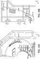
- Legal status (The legal status is an assumption and is not a legal conclusion. Google has not performed a legal analysis and makes no representation as to the accuracy of the status listed.)
- Granted
Links
Images






Classifications
-
- B—PERFORMING OPERATIONS; TRANSPORTING
- B29—WORKING OF PLASTICS; WORKING OF SUBSTANCES IN A PLASTIC STATE IN GENERAL
- B29C—SHAPING OR JOINING OF PLASTICS; SHAPING OF MATERIAL IN A PLASTIC STATE, NOT OTHERWISE PROVIDED FOR; AFTER-TREATMENT OF THE SHAPED PRODUCTS, e.g. REPAIRING
- B29C33/00—Moulds or cores; Details thereof or accessories therefor
- B29C33/44—Moulds or cores; Details thereof or accessories therefor with means for, or specially constructed to facilitate, the removal of articles, e.g. of undercut articles
-
- B—PERFORMING OPERATIONS; TRANSPORTING
- B29—WORKING OF PLASTICS; WORKING OF SUBSTANCES IN A PLASTIC STATE IN GENERAL
- B29C—SHAPING OR JOINING OF PLASTICS; SHAPING OF MATERIAL IN A PLASTIC STATE, NOT OTHERWISE PROVIDED FOR; AFTER-TREATMENT OF THE SHAPED PRODUCTS, e.g. REPAIRING
- B29C33/00—Moulds or cores; Details thereof or accessories therefor
- B29C33/44—Moulds or cores; Details thereof or accessories therefor with means for, or specially constructed to facilitate, the removal of articles, e.g. of undercut articles
- B29C33/48—Moulds or cores; Details thereof or accessories therefor with means for, or specially constructed to facilitate, the removal of articles, e.g. of undercut articles with means for collapsing or disassembling
- B29C33/485—Moulds or cores; Details thereof or accessories therefor with means for, or specially constructed to facilitate, the removal of articles, e.g. of undercut articles with means for collapsing or disassembling cores or mandrels
-
- B—PERFORMING OPERATIONS; TRANSPORTING
- B29—WORKING OF PLASTICS; WORKING OF SUBSTANCES IN A PLASTIC STATE IN GENERAL
- B29C—SHAPING OR JOINING OF PLASTICS; SHAPING OF MATERIAL IN A PLASTIC STATE, NOT OTHERWISE PROVIDED FOR; AFTER-TREATMENT OF THE SHAPED PRODUCTS, e.g. REPAIRING
- B29C70/00—Shaping composites, i.e. plastics material comprising reinforcements, fillers or preformed parts, e.g. inserts
- B29C70/04—Shaping composites, i.e. plastics material comprising reinforcements, fillers or preformed parts, e.g. inserts comprising reinforcements only, e.g. self-reinforcing plastics
- B29C70/28—Shaping operations therefor
- B29C70/54—Component parts, details or accessories; Auxiliary operations, e.g. feeding or storage of prepregs or SMC after impregnation or during ageing
- B29C70/545—Perforating, cutting or machining during or after moulding
-
- B—PERFORMING OPERATIONS; TRANSPORTING
- B29—WORKING OF PLASTICS; WORKING OF SUBSTANCES IN A PLASTIC STATE IN GENERAL
- B29C—SHAPING OR JOINING OF PLASTICS; SHAPING OF MATERIAL IN A PLASTIC STATE, NOT OTHERWISE PROVIDED FOR; AFTER-TREATMENT OF THE SHAPED PRODUCTS, e.g. REPAIRING
- B29C33/00—Moulds or cores; Details thereof or accessories therefor
- B29C33/12—Moulds or cores; Details thereof or accessories therefor with incorporated means for positioning inserts, e.g. labels
-
- B—PERFORMING OPERATIONS; TRANSPORTING
- B29—WORKING OF PLASTICS; WORKING OF SUBSTANCES IN A PLASTIC STATE IN GENERAL
- B29C—SHAPING OR JOINING OF PLASTICS; SHAPING OF MATERIAL IN A PLASTIC STATE, NOT OTHERWISE PROVIDED FOR; AFTER-TREATMENT OF THE SHAPED PRODUCTS, e.g. REPAIRING
- B29C37/00—Component parts, details, accessories or auxiliary operations, not covered by group B29C33/00 or B29C35/00
- B29C37/0003—Discharging moulded articles from the mould
-
- B—PERFORMING OPERATIONS; TRANSPORTING
- B29—WORKING OF PLASTICS; WORKING OF SUBSTANCES IN A PLASTIC STATE IN GENERAL
- B29C—SHAPING OR JOINING OF PLASTICS; SHAPING OF MATERIAL IN A PLASTIC STATE, NOT OTHERWISE PROVIDED FOR; AFTER-TREATMENT OF THE SHAPED PRODUCTS, e.g. REPAIRING
- B29C45/00—Injection moulding, i.e. forcing the required volume of moulding material through a nozzle into a closed mould; Apparatus therefor
- B29C45/17—Component parts, details or accessories; Auxiliary operations
- B29C45/40—Removing or ejecting moulded articles
-
- B—PERFORMING OPERATIONS; TRANSPORTING
- B29—WORKING OF PLASTICS; WORKING OF SUBSTANCES IN A PLASTIC STATE IN GENERAL
- B29C—SHAPING OR JOINING OF PLASTICS; SHAPING OF MATERIAL IN A PLASTIC STATE, NOT OTHERWISE PROVIDED FOR; AFTER-TREATMENT OF THE SHAPED PRODUCTS, e.g. REPAIRING
- B29C70/00—Shaping composites, i.e. plastics material comprising reinforcements, fillers or preformed parts, e.g. inserts
- B29C70/04—Shaping composites, i.e. plastics material comprising reinforcements, fillers or preformed parts, e.g. inserts comprising reinforcements only, e.g. self-reinforcing plastics
- B29C70/28—Shaping operations therefor
- B29C70/30—Shaping by lay-up, i.e. applying fibres, tape or broadsheet on a mould, former or core; Shaping by spray-up, i.e. spraying of fibres on a mould, former or core
- B29C70/32—Shaping by lay-up, i.e. applying fibres, tape or broadsheet on a mould, former or core; Shaping by spray-up, i.e. spraying of fibres on a mould, former or core on a rotating mould, former or core
-
- B—PERFORMING OPERATIONS; TRANSPORTING
- B29—WORKING OF PLASTICS; WORKING OF SUBSTANCES IN A PLASTIC STATE IN GENERAL
- B29C—SHAPING OR JOINING OF PLASTICS; SHAPING OF MATERIAL IN A PLASTIC STATE, NOT OTHERWISE PROVIDED FOR; AFTER-TREATMENT OF THE SHAPED PRODUCTS, e.g. REPAIRING
- B29C70/00—Shaping composites, i.e. plastics material comprising reinforcements, fillers or preformed parts, e.g. inserts
- B29C70/04—Shaping composites, i.e. plastics material comprising reinforcements, fillers or preformed parts, e.g. inserts comprising reinforcements only, e.g. self-reinforcing plastics
- B29C70/28—Shaping operations therefor
- B29C70/40—Shaping or impregnating by compression not applied
- B29C70/42—Shaping or impregnating by compression not applied for producing articles of definite length, i.e. discrete articles
- B29C70/46—Shaping or impregnating by compression not applied for producing articles of definite length, i.e. discrete articles using matched moulds, e.g. for deforming sheet moulding compounds [SMC] or prepregs
- B29C70/462—Moulding structures having an axis of symmetry or at least one channel, e.g. tubular structures, frames
-
- B—PERFORMING OPERATIONS; TRANSPORTING
- B29—WORKING OF PLASTICS; WORKING OF SUBSTANCES IN A PLASTIC STATE IN GENERAL
- B29C—SHAPING OR JOINING OF PLASTICS; SHAPING OF MATERIAL IN A PLASTIC STATE, NOT OTHERWISE PROVIDED FOR; AFTER-TREATMENT OF THE SHAPED PRODUCTS, e.g. REPAIRING
- B29C70/00—Shaping composites, i.e. plastics material comprising reinforcements, fillers or preformed parts, e.g. inserts
- B29C70/04—Shaping composites, i.e. plastics material comprising reinforcements, fillers or preformed parts, e.g. inserts comprising reinforcements only, e.g. self-reinforcing plastics
- B29C70/28—Shaping operations therefor
- B29C70/54—Component parts, details or accessories; Auxiliary operations, e.g. feeding or storage of prepregs or SMC after impregnation or during ageing
-
- B—PERFORMING OPERATIONS; TRANSPORTING
- B29—WORKING OF PLASTICS; WORKING OF SUBSTANCES IN A PLASTIC STATE IN GENERAL
- B29D—PRODUCING PARTICULAR ARTICLES FROM PLASTICS OR FROM SUBSTANCES IN A PLASTIC STATE
- B29D99/00—Subject matter not provided for in other groups of this subclass
- B29D99/001—Producing wall or panel-like structures, e.g. for hulls, fuselages, or buildings
-
- B—PERFORMING OPERATIONS; TRANSPORTING
- B29—WORKING OF PLASTICS; WORKING OF SUBSTANCES IN A PLASTIC STATE IN GENERAL
- B29D—PRODUCING PARTICULAR ARTICLES FROM PLASTICS OR FROM SUBSTANCES IN A PLASTIC STATE
- B29D99/00—Subject matter not provided for in other groups of this subclass
- B29D99/001—Producing wall or panel-like structures, e.g. for hulls, fuselages, or buildings
- B29D99/0014—Producing wall or panel-like structures, e.g. for hulls, fuselages, or buildings provided with ridges or ribs, e.g. joined ribs
-
- B—PERFORMING OPERATIONS; TRANSPORTING
- B64—AIRCRAFT; AVIATION; COSMONAUTICS
- B64C—AEROPLANES; HELICOPTERS
- B64C1/00—Fuselages; Constructional features common to fuselages, wings, stabilising surfaces or the like
- B64C1/06—Frames; Stringers; Longerons ; Fuselage sections
- B64C1/064—Stringers; Longerons
-
- B—PERFORMING OPERATIONS; TRANSPORTING
- B64—AIRCRAFT; AVIATION; COSMONAUTICS
- B64F—GROUND OR AIRCRAFT-CARRIER-DECK INSTALLATIONS SPECIALLY ADAPTED FOR USE IN CONNECTION WITH AIRCRAFT; DESIGNING, MANUFACTURING, ASSEMBLING, CLEANING, MAINTAINING OR REPAIRING AIRCRAFT, NOT OTHERWISE PROVIDED FOR; HANDLING, TRANSPORTING, TESTING OR INSPECTING AIRCRAFT COMPONENTS, NOT OTHERWISE PROVIDED FOR
- B64F5/00—Designing, manufacturing, assembling, cleaning, maintaining or repairing aircraft, not otherwise provided for; Handling, transporting, testing or inspecting aircraft components, not otherwise provided for
- B64F5/10—Manufacturing or assembling aircraft, e.g. jigs therefor
-
- B—PERFORMING OPERATIONS; TRANSPORTING
- B23—MACHINE TOOLS; METAL-WORKING NOT OTHERWISE PROVIDED FOR
- B23P—METAL-WORKING NOT OTHERWISE PROVIDED FOR; COMBINED OPERATIONS; UNIVERSAL MACHINE TOOLS
- B23P2700/00—Indexing scheme relating to the articles being treated, e.g. manufactured, repaired, assembled, connected or other operations covered in the subgroups
- B23P2700/01—Aircraft parts
-
- B—PERFORMING OPERATIONS; TRANSPORTING
- B29—WORKING OF PLASTICS; WORKING OF SUBSTANCES IN A PLASTIC STATE IN GENERAL
- B29C—SHAPING OR JOINING OF PLASTICS; SHAPING OF MATERIAL IN A PLASTIC STATE, NOT OTHERWISE PROVIDED FOR; AFTER-TREATMENT OF THE SHAPED PRODUCTS, e.g. REPAIRING
- B29C2793/00—Shaping techniques involving a cutting or machining operation
- B29C2793/009—Shaping techniques involving a cutting or machining operation after shaping
-
- B—PERFORMING OPERATIONS; TRANSPORTING
- B29—WORKING OF PLASTICS; WORKING OF SUBSTANCES IN A PLASTIC STATE IN GENERAL
- B29L—INDEXING SCHEME ASSOCIATED WITH SUBCLASS B29C, RELATING TO PARTICULAR ARTICLES
- B29L2031/00—Other particular articles
- B29L2031/30—Vehicles, e.g. ships or aircraft, or body parts thereof
- B29L2031/3076—Aircrafts
-
- B—PERFORMING OPERATIONS; TRANSPORTING
- B29—WORKING OF PLASTICS; WORKING OF SUBSTANCES IN A PLASTIC STATE IN GENERAL
- B29L—INDEXING SCHEME ASSOCIATED WITH SUBCLASS B29C, RELATING TO PARTICULAR ARTICLES
- B29L2031/00—Other particular articles
- B29L2031/30—Vehicles, e.g. ships or aircraft, or body parts thereof
- B29L2031/3076—Aircrafts
- B29L2031/3082—Fuselages
-
- B—PERFORMING OPERATIONS; TRANSPORTING
- B64—AIRCRAFT; AVIATION; COSMONAUTICS
- B64C—AEROPLANES; HELICOPTERS
- B64C1/00—Fuselages; Constructional features common to fuselages, wings, stabilising surfaces or the like
- B64C2001/0054—Fuselage structures substantially made from particular materials
- B64C2001/0072—Fuselage structures substantially made from particular materials from composite materials
Definitions
- the present disclosure is generally related to demolding tools and methods.
- Mandrels are often used to shape composite materials during manufacturing.
- a mandrel may be used to define the shape of the composite materials during layup and curing.
- a composite part fully encircles at least a portion of the mandrel, it can be challenging to remove the composite part from the mandrel.
- a breakdown mandrel is used to facilitate removal of a composite part from a mandrel without damaging the part or the mandrel.
- a breakdown mandrel includes several pieces that are assembled together to define the shape of the mandrel before composite materials are applied to the mandrel. After curing the composite materials, the mandrel is at least partially disassembled (e.g., one or more of the pieces of the mandrel are removed) to separate the cured composite part from the mandrel.
- a breakdown mandrel is significantly more difficult to design and manufacture than a unitary or single-piece mandrel of the same size and shape and is therefore also significantly more expensive. Additionally, using a breakdown mandrel can increase fabrication times because the breakdown mandrel has to be disassembled, cleaned, and reassembled for each use whereas a unitary mandrel is ready for reuse after cleaning. Ill-fitting pieces, improper cleaning, or mis-assembly of the breakdown mandrel can also lead to defects in the composite part, which may require the composite part to be scrapped or reworked.
- Another approach that may be used to remove a composite part from a mandrel is to cut the composite part into two or more pieces, and then reassemble the pieces. The pieces are subsequently joined together using two or more splice joints. Making each splice joint is time consuming, leading to higher manufacturing costs. Additionally, each splice joint adds additional weight to the composite part, which may be problematic when the final weight of the composite part is an important consideration, such as when the composite part is an aircraft component.
- a demolding tool in a particular implementation, includes a first plurality of couplers arranged to couple to a first end of a workpiece disposed on a mandrel.
- the mandrel includes a first end disposed adjacent to the first end of the workpiece and a second end disposed adjacent to a second end of the workpiece.
- the first end of the mandrel has a first cross-sectional area that is smaller than a second cross-sectional area of the second end of the mandrel.
- the demolding tool also includes a first plurality of actuators. Each actuator of the first plurality of actuators is coupled to at least one of the first plurality of couplers.
- the demolding tool further includes a second plurality of couplers arranged to couple to the workpiece at locations between the first end of the workpiece and the second end of the workpiece.
- the demolding tool also includes a second plurality of actuators. Each actuator of the second plurality of actuators is coupled to at least one of the second plurality of couplers.
- the demolding tool further includes a controller configured to, after a cut is formed in the workpiece along a longitudinal direction between the first end and the second end of the workpiece, cause the first plurality of actuators to apply, via the first plurality of couplers, first forces to the workpiece to deform the workpiece and at least partially disengage the first end of the workpiece from the first end of the mandrel.
- the controller is also configured to, after causing the first plurality of actuators to apply the first forces to the workpiece, cause the second plurality of actuators to apply, via the second plurality of couplers, second forces to the workpiece to further deform the workpiece and at least partially disengage the second end of the workpiece from the mandrel.
- a method of removing from a mandrel a workpiece having a tubular shape defining a plurality of unequal circumferences spaced apart along a longitudinal axis includes, after the workpiece is cured on the mandrel, cutting the workpiece along a direction between a first end of the workpiece and a second end of the workpiece.
- the first end of the workpiece has a first circumference that is smaller than a second circumference of the second end of the workpiece.
- the method also includes applying first forces to the first end of the workpiece to deform the first end of the workpiece to at least partially disengage the first end of the workpiece from the first end of the mandrel.
- the method further includes, after applying the first forces, applying second forces to the second end of the workpiece to further deform the workpiece and at least partially disengage the second end of the workpiece from the mandrel.
- a system in another particular implementation, includes a mandrel and a demolding tool.
- the mandrel is contoured to define a tapering tubular shape of a workpiece cured on the mandrel.
- the demolding tool is configured to remove the workpiece from the mandrel after the workpiece is cured on the mandrel and cut longitudinally.
- the demolding tool is configured to remove the workpiece from the mandrel by deforming a first end of the workpiece to at least partially disengage the first end of the workpiece from a first end of the mandrel, and subsequently, deforming a second end of the workpiece to at least partially disengage the second end of the workpiece from a second end of the mandrel.
- the first end of the workpiece has a first cross-sectional area that is smaller than a second cross-sectional area of the second end of the workpiece.
- a method of removing a workpiece from a mandrel includes applying forces to the workpiece while cutting the workpiece along a longitudinal direction between a first end of the workpiece and a second end of the workpiece. The method also includes, after cutting the workpiece, applying forces to disengage a first end of the workpiece from the mandrel. The method further includes, after disengaging the first end of the workpiece from the mandrel, applying forces to the second end of the workpiece to deform the workpiece and disengage the second end of the workpiece from the mandrel.
- aspects disclosed herein present systems and methods for demolding a composite part (e.g., a workpiece) that fully encircles at least a portion of a mandrel.
- the disclosed systems and methods enable use of a unitary mandrel (rather than a breakdown mandrel) and a single splice joint.
- FIG. 1 depicts a system 100 including a mandrel 110 including one or more supports ("support(s)" 112 in FIG. 1 ), which indicates that in some implementations the mandrel 110 includes a single support 112 and in other implementations the mandrel 110 includes multiple supports 112.
- support(s) supports
- an ordinal term e.g., "first,” “second,” “third,” etc.
- an element such as a structure, a component, an operation, etc.
- the term “set” refers to a grouping of one or more elements
- the term “plurality” refers to multiple elements.
- generating means for generating, “calculating”, “using”, “selecting”, “accessing”, and “determining” are interchangeable unless context indicates otherwise.
- generating can refer to actively generating, calculating, or determining the parameter (or the signal) or can refer to using, selecting, or accessing the parameter (or signal) that is already generated, such as by another component or device.
- “coupled” can include “communicatively coupled,” “electrically coupled,” or “physically coupled,” and can also (or alternatively) include any combinations thereof.
- Two devices can be coupled (e.g., communicatively coupled, electrically coupled, or physically coupled) directly or indirectly via one or more other devices, components, wires, buses, networks (e.g., a wired network, a wireless network, or a combination thereof), etc.
- Two devices (or components) that are electrically coupled can be included in the same device or in different devices and can be connected via electronics, one or more connectors, or inductive coupling, as illustrative, non-limiting examples.
- two devices (or components) that are communicatively coupled, such as in electrical communication can send and receive electrical signals (digital signals or analog signals) directly or indirectly, such as via one or more wires, buses, networks, etc.
- directly coupled is used to describe two devices that are coupled (e.g., communicatively coupled, electrically coupled, or physically coupled) without intervening components.
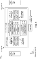
- FIG. 1 depicts an example of a system 100 that includes a mandrel 110 and a demolding tool 130.
- the mandrel 110 is shaped to define the shape of a workpiece (e.g., workpiece 120 of FIG. 1 ), and the demolding tool 130 is configured to facilitate removal of the workpiece 120 from the mandrel 110 after the workpiece 120 is at least partially cured on the mandrel 110.
- FIG. 1 also illustrates a plurality of orthogonal axes 190, including an X-axis, a Y-axis, and a Z-axis.
- first ends 136 and second ends 138 are labeled in FIG. 1 as first ends 136 and second ends 138.
- a "first end" of the workpiece 120 is a portion of the workpiece 120 that is disposed adjacent to a "first end" of the mandrel 110.
- first ends 136 and second ends 138 are arbitrary but is used consistently herein.
- the workpiece 120 include a plurality of layers of laminate material 122, such as a plurality of layers of polymer impregnated fiber tows (commonly referred to as "pre-preg" tows) or other fiber-reinforced polymer materials that are arranged on the mandrel 110 to define a skin 126 having a shape corresponding to a shape of the mandrel 110.
- the workpiece 120 also includes stringers 124 (e.g., elongated structural members) that extend in one or more directions, such as in the longitudinal direction 192, to stiffen or otherwise mechanically support the skin 126.
- the mandrel 110 includes stringer troughs 114 to define shapes of the stringers 124.
- the stringer troughs 114 are high aspect ratio (e.g., each having a length that is significantly greater than its width) channels defined in a surface of the mandrel 110 to shape (e.g., mold) and retain the stringers 124 during curing of the layers of laminate material 122.
- the workpiece 120 when cured, fully encircles at least a portion of the mandrel 110.
- the workpiece 120, or a portion of the workpiece 120 defines a tubular shape around a portion of the mandrel 110.
- the mandrel 110 and the workpiece 120 may each have a tapered shape with uneven cross-sectional areas spaced apart along the longitudinal direction 192.
- the cross-sectional area of the first end of the mandrel 110 may be smaller than the cross-sectional area of the second end of the mandrel 110.
- the workpiece 120 is not moveable relative to the mandrel 110 after the workpiece 120 cures because the encircling portion of the workpiece 120 inhibits vertical movement (e.g., along the Z-axis in FIG. 1 ) and lateral movement (e.g., along the Y-axis of FIG. 1 ), and interaction of the stringers 124 and the stringer troughs 114 inhibits longitudinal movement (e.g., along the X-axis or along longitudinal direction 192 of FIG. 1 ).
- the mandrel 110 enables formation of a fully encircling or tubular workpiece 120, it can be challenging to remove the workpiece 120 from the mandrel 110.
- the demolding tool 130 is configured to facilitate removal of the workpiece 120 from the mandrel 110 without disassembling the mandrel 110 by using a flay demolding process, which is described further below.
- the mandrel 110 can be a unitary or single-piece mandrel.
- the demolding tool 130 includes a frame structure 132 coupled to a first plurality of actuators 160 and a second plurality of actuators 170.
- Each actuator of the first plurality of actuators 160 (such as representative actuator 162) is coupled to at least one coupler of a first plurality of couplers 140 (such as to representative coupler 142).
- each actuator of the second plurality of actuators 170 (such as representative actuator 172) is coupled to at least one coupler of a second plurality of couplers 150 (such as to representative coupler 152).
- the first plurality of couplers 140 are arranged to couple to a first end of the workpiece 120 while the workpiece 120 is disposed on the mandrel 110.
- the second plurality of couplers 150 are arranged to couple to the workpiece 120 at locations between the first end of the workpiece 120 and the second end of the workpiece 120.
- each of the couplers 140, 150 is a surface coupler, such as a suction cup, a vacuum coupler, an adhesive coupler, or another coupler that attaches by contact with an external surface of the workpiece 120.
- each of the couplers 140, 150 is a subsurface coupler or a through coupler, such as a bolt, a pin, a threaded insert, or another coupler that extends past the external surface of the workpiece 120 into the workpiece 120.
- the couplers 140, 150 include a mix of surface couplers, and subsurface couplers/through couplers.
- the demolding tool 130 includes or is coupled to a controller 134.
- the controller 134 includes special purpose circuitry and/or one or more processors coupled to a memory.
- the memory includes a non-transitory computer-readable medium that stores instructions that are executable by the processor(s). For example, the instructions are executable to initiate, perform or control operations to aid in removal of the workpiece 120 from the mandrel 110.
- the processor(s) can be implemented as a single processor or as multiple processors, such as in a multi-core configuration, a multi-processor configuration, a distributed computing configuration, a cloud computing configuration, or any combination thereof.
- one or more portions of the controller 134 are implemented using dedicated hardware, firmware, or a combination thereof.
- the controller 134 is configured to control operation of the actuators 160, 170 (e.g., by sending control signals to the actuators 160, 170), and possibly other components, such as a cutter 180, sensors, etc., during the flay demolding process.
- the controller 134 is configured to send control signals to cause one or more of the actuators 160, 170 to pre-tension one or more of the couplers 140, 150 with respect to the workpiece 120 before the cutter 180 cuts the workpiece 120.
- the controller 134 is configured to send control signals to cause one or more of the actuators 160, 170 to apply forces to at least partially disengage the first end of the workpiece 120 from the first end of the mandrel 110, and after at least partially disengaging the first end of the workpiece 120 from the first end of the mandrel 110, to apply forces to at least partially disengage the second end of the workpiece 120 from the mandrel 110.
- Controlling the flay demolding process in this manner has various benefits. For example, pre-tensioning one or more of the couplers 140, 150 limits longitudinal movement of the workpiece 120 relative to the mandrel 110 during and after cutting the workpiece 120.
- Such longitudinal movement could result in high contact pressure between ends of the stringers 124 and ends of the stringer troughs 114, which could damage the workpiece 120, the mandrel 110, or both.
- modeling has shown that at least partially disengaging the first end of the workpiece 120 (e.g., a smaller end of the workpiece 120) from the first end of the mandrel 110 before applying forces to at least partially disengage the second end of the workpiece 120 (e.g., a larger end of the workpiece 120) from the mandrel 110 limits stresses induced within the workpiece 120 and contact pressure between ends of the stringers 124 and ends of the stringer troughs 114 to within acceptable tolerances while deforming the workpiece 120 sufficiently to remove the workpiece 120 from the mandrel 110.
- one or more of the couplers 140, 150 are positioned to couple to the workpiece 120 at locations that overlying ends of one or more of the stringers 124.
- each of the first plurality of couplers 140 is positioned to couple to the workpiece 120 at a location radially overlying a respective stringer of the plurality of stringers 124.
- applying forces to at least partially disengaging the first end of the workpiece 120 from the first end of the mandrel 110 before applying forces to at least partially disengage the second end of the workpiece 120 from the mandrel 110 disengages the first ends of the stringers 124 from corresponding stringer troughs 114 early in the flay demolding process so that subsequent longitudinal movement between the workpiece 120 and the mandrel 110 does not damage the first ends of the stringers 124 or the stringer troughs 114.
- the layers of laminate material 122 are applied to the mandrel 110 to form the skin 126.
- material is deposited or applied in the stringer troughs 114 before the layers of the laminate material 122 of the skin 126 are applied to the mandrel 110 so that the stringer 124 and the skin 126 cure together.
- layup of the layers of laminate material 122 is performed using one or more automated fiber placement tools.
- the automated fiber placement tool(s) may be too large to fit in the demolding tool 130, in which case layup is performed remote from or outside of the demolding tool 130.
- the layers of laminate material 122 are cured or partially cured (e.g., sufficiently cured for the workpiece 120 to be mechanically stable), and the workpiece 120 and mandrel 110 are positioned in the demolding tool 130.
- the mandrel 110 or the demolding tool 130 may be mounted on rollers, tracks, or another mechanism to enable relative motion of the mandrel 110 and the demolding tool 130.
- the couplers 140, 150 are attached to the workpiece 120.
- the couplers 140, 150 include sub-surface or through couplers, in which case the couplers 140, 150 or portions thereof (such as posts, bolts, washers, threaded inserts, are disposed in or through the workpiece 120 during the layup operation or after curing and before the couplers 140, 150 are attached to the workpiece 120.
- the couplers 140, 150 include surface couplers which can be attached to the workpiece 120 while the workpiece 120 is in position relative to the demolding tool 130.
- a vacuum cup of the coupler 142 can be coupled to the surface of the workpiece 120 after the workpiece 120 is in position relative to the demolding tool 130.
- the positions of at least some of the couplers 140, 150 on the surface of the workpiece 120 are carefully controlled.
- the coupler 142 can be coupled to the surface of the workpiece 120 at a location that radially overlies one of the stringers 124.
- the couplers 140, 150 are de-attached from the actuators 160, 170 during attachment to the workpiece 120. In such implementations, the couplers 140, 150 are attached to the actuators 160, 170 after the couplers 140, 150 are attached to the workpiece 120. In other implementations, the couplers 140, 150 remain attached to the actuators 160, 170 during attachment of the couplers 140, 150 to the workpiece 120.
- the controller 134 sends control signals to one or more of the actuators 160, 170 to pre-tension the one or more of the actuators 160, 170 and respective couplers 140, 150.
- pre-tensioning refers to using an actuator to applying sufficient force to a coupler to remove slack between the workpiece 120 and the frame structure 132, or put another way, to ensure that joints, couplings, and members between the frame structure 132 and the workpiece 120 are in tension.
- the controller 134 is configured to send control signals to a subset of the actuators 160, 170 (such as to the first plurality of actuators 160, to the second plurality of actuators 170, or to some of each plurality of actuators 160, 170) to cause the subset of the actuators 160, 170 to pre-tension respective ones of the couplers 140, 150 with respect to the workpiece 120. Pre-tensioning at least some of the couplers 140, 150 inhibits movement of ends of the stringers 124 towards ends of the stringer troughs 114 when a cut is made in the workpiece 120.
- the cutter 180 is activated to cut the workpiece 120 along the longitudinal direction 192.
- the cutter 180 cuts the workpiece 120 end-to-end at or near a bottom (e.g., a lowest vertical or Z-axis location in FIG. 1 ) of the workpiece 120.
- cut edges 128 of the workpiece 120 may be supported by the actuators 160, 170, or may be allowed to sag such that a portion of the workpiece 120 adjacent to the cut edges 128 at least partially disengages from the mandrel 110.
- the mandrel 110 has a tapered shape along the longitudinal direction (e.g., the first end of the mandrel 110 has a cross-sectional area that is smaller than a cross-sectional area of the second end of the mandrel 110).
- the stringer troughs 114 converge toward the first end of the mandrel 110. Cutting the workpiece 120 can free the workpiece 120 from the mandrel 110 sufficiently to allow the workpiece 120 to shift toward the first end of the mandrel 110, which can allow enough contact pressure between the ends of the stringers 124 and the stringer troughs 114 to damage or delaminate the stringers 124.
- Pre-tensioned at least a subset of the actuators 160, 170 before cutting the workpiece 120 inhibits such motion during and after the cutting operation and protects the stringers 124 from damage.
- the controller 134 sends control signals to cause the first plurality of actuators 160 to apply first forces to the workpiece 120 via the first plurality of couplers 140.
- the first forces are sufficient to deform the workpiece 120 and at least partially disengage the first end of the workpiece 120 from the first end of the mandrel 110.
- the first forces applied by the first plurality of actuators 160 have components along all three of the orthogonal axes 190 of FIG. 1 .
- the first plurality of actuators 160 pull the workpiece 120 upward (along the Z-axis) to keep the stringers 124 aligned vertically with the stringer troughs 114, pull the workpiece 120 longitudinal (e.g., toward the second ends 138 along the X-axis) to reduce contact pressure between first ends of the stringers 124 and first ends of the stringer troughs 114, and pull the workpiece 120 laterally (e.g., along the Y-axis) to peel (or otherwise deform) the first end of the workpiece 120 away from the first end of the mandrel 110.
- the controller 134 sends control signals to cause the second plurality of actuators 170 to apply second forces to the workpiece 120 via the second plurality of couplers 150.
- the second forces further deform the workpiece 120 and at least partially disengage the second end of the workpiece 120 from the mandrel 110.
- the second forces applied by the second plurality of actuators 170 have components along two of the orthogonal axes 190 of FIG. 1 .
- the second plurality of actuators 170 pull the workpiece 120 upward (along the Z-axis) and pull the workpiece 120 laterally (e.g., along the Y-axis) to peel (or otherwise deform) the second end of the workpiece 120 away from the second end of the mandrel 110.
- the actuators 160, 170 apply third forces to lift the workpiece 120 from the mandrel 110.
- the mandrel 110 is lowered to remove the mandrel 110 from the workpiece 120.
- the frame structure 132 is lifted to remove the workpiece 120 from the mandrel 110.
- longitudinal (e.g., along the X-axis) movement is used to fully remove the mandrel 110 from the interior of the workpiece 120.
- the same movement mechanism used to position the mandrel 110 and the workpiece 120 relative to the demolding tool 130 may be used to separate the mandrel 110 from the workpiece 120 and the demolding tool 130.
- the mandrel 110 is moveable on wheels, rollers, tracks, etc. to enable the mandrel 110 to be moved away from the workpiece 120 and the demolding tool 130.
- the demolding tool 130 is moveable on wheels, rollers, tracks, etc.
- one or more of the support(s) 112 of the mandrel 110 may be moved between the cut edges 128 of the workpiece 120 as the mandrel 110 and the workpiece 120 are separated.
- the mandrel 110 can support at both ends 136, 138 without interfering with removal of the workpiece 120 from the mandrel 110 after the workpiece 120 is cured.
- the workpiece 120 may be stabilized and retained by the demolding tool 130 during post-processing operations, such as inspection and splicing the cut edges 128 together.
- support rings 182, 184 are attached to one or both ends 136, 138 of the workpiece 120 to stabilize and retain the workpiece 120. In some such implementations, the support rings 182, 184 fully support the workpiece 120 to allow the workpiece 120 to be decoupled from and removed from the demolding tool 130.
- a flay demolding process using the demolding tool 130 enables removing the workpiece 120 from the mandrel 110 without breaking down or disassembling the mandrel 110 even though the workpiece 120 fully encircles a portion of the mandrel 110. Additionally, by using the flay demolding process with the demolding tool 130, the workpiece 120 can be finished with a single splice joint to join the cut edges 128.
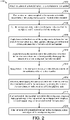
- FIG. 2 is flow chart of an example of a method 200 of using the demolding tool 130 of FIG. 1 to remove the workpiece 120 from the mandrel 110.
- the method 200 begins after a workpiece is cured or at least partially cured on a mandrel.
- layers of laminate material 122 of FIG. 1 can be applied to the mandrel 110 and cured or partially cured to conform to a shape defined by the mandrel 110.
- the workpiece 120 fully encircles at least a portion of the mandrel 110.
- the mandrel 110 is tapered.
- a first end of the mandrel 110 may have a smaller cross-sectional area than a second end of the mandrel 110.
- the mandrel 110 also includes stringer troughs 114 to facilitate curing stringers 124 to a skin 126 of the workpiece 120.
- the method 200 includes, at block 202, attaching couplers of a demolding tool to the workpiece on the mandrel.
- the couplers 140, 150 of FIG. 1 are coupled to the workpiece 120.
- the couplers 140, 150 include surface couplers, sub-surface couplers, through couplers, or a combination thereof.
- a first set of couplers 140, 150 e.g., the first plurality of couplers 140
- a second set of the couplers 140, 150 e.g., the second plurality of couplers 150
- the method 200 also includes, at block 204, pre-tensioning actuators coupled to the workpiece to inhibit movement of the workpiece toward a first end of the mandrel.
- pre-tensioning actuators coupled to the workpiece to inhibit movement of the workpiece toward a first end of the mandrel.
- at least a subset of the couplers 140, 150 are pre-tensioned by respective actuators 160, 170 to removes slack from between the workpiece 120 and the frame structure 132.
- the method 200 also includes, at block 206, after at least some of the couplers are pre-tensioned, cutting the workpiece along a direction between a first end of the workpiece and a second end of the workpiece. For example, while at least a subset of the couplers 140, 150 of FIG. 1 are in tension, the cutter 180 is activated to cut the bottom of the workpiece 120 end-to-end along the longitudinal direction 192. In some implementations, cutting the workpiece 120 allows at least a portion of the workpiece 120 to separate from the mandrel 110 due to sag at the cut edges 128 of the workpiece 120.
- the method 200 also includes, at block 208, applying forces (e.g., first forces after pre-tensioning) to the first end of the workpiece to deform the first end of the workpiece to at least partially disengage the first end of the workpiece from the first end of the mandrel.
- the first plurality of actuators 160 may be activated to apply the forces to the first end of the workpiece 120 via the first plurality of couplers 140.
- the forces applied to the workpiece 120 by the first plurality of actuators 160 via the first plurality of couplers 140 have components along a lateral axis (e.g., the Y-axis in FIG. 1 ), a vertical axis (e.g., the Z-axis in FIG. 1 ), and the longitudinal axis (e.g., the X-axis in FIG. 1 ).
- the method 200 also includes, at block 210, applying forces (e.g., second forces after pre-tensioning) to the second end of the workpiece to further deform the workpiece and at least partially disengage the second end of the workpiece from the mandrel.
- the second plurality of actuators 170 may be activated to apply the forces to the second end of the workpiece 120 via the second plurality of couplers 150.
- the forces applied to the workpiece 120 by the second plurality of actuators 170 via the second plurality of couplers 150 have components along the lateral axis (e.g., the Y-axis in FIG. 1 ) and the vertical axis (e.g., the Z-axis in FIG. 1 ).
- forces applied by the second plurality of actuators 170 also have components along the longitudinal axis (e.g., the X-axis in FIG. 1 ); however, in other implementations, the forces applied by the second plurality of actuators 170 do not have components along the longitudinal axis.
- the method 200 also includes, at block 212, applying forces (e.g., third forces after pre-tensioning) to the workpiece to cause vertical displacement of the workpiece relative to the mandrel.
- forces e.g., third forces after pre-tensioning
- one or more actuators of the second plurality of actuators 170 may be coupled to an upper surface of the workpiece 120 and may lift the workpiece 120 away from the mandrel 110.
- the mandrel 110 can be lowered to cause vertical displacement of the workpiece 120 relative to the mandrel 110.
- lowering the mandrel 110 can be used in addition to applying lifting forces to the workpiece 120, or lowering the mandrel 110 can be used instead of applying lifting forces to the workpiece 120.
- the method 200 also includes, at block 214, after fully disengaging the workpiece from the mandrel, removing the mandrel from within the workpiece by moving the mandrel, the workpiece, or both, relative to the longitudinal direction.
- the mandrel 110 can be moved along the longitudinal direction 192 to remove the mandrel 110 from within the workpiece 120.
- one or more supports 112 of the mandrel 110 move between the cut edges 128 of the workpiece 120 as the mandrel 110 is removed from within the workpiece 120.
- the method 200 also includes, at block 216, after removal of the mandrel from within the workpiece, coupling a first support ring to the first end of the workpiece and coupling a second support ring to the second end of the workpiece.
- a first support ring 182 of FIG. 1 is coupled to the first end of the workpiece 120
- the second support ring 184 is coupled to the second end of the workpiece 120.
- the method 200 also includes, at block 218, after removal of the mandrel from within the workpiece, splicing cut edges of the workpiece together.
- the cut edges 128 of the workpiece 120 can be joined together using a splice joint, as described further with reference to FIGS. 16A and 16B .
- the method 200 enables separation of the mandrel 110 and the workpiece 120 without disassembling the mandrel 110 and using a single splice joint to join the cut edges 128.
- FIGS. 3A-16B illustrate various examples of the components described with reference to FIG. 1 in the context of aircraft manufacturing.
- the workpiece 120 corresponds to a section of a structure of an aircraft, such as a portion of a fuselage of an aircraft.
- other aircraft components or workpieces unrelated to aircraft can be manufactured using the system 100 of FIG. 1 .
- FIGS. 3A and 3B illustrate a perspective view and a side view, respectively, of an example of the mandrel 110 of FIG. 1 according to a particular implementation.
- a surface 302 of the mandrel 110 is shaped to form a portion of a fuselage of an aircraft, such as a forward section of the fuselage.
- the mandrel 110 has a tapered shape such that the first end 136 of the mandrel 110 has a smaller cross-sectional area than the second end 138 of the mandrel 110.
- FIGS. 3A and 3B also illustrate examples of the stringer troughs 114 of FIG. 1 .
- the stringer troughs 114 extend longitudinally (e.g., along the X-axis) on the surface 302 of the mandrel 110.
- the stringer troughs 114 converge toward the first end 136 of the mandrel 110.
- FIGS. 3A and 3B also illustrate an example of the support(s) 112 of FIG. 1 .
- FIGS. 3A and 3B illustrate only a single support 112 at the first end 136 of the mandrel 110; however, in other examples, the mandrel 110 includes one or more additional supports 112 at the first end 136, one or more supports 112 at the second end 138, or both.
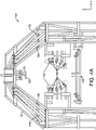
- FIGS. 4A and 4B illustrate an end view and a perspective view, respectively, of an example of the demolding tool 130 of FIG. 1 according to a particular implementation.
- the demolding tool 130 in FIGS. 4A and 4B includes the frame structure 132, the first plurality of actuators 160, and the second plurality of actuators 170.
- the first plurality of couplers 140 are attached to the first plurality of actuators 160
- the second plurality of couplers 150 are attached to the second plurality of actuators 170.
- FIG. 4A also illustrates a gap 402 of the frame structure 132.
- the gap 402 enables one or more of the supports 112 of the mandrel 110 to pass between members of the frame structure 132 as the mandrel 110 is moved relative to the demolding tool 130.
- FIG. 4B illustrates a coupler 450 attached to an actuator 470.
- the coupler 450 and the actuator 470 are located forward of the second plurality of couplers 150 and the second plurality of actuators 170 (e.g., closer to the first end 136 than the second end).
- the coupler 450 and the actuator 470 are considered members of the second plurality of couplers 150 and the second plurality of actuators 170, respectively.
- the actuator 470 can be controlled by the controller 134 of FIG. 1 when the controller 134 controls the second plurality of actuators 170.
- the coupler 450 and the actuator 470 are distinct from (e.g., not members of) the second plurality of couplers 150 and the second plurality of actuators 170, respectively.
- the controller 134 may control the actuators 470 independently of the first and second pluralities of actuators 160, 170.
- the actuator 470 can be used to lift the workpiece 120 from the mandrel 110 after the first and second pluralities of actuators 160, 170 have been actuated to disengage the ends 136, 138 of the workpiece 120 from the mandrel 110.
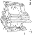
- FIG. 5 illustrates a perspective view of an example of the demolding tool 130 and the workpiece 120 of FIG. 1 according to a particular implementation.
- the example illustrated in FIG. 5 illustrates the couplers 140, 150 coupled to the workpiece 120, which is supported in the frame structure 132.
- FIG. 6 illustrates a perspective view of an example of the workpiece 120 and couplers 140, 150, 450 and actuators 160, 170, 470 of the demolding tool 130 according to a particular implementation.
- FIG. 6 also illustrates examples of the stringers 124 extending longitudinally from the first end 136 toward the second end 138 of the workpiece 120.
- FIG. 6 illustrates a coupler 650 attached to an actuator 670.
- the coupler 650 and the actuator 670 are located forward of the second plurality of couplers 150 and the second plurality of actuators 170 (e.g., closer to the first end 136 than the second end 138).
- the coupler 650 and the actuator 670 are consider members of the first plurality of couplers 140 and the first plurality of actuators 160, respectively.
- the actuator 670 can be controlled by the controller 134 of FIG. 1 when the controller 134 controls the first plurality of actuators 160.
- the coupler 650 and the actuator 670 are consider members of the second plurality of couplers 150 and the second plurality of actuators 170, respectively.
- the coupler 650 and the actuator 670 are distinct from (e.g., not members of) the first or second plurality of couplers 140, 150 and the first or second plurality of actuators 160, 170, respectively.
- the controller 134 may control the actuators 670 independently of the first and second pluralities of actuators 160, 170.
- FIG. 7 illustrates a perspective view of an example of the workpiece 120 and components of force applied to the workpiece 120 by the actuators 160, 170 of the demolding tool 130 of FIG. 1 during a demolding process according to a particular implementation.
- the illustrated components of force include first components of force 702 applied by the first plurality of actuators 160, second components of force 704 applied by the second plurality of actuators 170, third components of force 706 applied by the actuator 670 of FIG. 6 , and fourth components of force 708 applied by the actuator 470 of FIG. 4B .
- the first components of force 702 are along all three of the orthogonal axes 190 (e.g., the X-axis, the Y-axis, and the Z-axis), whereas the second components of force 702, the third components of force 704, and the fourth components of force 708 are along two of the three orthogonal axes 190 (e.g., the Y-axis and the Z-axis).
- FIGS. 8A-11B illustrate deformation of the workpiece 120 during various stages of a demolding process according to a particular implementation.
- Each of FIGS. 8A , 9A , 10A and 11A illustrates an end view of an example of the workpiece 120 disposed in the demolding tool 130 during a respective stage of the demolding process.
- Each of FIGS. 8B , 9B , 10B and 11B illustrates a top view of an example of the workpiece 120 disposed in the demolding tool 130 during a respective stage of the demolding process.
- FIGS. 8A and 8B illustrate a first stage of the demolding process
- FIGS. 9A and 9B illustrate a second stage of a demolding process that is subsequent to the first stage.
- FIGS. 10A and 10B illustrate a third stage of a demolding process that is subsequent to the second stage.
- FIGS. 11A and 11B illustrate a fourth stage of a demolding process that is subsequent to the third stage.
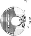
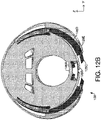
- FIGS. 12A , 12B and 12C illustrate a first end view, a second end view, and a cutaway perspective second end view, respectively, of an example of the workpiece 120 as deformed during various stages of the demolding process of FIGS. 8A-11B .
- the skin 126 is shown in five configurations.
- a first configuration of the skin 126A illustrates a shape of the workpiece 120 while the workpiece 120 is on the mandrel 110 and before the workpiece 120 is cut.
- a second configuration of the skin 126B illustrates a shape of the workpiece 120 while the workpiece 120 is on the mandrel 110 and after the workpiece 120 is cut and the cut edges 128 are allowed to sag apart.
- the first configuration of the skin 126A and the second configuration of the skin 126B are also illustrated in FIGS. 8A and 8B .
- FIGS. 12A-12C also illustrate a third configuration of the skin 126C which illustrates a shape of the workpiece 120 after the first plurality of actuators 160 apply first forces to the first end 136 of the workpiece 120 to at least partially disengage the first end 136 of the workpiece 120 from the first end 136 of the mandrel 110.
- the second configuration of the skin 126B and the third configuration of the skin 126C are also illustrated in FIGS. 9A and 9B .
- FIGS. 12A-12C also illustrate a fourth configuration of the skin 126D which illustrates a shape of the workpiece 120 after the second plurality of actuators 170 apply second forces to the second end 138 of the workpiece 120 (or between the first plurality of couplers 140 and the second end 138) to at least partially disengage the second end 138 of the workpiece 120 from the second end 138 of the mandrel 110.
- the third configuration of the skin 126C and the fourth configuration of the skin 126D are also illustrated in FIGS. 10A and 10B .
- FIGS. 12A-12C also illustrate a fifth configuration of the skin 126E which illustrates a shape of the workpiece 120 after the workpiece 120 is fully disengaged from the mandrel 110 and retained by the demolding tool 130.
- the fourth configuration of the skin 126D and the fifth configuration of the skin 126E are also illustrated in FIGS. 11A and 11B .
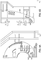
- FIGS. 8A-12C The order of the stages of the demolding process of FIGS. 8A-12C have been shown by modeling to result in deformations of the workpiece 120 that are within manufacturing and structural limitations of the workpiece 120.
- the order in which the forces are applied in the example of FIGS. 8A-12C inhibits movement of the workpiece 120 toward the first end 136, which could subject ends of the stringers 124 to excessive contact pressure with the stringer troughs 114.
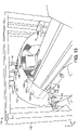
- FIG. 13 illustrate a perspective view of an example of a post-processing fixture 1302 disposed within the workpiece 120 after the mandrel 110 has been removed and while the workpiece 120 is retained by the demolding tool 130 according to a particular implementation.
- the post-processing fixture 1302 includes or is coupled to one or more post-processing tools 1304.
- the post-processing tool(s) 1304 may include non-destructive inspection tools that facilitate inspection of an interior surface of the workpiece 120, through inspection of the workpiece walls, or both.
- the non-destructive inspection tools can include laser measurement tools to measure interior dimensions of the workpiece 120 or cameras to check for surface defects.
- non-destructive inspection tools on the post-processing fixtures 1302 interact with non-destructive inspection tools external to the workpiece 120 to gather data.
- ultrasound emitters or an x-ray source may be mounted to the post-processing fixture 1302 to generate signals that are detected by detectors outside the workpiece 120 for gathering non-destructive inspection data about the skin 126, the stringers 124, or both.
- the post-processing tool(s) 1304 may include surface finishing equipment, such as painters, drills, cutters, or polishers.
- the post-processing tool(s) 1304 can include any tool that facilitates preparation of the workpiece 120 for subsequent manufacturing steps.
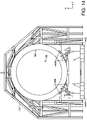
- FIG. 14 illustrate an end view of an example of a ring fixture 1402 coupled to the workpiece of FIG. 1 after the mandrel 110 has been removed and while the workpiece 120 is disposed with the demolding tool 130 according to a particular implementation.
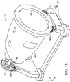
- FIG. 15 illustrate a perspective view of an example of the ring fixture 1402 coupled to the workpiece 120 after the workpiece 120 has been removed from the demolding tool 130 according to a particular implementation.
- the ring fixture 1402 includes a plurality of support rings, including the first support ring 182 and the second support ring 184.
- the ring fixture 1402 also includes a first set of rollers 1408 to enable movement of the ring fixture 1402 relative to the frame structure 132 of the demolding tool 130.
- the ring fixture 1402 includes a second set of rollers 1406 and a third set of rollers 1502 (shown in FIG. 15 ) to enable rotation of the workpiece 120 while the workpiece 120 is supported by the ring fixture 1402.
- the third set of rollers 1502 directly supports a third support ring 1504, which is coupled via an axle 1508 to the first support ring 182.
- the support rings 182, 184 retain the shape of the workpiece 120.
- the support rings 182, 184 attach to the workpiece 120 such that the cut edges 128 of the workpiece 120 are positioned to be spliced together (e.g., touching or nearly touching each other).
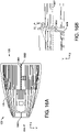
- FIGS. 16A illustrate a bottom exterior view of the workpiece 120 and indicates a cut line 1602 used for the demolding process according to a particular implementation. Cutting along the cut line 1602 separates the skin 126 at the cut edges 128A and 128B. After the demolding process, the cut edges 128 are reattached to one another using a splice joint.
- FIGS. 16B illustrate an interior view of the workpiece 120 at the cut line 1602.
- FIG. 16B shows details of a splice used to join the cut edges 128 together according to a particular implementation.
- a splice fitting 1604 is coupled to a rib 1606 on an interior surface of the workpiece 120 to join the cut edges 128 together.
- the rib 1606 is formed in the same manner as the stringers 124.
- the rib 1606 may include laminate material that is disposed in a rib forming feature (e.g., a channel) in the surface of the mandrel 110 during layup and is subsequently cured with the layers of laminate material 122 of the skin 126 to form the workpiece 120.
- a rib forming feature e.g., a channel
- the rib 1606 is attached to the interior surface of the workpiece 120 during post-processing of the workpiece 120. After the splice joint is complete, the workpiece 120 is ready for subsequent processing, such as assembly with one or more other components to manufacture a fuselage or other structure of an aircraft.
- a demolding tool comprises a first plurality of couplers arranged to couple to a first end of a workpiece disposed on a mandrel, the mandrel having a first end disposed adjacent to the first end of the workpiece and having a second end disposed adjacent to a second end of the workpiece, wherein the first end of the mandrel has a first cross-sectional area that is smaller than a second cross-sectional area of the second end of the mandrel; a first plurality of actuators, each actuator of the first plurality of actuators coupled to at least one of the first plurality of couplers; a second plurality of couplers arranged to couple to the workpiece at locations between the first end of the workpiece and the second end of the workpiece; a second plurality of actuators, each actuator of the second plurality of actuators coupled to at least one of the second plurality of couplers; and a controller configured to, after a cut is formed in the workpiece along a longitudinal direction between
- Clause 2 includes the demolding tool of Clause 1, wherein the workpiece comprises layers of laminate material cured on the mandrel to define a skin having a shape corresponding to a shape of the mandrel.
- Clause 3 includes the demolding tool of Clause 1 or Clause 2, wherein the mandrel defines a plurality of stringer troughs and the workpiece further comprises a plurality of stringers coupled to the skin and cured within the plurality of stringer troughs.
- Clause 4 includes the demolding tool of Clause 3, wherein the plurality of stringer troughs converge toward the first end of the mandrel.
- Clause 5 includes the demolding tool of Clause 3 or Clause 4, wherein the controller is further configured to, before causing the first plurality of actuators to apply the first forces, cause the first plurality of actuators to pre-tension the first plurality of couplers with respect to the workpiece to inhibit movement of ends of the stringers towards ends of the stringer troughs.
- Clause 6 includes the demolding tool of any of Clauses 3 to 5, wherein each of the first plurality of couplers is positioned to couple to the workpiece at a location radially overlying a respective stringer of the plurality of stringers.
- Clause 7 includes the demolding tool of any of Clauses 1 to 6, wherein one or more of the first plurality of couplers includes a suction cup or vacuum coupler.
- Clause 8 includes the demolding tool of any of Clauses 1 to 7, wherein the first plurality of actuators and the first plurality of couplers are configured to apply forces having components along at least three orthogonal axes to the workpiece, and wherein the second plurality of actuators and the second plurality of couplers are configured to apply forces having components along at least two of the three orthogonal axes of the workpiece.
- Clause 9 includes the demolding tool of any of Clauses 1 to 8, wherein the workpiece corresponds to a section of a structure of an aircraft.
- Clause 10 includes the demolding tool of any of Clauses 1 to 9, further comprising a frame structure coupled to the first plurality of actuators and the second plurality of actuators.
- Clause 11 describes a method of removing from a mandrel a workpiece having a tubular shape defining a plurality of unequal circumferences spaced apart along a longitudinal axis, the method comprising: after the workpiece is cured on the mandrel, cutting the workpiece along a direction between a first end of the workpiece and a second end of the workpiece, wherein the first end of the workpiece has a first circumference that is smaller than a second circumference of the second end of the workpiece; applying first forces to the first end of the workpiece to deform the first end of the workpiece to at least partially disengage the first end of the workpiece from the first end of the mandrel; and after applying the first forces, applying second forces to the second end of the workpiece to further deform the workpiece and at least partially disengage the second end of the workpiece from the mandrel.
- Clause 12 includes the method of Clause 11, wherein the first forces are applied after at least a portion of the workpiece separates from the mandrel due to sag at cut edges of the workpiece.
- Clause 13 includes the method of either Clause 11 or Clause 12, further comprising, before applying the first forces, pre-tensioning actuators coupled to the workpiece to inhibit movement of the workpiece toward the first end of the mandrel.
- Clause 14 includes the method of any of Clauses 11 to 13, further comprising, after applying the second forces, applying third forces to the workpiece to cause vertical displacement of the workpiece relative to the mandrel.
- Clause 15 includes the method of any of Clauses 11 to 14, further comprising, after fully disengaging the workpiece from the mandrel, removing the mandrel from within the workpiece by moving the mandrel, the workpiece, or both, relative to the longitudinal axis.
- Clause 16 includes the method of Clause 15, wherein the mandrel comprises a support coupled to the first end of the mandrel and wherein the support moves between cut edges of the workpiece during removal of the mandrel from within the workpiece.
- Clause 17 includes the method of either Clause 15 or Clause 16, further comprising, after removing the mandrel from within the workpiece, coupling a first support ring to the first end of the workpiece and coupling a second support ring to the second end of the workpiece.
- Clause 18 includes the method of any of Clauses 15 to 17, further comprising, after removing the mandrel from within the workpiece, splicing cut edges of the workpiece together.
- Clause 19 includes the method of any of Clauses 11 to 18, wherein the first forces have components along a lateral axis, a vertical axis, and the longitudinal axis, and wherein the second forces have components along the lateral axis and the vertical axis.
- a system comprises: a mandrel contoured to define a tapering tubular shape of a workpiece cured on the mandrel; and a demolding tool configured to remove the workpiece from the mandrel after the workpiece is cured on the mandrel and cut longitudinally, wherein the demolding tool is configured to remove the workpiece from the mandrel by deforming a first end of the workpiece to at least partially disengage the first end of the workpiece from a first end of the mandrel, and subsequently, deforming a second end of the workpiece to at least partially disengage the second end of the workpiece from a second end of the mandrel, wherein the first end of the workpiece has a first cross-sectional area that is smaller than a second cross-sectional area of the second end of the workpiece.
- Clause 21 includes the system of Clause 20, wherein the demolding tool comprises: a first plurality of couplers arranged to couple to a first end of the workpiece; a first plurality of actuators, each actuator of the first plurality of actuators coupled to at least one of the first plurality of couplers; a second plurality of couplers arranged to couple to the workpiece at locations between the first end of the workpiece and the second end of the workpiece; and a second plurality of actuators, each actuator of the second plurality of actuators coupled to at least one of the second plurality of couplers.
- Clause 22 describes a method of removing a workpiece from a mandrel, the method comprising: applying forces to the workpiece while cutting the workpiece along a longitudinal direction between a first end of the workpiece and a second end of the workpiece; after cutting the workpiece, applying forces to disengage a first end of the workpiece from the mandrel; and disengaging the first end of the workpiece from the mandrel, applying forces to the second end of the workpiece to deform the workpiece and disengage the second end of the workpiece from the mandrel.
- Clause 23 includes the method of Clause 22, further comprising, after disengaging the second end of the workpiece from the mandrel, applying forces to the workpiece to cause vertical displacement of the workpiece relative to the mandrel.
- Clause 24 includes the method of either Clause 22 or Clause 23, further comprising, after fully disengaging the workpiece from the mandrel, removing the mandrel from within the workpiece by moving the mandrel, the workpiece, or both, relative to the longitudinal direction.
- a non-transitory, computer readable medium stores instructions that, when executed by one or more processors, cause the one or more processors to initiate, perform, or control operations to perform part or all of the functionality described above.
- the instructions may be executable to implement one or more of the operations or methods of FIG. 2 .
- part or all of one or more of the operations or methods of FIG. 2 may be initiated, performed, or controlled by one or more processors (e.g., one or more central processing units (CPUs), one or more graphics processing units (GPUs), one or more digital signal processors (DSPs)) executing instructions, by dedicated hardware circuitry, or any combination thereof.
- processors e.g., one or more central processing units (CPUs), one or more graphics processing units (GPUs), one or more digital signal processors (DSPs)
Landscapes
- Engineering & Computer Science (AREA)
- Mechanical Engineering (AREA)
- Aviation & Aerospace Engineering (AREA)
- Chemical & Material Sciences (AREA)
- Composite Materials (AREA)
- Manufacturing & Machinery (AREA)
- Architecture (AREA)
- Civil Engineering (AREA)
- Structural Engineering (AREA)
- Transportation (AREA)
- Moulding By Coating Moulds (AREA)
Abstract
Description
- The present disclosure is generally related to demolding tools and methods.
- Mandrels are often used to shape composite materials during manufacturing. For example, a mandrel may be used to define the shape of the composite materials during layup and curing. In some circumstances, it can be challenging to remove the composite materials from the mandrel after curing. To illustrate, when cured composite parts have certain shapes, there may be no simple way to pull the composite parts off of the mandrel without risking damage to the part, the mandrel, or both. For example, when a composite part fully encircles at least a portion of the mandrel, it can be challenging to remove the composite part from the mandrel.
- Sometimes a breakdown mandrel is used to facilitate removal of a composite part from a mandrel without damaging the part or the mandrel. A breakdown mandrel includes several pieces that are assembled together to define the shape of the mandrel before composite materials are applied to the mandrel. After curing the composite materials, the mandrel is at least partially disassembled (e.g., one or more of the pieces of the mandrel are removed) to separate the cured composite part from the mandrel.
- A breakdown mandrel is significantly more difficult to design and manufacture than a unitary or single-piece mandrel of the same size and shape and is therefore also significantly more expensive. Additionally, using a breakdown mandrel can increase fabrication times because the breakdown mandrel has to be disassembled, cleaned, and reassembled for each use whereas a unitary mandrel is ready for reuse after cleaning. Ill-fitting pieces, improper cleaning, or mis-assembly of the breakdown mandrel can also lead to defects in the composite part, which may require the composite part to be scrapped or reworked.
- Another approach that may be used to remove a composite part from a mandrel is to cut the composite part into two or more pieces, and then reassemble the pieces. The pieces are subsequently joined together using two or more splice joints. Making each splice joint is time consuming, leading to higher manufacturing costs. Additionally, each splice joint adds additional weight to the composite part, which may be problematic when the final weight of the composite part is an important consideration, such as when the composite part is an aircraft component.
- In a particular implementation, a demolding tool includes a first plurality of couplers arranged to couple to a first end of a workpiece disposed on a mandrel. The mandrel includes a first end disposed adjacent to the first end of the workpiece and a second end disposed adjacent to a second end of the workpiece. The first end of the mandrel has a first cross-sectional area that is smaller than a second cross-sectional area of the second end of the mandrel. The demolding tool also includes a first plurality of actuators. Each actuator of the first plurality of actuators is coupled to at least one of the first plurality of couplers. The demolding tool further includes a second plurality of couplers arranged to couple to the workpiece at locations between the first end of the workpiece and the second end of the workpiece. The demolding tool also includes a second plurality of actuators. Each actuator of the second plurality of actuators is coupled to at least one of the second plurality of couplers. The demolding tool further includes a controller configured to, after a cut is formed in the workpiece along a longitudinal direction between the first end and the second end of the workpiece, cause the first plurality of actuators to apply, via the first plurality of couplers, first forces to the workpiece to deform the workpiece and at least partially disengage the first end of the workpiece from the first end of the mandrel. The controller is also configured to, after causing the first plurality of actuators to apply the first forces to the workpiece, cause the second plurality of actuators to apply, via the second plurality of couplers, second forces to the workpiece to further deform the workpiece and at least partially disengage the second end of the workpiece from the mandrel.
- In another particular implementation, a method of removing from a mandrel a workpiece having a tubular shape defining a plurality of unequal circumferences spaced apart along a longitudinal axis is disclosed. The method includes, after the workpiece is cured on the mandrel, cutting the workpiece along a direction between a first end of the workpiece and a second end of the workpiece. The first end of the workpiece has a first circumference that is smaller than a second circumference of the second end of the workpiece. The method also includes applying first forces to the first end of the workpiece to deform the first end of the workpiece to at least partially disengage the first end of the workpiece from the first end of the mandrel. The method further includes, after applying the first forces, applying second forces to the second end of the workpiece to further deform the workpiece and at least partially disengage the second end of the workpiece from the mandrel.
- In another particular implementation, a system includes a mandrel and a demolding tool. The mandrel is contoured to define a tapering tubular shape of a workpiece cured on the mandrel. The demolding tool is configured to remove the workpiece from the mandrel after the workpiece is cured on the mandrel and cut longitudinally. The demolding tool is configured to remove the workpiece from the mandrel by deforming a first end of the workpiece to at least partially disengage the first end of the workpiece from a first end of the mandrel, and subsequently, deforming a second end of the workpiece to at least partially disengage the second end of the workpiece from a second end of the mandrel. The first end of the workpiece has a first cross-sectional area that is smaller than a second cross-sectional area of the second end of the workpiece.
- In yet another particular implementation, a method of removing a workpiece from a mandrel includes applying forces to the workpiece while cutting the workpiece along a longitudinal direction between a first end of the workpiece and a second end of the workpiece. The method also includes, after cutting the workpiece, applying forces to disengage a first end of the workpiece from the mandrel. The method further includes, after disengaging the first end of the workpiece from the mandrel, applying forces to the second end of the workpiece to deform the workpiece and disengage the second end of the workpiece from the mandrel.
- The features, functions, and advantages described herein can be achieved independently in various implementations or may be combined in yet other implementations, further details of which can be found with reference to the following description and drawings.
-
-
FIG. 1 is a block diagram that illustrates a system including a demolding tool to facilitate removal of a workpiece from a mandrel. -
FIG. 2 is flow chart of an example of a method of using the demolding tool ofFIG. 1 to remove the workpiece from the mandrel. -
FIGS. 3A and 3B illustrate a perspective view and a side view, respectively, of an example of the mandrel ofFIG. 1 according to a particular implementation. -
FIGS. 4A and4B illustrate an end view and a perspective view, respectively, of an example of the demolding tool ofFIG. 1 according to a particular implementation. -
FIG. 5 illustrate a perspective view of an example of the demolding tool and the workpiece ofFIG. 1 according to a particular implementation. -
FIG. 6 illustrate a perspective view of an example of the workpiece and couplers and actuators of the demolding tool ofFIG. 1 according to a particular implementation. -
FIG. 7 illustrate a perspective view of an example of the workpiece and components of force applied to the workpiece by actuators of the demolding tool ofFIG. 1 during a demolding process according to a particular implementation. -
FIGS. 8A and 8B illustrate an end view and a top view, respectively, of an example of the workpiece disposed in the demolding tool ofFIG. 1 during a first stage of a demolding process according to a particular implementation. -
FIGS. 9A and 9B illustrate an end view and a top view, respectively, of an example of the workpiece disposed in the demolding tool ofFIG. 1 during a second stage of a demolding process according to a particular implementation. -
FIGS. 10A and 10B illustrate an end view and a top view, respectively, of an example of the workpiece disposed in the demolding tool ofFIG. 1 during a third stage of a demolding process according to a particular implementation. -
FIGS. 11A and 11B illustrate an end view and a top view, respectively, of an example of the workpiece disposed in the demolding tool ofFIG. 1 during a fourth stage of a demolding process according to a particular implementation. -
FIGS. 12A ,12B and12C illustrate a first end view, a second end view, and a cutaway perspective second end view, respectively, of an example of the workpiece ofFIG. 1 as deformed during various stages of a demolding process according to a particular implementation. -
FIG. 13 illustrate a perspective view of an example of a post-processing fixture disposed within the workpiece ofFIG. 1 after the mandrel has been removed and while the demolding tool is retaining the workpiece according to a particular implementation. -
FIG. 14 illustrate an end view of an example of a ring fixture coupled to the workpiece ofFIG. 1 after the mandrel has been removed and while the demolding tool is retaining the workpiece according to a particular implementation. -
FIG. 15 illustrate a perspective view of an example of a ring fixture coupled to the workpiece ofFIG. 1 after the workpiece has been removed from the demolding tool according to a particular implementation. -
FIGS. 16A illustrate a bottom exterior view of the workpiece ofFIG. 1 and indicates a cut line used for the demolding process according to a particular implementation. -
FIGS. 16B illustrate an interior view of the cut line ofFIG. 16 and shows details of a splice used to secure cut edges of the workpiece together according to a particular implementation. - Aspects disclosed herein present systems and methods for demolding a composite part (e.g., a workpiece) that fully encircles at least a portion of a mandrel. The disclosed systems and methods enable use of a unitary mandrel (rather than a breakdown mandrel) and a single splice joint.
- Particular implementations are described herein with reference to the drawings. In the description, common features are designated by common reference numbers throughout the drawings. The figures and the following description illustrate specific examples. It will be appreciated that those skilled in the art will be able to devise various arrangements that, although not explicitly described or shown herein, embody the principles described herein and are included within the scope of the claims that follow this description. Furthermore, any examples described herein are intended to aid in understanding the principles of the disclosure and are to be construed as being without limitation. As a result, this disclosure is not limited to the specific examples described below, but by the claims and their equivalents.
- As used herein, various terminology is used for the purpose of describing particular implementations only and is not intended to be limiting. For example, the singular forms "a," "an," and "the" are intended to include the plural forms as well, unless the context clearly indicates otherwise. Further, some features described herein are singular in some implementations and plural in other implementations. To illustrate,
FIG. 1 depicts asystem 100 including amandrel 110 including one or more supports ("support(s)" 112 inFIG. 1 ), which indicates that in some implementations themandrel 110 includes asingle support 112 and in other implementations themandrel 110 includesmultiple supports 112. For ease of reference herein, such features are generally introduced as "one or more" features and are subsequently referred to in the singular unless aspects related to multiple of the features are being described. - The terms "comprise," "comprises," and "comprising" are used interchangeably with "include," "includes," or "including." Additionally, the term "wherein" is used interchangeably with the term "where." As used herein, "exemplary" indicates an example, an implementation, and/or an aspect, and should not be construed as limiting or as indicating a preference or a preferred implementation. As used herein, an ordinal term (e.g., "first," "second," "third," etc.) used to modify an element, such as a structure, a component, an operation, etc., does not by itself indicate any priority or order of the element with respect to another element, but rather merely distinguishes the element from another element having a same name (but for use of the ordinal term). As used herein, the term "set" refers to a grouping of one or more elements, and the term "plurality" refers to multiple elements.
- As used herein, "generating", "calculating", "using", "selecting", "accessing", and "determining" are interchangeable unless context indicates otherwise. For example, "generating", "calculating", or "determining" a parameter (or a signal) can refer to actively generating, calculating, or determining the parameter (or the signal) or can refer to using, selecting, or accessing the parameter (or signal) that is already generated, such as by another component or device. As used herein, "coupled" can include "communicatively coupled," "electrically coupled," or "physically coupled," and can also (or alternatively) include any combinations thereof. Two devices (or components) can be coupled (e.g., communicatively coupled, electrically coupled, or physically coupled) directly or indirectly via one or more other devices, components, wires, buses, networks (e.g., a wired network, a wireless network, or a combination thereof), etc. Two devices (or components) that are electrically coupled can be included in the same device or in different devices and can be connected via electronics, one or more connectors, or inductive coupling, as illustrative, non-limiting examples. In some implementations, two devices (or components) that are communicatively coupled, such as in electrical communication, can send and receive electrical signals (digital signals or analog signals) directly or indirectly, such as via one or more wires, buses, networks, etc. As used herein, "directly coupled" is used to describe two devices that are coupled (e.g., communicatively coupled, electrically coupled, or physically coupled) without intervening components.
-
FIG. 1 depicts an example of asystem 100 that includes amandrel 110 and ademolding tool 130. Themandrel 110 is shaped to define the shape of a workpiece (e.g.,workpiece 120 ofFIG. 1 ), and thedemolding tool 130 is configured to facilitate removal of theworkpiece 120 from themandrel 110 after theworkpiece 120 is at least partially cured on themandrel 110.FIG. 1 also illustrates a plurality oforthogonal axes 190, including an X-axis, a Y-axis, and a Z-axis. Directions parallel to the X-axis are referred to herein aslongitudinal directions 192, directions parallel to the Y-axis are referred to herein as lateral directions, and directions parallel to the Z-axis are referred to herein as vertical directions. InFIG. 1 , the various components illustrated have orientations that are aligned with one another such that ends of themandrel 110 are adjacent to corresponding ends of thedemolding tool 130 and theworkpiece 120. For ease of reference, the ends are labeled inFIG. 1 as first ends 136 and second ends 138. As used herein, a "first end" of theworkpiece 120 is a portion of theworkpiece 120 that is disposed adjacent to a "first end" of themandrel 110. Likewise, a "second end" of theworkpiece 120 is a portion of theworkpiece 120 that is disposed adjacent to a "second end" of themandrel 110. Thus, the designation of first ends 136 and second ends 138 is arbitrary but is used consistently herein. - In particular implementations, the
workpiece 120 include a plurality of layers oflaminate material 122, such as a plurality of layers of polymer impregnated fiber tows (commonly referred to as "pre-preg" tows) or other fiber-reinforced polymer materials that are arranged on themandrel 110 to define askin 126 having a shape corresponding to a shape of themandrel 110. For certain applications, theworkpiece 120 also includes stringers 124 (e.g., elongated structural members) that extend in one or more directions, such as in thelongitudinal direction 192, to stiffen or otherwise mechanically support theskin 126. To shape theworkpiece 120 for such applications, themandrel 110 includesstringer troughs 114 to define shapes of thestringers 124. Thestringer troughs 114 are high aspect ratio (e.g., each having a length that is significantly greater than its width) channels defined in a surface of themandrel 110 to shape (e.g., mold) and retain thestringers 124 during curing of the layers oflaminate material 122. - In some implementations, the
workpiece 120, when cured, fully encircles at least a portion of themandrel 110. For example, theworkpiece 120, or a portion of theworkpiece 120, defines a tubular shape around a portion of themandrel 110. Themandrel 110 and theworkpiece 120 may each have a tapered shape with uneven cross-sectional areas spaced apart along thelongitudinal direction 192. To illustrate, the cross-sectional area of the first end of themandrel 110 may be smaller than the cross-sectional area of the second end of themandrel 110. In some such implementations, theworkpiece 120 is not moveable relative to themandrel 110 after theworkpiece 120 cures because the encircling portion of theworkpiece 120 inhibits vertical movement (e.g., along the Z-axis inFIG. 1 ) and lateral movement (e.g., along the Y-axis ofFIG. 1 ), and interaction of thestringers 124 and thestringer troughs 114 inhibits longitudinal movement (e.g., along the X-axis or alonglongitudinal direction 192 ofFIG. 1 ). Thus, while themandrel 110 enables formation of a fully encircling ortubular workpiece 120, it can be challenging to remove theworkpiece 120 from themandrel 110. - The
demolding tool 130 is configured to facilitate removal of theworkpiece 120 from themandrel 110 without disassembling themandrel 110 by using a flay demolding process, which is described further below. Thus, themandrel 110 can be a unitary or single-piece mandrel. Thedemolding tool 130 includes aframe structure 132 coupled to a first plurality ofactuators 160 and a second plurality ofactuators 170. Each actuator of the first plurality of actuators 160 (such as representative actuator 162) is coupled to at least one coupler of a first plurality of couplers 140 (such as to representative coupler 142). Additionally, each actuator of the second plurality of actuators 170 (such as representative actuator 172) is coupled to at least one coupler of a second plurality of couplers 150 (such as to representative coupler 152). - The first plurality of
couplers 140 are arranged to couple to a first end of theworkpiece 120 while theworkpiece 120 is disposed on themandrel 110. The second plurality ofcouplers 150 are arranged to couple to theworkpiece 120 at locations between the first end of theworkpiece 120 and the second end of theworkpiece 120. In some implementations, each of thecouplers workpiece 120. In other implementations, each of thecouplers workpiece 120 into theworkpiece 120. In still other implementations, thecouplers - In
FIG. 1 , thedemolding tool 130 includes or is coupled to acontroller 134. Thecontroller 134 includes special purpose circuitry and/or one or more processors coupled to a memory. The memory includes a non-transitory computer-readable medium that stores instructions that are executable by the processor(s). For example, the instructions are executable to initiate, perform or control operations to aid in removal of theworkpiece 120 from themandrel 110. The processor(s) can be implemented as a single processor or as multiple processors, such as in a multi-core configuration, a multi-processor configuration, a distributed computing configuration, a cloud computing configuration, or any combination thereof. In some implementations, one or more portions of thecontroller 134 are implemented using dedicated hardware, firmware, or a combination thereof. - The
controller 134 is configured to control operation of theactuators 160, 170 (e.g., by sending control signals to theactuators 160, 170), and possibly other components, such as acutter 180, sensors, etc., during the flay demolding process. For example, in a particular implementation, thecontroller 134 is configured to send control signals to cause one or more of theactuators couplers workpiece 120 before thecutter 180 cuts theworkpiece 120. After thecutter 180 cuts theworkpiece 120, thecontroller 134 is configured to send control signals to cause one or more of theactuators workpiece 120 from the first end of themandrel 110, and after at least partially disengaging the first end of theworkpiece 120 from the first end of themandrel 110, to apply forces to at least partially disengage the second end of theworkpiece 120 from themandrel 110. Controlling the flay demolding process in this manner has various benefits. For example, pre-tensioning one or more of thecouplers workpiece 120 relative to themandrel 110 during and after cutting theworkpiece 120. Such longitudinal movement could result in high contact pressure between ends of thestringers 124 and ends of thestringer troughs 114, which could damage theworkpiece 120, themandrel 110, or both. Additionally, modeling has shown that at least partially disengaging the first end of the workpiece 120 (e.g., a smaller end of the workpiece 120) from the first end of themandrel 110 before applying forces to at least partially disengage the second end of the workpiece 120 (e.g., a larger end of the workpiece 120) from themandrel 110 limits stresses induced within theworkpiece 120 and contact pressure between ends of thestringers 124 and ends of thestringer troughs 114 to within acceptable tolerances while deforming theworkpiece 120 sufficiently to remove theworkpiece 120 from themandrel 110. - In some implementation, one or more of the
couplers workpiece 120 at locations that overlying ends of one or more of thestringers 124. For example, in a particular implementation, each of the first plurality ofcouplers 140 is positioned to couple to theworkpiece 120 at a location radially overlying a respective stringer of the plurality ofstringers 124. In such implementations, applying forces to at least partially disengaging the first end of theworkpiece 120 from the first end of themandrel 110 before applying forces to at least partially disengage the second end of theworkpiece 120 from themandrel 110 disengages the first ends of thestringers 124 from correspondingstringer troughs 114 early in the flay demolding process so that subsequent longitudinal movement between theworkpiece 120 and themandrel 110 does not damage the first ends of thestringers 124 or thestringer troughs 114. - During operation, the layers of
laminate material 122 are applied to themandrel 110 to form theskin 126. In some implementations, material is deposited or applied in thestringer troughs 114 before the layers of thelaminate material 122 of theskin 126 are applied to themandrel 110 so that thestringer 124 and theskin 126 cure together. In a particular implementation, layup of the layers oflaminate material 122 is performed using one or more automated fiber placement tools. In this implementation, the automated fiber placement tool(s) may be too large to fit in thedemolding tool 130, in which case layup is performed remote from or outside of thedemolding tool 130. After layup is complete, the layers oflaminate material 122 are cured or partially cured (e.g., sufficiently cured for theworkpiece 120 to be mechanically stable), and theworkpiece 120 andmandrel 110 are positioned in thedemolding tool 130. For example, themandrel 110 or thedemolding tool 130 may be mounted on rollers, tracks, or another mechanism to enable relative motion of themandrel 110 and thedemolding tool 130. - After the
mandrel 110 and theworkpiece 120 are positioned relative to thedemolding tool 130, thecouplers workpiece 120. In some implementations, thecouplers couplers workpiece 120 during the layup operation or after curing and before thecouplers workpiece 120. In some implementations, thecouplers workpiece 120 while theworkpiece 120 is in position relative to thedemolding tool 130. For example, when thecouplers 142 include one or more vacuum couplers, a vacuum cup of thecoupler 142 can be coupled to the surface of theworkpiece 120 after theworkpiece 120 is in position relative to thedemolding tool 130. In some implementations, the positions of at least some of thecouplers workpiece 120 are carefully controlled. For example, thecoupler 142 can be coupled to the surface of theworkpiece 120 at a location that radially overlies one of thestringers 124. - In some implementations, the
couplers actuators workpiece 120. In such implementations, thecouplers actuators couplers workpiece 120. In other implementations, thecouplers actuators couplers workpiece 120. - After the
couplers workpiece 120, thecontroller 134 sends control signals to one or more of theactuators actuators respective couplers workpiece 120 and theframe structure 132, or put another way, to ensure that joints, couplings, and members between theframe structure 132 and theworkpiece 120 are in tension. In a particular implementation, thecontroller 134 is configured to send control signals to a subset of theactuators 160, 170 (such as to the first plurality ofactuators 160, to the second plurality ofactuators 170, or to some of each plurality ofactuators 160, 170) to cause the subset of theactuators couplers workpiece 120. Pre-tensioning at least some of thecouplers stringers 124 towards ends of thestringer troughs 114 when a cut is made in theworkpiece 120. - With one or more of the
actuators cutter 180 is activated to cut theworkpiece 120 along thelongitudinal direction 192. In a particular implementation, thecutter 180 cuts theworkpiece 120 end-to-end at or near a bottom (e.g., a lowest vertical or Z-axis location inFIG. 1 ) of theworkpiece 120. As the cut is made, cutedges 128 of theworkpiece 120 may be supported by theactuators workpiece 120 adjacent to the cut edges 128 at least partially disengages from themandrel 110. In some implementations, themandrel 110 has a tapered shape along the longitudinal direction (e.g., the first end of themandrel 110 has a cross-sectional area that is smaller than a cross-sectional area of the second end of the mandrel 110). In such implementations, thestringer troughs 114 converge toward the first end of themandrel 110. Cutting theworkpiece 120 can free theworkpiece 120 from themandrel 110 sufficiently to allow theworkpiece 120 to shift toward the first end of themandrel 110, which can allow enough contact pressure between the ends of thestringers 124 and thestringer troughs 114 to damage or delaminate thestringers 124. Pre-tensioned at least a subset of theactuators workpiece 120 inhibits such motion during and after the cutting operation and protects thestringers 124 from damage. - After the cut is formed in the
workpiece 120, thecontroller 134 sends control signals to cause the first plurality ofactuators 160 to apply first forces to theworkpiece 120 via the first plurality ofcouplers 140. The first forces are sufficient to deform theworkpiece 120 and at least partially disengage the first end of theworkpiece 120 from the first end of themandrel 110. In some implementations, the first forces applied by the first plurality ofactuators 160 have components along all three of theorthogonal axes 190 ofFIG. 1 . For example, the first plurality ofactuators 160 pull theworkpiece 120 upward (along the Z-axis) to keep thestringers 124 aligned vertically with thestringer troughs 114, pull theworkpiece 120 longitudinal (e.g., toward the second ends 138 along the X-axis) to reduce contact pressure between first ends of thestringers 124 and first ends of thestringer troughs 114, and pull theworkpiece 120 laterally (e.g., along the Y-axis) to peel (or otherwise deform) the first end of theworkpiece 120 away from the first end of themandrel 110. - After the first forces are applied and the first end of the
workpiece 120 is at least partially disengaged from themandrel 110, thecontroller 134 sends control signals to cause the second plurality ofactuators 170 to apply second forces to theworkpiece 120 via the second plurality ofcouplers 150. The second forces further deform theworkpiece 120 and at least partially disengage the second end of theworkpiece 120 from themandrel 110. In some implementations, the second forces applied by the second plurality ofactuators 170 have components along two of theorthogonal axes 190 ofFIG. 1 . For example, the second plurality ofactuators 170 pull theworkpiece 120 upward (along the Z-axis) and pull theworkpiece 120 laterally (e.g., along the Y-axis) to peel (or otherwise deform) the second end of theworkpiece 120 away from the second end of themandrel 110. - After the second forces are applied, vertical (e.g. along the Z-axis) movement is used to separate and fully disengage the
workpiece 120 and themandrel 110. In some implementations, theactuators workpiece 120 from themandrel 110. In other implementations, themandrel 110 is lowered to remove themandrel 110 from theworkpiece 120. In still other implementations, theframe structure 132 is lifted to remove theworkpiece 120 from themandrel 110. - After the
workpiece 120 and themandrel 110 are completely disengaged, longitudinal (e.g., along the X-axis) movement is used to fully remove themandrel 110 from the interior of theworkpiece 120. For example, the same movement mechanism used to position themandrel 110 and theworkpiece 120 relative to thedemolding tool 130 may be used to separate themandrel 110 from theworkpiece 120 and thedemolding tool 130. In some implementations, themandrel 110 is moveable on wheels, rollers, tracks, etc. to enable themandrel 110 to be moved away from theworkpiece 120 and thedemolding tool 130. In other implementations, thedemolding tool 130 is moveable on wheels, rollers, tracks, etc. to enable thedemolding tool 130 andworkpiece 120 to be moved away from themandrel 110. In either implementation, one or more of the support(s) 112 of themandrel 110 may be moved between the cut edges 128 of theworkpiece 120 as themandrel 110 and theworkpiece 120 are separated. Thus, themandrel 110 can support at both ends 136, 138 without interfering with removal of theworkpiece 120 from themandrel 110 after theworkpiece 120 is cured. - After the
mandrel 110 is removed from theworkpiece 120, theworkpiece 120 may be stabilized and retained by thedemolding tool 130 during post-processing operations, such as inspection and splicing the cut edges 128 together. In some implementations, support rings 182, 184 are attached to one or both ends 136, 138 of theworkpiece 120 to stabilize and retain theworkpiece 120. In some such implementations, the support rings 182, 184 fully support theworkpiece 120 to allow theworkpiece 120 to be decoupled from and removed from thedemolding tool 130. - Thus, a flay demolding process using the
demolding tool 130 enables removing theworkpiece 120 from themandrel 110 without breaking down or disassembling themandrel 110 even though theworkpiece 120 fully encircles a portion of themandrel 110. Additionally, by using the flay demolding process with thedemolding tool 130, theworkpiece 120 can be finished with a single splice joint to join the cut edges 128. -
FIG. 2 is flow chart of an example of amethod 200 of using thedemolding tool 130 ofFIG. 1 to remove theworkpiece 120 from themandrel 110. Themethod 200 begins after a workpiece is cured or at least partially cured on a mandrel. For example, layers oflaminate material 122 ofFIG. 1 can be applied to themandrel 110 and cured or partially cured to conform to a shape defined by themandrel 110. In some implementations, theworkpiece 120 fully encircles at least a portion of themandrel 110. Further, in some implementations, themandrel 110 is tapered. For example, a first end of themandrel 110 may have a smaller cross-sectional area than a second end of themandrel 110. In some implementations, themandrel 110 also includesstringer troughs 114 to facilitatecuring stringers 124 to askin 126 of theworkpiece 120. - The
method 200 includes, atblock 202, attaching couplers of a demolding tool to the workpiece on the mandrel. For example, thecouplers FIG. 1 are coupled to theworkpiece 120. Thecouplers couplers 140, 150 (e.g., the first plurality of couplers 140) are coupled to a first end of theworkpiece 120, and a second set of thecouplers 140, 150 (e.g., the second plurality of couplers 150) are coupled to theworkpiece 120 between the first set of couplers and the second end of theworkpiece 120. - The
method 200 also includes, atblock 204, pre-tensioning actuators coupled to the workpiece to inhibit movement of the workpiece toward a first end of the mandrel. For example, at least a subset of thecouplers respective actuators workpiece 120 and theframe structure 132. - The
method 200 also includes, atblock 206, after at least some of the couplers are pre-tensioned, cutting the workpiece along a direction between a first end of the workpiece and a second end of the workpiece. For example, while at least a subset of thecouplers FIG. 1 are in tension, thecutter 180 is activated to cut the bottom of theworkpiece 120 end-to-end along thelongitudinal direction 192. In some implementations, cutting theworkpiece 120 allows at least a portion of theworkpiece 120 to separate from themandrel 110 due to sag at the cut edges 128 of theworkpiece 120. - The
method 200 also includes, atblock 208, applying forces (e.g., first forces after pre-tensioning) to the first end of the workpiece to deform the first end of the workpiece to at least partially disengage the first end of the workpiece from the first end of the mandrel. For example, the first plurality ofactuators 160 may be activated to apply the forces to the first end of theworkpiece 120 via the first plurality ofcouplers 140. In some implementations, the forces applied to theworkpiece 120 by the first plurality ofactuators 160 via the first plurality ofcouplers 140 have components along a lateral axis (e.g., the Y-axis inFIG. 1 ), a vertical axis (e.g., the Z-axis inFIG. 1 ), and the longitudinal axis (e.g., the X-axis inFIG. 1 ). - The
method 200 also includes, atblock 210, applying forces (e.g., second forces after pre-tensioning) to the second end of the workpiece to further deform the workpiece and at least partially disengage the second end of the workpiece from the mandrel. For example, the second plurality ofactuators 170 may be activated to apply the forces to the second end of theworkpiece 120 via the second plurality ofcouplers 150. In some implementations, the forces applied to theworkpiece 120 by the second plurality ofactuators 170 via the second plurality ofcouplers 150 have components along the lateral axis (e.g., the Y-axis inFIG. 1 ) and the vertical axis (e.g., the Z-axis inFIG. 1 ). In some implementations, forces applied by the second plurality ofactuators 170 also have components along the longitudinal axis (e.g., the X-axis inFIG. 1 ); however, in other implementations, the forces applied by the second plurality ofactuators 170 do not have components along the longitudinal axis. - The
method 200 also includes, atblock 212, applying forces (e.g., third forces after pre-tensioning) to the workpiece to cause vertical displacement of the workpiece relative to the mandrel. For example, one or more actuators of the second plurality ofactuators 170 may be coupled to an upper surface of theworkpiece 120 and may lift theworkpiece 120 away from themandrel 110. In some implementations, themandrel 110 can be lowered to cause vertical displacement of theworkpiece 120 relative to themandrel 110. In such implementations, lowering themandrel 110 can be used in addition to applying lifting forces to theworkpiece 120, or lowering themandrel 110 can be used instead of applying lifting forces to theworkpiece 120. - The
method 200 also includes, atblock 214, after fully disengaging the workpiece from the mandrel, removing the mandrel from within the workpiece by moving the mandrel, the workpiece, or both, relative to the longitudinal direction. For example, themandrel 110 can be moved along thelongitudinal direction 192 to remove themandrel 110 from within theworkpiece 120. In some implementations, one ormore supports 112 of themandrel 110 move between the cut edges 128 of theworkpiece 120 as themandrel 110 is removed from within theworkpiece 120. - The
method 200 also includes, atblock 216, after removal of the mandrel from within the workpiece, coupling a first support ring to the first end of the workpiece and coupling a second support ring to the second end of the workpiece. For example, thefirst support ring 182 ofFIG. 1 is coupled to the first end of theworkpiece 120, and thesecond support ring 184 is coupled to the second end of theworkpiece 120. - The
method 200 also includes, atblock 218, after removal of the mandrel from within the workpiece, splicing cut edges of the workpiece together. For example, the cut edges 128 of theworkpiece 120 can be joined together using a splice joint, as described further with reference toFIGS. 16A and 16B . - Thus, the
method 200 enables separation of themandrel 110 and theworkpiece 120 without disassembling themandrel 110 and using a single splice joint to join the cut edges 128. -
FIGS. 3A-16B illustrate various examples of the components described with reference toFIG. 1 in the context of aircraft manufacturing. For example, in each ofFIGS. 3A-16B , theworkpiece 120 corresponds to a section of a structure of an aircraft, such as a portion of a fuselage of an aircraft. In other implementations, other aircraft components or workpieces unrelated to aircraft can be manufactured using thesystem 100 ofFIG. 1 . -
FIGS. 3A and 3B illustrate a perspective view and a side view, respectively, of an example of themandrel 110 ofFIG. 1 according to a particular implementation. InFIGS. 3A and 3B , asurface 302 of themandrel 110 is shaped to form a portion of a fuselage of an aircraft, such as a forward section of the fuselage. For example, themandrel 110 has a tapered shape such that thefirst end 136 of themandrel 110 has a smaller cross-sectional area than thesecond end 138 of themandrel 110. -
FIGS. 3A and 3B also illustrate examples of thestringer troughs 114 ofFIG. 1 . InFIGS. 3A and 3B , thestringer troughs 114 extend longitudinally (e.g., along the X-axis) on thesurface 302 of themandrel 110. In this example, due to the tapering shape of themandrel 110, thestringer troughs 114 converge toward thefirst end 136 of themandrel 110. -
FIGS. 3A and 3B also illustrate an example of the support(s) 112 ofFIG. 1 .FIGS. 3A and 3B illustrate only asingle support 112 at thefirst end 136 of themandrel 110; however, in other examples, themandrel 110 includes one or moreadditional supports 112 at thefirst end 136, one ormore supports 112 at thesecond end 138, or both. -
FIGS. 4A and4B illustrate an end view and a perspective view, respectively, of an example of thedemolding tool 130 ofFIG. 1 according to a particular implementation. Thedemolding tool 130 inFIGS. 4A and4B includes theframe structure 132, the first plurality ofactuators 160, and the second plurality ofactuators 170. The first plurality ofcouplers 140 are attached to the first plurality ofactuators 160, and the second plurality ofcouplers 150 are attached to the second plurality ofactuators 170.FIG. 4A also illustrates agap 402 of theframe structure 132. Thegap 402 enables one or more of thesupports 112 of themandrel 110 to pass between members of theframe structure 132 as themandrel 110 is moved relative to thedemolding tool 130. -
FIG. 4B illustrates acoupler 450 attached to anactuator 470. In the example illustrated inFIG. 4B , thecoupler 450 and theactuator 470 are located forward of the second plurality ofcouplers 150 and the second plurality of actuators 170 (e.g., closer to thefirst end 136 than the second end). In some implementations, thecoupler 450 and theactuator 470 are considered members of the second plurality ofcouplers 150 and the second plurality ofactuators 170, respectively. For example, theactuator 470 can be controlled by thecontroller 134 ofFIG. 1 when thecontroller 134 controls the second plurality ofactuators 170. Alternatively, in some implementations, thecoupler 450 and theactuator 470 are distinct from (e.g., not members of) the second plurality ofcouplers 150 and the second plurality ofactuators 170, respectively. For example, thecontroller 134 may control theactuators 470 independently of the first and second pluralities ofactuators actuator 470 can be used to lift theworkpiece 120 from themandrel 110 after the first and second pluralities ofactuators ends workpiece 120 from themandrel 110. -
FIG. 5 illustrates a perspective view of an example of thedemolding tool 130 and theworkpiece 120 ofFIG. 1 according to a particular implementation. The example illustrated inFIG. 5 illustrates thecouplers workpiece 120, which is supported in theframe structure 132. -
FIG. 6 illustrates a perspective view of an example of theworkpiece 120 andcouplers actuators demolding tool 130 according to a particular implementation.FIG. 6 also illustrates examples of thestringers 124 extending longitudinally from thefirst end 136 toward thesecond end 138 of theworkpiece 120. -
FIG. 6 illustrates acoupler 650 attached to anactuator 670. In the example illustrated inFIG. 6 , thecoupler 650 and theactuator 670 are located forward of the second plurality ofcouplers 150 and the second plurality of actuators 170 (e.g., closer to thefirst end 136 than the second end 138). In some implementations, thecoupler 650 and theactuator 670 are consider members of the first plurality ofcouplers 140 and the first plurality ofactuators 160, respectively. For example, theactuator 670 can be controlled by thecontroller 134 ofFIG. 1 when thecontroller 134 controls the first plurality ofactuators 160. Alternatively, in some implementations, thecoupler 650 and theactuator 670 are consider members of the second plurality ofcouplers 150 and the second plurality ofactuators 170, respectively. In another alternative, in some implementations, thecoupler 650 and theactuator 670 are distinct from (e.g., not members of) the first or second plurality ofcouplers actuators controller 134 may control theactuators 670 independently of the first and second pluralities ofactuators -
FIG. 7 illustrates a perspective view of an example of theworkpiece 120 and components of force applied to theworkpiece 120 by theactuators demolding tool 130 ofFIG. 1 during a demolding process according to a particular implementation. The illustrated components of force include first components offorce 702 applied by the first plurality ofactuators 160, second components offorce 704 applied by the second plurality ofactuators 170, third components offorce 706 applied by theactuator 670 ofFIG. 6 , and fourth components offorce 708 applied by theactuator 470 ofFIG. 4B . In the example illustrated inFIG. 7 , the first components offorce 702 are along all three of the orthogonal axes 190 (e.g., the X-axis, the Y-axis, and the Z-axis), whereas the second components offorce 702, the third components offorce 704, and the fourth components offorce 708 are along two of the three orthogonal axes 190 (e.g., the Y-axis and the Z-axis). -
FIGS. 8A-11B illustrate deformation of theworkpiece 120 during various stages of a demolding process according to a particular implementation. Each ofFIGS. 8A ,9A ,10A and11A illustrates an end view of an example of theworkpiece 120 disposed in thedemolding tool 130 during a respective stage of the demolding process. Each ofFIGS. 8B ,9B ,10B and11B illustrates a top view of an example of theworkpiece 120 disposed in thedemolding tool 130 during a respective stage of the demolding process.FIGS. 8A and 8B illustrate a first stage of the demolding process,FIGS. 9A and 9B illustrate a second stage of a demolding process that is subsequent to the first stage.FIGS. 10A and 10B illustrate a third stage of a demolding process that is subsequent to the second stage.FIGS. 11A and 11B illustrate a fourth stage of a demolding process that is subsequent to the third stage. -
FIGS. 12A ,12B and12C illustrate a first end view, a second end view, and a cutaway perspective second end view, respectively, of an example of theworkpiece 120 as deformed during various stages of the demolding process ofFIGS. 8A-11B . For example, inFIGS. 12A- 12C , theskin 126 is shown in five configurations. A first configuration of theskin 126A illustrates a shape of theworkpiece 120 while theworkpiece 120 is on themandrel 110 and before theworkpiece 120 is cut. A second configuration of theskin 126B illustrates a shape of theworkpiece 120 while theworkpiece 120 is on themandrel 110 and after theworkpiece 120 is cut and the cut edges 128 are allowed to sag apart. The first configuration of theskin 126A and the second configuration of theskin 126B are also illustrated inFIGS. 8A and 8B . -
FIGS. 12A-12C also illustrate a third configuration of theskin 126C which illustrates a shape of theworkpiece 120 after the first plurality ofactuators 160 apply first forces to thefirst end 136 of theworkpiece 120 to at least partially disengage thefirst end 136 of theworkpiece 120 from thefirst end 136 of themandrel 110. The second configuration of theskin 126B and the third configuration of theskin 126C are also illustrated inFIGS. 9A and 9B . -
FIGS. 12A-12C also illustrate a fourth configuration of theskin 126D which illustrates a shape of theworkpiece 120 after the second plurality ofactuators 170 apply second forces to thesecond end 138 of the workpiece 120 (or between the first plurality ofcouplers 140 and the second end 138) to at least partially disengage thesecond end 138 of theworkpiece 120 from thesecond end 138 of themandrel 110. The third configuration of theskin 126C and the fourth configuration of theskin 126D are also illustrated inFIGS. 10A and 10B . -
FIGS. 12A-12C also illustrate a fifth configuration of theskin 126E which illustrates a shape of theworkpiece 120 after theworkpiece 120 is fully disengaged from themandrel 110 and retained by thedemolding tool 130. The fourth configuration of theskin 126D and the fifth configuration of theskin 126E are also illustrated inFIGS. 11A and 11B . - The order of the stages of the demolding process of
FIGS. 8A-12C have been shown by modeling to result in deformations of theworkpiece 120 that are within manufacturing and structural limitations of theworkpiece 120. For example, the order in which the forces are applied in the example ofFIGS. 8A-12C inhibits movement of theworkpiece 120 toward thefirst end 136, which could subject ends of thestringers 124 to excessive contact pressure with thestringer troughs 114. -
FIG. 13 illustrate a perspective view of an example of apost-processing fixture 1302 disposed within theworkpiece 120 after themandrel 110 has been removed and while theworkpiece 120 is retained by thedemolding tool 130 according to a particular implementation. In the example illustrated inFIG. 13 , thepost-processing fixture 1302 includes or is coupled to one or morepost-processing tools 1304. For example, the post-processing tool(s) 1304 may include non-destructive inspection tools that facilitate inspection of an interior surface of theworkpiece 120, through inspection of the workpiece walls, or both. To illustrate, the non-destructive inspection tools can include laser measurement tools to measure interior dimensions of theworkpiece 120 or cameras to check for surface defects. In some implementations, non-destructive inspection tools on thepost-processing fixtures 1302 interact with non-destructive inspection tools external to theworkpiece 120 to gather data. To illustrate, ultrasound emitters or an x-ray source may be mounted to thepost-processing fixture 1302 to generate signals that are detected by detectors outside theworkpiece 120 for gathering non-destructive inspection data about theskin 126, thestringers 124, or both. In other examples, the post-processing tool(s) 1304 may include surface finishing equipment, such as painters, drills, cutters, or polishers. The post-processing tool(s) 1304 can include any tool that facilitates preparation of theworkpiece 120 for subsequent manufacturing steps. -
FIG. 14 illustrate an end view of an example of aring fixture 1402 coupled to the workpiece ofFIG. 1 after themandrel 110 has been removed and while theworkpiece 120 is disposed with thedemolding tool 130 according to a particular implementation.FIG. 15 illustrate a perspective view of an example of thering fixture 1402 coupled to theworkpiece 120 after theworkpiece 120 has been removed from thedemolding tool 130 according to a particular implementation. - In the example illustrated in
FIGS. 14 and15 , thering fixture 1402 includes a plurality of support rings, including thefirst support ring 182 and thesecond support ring 184. In the example illustrated inFIG. 14 , thering fixture 1402 also includes a first set ofrollers 1408 to enable movement of thering fixture 1402 relative to theframe structure 132 of thedemolding tool 130. - In some implementations, the
ring fixture 1402 includes a second set ofrollers 1406 and a third set of rollers 1502 (shown inFIG. 15 ) to enable rotation of theworkpiece 120 while theworkpiece 120 is supported by thering fixture 1402. In the example illustrated inFIG. 15 , the third set ofrollers 1502 directly supports athird support ring 1504, which is coupled via anaxle 1508 to thefirst support ring 182. - In addition to supporting the weight of the
workpiece 120 on thering fixture 1402, the support rings 182, 184 retain the shape of theworkpiece 120. For example, the support rings 182, 184 attach to theworkpiece 120 such that the cut edges 128 of theworkpiece 120 are positioned to be spliced together (e.g., touching or nearly touching each other). -
FIGS. 16A illustrate a bottom exterior view of theworkpiece 120 and indicates acut line 1602 used for the demolding process according to a particular implementation. Cutting along thecut line 1602 separates theskin 126 at the cut edges 128A and 128B. After the demolding process, the cut edges 128 are reattached to one another using a splice joint.FIGS. 16B illustrate an interior view of theworkpiece 120 at thecut line 1602. -
FIG. 16B shows details of a splice used to join the cut edges 128 together according to a particular implementation. InFIG. 16B , asplice fitting 1604 is coupled to arib 1606 on an interior surface of theworkpiece 120 to join the cut edges 128 together. In some implementations, therib 1606 is formed in the same manner as thestringers 124. For example, therib 1606 may include laminate material that is disposed in a rib forming feature (e.g., a channel) in the surface of themandrel 110 during layup and is subsequently cured with the layers oflaminate material 122 of theskin 126 to form theworkpiece 120. In other implementations, therib 1606 is attached to the interior surface of theworkpiece 120 during post-processing of theworkpiece 120. After the splice joint is complete, theworkpiece 120 is ready for subsequent processing, such as assembly with one or more other components to manufacture a fuselage or other structure of an aircraft. - Particular aspects of the disclosure are described in the following set of interrelated clauses.
- According to Clause 1, a demolding tool comprises a first plurality of couplers arranged to couple to a first end of a workpiece disposed on a mandrel, the mandrel having a first end disposed adjacent to the first end of the workpiece and having a second end disposed adjacent to a second end of the workpiece, wherein the first end of the mandrel has a first cross-sectional area that is smaller than a second cross-sectional area of the second end of the mandrel; a first plurality of actuators, each actuator of the first plurality of actuators coupled to at least one of the first plurality of couplers; a second plurality of couplers arranged to couple to the workpiece at locations between the first end of the workpiece and the second end of the workpiece; a second plurality of actuators, each actuator of the second plurality of actuators coupled to at least one of the second plurality of couplers; and a controller configured to, after a cut is formed in the workpiece along a longitudinal direction between the first end and the second end of the workpiece: cause the first plurality of actuators to apply, via the first plurality of couplers, first forces to the workpiece to deform the workpiece and at least partially disengage the first end of the workpiece from the first end of the mandrel; and after causing the first plurality of actuators to apply the first forces to the workpiece, cause the second plurality of actuators to apply, via the second plurality of couplers, second forces to the workpiece to further deform the workpiece and at least partially disengage the second end of the workpiece from the mandrel.
-
Clause 2 includes the demolding tool ofClause 1, wherein the workpiece comprises layers of laminate material cured on the mandrel to define a skin having a shape corresponding to a shape of the mandrel. -
Clause 3 includes the demolding tool ofClause 1 orClause 2, wherein the mandrel defines a plurality of stringer troughs and the workpiece further comprises a plurality of stringers coupled to the skin and cured within the plurality of stringer troughs. - Clause 4 includes the demolding tool of
Clause 3, wherein the plurality of stringer troughs converge toward the first end of the mandrel. - Clause 5 includes the demolding tool of
Clause 3 or Clause 4, wherein the controller is further configured to, before causing the first plurality of actuators to apply the first forces, cause the first plurality of actuators to pre-tension the first plurality of couplers with respect to the workpiece to inhibit movement of ends of the stringers towards ends of the stringer troughs. - Clause 6 includes the demolding tool of any of
Clauses 3 to 5, wherein each of the first plurality of couplers is positioned to couple to the workpiece at a location radially overlying a respective stringer of the plurality of stringers. - Clause 7 includes the demolding tool of any of
Clauses 1 to 6, wherein one or more of the first plurality of couplers includes a suction cup or vacuum coupler. - Clause 8 includes the demolding tool of any of
Clauses 1 to 7, wherein the first plurality of actuators and the first plurality of couplers are configured to apply forces having components along at least three orthogonal axes to the workpiece, and wherein the second plurality of actuators and the second plurality of couplers are configured to apply forces having components along at least two of the three orthogonal axes of the workpiece. - Clause 9 includes the demolding tool of any of
Clauses 1 to 8, wherein the workpiece corresponds to a section of a structure of an aircraft. - Clause 10 includes the demolding tool of any of
Clauses 1 to 9, further comprising a frame structure coupled to the first plurality of actuators and the second plurality of actuators. - Clause 11 describes a method of removing from a mandrel a workpiece having a tubular shape defining a plurality of unequal circumferences spaced apart along a longitudinal axis, the method comprising: after the workpiece is cured on the mandrel, cutting the workpiece along a direction between a first end of the workpiece and a second end of the workpiece, wherein the first end of the workpiece has a first circumference that is smaller than a second circumference of the second end of the workpiece; applying first forces to the first end of the workpiece to deform the first end of the workpiece to at least partially disengage the first end of the workpiece from the first end of the mandrel; and after applying the first forces, applying second forces to the second end of the workpiece to further deform the workpiece and at least partially disengage the second end of the workpiece from the mandrel.
- Clause 12 includes the method of Clause 11, wherein the first forces are applied after at least a portion of the workpiece separates from the mandrel due to sag at cut edges of the workpiece.
- Clause 13 includes the method of either Clause 11 or Clause 12, further comprising, before applying the first forces, pre-tensioning actuators coupled to the workpiece to inhibit movement of the workpiece toward the first end of the mandrel.
- Clause 14 includes the method of any of Clauses 11 to 13, further comprising, after applying the second forces, applying third forces to the workpiece to cause vertical displacement of the workpiece relative to the mandrel.
- Clause 15 includes the method of any of Clauses 11 to 14, further comprising, after fully disengaging the workpiece from the mandrel, removing the mandrel from within the workpiece by moving the mandrel, the workpiece, or both, relative to the longitudinal axis.
- Clause 16 includes the method of Clause 15, wherein the mandrel comprises a support coupled to the first end of the mandrel and wherein the support moves between cut edges of the workpiece during removal of the mandrel from within the workpiece.
- Clause 17 includes the method of either Clause 15 or Clause 16, further comprising, after removing the mandrel from within the workpiece, coupling a first support ring to the first end of the workpiece and coupling a second support ring to the second end of the workpiece.
- Clause 18 includes the method of any of Clauses 15 to 17, further comprising, after removing the mandrel from within the workpiece, splicing cut edges of the workpiece together.
- Clause 19 includes the method of any of Clauses 11 to 18, wherein the first forces have components along a lateral axis, a vertical axis, and the longitudinal axis, and wherein the second forces have components along the lateral axis and the vertical axis.
- According to Clause 20 a system comprises: a mandrel contoured to define a tapering tubular shape of a workpiece cured on the mandrel; and a demolding tool configured to remove the workpiece from the mandrel after the workpiece is cured on the mandrel and cut longitudinally, wherein the demolding tool is configured to remove the workpiece from the mandrel by deforming a first end of the workpiece to at least partially disengage the first end of the workpiece from a first end of the mandrel, and subsequently, deforming a second end of the workpiece to at least partially disengage the second end of the workpiece from a second end of the mandrel, wherein the first end of the workpiece has a first cross-sectional area that is smaller than a second cross-sectional area of the second end of the workpiece.
- Clause 21 includes the system of
Clause 20, wherein the demolding tool comprises: a first plurality of couplers arranged to couple to a first end of the workpiece; a first plurality of actuators, each actuator of the first plurality of actuators coupled to at least one of the first plurality of couplers; a second plurality of couplers arranged to couple to the workpiece at locations between the first end of the workpiece and the second end of the workpiece; and a second plurality of actuators, each actuator of the second plurality of actuators coupled to at least one of the second plurality of couplers. - Clause 22 describes a method of removing a workpiece from a mandrel, the method comprising: applying forces to the workpiece while cutting the workpiece along a longitudinal direction between a first end of the workpiece and a second end of the workpiece; after cutting the workpiece, applying forces to disengage a first end of the workpiece from the mandrel; and disengaging the first end of the workpiece from the mandrel, applying forces to the second end of the workpiece to deform the workpiece and disengage the second end of the workpiece from the mandrel.
- Clause 23 includes the method of Clause 22, further comprising, after disengaging the second end of the workpiece from the mandrel, applying forces to the workpiece to cause vertical displacement of the workpiece relative to the mandrel.
- Clause 24 includes the method of either Clause 22 or Clause 23, further comprising, after fully disengaging the workpiece from the mandrel, removing the mandrel from within the workpiece by moving the mandrel, the workpiece, or both, relative to the longitudinal direction.
- In some implementations, a non-transitory, computer readable medium stores instructions that, when executed by one or more processors, cause the one or more processors to initiate, perform, or control operations to perform part or all of the functionality described above. For example, the instructions may be executable to implement one or more of the operations or methods of
FIG. 2 . In some implementations, part or all of one or more of the operations or methods ofFIG. 2 may be initiated, performed, or controlled by one or more processors (e.g., one or more central processing units (CPUs), one or more graphics processing units (GPUs), one or more digital signal processors (DSPs)) executing instructions, by dedicated hardware circuitry, or any combination thereof. - The illustrations of the examples described herein are intended to provide a general understanding of the structure of the various implementations. The illustrations are not intended to serve as a complete description of all of the elements and features of apparatus and systems that utilize the structures or methods described herein. Many other implementations may be apparent to those of skill in the art upon reviewing the disclosure. Other implementations may be utilized and derived from the disclosure, such that structural and logical substitutions and changes may be made without departing from the scope of the disclosure. Accordingly, the disclosure and the figures are to be regarded as illustrative rather than restrictive.
- Moreover, although specific examples have been illustrated and described herein, it should be appreciated that any subsequent arrangement designed to achieve the same or similar results may be substituted for the specific implementations shown. This disclosure is intended to cover any and all subsequent adaptations or variations of various implementations. Combinations of the above implementations, and other implementations not specifically described herein, will be apparent to those of skill in the art upon reviewing the description.
- The Abstract of the Disclosure is submitted with the understanding that it will not be used to interpret or limit the scope or meaning of the claims. In addition, in the foregoing Detailed Description, various features may be grouped together or described in a single implementation for the purpose of streamlining the disclosure. Examples described above illustrate but do not limit the disclosure. It should also be understood that numerous modifications and variations are possible in accordance with the principles of the present disclosure. As the following claims reflect, the claimed subject matter may be directed to less than all of the features of any of the disclosed examples. Accordingly, the scope of the disclosure is defined by the following claims and their equivalents.
Claims (15)
- A demolding tool (130) comprising:a first plurality of couplers (140) arranged to couple to a first end of a workpiece (120) disposed on a mandrel (110), the mandrel having a first end disposed adjacent to the first end of the workpiece and having a second end disposed adjacent to a second end of the workpiece, wherein the first end of the mandrel has a first cross-sectional area that is smaller than a second cross-sectional area of the second end of the mandrel;a first plurality of actuators (160), each actuator of the first plurality of actuators coupled to at least one of the first plurality of couplers;a second plurality of couplers (150) arranged to couple to the workpiece at locations between the first end of the workpiece and the second end of the workpiece;a second plurality of actuators (170), each actuator of the second plurality of actuators coupled to at least one of the second plurality of couplers; anda controller (134) configured to, after a cut is formed in the workpiece along a longitudinal direction (192) between the first end and the second end of the workpiece:cause the first plurality of actuators to apply, via the first plurality of couplers, first forces to the workpiece to deform the workpiece and at least partially disengage the first end of the workpiece from the first end of the mandrel; andafter causing the first plurality of actuators to apply the first forces to the workpiece, cause the second plurality of actuators to apply, via the second plurality of couplers, second forces to the workpiece to further deform the workpiece and at least partially disengage the second end of the workpiece from the mandrel.
- The demolding tool of claim 1, wherein the workpiece comprises layers of laminate material (122) cured on the mandrel to define a skin (126) having a shape corresponding to a shape of the mandrel.
- The demolding tool of claim 2, wherein the mandrel defines a plurality of stringer troughs (114) and the workpiece further comprises a plurality of stringers (124) coupled to the skin and cured within the plurality of stringer troughs.
- The demolding tool of claim 3, wherein the plurality of stringer troughs converge toward the first end of the mandrel.
- The demolding tool of any of claims 1-4, wherein one or more of the first plurality of couplers includes a suction cup or vacuum coupler.
- The demolding tool of any of claims 1-5, wherein the first plurality of actuators and the first plurality of couplers are configured to apply forces having components (702) along at least three orthogonal axes (190) to the workpiece, and wherein the second plurality of actuators and the second plurality of couplers are configured to apply forces having components (704) along at least two of the at least three orthogonal axes to the workpiece.
- The demolding tool of any of claims 1-6, wherein the workpiece corresponds to a section of a structure of an aircraft.
- The demolding tool of any of claims 1-7, further comprising a frame structure (132) coupled to the first plurality of actuators and the second plurality of actuators.
- A method (200) of removing from a mandrel (110) a workpiece (120) having a tubular shape defining a plurality of unequal circumferences spaced apart along a longitudinal axis (192), the method comprising:after the workpiece is cured on the mandrel, cutting (206) the workpiece along a direction between a first end of the workpiece and a second end of the workpiece, wherein the first end of the workpiece has a first circumference that is smaller than a second circumference of the second end of the workpiece;applying (208) first forces to the first end of the workpiece to deform the first end of the workpiece to at least partially disengage the first end of the workpiece from a first end of the mandrel; andafter applying the first forces, applying (210) second forces to the second end of the workpiece to further deform the workpiece and at least partially disengage the second end of the workpiece from the mandrel.
- The method of claim 9, wherein the first forces are applied after at least a portion of the workpiece separates from the mandrel due to sag at cut edges (128) of the workpiece.
- The method of claim 9 or 10, further comprising, before applying the first forces, pre-tensioning (204) actuators coupled to the workpiece to inhibit movement of the workpiece toward the first end of the mandrel.
- The method of any of claims 9-11, further comprising, after applying the second forces, applying (212) third forces to the workpiece to cause vertical displacement of the workpiece relative to the mandrel.
- The method of any of claims 9-12, further comprising, after fully disengaging the workpiece from the mandrel, removing (214) the mandrel from within the workpiece by moving the mandrel, the workpiece, or both, relative to the longitudinal axis.
- The method of any of claims 9-13, wherein the first forces have components (702) along a lateral axis, a vertical axis, and the longitudinal axis (190), and wherein the second forces have components (704) along the lateral axis and the vertical axis.
- A system (100) comprising:a mandrel (110) contoured to define a tapering tubular shape of a workpiece (120) cured on the mandrel; anda demolding tool (130) configured to remove the workpiece from the mandrel after the workpiece is cured on the mandrel and cut longitudinally, wherein the demolding tool is configured to remove the workpiece from the mandrel by deforming a first end of the workpiece to at least partially disengage the first end of the workpiece from a first end of the mandrel, and subsequently, deforming a second end of the workpiece to at least partially disengage the second end of the workpiece from a second end of the mandrel, wherein the first end of the workpiece has a first cross-sectional area that is smaller than a second cross-sectional area of the second end of the workpiece.
Applications Claiming Priority (1)
| Application Number | Priority Date | Filing Date | Title |
|---|---|---|---|
| US202063126613P | 2020-12-17 | 2020-12-17 |
Publications (2)
| Publication Number | Publication Date |
|---|---|
| EP4015199A1 true EP4015199A1 (en) | 2022-06-22 |
| EP4015199B1 EP4015199B1 (en) | 2024-12-11 |
Family
ID=77750057
Family Applications (1)
| Application Number | Title | Priority Date | Filing Date |
|---|---|---|---|
| EP21196383.0A Active EP4015199B1 (en) | 2020-12-17 | 2021-09-13 | Demolding |
Country Status (3)
| Country | Link |
|---|---|
| US (1) | US11701796B2 (en) |
| EP (1) | EP4015199B1 (en) |
| CN (1) | CN114643666A (en) |
Citations (3)
| Publication number | Priority date | Publication date | Assignee | Title |
|---|---|---|---|---|
| EP2151312A1 (en) * | 2008-08-07 | 2010-02-10 | Delft University of Technology | Semi-finished product and method for obtaining it |
| EP3552773A1 (en) * | 2018-04-13 | 2019-10-16 | The Boeing Company | System and method for removing a workpiece from a manufacturing fixture |
| US20190389151A1 (en) * | 2018-06-22 | 2019-12-26 | Spirit Aerosystems, Inc. | System and method for splicing plies in stringer sheets |
-
2021
- 2021-09-13 EP EP21196383.0A patent/EP4015199B1/en active Active
- 2021-11-15 US US17/526,718 patent/US11701796B2/en active Active
- 2021-12-13 CN CN202111520251.9A patent/CN114643666A/en active Pending
Patent Citations (3)
| Publication number | Priority date | Publication date | Assignee | Title |
|---|---|---|---|---|
| EP2151312A1 (en) * | 2008-08-07 | 2010-02-10 | Delft University of Technology | Semi-finished product and method for obtaining it |
| EP3552773A1 (en) * | 2018-04-13 | 2019-10-16 | The Boeing Company | System and method for removing a workpiece from a manufacturing fixture |
| US20190389151A1 (en) * | 2018-06-22 | 2019-12-26 | Spirit Aerosystems, Inc. | System and method for splicing plies in stringer sheets |
Also Published As
| Publication number | Publication date |
|---|---|
| US11701796B2 (en) | 2023-07-18 |
| EP4015199B1 (en) | 2024-12-11 |
| US20220193958A1 (en) | 2022-06-23 |
| CN114643666A (en) | 2022-06-21 |
Similar Documents
| Publication | Publication Date | Title |
|---|---|---|
| EP2604405B1 (en) | Method and apparatus for fabricating large scale integrated airfoils | |
| EP2444240B1 (en) | Composite manufacturing method using an assembly of composite modules | |
| CN108115380B (en) | Automated fastening machine using composite profile vacuum rails for automated fuselage interior assembly | |
| CN108116692B (en) | Composite profile vacuum rail for automated fuselage interior assembly | |
| US12304660B2 (en) | Contour enforcement for line assembled fuselage segments | |
| JP2022088322A (en) | Assembly line manufacturing and assembly of aircraft wings | |
| AU2018236869B2 (en) | Layup tools that facilitate transfer of laminates to cure tools | |
| EP4015199B1 (en) | Demolding | |
| JP7822750B2 (en) | Assembly line manufacturing and aircraft wing assembly | |
| JP7820126B2 (en) | Assembly line manufacturing and aircraft wing assembly | |
| JP7809489B2 (en) | Demolding of large composite aircraft parts | |
| JP2025513079A (en) | Apparatus and process for producing structural elements in composite materials - Patents.com | |
| US10040536B2 (en) | Wing structure, stringer structure, and related apparatus and methods of assembly | |
| JP2022081433A (en) | Assembly line fabrication and assembly of aircraft wings | |
| US12090715B2 (en) | Caul plates for preforms that undergo pick and placement | |
| EP4000899B1 (en) | Method and system for carrying a wing panel of an aircraft | |
| EP4001128A1 (en) | Contour enforcement for line assembled fuselage segments | |
| JP7797172B2 (en) | Assembly line manufacturing and aircraft wing assembly | |
| EP3932629A1 (en) | Flexible truss systems and methods of transferring flexible composite parts using such systems | |
| GB2571173A (en) | Layup tools that facilitate transfer of laminates to cure tools | |
| HK1164221B (en) | Composite manufacturing method using an assembly of composite modules |
Legal Events
| Date | Code | Title | Description |
|---|---|---|---|
| PUAI | Public reference made under article 153(3) epc to a published international application that has entered the european phase |
Free format text: ORIGINAL CODE: 0009012 |
|
| STAA | Information on the status of an ep patent application or granted ep patent |
Free format text: STATUS: THE APPLICATION HAS BEEN PUBLISHED |
|
| AK | Designated contracting states |
Kind code of ref document: A1 Designated state(s): AL AT BE BG CH CY CZ DE DK EE ES FI FR GB GR HR HU IE IS IT LI LT LU LV MC MK MT NL NO PL PT RO RS SE SI SK SM TR |
|
| STAA | Information on the status of an ep patent application or granted ep patent |
Free format text: STATUS: REQUEST FOR EXAMINATION WAS MADE |
|
| 17P | Request for examination filed |
Effective date: 20221116 |
|
| RBV | Designated contracting states (corrected) |
Designated state(s): AL AT BE BG CH CY CZ DE DK EE ES FI FR GB GR HR HU IE IS IT LI LT LU LV MC MK MT NL NO PL PT RO RS SE SI SK SM TR |
|
| RAP3 | Party data changed (applicant data changed or rights of an application transferred) |
Owner name: THE BOEING COMPANY |
|
| RIC1 | Information provided on ipc code assigned before grant |
Ipc: B23Q 1/52 20060101ALN20240517BHEP Ipc: B29L 31/30 20060101ALN20240517BHEP Ipc: B29C 45/40 20060101ALI20240517BHEP Ipc: B64F 5/10 20170101ALI20240517BHEP Ipc: B25J 15/06 20060101ALI20240517BHEP Ipc: B25J 15/00 20060101ALI20240517BHEP Ipc: B25J 9/02 20060101ALI20240517BHEP Ipc: B29C 37/00 20060101ALI20240517BHEP Ipc: B29C 70/32 20060101ALI20240517BHEP Ipc: B29C 33/12 20060101ALI20240517BHEP Ipc: B29C 31/00 20060101ALI20240517BHEP Ipc: B29C 33/44 20060101ALI20240517BHEP Ipc: B29C 70/46 20060101ALI20240517BHEP Ipc: B64C 1/06 20060101ALI20240517BHEP Ipc: B29D 99/00 20100101ALI20240517BHEP Ipc: B29C 70/54 20060101AFI20240517BHEP |
|
| GRAP | Despatch of communication of intention to grant a patent |
Free format text: ORIGINAL CODE: EPIDOSNIGR1 |
|
| STAA | Information on the status of an ep patent application or granted ep patent |
Free format text: STATUS: GRANT OF PATENT IS INTENDED |
|
| RIC1 | Information provided on ipc code assigned before grant |
Ipc: B23Q 1/52 20060101ALN20240618BHEP Ipc: B29L 31/30 20060101ALN20240618BHEP Ipc: B29C 45/40 20060101ALI20240618BHEP Ipc: B64F 5/10 20170101ALI20240618BHEP Ipc: B25J 15/06 20060101ALI20240618BHEP Ipc: B25J 15/00 20060101ALI20240618BHEP Ipc: B25J 9/02 20060101ALI20240618BHEP Ipc: B29C 37/00 20060101ALI20240618BHEP Ipc: B29C 70/32 20060101ALI20240618BHEP Ipc: B29C 33/12 20060101ALI20240618BHEP Ipc: B29C 31/00 20060101ALI20240618BHEP Ipc: B29C 33/44 20060101ALI20240618BHEP Ipc: B29C 70/46 20060101ALI20240618BHEP Ipc: B64C 1/06 20060101ALI20240618BHEP Ipc: B29D 99/00 20100101ALI20240618BHEP Ipc: B29C 70/54 20060101AFI20240618BHEP |
|
| INTG | Intention to grant announced |
Effective date: 20240709 |
|
| P01 | Opt-out of the competence of the unified patent court (upc) registered |
Free format text: CASE NUMBER: APP_52233/2024 Effective date: 20240917 |
|
| GRAS | Grant fee paid |
Free format text: ORIGINAL CODE: EPIDOSNIGR3 |
|
| GRAA | (expected) grant |
Free format text: ORIGINAL CODE: 0009210 |
|
| STAA | Information on the status of an ep patent application or granted ep patent |
Free format text: STATUS: THE PATENT HAS BEEN GRANTED |
|
| AK | Designated contracting states |
Kind code of ref document: B1 Designated state(s): AL AT BE BG CH CY CZ DE DK EE ES FI FR GB GR HR HU IE IS IT LI LT LU LV MC MK MT NL NO PL PT RO RS SE SI SK SM TR |
|
| REG | Reference to a national code |
Ref country code: GB Ref legal event code: FG4D |
|
| REG | Reference to a national code |
Ref country code: CH Ref legal event code: EP |
|
| REG | Reference to a national code |
Ref country code: DE Ref legal event code: R096 Ref document number: 602021023174 Country of ref document: DE |
|
| REG | Reference to a national code |
Ref country code: IE Ref legal event code: FG4D |
|
| REG | Reference to a national code |
Ref country code: LT Ref legal event code: MG9D |
|
| PG25 | Lapsed in a contracting state [announced via postgrant information from national office to epo] |
Ref country code: HR Free format text: LAPSE BECAUSE OF FAILURE TO SUBMIT A TRANSLATION OF THE DESCRIPTION OR TO PAY THE FEE WITHIN THE PRESCRIBED TIME-LIMIT Effective date: 20241211 |
|
| PG25 | Lapsed in a contracting state [announced via postgrant information from national office to epo] |
Ref country code: FI Free format text: LAPSE BECAUSE OF FAILURE TO SUBMIT A TRANSLATION OF THE DESCRIPTION OR TO PAY THE FEE WITHIN THE PRESCRIBED TIME-LIMIT Effective date: 20241211 |
|
| PG25 | Lapsed in a contracting state [announced via postgrant information from national office to epo] |
Ref country code: BG Free format text: LAPSE BECAUSE OF FAILURE TO SUBMIT A TRANSLATION OF THE DESCRIPTION OR TO PAY THE FEE WITHIN THE PRESCRIBED TIME-LIMIT Effective date: 20241211 |
|
| REG | Reference to a national code |
Ref country code: NL Ref legal event code: MP Effective date: 20241211 |
|
| PG25 | Lapsed in a contracting state [announced via postgrant information from national office to epo] |
Ref country code: ES Free format text: LAPSE BECAUSE OF FAILURE TO SUBMIT A TRANSLATION OF THE DESCRIPTION OR TO PAY THE FEE WITHIN THE PRESCRIBED TIME-LIMIT Effective date: 20241211 |
|
| PG25 | Lapsed in a contracting state [announced via postgrant information from national office to epo] |
Ref country code: NO Free format text: LAPSE BECAUSE OF FAILURE TO SUBMIT A TRANSLATION OF THE DESCRIPTION OR TO PAY THE FEE WITHIN THE PRESCRIBED TIME-LIMIT Effective date: 20250311 |
|
| PG25 | Lapsed in a contracting state [announced via postgrant information from national office to epo] |
Ref country code: LV Free format text: LAPSE BECAUSE OF FAILURE TO SUBMIT A TRANSLATION OF THE DESCRIPTION OR TO PAY THE FEE WITHIN THE PRESCRIBED TIME-LIMIT Effective date: 20241211 Ref country code: GR Free format text: LAPSE BECAUSE OF FAILURE TO SUBMIT A TRANSLATION OF THE DESCRIPTION OR TO PAY THE FEE WITHIN THE PRESCRIBED TIME-LIMIT Effective date: 20250312 |
|
| PG25 | Lapsed in a contracting state [announced via postgrant information from national office to epo] |
Ref country code: RS Free format text: LAPSE BECAUSE OF FAILURE TO SUBMIT A TRANSLATION OF THE DESCRIPTION OR TO PAY THE FEE WITHIN THE PRESCRIBED TIME-LIMIT Effective date: 20250311 |
|
| PG25 | Lapsed in a contracting state [announced via postgrant information from national office to epo] |
Ref country code: NL Free format text: LAPSE BECAUSE OF FAILURE TO SUBMIT A TRANSLATION OF THE DESCRIPTION OR TO PAY THE FEE WITHIN THE PRESCRIBED TIME-LIMIT Effective date: 20241211 |
|
| REG | Reference to a national code |
Ref country code: AT Ref legal event code: MK05 Ref document number: 1750088 Country of ref document: AT Kind code of ref document: T Effective date: 20241211 |
|
| PG25 | Lapsed in a contracting state [announced via postgrant information from national office to epo] |
Ref country code: SM Free format text: LAPSE BECAUSE OF FAILURE TO SUBMIT A TRANSLATION OF THE DESCRIPTION OR TO PAY THE FEE WITHIN THE PRESCRIBED TIME-LIMIT Effective date: 20241211 |
|
| PG25 | Lapsed in a contracting state [announced via postgrant information from national office to epo] |
Ref country code: PL Free format text: LAPSE BECAUSE OF FAILURE TO SUBMIT A TRANSLATION OF THE DESCRIPTION OR TO PAY THE FEE WITHIN THE PRESCRIBED TIME-LIMIT Effective date: 20241211 |
|
| PG25 | Lapsed in a contracting state [announced via postgrant information from national office to epo] |
Ref country code: IS Free format text: LAPSE BECAUSE OF FAILURE TO SUBMIT A TRANSLATION OF THE DESCRIPTION OR TO PAY THE FEE WITHIN THE PRESCRIBED TIME-LIMIT Effective date: 20250411 |
|
| PG25 | Lapsed in a contracting state [announced via postgrant information from national office to epo] |
Ref country code: PT Free format text: LAPSE BECAUSE OF FAILURE TO SUBMIT A TRANSLATION OF THE DESCRIPTION OR TO PAY THE FEE WITHIN THE PRESCRIBED TIME-LIMIT Effective date: 20250411 |
|
| PG25 | Lapsed in a contracting state [announced via postgrant information from national office to epo] |
Ref country code: EE Free format text: LAPSE BECAUSE OF FAILURE TO SUBMIT A TRANSLATION OF THE DESCRIPTION OR TO PAY THE FEE WITHIN THE PRESCRIBED TIME-LIMIT Effective date: 20241211 |
|
| PG25 | Lapsed in a contracting state [announced via postgrant information from national office to epo] |
Ref country code: RO Free format text: LAPSE BECAUSE OF FAILURE TO SUBMIT A TRANSLATION OF THE DESCRIPTION OR TO PAY THE FEE WITHIN THE PRESCRIBED TIME-LIMIT Effective date: 20241211 Ref country code: AT Free format text: LAPSE BECAUSE OF FAILURE TO SUBMIT A TRANSLATION OF THE DESCRIPTION OR TO PAY THE FEE WITHIN THE PRESCRIBED TIME-LIMIT Effective date: 20241211 |
|
| PG25 | Lapsed in a contracting state [announced via postgrant information from national office to epo] |
Ref country code: SK Free format text: LAPSE BECAUSE OF FAILURE TO SUBMIT A TRANSLATION OF THE DESCRIPTION OR TO PAY THE FEE WITHIN THE PRESCRIBED TIME-LIMIT Effective date: 20241211 |
|
| PG25 | Lapsed in a contracting state [announced via postgrant information from national office to epo] |
Ref country code: CZ Free format text: LAPSE BECAUSE OF FAILURE TO SUBMIT A TRANSLATION OF THE DESCRIPTION OR TO PAY THE FEE WITHIN THE PRESCRIBED TIME-LIMIT Effective date: 20241211 |
|
| PG25 | Lapsed in a contracting state [announced via postgrant information from national office to epo] |
Ref country code: IT Free format text: LAPSE BECAUSE OF FAILURE TO SUBMIT A TRANSLATION OF THE DESCRIPTION OR TO PAY THE FEE WITHIN THE PRESCRIBED TIME-LIMIT Effective date: 20241211 |
|
| PG25 | Lapsed in a contracting state [announced via postgrant information from national office to epo] |
Ref country code: SE Free format text: LAPSE BECAUSE OF FAILURE TO SUBMIT A TRANSLATION OF THE DESCRIPTION OR TO PAY THE FEE WITHIN THE PRESCRIBED TIME-LIMIT Effective date: 20241211 |
|
| REG | Reference to a national code |
Ref country code: DE Ref legal event code: R097 Ref document number: 602021023174 Country of ref document: DE |
|
| PG25 | Lapsed in a contracting state [announced via postgrant information from national office to epo] |
Ref country code: DK Free format text: LAPSE BECAUSE OF FAILURE TO SUBMIT A TRANSLATION OF THE DESCRIPTION OR TO PAY THE FEE WITHIN THE PRESCRIBED TIME-LIMIT Effective date: 20241211 |
|
| PGFP | Annual fee paid to national office [announced via postgrant information from national office to epo] |
Ref country code: DE Payment date: 20250929 Year of fee payment: 5 |
|
| PGFP | Annual fee paid to national office [announced via postgrant information from national office to epo] |
Ref country code: GB Payment date: 20250929 Year of fee payment: 5 |
|
| PLBE | No opposition filed within time limit |
Free format text: ORIGINAL CODE: 0009261 |
|
| STAA | Information on the status of an ep patent application or granted ep patent |
Free format text: STATUS: NO OPPOSITION FILED WITHIN TIME LIMIT |
|
| PGFP | Annual fee paid to national office [announced via postgrant information from national office to epo] |
Ref country code: FR Payment date: 20250925 Year of fee payment: 5 |
|
| REG | Reference to a national code |
Ref country code: CH Ref legal event code: L10 Free format text: ST27 STATUS EVENT CODE: U-0-0-L10-L00 (AS PROVIDED BY THE NATIONAL OFFICE) Effective date: 20251022 |
|
| 26N | No opposition filed |
Effective date: 20250912 |
|
| REG | Reference to a national code |
Ref country code: CH Ref legal event code: H13 Free format text: ST27 STATUS EVENT CODE: U-0-0-H10-H13 (AS PROVIDED BY THE NATIONAL OFFICE) Effective date: 20260504 |