EP4015058A1 - Treatment apparatus for cleaning liquid waste and treatment method for cleaning liquid waste - Google Patents
Treatment apparatus for cleaning liquid waste and treatment method for cleaning liquid waste Download PDFInfo
- Publication number
- EP4015058A1 EP4015058A1 EP20875392.1A EP20875392A EP4015058A1 EP 4015058 A1 EP4015058 A1 EP 4015058A1 EP 20875392 A EP20875392 A EP 20875392A EP 4015058 A1 EP4015058 A1 EP 4015058A1
- Authority
- EP
- European Patent Office
- Prior art keywords
- cleaning liquid
- waste cleaning
- stirring
- waste
- treatment apparatus
- Prior art date
- Legal status (The legal status is an assumption and is not a legal conclusion. Google has not performed a legal analysis and makes no representation as to the accuracy of the status listed.)
- Pending
Links
Images

Classifications
-
- B—PERFORMING OPERATIONS; TRANSPORTING
- B01—PHYSICAL OR CHEMICAL PROCESSES OR APPARATUS IN GENERAL
- B01D—SEPARATION
- B01D1/00—Evaporating
- B01D1/22—Evaporating by bringing a thin layer of the liquid into contact with a heated surface
- B01D1/222—In rotating vessels; vessels with movable parts
- B01D1/223—In rotating vessels; vessels with movable parts containing a rotor
- B01D1/225—In rotating vessels; vessels with movable parts containing a rotor with blades or scrapers
-
- B—PERFORMING OPERATIONS; TRANSPORTING
- B01—PHYSICAL OR CHEMICAL PROCESSES OR APPARATUS IN GENERAL
- B01D—SEPARATION
- B01D1/00—Evaporating
- B01D1/22—Evaporating by bringing a thin layer of the liquid into contact with a heated surface
-
- B—PERFORMING OPERATIONS; TRANSPORTING
- B01—PHYSICAL OR CHEMICAL PROCESSES OR APPARATUS IN GENERAL
- B01F—MIXING, e.g. DISSOLVING, EMULSIFYING OR DISPERSING
- B01F23/00—Mixing according to the phases to be mixed, e.g. dispersing or emulsifying
- B01F23/50—Mixing liquids with solids
-
- B—PERFORMING OPERATIONS; TRANSPORTING
- B01—PHYSICAL OR CHEMICAL PROCESSES OR APPARATUS IN GENERAL
- B01F—MIXING, e.g. DISSOLVING, EMULSIFYING OR DISPERSING
- B01F25/00—Flow mixers; Mixers for falling materials, e.g. solid particles
- B01F25/50—Circulation mixers, e.g. wherein at least part of the mixture is discharged from and reintroduced into a receptacle
-
- B—PERFORMING OPERATIONS; TRANSPORTING
- B01—PHYSICAL OR CHEMICAL PROCESSES OR APPARATUS IN GENERAL
- B01F—MIXING, e.g. DISSOLVING, EMULSIFYING OR DISPERSING
- B01F27/00—Mixers with rotary stirring devices in fixed receptacles; Kneaders
- B01F27/80—Mixers with rotary stirring devices in fixed receptacles; Kneaders with stirrers rotating about a substantially vertical axis
- B01F27/90—Mixers with rotary stirring devices in fixed receptacles; Kneaders with stirrers rotating about a substantially vertical axis with paddles or arms
-
- B—PERFORMING OPERATIONS; TRANSPORTING
- B01—PHYSICAL OR CHEMICAL PROCESSES OR APPARATUS IN GENERAL
- B01F—MIXING, e.g. DISSOLVING, EMULSIFYING OR DISPERSING
- B01F35/00—Accessories for mixers; Auxiliary operations or auxiliary devices; Parts or details of general application
- B01F35/90—Heating or cooling systems
-
- C—CHEMISTRY; METALLURGY
- C02—TREATMENT OF WATER, WASTE WATER, SEWAGE, OR SLUDGE
- C02F—TREATMENT OF WATER, WASTE WATER, SEWAGE, OR SLUDGE
- C02F1/00—Treatment of water, waste water, or sewage
- C02F1/02—Treatment of water, waste water, or sewage by heating
- C02F1/04—Treatment of water, waste water, or sewage by heating by distillation or evaporation
- C02F1/048—Purification of waste water by evaporation
-
- C—CHEMISTRY; METALLURGY
- C07—ORGANIC CHEMISTRY
- C07D—HETEROCYCLIC COMPOUNDS
- C07D207/00—Heterocyclic compounds containing five-membered rings not condensed with other rings, with one nitrogen atom as the only ring hetero atom
- C07D207/02—Heterocyclic compounds containing five-membered rings not condensed with other rings, with one nitrogen atom as the only ring hetero atom with only hydrogen or carbon atoms directly attached to the ring nitrogen atom
- C07D207/18—Heterocyclic compounds containing five-membered rings not condensed with other rings, with one nitrogen atom as the only ring hetero atom with only hydrogen or carbon atoms directly attached to the ring nitrogen atom having one double bond between ring members or between a ring member and a non-ring member
- C07D207/22—Heterocyclic compounds containing five-membered rings not condensed with other rings, with one nitrogen atom as the only ring hetero atom with only hydrogen or carbon atoms directly attached to the ring nitrogen atom having one double bond between ring members or between a ring member and a non-ring member with hetero atoms or with carbon atoms having three bonds to hetero atoms with at the most one bond to halogen, e.g. ester or nitrile radicals, directly attached to ring carbon atoms
- C07D207/24—Oxygen or sulfur atoms
- C07D207/26—2-Pyrrolidones
- C07D207/263—2-Pyrrolidones with only hydrogen atoms or radicals containing only hydrogen and carbon atoms directly attached to other ring carbon atoms
- C07D207/267—2-Pyrrolidones with only hydrogen atoms or radicals containing only hydrogen and carbon atoms directly attached to other ring carbon atoms with only hydrogen atoms or radicals containing only hydrogen and carbon atoms directly attached to the ring nitrogen atom
-
- H—ELECTRICITY
- H01—ELECTRIC ELEMENTS
- H01M—PROCESSES OR MEANS, e.g. BATTERIES, FOR THE DIRECT CONVERSION OF CHEMICAL ENERGY INTO ELECTRICAL ENERGY
- H01M4/00—Electrodes
- H01M4/02—Electrodes composed of, or comprising, active material
- H01M4/13—Electrodes for accumulators with non-aqueous electrolyte, e.g. for lithium-accumulators; Processes of manufacture thereof
-
- C—CHEMISTRY; METALLURGY
- C02—TREATMENT OF WATER, WASTE WATER, SEWAGE, OR SLUDGE
- C02F—TREATMENT OF WATER, WASTE WATER, SEWAGE, OR SLUDGE
- C02F2101/00—Nature of the contaminant
- C02F2101/30—Organic compounds
- C02F2101/38—Organic compounds containing nitrogen
-
- C—CHEMISTRY; METALLURGY
- C02—TREATMENT OF WATER, WASTE WATER, SEWAGE, OR SLUDGE
- C02F—TREATMENT OF WATER, WASTE WATER, SEWAGE, OR SLUDGE
- C02F2301/00—General aspects of water treatment
- C02F2301/04—Flow arrangements
- C02F2301/046—Recirculation with an external loop
-
- H—ELECTRICITY
- H01—ELECTRIC ELEMENTS
- H01M—PROCESSES OR MEANS, e.g. BATTERIES, FOR THE DIRECT CONVERSION OF CHEMICAL ENERGY INTO ELECTRICAL ENERGY
- H01M10/00—Secondary cells; Manufacture thereof
- H01M10/05—Accumulators with non-aqueous electrolyte
- H01M10/058—Construction or manufacture
-
- Y—GENERAL TAGGING OF NEW TECHNOLOGICAL DEVELOPMENTS; GENERAL TAGGING OF CROSS-SECTIONAL TECHNOLOGIES SPANNING OVER SEVERAL SECTIONS OF THE IPC; TECHNICAL SUBJECTS COVERED BY FORMER USPC CROSS-REFERENCE ART COLLECTIONS [XRACs] AND DIGESTS
- Y02—TECHNOLOGIES OR APPLICATIONS FOR MITIGATION OR ADAPTATION AGAINST CLIMATE CHANGE
- Y02E—REDUCTION OF GREENHOUSE GAS [GHG] EMISSIONS, RELATED TO ENERGY GENERATION, TRANSMISSION OR DISTRIBUTION
- Y02E60/00—Enabling technologies; Technologies with a potential or indirect contribution to GHG emissions mitigation
- Y02E60/10—Energy storage using batteries
Definitions
- the present invention relates to a treatment apparatus for waste cleaning liquid and a treatment method for waste cleaning liquid. More specifically, the present invention relates to a treatment apparatus and a treatment method, which efficiently separate, into a liquid component and a solid component, a waste cleaning liquid discharged from a process of producing an electrode of a lithium-ion secondary battery, and facilitate a collection process.
- a base material is coated with an electrode material constituted of: an active substance such as a lithium compound including lithium cobalt oxide, lithium manganate, and the like; a binder such as polyvinylidene fluoride; and N-methyl-2-pyrrolidone (hereinafter, abbreviated as "NMP") as a solvent.
- NMP N-methyl-2-pyrrolidone
- a resultant thus formed is calcined to produce a positive electrode.
- a base material is coated with an electrode material constituted of: a lithium compound containing carbon, titanium or the like; a binder such as polyvinylidene fluoride; and water as a solvent.
- a resultant thus formed is calcined to produce a negative electrode.
- a preparation tank for use in preparation is cleaned in conjunction with a preparation operation of the electrode material.
- the NMP is usually used as a cleaning liquid in a preparation tank in a positive electrode production process
- water is usually used as a cleaning liquid in a preparation tank in a negative electrode production process.
- a portable container such as an intermediate bulk container (IBC)
- IBC intermediate bulk container
- the cleaning liquid is used for the electrode material to be cleaned and removed from the preparation tank, and a total amount of the generated waste cleaning liquid is conveyed by the portable container, and is disposed of. Accordingly, the treatment of the waste cleaning liquid largely affects electrode production cost.
- the waste liquid is reduced in volume as much as possible by separating the electrode material that is a solid component from the waste cleaning liquid, and further, the NMP used as the cleaning liquid is collected.
- the waste cleaning liquid discharged from the electrode production process is a suspension of the cleaning liquid and the electrode material, and treatment by evaporation separation is conceived in order to separate such a liquid component and such a solid component.
- the separation treatment by evaporation for example, there are a method using such a distillation apparatus as for use also in purifying the NMP (refer to Patent Literature 1), a method using a thin film evaporator (refer to Patent Literature 2), and the like.
- the waste cleaning liquid discharged from the process of producing an electrode of a lithium-ion secondary battery is such a suspension as described above, in which the solid component is easy to precipitate due to a large specific gravity thereof. Accordingly, when the separation treatment is attempted by evaporation, blockages occur in flow paths, instruments and the like, through which the waste cleaning liquid is introduced to an evaporation device, and in an instrument and the like in the evaporation device, and actually, there occurs a problem that it is difficult to treat the waste cleaning liquid smoothly and continuously.
- desired is an achievable technique capable of surely separating the liquid component and the solid component from each other.
- the present invention has been made in view of the above-described actual circumstances. It is an object of the present invention to provide a treatment apparatus and a treatment method, which treat the waste cleaning liquid discharged from the process of producing an electrode of a lithium-ion secondary battery, in which the liquid component and the solid component are efficiently separated from each other, the liquid component can be sufficiently collected, and the waste liquid can be subjected to volume reduction treatment.
- the waste cleaning liquid discharged from the electrode production process is supplied to evaporation separating means to separate the solid component by evaporation
- the waste cleaning liquid is stirred in advance by stirring means to evenly diffuse the solid component, and is supplied to the evaporation separating means in a state in which the solid component is diffused, whereby the solid component is prevented from being retained and adhered in and to the flow paths and the devices.
- the waste cleaning liquid is supplied to the evaporation separating means, the waste cleaning liquid is heated up to a predetermined temperature in addition to the stirring of the waste cleaning liquid, whereby evaporation efficiency in the evaporation separating means is increased.
- a first aspect is that a treatment apparatus that treats a waste cleaning liquid discharged from a process of producing an electrode of a lithium-ion secondary battery, the waste cleaning liquid being a suspension of an electrode material that is a solid component and a cleaning liquid
- the treatment apparatus including: stirring means for stirring the waste cleaning liquid introduced from the electrode production process; a liquid feed line that takes out the waste cleaning liquid from the stirring means; and evaporation separating means for evaporating the cleaning liquid in the waste cleaning liquid to separate the solid component, the evaporation separating means being supplied with the waste cleaning liquid by the liquid feed line, being characterized in that the waste cleaning liquid is supplied to the evaporation separating means by the liquid feed line while stirring the waste cleaning liquid by the stirring means.
- a second aspect of the present invention is a waste cleaning liquid treatment method of treating, by a treatment apparatus, a waste cleaning liquid discharged from a process of producing an electrode of a lithium-ion secondary battery, the waste cleaning liquid being a suspension of an electrode material that is a solid component and a cleaning liquid, being characterized in that the treatment apparatus includes: stirring means for stirring the waste cleaning liquid introduced from the electrode production process; a liquid feed line that takes out the waste cleaning liquid from the stirring means; and evaporation separating means for evaporating the cleaning liquid in the waste cleaning liquid to separate the solid component, the evaporation separating means being supplied with the waste cleaning liquid by the liquid feed line, and in the treatment method, the waste cleaning liquid is stirred by the stirring means, the waste cleaning liquid is supplied to the evaporation separating means in a state in which the solid component is diffused, and in the evaporation separating means, the cleaning liquid in the waste cleaning liquid is evaporated to separate the solid component.
- the waste cleaning liquid is supplied to the evaporation separating means in a state in which the solid component is diffused. Accordingly, the blockages in the flow paths and the instruments due to the solid component can be prevented. Moreover, the waste cleaning liquid is heated up to a predetermined temperature in addition to the stirring of the waste cleaning liquid, whereby the evaporation efficiency by the evaporation separating means can be further increased. Accordingly, separation efficiency of the liquid component and the solid component can be increased, and a high-boiling-point component and a peroxide can be suppressed from being generated. Then, in accordance with the present invention, the volume reduction treatment of the waste liquid becomes possible, and accordingly, production cost of the electrode can be further reduced.
- treatment apparatus for waste cleaning liquid
- treatment method a treatment method for waste cleaning liquid using the treatment apparatus
- the present invention is applied in order to treat a waste cleaning liquid discharged from a process of producing an electrode of a lithium-ion secondary battery.
- the above-described waste cleaning liquid is a suspension of an electrode material that is a solid component and of a cleaning liquid
- the waste cleaning liquid discharged from a preparation tank in a positive electrode production process contains the NMP for use in cleaning as a main component, and a solid component and a binder contained in the electrode material.
- a waste cleaning liquid discharged from a preparation tank in a negative electrode production process includes water for use in cleaning as a main component, and a solid component and a binder contained in the electrode material.
- the treatment apparatus of the present invention is applied for each of the waste cleaning liquids discharged from the respective electrode production steps.
- a description will be given of an example of the treatment apparatus applied to the treatment of the waste cleaning liquid that is discharged from the positive electrode production process and contains the NMP. Note that, in Figs. 1 to 3 showing the treatment apparatus, valves, a thermometer, a liquid level gauge and a control device are omitted.
- the treatment apparatus of the present invention includes: stirring means for stirring the-waste cleaning liquid introduced from the electrode production process; a liquid feed line that takes out the waste cleaning liquid from the stirring means; and evaporation separating means for evaporating the cleaning liquid in the waste cleaning liquid to separate the solid component, the evaporation separating means being supplied with the waste cleaning liquid by the liquid feed line, in which the waste cleaning liquid is supplied to the evaporation separating means by the liquid feed line while stirring the waste cleaning liquid by the stirring means.
- the waste cleaning liquid is reserved in a conventional portable container 40 from a preparation tank (not shown) of a coating apparatus through a flow path 10 for discharging the waste cleaning liquid. Then, in the treatment apparatus, through a subject liquid supply line constituted of a flow path 11, a pump 31 and a flow path 12, the waste cleaning liquid is introduced into the above-described stirring means from the portable container 40.
- a stirring tank 6 as shown is mentioned.
- the stirring tank 6 is disposed in order to disperse the solid component in the waste cleaning liquid supplied to the above-described evaporation separating means.
- a tank having an appropriate structure can be used as long as it is provided with a stirring device such as a rotating wing or a screw capable of stirring the waste cleaning liquid.
- the stirring tank 6 includes heating means in order to increase fluidity of the waste cleaning liquid supplied to the above-described evaporation separating means.
- the stirring tank 6 includes: a tank body 60 having a stirring wing 62 therein; and a heating instrument, for example, a jacket 61 disposed on an outer circumferential portion of the tank body.
- the tank body 60 is a hermetically sealed container with an approximate internal capacity of 5 to 20 m 3 , is provided, on an upper end side thereof, with a subject liquid inlet 60a into which the above-described flow path 12 is connected, and is provided, on a lower end side thereof, with a subject liquid outlet 60b into which a flow path 13 to be described later is connected.
- the stirring wing 62 disposed in a vicinity of a bottom portion of the tank body 60 is configured to be rotatable by a drive shaft inserted from an upper end of the tank body 60.
- the jacket 61 is a heating oven that circulates vapor as a heating medium on the outer circumferential portion of the tank body 60, is provided with a heating medium supply port 61a on an upper end portion thereof, and is provided with a heating medium discharge port (drain) 61b on a lower end portion thereof.
- the stirring tank as the stirring means may include a stirring device with another structure.
- the stirring tank may include a circulation line by a pump.
- a stirring device by a pump is constituted by connecting sequentially a flow path that drains the waste cleaning liquid from the bottom portion of the tank body, a pump and a flow path that recirculates the waste cleaning liquid to an upper portion of the tank body.
- the stirring tank includes heating means such as a jacket disposed on an outer circumferential portion of the tank body, and is constituted to be capable of heating the waste cleaning liquid in the above-described tank body.
- a screw pump that transfers the suspension while stirring the same, or the like can also be used.
- the heating means in the above-described stirring means a variety of heat exchangers such as a heater disposed in the inside can be used as well as such an instrument as the jacket, which is disposed on the outer circumferential portion of the tank. Then, though not shown, the waste cleaning liquid is heated up to a predetermined temperature by the above-described heating means.
- the temperature of the waste cleaning liquid in the tank body 60 is detected by a temperature sensor provided in the stirring tank 6 and the control device of the treatment apparatus, and the heating means is constituted to be capable of heating the waste cleaning liquid in the tank body 60 to 40 to 90°C, preferably 70 to 90°C.
- the above-described liquid feed line that takes out the waste cleaning liquid from the stirring tank 6 and supplies the same to the above-described evaporation separating means is constituted of the flow path 13, a pump 32, a flow path 14, and a flow path 15.
- the liquid feed line is added with a heating device 51 downstream of the pump 32, that is, between the flow path 14 and the flow path 15.
- the waste cleaning liquid to be fed is made capable of being heated to 60 to 100°C, preferably 80 to 100°C.
- a variety of heat exchangers including a spiral-type one can be used as the heating device 51.
- the waste cleaning liquid is evaporated at a temperature as low as possible and for a residence time as short as possible in order to suppress a high-boiling-point component and a peroxide from being generated.
- a thin film evaporator as an example, is used as the above-described evaporation separating means for evaporating the waste cleaning liquid and separating the solid component.
- the thin film evaporator is a known device that forms a thin film of a subject liquid on an evaporation surface and heats the same and performs purification, enrichment and the like of the subject liquid.
- the thin film evaporator is operated under a reduced pressure condition, and can evaporate a liquid component at a relatively low temperature.
- the downflow-type thin film evaporator 7 shown in Fig. 3 is used as such a thin film evaporator.
- the thin film evaporator 7 shown in Fig. 3 includes: a cylindrical evaporator body 70 supplied with the waste cleaning liquid from one end portion thereof a rotating blade 72 disposed along a centerline of the evaporator body; and heating means disposed on an outer circumferential portion of the evaporator body 70.
- the thin film evaporator 7 is provided with a structure to form a thin film of the waste cleaning liquid that is the subject liquid on an inner circumferential surface of the evaporator body 70, and to scrape off a remaining solid component by the rotating blade 72 and discharge them from other end portion of the evaporator body 70.
- the evaporator body 70 is a metallic cylindrical container with an approximate heat transfer area of 2 to 10 m 2 , and the inner circumferential surface thereof is used as the evaporation surface.
- An upper end portion of the evaporator body 70 is constituted as a subject liquid supply/discharge portion.
- the waste cleaning liquid is supplied through a subject liquid inlet 70a connected to the flow path 15, and the vapor (NMP) separated from the waste cleaning liquid is discharged through a vapor outlet 70b connected to the flow path 16.
- the rotating blade 72 is disposed in a spiral shape as an example along a drive shaft 73 inserted into the center of the evaporator body 70, and a tip end portion of the rotating blade 72 is constituted in a state of substantially contacting the inner circumferential surface of the evaporator body 70.
- the drive shaft 73 is supported by a bearing provided in an upper lid 74 on the upper end of the evaporator body 70, and by a bearing provided in a bottom lid 75 on the lower end of the evaporator body 70.
- the bottom lid 75 is provided with slits 75c which drop the solid component that is sludge downward, and the thin film evaporator 7 is constituted to discharge the solid component from a sludge discharge port 76 connected to a flow path 23 to be described later.
- the heating means on the outer circumferential portion of the evaporator body 70 in usual, used is a jacket 71 that circulates vapor as a heating medium.
- the jacket 71 is a heating oven that circulates the vapor of the evaporator body 70, and is provided with a heating fluid inlet 71a on an upper end portion thereof, and is provided with a heating fluid outlet (drain) 71b on a lower end portion thereof.
- the solid component separated by the thin film evaporator 7 is taken out into a sludge collection container 8 through the flow path 23 and is tentatively reserved therein. Then, a flow path 24, a pump 35, and a flow path 25, which constitute an unloading line, are connected to a bottom portion of the sludge collection container 8. Through the unloading line, the solid component in the sludge collection container 8 is transferred to a portable container 41 for unloading.
- the above-mentioned flow path 16 as a vapor collection line is connected to the subject liquid supply/discharge portion of the above-described thin film evaporator 7, and a condenser 52 is disposed downstream of the flow path 16. Then, in the treatment apparatus, the vapor of the NMP separated by the thin film evaporator 7 is liquefied by the condenser 52, and the liquefied NMP is collected to a separated liquid collection container 9 through the flow path 17.
- a variety of heat exchangers such as a multi-pipe-type heat exchanger can be used as the condenser 52.
- the separated liquid collection container 9 is disposed in order to maintain the inside of the system in a pressure reduction state.
- a liquid withdrawal line constituted of a flow path 18, a pump 33, a flow path 19, a cooler 53, and a flow path 20 is connected to a bottom portion of the separated liquid collection container 9.
- the NMP in the separated liquid collection container 9 is stored in a collected liquid storage tank 42 through the liquid withdrawal line.
- the cooler 53 is disposed in order to cool, to room temperature, the NMP stored in the collected liquid storage tank 42.
- a variety of heat exchangers such as a multi-pipe-type heat exchanger can be used.
- an upper portion of the separated liquid collection container 9 is connected to the vacuum pump 34 through a flow path 21.
- a flow path 22 for supplying inert gas such as nitrogen is connected, for example, to the above-described flow path 21.
- the waste cleaning liquid discharged from the electrode production process for example, such a waste cleaning liquid that is discharged from the coating apparatus in the positive electrode production process and contains the NMP as a main component is reserved in the portable container 40 through the flow path 10.
- the waste cleaning liquid in the portable container 40 is introduced into the stirring tank 6 as an example of stirring means through the flow path 11, the pump 31 and the flow path 12.
- An introduction amount of the waste cleaning liquid into the stirring tank 6 is set, for example, to 100 to 500 kg/hour though the introduction amount varies depending on a scale of the electrode production process.
- the vacuum pump 34 is actuated to reduce the pressure in the system to 1 to 10 kPaA while supplying nitrogen as an example into the system through the flow path 22.
- the stirring wing 62 is rotated to stir the waste cleaning liquid, whereby the solid component in the waste cleaning liquid is diffused.
- the vapor for heating is supplied to the jacket 61 to heat the-waste cleaning liquid in the stirring tank 6 to 40 to 90°C, preferably, 70 to 90°C.
- the fluidity of the waste cleaning liquid can be increased to approximate the temperature thereof to the evaporation temperature.
- the waste cleaning liquid is supplied to the thin film evaporator 7 as evaporation separating means through the flow path 13, the pump 32, the flow path 14 and the flow path 15, which constitute the liquid feed line.
- the waste cleaning liquid when the waste cleaning liquid is supplied to the thin film evaporator 7, then in the above-described liquid feed line, the waste cleaning liquid is further heated to 60 to 100°C, preferably 80 to 100°C by the heating device 51.
- the fluidity of the waste cleaning liquid can be maintained, and the temperature of the waste cleaning liquid can be further approximated to the evaporation temperature. That is, in the treatment method of the present invention, the waste cleaning liquid is supplied to the thin film evaporator 7 in a state in which the solid component in the waste cleaning liquid is diffused and viscosity of the waste cleaning liquid is decreased, whereby the blockages in the flow paths and the instruments are prevented.
- the waste cleaning liquid is supplied to the thin film evaporator 7 in a state in which the temperature of the waste cleaning liquid is approximated to the evaporation temperature, whereby the function of the thin film evaporator 7 is sufficiently exerted.
- the rotating blade 72 is rotated while the waste cleaning liquid is being supplied to the evaporator body 70. Moreover, at that time, the vapor for heating is supplied to the jacket 71, and the evaporator body 70 is heated, for example, to 100 to 130°C. Thus, in the thin film evaporator 7, the thin film of the waste cleaning liquid is formed on the inner surface of the evaporator body 70, and the evaporation of the cleaning liquid is accelerated.
- the waste cleaning liquid supplied to the thin film evaporator 7 is stirred and heated to approximate the temperature thereof to the evaporation temperature. Accordingly, the evaporation efficiency in the thin film evaporator 7 can be further increased.
- the thin film of the waste cleaning liquid is formed as described above, whereby the cleaning liquid in the waste cleaning liquid is evaporated to separate the solid component. Then, the separated solid component is continuously scrapped off by the rotating blade 72, and is discharged downward from the evaporator body 70 through the sludge discharge port 76. Moreover, the NMP obtained by the evaporation is collected from the vapor outlet 70b in the upper end of the evaporator body 70.
- the solid component discharged from the thin film evaporator 7 by such an evaporation separating operation of the thin film evaporator 7, that is, the solid component containing the electrode material is collected to the sludge collection container 8 through the flow path 23.
- the solid component collected to the sludge collection container 8 can be taken out to the portable container 41 as an example through the unloading line constituted of the flow path 24, the pump 35, and the flow path 25.
- the vapor collected from the thin film evaporator 7 by the evaporation separating operation of the thin film evaporator 7, that is, the vapor of the NMP is introduced into the condenser 52 through the flow path 16 and is liquefied in the condenser, and in addition, the liquid NMP is reserved in the separated liquid collection container 9 through the flow path 17.
- the NMP in the separated liquid collection container 9 can be stored in the collected liquid storage tank 42 through the flow path 18, the pump 33, the flow path 19, and the flow path 20.
- the NMP in the collected liquid storage tank 42 can be reused by further being purified by a variety of conventional evaporation methods.
- the waste cleaning liquid is stirred in advance in the stirring tank 6 to evenly diffuse the solid component, and is supplied to the thin film evaporator 7 that is the evaporation separating means in a state in which the solid component is diffused. Accordingly, the solid component can be prevented from being retained and adhered in and to the flow paths and the devices, and the instruments can be prevented from being blocked by the solid component. Moreover, when the waste cleaning liquid is supplied to the thin film evaporator 7, the waste cleaning liquid is heated up to a predetermined temperature in addition to the stirring of the waste cleaning liquid, whereby the viscosity of the waste cleaning liquid is decreased. Accordingly, the solid component can be further suppressed from being retained in the flow paths and the devices.
- the temperature of the waste cleaning liquid is raised, whereby the evaporation efficiency in the thin film evaporator 7 can be improved. Accordingly, the separation efficiency of the liquid component and the solid component can be increased, and the high-boiling-point component and the peroxide can be suppressed from being generated. Further, in accordance with the present invention, the volume reduction treatment of the waste liquid becomes more possible, and accordingly, production cost of the electrode can be further reduced.
- the present invention can also be applied to treatment of a waste cleaning liquid that is discharged from the negative electrode production process and contains water as a cleaning liquid. Since water can be collected by the evaporation separating means, this can be treated with ease without affecting an environment, and in the same way, the volume reduction treatment of the waste liquid can be further implemented.
- the waste cleaning liquid discharged from the preparation tank in the positive electrode production process was treated by the apparatus in Fig. 1 , and an experiment was performed, in which the NMP was separated and collected, and a residue containing the electrode material was collected.
- a heat transfer area (a substantial evaporation area) in the evaporator body 70 of the thin film evaporator 7 was set to 0.5 m 2 .
- the NMP collected to the separated liquid collection container 9 was weighed, and a volume reduction rate of the waste cleaning liquid was confirmed.
- Main operation conditions and the volume reduction rate are as shown in Table 1, and blockages in pipes and instruments during the operation were not recognized.
- the waste cleaning liquid discharged from the coating apparatus in the positive electrode production process was supplied to a thin film evaporator 7 similar to that in Example, and was subjected to the evaporation separating treatment. At that time, a conveying line constituted of only flow paths and pumps was used, and the waste cleaning liquid was directly supplied to the thin film evaporator 7 to the portable container 40. Then, after the operation was started, the conveying line was blocked, and a continuous operation was not able to be performed.
- Example 1 Example 2 Treatment amount (ml/min) 100 to 140 160 to 230 Initial temperature of waste cleaning liquid (°C) 31 33 Operation pressure in system (kPaA) 6 6 Evaporation temperature when supplied to thin film evaporator (°C) 135 145 Operation temperature of thin film evaporator (°C) 95 95 Volume reduction rate (%) 90 90
- the treatment apparatus for waste cleaning liquid and the treatment method for waste cleaning liquid according to the present invention can efficiently separate the liquid component and the solid component from the suspension, can sufficiently collect the liquid component and can subject the liquid component to the volume reduction treatment, and accordingly, are suitable for the treatment of the waste cleaning liquid that is discharged from the process of producing the electrode of the lithium-ion secondary battery and contains the electrode material easy to precipitate.
Landscapes
- Chemical & Material Sciences (AREA)
- Chemical Kinetics & Catalysis (AREA)
- Organic Chemistry (AREA)
- Engineering & Computer Science (AREA)
- Life Sciences & Earth Sciences (AREA)
- Hydrology & Water Resources (AREA)
- Environmental & Geological Engineering (AREA)
- Water Supply & Treatment (AREA)
- Dispersion Chemistry (AREA)
- Materials Engineering (AREA)
- Electrochemistry (AREA)
- General Chemical & Material Sciences (AREA)
- Battery Electrode And Active Subsutance (AREA)
- Vaporization, Distillation, Condensation, Sublimation, And Cold Traps (AREA)
- Acyclic And Carbocyclic Compounds In Medicinal Compositions (AREA)
- Mixers Of The Rotary Stirring Type (AREA)
- Pyrrole Compounds (AREA)
- Accessories For Mixers (AREA)
Abstract
Description
- The present invention relates to a treatment apparatus for waste cleaning liquid and a treatment method for waste cleaning liquid. More specifically, the present invention relates to a treatment apparatus and a treatment method, which efficiently separate, into a liquid component and a solid component, a waste cleaning liquid discharged from a process of producing an electrode of a lithium-ion secondary battery, and facilitate a collection process.
- In a process of producing an electrode of a lithium-ion secondary battery, a base material is coated with an electrode material constituted of: an active substance such as a lithium compound including lithium cobalt oxide, lithium manganate, and the like; a binder such as polyvinylidene fluoride; and N-methyl-2-pyrrolidone (hereinafter, abbreviated as "NMP") as a solvent. A resultant thus formed is calcined to produce a positive electrode. Further, a base material is coated with an electrode material constituted of: a lithium compound containing carbon, titanium or the like; a binder such as polyvinylidene fluoride; and water as a solvent. A resultant thus formed is calcined to produce a negative electrode.
- Moreover, in such an electrode production process, a preparation tank for use in preparation is cleaned in conjunction with a preparation operation of the electrode material. In that case, the NMP is usually used as a cleaning liquid in a preparation tank in a positive electrode production process, and water is usually used as a cleaning liquid in a preparation tank in a negative electrode production process. Then, in a lot of cases, each of waste cleaning liquids discharged from these preparation tanks is contained in a portable container such as an intermediate bulk container (IBC), is conveyed to a treatment plant, and is disposed of there.
- Incidentally, in such an electrode production process as described above, a large amount of the cleaning liquid is used for the electrode material to be cleaned and removed from the preparation tank, and a total amount of the generated waste cleaning liquid is conveyed by the portable container, and is disposed of. Accordingly, the treatment of the waste cleaning liquid largely affects electrode production cost. Hence, in the electrode production process, desirably, the waste liquid is reduced in volume as much as possible by separating the electrode material that is a solid component from the waste cleaning liquid, and further, the NMP used as the cleaning liquid is collected.
- The waste cleaning liquid discharged from the electrode production process is a suspension of the cleaning liquid and the electrode material, and treatment by evaporation separation is conceived in order to separate such a liquid component and such a solid component. Then, as the separation treatment by evaporation, for example, there are a method using such a distillation apparatus as for use also in purifying the NMP (refer to Patent Literature 1), a method using a thin film evaporator (refer to Patent Literature 2), and the like.
-
- Patent Literature 1:
JP 2011-56484 A - Patent Literature 2:
JP 2007-99690 A - The waste cleaning liquid discharged from the process of producing an electrode of a lithium-ion secondary battery is such a suspension as described above, in which the solid component is easy to precipitate due to a large specific gravity thereof. Accordingly, when the separation treatment is attempted by evaporation, blockages occur in flow paths, instruments and the like, through which the waste cleaning liquid is introduced to an evaporation device, and in an instrument and the like in the evaporation device, and actually, there occurs a problem that it is difficult to treat the waste cleaning liquid smoothly and continuously. Hence, in the electrode production process, desired is an achievable technique capable of surely separating the liquid component and the solid component from each other.
- The present invention has been made in view of the above-described actual circumstances. It is an object of the present invention to provide a treatment apparatus and a treatment method, which treat the waste cleaning liquid discharged from the process of producing an electrode of a lithium-ion secondary battery, in which the liquid component and the solid component are efficiently separated from each other, the liquid component can be sufficiently collected, and the waste liquid can be subjected to volume reduction treatment.
- In order to solve the above-described problem, in the present invention, when the waste cleaning liquid discharged from the electrode production process is supplied to evaporation separating means to separate the solid component by evaporation, the waste cleaning liquid is stirred in advance by stirring means to evenly diffuse the solid component, and is supplied to the evaporation separating means in a state in which the solid component is diffused, whereby the solid component is prevented from being retained and adhered in and to the flow paths and the devices. Further, when the waste cleaning liquid is supplied to the evaporation separating means, the waste cleaning liquid is heated up to a predetermined temperature in addition to the stirring of the waste cleaning liquid, whereby evaporation efficiency in the evaporation separating means is increased.
- That is, the present invention is constituted of two aspects. A first aspect is that a treatment apparatus that treats a waste cleaning liquid discharged from a process of producing an electrode of a lithium-ion secondary battery, the waste cleaning liquid being a suspension of an electrode material that is a solid component and a cleaning liquid, the treatment apparatus including: stirring means for stirring the waste cleaning liquid introduced from the electrode production process; a liquid feed line that takes out the waste cleaning liquid from the stirring means; and evaporation separating means for evaporating the cleaning liquid in the waste cleaning liquid to separate the solid component, the evaporation separating means being supplied with the waste cleaning liquid by the liquid feed line, being characterized in that the waste cleaning liquid is supplied to the evaporation separating means by the liquid feed line while stirring the waste cleaning liquid by the stirring means.
- Moreover, a second aspect of the present invention is a waste cleaning liquid treatment method of treating, by a treatment apparatus, a waste cleaning liquid discharged from a process of producing an electrode of a lithium-ion secondary battery, the waste cleaning liquid being a suspension of an electrode material that is a solid component and a cleaning liquid, being characterized in that the treatment apparatus includes: stirring means for stirring the waste cleaning liquid introduced from the electrode production process; a liquid feed line that takes out the waste cleaning liquid from the stirring means; and evaporation separating means for evaporating the cleaning liquid in the waste cleaning liquid to separate the solid component, the evaporation separating means being supplied with the waste cleaning liquid by the liquid feed line, and in the treatment method, the waste cleaning liquid is stirred by the stirring means, the waste cleaning liquid is supplied to the evaporation separating means in a state in which the solid component is diffused, and in the evaporation separating means, the cleaning liquid in the waste cleaning liquid is evaporated to separate the solid component.
- In accordance with the present invention, the waste cleaning liquid is supplied to the evaporation separating means in a state in which the solid component is diffused. Accordingly, the blockages in the flow paths and the instruments due to the solid component can be prevented. Moreover, the waste cleaning liquid is heated up to a predetermined temperature in addition to the stirring of the waste cleaning liquid, whereby the evaporation efficiency by the evaporation separating means can be further increased. Accordingly, separation efficiency of the liquid component and the solid component can be increased, and a high-boiling-point component and a peroxide can be suppressed from being generated. Then, in accordance with the present invention, the volume reduction treatment of the waste liquid becomes possible, and accordingly, production cost of the electrode can be further reduced.
-
-
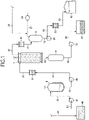
Fig. 1 is a flow diagram showing a main configuration of a treatment method for waste cleaning liquid and a treatment apparatus for waste cleaning liquid according to the present invention. -
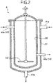
Fig. 2 is a longitudinal cross-sectional view showing a structure of a stirring tank as an example of stirring means for use in the present invention. -
Fig. 3 is a longitudinal cross-sectional view showing a structure of an example of a thin film evaporator as evaporation separating means for use in the present invention. - Referring to the drawings, a description will be given of an embodiment of a treatment apparatus for waste cleaning liquid (hereinafter, abbreviated as a "treatment apparatus") according to the present invention and a treatment method for waste cleaning liquid using the treatment apparatus (hereinafter, abbreviated as a "treatment method") according to the present invention.
- The present invention is applied in order to treat a waste cleaning liquid discharged from a process of producing an electrode of a lithium-ion secondary battery. The above-described waste cleaning liquid is a suspension of an electrode material that is a solid component and of a cleaning liquid, and the waste cleaning liquid discharged from a preparation tank in a positive electrode production process contains the NMP for use in cleaning as a main component, and a solid component and a binder contained in the electrode material. Moreover, a waste cleaning liquid discharged from a preparation tank in a negative electrode production process includes water for use in cleaning as a main component, and a solid component and a binder contained in the electrode material.
- First, the treatment apparatus of the present invention will be described. The treatment apparatus of the present invention is applied for each of the waste cleaning liquids discharged from the respective electrode production steps. In the following embodiment, a description will be given of an example of the treatment apparatus applied to the treatment of the waste cleaning liquid that is discharged from the positive electrode production process and contains the NMP. Note that, in
Figs. 1 to 3 showing the treatment apparatus, valves, a thermometer, a liquid level gauge and a control device are omitted. - As shown in
Fig. 1 , the treatment apparatus of the present invention includes: stirring means for stirring the-waste cleaning liquid introduced from the electrode production process; a liquid feed line that takes out the waste cleaning liquid from the stirring means; and evaporation separating means for evaporating the cleaning liquid in the waste cleaning liquid to separate the solid component, the evaporation separating means being supplied with the waste cleaning liquid by the liquid feed line, in which the waste cleaning liquid is supplied to the evaporation separating means by the liquid feed line while stirring the waste cleaning liquid by the stirring means. - In usual, in a subsequent stage to the electrode production process, the waste cleaning liquid is reserved in a conventional
portable container 40 from a preparation tank (not shown) of a coating apparatus through aflow path 10 for discharging the waste cleaning liquid. Then, in the treatment apparatus, through a subject liquid supply line constituted of aflow path 11, apump 31 and aflow path 12, the waste cleaning liquid is introduced into the above-described stirring means from theportable container 40. - As the stirring means, a stirring tank 6 as shown is mentioned. As will be described later, the stirring tank 6 is disposed in order to disperse the solid component in the waste cleaning liquid supplied to the above-described evaporation separating means. As the stirring tank 6, a tank having an appropriate structure can be used as long as it is provided with a stirring device such as a rotating wing or a screw capable of stirring the waste cleaning liquid. Further, preferably, the stirring tank 6 includes heating means in order to increase fluidity of the waste cleaning liquid supplied to the above-described evaporation separating means.
- Specifically, as shown in
Fig. 2 , the stirring tank 6 includes: atank body 60 having a stirringwing 62 therein; and a heating instrument, for example, ajacket 61 disposed on an outer circumferential portion of the tank body. Thetank body 60 is a hermetically sealed container with an approximate internal capacity of 5 to 20 m3, is provided, on an upper end side thereof, with a subjectliquid inlet 60a into which the above-describedflow path 12 is connected, and is provided, on a lower end side thereof, with a subjectliquid outlet 60b into which aflow path 13 to be described later is connected. The stirringwing 62 disposed in a vicinity of a bottom portion of thetank body 60 is configured to be rotatable by a drive shaft inserted from an upper end of thetank body 60. Thejacket 61 is a heating oven that circulates vapor as a heating medium on the outer circumferential portion of thetank body 60, is provided with a heatingmedium supply port 61a on an upper end portion thereof, and is provided with a heating medium discharge port (drain) 61b on a lower end portion thereof. - Further, though not shown, the stirring tank as the stirring means may include a stirring device with another structure. For example, in the tank body, the stirring tank may include a circulation line by a pump. Such a stirring device by a pump is constituted by connecting sequentially a flow path that drains the waste cleaning liquid from the bottom portion of the tank body, a pump and a flow path that recirculates the waste cleaning liquid to an upper portion of the tank body. Further, like the above-described stirring tank 6, preferably, the stirring tank includes heating means such as a jacket disposed on an outer circumferential portion of the tank body, and is constituted to be capable of heating the waste cleaning liquid in the above-described tank body. Further, as the stirring means, a screw pump that transfers the suspension while stirring the same, or the like can also be used.
- Note that, as the heating means in the above-described stirring means, a variety of heat exchangers such as a heater disposed in the inside can be used as well as such an instrument as the jacket, which is disposed on the outer circumferential portion of the tank. Then, though not shown, the waste cleaning liquid is heated up to a predetermined temperature by the above-described heating means. For example, the temperature of the waste cleaning liquid in the
tank body 60 is detected by a temperature sensor provided in the stirring tank 6 and the control device of the treatment apparatus, and the heating means is constituted to be capable of heating the waste cleaning liquid in thetank body 60 to 40 to 90°C, preferably 70 to 90°C. - As shown in
Fig. 1 , the above-described liquid feed line that takes out the waste cleaning liquid from the stirring tank 6 and supplies the same to the above-described evaporation separating means is constituted of theflow path 13, apump 32, aflow path 14, and aflow path 15. Moreover, in order to increase the fluidity of the waste cleaning liquid supplied to the evaporation separating means and to approximate the temperature of the waste cleaning liquid to the evaporation temperature, preferably, the liquid feed line is added with aheating device 51 downstream of thepump 32, that is, between theflow path 14 and theflow path 15. By such aheating device 51, the waste cleaning liquid to be fed is made capable of being heated to 60 to 100°C, preferably 80 to 100°C. Note that a variety of heat exchangers including a spiral-type one can be used as theheating device 51. - Incidentally, in the case of collecting the waste cleaning liquid containing the NMP by evaporation, preferably, the waste cleaning liquid is evaporated at a temperature as low as possible and for a residence time as short as possible in order to suppress a high-boiling-point component and a peroxide from being generated. Accordingly, in the present invention, a thin film evaporator as an example, is used as the above-described evaporation separating means for evaporating the waste cleaning liquid and separating the solid component. The thin film evaporator is a known device that forms a thin film of a subject liquid on an evaporation surface and heats the same and performs purification, enrichment and the like of the subject liquid. In usual, the thin film evaporator is operated under a reduced pressure condition, and can evaporate a liquid component at a relatively low temperature. Specifically, the downflow-type
thin film evaporator 7 shown inFig. 3 is used as such a thin film evaporator. - The
thin film evaporator 7 shown inFig. 3 includes: acylindrical evaporator body 70 supplied with the waste cleaning liquid from one end portion thereof arotating blade 72 disposed along a centerline of the evaporator body; and heating means disposed on an outer circumferential portion of theevaporator body 70. Thethin film evaporator 7 is provided with a structure to form a thin film of the waste cleaning liquid that is the subject liquid on an inner circumferential surface of theevaporator body 70, and to scrape off a remaining solid component by therotating blade 72 and discharge them from other end portion of theevaporator body 70. - In the
thin film evaporator 7, theevaporator body 70 is a metallic cylindrical container with an approximate heat transfer area of 2 to 10 m2, and the inner circumferential surface thereof is used as the evaporation surface. An upper end portion of theevaporator body 70 is constituted as a subject liquid supply/discharge portion. The waste cleaning liquid is supplied through a subjectliquid inlet 70a connected to theflow path 15, and the vapor (NMP) separated from the waste cleaning liquid is discharged through avapor outlet 70b connected to theflow path 16. - The
rotating blade 72 is disposed in a spiral shape as an example along adrive shaft 73 inserted into the center of theevaporator body 70, and a tip end portion of therotating blade 72 is constituted in a state of substantially contacting the inner circumferential surface of theevaporator body 70. Thedrive shaft 73 is supported by a bearing provided in an upper lid 74 on the upper end of theevaporator body 70, and by a bearing provided in abottom lid 75 on the lower end of theevaporator body 70. Moreover, thebottom lid 75 is provided withslits 75c which drop the solid component that is sludge downward, and thethin film evaporator 7 is constituted to discharge the solid component from asludge discharge port 76 connected to aflow path 23 to be described later. - As the heating means on the outer circumferential portion of the
evaporator body 70, in usual, used is ajacket 71 that circulates vapor as a heating medium. Like the above-mentioned stirring tank 6, thejacket 71 is a heating oven that circulates the vapor of theevaporator body 70, and is provided with aheating fluid inlet 71a on an upper end portion thereof, and is provided with a heating fluid outlet (drain) 71b on a lower end portion thereof. - As shown in
Fig. 1 , in the treatment apparatus, in order to reduce a pressure in a system thereof by avacuum pump 34 to be described later, the solid component separated by thethin film evaporator 7 is taken out into asludge collection container 8 through theflow path 23 and is tentatively reserved therein. Then, aflow path 24, apump 35, and aflow path 25, which constitute an unloading line, are connected to a bottom portion of thesludge collection container 8. Through the unloading line, the solid component in thesludge collection container 8 is transferred to aportable container 41 for unloading. - Meanwhile, the above-mentioned
flow path 16 as a vapor collection line is connected to the subject liquid supply/discharge portion of the above-describedthin film evaporator 7, and acondenser 52 is disposed downstream of theflow path 16. Then, in the treatment apparatus, the vapor of the NMP separated by thethin film evaporator 7 is liquefied by thecondenser 52, and the liquefied NMP is collected to a separatedliquid collection container 9 through theflow path 17. Note that a variety of heat exchangers such as a multi-pipe-type heat exchanger can be used as thecondenser 52. - Like the above-mentioned
sludge collection container 8, the separatedliquid collection container 9 is disposed in order to maintain the inside of the system in a pressure reduction state. A liquid withdrawal line constituted of aflow path 18, apump 33, aflow path 19, a cooler 53, and aflow path 20 is connected to a bottom portion of the separatedliquid collection container 9. In the treatment apparatus, the NMP in the separatedliquid collection container 9 is stored in a collectedliquid storage tank 42 through the liquid withdrawal line. The cooler 53 is disposed in order to cool, to room temperature, the NMP stored in the collectedliquid storage tank 42. As the cooler 53, a variety of heat exchangers such as a multi-pipe-type heat exchanger can be used. - Moreover, in the treatment apparatus, in order to promote the evaporation in the
thin film evaporator 7 by reducing the pressure in the system of the treatment apparatus itself, for example, an upper portion of the separatedliquid collection container 9 is connected to thevacuum pump 34 through aflow path 21. Further, in order to prevent the invasion of air into the system, and to suppress the generation of the peroxide in the NMP, aflow path 22 for supplying inert gas such as nitrogen is connected, for example, to the above-describedflow path 21. - Next, the treatment method of the present invention, which uses the above-described treatment apparatus, will be described. The waste cleaning liquid discharged from the electrode production process, for example, such a waste cleaning liquid that is discharged from the coating apparatus in the positive electrode production process and contains the NMP as a main component is reserved in the
portable container 40 through theflow path 10. - In the treatment method of the present invention, first, the waste cleaning liquid in the
portable container 40 is introduced into the stirring tank 6 as an example of stirring means through theflow path 11, thepump 31 and theflow path 12. An introduction amount of the waste cleaning liquid into the stirring tank 6 is set, for example, to 100 to 500 kg/hour though the introduction amount varies depending on a scale of the electrode production process. Moreover, when the treatment apparatus is operated, thevacuum pump 34 is actuated to reduce the pressure in the system to 1 to 10 kPaA while supplying nitrogen as an example into the system through theflow path 22. - Subsequently, when a liquid level of the waste cleaning liquid reaches a predetermined height in the stirring tank 6, the stirring
wing 62 is rotated to stir the waste cleaning liquid, whereby the solid component in the waste cleaning liquid is diffused. Moreover, at the same time, the vapor for heating is supplied to thejacket 61 to heat the-waste cleaning liquid in the stirring tank 6 to 40 to 90°C, preferably, 70 to 90°C. Thus, the fluidity of the waste cleaning liquid can be increased to approximate the temperature thereof to the evaporation temperature. Then, while being stirred in the stirring tank 6, the waste cleaning liquid is supplied to thethin film evaporator 7 as evaporation separating means through theflow path 13, thepump 32, theflow path 14 and theflow path 15, which constitute the liquid feed line. - Moreover, when the waste cleaning liquid is supplied to the
thin film evaporator 7, then in the above-described liquid feed line, the waste cleaning liquid is further heated to 60 to 100°C, preferably 80 to 100°C by theheating device 51. Thus, the fluidity of the waste cleaning liquid can be maintained, and the temperature of the waste cleaning liquid can be further approximated to the evaporation temperature. That is, in the treatment method of the present invention, the waste cleaning liquid is supplied to thethin film evaporator 7 in a state in which the solid component in the waste cleaning liquid is diffused and viscosity of the waste cleaning liquid is decreased, whereby the blockages in the flow paths and the instruments are prevented. In addition, the waste cleaning liquid is supplied to thethin film evaporator 7 in a state in which the temperature of the waste cleaning liquid is approximated to the evaporation temperature, whereby the function of thethin film evaporator 7 is sufficiently exerted. - In the
thin film evaporator 7, therotating blade 72 is rotated while the waste cleaning liquid is being supplied to theevaporator body 70. Moreover, at that time, the vapor for heating is supplied to thejacket 71, and theevaporator body 70 is heated, for example, to 100 to 130°C. Thus, in thethin film evaporator 7, the thin film of the waste cleaning liquid is formed on the inner surface of theevaporator body 70, and the evaporation of the cleaning liquid is accelerated. In the treatment method of the present invention, as described above, the waste cleaning liquid supplied to thethin film evaporator 7 is stirred and heated to approximate the temperature thereof to the evaporation temperature. Accordingly, the evaporation efficiency in thethin film evaporator 7 can be further increased. - In the
thin film evaporator 7, the thin film of the waste cleaning liquid is formed as described above, whereby the cleaning liquid in the waste cleaning liquid is evaporated to separate the solid component. Then, the separated solid component is continuously scrapped off by therotating blade 72, and is discharged downward from theevaporator body 70 through thesludge discharge port 76. Moreover, the NMP obtained by the evaporation is collected from thevapor outlet 70b in the upper end of theevaporator body 70. - The solid component discharged from the
thin film evaporator 7 by such an evaporation separating operation of thethin film evaporator 7, that is, the solid component containing the electrode material is collected to thesludge collection container 8 through theflow path 23. The solid component collected to thesludge collection container 8 can be taken out to theportable container 41 as an example through the unloading line constituted of theflow path 24, thepump 35, and theflow path 25. - Moreover, the vapor collected from the
thin film evaporator 7 by the evaporation separating operation of thethin film evaporator 7, that is, the vapor of the NMP is introduced into thecondenser 52 through theflow path 16 and is liquefied in the condenser, and in addition, the liquid NMP is reserved in the separatedliquid collection container 9 through theflow path 17. Then, the NMP in the separatedliquid collection container 9 can be stored in the collectedliquid storage tank 42 through theflow path 18, thepump 33, theflow path 19, and theflow path 20. Moreover, when the liquid is fed to the collectedliquid storage tank 42, the NMP is cooled down to room temperature by the cooler 53 interposed between theflow path 19 and theflow path 20. The NMP in the collectedliquid storage tank 42 can be reused by further being purified by a variety of conventional evaporation methods. - As described above, in the present invention, the waste cleaning liquid is stirred in advance in the stirring tank 6 to evenly diffuse the solid component, and is supplied to the
thin film evaporator 7 that is the evaporation separating means in a state in which the solid component is diffused. Accordingly, the solid component can be prevented from being retained and adhered in and to the flow paths and the devices, and the instruments can be prevented from being blocked by the solid component. Moreover, when the waste cleaning liquid is supplied to thethin film evaporator 7, the waste cleaning liquid is heated up to a predetermined temperature in addition to the stirring of the waste cleaning liquid, whereby the viscosity of the waste cleaning liquid is decreased. Accordingly, the solid component can be further suppressed from being retained in the flow paths and the devices. In addition, the temperature of the waste cleaning liquid is raised, whereby the evaporation efficiency in thethin film evaporator 7 can be improved. Accordingly, the separation efficiency of the liquid component and the solid component can be increased, and the high-boiling-point component and the peroxide can be suppressed from being generated. Further, in accordance with the present invention, the volume reduction treatment of the waste liquid becomes more possible, and accordingly, production cost of the electrode can be further reduced. - Note that, similarly to the treatment of the waste cleaning liquid discharged from the positive electrode production process as described above, the present invention can also be applied to treatment of a waste cleaning liquid that is discharged from the negative electrode production process and contains water as a cleaning liquid. Since water can be collected by the evaporation separating means, this can be treated with ease without affecting an environment, and in the same way, the volume reduction treatment of the waste liquid can be further implemented.
- The waste cleaning liquid discharged from the preparation tank in the positive electrode production process was treated by the apparatus in
Fig. 1 , and an experiment was performed, in which the NMP was separated and collected, and a residue containing the electrode material was collected. A heat transfer area (a substantial evaporation area) in theevaporator body 70 of thethin film evaporator 7 was set to 0.5 m2. Then, the NMP collected to the separatedliquid collection container 9 was weighed, and a volume reduction rate of the waste cleaning liquid was confirmed. Main operation conditions and the volume reduction rate are as shown in Table 1, and blockages in pipes and instruments during the operation were not recognized. - The waste cleaning liquid discharged from the coating apparatus in the positive electrode production process was supplied to a
thin film evaporator 7 similar to that in Example, and was subjected to the evaporation separating treatment. At that time, a conveying line constituted of only flow paths and pumps was used, and the waste cleaning liquid was directly supplied to thethin film evaporator 7 to theportable container 40. Then, after the operation was started, the conveying line was blocked, and a continuous operation was not able to be performed.[Table 1] Example 1 Example 2 Treatment amount (ml/min) 100 to 140 160 to 230 Initial temperature of waste cleaning liquid (°C) 31 33 Operation pressure in system (kPaA) 6 6 Evaporation temperature when supplied to thin film evaporator (°C) 135 145 Operation temperature of thin film evaporator (°C) 95 95 Volume reduction rate (%) 90 90 - The treatment apparatus for waste cleaning liquid and the treatment method for waste cleaning liquid according to the present invention can efficiently separate the liquid component and the solid component from the suspension, can sufficiently collect the liquid component and can subject the liquid component to the volume reduction treatment, and accordingly, are suitable for the treatment of the waste cleaning liquid that is discharged from the process of producing the electrode of the lithium-ion secondary battery and contains the electrode material easy to precipitate.
-
- 40
- Portable container
- 41
- Portable container
- 51
- Heating device
- 52
- Condenser
- 53
- Cooler
- 6
- Stirring tank
- 60
- Tank body
- 61
- Jacket (heating means)
- 62
- Stirring wing (stirring means)
- 7
- Thin film evaporator (evaporation separating means)
- 70
- Evaporator body
- 71
- Jacket (heating means)
- 72
- Rotating blade
- 76
- Sludge discharge port
- 8
- Sludge collection container
- 9
- Separated liquid collection container
Claims (12)
- A treatment apparatus for waste cleaning liquid that treats a waste cleaning liquid discharged from a process of producing an electrode of a lithium-ion secondary battery, the waste cleaning liquid being a suspension of an electrode material that is a solid component and a cleaning liquid, the treatment apparatus for waste cleaning liquid including: stirring means for stirring the waste cleaning liquid introduced from the electrode production process; a liquid feed line that takes out the waste cleaning liquid from the stirring means; and evaporation separating means for evaporating the cleaning liquid in the waste cleaning liquid to separate the solid component, the evaporation separating means being supplied with the waste cleaning liquid by the liquid feed line, being characterized in that the waste cleaning liquid is supplied to the evaporation separating means by the liquid feed line while stirring the waste cleaning liquid by the stirring means.
- The treatment apparatus for waste cleaning liquid according to claim 1, being characterized in that the stirring means is a stirring tank having a stirring device in a tank body.
- The treatment apparatus for waste cleaning liquid according to claim 1, being characterized in that the stirring means is a stirring tank, and the stirring tank includes: a tank body having therein a stirring wing; and heating means disposed on an outer circumferential portion of the tank body, and is configured to be capable of heating the waste cleaning liquid in the tank body.
- The treatment apparatus for waste cleaning liquid according to claim 1, being characterized in that the stirring means is a stirring tank, and the stirring tank includes: a tank body having therein a stirring wing; and heating means disposed on an outer circumferential portion of the tank body, is configured to be capable of heating the waste cleaning liquid in the tank body, and is configured to be capable of heating the waste cleaning liquid to 40 to 90°C in the tank body.
- The treatment apparatus for waste cleaning liquid according to claim 1, being characterized in that the stirring means is a stirring tank, and the stirring tank includes: a tank body having a circulation line by a pump; and heating means disposed on an outer circumferential portion of the tank body, and is configured to be capable of heating the waste cleaning liquid in the tank body.
- The treatment apparatus for waste cleaning liquid according to claim 1, being characterized in that the stirring means is a stirring tank, and the stirring tank includes: a tank body having a circulation line by a pump; and heating means disposed on an outer circumferential portion of the tank body, is configured to be capable of heating the waste cleaning liquid in the tank body, and is configured to be capable of heating the waste cleaning liquid to 50 to 90°C in the tank body.
- The treatment apparatus for waste cleaning liquid according to claim 1, being characterized in that the evaporation separating means is a thin film evaporator.
- The treatment apparatus for waste cleaning liquid according to claim 1, being characterized in that the evaporation separating means is a thin film evaporator, and the thin film evaporator includes: a cylindrical evaporator body having one end portion from which the waste cleaning liquid is supplied; a rotating blade disposed along a centerline of the evaporator body; and heating means disposed on an outer circumferential portion of the evaporator body, and is provided with a structure to scrape off, by the rotating blade, a solid component adhered to an inner circumferential surface of the evaporator body and discharge the solid component from other end portion of the evaporator body.
- The treatment apparatus for waste cleaning liquid according to claim 1, being characterized in that the liquid feed line that takes out the waste cleaning liquid from the stirring tank and supplies the waste cleaning liquid to the evaporation separating means is added with a heating device, and the heating device is configured to be capable of heating, to 60 to 100°C, the waste cleaning liquid supplied to the evaporation separating means.
- The treatment apparatus for waste cleaning liquid according to claim 1, being characterized in that the waste cleaning liquid is a waste cleaning liquid containing a solid component that contains, as a main component, NMP used for cleaning and constitutes an electrode material.
- A treatment method for waste cleaning liquid of treating, by a treatment apparatus, a waste cleaning liquid discharged from a process of producing an electrode of a lithium-ion secondary battery, the waste cleaning liquid being a suspension of an electrode material that is a solid component and a cleaning liquid, being characterized in that the waste cleaning liquid treatment apparatus includes: stirring means for stirring the waste cleaning liquid introduced from the electrode production process; a liquid feed line that takes out the-waste cleaning liquid from the stirring means; and evaporation separating means for evaporating the cleaning liquid in the waste cleaning liquid to separate the solid component, the evaporation separating means being supplied with the waste cleaning liquid by the liquid feed line, and in the treatment method, the waste cleaning liquid is stirred by the stirring means, the waste cleaning liquid is supplied to the evaporation separating means in a state in which the solid component is diffused, and in the evaporation separating means, the cleaning liquid in the waste cleaning liquid is evaporated to separate the solid component.
- The treatment method for waste cleaning liquid according to claim 11, being characterized in that the waste cleaning liquid is a waste cleaning liquid containing a solid component that contains, as a main component, NMP used for cleaning and constitutes an electrode material.
Applications Claiming Priority (3)
| Application Number | Priority Date | Filing Date | Title |
|---|---|---|---|
| JP2019186434 | 2019-10-09 | ||
| JP2020159055A JP7524010B2 (en) | 2019-10-09 | 2020-09-23 | Treatment device for cleaning waste liquid and method for treating cleaning waste liquid |
| PCT/JP2020/036992 WO2021070689A1 (en) | 2019-10-09 | 2020-09-29 | Treatment apparatus for cleaning liquid waste and treatment method for cleaning liquid waste |
Publications (2)
| Publication Number | Publication Date |
|---|---|
| EP4015058A1 true EP4015058A1 (en) | 2022-06-22 |
| EP4015058A4 EP4015058A4 (en) | 2022-10-19 |
Family
ID=75381059
Family Applications (1)
| Application Number | Title | Priority Date | Filing Date |
|---|---|---|---|
| EP20875392.1A Pending EP4015058A4 (en) | 2019-10-09 | 2020-09-29 | TREATMENT APPARATUS FOR CLEANING LIQUID WASTE AND TREATMENT METHOD FOR CLEANING LIQUID WASTE |
Country Status (8)
| Country | Link |
|---|---|
| US (1) | US12053716B2 (en) |
| EP (1) | EP4015058A4 (en) |
| JP (1) | JP7524010B2 (en) |
| KR (1) | KR102808335B1 (en) |
| CN (1) | CN114514203B (en) |
| CA (1) | CA3154180C (en) |
| TW (1) | TWI836149B (en) |
| WO (1) | WO2021070689A1 (en) |
Families Citing this family (4)
| Publication number | Priority date | Publication date | Assignee | Title |
|---|---|---|---|---|
| CN113213573A (en) * | 2021-05-07 | 2021-08-06 | 江苏绿科生物技术有限公司 | Evaporation equipment for treating microbial fermentation waste liquid |
| EP4141009A1 (en) * | 2021-08-30 | 2023-03-01 | Saltigo GmbH | Method for the preparation of a mixture containing hydroxy-ethyl isobutyl piperidine carboxylate |
| CN115663327B (en) * | 2022-10-18 | 2026-03-03 | 雅邦绿色过程与新材料研究院南京有限公司 | Method for separating lithium salt and carbonate organic solvent from lithium battery waste electrolyte |
| KR20250174430A (en) * | 2024-06-05 | 2025-12-12 | 주식회사 엘지에너지솔루션 | Treatment method for cleaning liquid waste |
Family Cites Families (16)
| Publication number | Priority date | Publication date | Assignee | Title |
|---|---|---|---|---|
| US20050069820A1 (en) * | 2003-09-25 | 2005-03-31 | Fuji Photo Film Co., Ltd. | Thin film evaporating concentrator, method of evaporating and solidifying photographic waste solution, and reuse method of photographic waste solution |
| JP2005108531A (en) | 2003-09-29 | 2005-04-21 | Mitsubishi Chemicals Corp | Non-aqueous electrolyte preparation device and non-aqueous electrolyte manufacturing method |
| JP2007099690A (en) | 2005-10-05 | 2007-04-19 | Sumitomo Chemical Co Ltd | Purification method of N-methyl-2-pyrrolidone. |
| JP2010105257A (en) | 2008-10-30 | 2010-05-13 | Fujifilm Corp | Method of recovering additive and apparatus for the same |
| JP5471221B2 (en) | 2009-09-14 | 2014-04-16 | 三菱化学エンジニアリング株式会社 | NMP distillation equipment |
| WO2014142314A1 (en) | 2013-03-14 | 2014-09-18 | 日本化学産業株式会社 | Treatment process for a positive electrode active material for lithium-ion secondary battery |
| JP6066199B2 (en) * | 2013-05-27 | 2017-01-25 | 株式会社イズミフードマシナリ | mixer |
| JP6413351B2 (en) | 2013-06-19 | 2018-10-31 | 株式会社Gsユアサ | Electricity storage element |
| JP2015037778A (en) | 2013-08-19 | 2015-02-26 | 株式会社櫻製作所 | Slurry liquid thin film evaporation concentrated powder system and evaporation apparatus |
| CN204910838U (en) * | 2015-07-17 | 2015-12-30 | 山东石大胜华化工集团股份有限公司 | Falling film evaporator device of ester -interchange method production propylene glycol |
| US11170947B2 (en) * | 2016-02-26 | 2021-11-09 | Musashi Energy Solutions Co., Ltd. | Doping system, and method for manufacturing electrodes, batteries and capacitors |
| CN107098416A (en) * | 2017-06-29 | 2017-08-29 | 合众高科(北京)环保技术股份有限公司 | A kind of Waste Water Treatment and its method of wastewater treatment with buffer unit |
| CN107768764B (en) | 2017-10-19 | 2019-06-21 | 陈明海 | A kind of waste and old lithium ion battery recycling production ternary precursor technique |
| CN208038082U (en) * | 2017-10-31 | 2018-11-02 | 肥城金威机械有限公司 | The falling film evaporation device of waste water is cleaned for manufacturing lithium battery |
| CN208512541U (en) * | 2018-05-23 | 2019-02-19 | 合肥亚龙化工有限责任公司 | A kind of reaction kettle waste-water recovering treater |
| CN208382938U (en) | 2018-07-03 | 2019-01-15 | 安徽相源新能源有限公司 | A kind of lithium ion battery production NMP recycling can |
-
2020
- 2020-09-23 JP JP2020159055A patent/JP7524010B2/en active Active
- 2020-09-29 US US17/767,578 patent/US12053716B2/en active Active
- 2020-09-29 WO PCT/JP2020/036992 patent/WO2021070689A1/en not_active Ceased
- 2020-09-29 CN CN202080070236.6A patent/CN114514203B/en active Active
- 2020-09-29 KR KR1020227011382A patent/KR102808335B1/en active Active
- 2020-09-29 CA CA3154180A patent/CA3154180C/en active Active
- 2020-09-29 EP EP20875392.1A patent/EP4015058A4/en active Pending
- 2020-10-08 TW TW109134966A patent/TWI836149B/en active
Also Published As
| Publication number | Publication date |
|---|---|
| TWI836149B (en) | 2024-03-21 |
| CN114514203B (en) | 2023-12-19 |
| CA3154180A1 (en) | 2021-04-15 |
| EP4015058A4 (en) | 2022-10-19 |
| JP2021058878A (en) | 2021-04-15 |
| KR20220055489A (en) | 2022-05-03 |
| JP7524010B2 (en) | 2024-07-29 |
| TW202120163A (en) | 2021-06-01 |
| CN114514203A (en) | 2022-05-17 |
| US12053716B2 (en) | 2024-08-06 |
| CA3154180C (en) | 2023-11-28 |
| WO2021070689A1 (en) | 2021-04-15 |
| KR102808335B1 (en) | 2025-05-19 |
| US20220410027A1 (en) | 2022-12-29 |
Similar Documents
| Publication | Publication Date | Title |
|---|---|---|
| US12053716B2 (en) | Treatment apparatus for waste cleaning liquid and treatment method for waste cleaning liquid | |
| CN101306885B (en) | A resourceful treatment method for coking sulfur-containing wastewater | |
| CN102482213A (en) | Distillation unit for NMP | |
| US11710867B2 (en) | Method to open up electro chemical energy storage devices and thermal treatment system | |
| CN108568134A (en) | Cobaltous sulfate evaporation crystallization equipment and technique | |
| CN1322005A (en) | Method and device for regeneration of waste solvent | |
| CN204365129U (en) | Novel anticorrosion desulphurization plant | |
| CN212712783U (en) | Titanium tetrachloride refining production system | |
| CN103094158A (en) | Substrate treating apparatus and chemical recycling method | |
| CN115317942A (en) | Parallel type solid-containing mother liquor solvent continuous rectification recovery system and method and application thereof | |
| CN221771544U (en) | A NMP batch distillation equipment | |
| CN108641759A (en) | A kind of Blending on Line System and method of generative fuel oil | |
| CN220597094U (en) | Silane treatment fluid waste liquid recovery unit | |
| CN218306222U (en) | Flash distillation device for agricultural potassium nitrate preparation | |
| CN223504847U (en) | A polyethylene glycol purification device | |
| JP2008545403A (en) | Method and apparatus for preparing an ethanol / water mixture | |
| CN214829124U (en) | Evaporative crystallization system of high-salinity wastewater | |
| JP3186996B2 (en) | Method for continuous extraction of wood and apparatus used therefor | |
| CN216498441U (en) | Separation system of ammonia in 2-hydrazino-4-methylbenzothiazole production | |
| CN218636641U (en) | MMDS vacuum distillation purification equipment | |
| CN201990553U (en) | Resource recovery device for hanger stripping waste liquid in electroplating copper process | |
| EP4578526B1 (en) | Nmp batch distillation device and process | |
| CN207071288U (en) | A kind of intermittent wash separator | |
| CN218012764U (en) | Recovery system of ammonium bifluoride in waste residue that electrolysis nitrogen trifluoride produced | |
| CN214299939U (en) | A high-pressure separator device for crude benzene hydrorefining process |
Legal Events
| Date | Code | Title | Description |
|---|---|---|---|
| STAA | Information on the status of an ep patent application or granted ep patent |
Free format text: STATUS: THE INTERNATIONAL PUBLICATION HAS BEEN MADE |
|
| PUAI | Public reference made under article 153(3) epc to a published international application that has entered the european phase |
Free format text: ORIGINAL CODE: 0009012 |
|
| STAA | Information on the status of an ep patent application or granted ep patent |
Free format text: STATUS: REQUEST FOR EXAMINATION WAS MADE |
|
| 17P | Request for examination filed |
Effective date: 20220314 |
|
| AK | Designated contracting states |
Kind code of ref document: A1 Designated state(s): AL AT BE BG CH CY CZ DE DK EE ES FI FR GB GR HR HU IE IS IT LI LT LU LV MC MK MT NL NO PL PT RO RS SE SI SK SM TR |
|
| A4 | Supplementary search report drawn up and despatched |
Effective date: 20220919 |
|
| RIC1 | Information provided on ipc code assigned before grant |
Ipc: H01M 10/058 20100101ALN20220913BHEP Ipc: C07D 207/267 20060101ALI20220913BHEP Ipc: B01D 1/22 20060101AFI20220913BHEP |
|
| DAV | Request for validation of the european patent (deleted) | ||
| DAX | Request for extension of the european patent (deleted) |