EP4015056A1 - Interlocking modular block - Google Patents
Interlocking modular block Download PDFInfo
- Publication number
- EP4015056A1 EP4015056A1 EP20214418.4A EP20214418A EP4015056A1 EP 4015056 A1 EP4015056 A1 EP 4015056A1 EP 20214418 A EP20214418 A EP 20214418A EP 4015056 A1 EP4015056 A1 EP 4015056A1
- Authority
- EP
- European Patent Office
- Prior art keywords
- block
- mortise
- tenon
- coupling
- spring element
- Prior art date
- Legal status (The legal status is an assumption and is not a legal conclusion. Google has not performed a legal analysis and makes no representation as to the accuracy of the status listed.)
- Granted
Links
Images


Classifications
-
- A—HUMAN NECESSITIES
- A63—SPORTS; GAMES; AMUSEMENTS
- A63H—TOYS, e.g. TOPS, DOLLS, HOOPS OR BUILDING BLOCKS
- A63H33/00—Other toys
- A63H33/04—Building blocks, strips, or similar building parts
- A63H33/06—Building blocks, strips, or similar building parts to be assembled without the use of additional elements
- A63H33/065—Building blocks, strips, or similar building parts to be assembled without the use of additional elements using elastic deformation
-
- A—HUMAN NECESSITIES
- A63—SPORTS; GAMES; AMUSEMENTS
- A63H—TOYS, e.g. TOPS, DOLLS, HOOPS OR BUILDING BLOCKS
- A63H33/00—Other toys
- A63H33/04—Building blocks, strips, or similar building parts
- A63H33/06—Building blocks, strips, or similar building parts to be assembled without the use of additional elements
- A63H33/08—Building blocks, strips, or similar building parts to be assembled without the use of additional elements provided with complementary holes, grooves, or protuberances, e.g. dovetails
- A63H33/086—Building blocks, strips, or similar building parts to be assembled without the use of additional elements provided with complementary holes, grooves, or protuberances, e.g. dovetails with primary projections fitting by friction in complementary spaces between secondary projections, e.g. sidewalls
Definitions
- the present invention relates to a set of interlocking modular block, intended mainly for the construction of three-dimensional models.
- the blocks are made of wood. They can be attached one to another in a way enabling them to be detached at a later stage without the need of any tools.
- Lego blocks which are made of plastic and include cylindrical plug type connection to enable detachment. Such a connection cannot be made of wood, as this would not function with wood.
- document WO0102073 describes construction blocks with a pin type connection, where the construction blocks have apertures for inserting and fixing the pin.
- the pin has an end stop for fixing and a longitudinal slot extending from the end, which is pressed together for inserting the block through the aperture, so that the stop fits through the aperture.
- the slot will open after passing the aperture, and the stop will remain on the other side for blocking the aperture.
- Document WO9015906 describes a modular assembly essentially made up of interlocking and modular planar panels. It also includes assembly elements which can be fitted into the ends of the panels, or in lateral notches made in said panels, which make it possible to attach them one to the other, preferably in a way enabling them to be detached at a later stage.
- the panels are approximately H-shaped, forming a male connector with two branches at the lower edge of the panel, and a corresponding female connector at its upper edge.
- a central cavity within this section opens onto the lower edge and the two ends of the panels.
- lateral notches are set alternatively between the central cavity and one or another of the panels surfaces at regular intervals in which are fitted the L- or T-shaped assembly elements. This provides a flexible assembly of modular elements which can be used for the partitioning of drawers, for developing constructional toys, or in the fitting-out out of a room or an exhibition stand.
- the object of the invention is to provide a set of modular blocks enabling smooth coupling, ensuring a strong connection between the blocks, while enabling also smooth attachment and detachment of blocks.
- Such a connection is achieved, contrary to the solutions of the prior art, by pressing open the material layer surrounding the mortise, which forms the spring element, with the tenon, when the tenon enters the mortise.
- the spring element surrounding the mortise has two symmetric cutouts, which enable movement/deformation of the material layer. Wood fibres of the material layer are parallel to the tenon axis, enabling deformation of wood.
- the coupling block has a shape of a cuboid and it has four lateral surfaces, bottom surface and upper surface.
- the cuboid has at least one cylindrical through aperture. The cylindrical aperture starts from the bottom surface and exits from the upper surface of the cuboid.
- the cylindrical aperture has larger diameter in the lower part and forms the mortise.
- the diameter of the cylindrical part decreases conically in the central part of the cuboid, whereby in the upper part of the cuboid, the diameter of the cylindrical part is smaller than in the lower part.
- the cylindrical aperture is surrounded by a cylindrical groove, forming a cylindrical aperture around the material layer.
- the cylindrical groove does not reach through the cuboid, forming the upper and lower cylindrical groove.
- the upper and lower cylindrical groove end in the central part of the cuboid.
- the central part of the cylinder includes cuboid material, which is part of the cuboid and connected with the spring element.
- the upper part of the cylindrical aperture with the material layer forms the tenon.
- the lower part of the cylindrical aperture surrounded by the spring element forms the mortise.
- Two cutouts are made in the spring element surrounding the lower part of the cylindrical aperture, so that the cylindrical aperture is connected to the lower cylindrical groove. Edges of both cutouts are parallel and oriented upwards in extent of the entire spring element forming the mortise.
- the cylindrical aperture is surrounded by material forming the tenon and extending over the upper surface of the cuboid. Thickness of the material surrounding the upper cylindrical aperture differs from the thickness of the material extending from the cuboid and located in the inner part of the cuboid, so that the inner part has a larger diameter. The thickness of the material layer extending over the upper surface of the cuboid is lower than thickness of the material layer extending to the upper surface of the cuboid.
- the diameter of the lower part of the cylindrical aperture is less by the value a than the external diameter of the material layer extending from the upper part of the cylindrical aperture over the upper surface of the cuboid, i.e. the tenon, forming interference fit.
- Interference coefficient is in the range from 1.03 to 1.06, preferably 1.05.
- the material layer extending over the upper surface of the cuboid/tenon enters the lower cylindrical aperture/mortise of the other coupling block, forming mortise and tenon joint.
- the coupling block is made of three-layer laminated timber, whereby in the central part of the block, the wood fibers are oriented downwards parallel to the tenon axis, and in the edges of the block, the wood fibers are perpendicular to the downwards direction.
- Direction of fibers in the central layer follows the vertically upwards direction of the cylindrical aperture.
- Timber is a homogeneous material and the high flexibility of the material is achieved in result of external force applied on the longitudinal axis of the texture. Due to such a property of timber, the part projecting from the upper surface of the lower block will couple strongly into the lower cylindrical aperture of the block placed onto it.
- Figure 1 is a top view of a coupling block 1 showing the upper surface 2 of the block, upper cylindrical groove 3, cylindrical aperture 5, which form the tendon 4 with the upper material layer.
- Figure 2 is a view of section A - A of the coupling block 1 of Figure 1 .
- the coupling block 1 has a cuboid shape and it has four lateral surfaces 7, bottom surface 14, and upper surface 2.
- the coupling block 1 has at least one through cylindrical aperture 5.
- the cylindrical aperture 5 starts from the bottom surface 14 and exits from the upper surface 2 of the cuboid.
- the cylindrical aperture 5 has a larger diameter in the lower part than in the upper part and forms the mortise 11.
- the cylindrical aperture 5 is surrounded by the cylindrical groove 3 and 9, forming a cylindrical aperture around the material layer.
- the cylindrical groove does not reach through the coupling block 1, forming upper cylindrical groove 3 and lower cylindrical groove 9.
- Upper cylindrical groove 3 and lower cylindrical groove 9 end in the central part of the coupling block.
- the central part of the cylinder includes material of the coupling block 1, which is part of the cuboid and connected with the material layer surrounding the tenon 4 and the mortise 11, forming the spring element 10.
- the upper part of the cylindrical aperture 5 with the material layer forms the tenon 4.
- the lower part of the cylindrical aperture 5 surrounded by the spring element 10 forms the mortise 11.
- the upper cylindrical groove 3 is necessary for making the tenon 4 and upper part of the block 1, providing advantage during drilling for fixing the cutting blades in material.
- a further task of the upper cylindrical groove 3 is to ensure that the mortise and tenon joint is free of dust and debris to enable insertion of the tenon 4 completely into the mortise 11.
- Two cutouts 12 are made in the spring element 10 surrounding the lower part of the cylindrical aperture 5, so that the cylindrical aperture 5 is connected to the lower cylindrical groove 9. Edges of both cutouts 12 are parallel and oriented upwards. Stroke force of the spring element 10 depends on the size of the cutout 12. If the cutout 12 is wider, the force of the spring is weaker, while narrower cutout ensures higher force of the spring. Optimal compressive strength is determined empirically. The cutout 12 provides strength to the spring element 10. The size of a cutout is based on material, being different in the case of different timber species. It is larger in the case of species with a higher density, such as birch and beech.
- the upper part of the cylindrical aperture 5 is surrounded by material forming the tenon 4 and extending over the upper surface 2 of the cuboid.
- the thickness of the material surrounding the upper part of the cylindrical aperture 5 differs from the thickness of the material extending from the block 1 and located in the inner part of the block 1, so that the inner part has a larger diameter.
- the thickness of the material layer extending over the upper surface 2 of the coupling block 1 is lower than thickness of the material layer extending to the upper surface of the cuboid by step 6.
- Figure 3 is a bottom view of a coupling block 1, showing the formation of the mortise 11.
- the mortise 11 is formed between two material layers 10 surrounding the mortise. Material layers 11 have a curved shape and are surrounded by lower cylindrical groove 9. Material layers 11 are separated by the cutout 12. The cutout 12 is needed to ensure radial deformation of the material layers 11, when the tenon 4 is inserted into the mortise 11.
- Figure 4 illustrates the connection between two coupling blocks 1, where upon connection of the blocks, the tenon 4 of one coupling block 1 enters the mortise 11 formed in the lower part of the other block 1.
- the diameter of the lower part of the cylindrical aperture 5 is less by the value a than the external diameter of the material layer extending from the upper part of the cylindrical aperture 5 over the upper surface of the cuboid, i.e. the tenon 4, forming interference fit.
- Interference coefficient is in the range from 1.03 to 1.06, preferably 1.05.
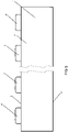
- Figure 5 is a side view of a coupling block 1, showing that the block 1 may have plurality of tenons for coupling. All tenons are axially aligned with determined intervals to ensure the possibility of coupling with another block.
- the figure shows lateral surface 7, bottom surface 14, upper surface 2 of the coupling block 1, and tenons 4 located higher than the upper surface 2.
- the coupling block 1 is made of three-layer laminated timber, whereby in the central part of the block 1, the wood fibers are oriented downwards along the longitudinal axis 8 of the tenon, and in the edges of the block 1, the wood fibers are perpendicular to the downwards direction.
- the direction of fibers in the central layer follows the vertically upwards direction of the cylindrical aperture 5.
- the mortise 11 and the tenon 4 with all accompanying elements are made by milling.
- the blocks are designated mainly for constructing architectural models. Also for construction three-dimensional models by placing on the upper surface 2 of one block the bottom surface 14 of the other block, so that tenons 4 are aligned with mortises 11. When blocks are gently pushed, tenons 4 will enter the mortises 11 and blocks 1 are smoothly coupled to each other. In order to detach blocks 1 from each other, blocks 1 shall be pulled carefully in the direction of longitudinal axis 8.
- the through aperture 5 in a block enables attaching a block to another block without causing any air resistance to be overcome.
- Coupling blocks 1 are designed so that they may have different number of tenons. This enables to use them for constructing various different three-dimensional models. Coupling blocks are also well suitable for use as playing blocks for children. The scope of use of the coupling blocks is broader than specified herein.
Landscapes
- Toys (AREA)
- Joining Of Building Structures In Genera (AREA)
Abstract
Description
- The present invention relates to a set of interlocking modular block, intended mainly for the construction of three-dimensional models. The blocks are made of wood. They can be attached one to another in a way enabling them to be detached at a later stage without the need of any tools.
- Various different construction blocks are known in the prior art, for use, for example, as children's toys. The most well-known are Lego blocks, which are made of plastic and include cylindrical plug type connection to enable detachment. Such a connection cannot be made of wood, as this would not function with wood.
- In addition, construction blocks with pin type connection are known in the prior art.
- For example, document
WO0102073 - Document
WO9015906 - In both mentioned documents, a physical extending stop with a triangular cross section is needed for maintaining the connection. Such a connection is not smooth and causes problems during attachment and detachment.
- The object of the invention is to provide a set of modular blocks enabling smooth coupling, ensuring a strong connection between the blocks, while enabling also smooth attachment and detachment of blocks. Such a connection is achieved, contrary to the solutions of the prior art, by pressing open the material layer surrounding the mortise, which forms the spring element, with the tenon, when the tenon enters the mortise. The spring element surrounding the mortise has two symmetric cutouts, which enable movement/deformation of the material layer. Wood fibres of the material layer are parallel to the tenon axis, enabling deformation of wood.
- The characteristic ability of wood to restore its initial shape after deformation ensures a strong connection.
- The coupling block has a shape of a cuboid and it has four lateral surfaces, bottom surface and upper surface. The cuboid has at least one cylindrical through aperture. The cylindrical aperture starts from the bottom surface and exits from the upper surface of the cuboid.
- The cylindrical aperture has larger diameter in the lower part and forms the mortise. The diameter of the cylindrical part decreases conically in the central part of the cuboid, whereby in the upper part of the cuboid, the diameter of the cylindrical part is smaller than in the lower part.
- On the upper and lower part of the cuboid, the cylindrical aperture is surrounded by a cylindrical groove, forming a cylindrical aperture around the material layer. The cylindrical groove does not reach through the cuboid, forming the upper and lower cylindrical groove. The upper and lower cylindrical groove end in the central part of the cuboid. The central part of the cylinder includes cuboid material, which is part of the cuboid and connected with the spring element.
- The upper part of the cylindrical aperture with the material layer forms the tenon. The lower part of the cylindrical aperture surrounded by the spring element forms the mortise. When connecting the blocks, the tenon of one block enters the mortise formed in the lower part of the other block.
- Two cutouts are made in the spring element surrounding the lower part of the cylindrical aperture, so that the cylindrical aperture is connected to the lower cylindrical groove. Edges of both cutouts are parallel and oriented upwards in extent of the entire spring element forming the mortise.
- In the upper part, the cylindrical aperture is surrounded by material forming the tenon and extending over the upper surface of the cuboid. Thickness of the material surrounding the upper cylindrical aperture differs from the thickness of the material extending from the cuboid and located in the inner part of the cuboid, so that the inner part has a larger diameter. The thickness of the material layer extending over the upper surface of the cuboid is lower than thickness of the material layer extending to the upper surface of the cuboid.
- The diameter of the lower part of the cylindrical aperture is less by the value a than the external diameter of the material layer extending from the upper part of the cylindrical aperture over the upper surface of the cuboid, i.e. the tenon, forming interference fit. Interference coefficient is in the range from 1.03 to 1.06, preferably 1.05.
- The material layer extending over the upper surface of the cuboid/tenon enters the lower cylindrical aperture/mortise of the other coupling block, forming mortise and tenon joint.
- The coupling block is made of three-layer laminated timber, whereby in the central part of the block, the wood fibers are oriented downwards parallel to the tenon axis, and in the edges of the block, the wood fibers are perpendicular to the downwards direction. Direction of fibers in the central layer follows the vertically upwards direction of the cylindrical aperture.
- Timber is a homogeneous material and the high flexibility of the material is achieved in result of external force applied on the longitudinal axis of the texture. Due to such a property of timber, the part projecting from the upper surface of the lower block will couple strongly into the lower cylindrical aperture of the block placed onto it.
- The above mentioned and other features and advantages of the present invention will be described in detail below with reference to the appended figures illustrating the preferred embodiments, where
-
Figure 1 is a top view of a coupling block -
Figure 2 is a view of section A - A of the coupling block ofFigure 1 -
Figure 3 is a bottom view of a coupling block -
Figure 4 is a view of a section of two coupling blocks, where the tenon of the lower block is in the mortise of the upper block -
Figure 5 is a side view of a coupling block, where the block has plurality of tendons. -
Figure 1 is a top view of acoupling block 1 showing theupper surface 2 of the block, uppercylindrical groove 3,cylindrical aperture 5, which form thetendon 4 with the upper material layer. -
Figure 2 is a view of section A - A of thecoupling block 1 ofFigure 1 . Thecoupling block 1 has a cuboid shape and it has fourlateral surfaces 7,bottom surface 14, andupper surface 2. Thecoupling block 1 has at least one throughcylindrical aperture 5. Thecylindrical aperture 5 starts from thebottom surface 14 and exits from theupper surface 2 of the cuboid. - The
cylindrical aperture 5 has a larger diameter in the lower part than in the upper part and forms themortise 11. - The
cylindrical aperture 5 is surrounded by thecylindrical groove coupling block 1, forming uppercylindrical groove 3 and lowercylindrical groove 9. Uppercylindrical groove 3 and lowercylindrical groove 9 end in the central part of the coupling block. The central part of the cylinder includes material of thecoupling block 1, which is part of the cuboid and connected with the material layer surrounding thetenon 4 and themortise 11, forming thespring element 10. - The upper part of the
cylindrical aperture 5 with the material layer forms thetenon 4. The lower part of thecylindrical aperture 5 surrounded by thespring element 10 forms themortise 11. - The upper
cylindrical groove 3 is necessary for making thetenon 4 and upper part of theblock 1, providing advantage during drilling for fixing the cutting blades in material. - A further task of the upper
cylindrical groove 3 is to ensure that the mortise and tenon joint is free of dust and debris to enable insertion of thetenon 4 completely into themortise 11. - Two
cutouts 12 are made in thespring element 10 surrounding the lower part of thecylindrical aperture 5, so that thecylindrical aperture 5 is connected to the lowercylindrical groove 9. Edges of bothcutouts 12 are parallel and oriented upwards. Stroke force of thespring element 10 depends on the size of thecutout 12. If thecutout 12 is wider, the force of the spring is weaker, while narrower cutout ensures higher force of the spring. Optimal compressive strength is determined empirically. Thecutout 12 provides strength to thespring element 10. The size of a cutout is based on material, being different in the case of different timber species. It is larger in the case of species with a higher density, such as birch and beech. - The upper part of the
cylindrical aperture 5 is surrounded by material forming thetenon 4 and extending over theupper surface 2 of the cuboid. The thickness of the material surrounding the upper part of thecylindrical aperture 5 differs from the thickness of the material extending from theblock 1 and located in the inner part of theblock 1, so that the inner part has a larger diameter. The thickness of the material layer extending over theupper surface 2 of thecoupling block 1 is lower than thickness of the material layer extending to the upper surface of the cuboid bystep 6. -
Figure 3 is a bottom view of acoupling block 1, showing the formation of themortise 11. Themortise 11 is formed between twomaterial layers 10 surrounding the mortise. Material layers 11 have a curved shape and are surrounded by lowercylindrical groove 9. Material layers 11 are separated by thecutout 12. Thecutout 12 is needed to ensure radial deformation of the material layers 11, when thetenon 4 is inserted into themortise 11. -
Figure 4 illustrates the connection between twocoupling blocks 1, where upon connection of the blocks, thetenon 4 of onecoupling block 1 enters themortise 11 formed in the lower part of theother block 1. - The diameter of the lower part of the
cylindrical aperture 5 is less by the value a than the external diameter of the material layer extending from the upper part of thecylindrical aperture 5 over the upper surface of the cuboid, i.e. thetenon 4, forming interference fit. Interference coefficient is in the range from 1.03 to 1.06, preferably 1.05. -
Figure 5 is a side view of acoupling block 1, showing that theblock 1 may have plurality of tenons for coupling. All tenons are axially aligned with determined intervals to ensure the possibility of coupling with another block. The figure showslateral surface 7,bottom surface 14,upper surface 2 of thecoupling block 1, and tenons 4 located higher than theupper surface 2. - The
coupling block 1 is made of three-layer laminated timber, whereby in the central part of theblock 1, the wood fibers are oriented downwards along thelongitudinal axis 8 of the tenon, and in the edges of theblock 1, the wood fibers are perpendicular to the downwards direction. The direction of fibers in the central layer follows the vertically upwards direction of thecylindrical aperture 5. Themortise 11 and thetenon 4 with all accompanying elements are made by milling. - The blocks are designated mainly for constructing architectural models. Also for construction three-dimensional models by placing on the
upper surface 2 of one block thebottom surface 14 of the other block, so thattenons 4 are aligned withmortises 11. When blocks are gently pushed,tenons 4 will enter themortises 11 andblocks 1 are smoothly coupled to each other. In order to detachblocks 1 from each other, blocks 1 shall be pulled carefully in the direction oflongitudinal axis 8. The throughaperture 5 in a block enables attaching a block to another block without causing any air resistance to be overcome. - Coupling blocks 1 are designed so that they may have different number of tenons. This enables to use them for constructing various different three-dimensional models. Coupling blocks are also well suitable for use as playing blocks for children. The scope of use of the coupling blocks is broader than specified herein.
Claims (4)
- Interlocking modular block (1), which has a shape of a cuboid, with four lateral surfaces (7), bottom surface (14) and upper surface (2), whereby the coupling block (1) has at least one cylindrical through aperture (5), surrounded by the upper material layer forming the tenon (4), which extends over the upper surface (2) of the block (1) and the mortise (11), which is located inside the block (1) from the bottom surface (14) of the block (1), characterised in that
the lower material layer surrounded by the lower cylindrical groove (9) forms the spring element (10) surrounding the mortise (11),
whereby the spring element (10) forming the mortise (11) has two cutouts (12), the edges of which are parallel and oriented upwards in extent of the entire spring element (10) forming the mortise, to enable deformation of the mortise by the value a when the tenon of another coupling block is in the mortise. - Interlocking modular block of claim 1, characterised in that the coupling block has plurality of cylindrical apertures (5), around which the tenon (4) and the mortise (11) has been formed.
- Interlocking modular block of claim 1, characterised in that the coupling block (1) is made of three-layer laminated timber, whereby in the central part of the block (1) the wood fibers are oriented downwards and in the edges of the block (1) the wood fibers are perpendicular to the downwards direction.
- Interlocking modular block of claim 1, characterised in that the coupling block (1) is intended for constructing three-dimensional models.
Priority Applications (1)
| Application Number | Priority Date | Filing Date | Title |
|---|---|---|---|
| EP20214418.4A EP4015056B1 (en) | 2020-12-16 | 2020-12-16 | Interlocking modular block |
Applications Claiming Priority (1)
| Application Number | Priority Date | Filing Date | Title |
|---|---|---|---|
| EP20214418.4A EP4015056B1 (en) | 2020-12-16 | 2020-12-16 | Interlocking modular block |
Publications (3)
| Publication Number | Publication Date |
|---|---|
| EP4015056A1 true EP4015056A1 (en) | 2022-06-22 |
| EP4015056C0 EP4015056C0 (en) | 2024-07-24 |
| EP4015056B1 EP4015056B1 (en) | 2024-07-24 |
Family
ID=74418127
Family Applications (1)
| Application Number | Title | Priority Date | Filing Date |
|---|---|---|---|
| EP20214418.4A Active EP4015056B1 (en) | 2020-12-16 | 2020-12-16 | Interlocking modular block |
Country Status (1)
| Country | Link |
|---|---|
| EP (1) | EP4015056B1 (en) |
Citations (6)
| Publication number | Priority date | Publication date | Assignee | Title |
|---|---|---|---|---|
| WO1990015906A1 (en) | 1989-06-12 | 1990-12-27 | Waba System Ag | Assembly of interlocking modular elements for the construction of partitions |
| US6050873A (en) * | 1997-07-14 | 2000-04-18 | Reisman; Ron | Toy building blocks |
| WO2001002073A1 (en) | 1999-07-05 | 2001-01-11 | Nemeth Gabor | An assembly kit for creating three-dimensional toy structures |
| US20100210173A1 (en) * | 2009-02-13 | 2010-08-19 | Mattel, Inc. | Toy building blocks |
| WO2018027272A1 (en) * | 2016-08-12 | 2018-02-15 | Trimiti Moebius Design Pty Ltd | Toy construction element |
| WO2019150240A1 (en) * | 2018-01-30 | 2019-08-08 | Flycatcher Corp Ltd | Light conducting toy building blocks |
-
2020
- 2020-12-16 EP EP20214418.4A patent/EP4015056B1/en active Active
Patent Citations (6)
| Publication number | Priority date | Publication date | Assignee | Title |
|---|---|---|---|---|
| WO1990015906A1 (en) | 1989-06-12 | 1990-12-27 | Waba System Ag | Assembly of interlocking modular elements for the construction of partitions |
| US6050873A (en) * | 1997-07-14 | 2000-04-18 | Reisman; Ron | Toy building blocks |
| WO2001002073A1 (en) | 1999-07-05 | 2001-01-11 | Nemeth Gabor | An assembly kit for creating three-dimensional toy structures |
| US20100210173A1 (en) * | 2009-02-13 | 2010-08-19 | Mattel, Inc. | Toy building blocks |
| WO2018027272A1 (en) * | 2016-08-12 | 2018-02-15 | Trimiti Moebius Design Pty Ltd | Toy construction element |
| WO2019150240A1 (en) * | 2018-01-30 | 2019-08-08 | Flycatcher Corp Ltd | Light conducting toy building blocks |
Also Published As
| Publication number | Publication date |
|---|---|
| EP4015056C0 (en) | 2024-07-24 |
| EP4015056B1 (en) | 2024-07-24 |
Similar Documents
| Publication | Publication Date | Title |
|---|---|---|
| US12320374B2 (en) | Symmetric tongue and T-cross | |
| US4099887A (en) | Structural joints | |
| US6769835B2 (en) | Floor board with coupling means | |
| US6446413B1 (en) | Portable graphic floor system | |
| US9366036B2 (en) | Mechanical locking system for floor panels | |
| US3527486A (en) | Dowel-sleeve assembly | |
| DK2705259T3 (en) | MECHANICAL LOCKING SYSTEM FOR FURNITURE PANELS | |
| EP0269099B1 (en) | A toy building set for building tree-like models | |
| DE202006019869U1 (en) | Mechanical locking system for floor panels | |
| US20060185287A1 (en) | Portable floor and method of manufacture and installation | |
| US20070224885A1 (en) | Modular panel assembly | |
| DE202007018804U1 (en) | Mechanical locking of floor panels | |
| DE202005021864U1 (en) | Mechanical locking of floor panels with a flexible spring | |
| US4585214A (en) | Decorative rails and method for assembling same | |
| CA2770897C (en) | Door facing alignment assembly and method of forming a door | |
| EP4015056B1 (en) | Interlocking modular block | |
| DE112005001332T5 (en) | Foldable paper drawer cabinet | |
| WO2011162687A1 (en) | Jointing system and method for manufacturing a jointing system | |
| DE202016102078U1 (en) | Ridge system and multi-layer solid wood panel with such a ridge system | |
| US20070175158A1 (en) | Timber end-joint | |
| WO2020175980A1 (en) | Panel assembly | |
| CN120548417A (en) | Connecting device for panels | |
| JP6048930B2 (en) | Joinery panel | |
| WO2004072405A1 (en) | Flooring | |
| CN209638162U (en) | A kind of novel joinery and its construction |
Legal Events
| Date | Code | Title | Description |
|---|---|---|---|
| PUAI | Public reference made under article 153(3) epc to a published international application that has entered the european phase |
Free format text: ORIGINAL CODE: 0009012 |
|
| STAA | Information on the status of an ep patent application or granted ep patent |
Free format text: STATUS: THE APPLICATION HAS BEEN PUBLISHED |
|
| AK | Designated contracting states |
Kind code of ref document: A1 Designated state(s): AL AT BE BG CH CY CZ DE DK EE ES FI FR GB GR HR HU IE IS IT LI LT LU LV MC MK MT NL NO PL PT RO RS SE SI SK SM TR |
|
| STAA | Information on the status of an ep patent application or granted ep patent |
Free format text: STATUS: REQUEST FOR EXAMINATION WAS MADE |
|
| RAP1 | Party data changed (applicant data changed or rights of an application transferred) |
Owner name: WARDEBLO OUE |
|
| 17P | Request for examination filed |
Effective date: 20221205 |
|
| RBV | Designated contracting states (corrected) |
Designated state(s): AL AT BE BG CH CY CZ DE DK EE ES FI FR GB GR HR HU IE IS IT LI LT LU LV MC MK MT NL NO PL PT RO RS SE SI SK SM TR |
|
| GRAP | Despatch of communication of intention to grant a patent |
Free format text: ORIGINAL CODE: EPIDOSNIGR1 |
|
| STAA | Information on the status of an ep patent application or granted ep patent |
Free format text: STATUS: GRANT OF PATENT IS INTENDED |
|
| INTG | Intention to grant announced |
Effective date: 20240305 |
|
| RIN1 | Information on inventor provided before grant (corrected) |
Inventor name: TIIDO, INDREK |
|
| GRAS | Grant fee paid |
Free format text: ORIGINAL CODE: EPIDOSNIGR3 |
|
| GRAA | (expected) grant |
Free format text: ORIGINAL CODE: 0009210 |
|
| STAA | Information on the status of an ep patent application or granted ep patent |
Free format text: STATUS: THE PATENT HAS BEEN GRANTED |
|
| AK | Designated contracting states |
Kind code of ref document: B1 Designated state(s): AL AT BE BG CH CY CZ DE DK EE ES FI FR GB GR HR HU IE IS IT LI LT LU LV MC MK MT NL NO PL PT RO RS SE SI SK SM TR |
|
| REG | Reference to a national code |
Ref country code: GB Ref legal event code: FG4D |
|
| REG | Reference to a national code |
Ref country code: CH Ref legal event code: EP |
|
| REG | Reference to a national code |
Ref country code: DE Ref legal event code: R096 Ref document number: 602020034404 Country of ref document: DE |
|
| REG | Reference to a national code |
Ref country code: IE Ref legal event code: FG4D |
|
| U01 | Request for unitary effect filed |
Effective date: 20240812 |
|
| U07 | Unitary effect registered |
Designated state(s): AT BE BG DE DK EE FI FR IT LT LU LV MT NL PT SE SI Effective date: 20240826 |
|
| PG25 | Lapsed in a contracting state [announced via postgrant information from national office to epo] |
Ref country code: NO Free format text: LAPSE BECAUSE OF FAILURE TO SUBMIT A TRANSLATION OF THE DESCRIPTION OR TO PAY THE FEE WITHIN THE PRESCRIBED TIME-LIMIT Effective date: 20241024 |
|
| U20 | Renewal fee for the european patent with unitary effect paid |
Year of fee payment: 5 Effective date: 20241206 |
|
| PG25 | Lapsed in a contracting state [announced via postgrant information from national office to epo] |
Ref country code: PL Free format text: LAPSE BECAUSE OF FAILURE TO SUBMIT A TRANSLATION OF THE DESCRIPTION OR TO PAY THE FEE WITHIN THE PRESCRIBED TIME-LIMIT Effective date: 20240724 Ref country code: GR Free format text: LAPSE BECAUSE OF FAILURE TO SUBMIT A TRANSLATION OF THE DESCRIPTION OR TO PAY THE FEE WITHIN THE PRESCRIBED TIME-LIMIT Effective date: 20241025 |
|
| PG25 | Lapsed in a contracting state [announced via postgrant information from national office to epo] |
Ref country code: IS Free format text: LAPSE BECAUSE OF FAILURE TO SUBMIT A TRANSLATION OF THE DESCRIPTION OR TO PAY THE FEE WITHIN THE PRESCRIBED TIME-LIMIT Effective date: 20241124 |
|
| PG25 | Lapsed in a contracting state [announced via postgrant information from national office to epo] |
Ref country code: HR Free format text: LAPSE BECAUSE OF FAILURE TO SUBMIT A TRANSLATION OF THE DESCRIPTION OR TO PAY THE FEE WITHIN THE PRESCRIBED TIME-LIMIT Effective date: 20240724 |
|
| PG25 | Lapsed in a contracting state [announced via postgrant information from national office to epo] |
Ref country code: RS Free format text: LAPSE BECAUSE OF FAILURE TO SUBMIT A TRANSLATION OF THE DESCRIPTION OR TO PAY THE FEE WITHIN THE PRESCRIBED TIME-LIMIT Effective date: 20241024 Ref country code: ES Free format text: LAPSE BECAUSE OF FAILURE TO SUBMIT A TRANSLATION OF THE DESCRIPTION OR TO PAY THE FEE WITHIN THE PRESCRIBED TIME-LIMIT Effective date: 20240724 |
|
| PG25 | Lapsed in a contracting state [announced via postgrant information from national office to epo] |
Ref country code: RS Free format text: LAPSE BECAUSE OF FAILURE TO SUBMIT A TRANSLATION OF THE DESCRIPTION OR TO PAY THE FEE WITHIN THE PRESCRIBED TIME-LIMIT Effective date: 20241024 Ref country code: PL Free format text: LAPSE BECAUSE OF FAILURE TO SUBMIT A TRANSLATION OF THE DESCRIPTION OR TO PAY THE FEE WITHIN THE PRESCRIBED TIME-LIMIT Effective date: 20240724 Ref country code: NO Free format text: LAPSE BECAUSE OF FAILURE TO SUBMIT A TRANSLATION OF THE DESCRIPTION OR TO PAY THE FEE WITHIN THE PRESCRIBED TIME-LIMIT Effective date: 20241024 Ref country code: IS Free format text: LAPSE BECAUSE OF FAILURE TO SUBMIT A TRANSLATION OF THE DESCRIPTION OR TO PAY THE FEE WITHIN THE PRESCRIBED TIME-LIMIT Effective date: 20241124 Ref country code: HR Free format text: LAPSE BECAUSE OF FAILURE TO SUBMIT A TRANSLATION OF THE DESCRIPTION OR TO PAY THE FEE WITHIN THE PRESCRIBED TIME-LIMIT Effective date: 20240724 Ref country code: GR Free format text: LAPSE BECAUSE OF FAILURE TO SUBMIT A TRANSLATION OF THE DESCRIPTION OR TO PAY THE FEE WITHIN THE PRESCRIBED TIME-LIMIT Effective date: 20241025 Ref country code: ES Free format text: LAPSE BECAUSE OF FAILURE TO SUBMIT A TRANSLATION OF THE DESCRIPTION OR TO PAY THE FEE WITHIN THE PRESCRIBED TIME-LIMIT Effective date: 20240724 |
|
| PG25 | Lapsed in a contracting state [announced via postgrant information from national office to epo] |
Ref country code: RO Free format text: LAPSE BECAUSE OF FAILURE TO SUBMIT A TRANSLATION OF THE DESCRIPTION OR TO PAY THE FEE WITHIN THE PRESCRIBED TIME-LIMIT Effective date: 20240724 Ref country code: SM Free format text: LAPSE BECAUSE OF FAILURE TO SUBMIT A TRANSLATION OF THE DESCRIPTION OR TO PAY THE FEE WITHIN THE PRESCRIBED TIME-LIMIT Effective date: 20240724 |
|
| PG25 | Lapsed in a contracting state [announced via postgrant information from national office to epo] |
Ref country code: CZ Free format text: LAPSE BECAUSE OF FAILURE TO SUBMIT A TRANSLATION OF THE DESCRIPTION OR TO PAY THE FEE WITHIN THE PRESCRIBED TIME-LIMIT Effective date: 20240724 |
|
| PG25 | Lapsed in a contracting state [announced via postgrant information from national office to epo] |
Ref country code: SK Free format text: LAPSE BECAUSE OF FAILURE TO SUBMIT A TRANSLATION OF THE DESCRIPTION OR TO PAY THE FEE WITHIN THE PRESCRIBED TIME-LIMIT Effective date: 20240724 |
|
| PLBE | No opposition filed within time limit |
Free format text: ORIGINAL CODE: 0009261 |
|
| STAA | Information on the status of an ep patent application or granted ep patent |
Free format text: STATUS: NO OPPOSITION FILED WITHIN TIME LIMIT |
|
| 26N | No opposition filed |
Effective date: 20250425 |
|
| PG25 | Lapsed in a contracting state [announced via postgrant information from national office to epo] |
Ref country code: MC Free format text: LAPSE BECAUSE OF FAILURE TO SUBMIT A TRANSLATION OF THE DESCRIPTION OR TO PAY THE FEE WITHIN THE PRESCRIBED TIME-LIMIT Effective date: 20240724 |
|
| REG | Reference to a national code |
Ref country code: CH Ref legal event code: PL |
|
| GBPC | Gb: european patent ceased through non-payment of renewal fee |
Effective date: 20241216 |
|
| PG25 | Lapsed in a contracting state [announced via postgrant information from national office to epo] |
Ref country code: GB Free format text: LAPSE BECAUSE OF NON-PAYMENT OF DUE FEES Effective date: 20241216 |
|
| PG25 | Lapsed in a contracting state [announced via postgrant information from national office to epo] |
Ref country code: CH Free format text: LAPSE BECAUSE OF NON-PAYMENT OF DUE FEES Effective date: 20241231 |
|
| PG25 | Lapsed in a contracting state [announced via postgrant information from national office to epo] |
Ref country code: IE Free format text: LAPSE BECAUSE OF NON-PAYMENT OF DUE FEES Effective date: 20241216 |
|
| U20 | Renewal fee for the european patent with unitary effect paid |
Year of fee payment: 6 Effective date: 20251208 |