EP4015024B1 - Endotracheal tube - Google Patents
Endotracheal tube Download PDFInfo
- Publication number
- EP4015024B1 EP4015024B1 EP21213107.2A EP21213107A EP4015024B1 EP 4015024 B1 EP4015024 B1 EP 4015024B1 EP 21213107 A EP21213107 A EP 21213107A EP 4015024 B1 EP4015024 B1 EP 4015024B1
- Authority
- EP
- European Patent Office
- Prior art keywords
- opening
- endotracheal tube
- tip
- endotracheal
- tube
- Prior art date
- Legal status (The legal status is an assumption and is not a legal conclusion. Google has not performed a legal analysis and makes no representation as to the accuracy of the status listed.)
- Active
Links
Images



Classifications
-
- A—HUMAN NECESSITIES
- A61—MEDICAL OR VETERINARY SCIENCE; HYGIENE
- A61M—DEVICES FOR INTRODUCING MEDIA INTO, OR ONTO, THE BODY; DEVICES FOR TRANSDUCING BODY MEDIA OR FOR TAKING MEDIA FROM THE BODY; DEVICES FOR PRODUCING OR ENDING SLEEP OR STUPOR
- A61M16/00—Devices for influencing the respiratory system of patients by gas treatment, e.g. ventilators; Tracheal tubes
- A61M16/04—Tracheal tubes
- A61M16/0488—Mouthpieces; Means for guiding, securing or introducing the tubes
-
- A—HUMAN NECESSITIES
- A61—MEDICAL OR VETERINARY SCIENCE; HYGIENE
- A61M—DEVICES FOR INTRODUCING MEDIA INTO, OR ONTO, THE BODY; DEVICES FOR TRANSDUCING BODY MEDIA OR FOR TAKING MEDIA FROM THE BODY; DEVICES FOR PRODUCING OR ENDING SLEEP OR STUPOR
- A61M16/00—Devices for influencing the respiratory system of patients by gas treatment, e.g. ventilators; Tracheal tubes
- A61M16/04—Tracheal tubes
- A61M16/0402—Special features for tracheal tubes not otherwise provided for
-
- A—HUMAN NECESSITIES
- A61—MEDICAL OR VETERINARY SCIENCE; HYGIENE
- A61B—DIAGNOSIS; SURGERY; IDENTIFICATION
- A61B1/00—Instruments for performing medical examinations of the interior of cavities or tubes of the body by visual or photographical inspection, e.g. endoscopes; Illuminating arrangements therefor
- A61B1/267—Instruments for performing medical examinations of the interior of cavities or tubes of the body by visual or photographical inspection, e.g. endoscopes; Illuminating arrangements therefor for the respiratory tract, e.g. laryngoscopes or bronchoscopes
-
- A—HUMAN NECESSITIES
- A61—MEDICAL OR VETERINARY SCIENCE; HYGIENE
- A61M—DEVICES FOR INTRODUCING MEDIA INTO, OR ONTO, THE BODY; DEVICES FOR TRANSDUCING BODY MEDIA OR FOR TAKING MEDIA FROM THE BODY; DEVICES FOR PRODUCING OR ENDING SLEEP OR STUPOR
- A61M16/00—Devices for influencing the respiratory system of patients by gas treatment, e.g. ventilators; Tracheal tubes
- A61M16/04—Tracheal tubes
- A61M16/0402—Special features for tracheal tubes not otherwise provided for
- A61M16/0418—Special features for tracheal tubes not otherwise provided for with integrated means for changing the degree of curvature, e.g. for easy intubation
-
- A—HUMAN NECESSITIES
- A61—MEDICAL OR VETERINARY SCIENCE; HYGIENE
- A61M—DEVICES FOR INTRODUCING MEDIA INTO, OR ONTO, THE BODY; DEVICES FOR TRANSDUCING BODY MEDIA OR FOR TAKING MEDIA FROM THE BODY; DEVICES FOR PRODUCING OR ENDING SLEEP OR STUPOR
- A61M16/00—Devices for influencing the respiratory system of patients by gas treatment, e.g. ventilators; Tracheal tubes
- A61M16/04—Tracheal tubes
- A61M16/0475—Tracheal tubes having openings in the tube
-
- A—HUMAN NECESSITIES
- A61—MEDICAL OR VETERINARY SCIENCE; HYGIENE
- A61M—DEVICES FOR INTRODUCING MEDIA INTO, OR ONTO, THE BODY; DEVICES FOR TRANSDUCING BODY MEDIA OR FOR TAKING MEDIA FROM THE BODY; DEVICES FOR PRODUCING OR ENDING SLEEP OR STUPOR
- A61M16/00—Devices for influencing the respiratory system of patients by gas treatment, e.g. ventilators; Tracheal tubes
- A61M16/04—Tracheal tubes
- A61M16/0434—Cuffs
-
- A—HUMAN NECESSITIES
- A61—MEDICAL OR VETERINARY SCIENCE; HYGIENE
- A61M—DEVICES FOR INTRODUCING MEDIA INTO, OR ONTO, THE BODY; DEVICES FOR TRANSDUCING BODY MEDIA OR FOR TAKING MEDIA FROM THE BODY; DEVICES FOR PRODUCING OR ENDING SLEEP OR STUPOR
- A61M16/00—Devices for influencing the respiratory system of patients by gas treatment, e.g. ventilators; Tracheal tubes
- A61M16/08—Bellows; Connecting tubes ; Water traps; Patient circuits
- A61M16/0816—Joints or connectors
-
- A—HUMAN NECESSITIES
- A61—MEDICAL OR VETERINARY SCIENCE; HYGIENE
- A61M—DEVICES FOR INTRODUCING MEDIA INTO, OR ONTO, THE BODY; DEVICES FOR TRANSDUCING BODY MEDIA OR FOR TAKING MEDIA FROM THE BODY; DEVICES FOR PRODUCING OR ENDING SLEEP OR STUPOR
- A61M2209/00—Ancillary equipment
- A61M2209/04—Tools for specific apparatus
Definitions
- the present invention relates to an endotracheal tube; more particularly, the present invention relates to an endotracheal tube having a tip which can be turned to face toward the center of the trachea upon movement of a laryngoscope blade so as to increase the success rate of endotracheal intubation.
- FIG. 1 and FIG. 2 illustrate a conventional endotracheal tube 800 having a conventional endotracheal tube tip 801 commonly used in the current medical profession.
- the conventional endotracheal tube 800 needs to be placed onto a laryngoscope blade 900, and then the laryngoscope blade 900 is inserted into the patient's trachea.
- the width of such a laryngoscope blade 900 is about 2.2 to 2.4 cm.
- the width of the patient's larynx needs to be greater than 4.4 to 4.8 cm.
- the width of some adults' larynxes is smaller than 4 cm. Therefore, under the condition that the width of the patient's larynx is smaller than 4 cm, it is not feasible for the existing laryngoscope blade 900 to cause the conventional endotracheal tube 800, which has the conventional endotracheal tube tip 801 oblique from the right side to the left side, to face toward the center of the patient's tracheal passage 700.
- the failure rate of endotracheal intubation using such a laryngoscope is still high.
- the conventional endotracheal tube tip 801 is oblique from the right side to the left side, then if the conventional endotracheal tube tip 801 cannot face toward the center of the patient's tracheal passage 700, the conventional endotracheal tube tip 801 can easily cause soft tissue injury to the larynx when the doctor moves the conventional endotracheal tube 800.
- the doctor's operable width of the larynx will be even narrower. Under such circumstances, it is more difficult for the conventional endotracheal tube tip 801 to face toward the center of the patient's trachea, thereby increasing the difficulty of endotracheal intubation.
- the laryngoscope is a commonly used medical device in the current medical profession, there is a need to improve the design of the conventional endotracheal tube 800 itself so as to increase the success rate of endotracheal intubation using the laryngoscope, as well as to reduce the risk of injury to the soft tissue of the patient's larynx caused by the conventional endotracheal tube tip 801.
- US 2002/195110 A1 discloses an endotracheal tube, comprising a curved tube body and an oblique cutting surface, the curved tube body having a front end and the curved tube body having a center axis, an inner axis and an outer axis , the oblique cutting surface having a tip and the oblique cutting surface being located at the front end, wherein the oblique cutting surface has a circular projection surface on a vertical plane, the tip has a tip projection point on the circumference of the circular projection surface, the inner axis has an inner axis projection point on the circumference of the circular projection surface
- the present invention provides the endotracheal tube according to claim 1.
- the dependent claims show further preferred embodiments of the said endotracheal tube.
- the endotracheal tube of the present invention comprises a curved tube body and an oblique cutting surface.
- the curved tube body has a front end, and the curved tube body has a center axis, an inner axis and an outer axis.
- the oblique cutting surface has a tip, and the oblique cutting surface is located at the front end.
- the endotracheal tube has the following characteristics: the oblique cutting surface has a circular projection surface on a vertical plane, the tip has a tip projection point on the circumference of the circular projection surface, the inner axis has an inner axis projection point on the circumference of the circular projection surface, and the tip projection point and the inner axis projection point form an angle ⁇ , where 15° ⁇ ⁇ ⁇ 45°.
- the endotracheal tube tip can therefore face toward the center of a patient's tracheal passage if the width of the patient's larynx is smaller than 4 cm, and this ability will increase the success rate of endotracheal intubation, especially by increasing the success rate of endotracheal intubation on patients having a smaller oral cavity or narrower larynx, which complicate endotracheal intubation, and this design also reduces the risk of soft tissue injury caused by the endotracheal tube tip.
- FIG. 3 illustrates a schematic drawing of an endotracheal tube placed onto a laryngoscope blade according to a first embodiment of the present invention
- FIG. 4A illustrates a schematic drawing of the endotracheal tube according to the first embodiment of the present invention
- FIG. 4B illustrates a schematic drawing showing a circular projection surface on a vertical plane relative to an oblique cutting surface of the endotracheal tube according to the present invention
- FIG. 5 illustrates a cross-sectional schematic drawing of a front end of the endotracheal tube according to the first embodiment of the present invention
- FIG. 6 illustrates a schematic drawing showing corresponding positions of the endotracheal tube placed onto the laryngoscope blade after being inserted into a human trachea according to the present invention.
- an endotracheal tube 1 of the present invention comprises a curved tube body 10 and an oblique cutting surface 20.
- the curved tube body 10 has a front end 11.
- the curved tube body 10 has a center axis 12, an inner axis 13 and an outer axis 14.
- the oblique cutting surface 20 has a tip 21, and the oblique cutting surface 20 is located at the front end 11.
- the endotracheal tube 1 of the present invention is characterized in that: the oblique cutting surface 20 has a circular projection surface 29 on a vertical plane P, the tip 21 has a tip projection point 21' on the circumference of the circular projection surface 29, the inner axis 13 has an inner axis projection point 13' on the circumference of the circular projection surface 29, and the tip projection point 21' and the inner axis projection point 13' form an angle ⁇ , where -45° ⁇ ⁇ ⁇ 90° , wherein only angles ⁇ within the range of 15° ⁇ ⁇ ⁇ 45° are covered by the claim set.
- the tip 21 of the endotracheal tube 1 of the present invention may face toward the center of a patient's tracheal passage 700 if the width of the patient's larynx is smaller than 4 cm so as to increase the success rate of endotracheal intubation, especially by increasing the success rate of endotracheal intubation on those patients having a smaller oral cavity or narrower larynx, which increase the difficulty of endotracheal intubation, and also to reduce the risk of soft tissue injury caused by the tip 21.
- the width of the patient's larynx is smaller than 4 cm so as to increase the success rate of endotracheal intubation, especially by increasing the success rate of endotracheal intubation on those patients having a smaller oral cavity or narrower larynx, which increase the difficulty of endotracheal intubation, and also to reduce the risk of soft tissue injury caused by the tip 21.
- the inner axis projection point 13' is used as a starting point for defining moving right (i.e., moving along the clockwise direction) from the inner axis projection point 13' as being positive, and moving left (i.e., moving along the counterclockwise direction) from the inner axis projection point 13' as being negative.
- -45° means the tip projection point 21' is located to the left of the inner axis projection point 13', which is illustrated as angle ⁇ " in FIG. 4B (provided as additional information; please note that only angles ⁇ within the range of 15° ⁇ ⁇ ⁇ 45° are covered by the claim set).
- ⁇ ⁇ 90° means the tip projection point 21' is located to the right of the inner axis projection point 13', which is illustrated as angle ⁇ ' in FIG. 4B (provided as additional information; please note that only angles ⁇ within the range of 15° ⁇ ⁇ ⁇ 45° are covered by the claim set).
- the center axis 12 is an extended line of the pipe center of the curved tube body 10
- the inner axis 13 is an axis located at the side of the curved tube body 10 and has a higher curvature when the curved tube body 10 bends naturally
- the outer axis 14 is an axis located at the side of the curved tube body 10 and has a lower curvature when the curved tube body 10 bends naturally.
- the front end 11 comprises a right side tube portion 111 and a left side tube portion 112.
- positions of the right side tube portion 111 and the left side tube portion 112 are defined based on the viewing angle of the cross-sectional schematic drawing of the front end 11 as shown in FIG. 5 , wherein the right side of the cross-sectional schematic drawing is the right side tube portion 111, and the left side of the cross-sectional schematic drawing is the left side tube portion 112.
- the cutting direction of the oblique cutting surface 20 of the endotracheal tube 1 of the present invention is oblique from the right side tube portion 111 to the left side tube portion 112, which is different from the cutting direction of the conventional endotracheal tube 800, such that when the tip 21 of the endotracheal tube 1 of the present invention is used with the laryngoscope blade 900, the tip 21 of the endotracheal tube 1 of the present invention will be located at the center of the tracheal passage 700, as shown in FIG. 6 , so as to increase the success rate of endotracheal intubation, as well as to effectively reduce the risk of soft tissue injury caused by the tip 21.
- the endotracheal tube 1 of the present invention comprises a first opening 30 and a second opening 40.
- the first opening 30 and the second opening 40 are both located on the front end 11 and are respectively located on two opposite sides of the tip 21. According to the arrangement of the first opening 30 and the second opening 40, oxygen may enter the patient's lung to maintain the patient's respiration if the oblique cutting surface 20 is blocked.
- the first opening 30 is located at the right side tube portion 111 and the second opening 40 is located at the left side tube portion 112, wherein the first opening 30 is elliptical in shape and the second opening 40 is circular in shape.
- the first opening 30 has a first aperture 31, the second opening 40 has a second aperture 41, and the first aperture 31 is greater than the second aperture 41.
- the size of the second aperture 41 is, but is not limited to, 20% to 80% of the size of the first aperture 31.
- FIG. 4B and FIGs. 7 to 10 present the right side view, left side view, top view and bottom view of the endotracheal tube according to a second embodiment of the present invention, wherein the second embodiment is not showing all features of claim 1, but is provided as additional information.
- the first opening 30 and the second opening 40 are both located on the front end 11 and are respectively located on two opposite sides of the tip 21.
- the first opening 30 is located at the right side tube portion 111
- the second opening 40 is located at the left side tube portion 112.
- the endotracheal tubes 1 and 1a of the present invention can make the tip 21 face toward the center of the patient's tracheal passage 700 upon movement of the laryngoscope blade 900 so as to increase the success rate of endotracheal intubation.
- the tip 21 of the endotracheal tubes 1 and 1a can therefore face toward the center of the patient's tracheal passage 700 if the width of the patient's larynx is smaller than 4 cm so as to increase the success rate of endotracheal intubation, especially for those patients having a smaller oral cavity or narrower larynx, which increase the difficulty of endotracheal intubation, and also to reduce the risk of soft tissue injury caused by the tip 21.
Landscapes
- Health & Medical Sciences (AREA)
- Pulmonology (AREA)
- Life Sciences & Earth Sciences (AREA)
- Veterinary Medicine (AREA)
- Biomedical Technology (AREA)
- Heart & Thoracic Surgery (AREA)
- Engineering & Computer Science (AREA)
- Animal Behavior & Ethology (AREA)
- General Health & Medical Sciences (AREA)
- Public Health (AREA)
- Hematology (AREA)
- Emergency Medicine (AREA)
- Anesthesiology (AREA)
- Otolaryngology (AREA)
- Surgery (AREA)
- Physiology (AREA)
- Biophysics (AREA)
- Nuclear Medicine, Radiotherapy & Molecular Imaging (AREA)
- Optics & Photonics (AREA)
- Pathology (AREA)
- Radiology & Medical Imaging (AREA)
- Physics & Mathematics (AREA)
- Medical Informatics (AREA)
- Molecular Biology (AREA)
- Endoscopes (AREA)
- Cable Accessories (AREA)
- Resistance Heating (AREA)
Description
- The present invention relates to an endotracheal tube; more particularly, the present invention relates to an endotracheal tube having a tip which can be turned to face toward the center of the trachea upon movement of a laryngoscope blade so as to increase the success rate of endotracheal intubation.
- Please refer to
FIG. 1 andFIG. 2 , which illustrate a conventionalendotracheal tube 800 having a conventionalendotracheal tube tip 801 commonly used in the current medical profession. When a doctor performs endotracheal intubation on a patient, the conventionalendotracheal tube 800 needs to be placed onto alaryngoscope blade 900, and then thelaryngoscope blade 900 is inserted into the patient's trachea. The width of such alaryngoscope blade 900 is about 2.2 to 2.4 cm. Ideally, if the doctor wants to ensure that the conventionalendotracheal tube 800 placed onto the right side of thelaryngoscope blade 900 faces toward the center of the patient'stracheal passage 700, the width of the patient's larynx needs to be greater than 4.4 to 4.8 cm. However, the width of some adults' larynxes is smaller than 4 cm. Therefore, under the condition that the width of the patient's larynx is smaller than 4 cm, it is not feasible for the existinglaryngoscope blade 900 to cause the conventionalendotracheal tube 800, which has the conventionalendotracheal tube tip 801 oblique from the right side to the left side, to face toward the center of the patient'stracheal passage 700. As a result, the failure rate of endotracheal intubation using such a laryngoscope is still high. Also, because the conventionalendotracheal tube tip 801 is oblique from the right side to the left side, then if the conventionalendotracheal tube tip 801 cannot face toward the center of the patient'stracheal passage 700, the conventionalendotracheal tube tip 801 can easily cause soft tissue injury to the larynx when the doctor moves the conventionalendotracheal tube 800. - Further, for those patients having a smaller throat diameter, the doctor's operable width of the larynx will be even narrower. Under such circumstances, it is more difficult for the conventional
endotracheal tube tip 801 to face toward the center of the patient's trachea, thereby increasing the difficulty of endotracheal intubation. However, because the laryngoscope is a commonly used medical device in the current medical profession, there is a need to improve the design of the conventionalendotracheal tube 800 itself so as to increase the success rate of endotracheal intubation using the laryngoscope, as well as to reduce the risk of injury to the soft tissue of the patient's larynx caused by the conventionalendotracheal tube tip 801. - Therefore, there is a need to provide an endotracheal tube to mitigate and/or obviate the aforementioned problems.
- Further,
US 2002/195110 A1 discloses an endotracheal tube, comprising a curved tube body and an oblique cutting surface, the curved tube body having a front end and the curved tube body having a center axis, an inner axis and an outer axis , the oblique cutting surface having a tip and the oblique cutting surface being located at the front end, wherein the oblique cutting surface has a circular projection surface on a vertical plane, the tip has a tip projection point on the circumference of the circular projection surface, the inner axis has an inner axis projection point on the circumference of the circular projection surface - It is an object of the present invention to provide an endotracheal tube capable of increasing the success rate of endotracheal intubation via guidance of an endotracheal tube tip to face toward the center of a tracheal passage upon movement of a laryngoscope blade when the width of a larynx is limited.
- To achieve the abovementioned object, the present invention provides the endotracheal tube according to
claim 1. The dependent claims show further preferred embodiments of the said endotracheal tube. - The endotracheal tube of the present invention comprises a curved tube body and an oblique cutting surface. The curved tube body has a front end, and the curved tube body has a center axis, an inner axis and an outer axis. The oblique cutting surface has a tip, and the oblique cutting surface is located at the front end. The endotracheal tube has the following characteristics: the oblique cutting surface has a circular projection surface on a vertical plane, the tip has a tip projection point on the circumference of the circular projection surface, the inner axis has an inner axis projection point on the circumference of the circular projection surface, and the tip projection point and the inner axis projection point form an angle θ, where 15° < θ < 45°.
- Because the cutting direction of the oblique cutting surface located at the front end of the endotracheal tube of the present invention is oblique from a right side tube portion to a left side tube portion, the endotracheal tube tip can therefore face toward the center of a patient's tracheal passage if the width of the patient's larynx is smaller than 4 cm, and this ability will increase the success rate of endotracheal intubation, especially by increasing the success rate of endotracheal intubation on patients having a smaller oral cavity or narrower larynx, which complicate endotracheal intubation, and this design also reduces the risk of soft tissue injury caused by the endotracheal tube tip.
- Other objects, advantages, and novel features of the invention will become more apparent from the following detailed description when taken in conjunction with the accompanying drawings.
- These and other objects and advantages of the present invention will become apparent from the following description of the accompanying drawings, which disclose several embodiments of the present invention. It is to be understood that the drawings are to be used for purposes of illustration only and not as a definition of the invention.
- In the drawings, wherein similar reference numerals denote similar elements throughout the several views:
-
FIG. 1 illustrates a schematic drawing of a conventional endotracheal tube placed onto a laryngoscope blade. -
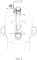
FIG. 2 illustrates a schematic drawing showing corresponding positions of the conventional endotracheal tube placed onto the laryngoscope blade after being inserted into a human trachea. -
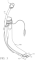
FIG. 3 illustrates a schematic drawing of an endotracheal tube placed onto a laryngoscope blade according to a first embodiment of the present invention. -
FIG. 4A illustrates a schematic drawing of the endotracheal tube according to the first embodiment of the present invention. -
FIG. 4B illustrates a schematic drawing showing a circular projection surface on a vertical plane relative to an oblique cutting surface of the endotracheal tube according to the present disclosure, wherein only angles θ within the range of 15° < θ < 45° are covered by the claim set. -
FIG. 5 illustrates a cross-sectional schematic drawing of a front end of the endotracheal tube according to the first embodiment of the present invention. -
FIG. 6 illustrates a schematic drawing showing corresponding positions of the endotracheal tube placed onto the laryngoscope blade after being inserted into a human trachea according to the present invention. -
FIG. 7 illustrates a right side view of the endotracheal tube according to a second embodiment of the present invention, wherein the second embodiment is not showing all features ofclaim 1, but is provided as additional information. -
FIG. 8 illustrates a left side view of the endotracheal tube according to the second embodiment of the present invention, wherein the second embodiment is not showing all features ofclaim 1, but is provided as additional information. -
FIG. 9 illustrates a top view of the endotracheal tube according to the second embodiment of the present invention, wherein the second embodiment is not showing all features ofclaim 1, but is provided as additional information. -
FIG. 10 illustrates a bottom view of the endotracheal tube according to the second embodiment of the present invention, wherein the second embodiment is not showing all features ofclaim 1, but is provided as additional information. - Please refer to
FIG. 3 to FIG. 6 , whereinFIG. 3 illustrates a schematic drawing of an endotracheal tube placed onto a laryngoscope blade according to a first embodiment of the present invention;FIG. 4A illustrates a schematic drawing of the endotracheal tube according to the first embodiment of the present invention;FIG. 4B illustrates a schematic drawing showing a circular projection surface on a vertical plane relative to an oblique cutting surface of the endotracheal tube according to the present invention;FIG. 5 illustrates a cross-sectional schematic drawing of a front end of the endotracheal tube according to the first embodiment of the present invention; andFIG. 6 illustrates a schematic drawing showing corresponding positions of the endotracheal tube placed onto the laryngoscope blade after being inserted into a human trachea according to the present invention. - As shown in
FIG. 3 ,FIG. 4A and FIG. 4B , in the first embodiment, anendotracheal tube 1 of the present invention comprises acurved tube body 10 and anoblique cutting surface 20. Thecurved tube body 10 has afront end 11. Thecurved tube body 10 has acenter axis 12, aninner axis 13 and anouter axis 14. Theoblique cutting surface 20 has atip 21, and theoblique cutting surface 20 is located at thefront end 11. Theendotracheal tube 1 of the present invention is characterized in that: theoblique cutting surface 20 has acircular projection surface 29 on a vertical plane P, thetip 21 has a tip projection point 21' on the circumference of thecircular projection surface 29, theinner axis 13 has an inner axis projection point 13' on the circumference of thecircular projection surface 29, and the tip projection point 21' and the inner axis projection point 13' form an angle θ, where -45° < θ < 90° , wherein only angles θ within the range of 15° < θ < 45° are covered by the claim set. By means of changing the direction of thetip 21 of theoblique cutting surface 20, as shown inFIG. 6 , thetip 21 of theendotracheal tube 1 of the present invention may face toward the center of a patient'stracheal passage 700 if the width of the patient's larynx is smaller than 4 cm so as to increase the success rate of endotracheal intubation, especially by increasing the success rate of endotracheal intubation on those patients having a smaller oral cavity or narrower larynx, which increase the difficulty of endotracheal intubation, and also to reduce the risk of soft tissue injury caused by thetip 21. Please note that, as shown inFIG. 4B , on thecircular projection surface 29, the inner axis projection point 13' is used as a starting point for defining moving right (i.e., moving along the clockwise direction) from the inner axis projection point 13' as being positive, and moving left (i.e., moving along the counterclockwise direction) from the inner axis projection point 13' as being negative. As a result, -45° means the tip projection point 21' is located to the left of the inner axis projection point 13', which is illustrated as angle θ" inFIG. 4B (provided as additional information; please note that only angles θ within the range of 15° < θ < 45° are covered by the claim set). Similarly, θ < 90° means the tip projection point 21' is located to the right of the inner axis projection point 13', which is illustrated as angle θ' inFIG. 4B (provided as additional information; please note that only angles θ within the range of 15° < θ < 45° are covered by the claim set). Please note that, as shown inFIG. 4A , thetip 21 of theendotracheal tube 1 of the first embodiment would have its tip projection point 21' projected onto the circumference of thecircular projection surface 29 at the angle of θ = 90°; however, please note that the scope of the present invention is limited to 15° < θ < 45°. - Please refer to the
center axis 12, theinner axis 13 and theouter axis 14 of thecurved tube body 10 as shown inFIG. 4A andFIG. 5 , wherein thecenter axis 12 is an extended line of the pipe center of thecurved tube body 10, theinner axis 13 is an axis located at the side of thecurved tube body 10 and has a higher curvature when thecurved tube body 10 bends naturally, and theouter axis 14 is an axis located at the side of thecurved tube body 10 and has a lower curvature when thecurved tube body 10 bends naturally. - As shown in
FIG. 3 ,FIG. 4A ,FIG. 4 ,FIG. 5 andFIG. 6 , thefront end 11 comprises a rightside tube portion 111 and a leftside tube portion 112. According to theendotracheal tube 1 of the present invention, positions of the rightside tube portion 111 and the leftside tube portion 112 are defined based on the viewing angle of the cross-sectional schematic drawing of thefront end 11 as shown inFIG. 5 , wherein the right side of the cross-sectional schematic drawing is the rightside tube portion 111, and the left side of the cross-sectional schematic drawing is the leftside tube portion 112. The cutting direction of theoblique cutting surface 20 of theendotracheal tube 1 of the present invention is oblique from the rightside tube portion 111 to the leftside tube portion 112, which is different from the cutting direction of the conventionalendotracheal tube 800, such that when thetip 21 of theendotracheal tube 1 of the present invention is used with thelaryngoscope blade 900, thetip 21 of theendotracheal tube 1 of the present invention will be located at the center of thetracheal passage 700, as shown inFIG. 6 , so as to increase the success rate of endotracheal intubation, as well as to effectively reduce the risk of soft tissue injury caused by thetip 21. - Please refer to
FIG. 3 ,FIG. 4B andFIG. 5 . Theendotracheal tube 1 of the present invention comprises afirst opening 30 and asecond opening 40. Thefirst opening 30 and thesecond opening 40 are both located on thefront end 11 and are respectively located on two opposite sides of thetip 21. According to the arrangement of thefirst opening 30 and thesecond opening 40, oxygen may enter the patient's lung to maintain the patient's respiration if theoblique cutting surface 20 is blocked. In the first embodiment of the present invention, thefirst opening 30 is located at the rightside tube portion 111 and thesecond opening 40 is located at the leftside tube portion 112, wherein thefirst opening 30 is elliptical in shape and thesecond opening 40 is circular in shape. Thefirst opening 30 has a first aperture 31, thesecond opening 40 has a second aperture 41, and the first aperture 31 is greater than the second aperture 41. According to one preferred embodiment of the present invention, the size of the second aperture 41 is, but is not limited to, 20% to 80% of the size of the first aperture 31. - Please refer to
FIG. 4B andFIGs. 7 to 10 , which present the right side view, left side view, top view and bottom view of the endotracheal tube according to a second embodiment of the present invention, wherein the second embodiment is not showing all features ofclaim 1, but is provided as additional information. - As shown in
FIG. 4B andFIGs. 7 to 10 , the difference between the first embodiment and the second embodiment is that thetip 21 of the endotracheal tube 1a of the second embodiment has its tip projection point 21' projected onto the circumference of thecircular projection surface 29 at the angle of θ = 0°. At this time, thefirst opening 30 and thesecond opening 40 are both located on thefront end 11 and are respectively located on two opposite sides of thetip 21. Thefirst opening 30 is located at the rightside tube portion 111, and thesecond opening 40 is located at the leftside tube portion 112. - The
endotracheal tubes 1 and 1a of the present invention can make thetip 21 face toward the center of the patient'stracheal passage 700 upon movement of thelaryngoscope blade 900 so as to increase the success rate of endotracheal intubation. Because the cutting direction of theoblique cutting surface 20 located at thefront end 11 of theendotracheal tubes 1 and 1a of the present invention is oblique from the rightside tube portion 111 to the leftside tube portion 112, thetip 21 of theendotracheal tubes 1 and 1a can therefore face toward the center of the patient'stracheal passage 700 if the width of the patient's larynx is smaller than 4 cm so as to increase the success rate of endotracheal intubation, especially for those patients having a smaller oral cavity or narrower larynx, which increase the difficulty of endotracheal intubation, and also to reduce the risk of soft tissue injury caused by thetip 21. - Although the present invention has been explained in relation to its preferred embodiments, it is to be understood that many other possible modifications and variations can be made without departing from the scope of the invention as hereinafter claimed.
Claims (7)
- An endotracheal tube (1), comprising a curved tube body (10) and an oblique cutting surface (20), the curved tube body (10) having a front end (11) and the curved tube body (10) having a center axis (12), an inner axis (13) and an outer axis (14), the oblique cutting surface (20) having a tip (21) and the oblique cutting surface (20) being located at the front end (11), wherein the oblique cutting surface (20) has a circular projection surface (29) on a vertical plane (P), the tip (21) has a tip projection point (21') on the circumference of the circular projection surface (29), the inner axis (13) has an inner axis projection point (13') on the circumference of the circular projection surface (29), and wherein the endotracheal tube (1) is characterized in that: the tip projection point (21') and the inner axis projection point (13') form an angle θ, where 15° < θ < 45°; wherein, on the circular projection surface (29), the inner axis projection point (13') is used as a starting point for defining moving along the clockwise direction from the inner axis projection point (13') as being positive, and moving along the counterclockwise direction from the inner axis projection point (13') as being negative.
- The endotracheal tube (1) as claimed in claim 1, further comprising a first opening (30) and a second opening (40), wherein the first opening (30) and the second opening (40) are both located on the front end (11) and respectively located on two opposite sides of the tip (21).
- The endotracheal tube (1) as claimed in claim 2, wherein the front end (11) further comprises a right side tube portion (111) and a left side tube portion (112), the first opening (30) being located on the right side tube portion (111) and the second opening (40) being located on the left side tube portion (112).
- The endotracheal tube (1) as claimed in claim 1, wherein the endotracheal tube (1) comprises a first opening (30) and a second opening (40), and the front end (11) comprises a right side tube portion and a left side tube portion, the first opening and the tip being located on the right side tube portion and the second opening being located on the left side tube portion.
- The endotracheal tube (1) as claimed in any of claims 2 to 4, wherein the first opening (30) has a first aperture (31), the second opening (40) has a second aperture (41), and the first aperture (31) is greater in size than the second aperture (41).
- The endotracheal tube (1) as claimed in claim 5, wherein the size of the second aperture (41) is 20% to 80% of the size of the first aperture (31).
- The endotracheal tube (1) as claimed in claim 6, wherein the first opening (30) is elliptical in shape and the second opening (40) is circular in shape.
Applications Claiming Priority (1)
| Application Number | Priority Date | Filing Date | Title |
|---|---|---|---|
| TW109144561 | 2020-12-16 |
Publications (3)
| Publication Number | Publication Date |
|---|---|
| EP4015024A1 EP4015024A1 (en) | 2022-06-22 |
| EP4015024B1 true EP4015024B1 (en) | 2024-03-13 |
| EP4015024C0 EP4015024C0 (en) | 2024-03-13 |
Family
ID=78825027
Family Applications (1)
| Application Number | Title | Priority Date | Filing Date |
|---|---|---|---|
| EP21213107.2A Active EP4015024B1 (en) | 2020-12-16 | 2021-12-08 | Endotracheal tube |
Country Status (3)
| Country | Link |
|---|---|
| US (1) | US20220184334A1 (en) |
| EP (1) | EP4015024B1 (en) |
| TW (1) | TWI799003B (en) |
Families Citing this family (1)
| Publication number | Priority date | Publication date | Assignee | Title |
|---|---|---|---|---|
| US12672769B2 (en) * | 2022-09-07 | 2026-07-07 | Anthony Alatriste | Endotracheal intubation device and related methods |
Family Cites Families (13)
| Publication number | Priority date | Publication date | Assignee | Title |
|---|---|---|---|---|
| US5540224A (en) * | 1993-07-01 | 1996-07-30 | Mallinckrodt Medical, Inc. | Drug Delivery port endotracheal tube |
| GB2377386B (en) * | 2001-06-22 | 2004-09-08 | Smiths Group Plc | Bendable endotracheal tubes |
| US20030226566A1 (en) * | 2002-06-06 | 2003-12-11 | Dhuper Sunil Kumar | Endotracheal tube with aerosol delivery apparatus II |
| US20080047562A1 (en) * | 2004-05-12 | 2008-02-28 | Nellcor Puritan Bennett Incorporated | Endotracheal Tube Having Improved Suction Lumen |
| US8603049B2 (en) * | 2008-12-15 | 2013-12-10 | Kimberly-Clark Worldwide, Inc. | Atraumatic suction catheter |
| WO2013063520A1 (en) * | 2011-10-27 | 2013-05-02 | Endoclear, Llc | Endotracheal tube coupling adapters |
| WO2015039164A1 (en) * | 2013-09-23 | 2015-03-26 | Dhara Sasanka Sekhar | Endotracheal tube and method of use |
| US9446213B2 (en) * | 2013-10-10 | 2016-09-20 | NevAp, Inc. | Tracheal tube |
| ES2848321T3 (en) * | 2014-09-17 | 2021-08-06 | Richard M Levitan | Intubation Channelizer with Tracheal Tube |
| US10478054B2 (en) * | 2016-02-12 | 2019-11-19 | Ambu A/S | Endotracheal tube with visualization capabilities and a laryngeal mask |
| CN206138541U (en) * | 2016-07-16 | 2017-05-03 | 浙江优亿医疗器械有限公司 | A trachea cannula for glidescope |
| CN209347853U (en) * | 2018-05-30 | 2019-09-06 | 江苏瑞京科技发展有限公司 | One kind can position trachea cannula |
| CN210813271U (en) * | 2019-06-17 | 2020-06-23 | 江苏乐腾医疗器械科技有限公司 | Ultra-smooth antibacterial trachea cannula |
-
2021
- 2021-12-02 US US17/540,382 patent/US20220184334A1/en not_active Abandoned
- 2021-12-08 EP EP21213107.2A patent/EP4015024B1/en active Active
- 2021-12-15 TW TW110147018A patent/TWI799003B/en active
Also Published As
| Publication number | Publication date |
|---|---|
| TWI799003B (en) | 2023-04-11 |
| TW202224715A (en) | 2022-07-01 |
| EP4015024C0 (en) | 2024-03-13 |
| US20220184334A1 (en) | 2022-06-16 |
| EP4015024A1 (en) | 2022-06-22 |
Similar Documents
| Publication | Publication Date | Title |
|---|---|---|
| JP4620811B2 (en) | Endotracheal tube structure | |
| US8573218B2 (en) | Tracheostomy tube | |
| US11179531B2 (en) | Apparatus, systems, and methods for accessing the airway with medical instruments without interruption of assisted respiration | |
| US7128071B2 (en) | Intubating laryngeal mask airway device with fiber optic assembly | |
| US5222487A (en) | Hinged tracheostomy tube obturator | |
| RU2336909C2 (en) | Respiratory device of laryngeal mask | |
| US9427543B2 (en) | Intubation device and method | |
| US4050466A (en) | Endotracheal tube | |
| US20150173598A1 (en) | Intubating Airway | |
| CN101541288A (en) | Baby Nasal Interface Mask | |
| JP2020072930A (en) | Introducer for endotracheal tube intubation | |
| KR101931309B1 (en) | fixing device for endotracheal tube | |
| EP4015024A1 (en) | Endotracheal tube | |
| CN208823699U (en) | A kind of guiding core and sputum-suction trachea cannula applied to endotracheal intubation | |
| WO2021083357A1 (en) | Tracheal catheter | |
| US8425409B2 (en) | Laryngoscope | |
| US20200405990A1 (en) | Medical device system and method including an endotracheal tube | |
| US11975147B2 (en) | Curved bougie guide | |
| TWM611704U (en) | Endotracheal tube | |
| US10426908B1 (en) | Insertion guide for endotracheal tube | |
| CN212326356U (en) | Dysmorphism stereoplasm bronchoscope | |
| KR102607488B1 (en) | Endotracheal tool | |
| CN112546378A (en) | Intubation plasticity method of fitting laryngoscope | |
| CN223026039U (en) | A nasal suction auxiliary mirror | |
| US20240285890A1 (en) | Nasopharyngeal airway device |
Legal Events
| Date | Code | Title | Description |
|---|---|---|---|
| PUAI | Public reference made under article 153(3) epc to a published international application that has entered the european phase |
Free format text: ORIGINAL CODE: 0009012 |
|
| STAA | Information on the status of an ep patent application or granted ep patent |
Free format text: STATUS: THE APPLICATION HAS BEEN PUBLISHED |
|
| AK | Designated contracting states |
Kind code of ref document: A1 Designated state(s): AL AT BE BG CH CY CZ DE DK EE ES FI FR GB GR HR HU IE IS IT LI LT LU LV MC MK MT NL NO PL PT RO RS SE SI SK SM TR |
|
| STAA | Information on the status of an ep patent application or granted ep patent |
Free format text: STATUS: REQUEST FOR EXAMINATION WAS MADE |
|
| 17P | Request for examination filed |
Effective date: 20221221 |
|
| RBV | Designated contracting states (corrected) |
Designated state(s): AL AT BE BG CH CY CZ DE DK EE ES FI FR GB GR HR HU IE IS IT LI LT LU LV MC MK MT NL NO PL PT RO RS SE SI SK SM TR |
|
| GRAP | Despatch of communication of intention to grant a patent |
Free format text: ORIGINAL CODE: EPIDOSNIGR1 |
|
| STAA | Information on the status of an ep patent application or granted ep patent |
Free format text: STATUS: GRANT OF PATENT IS INTENDED |
|
| INTG | Intention to grant announced |
Effective date: 20231027 |
|
| GRAS | Grant fee paid |
Free format text: ORIGINAL CODE: EPIDOSNIGR3 |
|
| GRAA | (expected) grant |
Free format text: ORIGINAL CODE: 0009210 |
|
| STAA | Information on the status of an ep patent application or granted ep patent |
Free format text: STATUS: THE PATENT HAS BEEN GRANTED |
|
| AK | Designated contracting states |
Kind code of ref document: B1 Designated state(s): AL AT BE BG CH CY CZ DE DK EE ES FI FR GB GR HR HU IE IS IT LI LT LU LV MC MK MT NL NO PL PT RO RS SE SI SK SM TR |
|
| REG | Reference to a national code |
Ref country code: GB Ref legal event code: FG4D |
|
| REG | Reference to a national code |
Ref country code: CH Ref legal event code: EP |
|
| REG | Reference to a national code |
Ref country code: DE Ref legal event code: R096 Ref document number: 602021010364 Country of ref document: DE |
|
| REG | Reference to a national code |
Ref country code: IE Ref legal event code: FG4D |
|
| U01 | Request for unitary effect filed |
Effective date: 20240314 |
|
| U07 | Unitary effect registered |
Designated state(s): AT BE BG DE DK EE FI FR IT LT LU LV MT NL PT SE SI Effective date: 20240325 |
|
| PG25 | Lapsed in a contracting state [announced via postgrant information from national office to epo] |
Ref country code: GR Free format text: LAPSE BECAUSE OF FAILURE TO SUBMIT A TRANSLATION OF THE DESCRIPTION OR TO PAY THE FEE WITHIN THE PRESCRIBED TIME-LIMIT Effective date: 20240614 |
|
| PG25 | Lapsed in a contracting state [announced via postgrant information from national office to epo] |
Ref country code: RS Free format text: LAPSE BECAUSE OF FAILURE TO SUBMIT A TRANSLATION OF THE DESCRIPTION OR TO PAY THE FEE WITHIN THE PRESCRIBED TIME-LIMIT Effective date: 20240613 Ref country code: HR Free format text: LAPSE BECAUSE OF FAILURE TO SUBMIT A TRANSLATION OF THE DESCRIPTION OR TO PAY THE FEE WITHIN THE PRESCRIBED TIME-LIMIT Effective date: 20240313 |
|
| PG25 | Lapsed in a contracting state [announced via postgrant information from national office to epo] |
Ref country code: ES Free format text: LAPSE BECAUSE OF FAILURE TO SUBMIT A TRANSLATION OF THE DESCRIPTION OR TO PAY THE FEE WITHIN THE PRESCRIBED TIME-LIMIT Effective date: 20240313 |
|
| PG25 | Lapsed in a contracting state [announced via postgrant information from national office to epo] |
Ref country code: RS Free format text: LAPSE BECAUSE OF FAILURE TO SUBMIT A TRANSLATION OF THE DESCRIPTION OR TO PAY THE FEE WITHIN THE PRESCRIBED TIME-LIMIT Effective date: 20240613 Ref country code: NO Free format text: LAPSE BECAUSE OF FAILURE TO SUBMIT A TRANSLATION OF THE DESCRIPTION OR TO PAY THE FEE WITHIN THE PRESCRIBED TIME-LIMIT Effective date: 20240613 Ref country code: HR Free format text: LAPSE BECAUSE OF FAILURE TO SUBMIT A TRANSLATION OF THE DESCRIPTION OR TO PAY THE FEE WITHIN THE PRESCRIBED TIME-LIMIT Effective date: 20240313 Ref country code: GR Free format text: LAPSE BECAUSE OF FAILURE TO SUBMIT A TRANSLATION OF THE DESCRIPTION OR TO PAY THE FEE WITHIN THE PRESCRIBED TIME-LIMIT Effective date: 20240614 Ref country code: ES Free format text: LAPSE BECAUSE OF FAILURE TO SUBMIT A TRANSLATION OF THE DESCRIPTION OR TO PAY THE FEE WITHIN THE PRESCRIBED TIME-LIMIT Effective date: 20240313 |
|
| PG25 | Lapsed in a contracting state [announced via postgrant information from national office to epo] |
Ref country code: IS Free format text: LAPSE BECAUSE OF FAILURE TO SUBMIT A TRANSLATION OF THE DESCRIPTION OR TO PAY THE FEE WITHIN THE PRESCRIBED TIME-LIMIT Effective date: 20240713 |
|
| PG25 | Lapsed in a contracting state [announced via postgrant information from national office to epo] |
Ref country code: SM Free format text: LAPSE BECAUSE OF FAILURE TO SUBMIT A TRANSLATION OF THE DESCRIPTION OR TO PAY THE FEE WITHIN THE PRESCRIBED TIME-LIMIT Effective date: 20240313 |
|
| PG25 | Lapsed in a contracting state [announced via postgrant information from national office to epo] |
Ref country code: CZ Free format text: LAPSE BECAUSE OF FAILURE TO SUBMIT A TRANSLATION OF THE DESCRIPTION OR TO PAY THE FEE WITHIN THE PRESCRIBED TIME-LIMIT Effective date: 20240313 |
|
| PG25 | Lapsed in a contracting state [announced via postgrant information from national office to epo] |
Ref country code: PL Free format text: LAPSE BECAUSE OF FAILURE TO SUBMIT A TRANSLATION OF THE DESCRIPTION OR TO PAY THE FEE WITHIN THE PRESCRIBED TIME-LIMIT Effective date: 20240313 |
|
| PG25 | Lapsed in a contracting state [announced via postgrant information from national office to epo] |
Ref country code: SK Free format text: LAPSE BECAUSE OF FAILURE TO SUBMIT A TRANSLATION OF THE DESCRIPTION OR TO PAY THE FEE WITHIN THE PRESCRIBED TIME-LIMIT Effective date: 20240313 |
|
| PG25 | Lapsed in a contracting state [announced via postgrant information from national office to epo] |
Ref country code: SM Free format text: LAPSE BECAUSE OF FAILURE TO SUBMIT A TRANSLATION OF THE DESCRIPTION OR TO PAY THE FEE WITHIN THE PRESCRIBED TIME-LIMIT Effective date: 20240313 Ref country code: SK Free format text: LAPSE BECAUSE OF FAILURE TO SUBMIT A TRANSLATION OF THE DESCRIPTION OR TO PAY THE FEE WITHIN THE PRESCRIBED TIME-LIMIT Effective date: 20240313 Ref country code: RO Free format text: LAPSE BECAUSE OF FAILURE TO SUBMIT A TRANSLATION OF THE DESCRIPTION OR TO PAY THE FEE WITHIN THE PRESCRIBED TIME-LIMIT Effective date: 20240313 Ref country code: PL Free format text: LAPSE BECAUSE OF FAILURE TO SUBMIT A TRANSLATION OF THE DESCRIPTION OR TO PAY THE FEE WITHIN THE PRESCRIBED TIME-LIMIT Effective date: 20240313 Ref country code: IS Free format text: LAPSE BECAUSE OF FAILURE TO SUBMIT A TRANSLATION OF THE DESCRIPTION OR TO PAY THE FEE WITHIN THE PRESCRIBED TIME-LIMIT Effective date: 20240713 Ref country code: CZ Free format text: LAPSE BECAUSE OF FAILURE TO SUBMIT A TRANSLATION OF THE DESCRIPTION OR TO PAY THE FEE WITHIN THE PRESCRIBED TIME-LIMIT Effective date: 20240313 |
|
| REG | Reference to a national code |
Ref country code: DE Ref legal event code: R097 Ref document number: 602021010364 Country of ref document: DE |
|
| U20 | Renewal fee for the european patent with unitary effect paid |
Year of fee payment: 4 Effective date: 20241211 |
|
| PLBE | No opposition filed within time limit |
Free format text: ORIGINAL CODE: 0009261 |
|
| STAA | Information on the status of an ep patent application or granted ep patent |
Free format text: STATUS: NO OPPOSITION FILED WITHIN TIME LIMIT |
|
| 26N | No opposition filed |
Effective date: 20241216 |
|
| PG25 | Lapsed in a contracting state [announced via postgrant information from national office to epo] |
Ref country code: MC Free format text: LAPSE BECAUSE OF FAILURE TO SUBMIT A TRANSLATION OF THE DESCRIPTION OR TO PAY THE FEE WITHIN THE PRESCRIBED TIME-LIMIT Effective date: 20240313 |
|
| REG | Reference to a national code |
Ref country code: CH Ref legal event code: PL |
|
| PG25 | Lapsed in a contracting state [announced via postgrant information from national office to epo] |
Ref country code: CH Free format text: LAPSE BECAUSE OF NON-PAYMENT OF DUE FEES Effective date: 20241231 |
|
| PG25 | Lapsed in a contracting state [announced via postgrant information from national office to epo] |
Ref country code: IE Free format text: LAPSE BECAUSE OF NON-PAYMENT OF DUE FEES Effective date: 20241208 |
|
| PG25 | Lapsed in a contracting state [announced via postgrant information from national office to epo] |
Ref country code: CY Free format text: LAPSE BECAUSE OF FAILURE TO SUBMIT A TRANSLATION OF THE DESCRIPTION OR TO PAY THE FEE WITHIN THE PRESCRIBED TIME-LIMIT Effective date: 20240313 |
|
| PG25 | Lapsed in a contracting state [announced via postgrant information from national office to epo] |
Ref country code: TR Free format text: LAPSE BECAUSE OF FAILURE TO SUBMIT A TRANSLATION OF THE DESCRIPTION OR TO PAY THE FEE WITHIN THE PRESCRIBED TIME-LIMIT Effective date: 20240313 |
|
| PG25 | Lapsed in a contracting state [announced via postgrant information from national office to epo] |
Ref country code: HU Free format text: LAPSE BECAUSE OF FAILURE TO SUBMIT A TRANSLATION OF THE DESCRIPTION OR TO PAY THE FEE WITHIN THE PRESCRIBED TIME-LIMIT; INVALID AB INITIO Effective date: 20211208 |