EP4014942A1 - Electric walking assisting vehicle - Google Patents
Electric walking assisting vehicle Download PDFInfo
- Publication number
- EP4014942A1 EP4014942A1 EP21212921.7A EP21212921A EP4014942A1 EP 4014942 A1 EP4014942 A1 EP 4014942A1 EP 21212921 A EP21212921 A EP 21212921A EP 4014942 A1 EP4014942 A1 EP 4014942A1
- Authority
- EP
- European Patent Office
- Prior art keywords
- torque
- rotation speed
- driving wheels
- control unit
- motors
- Prior art date
- Legal status (The legal status is an assumption and is not a legal conclusion. Google has not performed a legal analysis and makes no representation as to the accuracy of the status listed.)
- Granted
Links
Images



Classifications
-
- A—HUMAN NECESSITIES
- A61—MEDICAL OR VETERINARY SCIENCE; HYGIENE
- A61H—PHYSICAL THERAPY APPARATUS, e.g. DEVICES FOR LOCATING OR STIMULATING REFLEX POINTS IN THE BODY; ARTIFICIAL RESPIRATION; MASSAGE; BATHING DEVICES FOR SPECIAL THERAPEUTIC OR HYGIENIC PURPOSES OR SPECIFIC PARTS OF THE BODY
- A61H3/00—Appliances for aiding patients or disabled persons to walk about
- A61H3/04—Wheeled walking aids for patients or disabled persons
-
- A—HUMAN NECESSITIES
- A61—MEDICAL OR VETERINARY SCIENCE; HYGIENE
- A61G—TRANSPORT, PERSONAL CONVEYANCES, OR ACCOMMODATION SPECIALLY ADAPTED FOR PATIENTS OR DISABLED PERSONS; OPERATING TABLES OR CHAIRS; CHAIRS FOR DENTISTRY; FUNERAL DEVICES
- A61G5/00—Chairs or personal conveyances specially adapted for patients or disabled persons, e.g. wheelchairs
- A61G5/04—Chairs or personal conveyances specially adapted for patients or disabled persons, e.g. wheelchairs motor-driven
-
- A—HUMAN NECESSITIES
- A61—MEDICAL OR VETERINARY SCIENCE; HYGIENE
- A61G—TRANSPORT, PERSONAL CONVEYANCES, OR ACCOMMODATION SPECIALLY ADAPTED FOR PATIENTS OR DISABLED PERSONS; OPERATING TABLES OR CHAIRS; CHAIRS FOR DENTISTRY; FUNERAL DEVICES
- A61G2203/00—General characteristics of devices
- A61G2203/10—General characteristics of devices characterised by specific control means, e.g. for adjustment or steering
- A61G2203/14—Joysticks
-
- A—HUMAN NECESSITIES
- A61—MEDICAL OR VETERINARY SCIENCE; HYGIENE
- A61H—PHYSICAL THERAPY APPARATUS, e.g. DEVICES FOR LOCATING OR STIMULATING REFLEX POINTS IN THE BODY; ARTIFICIAL RESPIRATION; MASSAGE; BATHING DEVICES FOR SPECIAL THERAPEUTIC OR HYGIENIC PURPOSES OR SPECIFIC PARTS OF THE BODY
- A61H3/00—Appliances for aiding patients or disabled persons to walk about
- A61H3/04—Wheeled walking aids for patients or disabled persons
- A61H2003/043—Wheeled walking aids for patients or disabled persons with a drive mechanism
-
- A—HUMAN NECESSITIES
- A61—MEDICAL OR VETERINARY SCIENCE; HYGIENE
- A61H—PHYSICAL THERAPY APPARATUS, e.g. DEVICES FOR LOCATING OR STIMULATING REFLEX POINTS IN THE BODY; ARTIFICIAL RESPIRATION; MASSAGE; BATHING DEVICES FOR SPECIAL THERAPEUTIC OR HYGIENIC PURPOSES OR SPECIFIC PARTS OF THE BODY
- A61H3/00—Appliances for aiding patients or disabled persons to walk about
- A61H3/04—Wheeled walking aids for patients or disabled persons
- A61H2003/046—Wheeled walking aids for patients or disabled persons with braking means
-
- A—HUMAN NECESSITIES
- A61—MEDICAL OR VETERINARY SCIENCE; HYGIENE
- A61H—PHYSICAL THERAPY APPARATUS, e.g. DEVICES FOR LOCATING OR STIMULATING REFLEX POINTS IN THE BODY; ARTIFICIAL RESPIRATION; MASSAGE; BATHING DEVICES FOR SPECIAL THERAPEUTIC OR HYGIENIC PURPOSES OR SPECIFIC PARTS OF THE BODY
- A61H2201/00—Characteristics of apparatus not provided for in the preceding codes
- A61H2201/01—Constructive details
- A61H2201/0161—Size reducing arrangements when not in use, for stowing or transport
-
- A—HUMAN NECESSITIES
- A61—MEDICAL OR VETERINARY SCIENCE; HYGIENE
- A61H—PHYSICAL THERAPY APPARATUS, e.g. DEVICES FOR LOCATING OR STIMULATING REFLEX POINTS IN THE BODY; ARTIFICIAL RESPIRATION; MASSAGE; BATHING DEVICES FOR SPECIAL THERAPEUTIC OR HYGIENIC PURPOSES OR SPECIFIC PARTS OF THE BODY
- A61H2201/00—Characteristics of apparatus not provided for in the preceding codes
- A61H2201/01—Constructive details
- A61H2201/0173—Means for preventing injuries
- A61H2201/018—By limiting the applied torque or force
-
- A—HUMAN NECESSITIES
- A61—MEDICAL OR VETERINARY SCIENCE; HYGIENE
- A61H—PHYSICAL THERAPY APPARATUS, e.g. DEVICES FOR LOCATING OR STIMULATING REFLEX POINTS IN THE BODY; ARTIFICIAL RESPIRATION; MASSAGE; BATHING DEVICES FOR SPECIAL THERAPEUTIC OR HYGIENIC PURPOSES OR SPECIFIC PARTS OF THE BODY
- A61H2201/00—Characteristics of apparatus not provided for in the preceding codes
- A61H2201/12—Driving means
- A61H2201/1207—Driving means with electric or magnetic drive
-
- A—HUMAN NECESSITIES
- A61—MEDICAL OR VETERINARY SCIENCE; HYGIENE
- A61H—PHYSICAL THERAPY APPARATUS, e.g. DEVICES FOR LOCATING OR STIMULATING REFLEX POINTS IN THE BODY; ARTIFICIAL RESPIRATION; MASSAGE; BATHING DEVICES FOR SPECIAL THERAPEUTIC OR HYGIENIC PURPOSES OR SPECIFIC PARTS OF THE BODY
- A61H2201/00—Characteristics of apparatus not provided for in the preceding codes
- A61H2201/16—Physical interface with patient
- A61H2201/1602—Physical interface with patient kind of interface, e.g. head rest, knee support or lumbar support
- A61H2201/1628—Pelvis
- A61H2201/1633—Seat
-
- A—HUMAN NECESSITIES
- A61—MEDICAL OR VETERINARY SCIENCE; HYGIENE
- A61H—PHYSICAL THERAPY APPARATUS, e.g. DEVICES FOR LOCATING OR STIMULATING REFLEX POINTS IN THE BODY; ARTIFICIAL RESPIRATION; MASSAGE; BATHING DEVICES FOR SPECIAL THERAPEUTIC OR HYGIENIC PURPOSES OR SPECIFIC PARTS OF THE BODY
- A61H2201/00—Characteristics of apparatus not provided for in the preceding codes
- A61H2201/16—Physical interface with patient
- A61H2201/1602—Physical interface with patient kind of interface, e.g. head rest, knee support or lumbar support
- A61H2201/1635—Hand or arm, e.g. handle
-
- A—HUMAN NECESSITIES
- A61—MEDICAL OR VETERINARY SCIENCE; HYGIENE
- A61H—PHYSICAL THERAPY APPARATUS, e.g. DEVICES FOR LOCATING OR STIMULATING REFLEX POINTS IN THE BODY; ARTIFICIAL RESPIRATION; MASSAGE; BATHING DEVICES FOR SPECIAL THERAPEUTIC OR HYGIENIC PURPOSES OR SPECIFIC PARTS OF THE BODY
- A61H2201/00—Characteristics of apparatus not provided for in the preceding codes
- A61H2201/50—Control means thereof
- A61H2201/5023—Interfaces to the user
- A61H2201/5025—Activation means
-
- A—HUMAN NECESSITIES
- A61—MEDICAL OR VETERINARY SCIENCE; HYGIENE
- A61H—PHYSICAL THERAPY APPARATUS, e.g. DEVICES FOR LOCATING OR STIMULATING REFLEX POINTS IN THE BODY; ARTIFICIAL RESPIRATION; MASSAGE; BATHING DEVICES FOR SPECIAL THERAPEUTIC OR HYGIENIC PURPOSES OR SPECIFIC PARTS OF THE BODY
- A61H2201/00—Characteristics of apparatus not provided for in the preceding codes
- A61H2201/50—Control means thereof
- A61H2201/5023—Interfaces to the user
- A61H2201/5043—Displays
-
- A—HUMAN NECESSITIES
- A61—MEDICAL OR VETERINARY SCIENCE; HYGIENE
- A61H—PHYSICAL THERAPY APPARATUS, e.g. DEVICES FOR LOCATING OR STIMULATING REFLEX POINTS IN THE BODY; ARTIFICIAL RESPIRATION; MASSAGE; BATHING DEVICES FOR SPECIAL THERAPEUTIC OR HYGIENIC PURPOSES OR SPECIFIC PARTS OF THE BODY
- A61H2201/00—Characteristics of apparatus not provided for in the preceding codes
- A61H2201/50—Control means thereof
- A61H2201/5058—Sensors or detectors
-
- A—HUMAN NECESSITIES
- A61—MEDICAL OR VETERINARY SCIENCE; HYGIENE
- A61H—PHYSICAL THERAPY APPARATUS, e.g. DEVICES FOR LOCATING OR STIMULATING REFLEX POINTS IN THE BODY; ARTIFICIAL RESPIRATION; MASSAGE; BATHING DEVICES FOR SPECIAL THERAPEUTIC OR HYGIENIC PURPOSES OR SPECIFIC PARTS OF THE BODY
- A61H2201/00—Characteristics of apparatus not provided for in the preceding codes
- A61H2201/50—Control means thereof
- A61H2201/5058—Sensors or detectors
- A61H2201/5061—Force sensors
-
- A—HUMAN NECESSITIES
- A61—MEDICAL OR VETERINARY SCIENCE; HYGIENE
- A61H—PHYSICAL THERAPY APPARATUS, e.g. DEVICES FOR LOCATING OR STIMULATING REFLEX POINTS IN THE BODY; ARTIFICIAL RESPIRATION; MASSAGE; BATHING DEVICES FOR SPECIAL THERAPEUTIC OR HYGIENIC PURPOSES OR SPECIFIC PARTS OF THE BODY
- A61H2201/00—Characteristics of apparatus not provided for in the preceding codes
- A61H2201/50—Control means thereof
- A61H2201/5058—Sensors or detectors
- A61H2201/5069—Angle sensors
-
- A—HUMAN NECESSITIES
- A61—MEDICAL OR VETERINARY SCIENCE; HYGIENE
- A61H—PHYSICAL THERAPY APPARATUS, e.g. DEVICES FOR LOCATING OR STIMULATING REFLEX POINTS IN THE BODY; ARTIFICIAL RESPIRATION; MASSAGE; BATHING DEVICES FOR SPECIAL THERAPEUTIC OR HYGIENIC PURPOSES OR SPECIFIC PARTS OF THE BODY
- A61H2201/00—Characteristics of apparatus not provided for in the preceding codes
- A61H2201/50—Control means thereof
- A61H2201/5058—Sensors or detectors
- A61H2201/5079—Velocity sensors
-
- Y—GENERAL TAGGING OF NEW TECHNOLOGICAL DEVELOPMENTS; GENERAL TAGGING OF CROSS-SECTIONAL TECHNOLOGIES SPANNING OVER SEVERAL SECTIONS OF THE IPC; TECHNICAL SUBJECTS COVERED BY FORMER USPC CROSS-REFERENCE ART COLLECTIONS [XRACs] AND DIGESTS
- Y02—TECHNOLOGIES OR APPLICATIONS FOR MITIGATION OR ADAPTATION AGAINST CLIMATE CHANGE
- Y02T—CLIMATE CHANGE MITIGATION TECHNOLOGIES RELATED TO TRANSPORTATION
- Y02T10/00—Road transport of goods or passengers
- Y02T10/60—Other road transportation technologies with climate change mitigation effect
- Y02T10/72—Electric energy management in electromobility
Definitions
- the present invention relates to an electric walking assisting vehicle.
- Patent Literature 1 discloses a push cart in which driving torque of an electric motor is controlled such that a force pushing handlebars by a user is detected by a force sensor and an assist force is imparted in accordance with a magnitude and a direction of the detected force.
- Patent Literature 1 JP 6620326 B2
- this apparatus has a configuration in which a pressure (handle force) exerted on the handlebars by a user is detected by the force sensor (pressure sensor) attached in a part joining the handlebars and a supporting post and the assist force is determined, there has arisen a problem in that control and structure thereof are complicated.
- An object of the present invention is to provide an electric walking assisting vehicle which is operable to provide a stable assist by a simple configuration in accordance with circumstances.
- an electric walking assisting vehicle includes: a vehicle body having a forward-backward direction and a width direction; left and right driving wheels provided spaced apart in the width direction of the vehicle body; left and right motors which are connected so as to respectively transmit power to the left and right driving wheels; universal wheels provided spaced apart from the left and right driving wheels in the forward-backward direction of the vehicle body; a gripping part provided in an upper portion of the vehicle body so as to be gripped by a user in a standing and walking posture; a gripping sensor for detecting that the gripping part is gripped by the user; left and right rotation speed sensors for individually detecting rotation speeds of the left and right driving wheels; and a control unit for controlling the left and right motors, wherein the control unit is configured to generate torque in the left and right motors in accordance with a torque map which defines relationships of the rotation speeds of the left and right driving wheels detected by the left and right rotation speed sensors and torque command values of the left and right motors in a state
- the electric walking assisting vehicle is configured, as described above, to generate torque in the left and right motors in accordance with the rotation speeds of the left and right driving wheels, detected in conjunction with operations of pushing/pulling the vehicle body with the gripping parts gripped by a user, a force sensor (pressure sensor) which detects a force of pushing/pulling the gripping parts by the user is unnecessary, and thus, a vehicle body structure and control are simplified.
- a tractive force detected by the force sensor by driving the left and right motors, thus leading to advantages in that a stable assist can be performed by simple operations.
- an electric vehicle 1 includes a vehicle body 2, which is constituted of a moving base 21 (lower traveling body) and an upper frame 22 which is installed in a standing manner in the rear of the moving base 21 (a rear side base 24), and can be utilized in a walking assisting vehicle mode (1) indicated by a solid line in Figure 1 and a compact electric vehicle mode (riding mode 1') indicated by a two-dot chain line in Figure 1 .
- the moving base 21 includes the rear side base 24 (main body part) which is provided with left and right driving wheels 4 (rear wheels) and the upper frame 22 and a front side base 25 which is provided with left and right driven wheels 5 (front wheels), the front side base 25 is coupled to a front side of the rear side base 24 in a manner slidable in a front-rear direction, and a wheel base of the moving base 21 is configured in such a way as to be extendable and contractible.
- the left and right driving wheels 4 are independently driven by left and right motor units 40 (40L and 40R) which are mounted on the rear side base 24.
- the left and right driven wheels 5 are constituted of universal wheels (omni-wheels or omnidirectional wheels), each of which includes, in a treading portion thereof, multiple rollers 50 which can rotate around an axis in a circumferential direction.
- the electric vehicle 1, as described later, can be steered, driven, and braked only by controlling the left and right motor units 40L and 40R.
- the upper frame 22 is of an inverse U-shape or a gate shape in which upper ends of a pair of left and right side part frames installed in a standing manner upward from both left and right side parts of the rear side base 24 are joined by an upper end frame extending in a vehicle width direction, a lower end portion of a stem 31 of a rear handle 3 is rigidly coupled to a joining part 23 in a central portion of the upper end frame in the vehicle width direction, and a seat back 6 is supported on the joining part 23.
- the rear handle 3 is of a T-bar shape and has a pair of left and right gripping parts which extend from a connecting part 32 with the upper end of the stem 31.
- the left and right gripping parts of the rear handle 3 are provided with a gripping sensor 30 which detects a state in which a user (or a helper) grips the gripping parts (hands-on).
- a gripping sensor 30 As the gripping sensor 30, a touch sensor such as a capacitance sensor and a pressure sensor can be used.
- the left and right gripping parts of the rear handle 3 serve as an operation part.
- a base part of a support frame 81 of an armrest 8 is fixed.
- a front end part of the armrest 8 on a right side, which is a depth side in Figure 1 is provided with a riding mode operation unit 83, and a front end part of the armrest 8 on a left side, which is a front side in Figure 1 , is provided with a display unit 80 on an upper surface of the gripping parts (83) having the same shapes.
- the riding mode operation unit 83 is configured by a biaxial joystick, which is tiltable in a front-rear direction and a left-right direction, or the like.
- a support frame 71 of the seat 7 is pivotably supported to a pivotal supporting part 27, which protrudes forward from the bending portion of the upper frame 22 (side part frame), by a shaft 7a in the vehicle width direction, a lower end of the support frame 71 is coupled to the front side base 25 (pin) via a coupling part 7b (slot) in a pivotable and slidable manner.
- the front side base 25 slides backward, the moving base 21 is shortened, and the walking assisting vehicle mode (1) in which the user can grip and operate the rear handle 3 while standing and walking is set.
- FIG. 2 is a block diagram showing a control system of the electric vehicle 1.
- the electric vehicle 1 includes a battery 9 which supplies electric power to the left and right motor units 40 (40L and 40R) and a control unit 10 for controlling the left and right motor units 40 (40L and 40R), and the control unit 10 includes an interlock mechanism which implements control corresponding to the walking assisting vehicle mode (1) and control corresponding to the riding mode (1').
- the riding mode operation unit 83 is disabled, and based on detection information detected by an inclination sensor 20, left and right speed sensors 43, and the like and a previously set control map, the control unit 10 executes control of the left and right motor units 40 (40L and 40R).
- the gripping sensor 30 detects only gripping (hands-on/hands-off) of the rear handle 3 by the user and is not involved in torque control of the motor units 40.
- the gripping sensor 30 is disabled, and based on an operation of the riding mode operation unit 83 and detection information detected by the inclination sensor 20, the control unit 10 executes control of the left and right motor units 40 (40L and 40R).
- the control unit 10 is constituted of: a computer (microcomputer) which includes ROM having stored therein programs and data for executing the control in the abovementioned modes, RAM which temporarily stores an arithmetic processing result, a CPU which performs arithmetic processing, and the like; a driving circuit (motor driver) for left and right motors 41; a power supply circuit including a relay which turns on/off the electric power of the battery 9; and the like.
- Each of the left and right motor units 40 includes a motor 41, an electromagnetic brake 42 for locking a rotor of the motor 41, and a rotation position sensor (43) for detecting a rotation position of the motor 41, and a driving shaft of the motor 41 is connected to each of driving wheels 4 (4L and 4R) via a deceleration gear, not shown, so as to be operable to transmit power thereto.
- each of the left and right motors 41 is constituted of a brushless DC motor which switches a current of each phase coil by a driving circuit so as to match each phase of the rotor, which is detected by the rotation position sensor (43), and as described later, in the walking assisting vehicle mode (1), a rotation position sensor (Hall sensor) is used as a rotation speed sensor 43.
- a rotation position sensor Hall sensor
- each of the left and right motors 41 includes a current sensor for detecting a coil current.
- This coil current corresponds to torque of each of the left and right motors 41, and the control unit 10 controls the coil current, thereby executing torque control of the left and right motors 41.
- an electromagnetic brake releasing switch 34 is provided so as to release locking of the electromagnetic brake 42 and to allow the electric vehicle 1 to be moved in case of emergency such as reduction in a battery remaining amount.
- the inclination sensor 20 is mounted on a circuit board of the control unit 10 which is mounted inside the moving base 21 (rear side base 24) of the vehicle body 2, and a biaxial inclination sensor for detecting inclination of the vehicle body 2 in a front-rear direction and a lateral direction, an acceleration sensor, or a multiaxial inertial sensor in which an acceleration sensor and an angular acceleration sensor (gyroscope sensor) are integrated can be used.
- the electric vehicle 1 configured as described above is, in the walking assisting vehicle mode (1), operable to perform torque assist in all operations of forward moving/backward moving/turning by generating torque in the left and right motor units 40 (40L and 40R) in accordance with rotation speeds of the left and right driving wheels 4L and 4R, which are detected by the left and right rotation speed sensors 43, in conjunction with operations of pushing/pulling the vehicle body 2 in a state in which the user grips the rear handle 3.
- Figure 3 shows a torque map which defines relationship between a rotation speed V detected by each of the left and right rotation speed sensors 43 and a torque T command value of each of the left and right motors 41.
- the rotation position sensors of the left and right motors 41 are used, and a rotation speed of each of the left and right driving wheels 4L and 4R is detected as the rotation speed V of each of the left and right motors 41 (rotors), which is increased by a gear ratio of the deceleration gear.
- each of the left and right motors 41 is a three-phase brushless DC motor
- up to 1/6 rotation of 60 degrees can be detected by three rotation position sensors (43) which are arranged at intervals of 120 degrees, and since when the gear ratio of the deceleration gear is 10:1 and each of the left and right driving wheels 4L and 4R rotates at 36 degrees, each of the left and right motors 41 (rotors) makes one rotation, as the rotation speed of each of the left and right motors 41 (rotors) or a number of revolution [rpm] per unit time, practically sufficient resolution can be obtained.
- a basic operation in the walking assisting vehicle mode (1) is an operation of moving forward in a state in which the user grips the rear handle 3.
- an operation origin Vn neutral point
- Vn neutral point
- the torque map shown in Figure 3 has a peak region A1 (-Vn to +Va1) of a torque command value on a positive side of the operation origin Vn, which generates starting torque in the forward moving direction, and a peak region B1 (-Vn to -Vb1) of a torque command value on a negative side of the operation origin Vn, which generates starting torque in the backward moving direction.
- the torque map shown in Figure 3 has a steady torque region A2 (+Val to +Va2) in the forward moving direction, which is on a further positive side in the peak region A1 on the forward moving side and has a steady torque region B2 (-Vb1 to -Vb2) in the backward moving direction, which is on a further negative side in the peak region B1 on the backward moving side.
- a torque command value itself be less than that in the steady torque region A2 in the forward moving direction and an increasing rate of the torque command value in accordance with the rotation speed also be small, and the torque command value in the steady torque region B2 in an example shown in Figure 3 is constant.
- the torque map shown in Figure 3 has a braking torque region A3 (+V2 to +V3) in the forward moving direction, which is on a further positive side in the steady torque region A2 on the forward moving side, and has a braking torque region B3 (-Vb2 to - Vb3) in the backward moving direction, which is on a further negative side in the steady torque region B2 on the backward moving side.
- a torque command value is decreased as a traveling speed of the electric vehicle 1 approaches an upper limit in a standard walking speed range of the assumed user (for example, 6 km/h), braking torque is further generated for the electric vehicle 1 by executing torque assist in a direction inverse to a traveling direction in the neighborhood of the upper limit in the assumed walking speed range, and a traveling speed of the electric vehicle 1 is controlled to fall within the assumed walking speed range.
- a standard walking speed range of the assumed user for example, 6 km/h
- the torque command values in accordance with the peak region A1 (starting torque region), the steady torque region A2, and the braking torque region A3 in the forward moving direction are given by the torque map shown in Figure 3 , the operation of gripping and pushing the rear handle 3 by the user is thereby further promptly started and shifting to the steady torque region A2 is performed, and thereafter, by exceeding the steady torque region A2 and increasing the speed, the torque assist in a braking direction is executed in the braking torque region A3, and when deceleration to a value not greater than values in the steady torque region A2 is performed, the torque assist in a speed increasing direction is executed in the peak region A1.
- the steady torque region A2 corresponding to the standard walking speed range (+Val to +Va2) is maintained only by the simple operation of gripping and pushing/pulling the rear handle 3 by the user without special awareness of the user, thus leading to advantages in that stable assist can be performed.
- torque assist increase and decrease of the rotation speed V by the operations of gripping and pushing/pulling the rear handle 3 by the user and increase and decrease of the rotation speed V by driving of the left and right motors 41 (torque assist) are not distinguished (it is not necessary to distinguish therebetween), and the torque assist is executed in accordance with the rotation speed V as a result of cooperative operations of the operation of gripping and pushing the rear handle 3 by the user and the operation by the driving force of the left and right motors 41.
- each of the motor units 40 (40L and 40R) of the left and right driving wheels 4L and 4R includes the rotation speed sensor 43, and in a case in which the operation of pushing/pulling the vehicle body 2 is performed with left and right forces which are different from each other in a state in which the user grips the rear handle 3 by left and right hands (or either one of the hands), a difference between rotation speeds of the left and right driving wheels 4L and 4R is caused.
- a rotation speed VR which is greater than a rotation speed VL of the driving wheel 4L on a left side
- the torque map shown in Figure 3 is applied to control of the motor units 40 (40L and 40R) of the left and right driving wheels 4L and 4R as it is, even if a slight rotation speed difference is caused, the rotation speed difference is increased by left and right individual torque assists, the electric vehicle 1 turns, and stable forward moving/backward moving cannot be thereby performed.
- a torque assist in accordance with the rotation speed difference ⁇ V is executed as described below by a torque map which defines relationship between the rotation speed difference ⁇ V of the left and right driving wheels 4L and 4R and additional torque TL and TR, thereby allowing stable forward moving/backward moving assist and turning assist to be appropriately executed in accordance with circumstances.
- a torque map shown in Figure 6C is used in combination, and compensation torque Tca, Tcb, and Td which offset the loads caused in accordance with the inclination (angle) ⁇ p which is detected by the inclination sensor 20 are added to a torque command value.
- a threshold value (less than ⁇ 1 and a dead zone) is set for the inclination ⁇ , and in a case in which the inclination ⁇ p is less than the threshold value and no influence is exerted on the basic control and the turning control, the torque compensation is not performed.
- Figure 7 shows a lateral inclination compensation assist in a case in which the electric vehicle 1 in the walking assisting vehicle mode (1) moves forward on a road surface 93 which has an inclination (lateral inclination ⁇ r) in a direction intersecting with a traveling direction of the electric vehicle 1 (or a case in which the electric vehicle 1 moves forward in a direction intersecting with the inclination ⁇ r of the slope 93).
- a threshold value (dead zone) is set also for the lateral inclination ⁇ r and in a case in which the lateral inclination ⁇ r is less than the threshold value and no influence is exerted on the basic control and the turning control, the lateral inclination compensation assist is not performed.
- the electric vehicle 1 configured as described above When the electric vehicle 1 configured as described above is turned on by operating a key 11 and the system is activated, in accordance with a frame form when activated, the walking assisting vehicle mode (1) or the riding mode (1') is set. Note that as already described, in a state in which the electric vehicle 1 is stopping, the electromagnetic brake 42 is in a locked state.
- the gripping sensor 30 is in an operation state.
- the inclination sensor 20 detects the inclination ⁇ p in the forward-backward direction of the vehicle body 2 and the inclination ⁇ r in a lateral direction (step 102).
- step 104 it is checked whether or not the left and right electromagnetic brakes 42 are in a locked state (step 104), and when the left and right electromagnetic brakes 42 are in the locked state (at initial activation time or the like), lock of the left and right electromagnetic brakes 42 is released (step 105).
- the electric vehicle 1 is at rest, an external force resulting from the inclination is offset by compensation torque, and regardless of absence or presence of the inclination, the electric vehicle 1 is in an immediately movable state.
- the user performs the operation of pushing/pulling the rear handle 3, whereby the left and right driving wheels 4L and 4R are rotated, and when rotation speeds V (VL and VR) are detected by the rotation speed sensor 43, in accordance with the rotation speeds V (VL and VR) and the torque map, torque is generated in the left and right motor units 40 (40L and 40R), and the torque assist such as the forward moving/backward moving/turning is executed (step 106).
- step 107 detection of the gripping state (hands-on) by the gripping sensor 30 is continued (step 107), and when the gripping state comes not to be detected by the gripping sensor 30 and the control unit 10 determines hands-off, torque command values for the left and right motor units 40 (40L and 40R) are gradually decreased, and torque assist in which the electric vehicle 1 is decelerated and stopped is executed (step 108).
- predetermined time for example, two seconds
- step 110 In a state in which the left and right electromagnetic brakes 42 are locked, when an operation of turning off the key 11 is detected (step 110), electric power supply to the left and right motor units 40 (40L and 40R) is stopped and thereafter, the system is shut down (step 111).
- the present invention can be implemented as an electric walking assisting vehicle including no riding mode.
Landscapes
- Health & Medical Sciences (AREA)
- Veterinary Medicine (AREA)
- Life Sciences & Earth Sciences (AREA)
- Animal Behavior & Ethology (AREA)
- General Health & Medical Sciences (AREA)
- Public Health (AREA)
- Pain & Pain Management (AREA)
- Physical Education & Sports Medicine (AREA)
- Rehabilitation Therapy (AREA)
- Epidemiology (AREA)
- Rehabilitation Tools (AREA)
- Electric Propulsion And Braking For Vehicles (AREA)
- Handcart (AREA)
Abstract
Description
- The present invention relates to an electric walking assisting vehicle.
- A push cart-type electric walking assisting vehicle for a user having difficulty walking, such as the elderly, has been developed. For example,
Patent Literature 1 discloses a push cart in which driving torque of an electric motor is controlled such that a force pushing handlebars by a user is detected by a force sensor and an assist force is imparted in accordance with a magnitude and a direction of the detected force. - [Patent Literature 1]
JP 6620326 B2 - Since this apparatus has a configuration in which a pressure (handle force) exerted on the handlebars by a user is detected by the force sensor (pressure sensor) attached in a part joining the handlebars and a supporting post and the assist force is determined, there has arisen a problem in that control and structure thereof are complicated.
- In view of the abovementioned problem, the present invention has been devised. An object of the present invention is to provide an electric walking assisting vehicle which is operable to provide a stable assist by a simple configuration in accordance with circumstances.
- To achieve the abovementioned object, an electric walking assisting vehicle according to the present invention includes: a vehicle body having a forward-backward direction and a width direction; left and right driving wheels provided spaced apart in the width direction of the vehicle body; left and right motors which are connected so as to respectively transmit power to the left and right driving wheels; universal wheels provided spaced apart from the left and right driving wheels in the forward-backward direction of the vehicle body; a gripping part provided in an upper portion of the vehicle body so as to be gripped by a user in a standing and walking posture; a gripping sensor for detecting that the gripping part is gripped by the user; left and right rotation speed sensors for individually detecting rotation speeds of the left and right driving wheels; and a control unit for controlling the left and right motors, wherein the control unit is configured to generate torque in the left and right motors in accordance with a torque map which defines relationships of the rotation speeds of the left and right driving wheels detected by the left and right rotation speed sensors and torque command values of the left and right motors in a state in which the gripping sensor is detecting the gripping.
- Since the electric walking assisting vehicle according to the present invention is configured, as described above, to generate torque in the left and right motors in accordance with the rotation speeds of the left and right driving wheels, detected in conjunction with operations of pushing/pulling the vehicle body with the gripping parts gripped by a user, a force sensor (pressure sensor) which detects a force of pushing/pulling the gripping parts by the user is unnecessary, and thus, a vehicle body structure and control are simplified. In particular, it is not required to consider a tractive force detected by the force sensor by driving the left and right motors, thus leading to advantages in that a stable assist can be performed by simple operations.
-
- [
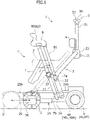
Figure 1] Figure 1 is a side view showing an electric walking assisting vehicle according to an Embodiment of the present invention. - [
Figure 2] Figure 2 is a block diagram showing a control system of the electric walking assisting vehicle according to the Embodiment of the present invention. - [
Figure 3] Figure 3 is a torque map for controlling the electric walking assisting vehicle according to the Embodiment of the present invention. - [
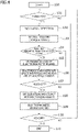
Figure 4] Figure 4 is a flowchart showing control of the electric walking assisting vehicle according to the Embodiment of the present invention. - [
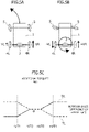
Figure 5] Figure 5A is a schematic plan view showing a turning assist,Figure 5B is a schematic plan view showing a turning assist on the spot (spin turn), andFigure 5C shows an additional torque map at turning time. - [
Figure 6] Figure 6A is a schematic side view showing an upward inclination compensation assist andFigure 6B is a schematic side view showing a downward inclination compensation assist. - [
Figure 7] Figure 7 is a schematic perspective view showing a lateral inclination compensation assist. - Hereinafter, an Embodiment of the present invention will be described in detail with reference to the accompanying drawings.
- In
Figure 1 , anelectric vehicle 1 according to the Embodiment of the present invention includes avehicle body 2, which is constituted of a moving base 21 (lower traveling body) and anupper frame 22 which is installed in a standing manner in the rear of the moving base 21 (a rear side base 24), and can be utilized in a walking assisting vehicle mode (1) indicated by a solid line inFigure 1 and a compact electric vehicle mode (riding mode 1') indicated by a two-dot chain line inFigure 1 . - The moving
base 21 includes the rear side base 24 (main body part) which is provided with left and right driving wheels 4 (rear wheels) and theupper frame 22 and afront side base 25 which is provided with left and right driven wheels 5 (front wheels), thefront side base 25 is coupled to a front side of therear side base 24 in a manner slidable in a front-rear direction, and a wheel base of the movingbase 21 is configured in such a way as to be extendable and contractible. - The left and right driving
wheels 4 are independently driven by left and right motor units 40 (40L and 40R) which are mounted on therear side base 24. The left and right drivenwheels 5 are constituted of universal wheels (omni-wheels or omnidirectional wheels), each of which includes, in a treading portion thereof,multiple rollers 50 which can rotate around an axis in a circumferential direction. Theelectric vehicle 1, as described later, can be steered, driven, and braked only by controlling the left andright motor units - The
upper frame 22 is of an inverse U-shape or a gate shape in which upper ends of a pair of left and right side part frames installed in a standing manner upward from both left and right side parts of therear side base 24 are joined by an upper end frame extending in a vehicle width direction, a lower end portion of astem 31 of arear handle 3 is rigidly coupled to a joiningpart 23 in a central portion of the upper end frame in the vehicle width direction, and a seat back 6 is supported on the joiningpart 23. - The
rear handle 3 is of a T-bar shape and has a pair of left and right gripping parts which extend from a connectingpart 32 with the upper end of thestem 31. The left and right gripping parts of therear handle 3 are provided with agripping sensor 30 which detects a state in which a user (or a helper) grips the gripping parts (hands-on). As thegripping sensor 30, a touch sensor such as a capacitance sensor and a pressure sensor can be used. In a case in which the user himself or herself uses the left and right gripping parts of therear handle 3 in the walking assisting vehicle mode (1) and a case in which a helper or the like steers the electric vehicle with the user seated on aseat 7, the left and right gripping parts thereof serve as an operation part. - In a bending portion of the upper frame 22 (side part frame) in the middle of a height direction, a base part of a
support frame 81 of an armrest 8 is fixed. A front end part of the armrest 8 on a right side, which is a depth side inFigure 1 , is provided with a ridingmode operation unit 83, and a front end part of the armrest 8 on a left side, which is a front side inFigure 1 , is provided with adisplay unit 80 on an upper surface of the gripping parts (83) having the same shapes. The ridingmode operation unit 83 is configured by a biaxial joystick, which is tiltable in a front-rear direction and a left-right direction, or the like. - Whereas a
support frame 71 of the seat 7 (seat cushion) is pivotably supported to a pivotal supportingpart 27, which protrudes forward from the bending portion of the upper frame 22 (side part frame), by ashaft 7a in the vehicle width direction, a lower end of thesupport frame 71 is coupled to the front side base 25 (pin) via acoupling part 7b (slot) in a pivotable and slidable manner. - By the above-described configuration, when the
seat 7 in a folding position is rotated rearward and upward from in the walking assisting vehicle mode (1) indicated by a solid line inFigure 1 and is thereby moved to a seating position 7' as indicated by a two-dot chain line inFigure 1 , in conjunction therewith, thefront side base 25 slides forward, themoving base 21 is extended, and the riding mode (1') is set. In this state, anupper surface 25b of thefront side base 25, which has moved to a front side of atray 24b, can be used as a foot rest for a passenger. - Conversely, when the
seat 7 is rotated frontward and downward from the riding mode (1') and is thereby moved to the folding position, thefront side base 25 slides backward, the movingbase 21 is shortened, and the walking assisting vehicle mode (1) in which the user can grip and operate therear handle 3 while standing and walking is set. -
Figure 2 is a block diagram showing a control system of theelectric vehicle 1. Theelectric vehicle 1 includes abattery 9 which supplies electric power to the left and right motor units 40 (40L and 40R) and acontrol unit 10 for controlling the left and right motor units 40 (40L and 40R), and thecontrol unit 10 includes an interlock mechanism which implements control corresponding to the walking assisting vehicle mode (1) and control corresponding to the riding mode (1'). - In the walking assisting vehicle mode (1), the riding
mode operation unit 83 is disabled, and based on detection information detected by aninclination sensor 20, left andright speed sensors 43, and the like and a previously set control map, thecontrol unit 10 executes control of the left and right motor units 40 (40L and 40R). Thegripping sensor 30 detects only gripping (hands-on/hands-off) of therear handle 3 by the user and is not involved in torque control of themotor units 40. - On the other hand, in the riding mode (1'), the
gripping sensor 30 is disabled, and based on an operation of the ridingmode operation unit 83 and detection information detected by theinclination sensor 20, thecontrol unit 10 executes control of the left and right motor units 40 (40L and 40R). - The
control unit 10 is constituted of: a computer (microcomputer) which includes ROM having stored therein programs and data for executing the control in the abovementioned modes, RAM which temporarily stores an arithmetic processing result, a CPU which performs arithmetic processing, and the like; a driving circuit (motor driver) for left andright motors 41; a power supply circuit including a relay which turns on/off the electric power of thebattery 9; and the like. - Each of the left and right motor units 40 (40L and 40R) includes a
motor 41, anelectromagnetic brake 42 for locking a rotor of themotor 41, and a rotation position sensor (43) for detecting a rotation position of themotor 41, and a driving shaft of themotor 41 is connected to each of driving wheels 4 (4L and 4R) via a deceleration gear, not shown, so as to be operable to transmit power thereto. - In the present Embodiment, each of the left and
right motors 41 is constituted of a brushless DC motor which switches a current of each phase coil by a driving circuit so as to match each phase of the rotor, which is detected by the rotation position sensor (43), and as described later, in the walking assisting vehicle mode (1), a rotation position sensor (Hall sensor) is used as arotation speed sensor 43. - In addition, the driving circuit of each of the left and
right motors 41 includes a current sensor for detecting a coil current. This coil current corresponds to torque of each of the left andright motors 41, and thecontrol unit 10 controls the coil current, thereby executing torque control of the left andright motors 41. - As the
electromagnetic brake 42, a negative operating type electromagnetic brake, which locks the driving shaft of themotor 41 in a non-excited state and unlocks the driving shaft thereof in an excited state, is suitable. In addition, an electromagneticbrake releasing switch 34 is provided so as to release locking of theelectromagnetic brake 42 and to allow theelectric vehicle 1 to be moved in case of emergency such as reduction in a battery remaining amount. - The
inclination sensor 20 is mounted on a circuit board of thecontrol unit 10 which is mounted inside the moving base 21 (rear side base 24) of thevehicle body 2, and a biaxial inclination sensor for detecting inclination of thevehicle body 2 in a front-rear direction and a lateral direction, an acceleration sensor, or a multiaxial inertial sensor in which an acceleration sensor and an angular acceleration sensor (gyroscope sensor) are integrated can be used. - The
electric vehicle 1 configured as described above is, in the walking assisting vehicle mode (1), operable to perform torque assist in all operations of forward moving/backward moving/turning by generating torque in the left and right motor units 40 (40L and 40R) in accordance with rotation speeds of the left andright driving wheels rotation speed sensors 43, in conjunction with operations of pushing/pulling thevehicle body 2 in a state in which the user grips therear handle 3. - First, basic control in the walking assisting vehicle mode (1) will be described by assuming forward moving/backward moving on a flat road.
-
Figure 3 shows a torque map which defines relationship between a rotation speed V detected by each of the left and rightrotation speed sensors 43 and a torque T command value of each of the left andright motors 41. As already described, in the present Embodiment, as the left and rightrotation speed sensors 43, the rotation position sensors of the left andright motors 41 are used, and a rotation speed of each of the left andright driving wheels - For example, in a case in which each of the left and
right motors 41 is a three-phase brushless DC motor, up to 1/6 rotation of 60 degrees can be detected by three rotation position sensors (43) which are arranged at intervals of 120 degrees, and since when the gear ratio of the deceleration gear is 10:1 and each of the left andright driving wheels - A basic operation in the walking assisting vehicle mode (1) is an operation of moving forward in a state in which the user grips the
rear handle 3. In the torque map shown inFigure 3 , an operation origin Vn (neutral point) is set on a slightly negative side of the rotation speed V in order for theelectric vehicle 1 not to move backward by initial rotation to a negative side (front side) in conjunction with an operation of gripping therear handle 3 by the user. - By this configuration, even when the initial rotation to the negative side, made by the operation of gripping the
rear handle 3 by the user, is detected, within the rotation speed Vn of each of the left andright driving wheels - In addition, the torque map shown in
Figure 3 has a peak region A1 (-Vn to +Va1) of a torque command value on a positive side of the operation origin Vn, which generates starting torque in the forward moving direction, and a peak region B1 (-Vn to -Vb1) of a torque command value on a negative side of the operation origin Vn, which generates starting torque in the backward moving direction. - By this configuration, in a state in which the
electric vehicle 1 is stopping, immediately in response to an operation of gripping and pushing therear handle 3 by the user, the torque assist is executed, and it is made possible to promptly start moving of theelectric vehicle 1 and to cause theelectric vehicle 1 to shift to steady forward traveling (A2). In addition, in response to an operation of pulling therear handle 3 by the user, it is made possible to cause theelectric vehicle 1 to promptly shift to steady backward traveling (B2). - Furthermore, the torque map shown in
Figure 3 has a steady torque region A2 (+Val to +Va2) in the forward moving direction, which is on a further positive side in the peak region A1 on the forward moving side and has a steady torque region B2 (-Vb1 to -Vb2) in the backward moving direction, which is on a further negative side in the peak region B1 on the backward moving side. - Although in order to compensate for frictional resistance which increases in accordance with a speed of the
electric vehicle 1, the steady torque region A2 (+Val to +Va2) in the forward moving direction increases in accordance with the rotation speed V, it is intended that torque assist be executed in accordance with a standard walking speed of an assumed user by a torque command value in the neighborhood of rating of each of the left andright motors 41. - Although something similar is applied also to the steady torque region B2 (-Vb1 to - Vb2) in the backward moving direction, because a walking speed during the backward moving is slow, as compared with a walking speed during the forward moving, it is preferable that a torque command value itself be less than that in the steady torque region A2 in the forward moving direction and an increasing rate of the torque command value in accordance with the rotation speed also be small, and the torque command value in the steady torque region B2 in an example shown in
Figure 3 is constant. - Furthermore, the torque map shown in
Figure 3 has a braking torque region A3 (+V2 to +V3) in the forward moving direction, which is on a further positive side in the steady torque region A2 on the forward moving side, and has a braking torque region B3 (-Vb2 to - Vb3) in the backward moving direction, which is on a further negative side in the steady torque region B2 on the backward moving side. - In the braking torque region A3 in the forward moving direction, a torque command value is decreased as a traveling speed of the
electric vehicle 1 approaches an upper limit in a standard walking speed range of the assumed user (for example, 6 km/h), braking torque is further generated for theelectric vehicle 1 by executing torque assist in a direction inverse to a traveling direction in the neighborhood of the upper limit in the assumed walking speed range, and a traveling speed of theelectric vehicle 1 is controlled to fall within the assumed walking speed range. - Although the similar is applied also to the braking torque region B3 in the backward moving direction, because a walking speed during the backward moving is slow, as compared with a walking speed during the forward moving, braking torque of a lower rotation speed lower than a rotation speed on the forward moving side is generated.
- As described hereinbefore, the torque command values in accordance with the peak region A1 (starting torque region), the steady torque region A2, and the braking torque region A3 in the forward moving direction are given by the torque map shown in
Figure 3 , the operation of gripping and pushing therear handle 3 by the user is thereby further promptly started and shifting to the steady torque region A2 is performed, and thereafter, by exceeding the steady torque region A2 and increasing the speed, the torque assist in a braking direction is executed in the braking torque region A3, and when deceleration to a value not greater than values in the steady torque region A2 is performed, the torque assist in a speed increasing direction is executed in the peak region A1. Therefore, the steady torque region A2 corresponding to the standard walking speed range (+Val to +Va2) is maintained only by the simple operation of gripping and pushing/pulling therear handle 3 by the user without special awareness of the user, thus leading to advantages in that stable assist can be performed. - In addition, in the above-described torque assist control, increase and decrease of the rotation speed V by the operations of gripping and pushing/pulling the
rear handle 3 by the user and increase and decrease of the rotation speed V by driving of the left and right motors 41 (torque assist) are not distinguished (it is not necessary to distinguish therebetween), and the torque assist is executed in accordance with the rotation speed V as a result of cooperative operations of the operation of gripping and pushing therear handle 3 by the user and the operation by the driving force of the left andright motors 41. Therefore, not only is a force sensor (pressure sensor or the like) which detects a direction and a magnitude of a force with which the user pushes/pulls therear handle 3 unnecessary, but also the control is not influenced by variation in the direction and the magnitude of a detected force, thus leading to advantages in that a vehicle body structure and control are simplified. - Next, a turning assist in the walking assisting vehicle mode (1) will be described with reference to
Figures 5A to 5C . - As already described, in the
electric vehicle 1, each of the motor units 40 (40L and 40R) of the left andright driving wheels rotation speed sensor 43, and in a case in which the operation of pushing/pulling thevehicle body 2 is performed with left and right forces which are different from each other in a state in which the user grips therear handle 3 by left and right hands (or either one of the hands), a difference between rotation speeds of the left andright driving wheels - For example, as shown in
Figure 5A , by relatively strongly pushing a right side of therear handle 3, a rotation speed VR, which is greater than a rotation speed VL of thedriving wheel 4L on a left side, is detected for thedriving wheel 4R on the right side, and a rotation speed difference ΔV=VR-VL between the rotation speeds VR and VL detected by the left and rightrotation speed sensors 43 is caused. Here, when the torque map shown inFigure 3 is applied to control of the motor units 40 (40L and 40R) of the left andright driving wheels electric vehicle 1 turns, and stable forward moving/backward moving cannot be thereby performed. - Therefore, as shown in
Figure 5C , a torque assist in accordance with the rotation speed difference ΔV is executed as described below by a torque map which defines relationship between the rotation speed difference ΔV of the left andright driving wheels - (i) When the rotation speed difference ΔV of the left and
right driving wheels right driving wheels Figure 3 , torque of either one of the left and right rotation speeds VR and VL or torque, which is selected from mean values (average values) of the left and right rotation speeds VR and VL and is equal in principle, is generated in the left and right motor units 40 (40L and 40R), and the forward moving/backward moving assist is executed. - (ii) When the rotation speed difference ΔV of the left and
right driving wheels - (iii) However, when the rotation speed difference ΔV of the left and
right driving wheels - By performing the above-described turning assist control, steering resistance caused on the driven
wheels 5 is compensated, light and reliable turning assist can be executed by an operation of pushing one side of therear handle 3. In addition, as shown inFigure 5B , a light and reliable turning (spin turn) assist on the spot can be executed by operations of pushing one side of therear handle 3 and pulling the other side thereof. - Next, an uphill/downhill assist in the walking assisting vehicle mode (1) will be described with reference to
Figures 6A to 6C . - In the description given hereinbefore, for the sake of convenience, the control on a flat road is described. However, on an
uphill road 91 shown inFigure 6A and adownhill road 92 shown inFigure 6B , due to a gravity exerted on thevehicle body 2, loads (mg·sinθp) in a direction inverse to a traveling direction/a direction same as the traveling direction are caused in accordance with a vehicle weight m and an inclination θp. - Therefore, on the
uphill road 91 and thedownhill road 92, a torque map shown inFigure 6C is used in combination, and compensation torque Tca, Tcb, and Td which offset the loads caused in accordance with the inclination (angle) θp which is detected by theinclination sensor 20 are added to a torque command value. - Note that a threshold value (less than ±θρ1 and a dead zone) is set for the inclination θρ, and in a case in which the inclination θp is less than the threshold value and no influence is exerted on the basic control and the turning control, the torque compensation is not performed.
- (i) When the
electric vehicle 1 goes up on theuphill road 91 having an inclination θp1 or more and moves forward, in order to offset a load in an inverse direction, which is weighted in accordance with the inclination θp of theuphill road 91, as indicated by a solid line on a right side of the torque map inFigure 6C , compensation torque Tca in the same direction, which increases in proportion to the inclination θp of theuphill road 91 is added and an uphill assist is executed. - (ii) When the
electric vehicle 1 goes down on theuphill road 91 having the inclination θp1 or more and moves downward, since a load in the same direction as a backward moving direction, which is weighted in accordance with the inclination θp of theuphill road 91, is caused, as indicated by a solid line on a left side of the torque map inFigure 6C , compensation torque Tcb in an inverse direction (regeneration direction), which increases in proportion to the inclination θp of theuphill road 91 is added and a braking assist is executed. - (iii) When the
electric vehicle 1 goes down on thedownhill road 92 having the inclination θp1 or more and moves forward, since a load in the same direction as the traveling direction, which is weighted in accordance with the inclination θp of thedownhill road 92, is caused, as indicated by a solid line and a broken line on the left side of the torque map inFigure 6C , compensation torque Td in an inverse direction (regeneration direction), which increases in proportion to an inclination θp of thedownhill road 92, is added and a braking assist is executed, similarly. However, when the inclination θp has reached a predetermined threshold value, predetermined braking torque is generated and braking control is executed. -
Figure 7 shows a lateral inclination compensation assist in a case in which theelectric vehicle 1 in the walking assisting vehicle mode (1) moves forward on aroad surface 93 which has an inclination (lateral inclination θr) in a direction intersecting with a traveling direction of the electric vehicle 1 (or a case in which theelectric vehicle 1 moves forward in a direction intersecting with the inclination θr of the slope 93). - In other words, in
Figure 7 , in a case in which there is a center of gravity with a distance L which lies ahead with respect to an axle of thedriving wheels electric vehicle 1 by gravity mg acting on the center of gravity and the lateral inclination θr. - Therefore, in order to offset this deflection moment by assist torque by the motor units 40 (40L and 40R) of the left and
right driving wheels driving wheels 
- Note that a threshold value (dead zone) is set also for the lateral inclination θr and in a case in which the lateral inclination θr is less than the threshold value and no influence is exerted on the basic control and the turning control, the lateral inclination compensation assist is not performed.
- When the
electric vehicle 1 configured as described above is turned on by operating a key 11 and the system is activated, in accordance with a frame form when activated, the walking assisting vehicle mode (1) or the riding mode (1') is set. Note that as already described, in a state in which theelectric vehicle 1 is stopping, theelectromagnetic brake 42 is in a locked state. - Hereinafter, control in a case in which the walking assisting vehicle mode (1) is set when activated or the walking assisting vehicle mode (1) is set by an operation performed by the user in a state in which the
electric vehicle 1 is stopping after the activation will be described with reference to a flowchart inFigure 4 . - First, when the walking assisting vehicle mode (1) is set (step 100), the gripping
sensor 30 is in an operation state. In this state, when the user grips therear handle 3 and the grippingsensor 30 detects a gripping state (hands-on) (step 101), theinclination sensor 20 detects the inclination θp in the forward-backward direction of thevehicle body 2 and the inclination θr in a lateral direction (step 102). - When the inclination θp in the forward-backward direction and/or the inclination θr in the lateral direction are/is equal to or greater than the threshold value, torque assist in which the compensation torque Tca, Tcb, and Td and/or the compensation torque TaL and TaR are generated in the left and right motor units 40 (40L and 40R) is executed and in a neutral state in which initial torque in a forward moving direction is applied to the left and
right driving wheels electric vehicle 1 stands by (step 103). - Subsequently, it is checked whether or not the left and right
electromagnetic brakes 42 are in a locked state (step 104), and when the left and rightelectromagnetic brakes 42 are in the locked state (at initial activation time or the like), lock of the left and rightelectromagnetic brakes 42 is released (step 105). - At this time, although the
electric vehicle 1 is at rest, an external force resulting from the inclination is offset by compensation torque, and regardless of absence or presence of the inclination, theelectric vehicle 1 is in an immediately movable state. In this state, the user performs the operation of pushing/pulling therear handle 3, whereby the left andright driving wheels rotation speed sensor 43, in accordance with the rotation speeds V (VL and VR) and the torque map, torque is generated in the left and right motor units 40 (40L and 40R), and the torque assist such as the forward moving/backward moving/turning is executed (step 106). - Also, while the
electric vehicle 1 is traveling, detection of the gripping state (hands-on) by the grippingsensor 30 is continued (step 107), and when the gripping state comes not to be detected by the grippingsensor 30 and thecontrol unit 10 determines hands-off, torque command values for the left and right motor units 40 (40L and 40R) are gradually decreased, and torque assist in which theelectric vehicle 1 is decelerated and stopped is executed (step 108). Together therewith, after a lapse of predetermined time (for example, two seconds) from the hands-off, the left and rightelectromagnetic brakes 42 are locked (step 109). - In a state in which the left and right
electromagnetic brakes 42 are locked, when an operation of turning off the key 11 is detected (step 110), electric power supply to the left and right motor units 40 (40L and 40R) is stopped and thereafter, the system is shut down (step 111). - Hereinbefore, the Embodiment of the present invention is described. However, the present invention is not limited to the above-described Embodiment, and a variety of variations and modifications of the present invention can be further made based on the technical concept of the present invention.
- For example, although in the Embodiment described above, the case in which the electric
walking assisting vehicle 1 includes the compact electric vehicle mode (riding mode) is described, the present invention can be implemented as an electric walking assisting vehicle including no riding mode. - In addition, although in the Embodiment described above, the case in which, as the driven
wheels 5, the omni-wheels are used is described, caster-type universal wheels can also be used. -
- 1
- Electric vehicle
- 2
- Vehicle body
- 3
- Rear handle (gripping part)
- 4
- Driving wheel (rear wheel)
- 5
- Driven wheel (universal wheel, front wheel)
- 6
- Seat back
- 7
- Seat
- 8
- Armrest
- 9
- Battery
- 10
- Control unit
- 20
- Inclination sensor
- 21
- Moving base
- 22
- Upper frame
- 24
- Rear side base
- 25
- Front side base
- 30
- Gripping sensor (touch sensor)
- 34
- Electromagnetic brake releasing switch
- 40 (40L and 40R)
- Motor units
- 41
- Left and right motors
- 42
- Left and right electromagnetic brakes
- 43
- Left and right rotation speed sensors
- 80
- Display unit
- 83
- Riding mode operation unit
Claims (11)
- An electric walking assisting vehicle comprising:a vehicle body having a forward-backward direction and a width direction;left and right driving wheels provided spaced apart in the width direction of the vehicle body;left and right motors connected so as to respectively transmit power to the left and right driving wheels;universal wheels provided spaced apart from the left and right driving wheels in the forward-backward direction of the vehicle body;a gripping part provided in an upper portion of the vehicle body so as to be gripped by a user in a standing and walking posture;a gripping sensor for detecting that the gripping part is gripped by the user;left and right rotation speed sensors for individually detecting rotation speeds of the left and right driving wheels; anda control unit for controlling the left and right motors,wherein the control unit is configured to generate torque in the left and right motors in accordance with a torque map which defines relationships between the rotation speeds of the left and right driving wheels detected by the left and right rotation speed sensors and torque command values of the left and right motors in a state in which the gripping sensor is detecting the gripping.
- The electric walking assisting vehicle according to claim 1, wherein in the torque map, an operation origin is set on a negative side in a rotation direction of the left and right driving wheels, the rotation direction being detected by the left and right rotation speed sensors, and the torque map has a peak region on a positive side of the operation origin, starting torque in a forward moving direction being generated in the peak region on the positive side, and has a peak region on a negative side of the operation origin, starting torque in a backward moving direction being generated in the peak region on the negative side.
- The electric walking assisting vehicle according to claim 2, wherein the torque map has a steady torque region in the forward moving direction on a further positive side in the peak region on the positive side, has a steady torque region in the backward moving direction on a further negative side in the peak region on the negative side, and a torque command value in the steady torque region on the negative side is less than a torque command value in the steady torque region on the positive side and/or an increasing rate of the torque command value in accordance with a rotation speed in the steady torque region on the negative side is less than an increasing rate of the torque command value in accordance with a rotation speed in the steady torque region on the positive side.
- The electric walking assisting vehicle according to claim 3, wherein the torque map has a braking torque region in the forward moving direction on a further positive side in the steady torque region on the positive side and has a braking torque region in the backward moving direction on a further negative side in the steady torque region on the negative side.
- The electric walking assisting vehicle according to any one of claims 1 to 4, wherein the control unit is configured such that when a rotation speed difference of the left and right driving wheels is less than a predetermined threshold value, the rotation speed difference being detected by the left and right rotation speed sensors, the control unit ignores the rotation speed difference of the left and right driving wheels, and in accordance with any of the rotation speeds of the left and right driving wheels or a torque command value selected from mean values of the rotation speeds, the control unit executes torque assist.
- The electric walking assisting vehicle according to claim 5, wherein the control unit is configured such that when the rotation speed difference is equal to or greater than the predetermined threshold value, in accordance with the rotation speed difference, the control unit executes turning assist control so as to increase a torque command value of one of the motors, the rotation speed of which is greater than the rotation speed of another one of the motors and decreases a torque command value of one of the motors, the rotation speed of which is less than the rotation speed of another one of the motors.
- The electric walking assisting vehicle according to any one of claims 1 to 6, further comprising:an electromagnetic brake for locking the left and right driving wheels or the left and right motors; andan inclination sensor for detecting an inclination in each of a forward-backward direction and a lateral direction of the vehicle body, whereinthe control unit is configured such that in a state in which the gripping sensor has detected the gripping, the control unit sets the inclination sensor in an operating state, executes neutral standby control in which in accordance with an inclination detected by the inclination sensor, compensation torque offsetting a rotation force generated on the left and right driving wheels by a gravity exerted on the vehicle body is generated for the left and right motors, and in a state in which the compensation torque is generated, the control unit unlocks the electromagnetic brake.
- The electric walking assisting vehicle according to any one of claims 1 to 7, wherein the control unit is configured such that when the rotation speed difference of the left and right driving wheels is equal to or greater than the predetermined threshold value, the rotation speed difference being detected by the left and right rotation speed sensors, and a rotation speed of one of the driving wheels, the rotation speed of which is greater than a rotation speed of another one of the driving wheels, is equal to or greater than an upper limit value, the control unit sets a torque command value of the one of the driving wheels to zero.
- The electric walking assisting vehicle according to claim 7 or 8, wherein the control unit is configured such that when during torque control for the left and right motors in accordance with rotation speeds of the left and right driving wheels, the gripping sensor comes not to detect the gripping, the control unit gradually decreases torque command values of the left and right motors and after predetermined time, sets the electromagnetic brake in a locked state.
- The electric walking assisting vehicle according to any one of claims 7 to 9, further comprising a releasing part which releases lock of the electromagnetic brake during stopping of the left and right motors.
- The electric walking assisting vehicle according to any one of claims 1 to 10, wherein the vehicle body includes a foldable seat and an operation part which is operable by the user seated on the seat, and the electric walking assisting vehicle is usable as a compact electric vehicle.
Applications Claiming Priority (1)
| Application Number | Priority Date | Filing Date | Title |
|---|---|---|---|
| JP2020207549A JP7519031B2 (en) | 2020-12-15 | 2020-12-15 | Electric walking aid |
Publications (2)
| Publication Number | Publication Date |
|---|---|
| EP4014942A1 true EP4014942A1 (en) | 2022-06-22 |
| EP4014942B1 EP4014942B1 (en) | 2023-04-26 |
Family
ID=80112197
Family Applications (1)
| Application Number | Title | Priority Date | Filing Date |
|---|---|---|---|
| EP21212921.7A Active EP4014942B1 (en) | 2020-12-15 | 2021-12-07 | Electric walking assisting vehicle |
Country Status (3)
| Country | Link |
|---|---|
| US (1) | US12193989B2 (en) |
| EP (1) | EP4014942B1 (en) |
| JP (1) | JP7519031B2 (en) |
Cited By (1)
| Publication number | Priority date | Publication date | Assignee | Title |
|---|---|---|---|---|
| EP4344525A1 (en) * | 2022-09-27 | 2024-04-03 | Nanjing Chervon Industry Co., Ltd. | Walk-behind electric device |
Families Citing this family (6)
| Publication number | Priority date | Publication date | Assignee | Title |
|---|---|---|---|---|
| US11806303B2 (en) * | 2021-06-28 | 2023-11-07 | Ubtech North America Research And Development Center Corp | Robotic walking assistant |
| JP2024529991A (en) * | 2022-01-26 | 2024-08-14 | 浙江益恒悦医療科技有限公司 | Method for controlling steering assist force of walking aid, steering assist force control device, and memory |
| CN118786821A (en) * | 2023-04-13 | 2024-10-18 | 南京泉峰科技有限公司 | Power-assisted working machines and lawn mowers |
| CN117813995A (en) * | 2022-09-29 | 2024-04-05 | 南京泉峰科技有限公司 | Method for estimating push and pull forces of power-assisted working machines and lawn mowers |
| US20240099185A1 (en) * | 2022-09-27 | 2024-03-28 | Nanjing Chervon Industry Co., Ltd. | Walk-behind electric device |
| EP4623883A1 (en) * | 2024-03-27 | 2025-10-01 | Linak A/S | A mobile wheeled device with a driven wheel |
Citations (5)
| Publication number | Priority date | Publication date | Assignee | Title |
|---|---|---|---|---|
| JPH0320326B2 (en) | 1983-05-13 | 1991-03-19 | Honda Motor Co Ltd | |
| JP2012045990A (en) * | 2010-08-25 | 2012-03-08 | Toyota Motor Corp | Electric power steering device |
| US20150066278A1 (en) * | 2013-08-30 | 2015-03-05 | Funai Electric Co., Ltd. | Manually propelled vehicle |
| EP2848239A1 (en) * | 2013-08-30 | 2015-03-18 | Funai Electric Advanced Applied Technology Research Institute Inc. | Walking assistance moving vehicle |
| JP6620326B2 (en) * | 2015-07-02 | 2019-12-18 | Rt.ワークス株式会社 | Wheelbarrow |
Family Cites Families (8)
| Publication number | Priority date | Publication date | Assignee | Title |
|---|---|---|---|---|
| JPH07212911A (en) * | 1994-01-25 | 1995-08-11 | Toyota Motor Corp | Electric vehicle speed control device |
| WO2014188726A1 (en) * | 2013-05-22 | 2014-11-27 | ナブテスコ株式会社 | Electric walking assistance device, program for controlling electric walking assistance device, and method of controlling electric walking assistance device |
| WO2015053245A1 (en) | 2013-10-10 | 2015-04-16 | 株式会社村田製作所 | Pushcart |
| JP6319444B2 (en) * | 2014-07-23 | 2018-05-09 | 株式会社村田製作所 | Wheelbarrow |
| JP5960304B1 (en) | 2015-01-28 | 2016-08-02 | シャープ株式会社 | Walking assistance vehicle |
| CN107303235A (en) * | 2016-04-19 | 2017-10-31 | 李书贤 | Modular electric wheel set of walking aid |
| US10639226B1 (en) * | 2017-02-23 | 2020-05-05 | Koby Keyes Product Design, LLC | Mobility assistance apparatus |
| JP7185849B2 (en) | 2019-04-05 | 2022-12-08 | スズキ株式会社 | moving body |
-
2020
- 2020-12-15 JP JP2020207549A patent/JP7519031B2/en active Active
-
2021
- 2021-12-07 EP EP21212921.7A patent/EP4014942B1/en active Active
- 2021-12-08 US US17/545,398 patent/US12193989B2/en active Active
Patent Citations (5)
| Publication number | Priority date | Publication date | Assignee | Title |
|---|---|---|---|---|
| JPH0320326B2 (en) | 1983-05-13 | 1991-03-19 | Honda Motor Co Ltd | |
| JP2012045990A (en) * | 2010-08-25 | 2012-03-08 | Toyota Motor Corp | Electric power steering device |
| US20150066278A1 (en) * | 2013-08-30 | 2015-03-05 | Funai Electric Co., Ltd. | Manually propelled vehicle |
| EP2848239A1 (en) * | 2013-08-30 | 2015-03-18 | Funai Electric Advanced Applied Technology Research Institute Inc. | Walking assistance moving vehicle |
| JP6620326B2 (en) * | 2015-07-02 | 2019-12-18 | Rt.ワークス株式会社 | Wheelbarrow |
Cited By (1)
| Publication number | Priority date | Publication date | Assignee | Title |
|---|---|---|---|---|
| EP4344525A1 (en) * | 2022-09-27 | 2024-04-03 | Nanjing Chervon Industry Co., Ltd. | Walk-behind electric device |
Also Published As
| Publication number | Publication date |
|---|---|
| JP7519031B2 (en) | 2024-07-19 |
| US12193989B2 (en) | 2025-01-14 |
| US20220183920A1 (en) | 2022-06-16 |
| EP4014942B1 (en) | 2023-04-26 |
| JP2022094589A (en) | 2022-06-27 |
Similar Documents
| Publication | Publication Date | Title |
|---|---|---|
| EP4014942B1 (en) | Electric walking assisting vehicle | |
| EP4029487B1 (en) | Electric walking assisting vehicle | |
| TWI735815B (en) | vehicle | |
| EP2862553A2 (en) | Manually propelled vehicle | |
| EP4035926B1 (en) | Small electric vehicle | |
| EP3696067A1 (en) | Vehicle | |
| US11813211B2 (en) | Small electric vehicle | |
| JP7636715B2 (en) | Small electric vehicle | |
| JP7567489B2 (en) | Electric walking aid | |
| EP4035927B1 (en) | Small electric vehicle | |
| EP4119113B1 (en) | Small electric vehicle | |
| JP7557700B2 (en) | Small electric vehicle | |
| TWM607015U (en) | Electric three-wheeled vehicle | |
| JPH10234786A (en) | Electric wheelchair |
Legal Events
| Date | Code | Title | Description |
|---|---|---|---|
| PUAI | Public reference made under article 153(3) epc to a published international application that has entered the european phase |
Free format text: ORIGINAL CODE: 0009012 |
|
| STAA | Information on the status of an ep patent application or granted ep patent |
Free format text: STATUS: REQUEST FOR EXAMINATION WAS MADE |
|
| 17P | Request for examination filed |
Effective date: 20211207 |
|
| AK | Designated contracting states |
Kind code of ref document: A1 Designated state(s): AL AT BE BG CH CY CZ DE DK EE ES FI FR GB GR HR HU IE IS IT LI LT LU LV MC MK MT NL NO PL PT RO RS SE SI SK SM TR |
|
| GRAP | Despatch of communication of intention to grant a patent |
Free format text: ORIGINAL CODE: EPIDOSNIGR1 |
|
| STAA | Information on the status of an ep patent application or granted ep patent |
Free format text: STATUS: GRANT OF PATENT IS INTENDED |
|
| RIC1 | Information provided on ipc code assigned before grant |
Ipc: A61G 5/04 20130101ALI20221122BHEP Ipc: A61H 3/04 20060101AFI20221122BHEP |
|
| INTG | Intention to grant announced |
Effective date: 20221212 |
|
| GRAJ | Information related to disapproval of communication of intention to grant by the applicant or resumption of examination proceedings by the epo deleted |
Free format text: ORIGINAL CODE: EPIDOSDIGR1 |
|
| STAA | Information on the status of an ep patent application or granted ep patent |
Free format text: STATUS: REQUEST FOR EXAMINATION WAS MADE |
|
| GRAS | Grant fee paid |
Free format text: ORIGINAL CODE: EPIDOSNIGR3 |
|
| STAA | Information on the status of an ep patent application or granted ep patent |
Free format text: STATUS: GRANT OF PATENT IS INTENDED |
|
| GRAP | Despatch of communication of intention to grant a patent |
Free format text: ORIGINAL CODE: EPIDOSNIGR1 |
|
| INTC | Intention to grant announced (deleted) | ||
| GRAA | (expected) grant |
Free format text: ORIGINAL CODE: 0009210 |
|
| STAA | Information on the status of an ep patent application or granted ep patent |
Free format text: STATUS: THE PATENT HAS BEEN GRANTED |
|
| INTG | Intention to grant announced |
Effective date: 20230310 |
|
| AK | Designated contracting states |
Kind code of ref document: B1 Designated state(s): AL AT BE BG CH CY CZ DE DK EE ES FI FR GB GR HR HU IE IS IT LI LT LU LV MC MK MT NL NO PL PT RO RS SE SI SK SM TR |
|
| REG | Reference to a national code |
Ref country code: GB Ref legal event code: FG4D |
|
| REG | Reference to a national code |
Ref country code: CH Ref legal event code: EP |
|
| REG | Reference to a national code |
Ref country code: DE Ref legal event code: R096 Ref document number: 602021002077 Country of ref document: DE |
|
| REG | Reference to a national code |
Ref country code: AT Ref legal event code: REF Ref document number: 1562329 Country of ref document: AT Kind code of ref document: T Effective date: 20230515 |
|
| REG | Reference to a national code |
Ref country code: IE Ref legal event code: FG4D |
|
| REG | Reference to a national code |
Ref country code: LT Ref legal event code: MG9D |
|
| REG | Reference to a national code |
Ref country code: NL Ref legal event code: MP Effective date: 20230426 |
|
| REG | Reference to a national code |
Ref country code: AT Ref legal event code: MK05 Ref document number: 1562329 Country of ref document: AT Kind code of ref document: T Effective date: 20230426 |
|
| PG25 | Lapsed in a contracting state [announced via postgrant information from national office to epo] |
Ref country code: NL Free format text: LAPSE BECAUSE OF FAILURE TO SUBMIT A TRANSLATION OF THE DESCRIPTION OR TO PAY THE FEE WITHIN THE PRESCRIBED TIME-LIMIT Effective date: 20230426 |
|
| PG25 | Lapsed in a contracting state [announced via postgrant information from national office to epo] |
Ref country code: SE Free format text: LAPSE BECAUSE OF FAILURE TO SUBMIT A TRANSLATION OF THE DESCRIPTION OR TO PAY THE FEE WITHIN THE PRESCRIBED TIME-LIMIT Effective date: 20230426 Ref country code: PT Free format text: LAPSE BECAUSE OF FAILURE TO SUBMIT A TRANSLATION OF THE DESCRIPTION OR TO PAY THE FEE WITHIN THE PRESCRIBED TIME-LIMIT Effective date: 20230828 Ref country code: NO Free format text: LAPSE BECAUSE OF FAILURE TO SUBMIT A TRANSLATION OF THE DESCRIPTION OR TO PAY THE FEE WITHIN THE PRESCRIBED TIME-LIMIT Effective date: 20230726 Ref country code: ES Free format text: LAPSE BECAUSE OF FAILURE TO SUBMIT A TRANSLATION OF THE DESCRIPTION OR TO PAY THE FEE WITHIN THE PRESCRIBED TIME-LIMIT Effective date: 20230426 Ref country code: AT Free format text: LAPSE BECAUSE OF FAILURE TO SUBMIT A TRANSLATION OF THE DESCRIPTION OR TO PAY THE FEE WITHIN THE PRESCRIBED TIME-LIMIT Effective date: 20230426 |
|
| PG25 | Lapsed in a contracting state [announced via postgrant information from national office to epo] |
Ref country code: RS Free format text: LAPSE BECAUSE OF FAILURE TO SUBMIT A TRANSLATION OF THE DESCRIPTION OR TO PAY THE FEE WITHIN THE PRESCRIBED TIME-LIMIT Effective date: 20230426 Ref country code: PL Free format text: LAPSE BECAUSE OF FAILURE TO SUBMIT A TRANSLATION OF THE DESCRIPTION OR TO PAY THE FEE WITHIN THE PRESCRIBED TIME-LIMIT Effective date: 20230426 Ref country code: LV Free format text: LAPSE BECAUSE OF FAILURE TO SUBMIT A TRANSLATION OF THE DESCRIPTION OR TO PAY THE FEE WITHIN THE PRESCRIBED TIME-LIMIT Effective date: 20230426 Ref country code: LT Free format text: LAPSE BECAUSE OF FAILURE TO SUBMIT A TRANSLATION OF THE DESCRIPTION OR TO PAY THE FEE WITHIN THE PRESCRIBED TIME-LIMIT Effective date: 20230426 Ref country code: IS Free format text: LAPSE BECAUSE OF FAILURE TO SUBMIT A TRANSLATION OF THE DESCRIPTION OR TO PAY THE FEE WITHIN THE PRESCRIBED TIME-LIMIT Effective date: 20230826 Ref country code: HR Free format text: LAPSE BECAUSE OF FAILURE TO SUBMIT A TRANSLATION OF THE DESCRIPTION OR TO PAY THE FEE WITHIN THE PRESCRIBED TIME-LIMIT Effective date: 20230426 Ref country code: GR Free format text: LAPSE BECAUSE OF FAILURE TO SUBMIT A TRANSLATION OF THE DESCRIPTION OR TO PAY THE FEE WITHIN THE PRESCRIBED TIME-LIMIT Effective date: 20230727 |
|
| PG25 | Lapsed in a contracting state [announced via postgrant information from national office to epo] |
Ref country code: FI Free format text: LAPSE BECAUSE OF FAILURE TO SUBMIT A TRANSLATION OF THE DESCRIPTION OR TO PAY THE FEE WITHIN THE PRESCRIBED TIME-LIMIT Effective date: 20230426 |
|
| PG25 | Lapsed in a contracting state [announced via postgrant information from national office to epo] |
Ref country code: SK Free format text: LAPSE BECAUSE OF FAILURE TO SUBMIT A TRANSLATION OF THE DESCRIPTION OR TO PAY THE FEE WITHIN THE PRESCRIBED TIME-LIMIT Effective date: 20230426 |
|
| REG | Reference to a national code |
Ref country code: DE Ref legal event code: R097 Ref document number: 602021002077 Country of ref document: DE |
|
| PG25 | Lapsed in a contracting state [announced via postgrant information from national office to epo] |
Ref country code: SM Free format text: LAPSE BECAUSE OF FAILURE TO SUBMIT A TRANSLATION OF THE DESCRIPTION OR TO PAY THE FEE WITHIN THE PRESCRIBED TIME-LIMIT Effective date: 20230426 Ref country code: SK Free format text: LAPSE BECAUSE OF FAILURE TO SUBMIT A TRANSLATION OF THE DESCRIPTION OR TO PAY THE FEE WITHIN THE PRESCRIBED TIME-LIMIT Effective date: 20230426 Ref country code: RO Free format text: LAPSE BECAUSE OF FAILURE TO SUBMIT A TRANSLATION OF THE DESCRIPTION OR TO PAY THE FEE WITHIN THE PRESCRIBED TIME-LIMIT Effective date: 20230426 Ref country code: EE Free format text: LAPSE BECAUSE OF FAILURE TO SUBMIT A TRANSLATION OF THE DESCRIPTION OR TO PAY THE FEE WITHIN THE PRESCRIBED TIME-LIMIT Effective date: 20230426 Ref country code: DK Free format text: LAPSE BECAUSE OF FAILURE TO SUBMIT A TRANSLATION OF THE DESCRIPTION OR TO PAY THE FEE WITHIN THE PRESCRIBED TIME-LIMIT Effective date: 20230426 Ref country code: CZ Free format text: LAPSE BECAUSE OF FAILURE TO SUBMIT A TRANSLATION OF THE DESCRIPTION OR TO PAY THE FEE WITHIN THE PRESCRIBED TIME-LIMIT Effective date: 20230426 |
|
| PLBE | No opposition filed within time limit |
Free format text: ORIGINAL CODE: 0009261 |
|
| STAA | Information on the status of an ep patent application or granted ep patent |
Free format text: STATUS: NO OPPOSITION FILED WITHIN TIME LIMIT |
|
| 26N | No opposition filed |
Effective date: 20240129 |
|
| PG25 | Lapsed in a contracting state [announced via postgrant information from national office to epo] |
Ref country code: SI Free format text: LAPSE BECAUSE OF FAILURE TO SUBMIT A TRANSLATION OF THE DESCRIPTION OR TO PAY THE FEE WITHIN THE PRESCRIBED TIME-LIMIT Effective date: 20230426 |
|
| PG25 | Lapsed in a contracting state [announced via postgrant information from national office to epo] |
Ref country code: SI Free format text: LAPSE BECAUSE OF FAILURE TO SUBMIT A TRANSLATION OF THE DESCRIPTION OR TO PAY THE FEE WITHIN THE PRESCRIBED TIME-LIMIT Effective date: 20230426 Ref country code: IT Free format text: LAPSE BECAUSE OF FAILURE TO SUBMIT A TRANSLATION OF THE DESCRIPTION OR TO PAY THE FEE WITHIN THE PRESCRIBED TIME-LIMIT Effective date: 20230426 |
|
| PG25 | Lapsed in a contracting state [announced via postgrant information from national office to epo] |
Ref country code: LU Free format text: LAPSE BECAUSE OF NON-PAYMENT OF DUE FEES Effective date: 20231207 |
|
| PG25 | Lapsed in a contracting state [announced via postgrant information from national office to epo] |
Ref country code: MC Free format text: LAPSE BECAUSE OF FAILURE TO SUBMIT A TRANSLATION OF THE DESCRIPTION OR TO PAY THE FEE WITHIN THE PRESCRIBED TIME-LIMIT Effective date: 20230426 |
|
| REG | Reference to a national code |
Ref country code: BE Ref legal event code: MM Effective date: 20231231 |
|
| PG25 | Lapsed in a contracting state [announced via postgrant information from national office to epo] |
Ref country code: MC Free format text: LAPSE BECAUSE OF FAILURE TO SUBMIT A TRANSLATION OF THE DESCRIPTION OR TO PAY THE FEE WITHIN THE PRESCRIBED TIME-LIMIT Effective date: 20230426 Ref country code: LU Free format text: LAPSE BECAUSE OF NON-PAYMENT OF DUE FEES Effective date: 20231207 |
|
| REG | Reference to a national code |
Ref country code: IE Ref legal event code: MM4A |
|
| PG25 | Lapsed in a contracting state [announced via postgrant information from national office to epo] |
Ref country code: IE Free format text: LAPSE BECAUSE OF NON-PAYMENT OF DUE FEES Effective date: 20231207 |
|
| PG25 | Lapsed in a contracting state [announced via postgrant information from national office to epo] |
Ref country code: BE Free format text: LAPSE BECAUSE OF NON-PAYMENT OF DUE FEES Effective date: 20231231 |
|
| PG25 | Lapsed in a contracting state [announced via postgrant information from national office to epo] |
Ref country code: IE Free format text: LAPSE BECAUSE OF NON-PAYMENT OF DUE FEES Effective date: 20231207 Ref country code: BE Free format text: LAPSE BECAUSE OF NON-PAYMENT OF DUE FEES Effective date: 20231231 |
|
| PG25 | Lapsed in a contracting state [announced via postgrant information from national office to epo] |
Ref country code: BG Free format text: LAPSE BECAUSE OF FAILURE TO SUBMIT A TRANSLATION OF THE DESCRIPTION OR TO PAY THE FEE WITHIN THE PRESCRIBED TIME-LIMIT Effective date: 20230426 |
|
| PG25 | Lapsed in a contracting state [announced via postgrant information from national office to epo] |
Ref country code: BG Free format text: LAPSE BECAUSE OF FAILURE TO SUBMIT A TRANSLATION OF THE DESCRIPTION OR TO PAY THE FEE WITHIN THE PRESCRIBED TIME-LIMIT Effective date: 20230426 |
|
| PG25 | Lapsed in a contracting state [announced via postgrant information from national office to epo] |
Ref country code: CY Free format text: LAPSE BECAUSE OF FAILURE TO SUBMIT A TRANSLATION OF THE DESCRIPTION OR TO PAY THE FEE WITHIN THE PRESCRIBED TIME-LIMIT; INVALID AB INITIO Effective date: 20211207 |
|
| REG | Reference to a national code |
Ref country code: CH Ref legal event code: PL |
|
| PG25 | Lapsed in a contracting state [announced via postgrant information from national office to epo] |
Ref country code: CH Free format text: LAPSE BECAUSE OF NON-PAYMENT OF DUE FEES Effective date: 20241231 |
|
| PG25 | Lapsed in a contracting state [announced via postgrant information from national office to epo] |
Ref country code: TR Free format text: LAPSE BECAUSE OF FAILURE TO SUBMIT A TRANSLATION OF THE DESCRIPTION OR TO PAY THE FEE WITHIN THE PRESCRIBED TIME-LIMIT Effective date: 20230426 |
|
| PGFP | Annual fee paid to national office [announced via postgrant information from national office to epo] |
Ref country code: DE Payment date: 20251028 Year of fee payment: 5 |
|
| PGFP | Annual fee paid to national office [announced via postgrant information from national office to epo] |
Ref country code: FR Payment date: 20251110 Year of fee payment: 5 |
|
| PG25 | Lapsed in a contracting state [announced via postgrant information from national office to epo] |
Ref country code: HU Free format text: LAPSE BECAUSE OF FAILURE TO SUBMIT A TRANSLATION OF THE DESCRIPTION OR TO PAY THE FEE WITHIN THE PRESCRIBED TIME-LIMIT; INVALID AB INITIO Effective date: 20211207 |