EP4014938A1 - Absorbent article - Google Patents
Absorbent article Download PDFInfo
- Publication number
- EP4014938A1 EP4014938A1 EP20872101.9A EP20872101A EP4014938A1 EP 4014938 A1 EP4014938 A1 EP 4014938A1 EP 20872101 A EP20872101 A EP 20872101A EP 4014938 A1 EP4014938 A1 EP 4014938A1
- Authority
- EP
- European Patent Office
- Prior art keywords
- base
- polymer particles
- superabsorbent polymer
- portions
- absorbent article
- Prior art date
- Legal status (The legal status is an assumption and is not a legal conclusion. Google has not performed a legal analysis and makes no representation as to the accuracy of the status listed.)
- Granted
Links
Images





Classifications
-
- A—HUMAN NECESSITIES
- A61—MEDICAL OR VETERINARY SCIENCE; HYGIENE
- A61F—FILTERS IMPLANTABLE INTO BLOOD VESSELS; PROSTHESES; DEVICES PROVIDING PATENCY TO, OR PREVENTING COLLAPSING OF, TUBULAR STRUCTURES OF THE BODY, e.g. STENTS; ORTHOPAEDIC, NURSING OR CONTRACEPTIVE DEVICES; FOMENTATION; TREATMENT OR PROTECTION OF EYES OR EARS; BANDAGES, DRESSINGS OR ABSORBENT PADS; FIRST-AID KITS
- A61F13/00—Bandages or dressings; Absorbent pads
- A61F13/15—Absorbent pads, e.g. sanitary towels, swabs or tampons for external or internal application to the body; Supporting or fastening means therefor; Tampon applicators
- A61F13/53—Absorbent pads, e.g. sanitary towels, swabs or tampons for external or internal application to the body; Supporting or fastening means therefor; Tampon applicators characterised by the absorbing medium
- A61F13/531—Absorbent pads, e.g. sanitary towels, swabs or tampons for external or internal application to the body; Supporting or fastening means therefor; Tampon applicators characterised by the absorbing medium having a homogeneous composition through the thickness of the pad
- A61F13/532—Absorbent pads, e.g. sanitary towels, swabs or tampons for external or internal application to the body; Supporting or fastening means therefor; Tampon applicators characterised by the absorbing medium having a homogeneous composition through the thickness of the pad inhomogeneous in the plane of the pad
- A61F13/5323—Absorbent pads, e.g. sanitary towels, swabs or tampons for external or internal application to the body; Supporting or fastening means therefor; Tampon applicators characterised by the absorbing medium having a homogeneous composition through the thickness of the pad inhomogeneous in the plane of the pad having absorbent material located in discrete regions, e.g. pockets
-
- A—HUMAN NECESSITIES
- A61—MEDICAL OR VETERINARY SCIENCE; HYGIENE
- A61F—FILTERS IMPLANTABLE INTO BLOOD VESSELS; PROSTHESES; DEVICES PROVIDING PATENCY TO, OR PREVENTING COLLAPSING OF, TUBULAR STRUCTURES OF THE BODY, e.g. STENTS; ORTHOPAEDIC, NURSING OR CONTRACEPTIVE DEVICES; FOMENTATION; TREATMENT OR PROTECTION OF EYES OR EARS; BANDAGES, DRESSINGS OR ABSORBENT PADS; FIRST-AID KITS
- A61F13/00—Bandages or dressings; Absorbent pads
- A61F13/15—Absorbent pads, e.g. sanitary towels, swabs or tampons for external or internal application to the body; Supporting or fastening means therefor; Tampon applicators
- A61F13/53—Absorbent pads, e.g. sanitary towels, swabs or tampons for external or internal application to the body; Supporting or fastening means therefor; Tampon applicators characterised by the absorbing medium
- A61F2013/530481—Absorbent pads, e.g. sanitary towels, swabs or tampons for external or internal application to the body; Supporting or fastening means therefor; Tampon applicators characterised by the absorbing medium having superabsorbent materials, i.e. highly absorbent polymer gel materials
Definitions
- the present invention relates to an absorbent article.
- Patent Literature 1 discloses an absorbent article including an absorbent core including superabsorbent polymer particles.
- the absorbent core is formed of a first layer on a non-skin facing surface side and a second layer on a skin facing surface side.
- the first layer includes a plurality of groove portions including a plurality of main groove portions that extend in a longitudinal direction and penetrate the first layer in a thickness direction, and a plurality of base portions that extend in the longitudinal direction, and each of the plurality of main groove portions and each of the plurality of base portions are arranged alternately in a lateral direction.
- the second layer includes a plurality of main groove portion corresponding portions and a plurality of base corresponding portions arranged at positions overlapping with the plurality of main groove portions and the plurality of base portions in the thickness direction, respectively. Both an average density of the superabsorbent polymer particles contained in each of the plurality of base portions and an average density of the superabsorbent polymer particles contained in each of the plurality of main groove portion corresponding portions are lower than an average density of the superabsorbent polymer particles contained in each of the plurality of base corresponding portions.
- Patent Literature 1 Japanese Unexamined Patent Publication No. 2018-872
- An absorbent article as described in Patent Literature 1 includes a main groove portion and a base portion adjacent to the main groove portion in the first layer on the non-skin facing surface side. Therefore, the bodily fluid (for example: urine) that has reached the first layer through the second layer can be diffused in the main groove portion in the longitudinal direction, can penetrate into the base portion and diffuse in the lateral direction, and thus can be held in the base portion. Due to that, the entire absorbent core can be effectively used for absorption of the bodily fluid. Further, since the superabsorbent polymer particles are included in the base portion and swell by absorbing the bodily fluid, the shape of the main groove portion in the thickness direction can be maintained. Therefore, such an absorbent article has excellent absorption performance, for example, diffusibility of bodily fluid, absorption rate, and liquid return suppression, even when the absorbent article repeatedly absorbs the bodily fluid.
- the bodily fluid for example: urine
- An object of the present invention is to provide an absorbent article capable of improving absorption performance, for example, absorption rate, and liquid return suppression in a case where a bodily fluid is repeatedly absorbed in the absorbent article.
- an absorbent article having a longitudinal direction, a lateral direction, and a thickness direction
- the absorbent article comprising: an absorbent core including superabsorbent polymer particles, wherein the absorbent core has a non-skin facing surface, and a skin facing surface, and is formed of a first layer on a non-skin facing surface side, and a second layer on a skin facing surface side
- the first layer includes: a plurality of groove portions that include a plurality of main groove portion extending in the longitudinal direction and penetrating the first layer in the thickness direction, and a plurality of base portions that extend in the longitudinal direction, each of the plurality of main groove portions and each of the plurality of base portions are arranged alternately in the lateral direction
- each of the plurality of base portions is formed of: a base inner side portion adjacent to the non-skin facing surface side of the second layer, and a base outer side portion adjacent to the non-skin facing surface side of the base inner side portion, and an average density of the
- an absorbent article capable of improving absorption performance, for example, absorption rate, and liquid return suppression in a case where a bodily fluid is repeatedly absorbed in the absorbent article can be provided.
- the occurrence of blocking due to the swelling of the superabsorbent polymer particles in the base outer side portion can be suppressed. Due to that, the difficulty of the bodily fluid penetrating into the base portion and the difficulty of the bodily fluid diffusing in the base portion in the lateral direction can be suppressed. On the other hand, the collapse of the main groove portion in the thickness direction can be suppressed due to the swelling of the superabsorbent polymer particles in the base inner side portion.
- the thickness of the base outer side portion is in a range of 20% to 80% of the thickness of the base portion. Therefore, in a case where the absorbent article repeatedly absorbs bodily fluid, even when the blocking due to the swelling of the superabsorbent polymer particles in the base inner side portion is likely to occur, the occurrence of blocking due to the swelling of the superabsorbent polymer particles in the base outer side portion can be further suppressed. Therefore, the difficulty of the bodily fluid penetrating into the base portion and the difficulty of the bodily fluid diffusing in the base portion in the lateral direction can be more stably suppressed.
- both the average density of the superabsorbent polymer particles contained in the base portion and the average density of the superabsorbent polymer particles contained in the main groove portion corresponding portion are lower than the average density of the superabsorbent polymer particles contained in the base corresponding portion. Therefore, when bodily fluid is absorbed, the bodily fluid can easily permeate into the main groove portion through the main groove portion corresponding portion, the water flow function of the main groove portion can be secured, and the bodily fluid that cannot be held in the base portion can be easily absorbed in the base corresponding portion.
- the bodily fluid can be absorbed by a bodily fluid absorption cycle in which the bodily fluid permeates from the main groove portion corresponding portion to the main groove portion (also referred to as “bodily fluid permeation action”), the permeated bodily fluid is drawn from the main groove portion to the adjacent base portion (also referred to as “bodily fluid drawing action”), and when the drawn bodily fluid cannot be held in the base portion, the bodily fluid is sucked up by the base corresponding portion (also referred to as "bodily fluid sucking action").
- a bodily fluid absorption cycle in which the bodily fluid permeates from the main groove portion corresponding portion to the main groove portion
- the permeated bodily fluid is drawn from the main groove portion to the adjacent base portion
- the bodily fluid is sucked up by the base corresponding portion
- the absorbent article even when blocking in the base inner side portion is likely to occur, the occurrence of blocking due to the swelling of the superabsorbent polymer particles in the base outer side portion can be suppressed, and thus the bodily fluid absorption cycle can be stably maintained. Accordingly, even in a case where the bodily fluid is repeatedly absorbed in the absorbent article, the absorption performance can be enhanced.
- the average density of the superabsorbent polymer particles contained in the main groove portion corresponding portion is lower than the average density of the superabsorbent polymer particles contained in the base inner side portion of the base portion. Therefore, the swelling of the main groove portion corresponding portion can be suppressed, and the inhibition of the bodily fluid permeation action can be suppressed. Therefore, the absorption performance in a case where the bodily fluid is repeatedly absorbed in the absorbent article can be enhanced.
- the average density of the superabsorbent polymer particles contained in the base outer side portion of the base portion is lower than the average density of the superabsorbent polymer particles contained in the main groove portion corresponding portion. Therefore, the swelling of the base outer side portion can be suppressed, and the inhibition of the bodily fluid drawing action can be suppressed. Therefore, the absorption performance in a case where the bodily fluid is repeatedly absorbed in the absorbent article can be enhanced.
- each of the plurality of groove portions further includes sub-groove portions that penetrate the first layer in the thickness direction and are present in communication with each of the plurality of main groove portions through a base end with a predetermined space in a direction crossing each of the plurality of main groove portions.
- the groove portion further includes a sub-groove portion crossing the main groove portion, the diffusion of the bodily fluid in the groove portion can be rapidly performed. Therefore, the entire absorbent core can be more effectively used for absorption of the bodily fluid, and thus the absorption performance in a case where the bodily fluid is repeatedly absorbed in the absorbent article can be enhanced.
- the second layer further includes: sub-groove portion corresponding portions arranged at positions overlapping with the sub-groove portions in the thickness direction, and an average density of the superabsorbent polymer particles contained in the sub-groove portion corresponding portion is lower than an average density of the superabsorbent polymer particles contained in each of the plurality of base corresponding portions.
- the average density of the superabsorbent polymer particles contained in the sub-groove portion corresponding portion is lower than the average density of the superabsorbent polymer particles contained in each of the base corresponding portions.
- the bodily fluid when bodily fluid is absorbed, the bodily fluid can easily permeate into the sub-groove portion through the sub-groove portion corresponding portion, and the water flow function of the sub-groove portion can be secured.
- the bodily fluid can be further absorbed by a bodily fluid absorption cycle in which while being diffused in a direction crossing the longitudinal direction along the sub-groove portion, the bodily fluid is drawn into the base portion and held therein, and the bodily fluid that cannot be held in the base portion is sucked up to the base corresponding portion. Therefore, the absorption performance in a case where the bodily fluid is repeatedly absorbed in the absorbent article can be enhanced.
- the average density of the superabsorbent polymer particles contained in both end portions of the base portion is lower than the average density of the superabsorbent polymer particles contained in the central part. Therefore, the swelling of both end portions that come into contact with the main groove portion in the base portion can be suppressed, and the inhibition of the bodily fluid drawing action can be suppressed. Therefore, the absorption performance in a case where the bodily fluid is repeatedly absorbed in the absorbent article can be enhanced.
- plan view viewing an object (for example, an absorbent article, an absorbent body, or an absorbent core) placed on a horizontal plane in an unfolded state from above or below the object in the thickness direction"
- a plan view viewing the absorbent article in the thickness direction from a top-surface sheet side in an unfolded state may be simply referred to as a "plan view”.
- viewing the absorbent article in the thickness direction from a non-skin facing surface side of the absorbent core in an unfolded state may be simply referred to as a "plan view”.
- the longitudinal direction refers to "a direction in which the length of a longitudinally long object in a plan view is long”
- the “lateral direction” refers to "a direction in which the length of the longitudinally long object in a plan view is short”
- the “thickness direction” refers to "a direction vertical to the object placed on a horizontal plane in an unfolded state”.
- the longitudinal direction, the lateral direction, and the thickness direction are in a relationship that is orthogonal to each other.
- a "proximal side relative to the skin surface of the wearer while the absorbent article is put on” is referred to as a “skin facing surface side”
- a “distal side relative to the skin surface of the wearer while the absorbent article is put on” is referred to as a "non-skin facing surface side”.
- the "skin facing surface side surface” and the “non-skin facing surface side surface” of various members are simply referred to as a “skin facing surface” and a “non-skin facing surface,” respectively.
- the "main groove portion” means not only a groove portion that extends in a direction parallel to the longitudinal direction, but also a groove portion that extends along the longitudinal direction.
- An angle formed between the main groove portion and the longitudinal direction is preferably less than 45°, more preferably less than 30°, and even more preferably less than 15°.
- the main groove portion can extend linearly, or non-linearly, for example, in a curved shape.
- the width of the main groove portion means the length of the main groove portion in a direction orthogonal to a direction in which the main groove portion extends in an object portion.
- the "sub-groove portion” means not only a groove portion that extends in a direction parallel or substantially parallel to the lateral direction, but also a groove portion that extends in a direction other than the longitudinal direction.
- An angle formed between the sub-groove portion and the main groove portion (or the tangent line of the main groove portion) at a portion (base end) where the sub-groove portion communicates with the main groove portion is preferably 45° or more, more preferably 60° or more, and even more preferably 80° or more.
- the sub-groove portion can extend linearly, or non-linearly, for example, in a curved shape.
- the width of the sub-groove portion means the length of the sub-groove portion in a direction orthogonal to a direction in which the sub-groove portion extends in the object portion.
- the absorbent article 1 includes a liquid-permeable sheet 3, a liquid-impermeable sheet 5, and an absorbent body 7 arranged between the liquid-permeable sheet 3 and the liquid-impermeable sheet 5.
- the absorbent body 7 has a longitudinal direction L, a lateral direction W, and a thickness direction T, and includes an absorbent core 9 having a skin facing surface 15 and a non-skin facing surface 17.
- the absorbent core 9 includes a core wrap 11 formed of a tissue that covers the skin facing surface 15 and the non-skin facing surface 17.
- the longitudinal direction, the lateral direction, and the thickness direction of the absorbent article 1 are the same as those of the absorbent body 7, the longitudinal direction L, the lateral direction W, and the thickness direction T are used as the directions of the absorbent article 1.
- the absorbent article 1 further includes a pair of leakproof walls 101 including elastic members 103, fixed portions 105 that fixe the leakproof walls 101 to the liquid-permeable sheet 3, an elastic members 107 around the leg portions, a tape fasteners 109, and the like. It should be noted that these are well-known in the art and will not be described here.
- the second layer 8 includes a plurality of main groove portion corresponding portions 22 at positions that overlap with the plurality of main groove portions 19 in the thickness direction T, and a plurality of base corresponding portions 24 at positions that overlap with the plurality of base portions 20 in the thickness direction T.
- the groove portion 18 includes a plurality of sub-groove portions 21.
- the second layer 8 includes a plurality of sub-groove portion corresponding portions 26 at positions that overlap with the plurality of sub-groove portions 21 in the thickness direction T.
- the displacement from the measurement table is measured by the laser displacement meter for five different groove portions 18 (main groove portions 19), and the average value of the five measurement values is set as Ay (mm).
- the thickness of the second layer 8 is Ay (mm)
- the thickness of the first layer 6 is calculated from a difference between Ax (mm) and Ay (mm).
- the absorbent core 9 includes water-absorbent fibers 30 and superabsorbent polymer particles (SAP) 32, and has a function of absorbing and holding the bodily fluid discharged to the absorbent article 1.
- the average basis weight of the absorbent fibers in both the first layer 6 and the second layer 8 is preferably 50 to 250 g/m 2 , and more preferably 80 to 200 g/m 2 .
- the average basis weight of the superabsorbent polymer particles in the first layer 6 is smaller than the average basis weight of the superabsorbent polymer particles in the second layer 8.
- the average basis weight of the superabsorbent polymer particles in the first layer 6 is preferably 20 to 150 g/m 2 , and more preferably 30 to 100 g/m 2
- the average basis weight of the superabsorbent polymer particles in the second layer 8 is preferably 50 to 350 g/m 2 , and more preferably 100 to 250 g/m 2
- a ratio of the average basis weight of the superabsorbent polymer particles in the first layer 6 to the average basis weight of the superabsorbent polymer particles in the entire absorbent core 9 is preferably 20% to 45% and more preferably 25% to 35%.
- the absorbent article 1 includes the predetermined main groove portion 19 and the predetermined base portion 20 in the first layer 6, the bodily fluid that has permeated through the second layer 8 is passed through the main groove portion 19 and diffuses in the longitudinal direction L while exuding into the base portion 20 in the lateral direction W.
- the average density of the superabsorbent polymer particles contained in the base outer side portion 34 of the base portion 20 of the first layer 6 is lower than the average density of the superabsorbent polymer particles contained in the base inner side portion 36.
- the average density of the superabsorbent polymer particles contained in the base outer side portion 34 is preferably 0 to 0.15 g/cm 3 , more preferably 0 to 0.1 g/cm 3 , and even more preferably 0 to 0.08 g/cm 3 .
- the average density of the superabsorbent polymer particles contained in the base outer side portion 34 is excessively high, the blocking due to the swelling of the superabsorbent polymer particles in the base outer side portion 34 easily occurs, and the effect that the base outer side portion 34 is less likely to be blocked than the base inner side portion 36 is less likely to be exerted.
- the average density of the superabsorbent polymer particles contained in the second layer 8 is preferably 0.03 to 0.4 g/cm 3 , more preferably 0.04 to 0.35 g/cm 3 , and even more preferably 0.05 to 0.3 g/cm 3 .
- the average density of the superabsorbent polymer particles contained in the second layer 8 is excessively low, the absorption amount of the bodily fluid in the entire absorbent body 7 is easily decreased.
- the average density of the superabsorbent polymer particles contained in the second layer 8 is excessively high, the blocking due to the swelling of the superabsorbent polymer particles in the second layer 8 easily occurs, and the absorption amount of the bodily fluid in the base portion 20 is easily decreased.
- the average densities of the superabsorbent polymer particles in the main groove portion corresponding portion 22, the base corresponding portion 24, and the sub-groove portion corresponding portion 26 are substantially the same.
- the temperature of the sample is returned to room temperature, and a cross-sectional image with a magnification of 50 times is obtained by using an electron microscope (for example, VE7800 manufactured by Keyence Corporation).
- an electron microscope for example, VE7800 manufactured by Keyence Corporation.
- the degrees of the average density of the superabsorbent polymer particles at each of the portions of the base portion 20, the main groove portion corresponding portion 22, and the base corresponding portion 24 is visually evaluated.
- evaluation can be performed using a cross-sectional image in the surface crossing the direction in which the sub-groove portion 25 extends in the same method as described above, instead of the above method.
- the thickness of the base outer side portion 34 in the thickness direction T is preferably in a range of 20% to 80% of the thickness of each of the plurality of base portions 20 in the thickness direction T, more preferably in a range of 30% to 70%, and even more preferably in a range of 35% to 65%.
- the thickness of the base portion 20 in the thickness direction T can be referred to as the thickness of the first layer 6 (base inner side portion 36 + base outer side portion 34) or the groove depth of the main groove portion 19.
- the thickness of the base outer side portion 34 is in a range of 20% to 80% of the thickness of the base portion. Therefore, even in a case where the blocking due to the swelling of the superabsorbent polymer particles in the base inner side portion 36 is likely to occur when the absorbent article 1 repeatedly absorbs the bodily fluid, the occurrence of the blocking due to the swelling of the superabsorbent polymer particles of the base outer side portion 34 can be further suppressed. That is, even when the bodily fluid is less likely to penetrate into the base portion 20 through the base inner side portion 36, the bodily fluid can be allowed to penetrate into the base portion 20 through the base outer side portion 34. Therefore, the difficulty of the bodily fluid penetrating into the base portion 20 and the difficulty of the bodily fluid diffusing in the base portion 20 in the lateral direction W can be more stably suppressed.
- FIGS. 7 to 9 are view showing configuration examples of the absorbent article 1 according to the embodiment, specifically, a disposable diaper.
- FIGS. 7 and 8 are a cross-sectional view taken along the line IV-IV in FIG. 2 and a cross-sectional view taken along the line V-V, respectively.
- FIG. 9 is a schematic view showing the flow of the bodily fluid in the cross-section taken along the line IV-IV in FIG. 2 .
- the absorbent core 9 has different average densities of the superabsorbent polymer particles in the base outer side portion 34 and the base inner side portion 36 of the base portion 20, the main groove portion corresponding portion 22, and the base corresponding portion 24. Specifically, the average density of the superabsorbent polymer particles contained in the base portion 20 (the base outer side portion 34 and the base inner side portion 36) and the average density of the superabsorbent polymer particles contained in the main groove portion corresponding portion 22 are lower than the average density of the superabsorbent polymer particles contained in the base corresponding portion 24.
- the absorbent article 1 even when blocking in the base inner side portion 36 is likely to occur, the occurrence of blocking due to the swelling of the superabsorbent polymer particles in the base outer side portion 34 can be suppressed, and thus the bodily fluid absorption cycle can be stably maintained. Therefore, the absorption performance in a case where the bodily fluid is repeatedly absorbed in the present absorbent article 1 can be enhanced.
- the average density of the superabsorbent polymer particles contained in the base outer side portion 34 of the base portion 20 is lower than the average density of the superabsorbent polymer particles contained in the main groove portion corresponding portion 22.
- the swelling of the base outer side portion 34 can be suppressed and the inhibition of the bodily fluid drawing action can be suppressed. Therefore, the absorption performance in a case where the bodily fluid is repeatedly absorbed in the absorbent article 1 can be enhanced.
- the bodily fluid can be further absorbed by a bodily fluid absorption cycle in which while being diffused in a direction crossing the longitudinal direction L along the sub-groove portion 21, the bodily fluid is drawn into the base portion 20 (base outer side portion 34, base inner side portion 36) and held therein, and the bodily fluid that cannot be held in the base portion 20 is sucked up to the base corresponding portion 24. Therefore, the absorption performance in a case where the bodily fluid is repeatedly absorbed in the absorbent article 1 can be enhanced.
- the core wrap 11 that covers the non-skin facing surface 17 of the absorbent core 9 may be arranged so as to protrude toward the skin facing surface 15 side although not to come into contact with the main groove portion corresponding portion 22 in the main groove portion 19. In such a case, the diffusibility of the bodily fluid in the longitudinal direction L and the lateral direction W in the main groove portion 19 can be enhanced.
- the core wrap 11 that covers the non-skin facing surface 17 of the absorbent core 9 may come into contact with the main groove portion corresponding portion 22, or may be partially or continuously joined to the main groove portion corresponding portion 22 with a compressed portion or a joining portion.
- the main groove portion 19 has a width of preferably 0.5 to 3.0 times, more preferably 0.8 to 2.5 times, and even more preferably 1.0 to 2.0 times as much of the thickness of the absorbent body 7.
- the main groove portion 19 easily maintains its water flow function after the absorbent article 1 absorbs the bodily fluid.
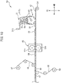
- FIG. 10 is a schematic view showing a configuration example of a manufacturing apparatus 50 of manufacturing the absorbent article 1 according to the embodiment.
- FIGS. 11(a) to 11(c) are schematic views showing the state in which the absorbent material is supplied on a suction drum 52 of the manufacturing apparatus 50 in FIG. 10 .
- the manufacturing apparatus 50 includes a transport duct 51 and a suction drum 52.
- the transport duct 51 transports the absorbent material that includes an opened water-absorbent fibers 8a and superabsorbent polymer particles 8b to the suction drum 52.
- the transport duct 51 includes a transport duct nozzle 51S that discharges the superabsorbent polymer particles 8b from a discharge port 51Sp to the suction drum 52.
- the suction drum 52 is rotatable, and sucks the absorbent material in the transport duct 51 and laminates the absorbent material on a plurality of concave mold members 53 arranged with a certain space along the circumferential direction of the outer circumferential surface to form a first laminated body 61 which becomes the absorbent core 9 of the absorbent body 7 in the later process.
- the manufacturing apparatus 50 further includes an unwinding roll 54 for the core wrap continuous body.
- the unwinding roll 54 unwinds a long core wrap continuous bodies 62 toward the suction drum 52.
- the suction drum 52 places the first laminated body 61 on the outer circumferential surface of the suction drum on the core wrap continuous body 62.
- the first laminated body 61 placed on the core wrap continuous body 62 is covered with the core wrap continuous body 62 to form a second laminated body 63.
- the manufacturing apparatus 50 further includes a pressing device 55.
- the pressing device 55 includes a pair of press rolls 55a and 55b that apply pressure and compress the second laminated body 63 in the thickness direction (TD direction).
- a third laminated body 64 is formed by pressing the second laminated body 63.
- the first step of forming the first laminated body 61 that will ultimately constitute the absorbent core 9 of the absorbent body 7 is performed.
- the absorbent material which includes the water-absorbent fibers 8a and the superabsorbent polymer particles 8b is sucked by the suction drum 52 through the transport duct 51, and the absorbent material is laminated in the mold member 53 on the outer circumferential surface of the suction drum 52 to form the first laminated body 61.
- the mold member 53 includes four pairs of protruding portions (in FIG. 11 , only 53a and 53b are shown) having a quadrangular cross section which extend in the circumferential direction of the suction drum 52 in a bottom portion 53c.
- each of the protruding portions 53a and 53b has a rectangular shape.
- These protruding portions 53a and 53b are arranged at positions adapted to the positions of the main groove portions 19 of the absorbent body 7 so as to have the shape and the width in the longitudinal direction adapted to the shape and the width in the longitudinal direction of the main groove portions 19.
- FIG. 11(a) shows the state in which the absorbent material is supplied on the suction drum 52 in the first region (for example, the first 1/5 of the entire region) of the region in which the absorbent material is supplied in the transport duct 51.
- This region is a region controlled so that the superabsorbent polymer particles 8b discharged from the discharge port 51Sp are supplied by a small amount or almost no amount of the superabsorbent polymer particles is supplied and the water-absorbent fibers 8a are supplied by a predetermined amount. Therefore, the water-absorbent fibers 8a are mainly supplied to and laminated on the bottom portion 53c of the mold member 53 of the suction drum 52.
- FIG. 11(b) shows the state in which the absorbent material is supplied on the suction drum 52 in an intermediate region (for example, 1/5 of the middle area of the entire region) of the region in which the absorbent material is supplied in the transport duct 51.
- This region is a region controlled so that the superabsorbent polymer particles 8b discharged from the discharge port 51Sp are supplied by another predetermined amount (more than the "small amount" of (a)) and the water-absorbent fibers 8a are supplied by a predetermined amount.
- FIG. 11(c) shows the state in which the absorbent material is supplied on the suction drum 52 in the last region (for example, the last 1/5 of the entire region) of the region in which the absorbent material is supplied in the transport duct 51.
- This region is a region controlled so that of the superabsorbent polymer particles 8b discharged from the discharge port 51Sp are supplied by small amount or another predetermined amount and the water-absorbent fibers 8a are supplied by a predetermined amount. Therefore, the superabsorbent polymer particles 8b and the water-absorbent fibers 8a are supplied and laminated on the upper part of the bottom portions 53c and the protruding portions 53a and 53b of the mold member 53 of the suction drum 52.
- the rotated suction drum 52 transfers the first laminated body 61 in the mold member 53 onto the core wrap continuous body 62 (coated with an adhesive) that is unwound from the unwinding roll 54 for the core wrap continuous body and is moved in the MD direction.
- the core wrap continuous body 62 is folded along the outer circumferential surface of the first laminated body 61 in the CD direction orthogonal to the MD direction with folding means (not shown), and the core wrap continuous body 62 is covered with the first laminated body 61 by being wound to form the long second laminated body 63.
- the second laminated body 63 is passed between the pair of press rolls 55a and 55b of the pressing device 55 to compress the second laminated body 63 in the TD direction.
- the third laminated body 64 is formed.
- the liquid-permeable continuous body 66 which is unwound from the unwinding roll 57 for the liquid-permeable continuous body is laminated on the upper surface of the third laminated body 64 with an adhesive agent such as a hot-melt adhesive agent to form the long fourth laminated body 65.
- the liquid-impermeable sheet continuous body 68 which is unwound from the unwinding roll 58 for the liquid-impermeable sheet continuous body is joined to the lower surface of the fourth laminated body 65 with an adhesive such as a hot-melt adhesive to form the long fifth laminated body 67.
- the fifth laminated body 67 is cut into the shape of the absorbent article 1 by a cutting device. Due to that, the absorbent article 1 is completed.
- An absorbent core including pulp (average basis weight: 220 g/m 2 ) and the superabsorbent polymer particles (average basis weight: 230 g/m 2 ) and having a size of 350 mm x 120 mm (longitudinal direction ⁇ lateral direction) was manufactured according to the above manufacturing method.
- the absorbent body in the step of FIG. 11(a) , was substantially formed of only the water-absorbent fibers, and in the steps of FIG. 11(b) and FIG. 11(c) , the absorbent body was substantially uniformly formed of the water-absorbent fibers and the superabsorbent polymer particles.
- the amount of the water-absorbent fibers supplied to the step of FIG. 11(a) was set to be 7.5%, 15%, 22.5%, and 30% of the total amount of the supplied water-absorbent fibers.
- the basis weights generally corresponded to 17 g/m 2 , 33 g/m 2 , 50 g/m 2 , and 66 g/m 2 .
- the amount of the water-absorbent fibers supplied to the step of FIG. 11(a) was set to 0% and 50% of the total amount of the supplied water-absorbent fibers.
- the basis weight generally corresponded to 0, 110 g/m 2 .
- four main groove portions (width: 4 mm) were arranged in the first layer with a space of 18 mm.
- each of the absorbent cores was covered with two sheets of tissue (basis weight: 16 g/m 2 , 400 mm ⁇ 150 mm) as a core wrap with a hot-melt adhesive interposed therebetween.
- the thickness of the absorbent core was adjusted by pressing the absorbent core covered with two pieces of tissue with a hydraulic press machine.
- the absorbent bodies of Examples 1 to 4 were formed from the absorbent cores of Examples 1 to 4, and the absorbent bodies of Comparative Examples 1 and 2 were formed from the absorbent cores of Comparative Examples 1 and 2.
- a liquid-permeable sheet air-through nonwoven fabric
- a liquid-impermeable sheet polyethylene film
Landscapes
- Health & Medical Sciences (AREA)
- Epidemiology (AREA)
- Engineering & Computer Science (AREA)
- Biomedical Technology (AREA)
- Heart & Thoracic Surgery (AREA)
- Vascular Medicine (AREA)
- Life Sciences & Earth Sciences (AREA)
- Animal Behavior & Ethology (AREA)
- General Health & Medical Sciences (AREA)
- Public Health (AREA)
- Veterinary Medicine (AREA)
- Absorbent Articles And Supports Therefor (AREA)
Abstract
Description
- The present invention relates to an absorbent article.
- There are known absorbent articles that exhibit excellent absorption performance (for example, absorption rate, and liquid return suppression) even when the absorbent articles repeatedly absorb bodily fluids. For example,
Patent Literature 1 discloses an absorbent article including an absorbent core including superabsorbent polymer particles. In the absorbent article, the absorbent core is formed of a first layer on a non-skin facing surface side and a second layer on a skin facing surface side. The first layer includes a plurality of groove portions including a plurality of main groove portions that extend in a longitudinal direction and penetrate the first layer in a thickness direction, and a plurality of base portions that extend in the longitudinal direction, and each of the plurality of main groove portions and each of the plurality of base portions are arranged alternately in a lateral direction. The second layer includes a plurality of main groove portion corresponding portions and a plurality of base corresponding portions arranged at positions overlapping with the plurality of main groove portions and the plurality of base portions in the thickness direction, respectively. Both an average density of the superabsorbent polymer particles contained in each of the plurality of base portions and an average density of the superabsorbent polymer particles contained in each of the plurality of main groove portion corresponding portions are lower than an average density of the superabsorbent polymer particles contained in each of the plurality of base corresponding portions. - Patent Literature 1:
Japanese Unexamined Patent Publication No. 2018-872 - An absorbent article as described in
Patent Literature 1 includes a main groove portion and a base portion adjacent to the main groove portion in the first layer on the non-skin facing surface side. Therefore, the bodily fluid (for example: urine) that has reached the first layer through the second layer can be diffused in the main groove portion in the longitudinal direction, can penetrate into the base portion and diffuse in the lateral direction, and thus can be held in the base portion. Due to that, the entire absorbent core can be effectively used for absorption of the bodily fluid. Further, since the superabsorbent polymer particles are included in the base portion and swell by absorbing the bodily fluid, the shape of the main groove portion in the thickness direction can be maintained. Therefore, such an absorbent article has excellent absorption performance, for example, diffusibility of bodily fluid, absorption rate, and liquid return suppression, even when the absorbent article repeatedly absorbs the bodily fluid. - However, in such an absorbent article, as the number of times the absorbent article absorbs a bodily fluid increases, the degree of swelling of the superabsorbent polymer particles in the base portion becomes excessively large, and there is a risk that the swollen superabsorbent polymer particles may block the bodily fluid (blocking). In such a case, since the bodily fluid is less likely to penetrate into the base portion and diffuse into the base portion in the lateral direction, there is a risk that the bodily fluid may not be sufficiently absorbed by the absorbent core to cause the deterioration of the absorption performance of the absorbent article, for example, absorption rate, and liquid return suppression. Therefore, there is room for improvement in absorption performance in a case where a bodily fluid is repeatedly absorbed in an absorbent article, for example, absorption rate, and liquid return suppression.
- An object of the present invention is to provide an absorbent article capable of improving absorption performance, for example, absorption rate, and liquid return suppression in a case where a bodily fluid is repeatedly absorbed in the absorbent article.
- According to the present invention, there is provided an absorbent article having a longitudinal direction, a lateral direction, and a thickness direction, the absorbent article comprising: an absorbent core including superabsorbent polymer particles, wherein the absorbent core has a non-skin facing surface, and a skin facing surface, and is formed of a first layer on a non-skin facing surface side, and a second layer on a skin facing surface side, the first layer includes: a plurality of groove portions that include a plurality of main groove portion extending in the longitudinal direction and penetrating the first layer in the thickness direction, and a plurality of base portions that extend in the longitudinal direction, each of the plurality of main groove portions and each of the plurality of base portions are arranged alternately in the lateral direction, each of the plurality of base portions is formed of: a base inner side portion adjacent to the non-skin facing surface side of the second layer, and a base outer side portion adjacent to the non-skin facing surface side of the base inner side portion, and an average density of the superabsorbent polymer particles contained in the base outer side portion is lower than an average density of the superabsorbent polymer particles contained in the base inner side portion.
- According to the present invention, an absorbent article capable of improving absorption performance, for example, absorption rate, and liquid return suppression in a case where a bodily fluid is repeatedly absorbed in the absorbent article can be provided.
-
-
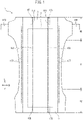
FIG. 1 is a plan view showing a configuration example of an absorbent article according to an embodiment. -
FIG. 2 is a plan view showing a configuration example of an absorbent body of the absorbent article according to the embodiment. -
FIG. 3 is a plan view showing a configuration example of an absorbent core of the absorbent article according to the embodiment. -
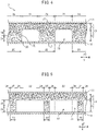
FIG. 4 is a cross-sectional view taken along a line IV-IV inFIG. 2 according to the embodiment. -
FIG. 5 is a cross-sectional view taken along a line V-V inFIG. 2 according to the embodiment. -
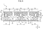
FIG. 6 is a schematic view showing flow of a bodily fluid in the cross section taken along the line IV-IV inFIG. 2 according to the embodiment. -
FIG. 7 is a cross-sectional view taken along the line IV-IV inFIG. 2 according to another embodiment. -
FIG. 8 is a cross-sectional view taken along the line V-V inFIG. 2 according to another embodiment. -
FIG. 9 is a schematic view showing flow of a bodily fluid in the cross section taken along the line IV-IV inFIG. 2 according to another embodiment. -
FIG. 10 is a schematic view showing a configuration example of a manufacturing apparatus used in a method of manufacturing the absorbent article according to the embodiment. -
FIG. 11 is a schematic view showing a state in which an absorbent material is supplied on a suction drum of a manufacturing apparatus. - The present embodiment relates to the following aspects.
- An absorbent article having a longitudinal direction, a lateral direction, and a thickness direction, the absorbent article comprising: an absorbent core including superabsorbent polymer particles, wherein the absorbent core has a non-skin facing surface, and a skin facing surface, and is formed of a first layer on a non-skin facing surface side, and a second layer on a skin facing surface side, the first layer includes: a plurality of groove portions that includes a plurality of main groove portions extending in the longitudinal direction and penetrating the first layer in the thickness direction, and a plurality of base portions that extend in the longitudinal direction, each of the plurality of main groove portions and each of the plurality of base portions are arranged alternately in the lateral direction, each of the plurality of base portions is formed of: a base inner side portion adjacent to the non-skin facing surface side of the second layer, and a base outer side portion adjacent to the non-skin facing surface side of the base inner side portion, and an average density of the superabsorbent polymer particles contained in the base outer side portion is lower than an average density of the superabsorbent polymer particles contained in the base inner side portion.
- Since the absorbent article includes the predetermined main groove portions and the predetermined base portions in the first layer, the bodily fluid that has permeated through the second layer is passed through the main groove portions and diffuses in the longitudinal direction while exuding into the base portions in the lateral direction. Here, in the present absorbent article, the average density of the superabsorbent polymer particles contained in the base outer side portion in the base portion of the first layer is lower than the average density of the superabsorbent polymer particles contained in the base inner side portion. Therefore, even in a case where the number of times the absorbent article absorbs the bodily fluid increases and the blocking due to the swelling of the superabsorbent polymer particles in the base inner side portion is likely to occur, the occurrence of blocking due to the swelling of the superabsorbent polymer particles in the base outer side portion can be suppressed. Due to that, the difficulty of the bodily fluid penetrating into the base portion and the difficulty of the bodily fluid diffusing in the base portion in the lateral direction can be suppressed. On the other hand, the collapse of the main groove portion in the thickness direction can be suppressed due to the swelling of the superabsorbent polymer particles in the base inner side portion. Therefore, as for the entire absorbent article, while the bodily fluid can be stably diffused in the main groove portion in the longitudinal direction, the bodily fluid can be stably diffused in the lateral direction. Accordingly, the entire absorbent core can be more effectively used for absorption of the bodily fluid, and the absorption performance, for example, absorption rate, and liquid return suppression in a case where the bodily fluid is repeatedly absorbed in the absorbent article can be enhanced.
- The absorbent article according to
aspect 1, wherein a thickness of the base outer side portion in the thickness direction is in a range of 20% to 80% of a thickness of each of the plurality of base portions in the thickness direction. - In the absorbent article, the thickness of the base outer side portion is in a range of 20% to 80% of the thickness of the base portion. Therefore, in a case where the absorbent article repeatedly absorbs bodily fluid, even when the blocking due to the swelling of the superabsorbent polymer particles in the base inner side portion is likely to occur, the occurrence of blocking due to the swelling of the superabsorbent polymer particles in the base outer side portion can be further suppressed. Therefore, the difficulty of the bodily fluid penetrating into the base portion and the difficulty of the bodily fluid diffusing in the base portion in the lateral direction can be more stably suppressed.
- The absorbent article according to
aspect - In the absorbent article, both the average density of the superabsorbent polymer particles contained in the base portion and the average density of the superabsorbent polymer particles contained in the main groove portion corresponding portion are lower than the average density of the superabsorbent polymer particles contained in the base corresponding portion. Therefore, when bodily fluid is absorbed, the bodily fluid can easily permeate into the main groove portion through the main groove portion corresponding portion, the water flow function of the main groove portion can be secured, and the bodily fluid that cannot be held in the base portion can be easily absorbed in the base corresponding portion. As described above, in the absorbent article, the bodily fluid can be absorbed by a bodily fluid absorption cycle in which the bodily fluid permeates from the main groove portion corresponding portion to the main groove portion (also referred to as "bodily fluid permeation action"), the permeated bodily fluid is drawn from the main groove portion to the adjacent base portion (also referred to as "bodily fluid drawing action"), and when the drawn bodily fluid cannot be held in the base portion, the bodily fluid is sucked up by the base corresponding portion (also referred to as "bodily fluid sucking action"). At this time, in the absorbent article, even when blocking in the base inner side portion is likely to occur, the occurrence of blocking due to the swelling of the superabsorbent polymer particles in the base outer side portion can be suppressed, and thus the bodily fluid absorption cycle can be stably maintained. Accordingly, even in a case where the bodily fluid is repeatedly absorbed in the absorbent article, the absorption performance can be enhanced.
- The absorbent article according to
aspect 3, wherein the average density of the superabsorbent polymer particles contained in each of the plurality of main groove portion corresponding portions is lower than the average density of the superabsorbent polymer particles contained in the base inner side portion of each of the plurality of base portions. - In the absorbent article according to claim 4, the average density of the superabsorbent polymer particles contained in the main groove portion corresponding portion is lower than the average density of the superabsorbent polymer particles contained in the base inner side portion of the base portion. Therefore, the swelling of the main groove portion corresponding portion can be suppressed, and the inhibition of the bodily fluid permeation action can be suppressed. Therefore, the absorption performance in a case where the bodily fluid is repeatedly absorbed in the absorbent article can be enhanced.
- The absorbent article according to aspect 4,
wherein the average density of the superabsorbent polymer particles contained in the base outer side portion of each of the plurality of base portions is lower than the average density of the superabsorbent polymer particles contained in each of the plurality of main groove portion corresponding portions. - In the absorbent article, the average density of the superabsorbent polymer particles contained in the base outer side portion of the base portion is lower than the average density of the superabsorbent polymer particles contained in the main groove portion corresponding portion. Therefore, the swelling of the base outer side portion can be suppressed, and the inhibition of the bodily fluid drawing action can be suppressed. Therefore, the absorption performance in a case where the bodily fluid is repeatedly absorbed in the absorbent article can be enhanced.
- The absorbent article according to any one of
aspects 1 to 5, wherein each of the plurality of groove portions further includes sub-groove portions that penetrate the first layer in the thickness direction and are present in communication with each of the plurality of main groove portions through a base end with a predetermined space in a direction crossing each of the plurality of main groove portions. - In the absorbent article, since the groove portion further includes a sub-groove portion crossing the main groove portion, the diffusion of the bodily fluid in the groove portion can be rapidly performed. Therefore, the entire absorbent core can be more effectively used for absorption of the bodily fluid, and thus the absorption performance in a case where the bodily fluid is repeatedly absorbed in the absorbent article can be enhanced.
- The absorbent article according to
aspect 6, wherein the second layer further includes: sub-groove portion corresponding portions arranged at positions overlapping with the sub-groove portions in the thickness direction, and an average density of the superabsorbent polymer particles contained in the sub-groove portion corresponding portion is lower than an average density of the superabsorbent polymer particles contained in each of the plurality of base corresponding portions. In the absorbent article, the average density of the superabsorbent polymer particles contained in the sub-groove portion corresponding portion is lower than the average density of the superabsorbent polymer particles contained in each of the base corresponding portions. Therefore, when bodily fluid is absorbed, the bodily fluid can easily permeate into the sub-groove portion through the sub-groove portion corresponding portion, and the water flow function of the sub-groove portion can be secured. In addition, the bodily fluid can be further absorbed by a bodily fluid absorption cycle in which while being diffused in a direction crossing the longitudinal direction along the sub-groove portion, the bodily fluid is drawn into the base portion and held therein, and the bodily fluid that cannot be held in the base portion is sucked up to the base corresponding portion. Therefore, the absorption performance in a case where the bodily fluid is repeatedly absorbed in the absorbent article can be enhanced. - The absorbent article according to any one of
aspects 1 to 7, wherein in each of the plurality of base portions, at one end portion and the other end portion in the lateral direction, and at a central part between the one end portion and the other end portion, an average density of the superabsorbent polymer particles contained in each of the one end portion and the other end portion is lower than an average density of the superabsorbent polymer particles contained in the central part. - In the absorbent article, in the lateral direction, the average density of the superabsorbent polymer particles contained in both end portions of the base portion is lower than the average density of the superabsorbent polymer particles contained in the central part. Therefore, the swelling of both end portions that come into contact with the main groove portion in the base portion can be suppressed, and the inhibition of the bodily fluid drawing action can be suppressed. Therefore, the absorption performance in a case where the bodily fluid is repeatedly absorbed in the absorbent article can be enhanced.
- Hereinafter, an absorbent article according to an embodiment will be described with reference to drawings.
- In the present specification, unless otherwise specified, "viewing an object (for example, an absorbent article, an absorbent body, or an absorbent core) placed on a horizontal plane in an unfolded state from above or below the object in the thickness direction" will be referred to as a "plan view". In a case where the object is an absorbent article, viewing the absorbent article in the thickness direction from a top-surface sheet side in an unfolded state may be simply referred to as a "plan view". In a case where the object is an absorbent core, viewing the absorbent article in the thickness direction from a non-skin facing surface side of the absorbent core in an unfolded state may be simply referred to as a "plan view".
- Various directions and the like used in the present specification are as follows, unless otherwise specified. The "longitudinal direction" refers to "a direction in which the length of a longitudinally long object in a plan view is long", the "lateral direction" refers to "a direction in which the length of the longitudinally long object in a plan view is short", and the "thickness direction" refers to "a direction vertical to the object placed on a horizontal plane in an unfolded state". The longitudinal direction, the lateral direction, and the thickness direction are in a relationship that is orthogonal to each other.
- In the present specification, unless otherwise specified, in the thickness direction of the absorbent article, a "proximal side relative to the skin surface of the wearer while the absorbent article is put on" is referred to as a "skin facing surface side", and a "distal side relative to the skin surface of the wearer while the absorbent article is put on" is referred to as a "non-skin facing surface side". In the present specification, the "skin facing surface side surface" and the "non-skin facing surface side surface" of various members (for example, a top-surface sheet, an absorbent body, and a back-surface sheet) that constitute the absorbent article are simply referred to as a "skin facing surface" and a "non-skin facing surface," respectively.
- In the present specification, the "main groove portion" means not only a groove portion that extends in a direction parallel to the longitudinal direction, but also a groove portion that extends along the longitudinal direction. An angle formed between the main groove portion and the longitudinal direction is preferably less than 45°, more preferably less than 30°, and even more preferably less than 15°. The main groove portion can extend linearly, or non-linearly, for example, in a curved shape. In the present specification, the width of the main groove portion means the length of the main groove portion in a direction orthogonal to a direction in which the main groove portion extends in an object portion.
- In the present specification, the "sub-groove portion" means not only a groove portion that extends in a direction parallel or substantially parallel to the lateral direction, but also a groove portion that extends in a direction other than the longitudinal direction. An angle formed between the sub-groove portion and the main groove portion (or the tangent line of the main groove portion) at a portion (base end) where the sub-groove portion communicates with the main groove portion is preferably 45° or more, more preferably 60° or more, and even more preferably 80° or more. The sub-groove portion can extend linearly, or non-linearly, for example, in a curved shape. In the present specification, the width of the sub-groove portion means the length of the sub-groove portion in a direction orthogonal to a direction in which the sub-groove portion extends in the object portion.
- In the present specification, the terms "front waist region," "back waist region," and "crotch region" are used in a case where the absorbent article is a disposable diaper, and the meanings are as follows. In a pull-on disposable diaper, the front waist region means a region interposed between a pair of joining portions at two lateral end portions that join a front body and a back body in the front body, and the back waist region means a region interposed between the pair of joining portions in the back body. The crotch region means a region between the front waist region and the back waist region. The crotch region also corresponds to a region interposed between the pair of leg openings. In a tape-type disposable diaper, the waist region and the crotch region are partitioned in a fixed state in which the tip ends of a pair of tape fasteners are fixed so as to be adjacent to a predetermined fixing region for the tape fastener. Specifically, the waist region is determined based on a pair of overlapping portions in which a waist forming member of the front body and a waist forming member of the back body overlap with each other in the absorbent article in the above fixed state. The front waist region means a region between the pair of overlapping portions in the front body of the absorbent article. Similarly, the back waist region means a region between the pair of overlapping portions in the back body of the absorbent article. The crotch region means a region between the front waist region and the back waist region.
- Hereinafter, an absorbent article according to an embodiment will be described.
FIGS. 1 to 6 are views showing configuration examples of anabsorbent article 1 according to the embodiment, specifically, a disposable diaper. Specifically,FIG. 1 is a plan view showing a configuration example of theabsorbent article 1 according to the embodiment.FIG. 2 is a plan view showing a configuration example of anabsorbent body 7 of theabsorbent article 1 according to the embodiment.FIG. 3 is a plan view showing a configuration example of anabsorbent core 9 of theabsorbent article 1 according to the embodiment.FIGS. 4 and 5 are a cross-sectional view taken along a line IV-IV inFIG. 2 , and a cross-sectional view taken along a line V-V, respectively.FIG. 6 is a schematic view showing the flow of bodily fluid in the cross section taken along the line IV-IV inFIG. 2 . - As shown in
FIG. 1 , theabsorbent article 1 includes a liquid-permeable sheet 3, a liquid-impermeable sheet 5, and anabsorbent body 7 arranged between the liquid-permeable sheet 3 and the liquid-impermeable sheet 5. As shown inFIGS. 2 and3 , theabsorbent body 7 has a longitudinal direction L, a lateral direction W, and a thickness direction T, and includes anabsorbent core 9 having askin facing surface 15 and anon-skin facing surface 17. In the present embodiment, theabsorbent core 9 includes acore wrap 11 formed of a tissue that covers theskin facing surface 15 and thenon-skin facing surface 17. It should be noted that, in the present embodiment, since the longitudinal direction, the lateral direction, and the thickness direction of theabsorbent article 1 are the same as those of theabsorbent body 7, the longitudinal direction L, the lateral direction W, and the thickness direction T are used as the directions of theabsorbent article 1. - In the present embodiment, as shown in
FIG. 1 , theabsorbent article 1 further includes a pair ofleakproof walls 101 includingelastic members 103, fixedportions 105 that fixe theleakproof walls 101 to the liquid-permeable sheet 3, anelastic members 107 around the leg portions, atape fasteners 109, and the like. It should be noted that these are well-known in the art and will not be described here. - As shown in
FIGS. 3 and4 , theabsorbent core 9 has thenon-skin facing surface 17 and theskin facing surface 15, and is formed of afirst layer 6 on the non-skin facing surface side and asecond layer 8 on the skin facing surface side. In addition, thefirst layer 6 includes a plurality ofgroove portions 18 including a plurality ofmain groove portions 19 that linearly extend in the longitudinal direction L and penetrate the first layer in the thickness direction T, and a plurality ofbase portions 20 that extend in the longitudinal direction L, and each of the plurality ofmain groove portions 19 and each of the plurality ofbase portions 20 are arranged alternately in the lateral direction W. Themain groove portion 19 is recessed from thenon-skin facing surface 17 toward theskin facing surface 15 in the thickness direction of theabsorbent core 9 and extends in the longitudinal direction L. Thebase portion 20 is formed of a baseinner side portion 36 adjacent to thenon-skin facing surface 17 side of thesecond layer 8, and a baseouter side portion 34 adjacent to thenon-skin facing surface 17 side of the baseinner side portion 36. - In the present embodiment, the
second layer 8 includes a plurality of main grooveportion corresponding portions 22 at positions that overlap with the plurality ofmain groove portions 19 in the thickness direction T, and a plurality ofbase corresponding portions 24 at positions that overlap with the plurality ofbase portions 20 in the thickness direction T. Further, in the present embodiment, as shown inFIGS. 3 and5 , thegroove portion 18 includes a plurality ofsub-groove portions 21. In addition, thesecond layer 8 includes a plurality of sub-grooveportion corresponding portions 26 at positions that overlap with the plurality ofsub-groove portions 21 in the thickness direction T. - In the present embodiment, the thickness of each of the
first layer 6 and thesecond layer 8 is preferably 0.1 to 5 mm, more preferably 0.5 to 4 mm, and even more preferably 1 to 3 mm. It should be noted that, in the present embodiment, the thickness of each of thefirst layer 6 and thesecond layer 8 can be measured in the following non-contact method using the laser displacement meter (for example, high-precision two-dimensional laser displacement meter LJ-G series (model: LJ-G030) manufactured by Keyence Corporation). Theabsorbent core 9 which is obtained by blowing a cold spray onto theabsorbent article 1 so as to peel off the liquid-permeable sheet 3, the liquid-impermeable sheet 5, and thecore wrap 11, is cut into a size of 100 mm × 100 mm, and is used as a sample. The sample is placed on a horizontal measurement table in a manner such that thenon-skin facing surface 17 having the plurality ofgroove portions 18 and the plurality ofbase portions 20 formed thereon faces upward, the displacement from the measurement table is measured by the laser displacement meter for fivedifferent base portions 20, and the average value of the five measurement values is set as Ax (mm). Similarly, the displacement from the measurement table is measured by the laser displacement meter for five different groove portions 18 (main groove portions 19), and the average value of the five measurement values is set as Ay (mm). The thickness of thesecond layer 8 is Ay (mm), and the thickness of thefirst layer 6 is calculated from a difference between Ax (mm) and Ay (mm). - The
absorbent core 9 includes water-absorbent fibers 30 and superabsorbent polymer particles (SAP) 32, and has a function of absorbing and holding the bodily fluid discharged to theabsorbent article 1. In the present embodiment, the average basis weight of the absorbent fibers in both thefirst layer 6 and thesecond layer 8 is preferably 50 to 250 g/m2, and more preferably 80 to 200 g/m2. In addition, the average basis weight of the superabsorbent polymer particles in thefirst layer 6 is smaller than the average basis weight of the superabsorbent polymer particles in thesecond layer 8. The average basis weight of the superabsorbent polymer particles in thefirst layer 6 is preferably 20 to 150 g/m2, and more preferably 30 to 100 g/m2, and the average basis weight of the superabsorbent polymer particles in thesecond layer 8 is preferably 50 to 350 g/m2, and more preferably 100 to 250 g/m2. A ratio of the average basis weight of the superabsorbent polymer particles in thefirst layer 6 to the average basis weight of the superabsorbent polymer particles in the entireabsorbent core 9 is preferably 20% to 45% and more preferably 25% to 35%. - As shown in
FIG. 4 , in theabsorbent core 9, the baseouter side portion 34 of thebase portion 20 and the baseinner side portion 36 of thebase portion 20 each have different average densities of the superabsorbent polymer particles. Specifically, the average density of the superabsorbent polymer particles contained in the baseouter side portion 34 is lower than the average density of the superabsorbent polymer particles contained in the baseinner side portion 36. Further, in the present embodiment, the average density of the superabsorbent polymer particles contained in the baseinner side portion 36 is equal to the average density of the superabsorbent polymer particles contained in thesecond layer 8 or lower than the average density of the superabsorbent polymer particles contained in thesecond layer 8. - As described above, in the present embodiment, the average densities of the superabsorbent polymer particles have a relationship of the base
outer side portion 34 < the baseinner side portion 36 ≤ thesecond layer 8. In such a configuration, for example, as shown inFIG. 6 , in the present embodiment, the bodily fluid moves in theabsorbent core 9 in substantially the following order. - (i) The bodily fluid that has reached the core wrap 11 passes through the second layer and then mainly moves to the
main groove portion 19 by gravity (arrow A). - (ii) The bodily fluid that has moved to the
main groove portion 19 diffuses in the longitudinal direction L while exuding into the baseouter side portion 34 and the baseinner side portion 36 of thebase portion 20 that are adjacent in the lateral direction W (arrows B1 and B2). - (iii) The bodily fluid that cannot be held by the
base portion 20 can be sucked up and held in the base corresponding portion 24 (arrow C). - Since the
absorbent article 1 includes the predeterminedmain groove portion 19 and thepredetermined base portion 20 in thefirst layer 6, the bodily fluid that has permeated through thesecond layer 8 is passed through themain groove portion 19 and diffuses in the longitudinal direction L while exuding into thebase portion 20 in the lateral direction W. Here, in theabsorbent article 1, the average density of the superabsorbent polymer particles contained in the baseouter side portion 34 of thebase portion 20 of thefirst layer 6 is lower than the average density of the superabsorbent polymer particles contained in the baseinner side portion 36. Therefore, even when the number of times theabsorbent article 1 absorbs the bodily fluid increases and the blocking due to the swelling of the superabsorbent polymer particles in the baseinner side portion 36 is likely to occur (the arrow B2 stops), the occurrence of blocking due to the swelling of the superabsorbent polymer particles in the baseouter side portion 34 can be suppressed. That is, regardless of the increase in the number of times of absorption of the bodily fluid, a state in which the bodily fluid moved to themain groove portion 19 easily continuously exudes into the baseouter side portion 34 can be maintained (arrow B1 continues). Due to that, the difficulty of the bodily fluid penetrating into thebase portion 20 and the difficulty of the bodily fluid diffusing in thebase portion 20 in the lateral direction W can be suppressed. On the other hand, the collapse of themain groove portion 19 in the thickness direction T can be suppressed due to swelling of the superabsorbent polymer particles in the baseinner side portion 36. Therefore, as for the entireabsorbent article 1, while the bodily fluid can be stably diffused in themain groove portion 19 in the longitudinal direction L, the bodily fluid can be stably diffused in the lateral direction W. Accordingly, the entireabsorbent core 9 can be more effectively used for absorption of the bodily fluid, and the absorption performance, for example, absorption rate, and liquid return suppression in a case where the bodily fluid is repeatedly absorbed in theabsorbent article 1 can be enhanced. - In the present embodiment, the average density of the superabsorbent polymer particles contained in the base
outer side portion 34 is preferably 0 to 0.15 g/cm3, more preferably 0 to 0.1 g/cm3, and even more preferably 0 to 0.08 g/cm3. In a case where the average density of the superabsorbent polymer particles contained in the baseouter side portion 34 is excessively high, the blocking due to the swelling of the superabsorbent polymer particles in the baseouter side portion 34 easily occurs, and the effect that the baseouter side portion 34 is less likely to be blocked than the baseinner side portion 36 is less likely to be exerted. - On the other hand, the average density of the superabsorbent polymer particles contained in the base
inner side portion 36 is preferably 0.02 to 0.35 g/cm3, more preferably 0.03 to 0.3 g/cm3, and even more preferably 0.04 to 0.25 g/cm3. In a case where the average density of the superabsorbent polymer particles contained in the baseinner side portion 36 is excessively low, the superabsorbent polymer particles in the baseinner side portion 36 are less likely to swell, and themain groove portion 19 easily collapses in the thickness direction T. In a case where the average density of the superabsorbent polymer particles contained in the baseinner side portion 36 is excessively high, the blocking due to the swelling of the superabsorbent polymer particles in the baseinner side portion 36 easily occur, and the diffusion of the bodily fluid in the lateral direction W is easily reduced. - At this time, a difference between the average density of the superabsorbent polymer particles contained in the base
inner side portion 36 and the average density of the superabsorbent polymer particles contained in the baseouter side portion 34 is preferably 0.01 to 0.35 g/cm3, more preferably 0.02 to 0.3 g/cm3, and even more preferably 0.03 to 0.25 g/cm3. When the difference is excessively small, blocking easily occurs in the entire base portion 20 (in a case where the average density is high), or themain groove portion 19 easily collapses in the thickness direction T (in a case where the average density is low). When the difference is excessively large, the blocking due to the swelling of the superabsorbent polymer particles in the baseinner side portion 36 easily occurs. - Further, the average density of the superabsorbent polymer particles contained in the
second layer 8 is preferably 0.03 to 0.4 g/cm3, more preferably 0.04 to 0.35 g/cm3, and even more preferably 0.05 to 0.3 g/cm3. In a case where the average density of the superabsorbent polymer particles contained in thesecond layer 8 is excessively low, the absorption amount of the bodily fluid in the entireabsorbent body 7 is easily decreased. In a case where the average density of the superabsorbent polymer particles contained in thesecond layer 8 is excessively high, the blocking due to the swelling of the superabsorbent polymer particles in thesecond layer 8 easily occurs, and the absorption amount of the bodily fluid in thebase portion 20 is easily decreased. It should be noted that, in the present embodiment, in thesecond layer 8, the average densities of the superabsorbent polymer particles in the main grooveportion corresponding portion 22, thebase corresponding portion 24, and the sub-grooveportion corresponding portion 26 are substantially the same. - A method of measuring the average density of the superabsorbent polymer particles is as follows. Five samples having a predetermined length and a predetermined width are cut out from the absorbent core 9 (for example, 4 mm × 4 mm), the superabsorbent polymer particles contained in each sample are selected, the total mass of the superabsorbent polymer particles contained in each sample is measured, and the measurement value is divided by the volume of the sample obtained by the thickness of the sample and the area of the sample to obtain the average value.
- In the present specification, in a case of evaluating the average density of the superabsorbent polymer particles in each of the portions of the base portion 20 (base
outer side portion 34, base inner side portion 36) and the second layer 8 (main grooveportion corresponding portion 22, base corresponding portion 24) in theabsorbent core 9, the following method may be employed. For example, theabsorbent article 1 serving as a sample is impregnated with liquid nitrogen so as to be frozen, and then, theabsorbent article 1 is cut with a razor in the thickness direction T, so as to obtain a cross section at the surface crossing the direction in which themain groove portion 19 extends. Next, the temperature of the sample is returned to room temperature, and a cross-sectional image with a magnification of 50 times is obtained by using an electron microscope (for example, VE7800 manufactured by Keyence Corporation). In the cross-sectional image, the degrees of the average density of the superabsorbent polymer particles at each of the portions of thebase portion 20, the main grooveportion corresponding portion 22, and thebase corresponding portion 24 is visually evaluated. It should be noted that, in a case of evaluating the degrees of the average density of the superabsorbent polymer particles in the sub-grooveportion corresponding portion 26 and the average density of the superabsorbent polymer particles in each of thebase portion 20 and thebase corresponding portion 24, which will be described later, evaluation can be performed using a cross-sectional image in the surface crossing the direction in which thesub-groove portion 25 extends in the same method as described above, instead of the above method. - In the present embodiment, the thickness of the base
outer side portion 34 in the thickness direction T is preferably in a range of 20% to 80% of the thickness of each of the plurality ofbase portions 20 in the thickness direction T, more preferably in a range of 30% to 70%, and even more preferably in a range of 35% to 65%. However, the thickness of thebase portion 20 in the thickness direction T can be referred to as the thickness of the first layer 6 (baseinner side portion 36 + base outer side portion 34) or the groove depth of themain groove portion 19. - In such an
absorbent article 1, the thickness of the baseouter side portion 34 is in a range of 20% to 80% of the thickness of the base portion. Therefore, even in a case where the blocking due to the swelling of the superabsorbent polymer particles in the baseinner side portion 36 is likely to occur when theabsorbent article 1 repeatedly absorbs the bodily fluid, the occurrence of the blocking due to the swelling of the superabsorbent polymer particles of the baseouter side portion 34 can be further suppressed. That is, even when the bodily fluid is less likely to penetrate into thebase portion 20 through the baseinner side portion 36, the bodily fluid can be allowed to penetrate into thebase portion 20 through the baseouter side portion 34. Therefore, the difficulty of the bodily fluid penetrating into thebase portion 20 and the difficulty of the bodily fluid diffusing in thebase portion 20 in the lateral direction W can be more stably suppressed. - It should be noted that, in a case where a ratio of the thickness of the base
inner side portion 36 to the thickness of thebase portion 20 is excessively low, the amount of the superabsorbent polymer particles that swell in the baseinner side portion 36 is decreased, and themain groove portion 19 easily collapses in the thickness direction T. On the other hand, in a case where the ratio of the thickness of the baseinner side portion 36 to the thickness of thebase portion 20 is excessively high, when the bodily fluid is less likely to penetrate into thebase portion 20 through the baseinner side portion 36 due to the swelling of the superabsorbent polymer particles, the bodily fluid that penetrates into thebase portion 20 through the baseouter side portion 34 is reduced, and the absorption amount of the bodily fluid is easily reduced in thebase portion 20. - In the present specification, a method of measuring and calculating the relative thicknesses of the base
outer side portion 34 and the baseinner side portion 36 is as follows. - A sample piece including a measurement target portion is prepared from the
absorbent article 1. The sample piece is anabsorbent body 7 that includes theabsorbent core 9 and thecore wrap 11 and from which the elastic member, the liquid-permeable sheet 3, the liquid-impermeable sheet 5, and the like of theabsorbent article 1 are removed, and is a test piece for X-ray cross section observation obtained by cutting theabsorbent body 7 in the lateral direction to have a width of 15 mm in a plan view. It should be noted that in a case where theabsorbent body 7, the liquid-permeable sheet 3, and the liquid-impermeable sheet 5 are integrally formed, and in a case where the liquid-permeable sheet 3 and the liquid-impermeable sheet 5 cannot be removed without destroying the shape of theabsorbent body 7, the sample piece is a test piece for X-ray cross section observation having theabsorbent body 7 that includes theabsorbent core 9 and thecore wrap 11, the liquid-permeable sheet 3, and the liquid-impermeable sheet 5 of theabsorbent article 1 from which the elastic member is removed, and obtained by cutting theabsorbent body 7 in the lateral direction to a width of 15 mm in a plan view. Next, by using the following X-ray photographing apparatus and image processing software, a cross section of the sample piece is photographed to obtain an internal cross-sectional photograph including the thickness direction T thereof in BMP format. Then, the obtained X-ray fluoroscopic image having a field size of 30 × 20 mm is tiled in the lateral direction of theabsorbent body 7, and the thickness of theabsorbent body 7, the thickness of the baseouter side portion 34, and the groove depth of themain groove portion 19 are calculated using the number of pixels of the composite image analysis software. Thereafter, assuming that the total thickness of theabsorbent body 7 is 100, the ratio of the groove depth of themain groove portion 19 and the thickness of the baseouter side portion 34 is calculated. Measurement and photographing apparatus: X-ray fluoroscopy apparatus: FLEX-M863 (manufactured by Beam Sense Co., Ltd.) - Photographing conditions: tube voltage 35 kV, tube current 100 µA, pixel size: 20 × 20 µm Number of pixels: 1500 × 1000 pixels, Resolution: 2 µm (geometric magnification: 10)
- Image connection software/image measurement software: UN Analyzer (manufactured by Unique Co., Ltd.)
- From the internal cross-sectional photograph of the BMP format obtained in (1), the number of pixels corresponding to the total thickness of the
absorbent body 7, the thickness of the baseouter side portion 34, and the groove depth of themain groove portion 19 are read. The total thickness of theabsorbent body 7, the groove depth of themain groove portion 19, the thickness of the baseouter side portion 34, the thickness of the base inner side portion 36 (the groove depth of the main groove portion 19 - the thickness of the base outer side portion 34), and the thickness of the second layer 8 (the total thickness of the absorbent body 7 - the groove depth of the main groove portion 19) are calculated. Thereafter, assuming that the total thickness of theabsorbent body 7 is 100, the ratios of the groove depth of themain groove portion 19, the thickness of the baseouter side portion 34, the thickness of the baseinner side portion 36, and the thickness of thesecond layer 8 are calculated as the relative thickness and depth. - In a preferable aspect of the present embodiment, in the
base portion 20, at one end portion and the other end portion, and at the central part between the one end portion and the other end portion in the lateral direction W, the average density of the superabsorbent polymer particles contained in each of the one end portion and the other end portion is lower than the average density of the superabsorbent polymer particles contained in the central part. However, the end portion refers to a range of 1/5 of the length of thebase portion 20 in the lateral direction W from the end edge of thebase portion 20 in the lateral direction W. In such anabsorbent article 1, the swelling of two end portions that come into contact with themain groove portions 19 in the base portion can be suppressed, and the inhibition of the bodily fluid drawing action can be suppressed. Therefore, the absorption performance in a case where the bodily fluid is repeatedly absorbed in theabsorbent article 1 can be enhanced. - Hereinafter, an absorbent article according to an embodiment will be described.
- In the present embodiment, differences from the first embodiment will be mainly described.
FIGS. 7 to 9 are view showing configuration examples of theabsorbent article 1 according to the embodiment, specifically, a disposable diaper. Specifically,FIGS. 7 and 8 are a cross-sectional view taken along the line IV-IV inFIG. 2 and a cross-sectional view taken along the line V-V, respectively.FIG. 9 is a schematic view showing the flow of the bodily fluid in the cross-section taken along the line IV-IV inFIG. 2 . - As shown in
FIG. 7 , theabsorbent core 9 has different average densities of the superabsorbent polymer particles in the baseouter side portion 34 and the baseinner side portion 36 of thebase portion 20, the main grooveportion corresponding portion 22, and thebase corresponding portion 24. Specifically, the average density of the superabsorbent polymer particles contained in the base portion 20 (the baseouter side portion 34 and the base inner side portion 36) and the average density of the superabsorbent polymer particles contained in the main grooveportion corresponding portion 22 are lower than the average density of the superabsorbent polymer particles contained in thebase corresponding portion 24. - In the present embodiment, the average densities of the superabsorbent polymer particles contained in the base
outer side portion 34 and the baseinner side portion 36 of thebase portion 20 are as described in the first embodiment. The average density of the superabsorbent polymer particles contained in the main grooveportion corresponding portion 22 are preferably 0 to 0.25 g/cm3, more preferably 0 to 0.2 g/cm3, and even more preferably 0 to 0.15 g/cm3. On the other hand, the average density of the superabsorbent polymer particles contained in thebase corresponding portion 24 is preferably 0.1 to 0.45 g/cm3, more preferably 0.1 to 0.4 g/cm3, and even more preferably 0.1 to 0.35 g/cm3. - As described above, in the present embodiment, the average densities of the superabsorbent polymer particles have a relationship of the base portion 20 (base
outer side portion 34 and base inner side portion 36) and the main grooveportion corresponding portion 22 < thebase corresponding portion 24. In such a configuration, in the present embodiment, as shown inFIG. 9 , the bodily fluid moves in theabsorbent core 9 in substantially the following order. - (i) The bodily fluid that has reached the
core wrap 11 permeates into the main grooveportion corresponding portion 22 in thesecond layer 8, where the average density of the superabsorbent polymer particles is relatively low and the bodily fluid easily penetrates into the main grooveportion corresponding portion 22, and further moves to themain groove portion 19 by gravity (arrow A). - (ii) The bodily fluid that has moved to the
main groove portion 19 diffuses in the longitudinal direction L while exuding into the baseouter side portion 34 and the baseinner side portion 36 of thebase portion 20 that are adjacent in the lateral direction W (arrows B1 and B2). - (iii) The bodily fluid that cannot be held in the
base portion 20 is sucked up by thebase corresponding portion 24 having the highest average density of the superabsorbent polymer particles in theabsorbent core 9, and is held therein (arrow C). - In the
absorbent article 1, both the average density of the superabsorbent polymer particles contained in thebase portion 20 and the average density of the superabsorbent polymer particles contained in the main grooveportion corresponding portion 22 are lower than the average density of the superabsorbent polymer particles contained in thebase corresponding portion 24. Therefore, when the bodily fluid is absorbed, the bodily fluid can easily permeate into themain groove portion 19 through the main grooveportion corresponding portion 22, the water flow function of themain groove portion 19 can be secured, and the bodily fluid that cannot be held in thebase portion 20 can be easily absorbed in thebase corresponding portion 24. As described above, in theabsorbent article 1, the bodily fluid can be absorbed by a bodily fluid absorption cycle in which the bodily fluid permeates from the main grooveportion corresponding portion 22 to the main groove portion 19 (also referred to as "bodily fluid permeation action"), the permeated bodily fluid is drawn from themain groove portion 19 to the adjacent base portion 20 (also referred to as "bodily fluid drawing action"), and when the drawn bodily fluid cannot be held in thebase portion 20, the bodily fluid is sucked up by the base corresponding portion 24 (also referred to as "bodily fluid sucking action"). At this time, in theabsorbent article 1, even when blocking in the baseinner side portion 36 is likely to occur, the occurrence of blocking due to the swelling of the superabsorbent polymer particles in the baseouter side portion 34 can be suppressed, and thus the bodily fluid absorption cycle can be stably maintained. Therefore, the absorption performance in a case where the bodily fluid is repeatedly absorbed in the presentabsorbent article 1 can be enhanced. - In a preferable aspect of the present embodiment, the average density of the superabsorbent polymer particles contained in the main groove
portion corresponding portion 22 is lower than the average density of the superabsorbent polymer particles contained in the baseinner side portion 36 of thebase portion 20. In such anabsorbent article 1, the swelling of the main grooveportion corresponding portion 22 can be suppressed, and the inhibition of the bodily fluid permeation action can be suppressed. Therefore, the absorption performance in a case where the bodily fluid is repeatedly absorbed in theabsorbent article 1 can be enhanced. - In a preferable aspect of the present embodiment, the average density of the superabsorbent polymer particles contained in the base
outer side portion 34 of thebase portion 20 is lower than the average density of the superabsorbent polymer particles contained in the main grooveportion corresponding portion 22. In such anabsorbent article 1, the swelling of the baseouter side portion 34 can be suppressed and the inhibition of the bodily fluid drawing action can be suppressed. Therefore, the absorption performance in a case where the bodily fluid is repeatedly absorbed in theabsorbent article 1 can be enhanced. - In a preferable aspect of the present embodiment, the average density of the superabsorbent polymer particles contained in the sub-groove
portion corresponding portion 26 is lower than the average density of the superabsorbent polymer particles contained in thebase corresponding portion 24. At this time, the average density of the superabsorbent polymer particles contained in the sub-grooveportion corresponding portion 26 is approximately the same as the average density of the superabsorbent polymer particles contained in the main grooveportion corresponding portion 22. In such anabsorbent article 1, when the bodily fluid is absorbed, the bodily fluid can easily permeate into thesub-groove portion 21 through the sub-grooveportion corresponding portion 26, and the water flow function of thesub-groove portion 21 can be secured. In addition, the bodily fluid can be further absorbed by a bodily fluid absorption cycle in which while being diffused in a direction crossing the longitudinal direction L along thesub-groove portion 21, the bodily fluid is drawn into the base portion 20 (baseouter side portion 34, base inner side portion 36) and held therein, and the bodily fluid that cannot be held in thebase portion 20 is sucked up to thebase corresponding portion 24. Therefore, the absorption performance in a case where the bodily fluid is repeatedly absorbed in theabsorbent article 1 can be enhanced. - In a preferable aspect of the first and second embodiments, as shown in
FIG. 2 , theabsorbent body 7 is partitioned into a right region RA and a left region LA by a longitudinal central axis line VL that bisects theabsorbent body 7 in the lateral direction W. Further, theabsorbent body 7 includes twomain groove portions 19 in each of the right region RA and the left region LA. - In the first and second embodiment, as shown in
FIG. 1 , theabsorbent article 1 is partitioned in the longitudinal direction L into three regions: a front waist region FW, a back waist region RW, and a crotch region C between the front waist region FW and the back waist region RW. Further, theabsorbent body 7 is arranged across the three regions, and thesub-groove portions 21 are provided in all of the three regions. - In the first and second embodiments, the
groove portion 18 is not limited to the configuration in which themain groove portion 19 linearly extends along the longitudinal direction L and thesub-groove portion 21 is orthogonal to themain groove portion 19. For example, thegroove portion 18 may include only themain groove portion 19 and may not include thesub-groove portion 21. Further, themain groove portion 19 may not extend across the front waist region FW, the crotch region C, and the back waist region RW in the longitudinal direction L of theabsorbent core 9, and may be arranged only in the region of the crotch region C, for example. Further, each of the plurality ofmain groove portions 19 may be arranged so as to extend in a zigzag shape along the longitudinal direction L in a plan view, and to alternately form a broad base portion having a relatively large width and a narrow base portion having a relatively narrow width with themain groove portions 19 which are adjacent to each other in the longitudinal direction L. Alternatively, each of the plurality of main groove portions may extend in a zigzag shape along the longitudinal direction L in a plan view, and the adjacentmain groove portions 19 may be arranged in a manner such that the width of thebase portion 20 becomes constant, or each of the plurality ofmain groove portions 19 may extend in a wavy shape in a plan view. - In the first and second embodiments, as shown in
FIG. 4 , thecore wrap 11 that covers thenon-skin facing surface 17 of theabsorbent core 9 may be arranged so as to protrude toward theskin facing surface 15 side although not to come into contact with the main grooveportion corresponding portion 22 in themain groove portion 19. In such a case, the diffusibility of the bodily fluid in the longitudinal direction L and the lateral direction W in themain groove portion 19 can be enhanced. Alternatively, thecore wrap 11 that covers thenon-skin facing surface 17 of theabsorbent core 9 may come into contact with the main grooveportion corresponding portion 22, or may be partially or continuously joined to the main grooveportion corresponding portion 22 with a compressed portion or a joining portion. As described above, themain groove portion 19 is formed by intermittently compressing or joining a part of the width of the main grooveportion corresponding portion 22 along themain groove portion 19, and thus the wearer is less likely to feel the hardness of the compressed portion or the joining portion. In addition, since themain groove portion 19 is formed by continuously compressing or joining a part of the width of the main grooveportion corresponding portion 22 in the longitudinal direction L, theabsorbent article 1 is easily folded with respect to themain groove portion 19, and exhibits excellent fitting property. - In the first and second embodiment, in the
absorbent article 1, themain groove portion 19 has a width of preferably 0.5 to 3.0 times, more preferably 0.8 to 2.5 times, and even more preferably 1.0 to 2.0 times as much of the thickness of theabsorbent body 7. When the width of themain groove portion 19 is within the above range, themain groove portion 19 easily maintains its water flow function after theabsorbent article 1 absorbs the bodily fluid. - In the present specification, unless otherwise specified, the thickness (mm) of an object (for example, an absorbent body or an absorbent core) is measured as follows. FS-60DS [the measurement surface: 44 mm (in diameter), the measurement pressure: 3 g/cm2] manufactured by Daiei Kagaku Seiki MFG, Co., Ltd. is prepared, five different portions of the object are applied with pressure under the standard condition (the temperature: 23±2°C, the relative humidity: 50±5%), the thickness at each of the portions 10 seconds after being applied with pressure is measured, and the average value of the 5 measurement values is used as the thickness of the object.
- In the first and second embodiments, a space between the
sub-groove portions 21 that are adjacent to each other in the lateral direction W is preferably 10% to 80%, and more preferably 20% to 60% of the space between the plurality ofmain groove portions 19 that are adjacent to each other in the lateral direction W. As described above, when thesub-groove portions 21 have a predetermined space, a predetermined width can be secured in thebase portion 20 present between thesub-groove portions 21, the bodily fluid absorbed in thebase portion 20 through thesub-groove portions 21 is easily diffused in the longitudinal direction L, and even when the bodily fluid is repeatedly absorbed, theabsorbent article 1 has excellent diffusibility, absorption rate, and liquid return suppression. - In a case of manufacturing the
absorbent article 1 having the configuration described in the above embodiment, there is no limitation on the manufacturing method. However, for example, the following method can be used. Incidentally, in the present specification, the "the machine direction of a material or a product" is referred to as "the MD direction", "the direction orthogonal to the MD direction on a horizontal plane" (that is, the width direction of the manufacturing line) is referred to as "the CD direction", and "the direction orthogonal to the MD direction and the CD direction" (that is, the vertical direction of the manufacturing line) is referred to as "the TD direction". -
FIG. 10 is a schematic view showing a configuration example of amanufacturing apparatus 50 of manufacturing theabsorbent article 1 according to the embodiment. In addition,FIGS. 11(a) to 11(c) are schematic views showing the state in which the absorbent material is supplied on asuction drum 52 of themanufacturing apparatus 50 inFIG. 10 . - The
manufacturing apparatus 50 includes atransport duct 51 and asuction drum 52. Thetransport duct 51 transports the absorbent material that includes an opened water-absorbent fibers 8a andsuperabsorbent polymer particles 8b to thesuction drum 52. Thetransport duct 51 includes atransport duct nozzle 51S that discharges thesuperabsorbent polymer particles 8b from a discharge port 51Sp to thesuction drum 52. Thesuction drum 52 is rotatable, and sucks the absorbent material in thetransport duct 51 and laminates the absorbent material on a plurality ofconcave mold members 53 arranged with a certain space along the circumferential direction of the outer circumferential surface to form a firstlaminated body 61 which becomes theabsorbent core 9 of theabsorbent body 7 in the later process. - The
manufacturing apparatus 50 further includes an unwindingroll 54 for the core wrap continuous body. The unwindingroll 54 unwinds a long core wrapcontinuous bodies 62 toward thesuction drum 52. Thesuction drum 52 places the firstlaminated body 61 on the outer circumferential surface of the suction drum on the core wrapcontinuous body 62. The firstlaminated body 61 placed on the core wrapcontinuous body 62 is covered with the core wrapcontinuous body 62 to form a secondlaminated body 63. Themanufacturing apparatus 50 further includes apressing device 55. Thepressing device 55 includes a pair of press rolls 55a and 55b that apply pressure and compress the secondlaminated body 63 in the thickness direction (TD direction). A thirdlaminated body 64 is formed by pressing the secondlaminated body 63. Themanufacturing apparatus 50 further includes an unwindingroll 57 for a liquid-permeable sheet continuous body. The unwindingroll 57 unwinds and laminates a long liquid-permeable sheetcontinuous body 66 that serves as the liquid-permeable sheet 3 on one surface (in the case ofFIG. 10 , the upper surface) of the thirdlaminated body 64. The liquid-permeable-sheetcontinuous body 66 is laminated on the thirdlaminated body 64 to form a fourthlaminated body 65. Themanufacturing apparatus 50 further includes an unwindingroll 58 for a liquid-impermeable sheet continuous body. The unwindingroll 58 unwinds and joins a long liquid-impermeable sheetcontinuous body 68 that serves as the liquid-impermeable sheet 5 to the surface (in the case ofFIG. 10 , the lower surface) of the fourthlaminated body 65 opposite to the liquid-permeable sheetcontinuous body 66. The liquid-impermeable sheetcontinuous body 68 is laminated on the fourthlaminated body 65 to form a fifthlaminated body 67. - It should be noted that the
manufacturing apparatus 50 includes a device (not shown) that cuts the fifthlaminated body 67 into the shape of theabsorbent article 1 as a product so as to be a singleabsorbent article 1, and each of the devices that compressesleakproof walls 101 and thetape fasteners 109 onto the fifthlaminated body 67 on the downstream side in the MD direction with respect to the unwindingroll 58. However, since these devices are ordinary devices known in this technical field, the detailed explanation is omitted. - In a case where the
absorbent article 1 is manufactured by using themanufacturing apparatus 50 described above, the following steps are performed. That is, the following steps are sequentially performed: a first step of forming the firstlaminated body 61; a second step of covering the firstlaminated body 61 with the core wrapcontinuous body 62 to form the secondlaminated body 63; and a third step of compressing the secondlaminated body 63 in the TD direction with thepressing device 55 to form the thirdlaminated body 64. Further, a fourth step of laminating the liquid-permeable sheetcontinuous body 66 on the thirdlaminated body 64 to form the fourthlaminated body 65, and a fifth step of joining the liquid-impermeable sheetcontinuous body 68 to the fourthlaminated body 65 to form the fifthlaminated body 67 are sequentially performed. - First, the first step of forming the first
laminated body 61 that will ultimately constitute theabsorbent core 9 of theabsorbent body 7 is performed. In the first step, the absorbent material which includes the water-absorbent fibers 8a and thesuperabsorbent polymer particles 8b is sucked by thesuction drum 52 through thetransport duct 51, and the absorbent material is laminated in themold member 53 on the outer circumferential surface of thesuction drum 52 to form the firstlaminated body 61. - Here, the
mold member 53 includes four pairs of protruding portions (inFIG. 11 , only 53a and 53b are shown) having a quadrangular cross section which extend in the circumferential direction of thesuction drum 52 in abottom portion 53c. Specifically, each of the protrudingportions portions main groove portions 19 of theabsorbent body 7 so as to have the shape and the width in the longitudinal direction adapted to the shape and the width in the longitudinal direction of themain groove portions 19. -
FIG. 11(a) shows the state in which the absorbent material is supplied on thesuction drum 52 in the first region (for example, the first 1/5 of the entire region) of the region in which the absorbent material is supplied in thetransport duct 51. This region is a region controlled so that thesuperabsorbent polymer particles 8b discharged from the discharge port 51Sp are supplied by a small amount or almost no amount of the superabsorbent polymer particles is supplied and the water-absorbent fibers 8a are supplied by a predetermined amount. Therefore, the water-absorbent fibers 8a are mainly supplied to and laminated on thebottom portion 53c of themold member 53 of thesuction drum 52. The total laminated thickness of thesuperabsorbent polymer particles 8b and the water-absorbent fibers 8a is smaller than the height of the protrudingportions outer side portions 34 are formed. -
FIG. 11(b) shows the state in which the absorbent material is supplied on thesuction drum 52 in an intermediate region (for example, 1/5 of the middle area of the entire region) of the region in which the absorbent material is supplied in thetransport duct 51. This region is a region controlled so that thesuperabsorbent polymer particles 8b discharged from the discharge port 51Sp are supplied by another predetermined amount (more than the "small amount" of (a)) and the water-absorbent fibers 8a are supplied by a predetermined amount. Therefore, thesuperabsorbent polymer particles 8b and the water-absorbent fibers 8a are supplied and laminated on the upper part of thebottom portions 53c and the protrudingportions mold member 53 on the outer circumferential surface of thesuction drum 52. The total laminate thickness of thesuperabsorbent polymer particles 8b and the water-absorbent fibers 8a is larger than the height of the protrudingportions inner side portions 36 and a part of thesecond layer 8 are further formed. -
FIG. 11(c) shows the state in which the absorbent material is supplied on thesuction drum 52 in the last region (for example, the last 1/5 of the entire region) of the region in which the absorbent material is supplied in thetransport duct 51. This region is a region controlled so that of thesuperabsorbent polymer particles 8b discharged from the discharge port 51Sp are supplied by small amount or another predetermined amount and the water-absorbent fibers 8a are supplied by a predetermined amount. Therefore, thesuperabsorbent polymer particles 8b and the water-absorbent fibers 8a are supplied and laminated on the upper part of thebottom portions 53c and the protrudingportions mold member 53 of thesuction drum 52. The total laminate thickness of thesuperabsorbent polymer particles 8b and the water-absorbent fibers 8a is larger than the height of the protrudingportions second layer 8 is further formed, and finally theabsorbent core 9 is formed. - It should be noted that, in a case where it is desired to decrease the average density of the superabsorbent polymer particles in the main groove portion corresponding portion 22 (or the sub-groove portion corresponding portion 26) of the
second layer 8 in the second embodiment, the manufacturing method of Patent Literature 1 (Japanese Unexamined Patent Publication No. 2018-872 superabsorbent polymer particles 8b in a relatively large amount is further arranged in thetransport duct 51 and thesecond layer 8 is formed, the absorbent material is supplied from the transport duct nozzle 51H present at a lower position than thetransport duct nozzle 51S. In such a case, since thesuperabsorbent polymer particles 8b are contained in a large discharge amount, when thesuperabsorbent polymer particles 8b collide with the protrudingportions superabsorbent polymer particles 8b are easily bounced back, and due to that, in the firstlaminated body 61, there is a portion in which the average density of thesuperabsorbent polymer particles 8b is low in the portions on the protrudingportions portions - In the second step, the rotated
suction drum 52 transfers the firstlaminated body 61 in themold member 53 onto the core wrap continuous body 62 (coated with an adhesive) that is unwound from the unwindingroll 54 for the core wrap continuous body and is moved in the MD direction. Then, the core wrapcontinuous body 62 is folded along the outer circumferential surface of the firstlaminated body 61 in the CD direction orthogonal to the MD direction with folding means (not shown), and the core wrapcontinuous body 62 is covered with the firstlaminated body 61 by being wound to form the long secondlaminated body 63. Next, in the third step, the secondlaminated body 63 is passed between the pair of press rolls 55a and 55b of thepressing device 55 to compress the secondlaminated body 63 in the TD direction. At this time, the thirdlaminated body 64 is formed. Next, in the fourth step, the liquid-permeablecontinuous body 66 which is unwound from the unwindingroll 57 for the liquid-permeable continuous body is laminated on the upper surface of the thirdlaminated body 64 with an adhesive agent such as a hot-melt adhesive agent to form the long fourthlaminated body 65. Next, in the fifth step, the liquid-impermeable sheetcontinuous body 68 which is unwound from the unwindingroll 58 for the liquid-impermeable sheet continuous body is joined to the lower surface of the fourthlaminated body 65 with an adhesive such as a hot-melt adhesive to form the long fifthlaminated body 67. After the fifth step is completed, the fifthlaminated body 67 is cut into the shape of theabsorbent article 1 by a cutting device. Due to that, theabsorbent article 1 is completed. - In the above manufacturing method, an aspect has been described in which the
mold member 53 is provided with the protrudingportions main groove portion 19. However, as a method of manufacturing the absorbent article, themold member 53 may be provided with the protruding portions for forming thesub-groove portions 21. Further, each step can be appropriately changed without departing from the spirit of the present disclosure. - Hereinafter, the present invention will be described by showing examples, but the present invention is not limited to these examples.
- An absorbent core including pulp (average basis weight: 220 g/m2) and the superabsorbent polymer particles (average basis weight: 230 g/m2) and having a size of 350 mm x 120 mm (longitudinal direction × lateral direction) was manufactured according to the above manufacturing method. However, in the above manufacturing method, in the step of
FIG. 11(a) , the absorbent body was substantially formed of only the water-absorbent fibers, and in the steps ofFIG. 11(b) and FIG. 11(c) , the absorbent body was substantially uniformly formed of the water-absorbent fibers and the superabsorbent polymer particles. In the absorbent cores of Examples 1 to 4, the amount of the water-absorbent fibers supplied to the step ofFIG. 11(a) was set to be 7.5%, 15%, 22.5%, and 30% of the total amount of the supplied water-absorbent fibers. The basis weights generally corresponded to 17 g/m2, 33 g/m2, 50 g/m2, and 66 g/m2. On the other hand, in the absorbent cores of Comparative Examples 1 and 2, the amount of the water-absorbent fibers supplied to the step ofFIG. 11(a) was set to 0% and 50% of the total amount of the supplied water-absorbent fibers. The basis weight generally corresponded to 0, 110 g/m2. In the absorbent core, four main groove portions (width: 4 mm) were arranged in the first layer with a space of 18 mm. - Next, each of the absorbent cores was covered with two sheets of tissue (basis weight: 16 g/m 2, 400 mm × 150 mm) as a core wrap with a hot-melt adhesive interposed therebetween. The thickness of the absorbent core was adjusted by pressing the absorbent core covered with two pieces of tissue with a hydraulic press machine. Thus, the absorbent bodies of Examples 1 to 4 were formed from the absorbent cores of Examples 1 to 4, and the absorbent bodies of Comparative Examples 1 and 2 were formed from the absorbent cores of Comparative Examples 1 and 2. Thereafter, a liquid-permeable sheet (air-through nonwoven fabric) was attached to the second layer side of each absorbent body, and a liquid-impermeable sheet (polyethylene film) was attached to the first layer side. Accordingly, simple absorbent articles of Examples 1 to 4 were formed from the absorbent bodies of Examples 1 to 4, and simple absorbent articles of Comparative Examples 1 and 2 were formed from the absorbent bodies of Comparative Examples 1 and 2.
- The absorbent articles of Examples 1 to 4 and the absorbent articles of Comparative Examples 1 and 2 were subjected to the following absorbent test, and the absorption rate and liquid return amount (rewet) were evaluated. The results of the evaluation are shown in Table 1.
-
- (1) The absorbent article is set in a U-shaped instrument having a substantially U-shaped side view. It should be noted that the absorbent article is set so that the central position of the absorbent body in the longitudinal direction matches the central part of the U-shaped instrument (the position at which the height is the lowest).
-
- (2) 80 mL of artificial urine (first time) is injected from a burette at a rate of 80 mL/10 sec to the central position of the absorbent body.
- (3) The time from the start of injection of the artificial urine of the first time until the artificial urine within the U-shaped instrument disappears is recorded as the absorption time (80 mL).
- (4) After 3 minutes from the start of injection of the artificial urine of the first time, in the liquid-permeable sheet of the absorbent article, the contour (80 mL) of the region in which the artificial urine has diffused is recorded.
-
- (5) After 10 minutes from the start of the injection of the artificial urine of the first time, 80 mL of artificial urine (second time) is injected into the central position of the absorbent body from a burette at a rate of 80 mL/10 sec.
- (6) The time from the start of injection of the artificial urine of the second time until the artificial urine within the U-shaped instrument disappears is recorded as the absorption time (160 mL).
- (7) After 3 minutes from the start of injection of the artificial urine of the second time, in the liquid-permeable sheet of the absorbent article, the contour (160 mL) of the region in which the artificial urine has diffused is recorded.
-
- (8) The operations of (5) and (7) are repeated, the absorption time (240 mL) is measured and the contour (240 mL) is recorded ("U-shaped three cycle absorption rate (s/80 ml)" in Table 1).
- (9) After 4 minutes from the start of the injection of the artificial urine of the third time, the absorbent article is removed from the U-shaped instrument, and the absorbent article is expanded on an acrylic flat plate in a manner such that the liquid-permeable sheet is to be the upper surface, and is left to stand for 1 minute.
- (10) After 5 minutes from the start of the injection of the artificial urine of the third time, approximately 60 g of filter paper with a size of 100 mm × 100 mm is placed on the liquid-permeable sheet of the absorbent article with the artificial urine injection point as the center. Further, a weight of 3.5 kg with a size of 100 mm × 100 mm × 50 mm (height) is placed thereon. It should be noted that as for the filter paper, the mass before the test is measured in advance.
- (11) After 8 minutes from the start of injection of the artificial urine of the third time, the weight is removed, the mass of the filter paper is measured, the mass of the filter paper before the test is subtracted, and the difference is regarded as the liquid return amount ("U-shaped three cycle liquid return amount (g/240 ml) "in Table 1).
- It should be noted that the artificial urine was prepared by dissolving 200 g of urea, 80 g of sodium chloride, 8 g of magnesium sulfate, 3 g of calcium chloride, and approximately 1 g of a dye (blue No.1) in 10 L of ion exchange water.
[Table 1] Thickness of base outer side portion/thickness of base portion (%) U-shaped three cycle absorption rate (s/80 ml) U-shaped three cycle liquid return amount (g/240 ml) Evaluation Example 1 23 25 36 B Example 2 39 22 31 A Example 3 60 20 29 A Example 4 76 25 34 B Comparative Example 1 13 26 37 c Comparative Example 2 93 30 30 c - Compared with the absorbent articles of Comparative Examples 1 and 2, the absorbent articles of Examples 1 to 4, which completed the three cycle absorbent test simultaneously satisfied both standards of an absorption time of 25 s/80 ml or shorter and a liquid return amount of 36 g/240 ml or less. In particular, in Examples 2 and 3, the absorption time was 22 s/80 ml or shorter, and the liquid return amount was 31 g/240 ml or less, which were very satisfactory. Accordingly, it was found that the ratio of the thickness of the base outer side portion to the thickness of the base portion is preferably 20% to 80% and more preferably 30% to 70%.
- The present invention is not limited to each of the above-described embodiments and can be appropriately combined, modified, or the like without departing from the scope of the present invention.
-
- 1: absorbent article
- 6: First layer
- 8: Second layer
- 9: absorbent core
- 18: Groove portion
- 19: Main groove portion
- 20: Base portion
- 34: Base outer side portion
- 36: Base inner side portion
Claims (8)
- An absorbent article having a longitudinal direction, a lateral direction, and a thickness direction, the absorbent article comprising:an absorbent core including superabsorbent polymer particles,wherein the absorbent core has a non-skin facing surface, and a skin facing surface, and is formed of a first layer on a non-skin facing surface side, and a second layer on a skin facing surface side,the first layer includes:a plurality of groove portions that includes a plurality of main groove portions extending in the longitudinal direction and penetrating the first layer in the thickness direction, anda plurality of base portions that extend in the longitudinal direction,each of the plurality of main groove portions and each of the plurality of base portions are arranged alternately in the lateral direction,each of the plurality of base portions is formed of:a base inner side portion adjacent to the non-skin facing surface side of the second layer, anda base outer side portion adjacent to the non-skin facing surface side of the base inner side portion, andan average density of the superabsorbent polymer particles contained in the base outer side portion is lower than an average density of the superabsorbent polymer particles contained in the base inner side portion.
- The absorbent article according to claim 1,
wherein a thickness of the base outer side portion in the thickness direction is in a range of 20% to 80% of a thickness of each of the plurality of base portions in the thickness direction. - The absorbent article according to claim 1 or 2,wherein the second layer includes:
a plurality of main groove portion corresponding portions and a plurality of base corresponding portions arranged at positions overlapping with the plurality of main groove portions and the plurality of base portions in the thickness direction, respectively, andboth an average density of the superabsorbent polymer particles contained in each of the plurality of base portions and an average density of the superabsorbent polymer particles contained in each of the plurality of main groove portion corresponding portions are lower than an average density of the superabsorbent polymer particles contained in each of the plurality of base corresponding portions. - The absorbent article according to claim 3,
wherein the average density of the superabsorbent polymer particles contained in each of the plurality of main groove portion corresponding portions is lower than the average density of the superabsorbent polymer particles contained in the base inner side portion of each of the plurality of base portions. - The absorbent article according to claim 4,
wherein the average density of the superabsorbent polymer particles contained in the base outer side portion of each of the plurality of base portions is lower than the average density of the superabsorbent polymer particles contained in each of the plurality of main groove portion corresponding portions. - The absorbent article according to any one of claims 1 to 5,
wherein each of the plurality of groove portions further includes sub-groove portions that penetrate the first layer in the thickness direction and are present in communication with each of the plurality of main groove portions through a base end with a predetermined space in a direction crossing each of the plurality of main groove portions. - The absorbent article according to claim 6,wherein the second layer further includes:
sub-groove portion corresponding portions arranged at positions overlapping with the sub-groove portions in the thickness direction, andan average density of the superabsorbent polymer particles contained in the sub-groove portion corresponding portion is lower than an average density of the superabsorbent polymer particles contained in each of the plurality of base corresponding portions. - The absorbent article according to any one of claims 1 to 7,wherein in each of the plurality of base portions, at one end portion and the other end portion in the lateral direction, and at a central part between the one end portion and the other end portion,an average density of the superabsorbent polymer particles contained in each of the one end portion and the other end portion is lower than an average density of the superabsorbent polymer particles contained in the central part.
Applications Claiming Priority (2)
| Application Number | Priority Date | Filing Date | Title |
|---|---|---|---|
| JP2019180591A JP7134151B2 (en) | 2019-09-30 | 2019-09-30 | absorbent article |
| PCT/JP2020/023101 WO2021065084A1 (en) | 2019-09-30 | 2020-06-11 | Absorbent article |
Publications (4)
| Publication Number | Publication Date |
|---|---|
| EP4014938A1 true EP4014938A1 (en) | 2022-06-22 |
| EP4014938A4 EP4014938A4 (en) | 2022-09-28 |
| EP4014938C0 EP4014938C0 (en) | 2025-03-05 |
| EP4014938B1 EP4014938B1 (en) | 2025-03-05 |
Family
ID=75271730
Family Applications (1)
| Application Number | Title | Priority Date | Filing Date |
|---|---|---|---|
| EP20872101.9A Active EP4014938B1 (en) | 2019-09-30 | 2020-06-11 | Absorbent article |
Country Status (3)
| Country | Link |
|---|---|
| EP (1) | EP4014938B1 (en) |
| JP (1) | JP7134151B2 (en) |
| WO (1) | WO2021065084A1 (en) |
Cited By (1)
| Publication number | Priority date | Publication date | Assignee | Title |
|---|---|---|---|---|
| EP4201385A4 (en) * | 2020-09-29 | 2024-02-21 | Unicharm Corporation | ABSORBENT ARTICLE |
Families Citing this family (2)
| Publication number | Priority date | Publication date | Assignee | Title |
|---|---|---|---|---|
| WO2024069969A1 (en) | 2022-09-30 | 2024-04-04 | ユニ・チャーム株式会社 | Absorber for absorbent article, and method for manufacturing said absorber |
| WO2025004360A1 (en) * | 2023-06-30 | 2025-01-02 | ユニ・チャーム株式会社 | Absorbent article |
Family Cites Families (6)
| Publication number | Priority date | Publication date | Assignee | Title |
|---|---|---|---|---|
| WO2013187376A1 (en) * | 2012-06-11 | 2013-12-19 | 花王株式会社 | Absorption body for absorptive article, and absorptive article with same |
| CN104244889B (en) * | 2012-06-11 | 2017-03-01 | 花王株式会社 | Absorbent body and absorbent article using same |
| JP6835464B2 (en) | 2015-10-07 | 2021-02-24 | 花王株式会社 | Absorbent article |
| JP6320467B2 (en) | 2016-07-08 | 2018-05-09 | ユニ・チャーム株式会社 | Absorbent articles |
| JP6758332B2 (en) | 2018-01-10 | 2020-09-23 | ユニ・チャーム株式会社 | Absorbent article |
| EP3527184B1 (en) * | 2018-02-18 | 2021-02-24 | Ontex BV | Absorbent core and articles comprising said core |
-
2019
- 2019-09-30 JP JP2019180591A patent/JP7134151B2/en active Active
-
2020
- 2020-06-11 WO PCT/JP2020/023101 patent/WO2021065084A1/en not_active Ceased
- 2020-06-11 EP EP20872101.9A patent/EP4014938B1/en active Active
Cited By (1)
| Publication number | Priority date | Publication date | Assignee | Title |
|---|---|---|---|---|
| EP4201385A4 (en) * | 2020-09-29 | 2024-02-21 | Unicharm Corporation | ABSORBENT ARTICLE |
Also Published As
| Publication number | Publication date |
|---|---|
| EP4014938C0 (en) | 2025-03-05 |
| EP4014938B1 (en) | 2025-03-05 |
| EP4014938A4 (en) | 2022-09-28 |
| JP7134151B2 (en) | 2022-09-09 |
| JP2021053237A (en) | 2021-04-08 |
| WO2021065084A1 (en) | 2021-04-08 |
Similar Documents
| Publication | Publication Date | Title |
|---|---|---|
| EP4154854B1 (en) | Absorbent article | |
| EP3482731A1 (en) | Absorbent article | |
| EP4014938B1 (en) | Absorbent article | |
| US10912683B2 (en) | Sheet-shaped object and method for producing sheet-shaped object | |
| EP2117493B1 (en) | Method of making of absorbent core | |
| EP3738563A1 (en) | Absorbent article | |
| US6600086B1 (en) | Breathable diaper outer cover with foam dampness inhibitor | |
| RU2649236C2 (en) | Absorbing product, which contains the buffer composition | |
| EP1311218B1 (en) | Absorbent article having an elastic outer cover | |
| KR20210095201A (en) | Three-dimensional nonwoven material and manufacturing method thereof | |
| EP3360523B1 (en) | Sheet and method for manufacturing sheet | |
| JP2018057601A (en) | Absorbent articles | |
| EP1605881B1 (en) | Absorbent article comprising an absorbent structure | |
| GB1583587A (en) | Disposable absorbent structure | |
| JP2023024182A (en) | Absorber for absorbent article, and manufacturing method of the absorber | |
| EP4574116A1 (en) | Absorber for absorbent article, and method for manufacturing said absorber | |
| US11213437B2 (en) | Disposable absorbent articles |
Legal Events
| Date | Code | Title | Description |
|---|---|---|---|
| STAA | Information on the status of an ep patent application or granted ep patent |
Free format text: STATUS: THE INTERNATIONAL PUBLICATION HAS BEEN MADE |
|
| PUAI | Public reference made under article 153(3) epc to a published international application that has entered the european phase |
Free format text: ORIGINAL CODE: 0009012 |
|
| STAA | Information on the status of an ep patent application or granted ep patent |
Free format text: STATUS: REQUEST FOR EXAMINATION WAS MADE |
|
| 17P | Request for examination filed |
Effective date: 20220317 |
|
| AK | Designated contracting states |
Kind code of ref document: A1 Designated state(s): AL AT BE BG CH CY CZ DE DK EE ES FI FR GB GR HR HU IE IS IT LI LT LU LV MC MK MT NL NO PL PT RO RS SE SI SK SM TR |
|
| A4 | Supplementary search report drawn up and despatched |
Effective date: 20220825 |
|
| RIC1 | Information provided on ipc code assigned before grant |
Ipc: A61F 13/533 20060101ALI20220819BHEP Ipc: A61F 13/532 20060101AFI20220819BHEP |
|
| DAV | Request for validation of the european patent (deleted) | ||
| DAX | Request for extension of the european patent (deleted) | ||
| GRAP | Despatch of communication of intention to grant a patent |
Free format text: ORIGINAL CODE: EPIDOSNIGR1 |
|
| STAA | Information on the status of an ep patent application or granted ep patent |
Free format text: STATUS: GRANT OF PATENT IS INTENDED |
|
| INTG | Intention to grant announced |
Effective date: 20241017 |
|
| GRAS | Grant fee paid |
Free format text: ORIGINAL CODE: EPIDOSNIGR3 |
|
| GRAA | (expected) grant |
Free format text: ORIGINAL CODE: 0009210 |
|
| STAA | Information on the status of an ep patent application or granted ep patent |
Free format text: STATUS: THE PATENT HAS BEEN GRANTED |
|
| AK | Designated contracting states |
Kind code of ref document: B1 Designated state(s): AL AT BE BG CH CY CZ DE DK EE ES FI FR GB GR HR HU IE IS IT LI LT LU LV MC MK MT NL NO PL PT RO RS SE SI SK SM TR |
|
| REG | Reference to a national code |
Ref country code: GB Ref legal event code: FG4D |
|
| REG | Reference to a national code |
Ref country code: CH Ref legal event code: EP |
|
| REG | Reference to a national code |
Ref country code: DE Ref legal event code: R096 Ref document number: 602020047404 Country of ref document: DE |
|
| REG | Reference to a national code |
Ref country code: IE Ref legal event code: FG4D |
|
| U01 | Request for unitary effect filed |
Effective date: 20250320 |
|
| U07 | Unitary effect registered |
Designated state(s): AT BE BG DE DK EE FI FR IT LT LU LV MT NL PT RO SE SI Effective date: 20250326 |
|
| U20 | Renewal fee for the european patent with unitary effect paid |
Year of fee payment: 6 Effective date: 20250509 |
|
| PG25 | Lapsed in a contracting state [announced via postgrant information from national office to epo] |
Ref country code: RS Free format text: LAPSE BECAUSE OF FAILURE TO SUBMIT A TRANSLATION OF THE DESCRIPTION OR TO PAY THE FEE WITHIN THE PRESCRIBED TIME-LIMIT Effective date: 20250605 |
|
| PG25 | Lapsed in a contracting state [announced via postgrant information from national office to epo] |
Ref country code: ES Free format text: LAPSE BECAUSE OF FAILURE TO SUBMIT A TRANSLATION OF THE DESCRIPTION OR TO PAY THE FEE WITHIN THE PRESCRIBED TIME-LIMIT Effective date: 20250305 |
|
| PG25 | Lapsed in a contracting state [announced via postgrant information from national office to epo] |
Ref country code: NO Free format text: LAPSE BECAUSE OF FAILURE TO SUBMIT A TRANSLATION OF THE DESCRIPTION OR TO PAY THE FEE WITHIN THE PRESCRIBED TIME-LIMIT Effective date: 20250605 |
|
| PG25 | Lapsed in a contracting state [announced via postgrant information from national office to epo] |
Ref country code: HR Free format text: LAPSE BECAUSE OF FAILURE TO SUBMIT A TRANSLATION OF THE DESCRIPTION OR TO PAY THE FEE WITHIN THE PRESCRIBED TIME-LIMIT Effective date: 20250305 |
|
| PG25 | Lapsed in a contracting state [announced via postgrant information from national office to epo] |
Ref country code: GR Free format text: LAPSE BECAUSE OF FAILURE TO SUBMIT A TRANSLATION OF THE DESCRIPTION OR TO PAY THE FEE WITHIN THE PRESCRIBED TIME-LIMIT Effective date: 20250606 |
|
| PG25 | Lapsed in a contracting state [announced via postgrant information from national office to epo] |
Ref country code: SM Free format text: LAPSE BECAUSE OF FAILURE TO SUBMIT A TRANSLATION OF THE DESCRIPTION OR TO PAY THE FEE WITHIN THE PRESCRIBED TIME-LIMIT Effective date: 20250305 |
|
| PG25 | Lapsed in a contracting state [announced via postgrant information from national office to epo] |
Ref country code: PL Free format text: LAPSE BECAUSE OF FAILURE TO SUBMIT A TRANSLATION OF THE DESCRIPTION OR TO PAY THE FEE WITHIN THE PRESCRIBED TIME-LIMIT Effective date: 20250305 |
|
| PG25 | Lapsed in a contracting state [announced via postgrant information from national office to epo] |
Ref country code: CZ Free format text: LAPSE BECAUSE OF FAILURE TO SUBMIT A TRANSLATION OF THE DESCRIPTION OR TO PAY THE FEE WITHIN THE PRESCRIBED TIME-LIMIT Effective date: 20250305 |
|
| PG25 | Lapsed in a contracting state [announced via postgrant information from national office to epo] |
Ref country code: SK Free format text: LAPSE BECAUSE OF FAILURE TO SUBMIT A TRANSLATION OF THE DESCRIPTION OR TO PAY THE FEE WITHIN THE PRESCRIBED TIME-LIMIT Effective date: 20250305 |
|
| PG25 | Lapsed in a contracting state [announced via postgrant information from national office to epo] |
Ref country code: IS Free format text: LAPSE BECAUSE OF FAILURE TO SUBMIT A TRANSLATION OF THE DESCRIPTION OR TO PAY THE FEE WITHIN THE PRESCRIBED TIME-LIMIT Effective date: 20250705 |
|
| PLBE | No opposition filed within time limit |
Free format text: ORIGINAL CODE: 0009261 |
|
| STAA | Information on the status of an ep patent application or granted ep patent |
Free format text: STATUS: NO OPPOSITION FILED WITHIN TIME LIMIT |
|
| REG | Reference to a national code |
Ref country code: CH Ref legal event code: L10 Free format text: ST27 STATUS EVENT CODE: U-0-0-L10-L00 (AS PROVIDED BY THE NATIONAL OFFICE) Effective date: 20260114 |
|
| REG | Reference to a national code |
Ref country code: CH Ref legal event code: H13 Free format text: ST27 STATUS EVENT CODE: U-0-0-H10-H13 (AS PROVIDED BY THE NATIONAL OFFICE) Effective date: 20260127 |
|
| PG25 | Lapsed in a contracting state [announced via postgrant information from national office to epo] |
Ref country code: MC Free format text: LAPSE BECAUSE OF FAILURE TO SUBMIT A TRANSLATION OF THE DESCRIPTION OR TO PAY THE FEE WITHIN THE PRESCRIBED TIME-LIMIT Effective date: 20250305 |
|
| 26N | No opposition filed |
Effective date: 20251208 |
|
| GBPC | Gb: european patent ceased through non-payment of renewal fee |
Effective date: 20250611 |
|
| PG25 | Lapsed in a contracting state [announced via postgrant information from national office to epo] |
Ref country code: GB Free format text: LAPSE BECAUSE OF NON-PAYMENT OF DUE FEES Effective date: 20250611 |
|
| PG25 | Lapsed in a contracting state [announced via postgrant information from national office to epo] |
Ref country code: IE Free format text: LAPSE BECAUSE OF NON-PAYMENT OF DUE FEES Effective date: 20250611 |
|
| PG25 | Lapsed in a contracting state [announced via postgrant information from national office to epo] |
Ref country code: CH Free format text: LAPSE BECAUSE OF NON-PAYMENT OF DUE FEES Effective date: 20250630 |
|
| U1N | Appointed representative for the unitary patent procedure changed after the registration of the unitary effect |
Representative=s name: MARKS & CLERK LLP; GB |
|
| U20 | Renewal fee for the european patent with unitary effect paid |
Year of fee payment: 7 Effective date: 20260507 |
|
| PG25 | Lapsed in a contracting state [announced via postgrant information from national office to epo] |
Ref country code: CY Free format text: LAPSE BECAUSE OF FAILURE TO SUBMIT A TRANSLATION OF THE DESCRIPTION OR TO PAY THE FEE WITHIN THE PRESCRIBED TIME-LIMIT Effective date: 20250305 |