EP4014892A1 - Handle assemblies for hand-held surgical instruments - Google Patents
Handle assemblies for hand-held surgical instruments Download PDFInfo
- Publication number
- EP4014892A1 EP4014892A1 EP21214081.8A EP21214081A EP4014892A1 EP 4014892 A1 EP4014892 A1 EP 4014892A1 EP 21214081 A EP21214081 A EP 21214081A EP 4014892 A1 EP4014892 A1 EP 4014892A1
- Authority
- EP
- European Patent Office
- Prior art keywords
- output
- gear
- selector cam
- shaft
- coupling
- Prior art date
- Legal status (The legal status is an assumption and is not a legal conclusion. Google has not performed a legal analysis and makes no representation as to the accuracy of the status listed.)
- Granted
Links
Images



Classifications
-
- F—MECHANICAL ENGINEERING; LIGHTING; HEATING; WEAPONS; BLASTING
- F16—ENGINEERING ELEMENTS AND UNITS; GENERAL MEASURES FOR PRODUCING AND MAINTAINING EFFECTIVE FUNCTIONING OF MACHINES OR INSTALLATIONS; THERMAL INSULATION IN GENERAL
- F16H—GEARING
- F16H1/00—Toothed gearings for conveying rotary motion
- F16H1/02—Toothed gearings for conveying rotary motion without gears having orbital motion
- F16H1/20—Toothed gearings for conveying rotary motion without gears having orbital motion involving more than two intermeshing members
- F16H1/22—Toothed gearings for conveying rotary motion without gears having orbital motion involving more than two intermeshing members with a plurality of driving or driven shafts; with arrangements for dividing torque between two or more intermediate shafts
-
- A—HUMAN NECESSITIES
- A61—MEDICAL OR VETERINARY SCIENCE; HYGIENE
- A61B—DIAGNOSIS; SURGERY; IDENTIFICATION
- A61B17/00—Surgical instruments, devices or methods
-
- A—HUMAN NECESSITIES
- A61—MEDICAL OR VETERINARY SCIENCE; HYGIENE
- A61B—DIAGNOSIS; SURGERY; IDENTIFICATION
- A61B17/00—Surgical instruments, devices or methods
- A61B17/068—Surgical staplers, e.g. containing multiple staples or clamps
-
- A—HUMAN NECESSITIES
- A61—MEDICAL OR VETERINARY SCIENCE; HYGIENE
- A61B—DIAGNOSIS; SURGERY; IDENTIFICATION
- A61B17/00—Surgical instruments, devices or methods
- A61B17/068—Surgical staplers, e.g. containing multiple staples or clamps
- A61B17/072—Surgical staplers, e.g. containing multiple staples or clamps for applying a row of staples in a single action, e.g. the staples being applied simultaneously
-
- A—HUMAN NECESSITIES
- A61—MEDICAL OR VETERINARY SCIENCE; HYGIENE
- A61B—DIAGNOSIS; SURGERY; IDENTIFICATION
- A61B17/00—Surgical instruments, devices or methods
- A61B17/11—Surgical instruments, devices or methods for performing anastomosis; Buttons for anastomosis
- A61B17/115—Staplers for performing anastomosis, e.g. in a single operation
-
- A—HUMAN NECESSITIES
- A61—MEDICAL OR VETERINARY SCIENCE; HYGIENE
- A61B—DIAGNOSIS; SURGERY; IDENTIFICATION
- A61B17/00—Surgical instruments, devices or methods
- A61B17/11—Surgical instruments, devices or methods for performing anastomosis; Buttons for anastomosis
- A61B17/115—Staplers for performing anastomosis, e.g. in a single operation
- A61B17/1155—Circular staplers comprising a plurality of staples
-
- A—HUMAN NECESSITIES
- A61—MEDICAL OR VETERINARY SCIENCE; HYGIENE
- A61B—DIAGNOSIS; SURGERY; IDENTIFICATION
- A61B17/00—Surgical instruments, devices or methods
- A61B2017/00367—Details of actuation of instruments, e.g. relations between pushing buttons, or the like, and activation of the tool, working tip, or the like
- A61B2017/00398—Details of actuation of instruments, e.g. relations between pushing buttons, or the like, and activation of the tool, working tip, or the like using powered actuators, e.g. stepper motors, solenoids
-
- A—HUMAN NECESSITIES
- A61—MEDICAL OR VETERINARY SCIENCE; HYGIENE
- A61B—DIAGNOSIS; SURGERY; IDENTIFICATION
- A61B17/00—Surgical instruments, devices or methods
- A61B2017/0046—Surgical instruments, devices or methods with a releasable handle; with handle and operating part separable
-
- A—HUMAN NECESSITIES
- A61—MEDICAL OR VETERINARY SCIENCE; HYGIENE
- A61B—DIAGNOSIS; SURGERY; IDENTIFICATION
- A61B17/00—Surgical instruments, devices or methods
- A61B2017/00477—Coupling
- A61B2017/00486—Adaptors for coupling parts with incompatible geometries
-
- A—HUMAN NECESSITIES
- A61—MEDICAL OR VETERINARY SCIENCE; HYGIENE
- A61B—DIAGNOSIS; SURGERY; IDENTIFICATION
- A61B17/00—Surgical instruments, devices or methods
- A61B2017/00681—Aspects not otherwise provided for
- A61B2017/00734—Aspects not otherwise provided for battery operated
Definitions
- the disclosure relates to surgical instruments. More specifically, the disclosure relates to handle assemblies including a single-motor transmission for actuating a variety of functions of surgical attachments.
- Electromechanical surgical instruments include a reusable handle assembly and disposable loading units and/or single use loading units, such as, for example, surgical end effectors.
- the end effectors are selectively connected to the handle assembly prior to use and then disconnected from the handle assembly following use in order to be disposed of or in some instances sterilized for re-use.
- the selector cam is configured to move between a first position and a second position. In the first position, the selector cam non-rotatably couples the first output shaft to the first output gear and the second output gear is rotatable relative to the second output shaft. In the second position, the selector cam non-rotatably couples the second output shaft to the second output gear and the first output gear is rotatable relative to the first output shaft.
- the transmission assembly may further include a first coupling shaft non-rotatably coupled to the first output shaft and a second coupling shaft non-rotatably coupled to the second output shaft.
- the first coupling shaft may be configured to non-rotatably engage the first output gear when the selector cam is in the first position such that only the first output shaft of the first and second output shafts rotates in response to the rotation of the main drive gear.
- the second coupling shaft may be configured to non-rotatably engage the second output gear when the selector cam is in the second position such that only the second output shaft of the first and second output shafts rotates in response to the rotation of the main drive gear.
- the first coupling shaft may extend through the first output gear and may be slidable in the first output gear between a proximal position and a distal position. In the proximal position, the first coupling shaft may be non-rotatably engaged with the first output gear. In the distal position, the first coupling shaft may be disengaged from the first output gear.
- the first coupling shaft may have a proximal end portion engaged with the selector cam, and a distal end portion having a gear.
- the first output gear may have a geared inner surface configured to meshingly engage with the gear of the distal end portion of the first coupling shaft when the first coupling shaft is in the proximal position.
- the selector cam may have a distal-facing surface engaged to the first and second coupling shafts.
- the distal-facing surface of the selector cam may have a recess in which a proximal end portion of the first coupling shaft is received when the selector cam is in the first position.
- the selector cam may have an arcuate shape and may be configured to rotate around the main drive motor between the first and second positions.
- the distal-facing surface of the selector cam may have a first ramped end portion, and an opposite second ramped end portion.
- first and second coupling shafts may each be resiliently biased toward the proximal position.
- the selector cam may be configured to selectively maintain only one of the first or second coupling shafts in the distal position.
- the transmission assembly may further include a third output shaft and a third output gear operably coupled to the main drive gear.
- the selector cam may be configured to move to a third position, in which the first and second output shafts are disengaged from the respective first and second output gears and the third output shaft is non-rotatably engaged to the third output gear.
- the transmission assembly may further include a selector motor supporting a gear that is operably coupled to the selector cam.
- the selector motor may be configured to move the selector cam between the first and second positions.
- the selector cam may have a plurality of teeth in meshing engagement with the gear of the selector motor.
- a handle assembly for operating a surgical end effector includes a handle housing and a transmission assembly.
- the handle housing has a barrel portion and a handle portion extending from the barrel portion.
- the transmission assembly is supported in the barrel portion of the handle housing and includes a main drive motor having a main drive gear, first, second, and third output shafts, first, second, and third output gears operably coupled to the main drive gear and configured to rotate in response to a rotation of the main drive gear, a selector cam, and a selector motor operably coupled to the selector cam.
- the selector motor is configured to move the selector cam relative to the first, second, and third output shafts between a first position and a second position.
- the first output shaft In the first position, the first output shaft is non-rotatably coupled to the first output gear. In the second position, the second output shaft is non-rotatably coupled to the second output gear. In the third position, the third output shaft is non-rotatably coupled to the third output gear.
- the transmission assembly may further include a first coupling shaft non-rotatably coupled to the first output shaft, a second coupling shaft non-rotatably coupled to the second output shaft, and a third coupling shaft non-rotatably coupled to the third output shaft.
- the first coupling shaft may be configured to translate into non-rotatable engagement with the first output gear when the selector cam is moved to the first position such that only the first output shaft rotates in response to a rotation of the main drive gear when the selector cam is in the first position.
- the second coupling shaft may be configured to translate into non-rotatable engagement with the second output gear when the selector cam is moved to the second position such that only the second output shaft rotates in response to the rotation of the main drive gear when the selector cam is in the second position.
- the third coupling shaft may be configured to translate into non-rotatable engagement with the third output gear when the selector cam is moved to the third position such that only the third output shaft rotates in response to the rotation of the main drive gear when the selector cam is in the third position.
- first, second, and third coupling shafts may each be resiliently biased toward a proximal position in which the first, second, and third coupling shafts are respectively non-rotatably engaged with the first, second, and third output gears.
- the selector cam may be configured to selectively maintain only one of the first, second, or third coupling shafts in a distal position and out of non-rotatable engagement with the respective first, second, and third output gears.
- the selector cam may have a distal-facing surface configured to engage and maintain a selected one of the first, second, or third coupling shafts in the distal position.
- the transmission assembly may further include a first coupling shaft non-rotatably coupled to the first output shaft.
- the first coupling shaft may be configured to translate into non-rotatable engagement with the first output gear when the selector cam is moved to the first position such that only the first output shaft rotates in response to a rotation of the main drive gear when the selector cam is in the first position.
- the first coupling shaft may extend through the first output gear and may be slidable therein between a proximal position and a distal position. In the proximal position, the first coupling shaft is non-rotatably engaged with the first output gear. In the distal position, the first coupling shaft is disengaged from the first output gear.
- the first coupling shaft may have a proximal end portion engaged with the selector cam, and a distal end portion having a gear.
- the first output gear may have a geared inner surface configured to meshingly engage with the gear of the distal end portion of the first coupling shaft when the first coupling shaft is in the proximal position.
- the selector motor may rotatably support and drive a gear.
- the selector cam may have a plurality of teeth in meshing engagement with the gear of the selector motor.
- the teeth of the selector cam may be configured to move the selector cam between the first, second, and third positions.
- the selector cam may have an arcuate shape and may be configured to rotate around the main drive motor between the first, second, and third positions.
- parallel and perpendicular are understood to include relative configurations that are substantially parallel and substantially perpendicular up to about + or - 10 degrees from true parallel and true perpendicular.
- distal refers to that portion of the surgical instrument, or component thereof, farther from the user
- proximal refers to that portion of the surgical instrument, or component thereof, closer to the user.
- This disclosure is directed to a transmission assembly disposable within a handle housing of a hand-held surgical instrument.
- the transmission assembly has a single motor that drives a plurality of output shafts, which are configured to transmit rotational motion to corresponding driven elements of a surgical end effector.
- the transmission assembly includes a selector cam that selectively operably couples a single output shaft with the motor. When a user depresses a switch, a computer processor within the handle housing determines the desired user request and positions the selector cam in the appropriate position to operate the desired output shaft.
- the main advantage of a single motor design is the elimination of motors due to the simple shaft selectable transmission.
- This transmission design provides the same device performance as a multiple motor design with the advantages of allowing the product to be manufactured at a lower cost. Further, the ergonomics are improved because the physical size and weight of the device will be less and will require fewer electrical components and circuitry which contributes to improved reliability.
- a surgical instrument in accordance with an embodiment of the disclosure, is generally designated as 10, and is in the form of a powered hand-held electromechanical surgical instrument configured for selective coupling thereto of a plurality of different surgical end effectors (not explicitly shown), for example, a linear surgical stapler end effector, a circular stapler end effector, a hernia tack end effector, or the like.
- a linear surgical stapler end effector for example, a linear surgical stapler end effector, a circular stapler end effector, a hernia tack end effector, or the like.
- An exemplary end effector configured for actuation and manipulation by the powered hand-held electromechanical surgical instrument 10 may be found at least in U.S. Patent No. 8,011,555 , the entire contents of which being incorporated by reference herein.
- the hand-held electromechanical surgical instrument 10 includes a handle assembly 12 and an adapter assembly 14 extending distally from the handle assembly 12.
- the adapter assembly 14 has a knob housing 16 coupled to the handle assembly 12 and a shaft portion 18 configured for selective connection with a selected surgical end effector.
- the knob housing 16 may be rotationally coupled to the handle assembly 12 and configured to be manually rotated about a longitudinal axis "X" defined by the shaft portion 18 to rotate the end effector.
- the handle assembly 12 includes a handle housing 26 consisting of a barrel portion 28 substantially aligned with the longitudinal axis "X," and a handle portion 30 extending perpendicularly downward from the barrel portion 28.
- the handle assembly 12 includes a printed circuit board or processor 36 and a battery 38 disposed in the handle housing 26.
- the printed circuit board 36 is configured to be in electrical communication with the battery 38 and a main drive motor 102 of a transmission assembly 100.
- the main drive motor 102 may be wirelessly connected, connected via a wire, or otherwise electrically connected to the printed circuit board 36 and the battery 38.
- the handle assembly 12 also has a fire switch 22 configured to actuate the various functions of the end effector and a safety switch 24 for preventing an inadvertent actuation of the fire switch 22.
- the fire switch 22 may be a finger switch pivotably coupled to the handle portion 30 in communication with the printed circuit board 36 for activating the battery 38 to ultimately actuate an open/close and staple firing function of the end effector.
- the transmission assembly 100 of the handle assembly 12 is configured for removable receipt in the barrel portion 28 of the handle housing 26 and generally includes a body portion or housing 104, the main drive motor 102, a plurality of output shafts 106, 108, 110, a selector cam 160, and a selector motor 162.
- the main drive motor 102 of the transmission assembly 100 may be an electric motor and rotatably supports a drive shaft 116 about which a main drive gear 118, such as, for example, a spur gear, is non-rotatably fixed. As such, an actuation of the main drive motor 102 results in a rotation of the main drive gear 118.
- the main drive motor 102 may be considered separate from the transmission assembly 100.
- the output shafts 106, 108, 110 are configured to be selectively driven by the main drive motor 102 whereby the selected output shaft 106, 108, or 110 rotates to transmit its rotational motion to a driven element (e.g., drive shaft 2 of adapter assembly 14 of FIG. 1 ) to ultimately effect a corresponding function of the attached surgical end effector.
- the output shafts 106, 108, 110 are rotatably supported in the transmission housing 104 and are resisted from sliding within the transmission housing 104 by seals 112.
- Each of the output shafts 106, 108, 110 has a distal end 114 configured to non-rotatably couple to the respective driven element of the adapter assembly 14.
- the transmission assembly 100 further includes a plurality of output gears, such as, first, second, and third output spur gears 120, 122, 124 rotationally supported in the transmission housing 104 and about the respective output shafts 106, 108, 110.
- the output gears 120, 122, 124 are rotatably supported about the respective output shafts 106, 108, 110 such that the output gears 120, 122, 124 are permitted to rotate relative to and about the output shafts 106, 108, 110.
- the first or intermediate output gear 120 is in direct meshing engagement with the main drive gear 118, whereas the second and third output gears 122, 124 are operably coupled to the main drive gear 118 via the first output gear 120. In this way, an actuation of the main drive motor 102 results in the simultaneous rotation of each of the first, second, and third output gears 120, 122, 124.
- the transmission assembly 100 further includes a plurality of coupling shafts, such as, for example, first, second, and third coupling shafts 130, 132, 134 configured to operable couple the respective first, second, and third output gears 120, 122, 124 to the first, second, and third output shafts 106, 108, 110, as will be described.
- the coupling shafts 130, 132, 134 are each disposed in a respective hollow interior of the output shafts 106, 108, 110 and are slidable therein along a longitudinal axis of the output shafts 106, 108, 110 (e.g., as illustrated by double headed arrow of FIG. 6 ) between a proximal position and a distal position.
- the transmission assembly 100 may include a plurality of biasing members, such as, for example, first second, and third coil springs 136, 138, 140 configured to resiliently bias the coupling shafts 130, 132, 134 relative to the output shafts 106, 108, 110 toward the proximal position.
- Each of the coupling shafts 130, 132, 134 has a tab or protrusion 142 ( FIGS. 7-8 ) that extends through a slit 144 defined in each of the output shafts 106, 108, 110 such that the first, second, and third output shafts 106, 108, 110 rotate with and by a rotation of the respective first, second, and third coupling shafts 130, 132, 134.
- Each of the coupling shafts 130, 132, 134 has a proximal end portion 150a ( FIG. 6 ) that protrudes proximally from the respective output shafts 106, 108, 110 and the transmission housing 104, and a distal end portion 150b received in the respective output shaft 106, 108, 110.
- the distal end portion 150b of each of the coupling shafts 130, 132, 134 has a gear 152 formed therewith or fixed thereabout, and each of the output gears 120, 122, 124 has an inner geared surface 154 configured to meshingly engage with the respective gear 152 of the coupling shaft 130, 132, 134 when a selected one of the coupling shafts 130, 132, 134 is in the proximal position.
- rotation of the corresponding output gear 120, 122, or 124 drives a corresponding rotation of the selected coupling shaft 130, 132, or 134 and, in turn, drives a rotation of the corresponding output shaft 106, 108, or 110.
- the gear 152 of the selected coupling shaft 130, 132, or 134 is disengaged from the geared inner surface 154 of the respective output gear 120, 122, or 124 so that rotation of the output gear 120, 122, 124 does not result in a concomitant rotation of the coupling shaft 130, 132, 134 or the output shaft 106, 108, 110.
- the selector cam 160 of the transmission assembly 100 is operably coupled to the selector motor 162 and is configured to maintain only one of the coupling shafts 130, 132, or 134 in operable engagement with the main drive motor 102 at a time.
- the selector motor 162 may be an electric stepper motor and rotatably supports a gear 164.
- the selector cam 160 has a generally arcuate shape and is disposed about the main drive motor 102.
- the selector cam 160 has an outer circumferential edge 166 having a plurality of teeth 168 in meshing engagement with the gear 164 of the selector motor 162 such that actuation of the selector motor 162 moves the selector cam 160 about the main drive motor 102 between a plurality of discrete positions.
- the selector cam 160 has a distal-facing surface 170 engaged with the proximal end portion 150a of each of the coupling shafts 130, 132, 134.
- the distal-facing surface 170 of the selector cam 160 has opposing first and second ramped end portions 172a, 172b and a recess 174 disposed centrally between the first and second ramped end portions 172a, 172b.
- the recess 174 is defined by a pair of ramped segments 174a, 174b of the distal-facing surface 170.
- the selector cam 160 in response to an actuation of the selector motor 162, is configured to move along an arcuate path between a first position ( FIG. 4 ), a second position, and a third position (e.g., as illustrated by double-headed arrows of FIGS. 4 and 7 ).
- the selector cam 160 When the selector cam 160 is in the first position, the first or central coupling shaft 130 is aligned with the recess 174 and therefore in the proximal position, and the second and third coupling shafts 132, 134 are maintained in the distal position by the distal-facing surface 170 of the selector cam 160.
- the selector cam 160 When the selector cam 160 is in the second position (not explicitly shown), the second coupling shaft 132 is disposed out of alignment with the distal-facing surface 170 of the selector cam 160 and therefore in the proximal position, and the first and third coupling shafts 130, 134 are maintained in the distal position by the distal-facing surface 170.
- the third coupling shaft 134 is out of alignment with the distal-facing surface 170 and therefore in the proximal position, and the first and second coupling shafts 130, 132 are maintained in the distal position by the distal-facing surface 170.
- the transmission assembly 100 may further include a bracket 180 disposed about each of the output shafts 106, 108, 110 and fixed within the transmission housing 104.
- the bracket 180 defines a plurality of apertures 182 configured for receipt of the tab 142 of the respective coupling shafts 130, 132, 134 when the coupling shafts 130, 132, 134 are in the distal position.
- a user may manually select the desired function of the end effector to be carried out by the handle assembly 12. For example, a user may desire for an opening/closing of the attached end effector.
- the processor 36 ( FIG. 2 ) of the handle assembly 12 translates this command into an appropriate operation of the first or central output shaft 106 of the transmission assembly 100.
- the processor 36 actuates the selector motor 162 to move the selector cam 160 into the first position, as shown in FIGS. 5 and 6 .
- the recess 174 in the distal-facing surface 170 of the selector cam 160 moves into alignment with the first coupling shaft 130 of the transmission assembly 100 whereby the resilient bias of the biasing member 136 is allowed to drive the first coupling shaft 130 into the proximal position.
- the proximal position the proximal end portion 150a of the first coupling shaft 130 is received in the recess 174 of the selector cam 160.
- the second and third coupling shafts 132, 134 are maintained in their distal positions by the distal-facing surface 170 of the selector cam 160.
- the handle assembly 12 may generate an indication (e.g., an auditory or visual indication) to the user that the handle assembly 12 is ready to be actuated to perform the desired function.
- a user may then actuate the fire switch 22 ( FIG. 1 ) of the handle assembly 12, whereby the main drive motor 102 drives a rotation of the main drive gear 118, which drives a concomitant rotation of each of the output gears 120, 122, 124.
- the selector cam 160 since only the first coupling shaft 130 of the plurality of coupling shafts 130, 132, 134 is in the proximal position with the selector cam 160 being set in the first position, only the first coupling shaft 130 is operably engaged with the main drive gear 118.
- the gear 152 ( FIG. 6 ) of the first coupling shaft 130 is in meshing engagement with the geared inner surface 154 of the first output gear 120 such that the rotation of the first output gear 120 results in rotation of the first coupling shaft 130 and, in turn, rotation of the first output shaft 106.
- the second and third output shafts 108, 110 remain stationary given that the gear 152 of the respective second and third coupling shafts 132, 134 is distal and out of engagement with the respective second and third output gears 122, 124.
- the selector cam 160 may be moved to the corresponding position, for example, the second position.
- the selector cam 160 is moved from the first position to the second position (e.g., as illustrated by double-headed arrows of FIGS. 4 and 7 )
- the ramped segment 174a of the distal-facing surface 170 of the selector cam 160 distally drives the first coupling member 130 from the proximal position toward the distal position against the resilient bias of the biasing member 136 (e.g., as illustrated by double headed arrow of FIG. 6 ).
- the distal-facing surface 170 of the selector cam 160 maintains the third coupling member 134 in the distal position. Simultaneously, the distal-facing surface 170 of the selector cam 160 moves out of alignment with the second coupling member 132 (e.g., the selector cam 160 is disengaged from the second coupling member 132) to allow the second coupling member 132 to move to the proximal position in which the gear 152 of the second coupling member 132 engages the geared inner surface 154 of the second output gear 122. In this configuration, an activation of the main drive motor 102 ultimately results in the rotation of only the second output shaft 108 among the plurality of output shafts 106, 108, 110.
- any of the components described herein may be fabricated from either metals, plastics, resins, composites or the like taking into consideration strength, durability, wearability, weight, resistance to corrosion, ease of manufacturing, cost of manufacturing, and the like.
- a transmission assembly for use in a hand-held surgical instrument comprising:
Landscapes
- Health & Medical Sciences (AREA)
- Surgery (AREA)
- Life Sciences & Earth Sciences (AREA)
- Engineering & Computer Science (AREA)
- Molecular Biology (AREA)
- Biomedical Technology (AREA)
- Heart & Thoracic Surgery (AREA)
- Medical Informatics (AREA)
- Nuclear Medicine, Radiotherapy & Molecular Imaging (AREA)
- Animal Behavior & Ethology (AREA)
- General Health & Medical Sciences (AREA)
- Public Health (AREA)
- Veterinary Medicine (AREA)
- General Engineering & Computer Science (AREA)
- Mechanical Engineering (AREA)
- Surgical Instruments (AREA)
- Transmission Devices (AREA)
Abstract
Description
- The disclosure relates to surgical instruments. More specifically, the disclosure relates to handle assemblies including a single-motor transmission for actuating a variety of functions of surgical attachments.
- Electromechanical surgical instruments include a reusable handle assembly and disposable loading units and/or single use loading units, such as, for example, surgical end effectors. The end effectors are selectively connected to the handle assembly prior to use and then disconnected from the handle assembly following use in order to be disposed of or in some instances sterilized for re-use. There are one or more drive mechanisms within the handle assembly for carrying out the various functions of the end effector.
- In one aspect of the disclosure, a transmission assembly for use in a hand-held surgical instrument is provided and includes a housing, a main drive motor supporting a main drive gear, first and second output gears operably coupled to the main drive gear and configured to rotate in response to a rotation of the main drive gear, first and second output shafts rotatably supported in the housing, and a selector cam associated with the first and second output shafts. The selector cam is configured to move between a first position and a second position. In the first position, the selector cam non-rotatably couples the first output shaft to the first output gear and the second output gear is rotatable relative to the second output shaft. In the second position, the selector cam non-rotatably couples the second output shaft to the second output gear and the first output gear is rotatable relative to the first output shaft.
- In aspects, the transmission assembly may further include a first coupling shaft non-rotatably coupled to the first output shaft and a second coupling shaft non-rotatably coupled to the second output shaft. The first coupling shaft may be configured to non-rotatably engage the first output gear when the selector cam is in the first position such that only the first output shaft of the first and second output shafts rotates in response to the rotation of the main drive gear. The second coupling shaft may be configured to non-rotatably engage the second output gear when the selector cam is in the second position such that only the second output shaft of the first and second output shafts rotates in response to the rotation of the main drive gear.
- In aspects, the first coupling shaft may extend through the first output gear and may be slidable in the first output gear between a proximal position and a distal position. In the proximal position, the first coupling shaft may be non-rotatably engaged with the first output gear. In the distal position, the first coupling shaft may be disengaged from the first output gear.
- In aspects, the first coupling shaft may have a proximal end portion engaged with the selector cam, and a distal end portion having a gear. The first output gear may have a geared inner surface configured to meshingly engage with the gear of the distal end portion of the first coupling shaft when the first coupling shaft is in the proximal position.
- In aspects, the selector cam may have a distal-facing surface engaged to the first and second coupling shafts. The distal-facing surface of the selector cam may have a recess in which a proximal end portion of the first coupling shaft is received when the selector cam is in the first position.
- In aspects, the selector cam may have an arcuate shape and may be configured to rotate around the main drive motor between the first and second positions.
- In aspects, the distal-facing surface of the selector cam may have a first ramped end portion, and an opposite second ramped end portion.
- In aspects, the first and second coupling shafts may each be resiliently biased toward the proximal position. The selector cam may be configured to selectively maintain only one of the first or second coupling shafts in the distal position.
- In aspects, the transmission assembly may further include a third output shaft and a third output gear operably coupled to the main drive gear. The selector cam may be configured to move to a third position, in which the first and second output shafts are disengaged from the respective first and second output gears and the third output shaft is non-rotatably engaged to the third output gear.
- In aspects, the transmission assembly may further include a selector motor supporting a gear that is operably coupled to the selector cam. The selector motor may be configured to move the selector cam between the first and second positions.
- In aspects, the selector cam may have a plurality of teeth in meshing engagement with the gear of the selector motor.
- In accordance with another aspect of the disclosure, a handle assembly for operating a surgical end effector is provided and includes a handle housing and a transmission assembly. The handle housing has a barrel portion and a handle portion extending from the barrel portion. The transmission assembly is supported in the barrel portion of the handle housing and includes a main drive motor having a main drive gear, first, second, and third output shafts, first, second, and third output gears operably coupled to the main drive gear and configured to rotate in response to a rotation of the main drive gear, a selector cam, and a selector motor operably coupled to the selector cam. The selector motor is configured to move the selector cam relative to the first, second, and third output shafts between a first position and a second position. In the first position, the first output shaft is non-rotatably coupled to the first output gear. In the second position, the second output shaft is non-rotatably coupled to the second output gear. In the third position, the third output shaft is non-rotatably coupled to the third output gear.
- In aspects, the transmission assembly may further include a first coupling shaft non-rotatably coupled to the first output shaft, a second coupling shaft non-rotatably coupled to the second output shaft, and a third coupling shaft non-rotatably coupled to the third output shaft.
- In aspects, the first coupling shaft may be configured to translate into non-rotatable engagement with the first output gear when the selector cam is moved to the first position such that only the first output shaft rotates in response to a rotation of the main drive gear when the selector cam is in the first position.
- In aspects, the second coupling shaft may be configured to translate into non-rotatable engagement with the second output gear when the selector cam is moved to the second position such that only the second output shaft rotates in response to the rotation of the main drive gear when the selector cam is in the second position.
- In aspects, the third coupling shaft may be configured to translate into non-rotatable engagement with the third output gear when the selector cam is moved to the third position such that only the third output shaft rotates in response to the rotation of the main drive gear when the selector cam is in the third position.
- In aspects, the first, second, and third coupling shafts may each be resiliently biased toward a proximal position in which the first, second, and third coupling shafts are respectively non-rotatably engaged with the first, second, and third output gears.
- In aspects, the selector cam may be configured to selectively maintain only one of the first, second, or third coupling shafts in a distal position and out of non-rotatable engagement with the respective first, second, and third output gears.
- In aspects, the selector cam may have a distal-facing surface configured to engage and maintain a selected one of the first, second, or third coupling shafts in the distal position.
- In aspects, the transmission assembly may further include a first coupling shaft non-rotatably coupled to the first output shaft. The first coupling shaft may be configured to translate into non-rotatable engagement with the first output gear when the selector cam is moved to the first position such that only the first output shaft rotates in response to a rotation of the main drive gear when the selector cam is in the first position.
- In aspects, the first coupling shaft may extend through the first output gear and may be slidable therein between a proximal position and a distal position. In the proximal position, the first coupling shaft is non-rotatably engaged with the first output gear. In the distal position, the first coupling shaft is disengaged from the first output gear.
- In aspects, the first coupling shaft may have a proximal end portion engaged with the selector cam, and a distal end portion having a gear. The first output gear may have a geared inner surface configured to meshingly engage with the gear of the distal end portion of the first coupling shaft when the first coupling shaft is in the proximal position.
- In aspects, the selector motor may rotatably support and drive a gear. The selector cam may have a plurality of teeth in meshing engagement with the gear of the selector motor. The teeth of the selector cam may be configured to move the selector cam between the first, second, and third positions.
- In aspects, the selector cam may have an arcuate shape and may be configured to rotate around the main drive motor between the first, second, and third positions.
- As used herein, the terms parallel and perpendicular are understood to include relative configurations that are substantially parallel and substantially perpendicular up to about + or - 10 degrees from true parallel and true perpendicular.
- Embodiments of the disclosure are described herein with reference to the accompanying drawings, wherein:
-
FIG. 1 is a perspective view of a hand-held electromechanical surgical instrument including a handle assembly and an adapter assembly coupled to the handle assembly, in accordance with an embodiment of the disclosure; -
FIG. 2 is a perspective view, with parts separated, illustrating the handle assembly ofFIG. 1 ; -
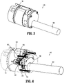
FIG. 3 is a side, perspective view illustrating a transmission assembly of the handle assembly ofFIG. 2 ; -
FIG. 4 is a side, perspective view, illustrating internal components of the transmission assembly ofFIG. 3 ; -
FIG. 5 is a perspective view illustrating the internal components of the transmission assembly ofFIG. 4 ; -
FIG. 6 is a cross-sectional view illustrating the internal components of the transmission assembly ofFIG. 4 ; -
FIG. 7 is a side, perspective view illustrating a selector cam and a selector motor of the transmission assembly ofFIG. 4 ; and -
FIG. 8 is an enlarged perspective view illustrating a shaft lockout of the transmission assembly ofFIG. 4 . - Embodiments of the presently disclosed surgical instruments are described in detail with reference to the drawings, in which like reference numerals designate identical or corresponding elements in each of the several views. As used herein the term "distal" refers to that portion of the surgical instrument, or component thereof, farther from the user, while the term "proximal" refers to that portion of the surgical instrument, or component thereof, closer to the user.
- This disclosure is directed to a transmission assembly disposable within a handle housing of a hand-held surgical instrument. The transmission assembly has a single motor that drives a plurality of output shafts, which are configured to transmit rotational motion to corresponding driven elements of a surgical end effector. The transmission assembly includes a selector cam that selectively operably couples a single output shaft with the motor. When a user depresses a switch, a computer processor within the handle housing determines the desired user request and positions the selector cam in the appropriate position to operate the desired output shaft.
- The main advantage of a single motor design is the elimination of motors due to the simple shaft selectable transmission. This transmission design provides the same device performance as a multiple motor design with the advantages of allowing the product to be manufactured at a lower cost. Further, the ergonomics are improved because the physical size and weight of the device will be less and will require fewer electrical components and circuitry which contributes to improved reliability.
- With reference to
FIGS. 1 and 2 , a surgical instrument, in accordance with an embodiment of the disclosure, is generally designated as 10, and is in the form of a powered hand-held electromechanical surgical instrument configured for selective coupling thereto of a plurality of different surgical end effectors (not explicitly shown), for example, a linear surgical stapler end effector, a circular stapler end effector, a hernia tack end effector, or the like. An exemplary end effector configured for actuation and manipulation by the powered hand-held electromechanicalsurgical instrument 10 may be found at least inU.S. Patent No. 8,011,555 , the entire contents of which being incorporated by reference herein. - The hand-held electromechanical
surgical instrument 10 includes ahandle assembly 12 and anadapter assembly 14 extending distally from thehandle assembly 12. Theadapter assembly 14 has aknob housing 16 coupled to thehandle assembly 12 and ashaft portion 18 configured for selective connection with a selected surgical end effector. Theknob housing 16 may be rotationally coupled to thehandle assembly 12 and configured to be manually rotated about a longitudinal axis "X" defined by theshaft portion 18 to rotate the end effector. - The
handle assembly 12 includes ahandle housing 26 consisting of abarrel portion 28 substantially aligned with the longitudinal axis "X," and ahandle portion 30 extending perpendicularly downward from thebarrel portion 28. Thehandle assembly 12 includes a printed circuit board orprocessor 36 and abattery 38 disposed in thehandle housing 26. The printedcircuit board 36 is configured to be in electrical communication with thebattery 38 and amain drive motor 102 of atransmission assembly 100. Themain drive motor 102 may be wirelessly connected, connected via a wire, or otherwise electrically connected to the printedcircuit board 36 and thebattery 38. Thehandle assembly 12 also has afire switch 22 configured to actuate the various functions of the end effector and asafety switch 24 for preventing an inadvertent actuation of thefire switch 22. Thefire switch 22 may be a finger switch pivotably coupled to thehandle portion 30 in communication with the printedcircuit board 36 for activating thebattery 38 to ultimately actuate an open/close and staple firing function of the end effector. - With reference to
FIGS. 3-8 , thetransmission assembly 100 of thehandle assembly 12 is configured for removable receipt in thebarrel portion 28 of thehandle housing 26 and generally includes a body portion orhousing 104, themain drive motor 102, a plurality ofoutput shafts selector cam 160, and aselector motor 162. Themain drive motor 102 of thetransmission assembly 100 may be an electric motor and rotatably supports adrive shaft 116 about which amain drive gear 118, such as, for example, a spur gear, is non-rotatably fixed. As such, an actuation of themain drive motor 102 results in a rotation of themain drive gear 118. In aspects, themain drive motor 102 may be considered separate from thetransmission assembly 100. - The
output shafts main drive motor 102 whereby the selectedoutput shaft shaft 2 ofadapter assembly 14 ofFIG. 1 ) to ultimately effect a corresponding function of the attached surgical end effector. Theoutput shafts transmission housing 104 and are resisted from sliding within thetransmission housing 104 byseals 112. Each of theoutput shafts distal end 114 configured to non-rotatably couple to the respective driven element of theadapter assembly 14. - With reference to
FIGS. 4-8 , thetransmission assembly 100 further includes a plurality of output gears, such as, first, second, and third output spur gears 120, 122, 124 rotationally supported in thetransmission housing 104 and about therespective output shafts respective output shafts output shafts intermediate output gear 120 is in direct meshing engagement with themain drive gear 118, whereas the second and third output gears 122, 124 are operably coupled to themain drive gear 118 via thefirst output gear 120. In this way, an actuation of themain drive motor 102 results in the simultaneous rotation of each of the first, second, and third output gears 120, 122, 124. - The
transmission assembly 100 further includes a plurality of coupling shafts, such as, for example, first, second, andthird coupling shafts third output shafts coupling shafts output shafts output shafts FIG. 6 ) between a proximal position and a distal position. Thetransmission assembly 100 may include a plurality of biasing members, such as, for example, first second, and third coil springs 136, 138, 140 configured to resiliently bias thecoupling shafts output shafts coupling shafts FIGS. 7-8 ) that extends through aslit 144 defined in each of theoutput shafts third output shafts third coupling shafts - Each of the
coupling shafts proximal end portion 150a (FIG. 6 ) that protrudes proximally from therespective output shafts transmission housing 104, and adistal end portion 150b received in therespective output shaft distal end portion 150b of each of thecoupling shafts gear 152 formed therewith or fixed thereabout, and each of the output gears 120, 122, 124 has an inner gearedsurface 154 configured to meshingly engage with therespective gear 152 of thecoupling shaft coupling shafts coupling shaft corresponding output gear coupling shaft corresponding output shaft coupling shaft gear 152 of the selectedcoupling shaft inner surface 154 of therespective output gear output gear coupling shaft output shaft - With continued reference to
FIGS. 4-8 , theselector cam 160 of thetransmission assembly 100 is operably coupled to theselector motor 162 and is configured to maintain only one of thecoupling shafts main drive motor 102 at a time. Theselector motor 162 may be an electric stepper motor and rotatably supports agear 164. Theselector cam 160 has a generally arcuate shape and is disposed about themain drive motor 102. Theselector cam 160 has an outercircumferential edge 166 having a plurality ofteeth 168 in meshing engagement with thegear 164 of theselector motor 162 such that actuation of theselector motor 162 moves theselector cam 160 about themain drive motor 102 between a plurality of discrete positions. - As best shown in
FIGS. 5-6 , theselector cam 160 has a distal-facingsurface 170 engaged with theproximal end portion 150a of each of thecoupling shafts surface 170 of theselector cam 160 has opposing first and second rampedend portions recess 174 disposed centrally between the first and second rampedend portions recess 174 is defined by a pair of rampedsegments surface 170. Theselector cam 160, in response to an actuation of theselector motor 162, is configured to move along an arcuate path between a first position (FIG. 4 ), a second position, and a third position (e.g., as illustrated by double-headed arrows ofFIGS. 4 and7 ). - When the
selector cam 160 is in the first position, the first orcentral coupling shaft 130 is aligned with therecess 174 and therefore in the proximal position, and the second andthird coupling shafts surface 170 of theselector cam 160. When theselector cam 160 is in the second position (not explicitly shown), thesecond coupling shaft 132 is disposed out of alignment with the distal-facingsurface 170 of theselector cam 160 and therefore in the proximal position, and the first andthird coupling shafts surface 170. When theselector cam 160 is in the third position (not explicitly shown), thethird coupling shaft 134 is out of alignment with the distal-facingsurface 170 and therefore in the proximal position, and the first andsecond coupling shafts surface 170. - With brief reference to
FIGS. 7-8 , thetransmission assembly 100 may further include abracket 180 disposed about each of theoutput shafts transmission housing 104. Thebracket 180 defines a plurality ofapertures 182 configured for receipt of thetab 142 of therespective coupling shafts coupling shafts tab 142 of each thecoupling shafts respective aperture 182 of thebracket 180, inadvertent rotation of thecoupling shafts respective output shafts - In operation, a user may manually select the desired function of the end effector to be carried out by the
handle assembly 12. For example, a user may desire for an opening/closing of the attached end effector. The processor 36 (FIG. 2 ) of thehandle assembly 12 translates this command into an appropriate operation of the first orcentral output shaft 106 of thetransmission assembly 100. To enable operation of thefirst output shaft 106, theprocessor 36 actuates theselector motor 162 to move theselector cam 160 into the first position, as shown inFIGS. 5 and 6 . As theselector cam 160 is moved toward the first position, in response to an activation of theselector motor 162, therecess 174 in the distal-facingsurface 170 of theselector cam 160 moves into alignment with thefirst coupling shaft 130 of thetransmission assembly 100 whereby the resilient bias of the biasingmember 136 is allowed to drive thefirst coupling shaft 130 into the proximal position. In the proximal position, theproximal end portion 150a of thefirst coupling shaft 130 is received in therecess 174 of theselector cam 160. With theselector cam 160 in the first position, the second andthird coupling shafts surface 170 of theselector cam 160. - With the
selector cam 160 in the selected first position, thehandle assembly 12 may generate an indication (e.g., an auditory or visual indication) to the user that thehandle assembly 12 is ready to be actuated to perform the desired function. A user may then actuate the fire switch 22 (FIG. 1 ) of thehandle assembly 12, whereby themain drive motor 102 drives a rotation of themain drive gear 118, which drives a concomitant rotation of each of the output gears 120, 122, 124. However, since only thefirst coupling shaft 130 of the plurality ofcoupling shafts selector cam 160 being set in the first position, only thefirst coupling shaft 130 is operably engaged with themain drive gear 118. In particular, the gear 152 (FIG. 6 ) of thefirst coupling shaft 130 is in meshing engagement with the gearedinner surface 154 of thefirst output gear 120 such that the rotation of thefirst output gear 120 results in rotation of thefirst coupling shaft 130 and, in turn, rotation of thefirst output shaft 106. In contrast, the second andthird output shafts gear 152 of the respective second andthird coupling shafts - If a user desires that another type of function of the end effector be carried out by the
handle assembly 12, theselector cam 160 may be moved to the corresponding position, for example, the second position. As theselector cam 160 is moved from the first position to the second position (e.g., as illustrated by double-headed arrows ofFIGS. 4 and7 ), the rampedsegment 174a of the distal-facingsurface 170 of theselector cam 160 distally drives thefirst coupling member 130 from the proximal position toward the distal position against the resilient bias of the biasing member 136 (e.g., as illustrated by double headed arrow ofFIG. 6 ). With theselector cam 160 in the second position, the distal-facingsurface 170 of theselector cam 160 maintains thethird coupling member 134 in the distal position. Simultaneously, the distal-facingsurface 170 of theselector cam 160 moves out of alignment with the second coupling member 132 (e.g., theselector cam 160 is disengaged from the second coupling member 132) to allow thesecond coupling member 132 to move to the proximal position in which thegear 152 of thesecond coupling member 132 engages the gearedinner surface 154 of thesecond output gear 122. In this configuration, an activation of themain drive motor 102 ultimately results in the rotation of only thesecond output shaft 108 among the plurality ofoutput shafts - Any of the components described herein may be fabricated from either metals, plastics, resins, composites or the like taking into consideration strength, durability, wearability, weight, resistance to corrosion, ease of manufacturing, cost of manufacturing, and the like.
- It will be understood that various modifications may be made to the embodiments of the presently disclosed surgical instruments including switch assemblies. Therefore, the above description should not be construed as limiting, but merely as exemplifications of embodiments. Those skilled in the art will envision other modifications within the scope and spirit of the disclosure.
- The invention may be described by reference to the following numbered paragraphs:-1. A transmission assembly for use in a hand-held surgical instrument, the transmission assembly comprising:
- a housing;
- a main drive motor supporting a main drive gear;
- first and second output gears operably coupled to the main drive gear and configured to rotate in response to a rotation of the main drive gear;
- first and second output shafts rotatably supported in the housing; and
- a selector cam associated with the first and second output shafts, wherein the selector cam is configured to move between a first position, in which the selector cam non-rotatably couples the first output shaft to the first output gear and the second output gear is rotatable relative to the second output shaft, and a second position, in which the selector cam non-rotatably couples the second output shaft to the second output gear and the first output gear is rotatable relative to the first output shaft.
- 2. The transmission assembly according to paragraph 1, further comprising:
- a first coupling shaft non-rotatably coupled to the first output shaft, wherein the first coupling shaft is configured to non-rotatably engage the first output gear when the selector cam is in the first position such that only the first output shaft of the first and second output shafts rotates in response to the rotation of the main drive gear; and
- a second coupling shaft non-rotatably coupled to the second output shaft, wherein the second coupling shaft is configured to non-rotatably engage the second output gear when the selector cam is in the second position such that only the second output shaft of the first and second output shafts rotates in response to the rotation of the main drive gear.
- 3. The transmission assembly according to
paragraph 2, wherein the first coupling shaft extends through the first output gear and is slidable therein between a proximal position, in which the first coupling shaft is non-rotatably engaged with the first output gear, and a distal position, in which the first coupling shaft is disengaged from the first output gear. - 4. The transmission assembly according to paragraph 3, wherein the first coupling shaft has a proximal end portion engaged with the selector cam, and a distal end portion having a gear, the first output gear having a geared inner surface configured to meshingly engage with the gear of the distal end portion of the first coupling shaft when the first coupling shaft is in the proximal position.
- 5. The transmission assembly according to paragraph 3, wherein the selector cam has a distal-facing surface engaged to the first and second coupling shafts, the distal-facing surface of the selector cam having a recess in which a proximal end portion of the first coupling shaft is received when the selector cam is in the first position.
- 6. The transmission assembly according to paragraph 5, wherein the selector cam has an arcuate shape and is configured to rotate around the main drive motor between the first and second positions.
- 7. The transmission assembly according to paragraph 5, wherein the distal-facing surface of the selector cam has a first ramped end portion, and an opposite second ramped end portion.
- 8. The transmission assembly according to paragraph 3, wherein the first and second coupling shafts are each resiliently biased toward the proximal position, the selector cam being configured to selectively maintain only one of the first or second coupling shafts in the distal position.
- 9. The transmission assembly according to paragraph 1, further comprising:
- a third output shaft; and
- a third output gear operably coupled to the main drive gear, wherein the selector cam is configured to move to a third position, in which the first and second output shafts are disengaged from the respective first and second output gears and the third output shaft is non-rotatably engaged to the third output gear.
- 10. The transmission assembly according to paragraph 1, further comprising a selector motor supporting a gear operably coupled to the selector cam and configured to move the selector cam between the first and second positions.
- 11. The transmission assembly according to
paragraph 10, wherein the selector cam has a plurality of teeth in meshing engagement with the gear of the selector motor. - 12. A handle assembly for operating a surgical end effector, the handle assembly comprising:
- a handle housing having a barrel portion, and a handle portion extending from the barrel portion; and
- a transmission assembly supported in the barrel portion of the handle housing and including:
- a main drive motor having a main drive gear;
- first, second, and third output shafts;
- first, second, and third output gears operably coupled to the main drive gear and configured to rotate in response to a rotation of the main drive gear;
- a selector cam; and
- a selector motor operably coupled to the selector cam and configured to move the selector cam relative to the first, second, and third output shafts between a first position, in which the first output shaft is non-rotatably coupled to the first output gear, a second position, in which the second output shaft is non-rotatably coupled to the second output gear, and a third position in which the third output shaft is non-rotatably coupled to the third output gear.
- 13. The handle assembly according to
paragraph 12, wherein the transmission assembly further includes:- a first coupling shaft non-rotatably coupled to the first output shaft;
- a second coupling shaft non-rotatably coupled to the second output shaft; and
- a third coupling shaft non-rotatably coupled to the third output shaft, wherein the first coupling shaft is configured to translate into non-rotatable engagement with the first output gear when the selector cam is moved to the first position such that only the first output shaft rotates in response to a rotation of the main drive gear when the selector cam is in the first position, wherein the second coupling shaft is configured to translate into non-rotatable engagement with the second output gear when the selector cam is moved to the second position such that only the second output shaft rotates in response to the rotation of the main drive gear when the selector cam is in the second position, and wherein the third coupling shaft is configured to translate into non-rotatable engagement with the third output gear when the selector cam is moved to the third position such that only the third output shaft rotates in response to the rotation of the main drive gear when the selector cam is in the third position.
- 14. The handle assembly according to paragraph 13, wherein the first, second, and third coupling shafts are each resiliently biased toward a proximal position in which the first, second, and third coupling shafts are respectively non-rotatably engaged with the first, second, and third output gears, the selector cam being configured to selectively maintain only one of the first, second, or third coupling shafts in a distal position and out of non-rotatable engagement with the respective first, second, and third output gears.
- 15. The handle assembly according to
paragraph 14, wherein the selector cam has a distal-facing surface configured to engage and maintain a selected one of the first, second, or third coupling shafts in the distal position. - 16. The handle assembly according to
paragraph 12, wherein the transmission assembly further includes a first coupling shaft non-rotatably coupled to the first output shaft, wherein the first coupling shaft is configured to translate into non-rotatable engagement with the first output gear when the selector cam is moved to the first position such that only the first output shaft rotates in response to a rotation of the main drive gear when the selector cam is in the first position. - 17. The handle assembly according to
paragraph 16, wherein the first coupling shaft extends through the first output gear and is slidable therein between a proximal position, in which the first coupling shaft is non-rotatably engaged with the first output gear, and a distal position, in which the first coupling shaft is disengaged from the first output gear. - 18. The handle assembly according to paragraph 17, wherein the first coupling shaft has a proximal end portion engaged with the selector cam, and a distal end portion having a gear, the first output gear having a geared inner surface configured to meshingly engage with the gear of the distal end portion of the first coupling shaft when the first coupling shaft is in the proximal position.
- 19. The handle assembly according to
paragraph 12, wherein the selector motor rotatably supports and drives a gear, the selector cam having a plurality of teeth in meshing engagement with the gear of the selector motor and configured to move the selector cam between the first, second, and third positions. - 20. The handle assembly according to paragraph 19, wherein the selector cam has an arcuate shape and is configured to rotate around the main drive motor between the first, second, and third positions.
Claims (14)
- A transmission assembly for use in a hand-held surgical instrument, the transmission assembly comprising:a housing;a main drive motor supporting a main drive gear;first and second output gears operably coupled to the main drive gear and configured to rotate in response to a rotation of the main drive gear;first and second output shafts rotatably supported in the housing; anda selector cam associated with the first and second output shafts, wherein the selector cam is configured to move between a first position, in which the selector cam non-rotatably couples the first output shaft to the first output gear and the second output gear is rotatable relative to the second output shaft, and a second position, in which the selector cam non-rotatably couples the second output shaft to the second output gear and the first output gear is rotatable relative to the first output shaft.
- The transmission assembly according to claim 1, further comprising:a first coupling shaft non-rotatably coupled to the first output shaft, wherein the first coupling shaft is configured to non-rotatably engage the first output gear when the selector cam is in the first position such that only the first output shaft of the first and second output shafts rotates in response to the rotation of the main drive gear; anda second coupling shaft non-rotatably coupled to the second output shaft, wherein the second coupling shaft is configured to non-rotatably engage the second output gear when the selector cam is in the second position such that only the second output shaft of the first and second output shafts rotates in response to the rotation of the main drive gear.
- The transmission assembly according to claim 2, wherein the first coupling shaft extends through the first output gear and is slidable therein between a proximal position, in which the first coupling shaft is non-rotatably engaged with the first output gear, and a distal position, in which the first coupling shaft is disengaged from the first output gear; preferably wherein the first coupling shaft has a proximal end portion engaged with the selector cam, and a distal end portion having a gear, the first output gear having a geared inner surface configured to meshingly engage with the gear of the distal end portion of the first coupling shaft when the first coupling shaft is in the proximal position.
- The transmission assembly according to claim 3, wherein the selector cam has a distal-facing surface engaged to the first and second coupling shafts, the distal-facing surface of the selector cam having a recess in which a proximal end portion of the first coupling shaft is received when the selector cam is in the first position; preferably wherein the selector cam has an arcuate shape and is configured to rotate around the main drive motor between the first and second positions.
- The transmission assembly according to claim 4, wherein the distal-facing surface of the selector cam has a first ramped end portion, and an opposite second ramped end portion.
- The transmission assembly according to claim 3, wherein the first and second coupling shafts are each resiliently biased toward the proximal position, the selector cam being configured to selectively maintain only one of the first or second coupling shafts in the distal position.
- The transmission assembly according to any preceding claim, further comprising:a third output shaft; anda third output gear operably coupled to the main drive gear, wherein the selector cam is configured to move to a third position, in which the first and second output shafts are disengaged from the respective first and second output gears and the third output shaft is non-rotatably engaged to the third output gear.
- The transmission assembly according to any preceding claim, further comprising a selector motor supporting a gear operably coupled to the selector cam and configured to move the selector cam between the first and second positions; preferably wherein the selector cam has a plurality of teeth in meshing engagement with the gear of the selector motor.
- A handle assembly for operating a surgical end effector, the handle assembly comprising:a handle housing having a barrel portion, and a handle portion extending from the barrel portion; anda transmission assembly supported in the barrel portion of the handle housing and including:a main drive motor having a main drive gear;first, second, and third output shafts;first, second, and third output gears operably coupled to the main drive gear and configured to rotate in response to a rotation of the main drive gear;a selector cam; anda selector motor operably coupled to the selector cam and configured to move the selector cam relative to the first, second, and third output shafts between a first position, in which the first output shaft is non-rotatably coupled to the first output gear, a second position, in which the second output shaft is non-rotatably coupled to the second output gear, and a third position in which the third output shaft is non-rotatably coupled to the third output gear.
- The handle assembly according to claim 9, wherein the transmission assembly further includes:a first coupling shaft non-rotatably coupled to the first output shaft;a second coupling shaft non-rotatably coupled to the second output shaft; anda third coupling shaft non-rotatably coupled to the third output shaft, wherein the first coupling shaft is configured to translate into non-rotatable engagement with the first output gear when the selector cam is moved to the first position such that only the first output shaft rotates in response to a rotation of the main drive gear when the selector cam is in the first position, wherein the second coupling shaft is configured to translate into non-rotatable engagement with the second output gear when the selector cam is moved to the second position such that only the second output shaft rotates in response to the rotation of the main drive gear when the selector cam is in the second position, and wherein the third coupling shaft is configured to translate into non-rotatable engagement with the third output gear when the selector cam is moved to the third position such that only the third output shaft rotates in response to the rotation of the main drive gear when the selector cam is in the third position.
- The handle assembly according to claim 10, wherein the first, second, and third coupling shafts are each resiliently biased toward a proximal position in which the first, second, and third coupling shafts are respectively non-rotatably engaged with the first, second, and third output gears, the selector cam being configured to selectively maintain only one of the first, second, or third coupling shafts in a distal position and out of non-rotatable engagement with the respective first, second, and third output gears; preferably wherein the selector cam has a distal-facing surface configured to engage and maintain a selected one of the first, second, or third coupling shafts in the distal position.
- The handle assembly according to claim 11, wherein the transmission assembly further includes a first coupling shaft non-rotatably coupled to the first output shaft, wherein the first coupling shaft is configured to translate into non-rotatable engagement with the first output gear when the selector cam is moved to the first position such that only the first output shaft rotates in response to a rotation of the main drive gear when the selector cam is in the first position; preferably wherein the first coupling shaft extends through the first output gear and is slidable therein between a proximal position, in which the first coupling shaft is non-rotatably engaged with the first output gear, and a distal position, in which the first coupling shaft is disengaged from the first output gear.
- The handle assembly according to claim 12, wherein the first coupling shaft has a proximal end portion engaged with the selector cam, and a distal end portion having a gear, the first output gear having a geared inner surface configured to meshingly engage with the gear of the distal end portion of the first coupling shaft when the first coupling shaft is in the proximal position.
- The handle assembly according to any of claims 10 to 13, wherein the selector motor rotatably supports and drives a gear, the selector cam having a plurality of teeth in meshing engagement with the gear of the selector motor and configured to move the selector cam between the first, second, and third positions; and/or wherein the selector cam has an arcuate shape and is configured to rotate around the main drive motor between the first, second, and third positions.
Applications Claiming Priority (1)
| Application Number | Priority Date | Filing Date | Title |
|---|---|---|---|
| US17/121,843 US11802609B2 (en) | 2020-12-15 | 2020-12-15 | Handle assemblies for hand-held surgical instruments |
Publications (2)
| Publication Number | Publication Date |
|---|---|
| EP4014892A1 true EP4014892A1 (en) | 2022-06-22 |
| EP4014892B1 EP4014892B1 (en) | 2024-11-27 |
Family
ID=78845116
Family Applications (1)
| Application Number | Title | Priority Date | Filing Date |
|---|---|---|---|
| EP21214081.8A Active EP4014892B1 (en) | 2020-12-15 | 2021-12-13 | Handle assemblies for hand-held surgical instruments |
Country Status (4)
| Country | Link |
|---|---|
| US (1) | US11802609B2 (en) |
| EP (1) | EP4014892B1 (en) |
| CN (1) | CN114631855B (en) |
| CA (1) | CA3137613A1 (en) |
Families Citing this family (1)
| Publication number | Priority date | Publication date | Assignee | Title |
|---|---|---|---|---|
| CN115153395B (en) * | 2022-08-18 | 2024-05-17 | 湖南省华芯医疗器械有限公司 | Reusable section, operating handle and endoscope |
Citations (4)
| Publication number | Priority date | Publication date | Assignee | Title |
|---|---|---|---|---|
| US8011555B2 (en) | 2007-03-06 | 2011-09-06 | Tyco Healthcare Group Lp | Surgical stapling apparatus |
| US20170175852A1 (en) * | 2015-12-22 | 2017-06-22 | Covidien Lp | Electromechanical surgical devices with single motor drives and adapter assemblies therfor |
| EP3488801A1 (en) * | 2017-10-30 | 2019-05-29 | Ethicon LLC | Surgical instruments comprising a lockable end effector socket |
| US10405857B2 (en) * | 2013-04-16 | 2019-09-10 | Ethicon Llc | Powered linear surgical stapler |
Family Cites Families (16)
| Publication number | Priority date | Publication date | Assignee | Title |
|---|---|---|---|---|
| US8968276B2 (en) * | 2007-09-21 | 2015-03-03 | Covidien Lp | Hand held surgical handle assembly, surgical adapters for use between surgical handle assembly and surgical end effectors, and methods of use |
| EP2197363B1 (en) | 2007-09-21 | 2016-11-02 | Covidien LP | Surgical device |
| US9216013B2 (en) * | 2013-02-18 | 2015-12-22 | Covidien Lp | Apparatus for endoscopic procedures |
| US9517065B2 (en) * | 2013-02-28 | 2016-12-13 | Ethicon Endo-Surgery, Llc | Integrated tissue positioning and jaw alignment features for surgical stapler |
| US9510827B2 (en) * | 2013-03-25 | 2016-12-06 | Covidien Lp | Micro surgical instrument and loading unit for use therewith |
| KR102455799B1 (en) | 2014-03-31 | 2022-10-18 | 인튜어티브 서지컬 오퍼레이션즈 인코포레이티드 | Surgical instrument with shiftable transmission |
| US20150374372A1 (en) * | 2014-06-26 | 2015-12-31 | Covidien Lp | Hand held surgical handle assembly, surgical adapters for use between surgical handle assembly and surgical end effectors, and methods of use |
| EP3193742B1 (en) * | 2014-09-15 | 2020-04-29 | Applied Medical Resources Corporation | Surgical stapler with self-adjusting staple height |
| US10180463B2 (en) * | 2015-02-27 | 2019-01-15 | Ethicon Llc | Surgical apparatus configured to assess whether a performance parameter of the surgical apparatus is within an acceptable performance band |
| CN107530078B (en) * | 2015-04-22 | 2021-03-05 | 柯惠Lp公司 | Hand-held electromechanical surgical system |
| US10117650B2 (en) * | 2015-05-05 | 2018-11-06 | Covidien Lp | Adapter assembly and loading units for surgical stapling devices |
| US10039532B2 (en) * | 2015-05-06 | 2018-08-07 | Covidien Lp | Surgical instrument with articulation assembly |
| US10172615B2 (en) * | 2015-05-27 | 2019-01-08 | Covidien Lp | Multi-fire push rod stapling device |
| US10842473B2 (en) * | 2017-10-30 | 2020-11-24 | Ethicon Llc | Surgical instrument having dual rotatable members to effect different types of end effector movement |
| US10779825B2 (en) * | 2017-12-15 | 2020-09-22 | Ethicon Llc | Adapters with end effector position sensing and control arrangements for use in connection with electromechanical surgical instruments |
| US11272948B2 (en) * | 2018-07-10 | 2022-03-15 | Covidien Lp | Hand-held surgical instruments |
-
2020
- 2020-12-15 US US17/121,843 patent/US11802609B2/en active Active
-
2021
- 2021-11-04 CA CA3137613A patent/CA3137613A1/en active Pending
- 2021-12-10 CN CN202111505573.6A patent/CN114631855B/en active Active
- 2021-12-13 EP EP21214081.8A patent/EP4014892B1/en active Active
Patent Citations (4)
| Publication number | Priority date | Publication date | Assignee | Title |
|---|---|---|---|---|
| US8011555B2 (en) | 2007-03-06 | 2011-09-06 | Tyco Healthcare Group Lp | Surgical stapling apparatus |
| US10405857B2 (en) * | 2013-04-16 | 2019-09-10 | Ethicon Llc | Powered linear surgical stapler |
| US20170175852A1 (en) * | 2015-12-22 | 2017-06-22 | Covidien Lp | Electromechanical surgical devices with single motor drives and adapter assemblies therfor |
| EP3488801A1 (en) * | 2017-10-30 | 2019-05-29 | Ethicon LLC | Surgical instruments comprising a lockable end effector socket |
Also Published As
| Publication number | Publication date |
|---|---|
| EP4014892B1 (en) | 2024-11-27 |
| CA3137613A1 (en) | 2022-06-15 |
| US20220186815A1 (en) | 2022-06-16 |
| US11802609B2 (en) | 2023-10-31 |
| CN114631855A (en) | 2022-06-17 |
| CN114631855B (en) | 2026-07-28 |
Similar Documents
| Publication | Publication Date | Title |
|---|---|---|
| CN114173682B (en) | Handheld electromechanical surgical instruments | |
| US10446342B2 (en) | Surgical instruments and switch assemblies thereof | |
| US10709437B2 (en) | Suturing instrument with motorized needle drive | |
| US9839419B2 (en) | Suturing instrument with jaw having integral cartridge component | |
| EP3278743B1 (en) | Variable speed control of powered surgical device | |
| US11510669B2 (en) | Hand-held surgical instruments | |
| CN101801284B (en) | Surgical Instruments | |
| CN112971890B (en) | Handheld surgical instruments | |
| US11819260B2 (en) | Detent feature for articulation control in surgical instrument | |
| EP3834744A2 (en) | Hand-held electromechanical surgical instruments | |
| EP4014892B1 (en) | Handle assemblies for hand-held surgical instruments | |
| EP3888568A2 (en) | Hand-held surgical instruments | |
| US11395655B2 (en) | Hand-held surgical instruments |
Legal Events
| Date | Code | Title | Description |
|---|---|---|---|
| PUAI | Public reference made under article 153(3) epc to a published international application that has entered the european phase |
Free format text: ORIGINAL CODE: 0009012 |
|
| STAA | Information on the status of an ep patent application or granted ep patent |
Free format text: STATUS: THE APPLICATION HAS BEEN PUBLISHED |
|
| AK | Designated contracting states |
Kind code of ref document: A1 Designated state(s): AL AT BE BG CH CY CZ DE DK EE ES FI FR GB GR HR HU IE IS IT LI LT LU LV MC MK MT NL NO PL PT RO RS SE SI SK SM TR |
|
| STAA | Information on the status of an ep patent application or granted ep patent |
Free format text: STATUS: REQUEST FOR EXAMINATION WAS MADE |
|
| 17P | Request for examination filed |
Effective date: 20221216 |
|
| RBV | Designated contracting states (corrected) |
Designated state(s): AL AT BE BG CH CY CZ DE DK EE ES FI FR GB GR HR HU IE IS IT LI LT LU LV MC MK MT NL NO PL PT RO RS SE SI SK SM TR |
|
| GRAP | Despatch of communication of intention to grant a patent |
Free format text: ORIGINAL CODE: EPIDOSNIGR1 |
|
| STAA | Information on the status of an ep patent application or granted ep patent |
Free format text: STATUS: GRANT OF PATENT IS INTENDED |
|
| RIC1 | Information provided on ipc code assigned before grant |
Ipc: A61B 17/00 20060101ALN20240607BHEP Ipc: A61B 17/068 20060101AFI20240607BHEP |
|
| INTG | Intention to grant announced |
Effective date: 20240628 |
|
| RIC1 | Information provided on ipc code assigned before grant |
Ipc: A61B 17/00 20060101ALN20240617BHEP Ipc: A61B 17/068 20060101AFI20240617BHEP |
|
| GRAS | Grant fee paid |
Free format text: ORIGINAL CODE: EPIDOSNIGR3 |
|
| GRAA | (expected) grant |
Free format text: ORIGINAL CODE: 0009210 |
|
| STAA | Information on the status of an ep patent application or granted ep patent |
Free format text: STATUS: THE PATENT HAS BEEN GRANTED |
|
| AK | Designated contracting states |
Kind code of ref document: B1 Designated state(s): AL AT BE BG CH CY CZ DE DK EE ES FI FR GB GR HR HU IE IS IT LI LT LU LV MC MK MT NL NO PL PT RO RS SE SI SK SM TR |
|
| REG | Reference to a national code |
Ref country code: GB Ref legal event code: FG4D |
|
| REG | Reference to a national code |
Ref country code: CH Ref legal event code: EP |
|
| REG | Reference to a national code |
Ref country code: IE Ref legal event code: FG4D |
|
| REG | Reference to a national code |
Ref country code: DE Ref legal event code: R096 Ref document number: 602021022350 Country of ref document: DE |
|
| REG | Reference to a national code |
Ref country code: LT Ref legal event code: MG9D |
|
| REG | Reference to a national code |
Ref country code: NL Ref legal event code: MP Effective date: 20241127 |
|
| PG25 | Lapsed in a contracting state [announced via postgrant information from national office to epo] |
Ref country code: HR Free format text: LAPSE BECAUSE OF FAILURE TO SUBMIT A TRANSLATION OF THE DESCRIPTION OR TO PAY THE FEE WITHIN THE PRESCRIBED TIME-LIMIT Effective date: 20241127 Ref country code: IS Free format text: LAPSE BECAUSE OF FAILURE TO SUBMIT A TRANSLATION OF THE DESCRIPTION OR TO PAY THE FEE WITHIN THE PRESCRIBED TIME-LIMIT Effective date: 20250327 Ref country code: PT Free format text: LAPSE BECAUSE OF FAILURE TO SUBMIT A TRANSLATION OF THE DESCRIPTION OR TO PAY THE FEE WITHIN THE PRESCRIBED TIME-LIMIT Effective date: 20250327 |
|
| PG25 | Lapsed in a contracting state [announced via postgrant information from national office to epo] |
Ref country code: FI Free format text: LAPSE BECAUSE OF FAILURE TO SUBMIT A TRANSLATION OF THE DESCRIPTION OR TO PAY THE FEE WITHIN THE PRESCRIBED TIME-LIMIT Effective date: 20241127 Ref country code: NL Free format text: LAPSE BECAUSE OF FAILURE TO SUBMIT A TRANSLATION OF THE DESCRIPTION OR TO PAY THE FEE WITHIN THE PRESCRIBED TIME-LIMIT Effective date: 20241127 |
|
| REG | Reference to a national code |
Ref country code: AT Ref legal event code: MK05 Ref document number: 1744928 Country of ref document: AT Kind code of ref document: T Effective date: 20241127 |
|
| PG25 | Lapsed in a contracting state [announced via postgrant information from national office to epo] |
Ref country code: BG Free format text: LAPSE BECAUSE OF FAILURE TO SUBMIT A TRANSLATION OF THE DESCRIPTION OR TO PAY THE FEE WITHIN THE PRESCRIBED TIME-LIMIT Effective date: 20241127 |
|
| PG25 | Lapsed in a contracting state [announced via postgrant information from national office to epo] |
Ref country code: ES Free format text: LAPSE BECAUSE OF FAILURE TO SUBMIT A TRANSLATION OF THE DESCRIPTION OR TO PAY THE FEE WITHIN THE PRESCRIBED TIME-LIMIT Effective date: 20241127 |
|
| PG25 | Lapsed in a contracting state [announced via postgrant information from national office to epo] |
Ref country code: NO Free format text: LAPSE BECAUSE OF FAILURE TO SUBMIT A TRANSLATION OF THE DESCRIPTION OR TO PAY THE FEE WITHIN THE PRESCRIBED TIME-LIMIT Effective date: 20250227 |
|
| PG25 | Lapsed in a contracting state [announced via postgrant information from national office to epo] |
Ref country code: GR Free format text: LAPSE BECAUSE OF FAILURE TO SUBMIT A TRANSLATION OF THE DESCRIPTION OR TO PAY THE FEE WITHIN THE PRESCRIBED TIME-LIMIT Effective date: 20250228 Ref country code: LV Free format text: LAPSE BECAUSE OF FAILURE TO SUBMIT A TRANSLATION OF THE DESCRIPTION OR TO PAY THE FEE WITHIN THE PRESCRIBED TIME-LIMIT Effective date: 20241127 Ref country code: AT Free format text: LAPSE BECAUSE OF FAILURE TO SUBMIT A TRANSLATION OF THE DESCRIPTION OR TO PAY THE FEE WITHIN THE PRESCRIBED TIME-LIMIT Effective date: 20241127 |
|
| PG25 | Lapsed in a contracting state [announced via postgrant information from national office to epo] |
Ref country code: PL Free format text: LAPSE BECAUSE OF FAILURE TO SUBMIT A TRANSLATION OF THE DESCRIPTION OR TO PAY THE FEE WITHIN THE PRESCRIBED TIME-LIMIT Effective date: 20241127 |
|
| PG25 | Lapsed in a contracting state [announced via postgrant information from national office to epo] |
Ref country code: RS Free format text: LAPSE BECAUSE OF FAILURE TO SUBMIT A TRANSLATION OF THE DESCRIPTION OR TO PAY THE FEE WITHIN THE PRESCRIBED TIME-LIMIT Effective date: 20250227 |
|
| PG25 | Lapsed in a contracting state [announced via postgrant information from national office to epo] |
Ref country code: SM Free format text: LAPSE BECAUSE OF FAILURE TO SUBMIT A TRANSLATION OF THE DESCRIPTION OR TO PAY THE FEE WITHIN THE PRESCRIBED TIME-LIMIT Effective date: 20241127 |
|
| PG25 | Lapsed in a contracting state [announced via postgrant information from national office to epo] |
Ref country code: DK Free format text: LAPSE BECAUSE OF FAILURE TO SUBMIT A TRANSLATION OF THE DESCRIPTION OR TO PAY THE FEE WITHIN THE PRESCRIBED TIME-LIMIT Effective date: 20241127 |
|
| PG25 | Lapsed in a contracting state [announced via postgrant information from national office to epo] |
Ref country code: EE Free format text: LAPSE BECAUSE OF FAILURE TO SUBMIT A TRANSLATION OF THE DESCRIPTION OR TO PAY THE FEE WITHIN THE PRESCRIBED TIME-LIMIT Effective date: 20241127 |
|
| PG25 | Lapsed in a contracting state [announced via postgrant information from national office to epo] |
Ref country code: RO Free format text: LAPSE BECAUSE OF FAILURE TO SUBMIT A TRANSLATION OF THE DESCRIPTION OR TO PAY THE FEE WITHIN THE PRESCRIBED TIME-LIMIT Effective date: 20241127 |
|
| PG25 | Lapsed in a contracting state [announced via postgrant information from national office to epo] |
Ref country code: SK Free format text: LAPSE BECAUSE OF FAILURE TO SUBMIT A TRANSLATION OF THE DESCRIPTION OR TO PAY THE FEE WITHIN THE PRESCRIBED TIME-LIMIT Effective date: 20241127 |
|
| PG25 | Lapsed in a contracting state [announced via postgrant information from national office to epo] |
Ref country code: CZ Free format text: LAPSE BECAUSE OF FAILURE TO SUBMIT A TRANSLATION OF THE DESCRIPTION OR TO PAY THE FEE WITHIN THE PRESCRIBED TIME-LIMIT Effective date: 20241127 |
|
| PG25 | Lapsed in a contracting state [announced via postgrant information from national office to epo] |
Ref country code: IT Free format text: LAPSE BECAUSE OF FAILURE TO SUBMIT A TRANSLATION OF THE DESCRIPTION OR TO PAY THE FEE WITHIN THE PRESCRIBED TIME-LIMIT Effective date: 20241127 |
|
| REG | Reference to a national code |
Ref country code: CH Ref legal event code: PL |
|
| PG25 | Lapsed in a contracting state [announced via postgrant information from national office to epo] |
Ref country code: LU Free format text: LAPSE BECAUSE OF NON-PAYMENT OF DUE FEES Effective date: 20241213 |
|
| REG | Reference to a national code |
Ref country code: DE Ref legal event code: R097 Ref document number: 602021022350 Country of ref document: DE |
|
| PG25 | Lapsed in a contracting state [announced via postgrant information from national office to epo] |
Ref country code: SE Free format text: LAPSE BECAUSE OF FAILURE TO SUBMIT A TRANSLATION OF THE DESCRIPTION OR TO PAY THE FEE WITHIN THE PRESCRIBED TIME-LIMIT Effective date: 20241127 |
|
| PG25 | Lapsed in a contracting state [announced via postgrant information from national office to epo] |
Ref country code: MC Free format text: LAPSE BECAUSE OF FAILURE TO SUBMIT A TRANSLATION OF THE DESCRIPTION OR TO PAY THE FEE WITHIN THE PRESCRIBED TIME-LIMIT Effective date: 20241127 |
|
| PLBE | No opposition filed within time limit |
Free format text: ORIGINAL CODE: 0009261 |
|
| STAA | Information on the status of an ep patent application or granted ep patent |
Free format text: STATUS: NO OPPOSITION FILED WITHIN TIME LIMIT |
|
| REG | Reference to a national code |
Ref country code: BE Ref legal event code: MM Effective date: 20241231 |
|
| PG25 | Lapsed in a contracting state [announced via postgrant information from national office to epo] |
Ref country code: BE Free format text: LAPSE BECAUSE OF NON-PAYMENT OF DUE FEES Effective date: 20241231 |
|
| PG25 | Lapsed in a contracting state [announced via postgrant information from national office to epo] |
Ref country code: CH Free format text: LAPSE BECAUSE OF NON-PAYMENT OF DUE FEES Effective date: 20241231 |
|
| PG25 | Lapsed in a contracting state [announced via postgrant information from national office to epo] |
Ref country code: IE Free format text: LAPSE BECAUSE OF NON-PAYMENT OF DUE FEES Effective date: 20241213 |
|
| 26N | No opposition filed |
Effective date: 20250828 |
|
| PGFP | Annual fee paid to national office [announced via postgrant information from national office to epo] |
Ref country code: DE Payment date: 20251126 Year of fee payment: 5 |
|
| PGFP | Annual fee paid to national office [announced via postgrant information from national office to epo] |
Ref country code: FR Payment date: 20251120 Year of fee payment: 5 |
|
| PG25 | Lapsed in a contracting state [announced via postgrant information from national office to epo] |
Ref country code: CY Free format text: LAPSE BECAUSE OF FAILURE TO SUBMIT A TRANSLATION OF THE DESCRIPTION OR TO PAY THE FEE WITHIN THE PRESCRIBED TIME-LIMIT Effective date: 20241127 |
|
| PG25 | Lapsed in a contracting state [announced via postgrant information from national office to epo] |
Ref country code: TR Free format text: LAPSE BECAUSE OF FAILURE TO SUBMIT A TRANSLATION OF THE DESCRIPTION OR TO PAY THE FEE WITHIN THE PRESCRIBED TIME-LIMIT Effective date: 20241127 |
|
| PG25 | Lapsed in a contracting state [announced via postgrant information from national office to epo] |
Ref country code: HU Free format text: LAPSE BECAUSE OF FAILURE TO SUBMIT A TRANSLATION OF THE DESCRIPTION OR TO PAY THE FEE WITHIN THE PRESCRIBED TIME-LIMIT; INVALID AB INITIO Effective date: 20211213 |
|
| PG25 | Lapsed in a contracting state [announced via postgrant information from national office to epo] |
Ref country code: SI Free format text: LAPSE BECAUSE OF FAILURE TO SUBMIT A TRANSLATION OF THE DESCRIPTION OR TO PAY THE FEE WITHIN THE PRESCRIBED TIME-LIMIT Effective date: 20241127 |
|
| PG25 | Lapsed in a contracting state [announced via postgrant information from national office to epo] |
Ref country code: LT Free format text: LAPSE BECAUSE OF FAILURE TO SUBMIT A TRANSLATION OF THE DESCRIPTION OR TO PAY THE FEE WITHIN THE PRESCRIBED TIME-LIMIT Effective date: 20241127 |