EP4014753A1 - Control method and system for controlling a machine for the temperature processing of containers of food products; method for retrofitting such machine - Google Patents
Control method and system for controlling a machine for the temperature processing of containers of food products; method for retrofitting such machine Download PDFInfo
- Publication number
- EP4014753A1 EP4014753A1 EP20215919.0A EP20215919A EP4014753A1 EP 4014753 A1 EP4014753 A1 EP 4014753A1 EP 20215919 A EP20215919 A EP 20215919A EP 4014753 A1 EP4014753 A1 EP 4014753A1
- Authority
- EP
- European Patent Office
- Prior art keywords
- temperature
- processing fluid
- level
- control unit
- collection tank
- Prior art date
- Legal status (The legal status is an assumption and is not a legal conclusion. Google has not performed a legal analysis and makes no representation as to the accuracy of the status listed.)
- Granted
Links
Images


Classifications
-
- F—MECHANICAL ENGINEERING; LIGHTING; HEATING; WEAPONS; BLASTING
- F28—HEAT EXCHANGE IN GENERAL
- F28F—DETAILS OF HEAT-EXCHANGE AND HEAT-TRANSFER APPARATUS, OF GENERAL APPLICATION
- F28F27/00—Control arrangements or safety devices specially adapted for heat-exchange or heat-transfer apparatus
-
- A—HUMAN NECESSITIES
- A23—FOODS OR FOODSTUFFS; TREATMENT THEREOF, NOT COVERED BY OTHER CLASSES
- A23B—PRESERVATION OF FOODS, FOODSTUFFS OR NON-ALCOHOLIC BEVERAGES; CHEMICAL RIPENING OF FRUIT OR VEGETABLES
- A23B2/00—Preservation of foods or foodstuffs, in general
- A23B2/003—Control or safety devices for sterilisation or pasteurisation systems
-
- A—HUMAN NECESSITIES
- A23—FOODS OR FOODSTUFFS; TREATMENT THEREOF, NOT COVERED BY OTHER CLASSES
- A23B—PRESERVATION OF FOODS, FOODSTUFFS OR NON-ALCOHOLIC BEVERAGES; CHEMICAL RIPENING OF FRUIT OR VEGETABLES
- A23B2/00—Preservation of foods or foodstuffs, in general
- A23B2/20—Preservation of foods or foodstuffs, in general by heating materials in packages which are progressively transported, continuously or stepwise, through the apparatus
- A23B2/22—Preservation of foods or foodstuffs, in general by heating materials in packages which are progressively transported, continuously or stepwise, through the apparatus with packages on endless chain or band conveyors
-
- F—MECHANICAL ENGINEERING; LIGHTING; HEATING; WEAPONS; BLASTING
- F28—HEAT EXCHANGE IN GENERAL
- F28C—HEAT-EXCHANGE APPARATUS, NOT PROVIDED FOR IN ANOTHER SUBCLASS, IN WHICH THE HEAT-EXCHANGE MEDIA COME INTO DIRECT CONTACT WITHOUT CHEMICAL INTERACTION
- F28C3/00—Other direct-contact heat-exchange apparatus
- F28C3/005—Other direct-contact heat-exchange apparatus one heat-exchange medium being a solid
-
- B—PERFORMING OPERATIONS; TRANSPORTING
- B65—CONVEYING; PACKING; STORING; HANDLING THIN OR FILAMENTARY MATERIAL
- B65B—MACHINES, APPARATUS OR DEVICES FOR, OR METHODS OF, PACKAGING ARTICLES OR MATERIALS; UNPACKING
- B65B55/00—Preserving, protecting or purifying packages or package contents in association with packaging
- B65B55/02—Sterilising, e.g. of complete packages
- B65B55/12—Sterilising contents prior to, or during, packaging
- B65B55/14—Sterilising contents prior to, or during, packaging by heat
-
- F—MECHANICAL ENGINEERING; LIGHTING; HEATING; WEAPONS; BLASTING
- F28—HEAT EXCHANGE IN GENERAL
- F28D—HEAT-EXCHANGE APPARATUS, NOT PROVIDED FOR IN ANOTHER SUBCLASS, IN WHICH THE HEAT-EXCHANGE MEDIA DO NOT COME INTO DIRECT CONTACT
- F28D21/00—Heat-exchange apparatus not covered by any of the groups F28D1/00 - F28D20/00
- F28D2021/0019—Other heat exchangers for particular applications; Heat exchange systems not otherwise provided for
- F28D2021/0042—Other heat exchangers for particular applications; Heat exchange systems not otherwise provided for for foodstuffs
-
- F—MECHANICAL ENGINEERING; LIGHTING; HEATING; WEAPONS; BLASTING
- F28—HEAT EXCHANGE IN GENERAL
- F28D—HEAT-EXCHANGE APPARATUS, NOT PROVIDED FOR IN ANOTHER SUBCLASS, IN WHICH THE HEAT-EXCHANGE MEDIA DO NOT COME INTO DIRECT CONTACT
- F28D21/00—Heat-exchange apparatus not covered by any of the groups F28D1/00 - F28D20/00
- F28D2021/0019—Other heat exchangers for particular applications; Heat exchange systems not otherwise provided for
- F28D2021/0077—Other heat exchangers for particular applications; Heat exchange systems not otherwise provided for for tempering, e.g. with cooling or heating circuits for temperature control of elements
Definitions
- the present invention relates to a control method for controlling a machine, generally intended for temperature processing of containers designed to contain food products; in particular, the following discussion will make explicit reference, without this implying any loss of generality, to the control method of a tunnel pasteurising machine (or pasteuriser) for pasteurising packaged food products.
- the present invention also relates to a control system for controlling a machine for the temperature processing of containers of food products and to a method for retrofitting such machine.
- a tunnel pasteuriser food products to be pasteurised, packaged in bottles, cans or other containers, are fed by a conveyor along a forward movement path, which is usually divided into three main processing zones: a heating zone in which the product temperature is gradually raised; a heat-treatment zone in which the product temperature is brought to, and kept at, a pasteurising temperature for a desired time interval; and a cooling zone in which the product temperature is gradually lowered to a desired output temperature.
- the food products At the end of the temperature processing (i.e. at the output of the pasteuriser), it is required for the food products to have been kept above a predetermined temperature for at least a predetermined time, so as to accumulate at least a predetermined quantity of pasteurisation units (PUs) . In this way, effective pasteurisation of the processed products may be assured.
- PUs pasteurisation units
- Each processing zone is, in turn, divided into a plurality of sub-zones, each one of which is operable and controllable independently of the others.
- the products, in each sub-zone are processed by injecting thereon a flow of a fluid at a desired predetermined temperature.
- the fluid is a liquid, such as water, which is injected, sprayed, or applied in any equivalent manner on the products, although other fluids may as well be used, like a gas, such as air.
- each sub-zone comprises a spraying unit positioned above the forward movement path of the products, and, in a possible solution, at least one collection tank positioned below the same forward movement path to collect the liquid, sprayed by the spraying unit, after it has wet the products.
- the processing liquid fed to the spraying units of the various sub-zones is taken, at least in part, from the collection tanks.
- a process of recirculation is implemented, according to which the liquid fed to the spraying units of the heating sub-zones is taken from the tanks of the cooling sub-zones, whilst the liquid fed to the spraying means of the cooling sub-zones is taken from the tanks of the heating sub-zones.
- the liquid fed to the spraying means of each sub-zone is usually taken directly from the collection tank of that sub-zone.
- tunnel pasteuriser is known from EP2702879 .
- the output temperature of the products at the end of the temperature processing is maintained in a desired range, and a control action is required so that the output temperature is not higher than an upper output temperature threshold.
- the output temperature may further be controlled to be higher than a lower output temperature threshold of the desired range, so as to avoid condensation on the containers of the processed products.
- biochemical quality of the fluid is of the outmost importance for a pasteurising machine pasteurising packaged food products.
- the invention also relates to a control system for a machine for the temperature processing of containers for food products, as claimed in claim 12, and to a method for retrofitting a machine for the temperature processing of containers for food products, as claimed in claim 10.
- Figure 1 schematically shows a tunnel pasteurising machine, denoted as a whole with 1, comprising a control system 100 and a forward movement element 21, which may consist, for example, of one or more conveyor belts or any other type of conveyor, for moving food products packaged in containers 10 along a movement path P.
- a tunnel pasteurising machine denoted as a whole with 1
- a control system 100 and a forward movement element 21, which may consist, for example, of one or more conveyor belts or any other type of conveyor, for moving food products packaged in containers 10 along a movement path P.
- Machine 1 comprises a heating zone 2, a heat treatment zone 3 and a cooling zone 4 positioned one after another along movement path P, in order to carry out pasteurisation of the products in containers 10.
- heating zone 2 the temperature of containers 10 is gradually raised; in heat-treatment zone 3 the temperature of containers 10 is brought to, and kept at, a pasteurising temperature for a desired time interval; and in cooling zone 4 the temperature of containers 10 is gradually lowered to a desired output temperature.
- Each one of the heating, heat treatment and cooling zones 2, 3, 4 is further divided into a number of sub-zones 20a, 20b, 20c positioned one after another along movement path P; in the exemplary embodiment shown in Figure 1 , heating zone 2 is divided into three respective sub-zones.
- Each one of the sub-zones 20a, 20b, 20c is provided with a respective collection tank 5a, 5b, 5c for storing a processing fluid 6 (for example water) and a respective injection assembly 7a, 7b, 7c for injecting processing fluid 6 from the respective collection tank 5a, 5b, 5c onto containers 10 that are carried by movement element 21.
- a processing fluid 6 for example water
- a respective injection assembly 7a, 7b, 7c for injecting processing fluid 6 from the respective collection tank 5a, 5b, 5c onto containers 10 that are carried by movement element 21.
- each tank 5a, 5b, 5c is in fluidic communication with the other tanks 5a, 5b, 5c of the same zone 2, 3 or 4.
- Each injection assembly 7a, 7b, 7c comprises, in turn, a plurality of spraying nozzles 22 for spraying processing fluid 6 onto containers 10.
- collection tanks 5a, 5b, 5c are also adapted to collect processing fluid 6 after it has been sprayed on containers 10 (i.e. after it has exchanged heat with containers 10).
- nozzles 22 and collection tanks 5a, 5b, 5c are positioned above and, respectively, below the forward movement element 21, so as to exploit the gravity effect for the movement of processing fluid 6.
- heating zone 2 only.
- collection tanks 5a, 5b, 5c of heating zone 2 are arranged in succession in such a manner that tank 5a is the upstream-most tank of heating zone 2 and tank 5c is the downstream-most tank of heating zone 2 according to movement path P.
- the temperature of processing fluid 6 inside tank 5b is higher than the temperature of processing fluid 6 inside tank 5a; the temperature of processing fluid 6 inside tank 5c is higher than the temperature of processing fluid 6 inside tank 5b.
- Machine 1 further comprises an inlet valve 8 for the inlet of a fresh processing fluid 9 from outside machine 1.
- fresh processing fluid 9 is a processing fluid that has not yet been inlet and processed in machine 1.
- processing fluid 6 and fresh processing fluid 9 differ only in terms of physical-biochemical properties, such as temperature and/or pH.
- fresh processing fluid 9 has a lower temperature than processing fluid 6.
- inlet valve 8 is controllable in an open configuration, in which it allows the inlet of fresh processing fluid 9, or in a closed configuration, in which it prevents fresh processing fluid 9 from being inlet inside machine 1.
- inlet valve 8 is adapted to allow the injection of fresh processing fluid 9 directly in the upstream-most collection tank 5a according to movement path P ( Figure 1 ).
- Heating zone 2 further comprises:
- level sensor 13 is a level probe.
- temperature t is the temperature of processing fluid 6 inside one of collection tanks 5a, 5b, 5c.
- temperature sensor 12 is arranged at upstream-most tank 5a and, therefore, temperature t is the temperature of processing fluid 6 inside upstream-most tank 5a.
- Heating zone 2 further comprises a drainage valve 14, which is controllable in an open configuration, in which it allows the drainage of at least part of processing fluid 6 from one collection tank 5a, 5b, 5c, or in a closed configuration, in which it prevents the drainage of processing fluid 6 from said one collection tank 5a, 5b, 5c.
- a drainage valve 14 which is controllable in an open configuration, in which it allows the drainage of at least part of processing fluid 6 from one collection tank 5a, 5b, 5c, or in a closed configuration, in which it prevents the drainage of processing fluid 6 from said one collection tank 5a, 5b, 5c.
- level sensor 13 is arranged in the same collection tank 5a, 5b, 5c from which drainage valve 14 allows or prevents the drainage of processing fluid 6.
- drainage valve 14 is adapted to allow or prevent the drainage of processing fluid 6 from the downstream-most tank 5c according to movement path P ( figure 1 ).
- control system 100 of machine 1 comprises a control unit 11, which is operatively connected to temperature sensor 12 and level sensor 13 ( Figure 2 ).
- control unit 11 is configured to set drainage valve 14 in the open configuration if temperature t is outside a desired temperature range and level l is within a desired level range; and to set inlet valve 8 in the open configuration if temperature t is outside the desired temperature range and level l is outside the desired level range ( Figures 3 and 6 ).
- control unit 11 is configured to set drainage valve 14 in the closed configuration when inlet valve 8 is in the open configuration.
- Control system 100 further comprises a memory 23 configured to store the desired temperature range and the desired level range, with their respective upper and lower thresholds.
- Memory 23 is operatively connected to control unit 11 ( Figures 1 and 2 ).
- control unit 11 is configured to set drainage valve 14 in the open configuration if temperature t is higher than an upper threshold t* of the desired temperature range and level l is higher than a lower threshold l* of the desired level range ( Figure 3 ).
- control unit 11 is configured to keep drainage valve 14 in such configuration as long as temperature t is higher than upper threshold t* and until level l is lower than lower threshold l* ( Figure 6 ) .
- control unit 11 is configured to set inlet valve 8 in the open configuration if temperature t is higher than the upper threshold t* of the desired temperature range and level l is lower than the lower threshold l* of the desired level range ( Figure 3 ).
- control unit 11 is configured to keep inlet valve 8 in such open configuration as long as temperature t is higher than upper threshold t* and until level l is greater than an hysteresis level threshold l** of the desired level range ( Figure 6 ), which is greater than lower threshold l* but lower than an upper threshold l*** of the desired level range.
- upper threshold l*** corresponds to the maximum amount of processing fluid 6 that can be stored in tank 5c without overflowing.
- control unit 11 is configured to set drainage valve 14 in the open configuration only if level l is greater than hysteresis level threshold l** ( Figure 6 ).
- control unit 11 is configured to keep drainage valve 14 in the closed configuration and to set inlet valve 8 in the open configuration.
- control unit 11 is preferably configured to keep inlet valve 8 in the open configuration as long as temperature t is higher than upper threshold t* and until level l is greater than hysteresis level threshold l** ( Figure 6 ).
- Hysteresis level threshold l** is chosen so as to avoid a rapid and repeated switching of drainage valve 14 and inlet valve 8 between the respective open and closed configurations, which could damage the valves.
- memory 23 is further configured to store the hysteresis level threshold l** of the desired level range.
- control unit 11 is configured to set drainage valve 14 in the open configuration only if a predetermined amount of time has passed since drainage valve 14 was set in the closed configuration.
- Heating zone 2 further comprises a biochemical quality detector 15, which is adapted to detect a biochemical quality indicator k of processing fluid 6.
- biochemical quality indicator k may be pH and/or a parameter of the microbial load of processing fluid 6. Accordingly, biochemical quality detector 15 may be a pH meter and/or a microbial load analyzer.
- biochemical quality detector 15 is arranged inside one of tanks 5a, 5b, 5c of heating zone 2 ( Figure 1 ).
- Biochemical quality detector 15 is operatively connected to control unit 11 ( Figure 2 ).
- memory 23 is further configured to store a desired biochemical quality range ⁇ k and control unit 11 is configured to compare biochemical quality indicator k detected by biochemical quality detector 15 with the desired biochemical quality range ⁇ k.
- control unit 11 is configured to set drainage valve 14 in the open configuration if biochemical quality indicator k is outside desired biochemical quality range ⁇ k and level l is within the desired level range; and to set inlet valve 8 in the open configuration if biochemical quality indicator k is outside the desired biochemical quality range ⁇ k and level l is outside the desired level range ( Figures 4 and 7 ).
- control unit 11 is configured to set drainage valve 14 in the open configuration and to subsequently set inlet valve 8 in the open configuration if biochemical quality indicator k is outside desired biochemical quality range ⁇ k and level l is higher than the lower threshold l* of the desired level range ( Figure 4 ).
- control unit 11 is configured to keep drainage valve 14 in such open configuration until level l is lower than lower threshold l* ( Figure 7 ).
- control unit 11 is configured to keep inlet valve 8 in such open configuration as long as biochemical quality indicator k is outside desired biochemical quality range ⁇ k and until level l is greater than hysteresis level threshold l** ( Figure 7 ).
- control unit 11 is configured to set inlet valve 8 in the open configuration if biochemical quality indicator k is outside desired biochemical quality range ⁇ k and level l is lower than the lower threshold l* of the desired level range ( Figure 4 ).
- control unit 11 is configured to set drainage valve 14 in the open configuration only if level l is greater than hysteresis level threshold l** ( Figure 7 ).
- control unit 11 is configured to keep drainage valve 14 in the closed configuration and to set inlet valve 8 in the open configuration as long as biochemical quality indicator k is outside desired biochemical quality range ⁇ k and until level l is greater than hysteresis level threshold l**.
- control unit 11 is configured to set drainage valve 14 in the open configuration only if a predetermined amount of time has passed since drainage valve 14 was set in the closed configuration.
- control unit 11 is configured to set drainage valve 14 in the open configuration and to subsequently set inlet valve 8 in the open configuration if temperature t is within the desired temperature range, biochemical quality indicator k is outside desired biochemical quality range ⁇ k and level l is within the desired level range.
- control unit 11 is configured to set drainage valve 14 in the open configuration and to subsequently set inlet valve 8 in the open configuration if temperature t is within the desired temperature range, biochemical quality indicator k is outside desired biochemical quality range ⁇ k and level l is higher than the lower threshold l* of the desired level range ( Figure 5 ).
- control unit 11 is configured to keep drainage valve 14 in such open configuration until level l is lower than lower threshold l* ( Figure 8 ).
- control unit 11 is also configured to set inlet valve 8 in the open configuration if temperature t is within the desired temperature range, biochemical quality indicator k is outside desired biochemical quality range ⁇ k and level l is outside the desired level range ( Figures 5 and 8 ).
- control unit 11 is configured to set inlet valve 8 in the open configuration if temperature t is within the desired temperature range, biochemical quality indicator k is outside desired biochemical quality range ⁇ k and level l is lower than the lower threshold l* of the desired level range ( Figure 5 ).
- control unit 11 is configured to keep inlet valve 8 in such open configuration as long as biochemical quality indicator k is outside desired biochemical quality range ⁇ k and until level l is greater than hysteresis level threshold l** ( Figure 8 ).
- control unit 11 is configured to set drainage valve 14 in the open configuration only if level l is greater than hysteresis level threshold l** ( Figure 8 ).
- control unit 11 is configured to keep drainage valve 14 in the closed configuration and to set inlet valve 8 in the open configuration as long as biochemical quality indicator k is outside desired biochemical quality range ⁇ k and until level l is greater than hysteresis level threshold l**.
- control unit 11 is configured to set drainage valve 14 in the open configuration only if a predetermined amount of time has passed since drainage valve 14 was set in the closed configuration.
- machine 1 performs periodically (e.g. every two seconds) the determination of temperature t of processing fluid 6 and/or of containers 10 output from cooling zone 4 (step 30) and the comparison between the determined temperature t and the desired temperature range by means of control unit 11 (step 31) ( Figures 3 and 6 ). In this condition, both inlet valve 8 and drainage valve 14 are in their respective closed configurations.
- machine 1 If temperature t is outside the desired temperature range, machine 1 performs the detection of level l of processing fluid 6 inside tank 5c by means of level sensor 13 (step 32) and the comparison between the detected level l and the desired level range by means of control unit 11 (step 33) ( Figures 3 and 6 ).
- control unit 11 sets drainage valve 14 in the open configuration, so as to discharge at least part of processing fluid 6 from tank 5c (step 34 of Figure 3 ).
- processing fluid 6 moves from tanks 5a and 5b towards tank 5c, by virtue of the principle of the communicating vessels.
- processing fluid 6 inside tank 5c mixes with some processing fluid 6 from tanks 5b and/or 5a and processing fluid 6 inside tank 5b mixes with some processing fluid 6 from tank 5a.
- inlet valve 8 is set in the closed configuration when drainage valve 14 is in the open configuration.
- control unit 11 keeps drainage valve 14 in such open configuration as long as temperature t is higher than upper threshold t* and until level l is lower than lower threshold l* (step 34 of Figure 6 ).
- control unit 11 sets drainage valve 14 back in the closed configuration, even if level l is higher than lower threshold l*. This is possible because machine 1 performs periodically the determination of temperature t and the comparison of the determined temperature with the desired temperature range and the detection of level l and the comparison of the detected level l with the desired level range.
- control unit 11 sets inlet valve 8 in the open configuration, so as to allow the injection of fresh processing fluid 9 directly in tank 5a (step 35 of Figure 3 ) .
- drainage valve 14 is set in the closed configuration when inlet valve 8 is in the open configuration.
- control unit 11 preferably keeps inlet valve 8 in such open configuration as long as temperature t is higher than upper threshold t* and until level l is greater than hysteresis level threshold l** of the desired level range (step 35 of Figure 6 ). In other words, if temperature t becomes lower than upper threshold t*, control unit 11 sets inlet valve 8 back in the closed configuration, even if level l is lower than hysteresis level threshold l**.
- control unit 11 sets drainage valve 14 in the open configuration only if level l is greater than hysteresis level threshold l** (step 33 of Figure 6 ).
- control unit 11 keeps drainage valve 14 in the closed configuration and sets inlet valve 8 in the open configuration as long as temperature t is higher than upper threshold t* and until level l is greater than hysteresis level threshold l**. Therefore, if temperature t becomes lower than upper threshold t* while fresh processing fluid 9 is injected trough inlet valve 8, control unit 11 sets inlet valve 8 back in the closed configuration, even if level l is lower than hysteresis level threshold l**.
- control unit 11 sets drainage valve 14 in the open configuration only if a predetermined amount of time has passed since drainage valve 14 was set in the closed configuration.
- machine 1 detects periodically (e.g. every two seconds) level l of the processing fluid 6 inside tank 5c (step 32) independently of the determination of temperature t (step 30).
- Machine 1 also performs periodically (e.g. every 5 minutes) the detection of biochemical quality indicator k of processing fluid 6 by means of biochemical quality detector 15 (step 36) and the comparison between the detected biochemical quality indicator k and the desired biochemical quality range ⁇ k by means of control unit 11 (step 37) ( Figures 4 and 7 ) .
- biochemical quality indicator k may be carried out independently of the determination of temperature t (step 30).
- machine 1 If the detected biochemical quality indicator k is outside the desired biochemical quality range ⁇ k, machine 1 performs the detection of level l inside tank 5c by means of level sensor 13 (step 32) and the comparison between the detected level l and the desired level range by means of control unit 11 (step 33) ( Figures 4 and 7 ).
- control unit 11 controls drainage valve 14 in the open configuration, so as to discharge at least part of processing fluid 6 from tank 5c (step 34 of Figure 4 ).
- control unit 11 keeps drainage valve 14 in such open configuration until level l is lower than lower threshold l* (step 34 of Figure 7 ).
- control unit 11 controls inlet valve 8 in the open configuration, so as to allow the injection of fresh processing fluid 9 directly in tank 5a (step 35 of Figures 4 and 7 ).
- control unit 11 keeps inlet valve 8 in such open configuration as long as biochemical quality indicator k is outside desired biochemical quality range ⁇ k and until level l is greater than hysteresis level threshold l**, which is greater than lower threshold l* (step 35 of Figure 7 ).
- biochemical quality indicator k moves within desired biochemical quality range ⁇ k while fresh processing fluid 9 is injected trough inlet valve 8
- control unit 11 sets inlet valve 8 back in the closed configuration, even if level 1 is lower than hysteresis level threshold l**.
- control unit 11 controls inlet valve 8 in the open configuration, so as to allow the injection of fresh processing fluid 9 directly in tank 5a (step 35 of Figure 4 ) .
- control unit 11 sets drainage valve 14 in the open configuration only if level l is greater than hysteresis level threshold l** (step 33 of Figure 7 ).
- control unit 11 is configured to keep drainage valve 14 in the closed configuration and to set inlet valve 8 in the open configuration as long as biochemical quality indicator k is outside desired biochemical quality range ⁇ k and until level l is greater than hysteresis level threshold l**. Therefore, if biochemical quality indicator k moves within desired biochemical quality range ⁇ k while fresh processing fluid 9 is injected through inlet valve 8, control unit 11 sets inlet valve 8 back in the closed configuration, even if level l is lower than hysteresis level threshold l**.
- control unit 11 sets drainage valve 14 in the open configuration only if a predetermined amount of time has passed since drainage valve 14 was set in the closed configuration.
- machine 1 also performs the detection of biochemical quality indicator k of processing fluid 6 (step 36) and the comparison between the detected biochemical quality indicator k and the desired biochemical quality range ⁇ k (step 37) every time machine 1 performs the determination of temperature t (step 30).
- the detection of biochemical quality indicator k is carried out after the determination of temperature t (step 30) and the comparison between temperature t and the desired temperature range (step 31). Even more preferably, the detection of biochemical quality indicator k (step 36) is carried out if temperature t is within the desired temperature range (step 31) ( Figures 5 and 8 ).
- control unit 11 controls drainage valve 14 in the open configuration, so as to discharge at least part of processing fluid 6 from tank 5c (step 34 of Figure 5 ).
- control unit 11 keeps drainage valve 14 in such open configuration until level l is lower than lower threshold l* (step 34 of Figure 8 ).
- control unit 11 controls inlet valve 8 in the open configuration, so as to allow the injection of fresh processing fluid 9 directly in tank 5a (step 35 of Figures 5 and 8 ).
- control unit 11 controls inlet valve 8 in the open configuration, so as to allow the injection of fresh processing fluid 9 directly in tank 5a (step 35) ( Figure 5 ).
- control unit 11 keeps inlet valve 8 in such open configuration as long as biochemical quality indicator k is outside desired biochemical quality range ⁇ k and until level l is greater than hysteresis level threshold l** (step 35 of Figure 8 ).
- biochemical quality indicator k moves within desired biochemical quality range ⁇ k while fresh processing fluid 9 is injected through inlet valve 8
- control unit 11 sets inlet valve 8 back in the closed configuration, even if level l is lower than hysteresis level threshold l**.
- control unit 11 sets drainage valve 14 in the open configuration only if level l is greater than hysteresis level threshold l** (step 33 of Figure 8 ).
- control unit 11 keeps drainage valve 14 in the closed configuration and sets inlet valve 8 in the open configuration as long as biochemical quality indicator k is outside the desired biochemical quality range ⁇ k and until level l is greater than hysteresis level threshold l**.
- control unit 11 sets inlet valve 8 back in the closed configuration, even if level l is lower than hysteresis level threshold l**.
- control unit 11 sets drainage valve 14 in the open configuration only if a predetermined amount of time has passed since drainage valve 14 was set in the closed configuration.
- control unit 11 is configured to control drainage valve 14 to discharge at least part of processing fluid 6 from tank 5c, it is possible to control temperature t in an efficient manner, while minimizing the waste of processing fluid 6.
- processing fluid 6 since the drainage of processing fluid 6 is carried out before the injection of fresh processing fluid 9 if the detected level l is higher than the lower threshold l*, the biochemical quality of processing fluid 6 is improved. In fact, the fresh processing fluid 9 injected after the drainage mixes with processing fluid 6 having a lower mass than before the drainage.
- biochemical quality of processing fluid 6 can be even more accurately controlled during the operation of machine 1.
- the detection of biochemical quality indicator k may be carried out in concomitance with the determination of temperature t or independently of it (e.g. periodically).
- processing fluid 6 and/or the injection of fresh processing fluid 9 may be carried out as soon as the biochemical quality indicator k is outside the desired biochemical quality range ⁇ k, the complete substitution of processing fluid 6 with fresh processing fluid 9 is required very infrequently or not at all.
- processing fluid 6 inside tank 5c mixes with some processing fluid 6 from tanks 5b and/or 5a and processing fluid 6 inside tank 5b mixes with some processing fluid 6 from tank 5a.
- the discussed solution may also be easily fitted (with a so called “retrofit” operation) to existing machines, by: arranging inlet valve 8 at machine 1, preferably so as to be adapted to inject fresh processing fluid 9 directly in collection tank 5a; arranging temperature sensor 12 and/or biochemical quality detector 15 at heating zone 2; arranging level sensor 13 in collection tank 5a, 5b, 5c; arranging drainage valve 14 in collection tank 5a, 5b, 5c, preferably in collection tank 5c; operatively connecting level sensor 13, temperature sensor 12 and/or biochemical quality detector 15 to control unit 11; configuring control unit 11 to set drainage valve 14 in the open configuration if temperature t is outside the desired temperature range and/or biochemical quality indicator k is outside the desired biochemical quality range and level l is within the desired level range; and configuring control unit 11 to set inlet valve 8 in the open configuration if temperature t is outside the desired temperature range and/or biochemical quality indicator k is outside the desired biochemical quality range and level l is outside the desired level range.
- control unit 11 is preferably configured to keep inlet valve 8 in the open configuration as long as temperature t is higher than upper threshold t* and until level l is greater than hysteresis level threshold l** and control unit 11 is configured to set drainage valve 14 in the open configuration only if level l is greater than hysteresis level threshold l**, damage to drainage valve 14 and inlet valve 8 caused by the rapid switching between the respective open and closed configurations is avoided.
- control unit 11 is configured to set drainage valve 14 in the open configuration only if a predetermined amount of time has passed since drainage valve 14 was set in the closed configuration, damage to drainage valve 14 and inlet valve 8 is even less likely.
- the claimed control method and system may be applied also to heat treatment zone 3 or to cooling zone 4.
- machine 1 may comprise more than one inlet valve 8 and/or more than one drainage valve 14.
- machine 1 may comprise an inlet valve 8 and/or a drainage valve 14 for each collection tank 5a, 5b, 5c.
- heating zone 2 may comprise a plurality of temperature sensors 12, each arranged at a respective collection tank 5a, 5b, 5c. Accordingly, control unit 11 may be operatively connected to the plurality of temperature sensors 12 and configured to compare the temperature detected by each of the temperature sensors 12 with a respective desired temperature range.
- heating zone 2 may comprise a plurality of biochemical quality detectors 15, each arranged at a respective collection tank 5a, 5b, 5c. Accordingly, control unit 11 may be operatively connected to the plurality of biochemical quality detectors 15 and configured to compare the biochemical quality indicator k detected by each of the biochemical quality detectors 15 with a respective desired biochemical quality range.
Landscapes
- Engineering & Computer Science (AREA)
- Life Sciences & Earth Sciences (AREA)
- Wood Science & Technology (AREA)
- Zoology (AREA)
- Chemical & Material Sciences (AREA)
- Food Science & Technology (AREA)
- Polymers & Plastics (AREA)
- Mechanical Engineering (AREA)
- General Engineering & Computer Science (AREA)
- Physics & Mathematics (AREA)
- Thermal Sciences (AREA)
- Apparatus Associated With Microorganisms And Enzymes (AREA)
Abstract
Description
- The present invention relates to a control method for controlling a machine, generally intended for temperature processing of containers designed to contain food products; in particular, the following discussion will make explicit reference, without this implying any loss of generality, to the control method of a tunnel pasteurising machine (or pasteuriser) for pasteurising packaged food products.
- The present invention also relates to a control system for controlling a machine for the temperature processing of containers of food products and to a method for retrofitting such machine.
- As is known, in a tunnel pasteuriser, food products to be pasteurised, packaged in bottles, cans or other containers, are fed by a conveyor along a forward movement path, which is usually divided into three main processing zones: a heating zone in which the product temperature is gradually raised; a heat-treatment zone in which the product temperature is brought to, and kept at, a pasteurising temperature for a desired time interval; and a cooling zone in which the product temperature is gradually lowered to a desired output temperature.
- At the end of the temperature processing (i.e. at the output of the pasteuriser), it is required for the food products to have been kept above a predetermined temperature for at least a predetermined time, so as to accumulate at least a predetermined quantity of pasteurisation units (PUs) . In this way, effective pasteurisation of the processed products may be assured.
- Each processing zone is, in turn, divided into a plurality of sub-zones, each one of which is operable and controllable independently of the others. The products, in each sub-zone, are processed by injecting thereon a flow of a fluid at a desired predetermined temperature. Usually, the fluid is a liquid, such as water, which is injected, sprayed, or applied in any equivalent manner on the products, although other fluids may as well be used, like a gas, such as air.
- In particular, each sub-zone comprises a spraying unit positioned above the forward movement path of the products, and, in a possible solution, at least one collection tank positioned below the same forward movement path to collect the liquid, sprayed by the spraying unit, after it has wet the products.
- According to a known solution, the processing liquid fed to the spraying units of the various sub-zones is taken, at least in part, from the collection tanks.
- In particular, a process of recirculation is implemented, according to which the liquid fed to the spraying units of the heating sub-zones is taken from the tanks of the cooling sub-zones, whilst the liquid fed to the spraying means of the cooling sub-zones is taken from the tanks of the heating sub-zones. In this way, it is possible to achieve an effective energy saving, thanks to the fact that the heat transferred to the processing liquid by the products in the cooling zones may be used to heat the products in the heating zones, while the cooled down processing liquid collected in the heating zones may be used to cool down the products in the cooling zones. Moreover, in the heat treatment zone, the liquid fed to the spraying means of each sub-zone is usually taken directly from the collection tank of that sub-zone.
- An example of tunnel pasteuriser is known from
EP2702879 . - In detail, in many applications, in order to guarantee the final quality of the processed products, it is required that the output temperature of the products at the end of the temperature processing is maintained in a desired range, and a control action is required so that the output temperature is not higher than an upper output temperature threshold. The output temperature may further be controlled to be higher than a lower output temperature threshold of the desired range, so as to avoid condensation on the containers of the processed products.
- In known machines, fresh fluid is injected in one of the tanks of the heating sub-zones, in order to maintain the output temperature of the products at the end of the temperature processing below the upper output temperature threshold. As a consequence, the temperature of the fluid inside the tanks of the heating sub-zones is lowered as well as the spraying temperature of the liquid exiting the spraying means of the cooling sub-zones, which is taken from such tanks.
- However, in order to substantially vary the temperature of the fluid inside the tanks, it is necessary to inject large volumes of fresh fluid in the tanks of the heating sub-zones. This is due to the fact that the amount of fresh fluid to be injected depends on the temperature and mass of the fluid inside the tanks before fresh fluid injection.
- This solution leaves room for improvement, because it causes fluid waste.
- In view of this, a need is felt within the sector for a control method allowing to control the output temperature of the products at the end of the temperature processing in an efficient manner, while minimizing the fluid waste.
- It is important to point out, at the same time, that the biochemical quality of the fluid is of the outmost importance for a pasteurising machine pasteurising packaged food products.
- In this respect, it is necessary to consider that over time the fluid processed in the machine tends to become turbid and its corrosive power increases. In addition, biofilm progressively forms and bacteria like Legionella could proliferate.
- In known machines, the fluid is periodically completely replaced by fresh fluid, in order to restore the desired biochemical quality. However, this solution is clearly suboptimal, because it causes a large amount of fluid to be wasted and requires the machine to be stopped.
- As a consequence, a need is also felt for a control method allowing to control the biochemical quality of the fluid, while minimizing the fluid waste.
- It is an object of the present invention to provide a control method, which allows to meet at least one of the abovementioned needs in a simple and economic manner.
- This object is achieved by the present invention, as it relates to a control method for controlling a machine for the temperature processing of containers of food products, as claimed in
claim 1 and inclaim 11. - The invention also relates to a control system for a machine for the temperature processing of containers for food products, as claimed in
claim 12, and to a method for retrofitting a machine for the temperature processing of containers for food products, as claimed inclaim 10. - One preferred embodiment is hereinafter disclosed for a better understanding of the present invention, by way of a non-limitative example and with reference to the accompanying drawings, in which:
-
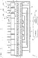
Figure 1 is a functional scheme of a machine according to the present invention, with parts removed for clarity; -
Figure 2 is a block diagram of a portion of the machine ofFigure 1 , with parts removed for clarity; -
Figures 3 to 5 are respective flow charts relating to operations performed by the control method and system according to the present invention; and -
Figures 6 to 8 are flow charts relating to the operations illustrated inFigures 3 to 5 , respectively, comprising further details on these operations. - In the following of the present description and in the claims the expression "in use" means "during operation".
-
Figure 1 schematically shows a tunnel pasteurising machine, denoted as a whole with 1, comprising acontrol system 100 and aforward movement element 21, which may consist, for example, of one or more conveyor belts or any other type of conveyor, for moving food products packaged incontainers 10 along a movement path P. -
Machine 1 comprises aheating zone 2, aheat treatment zone 3 and acooling zone 4 positioned one after another along movement path P, in order to carry out pasteurisation of the products incontainers 10. - In detail, in
heating zone 2 the temperature ofcontainers 10 is gradually raised; in heat-treatment zone 3 the temperature ofcontainers 10 is brought to, and kept at, a pasteurising temperature for a desired time interval; and incooling zone 4 the temperature ofcontainers 10 is gradually lowered to a desired output temperature. - Each one of the heating, heat treatment and
cooling zones sub-zones Figure 1 ,heating zone 2 is divided into three respective sub-zones. - Each one of the
sub-zones respective collection tank respective injection assembly processing fluid 6 from therespective collection tank containers 10 that are carried bymovement element 21. - In detail, each
tank other tanks same zone - Each
injection assembly nozzles 22 for sprayingprocessing fluid 6 ontocontainers 10. - In detail,
collection tanks processing fluid 6 after it has been sprayed on containers 10 (i.e. after it has exchanged heat with containers 10). In the shown embodiment,nozzles 22 andcollection tanks forward movement element 21, so as to exploit the gravity effect for the movement ofprocessing fluid 6. - In the following of the present description, reference will be made to heating
zone 2 only. - In particular,
collection tanks heating zone 2 are arranged in succession in such a manner thattank 5a is the upstream-most tank ofheating zone 2 andtank 5c is the downstream-most tank ofheating zone 2 according to movement path P. - In addition, the temperature of
processing fluid 6 insidetank 5b is higher than the temperature ofprocessing fluid 6 insidetank 5a; the temperature ofprocessing fluid 6 insidetank 5c is higher than the temperature ofprocessing fluid 6 insidetank 5b. -
Machine 1 further comprises aninlet valve 8 for the inlet of a fresh processing fluid 9 fromoutside machine 1. - In detail, fresh processing fluid 9 is a processing fluid that has not yet been inlet and processed in
machine 1. - Preferably, processing
fluid 6 and fresh processing fluid 9 differ only in terms of physical-biochemical properties, such as temperature and/or pH. - Furthermore, the physical-biochemical properties of fresh processing fluid 9 approximate those of
processing fluid 6 after a given number of operating hours ofmachine 1. - In the embodiment shown, fresh processing fluid 9 has a lower temperature than
processing fluid 6. - In detail,
inlet valve 8 is controllable in an open configuration, in which it allows the inlet of fresh processing fluid 9, or in a closed configuration, in which it prevents fresh processing fluid 9 from being inlet insidemachine 1. - In detail,
inlet valve 8 is adapted to allow the injection of fresh processing fluid 9 directly in theupstream-most collection tank 5a according to movement path P (Figure 1 ). -
Heating zone 2 further comprises: - a
temperature sensor 12, which is adapted to detect a temperature t ofprocessing fluid 6; and - a
level sensor 13, which is adapted to detect a level l ofprocessing fluid 6 inside one ofcollection tanks - In the embodiment shown,
level sensor 13 is a level probe. - Preferably, temperature t is the temperature of
processing fluid 6 inside one ofcollection tanks - In the embodiment shown,
temperature sensor 12 is arranged atupstream-most tank 5a and, therefore, temperature t is the temperature ofprocessing fluid 6 insideupstream-most tank 5a. -
Heating zone 2 further comprises adrainage valve 14, which is controllable in an open configuration, in which it allows the drainage of at least part ofprocessing fluid 6 from onecollection tank processing fluid 6 from said onecollection tank - Preferably,
level sensor 13 is arranged in thesame collection tank drainage valve 14 allows or prevents the drainage ofprocessing fluid 6. - In the embodiment shown,
drainage valve 14 is adapted to allow or prevent the drainage ofprocessing fluid 6 from thedownstream-most tank 5c according to movement path P (figure 1 ). - Furthermore,
control system 100 ofmachine 1 comprises acontrol unit 11, which is operatively connected totemperature sensor 12 and level sensor 13 (Figure 2 ). - Advantageously,
control unit 11 is configured to setdrainage valve 14 in the open configuration if temperature t is outside a desired temperature range and level l is within a desired level range; and to setinlet valve 8 in the open configuration if temperature t is outside the desired temperature range and level l is outside the desired level range (Figures 3 and6 ). - Preferably,
control unit 11 is configured to setdrainage valve 14 in the closed configuration wheninlet valve 8 is in the open configuration. -
Control system 100 further comprises amemory 23 configured to store the desired temperature range and the desired level range, with their respective upper and lower thresholds.Memory 23 is operatively connected to control unit 11 (Figures 1 and2 ). - In detail,
control unit 11 is configured to setdrainage valve 14 in the open configuration if temperature t is higher than an upper threshold t* of the desired temperature range and level l is higher than a lower threshold l* of the desired level range (Figure 3 ). Preferably, ifdrainage valve 14 is set in the open configuration,control unit 11 is configured to keepdrainage valve 14 in such configuration as long as temperature t is higher than upper threshold t* and until level l is lower than lower threshold l* (Figure 6 ) . - Moreover,
control unit 11 is configured to setinlet valve 8 in the open configuration if temperature t is higher than the upper threshold t* of the desired temperature range and level l is lower than the lower threshold l* of the desired level range (Figure 3 ). Preferably, ifinlet valve 8 is set in the open configuration,control unit 11 is configured to keepinlet valve 8 in such open configuration as long as temperature t is higher than upper threshold t* and until level l is greater than an hysteresis level threshold l** of the desired level range (Figure 6 ), which is greater than lower threshold l* but lower than an upper threshold l*** of the desired level range. In particular, upper threshold l*** corresponds to the maximum amount of processingfluid 6 that can be stored intank 5c without overflowing. - In addition, even more preferably,
control unit 11 is configured to setdrainage valve 14 in the open configuration only if level l is greater than hysteresis level threshold l** (Figure 6 ). As a consequence, if temperature t is higher than the upper threshold t* and level l is higher than lower threshold l* but lower than hysteresis level threshold l**,control unit 11 is configured to keepdrainage valve 14 in the closed configuration and to setinlet valve 8 in the open configuration. Also in this case,control unit 11 is preferably configured to keepinlet valve 8 in the open configuration as long as temperature t is higher than upper threshold t* and until level l is greater than hysteresis level threshold l** (Figure 6 ). - Hysteresis level threshold l** is chosen so as to avoid a rapid and repeated switching of
drainage valve 14 andinlet valve 8 between the respective open and closed configurations, which could damage the valves. - In particular,
memory 23 is further configured to store the hysteresis level threshold l** of the desired level range. - Alternatively or in addition,
control unit 11 is configured to setdrainage valve 14 in the open configuration only if a predetermined amount of time has passed sincedrainage valve 14 was set in the closed configuration. -
Heating zone 2 further comprises abiochemical quality detector 15, which is adapted to detect a biochemical quality indicator k of processingfluid 6. - In detail, biochemical quality indicator k may be pH and/or a parameter of the microbial load of
processing fluid 6. Accordingly,biochemical quality detector 15 may be a pH meter and/or a microbial load analyzer. - Preferably,
biochemical quality detector 15 is arranged inside one oftanks Figure 1 ). -
Biochemical quality detector 15 is operatively connected to control unit 11 (Figure 2 ). - In particular,
memory 23 is further configured to store a desired biochemical quality range Δk andcontrol unit 11 is configured to compare biochemical quality indicator k detected bybiochemical quality detector 15 with the desired biochemical quality range Δk. - Advantageously,
control unit 11 is configured to setdrainage valve 14 in the open configuration if biochemical quality indicator k is outside desired biochemical quality range Δk and level l is within the desired level range; and to setinlet valve 8 in the open configuration if biochemical quality indicator k is outside the desired biochemical quality range Δk and level l is outside the desired level range (Figures 4 and7 ). - In detail,
control unit 11 is configured to setdrainage valve 14 in the open configuration and to subsequently setinlet valve 8 in the open configuration if biochemical quality indicator k is outside desired biochemical quality range Δk and level l is higher than the lower threshold l* of the desired level range (Figure 4 ). - Preferably, if
drainage valve 14 is set in the open configuration,control unit 11 is configured to keepdrainage valve 14 in such open configuration until level l is lower than lower threshold l* (Figure 7 ). - In addition, if
inlet valve 8 is set in the open configuration,control unit 11 is configured to keepinlet valve 8 in such open configuration as long as biochemical quality indicator k is outside desired biochemical quality range Δk and until level l is greater than hysteresis level threshold l** (Figure 7 ). - Moreover,
control unit 11 is configured to setinlet valve 8 in the open configuration if biochemical quality indicator k is outside desired biochemical quality range Δk and level l is lower than the lower threshold l* of the desired level range (Figure 4 ). - In addition, even more preferably,
control unit 11 is configured to setdrainage valve 14 in the open configuration only if level l is greater than hysteresis level threshold l** (Figure 7 ). - As a consequence, if biochemical quality indicator k is outside desired biochemical quality range Δk and level l is higher than lower threshold l* but lower than hysteresis level threshold l**,
control unit 11 is configured to keepdrainage valve 14 in the closed configuration and to setinlet valve 8 in the open configuration as long as biochemical quality indicator k is outside desired biochemical quality range Δk and until level l is greater than hysteresis level threshold l**. - Alternatively or in addition,
control unit 11 is configured to setdrainage valve 14 in the open configuration only if a predetermined amount of time has passed sincedrainage valve 14 was set in the closed configuration. - With reference to the embodiment of
Figures 5 and8 ,control unit 11 is configured to setdrainage valve 14 in the open configuration and to subsequently setinlet valve 8 in the open configuration if temperature t is within the desired temperature range, biochemical quality indicator k is outside desired biochemical quality range Δk and level l is within the desired level range. - In detail,
control unit 11 is configured to setdrainage valve 14 in the open configuration and to subsequently setinlet valve 8 in the open configuration if temperature t is within the desired temperature range, biochemical quality indicator k is outside desired biochemical quality range Δk and level l is higher than the lower threshold l* of the desired level range (Figure 5 ). - Preferably, if
drainage valve 14 is set in the open configuration,control unit 11 is configured to keepdrainage valve 14 in such open configuration until level l is lower than lower threshold l* (Figure 8 ).Furthermore,control unit 11 is also configured to setinlet valve 8 in the open configuration if temperature t is within the desired temperature range, biochemical quality indicator k is outside desired biochemical quality range Δk and level l is outside the desired level range (Figures 5 and8 ). - In detail,
control unit 11 is configured to setinlet valve 8 in the open configuration if temperature t is within the desired temperature range, biochemical quality indicator k is outside desired biochemical quality range Δk and level l is lower than the lower threshold l* of the desired level range (Figure 5 ). - Preferably, if
inlet valve 8 is set in the open configuration,control unit 11 is configured to keepinlet valve 8 in such open configuration as long as biochemical quality indicator k is outside desired biochemical quality range Δk and until level l is greater than hysteresis level threshold l** (Figure 8 ). - In addition, even more preferably,
control unit 11 is configured to setdrainage valve 14 in the open configuration only if level l is greater than hysteresis level threshold l** (Figure 8 ). - As a consequence, if biochemical quality indicator k is outside desired biochemical quality range Δk and level l is higher than lower threshold l* but lower than hysteresis level threshold l**,
control unit 11 is configured to keepdrainage valve 14 in the closed configuration and to setinlet valve 8 in the open configuration as long as biochemical quality indicator k is outside desired biochemical quality range Δk and until level l is greater than hysteresis level threshold l**. - Alternatively or in addition,
control unit 11 is configured to setdrainage valve 14 in the open configuration only if a predetermined amount of time has passed sincedrainage valve 14 was set in the closed configuration. - In use,
machine 1 performs periodically (e.g. every two seconds) the determination of temperature t of processingfluid 6 and/or ofcontainers 10 output from cooling zone 4 (step 30) and the comparison between the determined temperature t and the desired temperature range by means of control unit 11 (step 31) (Figures 3 and6 ). In this condition, bothinlet valve 8 anddrainage valve 14 are in their respective closed configurations. - If temperature t is outside the desired temperature range,
machine 1 performs the detection of level l of processingfluid 6 insidetank 5c by means of level sensor 13 (step 32) and the comparison between the detected level l and the desired level range by means of control unit 11 (step 33) (Figures 3 and6 ). - In detail, if temperature t is higher than the upper threshold t* of the desired temperature range and level l is higher than the lower threshold l* of the desired level range,
control unit 11 setsdrainage valve 14 in the open configuration, so as to discharge at least part of processing fluid 6 fromtank 5c (step 34 ofFigure 3 ). - As a consequence, some
processing fluid 6 moves fromtanks tank 5c, by virtue of the principle of the communicating vessels. In detail, processingfluid 6 insidetank 5c mixes with someprocessing fluid 6 fromtanks 5b and/or 5a andprocessing fluid 6 insidetank 5b mixes with someprocessing fluid 6 fromtank 5a. - Since the temperature of processing
fluid 6 is higher insidetank 5b thaninside tank 5a and the temperature of processingfluid 6 is higher insidetank 5c thaninside tank 5b, this may be sufficient to bring temperature t within the desired temperature range (i.e. below upper threshold t*). Otherwise, temperature t will still be detected outside the desired temperature range. - Preferably,
inlet valve 8 is set in the closed configuration whendrainage valve 14 is in the open configuration. - Preferably, once
drainage valve 14 is set in the open configuration,control unit 11 keepsdrainage valve 14 in such open configuration as long as temperature t is higher than upper threshold t* and until level l is lower than lower threshold l* (step 34 ofFigure 6 ). In other words, if temperature t becomes lower than upper threshold t* while processingfluid 6 is discharged fromdrainage valve 14,control unit 11 setsdrainage valve 14 back in the closed configuration, even if level l is higher than lower threshold l*. This is possible becausemachine 1 performs periodically the determination of temperature t and the comparison of the determined temperature with the desired temperature range and the detection of level l and the comparison of the detected level l with the desired level range. - If, on the contrary, temperature t is higher than the upper threshold t* of the desired temperature range and level l is lower than the lower threshold l* of the desired level range,
control unit 11 setsinlet valve 8 in the open configuration, so as to allow the injection of fresh processing fluid 9 directly intank 5a (step 35 ofFigure 3 ) . - Preferably,
drainage valve 14 is set in the closed configuration wheninlet valve 8 is in the open configuration. - In addition, once
inlet valve 8 is set in the open configuration,control unit 11 preferably keepsinlet valve 8 in such open configuration as long as temperature t is higher than upper threshold t* and until level l is greater than hysteresis level threshold l** of the desired level range (step 35 ofFigure 6 ). In other words, if temperature t becomes lower than upper threshold t*,control unit 11 setsinlet valve 8 back in the closed configuration, even if level l is lower than hysteresis level threshold l**. - In addition, preferably,
control unit 11 setsdrainage valve 14 in the open configuration only if level l is greater than hysteresis level threshold l** (step 33 ofFigure 6 ). - As a consequence, if temperature t is higher than the upper threshold t* and level l is higher than lower threshold l* but lower than hysteresis level threshold l**,
control unit 11 keepsdrainage valve 14 in the closed configuration and setsinlet valve 8 in the open configuration as long as temperature t is higher than upper threshold t* and until level l is greater than hysteresis level threshold l**. Therefore, if temperature t becomes lower than upper threshold t* while fresh processing fluid 9 is injectedtrough inlet valve 8,control unit 11 setsinlet valve 8 back in the closed configuration, even if level l is lower than hysteresis level threshold l**. - Alternatively or in addition,
control unit 11 setsdrainage valve 14 in the open configuration only if a predetermined amount of time has passed sincedrainage valve 14 was set in the closed configuration. - In one embodiment,
machine 1 detects periodically (e.g. every two seconds) level l of theprocessing fluid 6 insidetank 5c (step 32) independently of the determination of temperature t (step 30). -
Machine 1 also performs periodically (e.g. every 5 minutes) the detection of biochemical quality indicator k of processingfluid 6 by means of biochemical quality detector 15 (step 36) and the comparison between the detected biochemical quality indicator k and the desired biochemical quality range Δk by means of control unit 11 (step 37) (Figures 4 and7 ) . - In detail, the detection of biochemical quality indicator k (step 36) may be carried out independently of the determination of temperature t (step 30).
- If the detected biochemical quality indicator k is outside the desired biochemical quality range Δk,
machine 1 performs the detection of level l insidetank 5c by means of level sensor 13 (step 32) and the comparison between the detected level l and the desired level range by means of control unit 11 (step 33) (Figures 4 and7 ). - In detail, if biochemical quality indicator k is outside the desired biochemical quality range Δk and level l is higher than the lower threshold l* of the desired level range,
control unit 11 controlsdrainage valve 14 in the open configuration, so as to discharge at least part of processing fluid 6 fromtank 5c (step 34 ofFigure 4 ). - Preferably, once
drainage valve 14 is set in the open configuration,control unit 11 keepsdrainage valve 14 in such open configuration until level l is lower than lower threshold l* (step 34 ofFigure 7 ). - Subsequently,
control unit 11controls inlet valve 8 in the open configuration, so as to allow the injection of fresh processing fluid 9 directly intank 5a (step 35 ofFigures 4 and7 ). - Preferably, once
inlet valve 8 is set in the open configuration,control unit 11 keepsinlet valve 8 in such open configuration as long as biochemical quality indicator k is outside desired biochemical quality range Δk and until level l is greater than hysteresis level threshold l**, which is greater than lower threshold l* (step 35 ofFigure 7 ). In other words, if biochemical quality indicator k moves within desired biochemical quality range Δk while fresh processing fluid 9 is injectedtrough inlet valve 8,control unit 11 setsinlet valve 8 back in the closed configuration, even iflevel 1 is lower than hysteresis level threshold l**. - If, on the contrary, biochemical quality indicator k is outside the desired biochemical quality range Δk and level l is lower than the lower threshold l* of the desired level range,
control unit 11controls inlet valve 8 in the open configuration, so as to allow the injection of fresh processing fluid 9 directly intank 5a (step 35 ofFigure 4 ) . - In addition, even more preferably,
control unit 11 setsdrainage valve 14 in the open configuration only if level l is greater than hysteresis level threshold l** (step 33 ofFigure 7 ). - As a consequence, if biochemical quality indicator k is outside desired biochemical quality range Δk and level l is higher than lower threshold l* but lower than hysteresis level threshold l**,
control unit 11 is configured to keepdrainage valve 14 in the closed configuration and to setinlet valve 8 in the open configuration as long as biochemical quality indicator k is outside desired biochemical quality range Δk and until level l is greater than hysteresis level threshold l**. Therefore, if biochemical quality indicator k moves within desired biochemical quality range Δk while fresh processing fluid 9 is injected throughinlet valve 8,control unit 11 setsinlet valve 8 back in the closed configuration, even if level l is lower than hysteresis level threshold l**. - Alternatively or in addition,
control unit 11 setsdrainage valve 14 in the open configuration only if a predetermined amount of time has passed sincedrainage valve 14 was set in the closed configuration. - In the embodiment shown in
Figures 5 and8 ,machine 1 also performs the detection of biochemical quality indicator k of processing fluid 6 (step 36) and the comparison between the detected biochemical quality indicator k and the desired biochemical quality range Δk (step 37) everytime machine 1 performs the determination of temperature t (step 30). - Preferably, in the embodiment shown in
Figures 5 and8 , the detection of biochemical quality indicator k (step 36) is carried out after the determination of temperature t (step 30) and the comparison between temperature t and the desired temperature range (step 31). Even more preferably, the detection of biochemical quality indicator k (step 36) is carried out if temperature t is within the desired temperature range (step 31) (Figures 5 and8 ). - In detail, if temperature t is within the desired temperature range (step 31), biochemical quality indicator k is outside desired biochemical quality range Δk and level l is higher than the lower threshold l* of the desired level range,
control unit 11 controlsdrainage valve 14 in the open configuration, so as to discharge at least part of processing fluid 6 fromtank 5c (step 34 ofFigure 5 ). - Preferably, once
drainage valve 14 is set in the open configuration,control unit 11 keepsdrainage valve 14 in such open configuration until level l is lower than lower threshold l* (step 34 ofFigure 8 ). - Subsequently,
control unit 11controls inlet valve 8 in the open configuration, so as to allow the injection of fresh processing fluid 9 directly intank 5a (step 35 ofFigures 5 and8 ). - If, on the contrary, temperature t is within the desired temperature range (step 31), biochemical quality indicator k is outside the desired biochemical quality range Δk and level l is lower than the lower threshold l* of the desired level range,
control unit 11controls inlet valve 8 in the open configuration, so as to allow the injection of fresh processing fluid 9 directly intank 5a (step 35) (Figure 5 ). - Preferably, once
inlet valve 8 is set in the open configuration,control unit 11 keepsinlet valve 8 in such open configuration as long as biochemical quality indicator k is outside desired biochemical quality range Δk and until level l is greater than hysteresis level threshold l** (step 35 ofFigure 8 ). In other words, if biochemical quality indicator k moves within desired biochemical quality range Δk while fresh processing fluid 9 is injected throughinlet valve 8,control unit 11 setsinlet valve 8 back in the closed configuration, even if level l is lower than hysteresis level threshold l**. - In addition, preferably,
control unit 11 setsdrainage valve 14 in the open configuration only if level l is greater than hysteresis level threshold l** (step 33 ofFigure 8 ). - As a consequence, if biochemical quality indicator k is outside the desired biochemical quality range Δk and level l is higher than lower threshold l* but lower than hysteresis level threshold l**,
control unit 11 keepsdrainage valve 14 in the closed configuration and setsinlet valve 8 in the open configuration as long as biochemical quality indicator k is outside the desired biochemical quality range Δk and until level l is greater than hysteresis level threshold l**. In other words, if biochemical quality indicator k moves within desired biochemical quality range Δk while fresh processing fluid 9 is injected throughinlet valve 8,control unit 11 setsinlet valve 8 back in the closed configuration, even if level l is lower than hysteresis level threshold l**. - Alternatively or in addition,
control unit 11 setsdrainage valve 14 in the open configuration only if a predetermined amount of time has passed sincedrainage valve 14 was set in the closed configuration. - The advantages of the control method,
control system 100 and method for retrofitting according to the present invention will be clear from the above description. - In particular, since
control unit 11 is configured to controldrainage valve 14 to discharge at least part of processing fluid 6 fromtank 5c, it is possible to control temperature t in an efficient manner, while minimizing the waste ofprocessing fluid 6. - In fact, before injecting fresh processing fluid 9 in
tank 5a, someprocessing fluid 6 is drained throughdrainage valve 14, if the detected level l is higher than the lower threshold l* or the hysteresis level threshold l** of the desired level range. In this case, the mass and the thermal inertia of processingfluid 6 insidetanks - Furthermore, since the drainage of
processing fluid 6 is carried out before the injection of fresh processing fluid 9 if the detected level l is higher than the lower threshold l*, the biochemical quality ofprocessing fluid 6 is improved. In fact, the fresh processing fluid 9 injected after the drainage mixes withprocessing fluid 6 having a lower mass than before the drainage. - In addition, since the drainage of
processing fluid 6 and the injection of fresh processing fluid 9 may be carried out also on the basis of the detected biochemical quality indicator k, the biochemical quality ofprocessing fluid 6 can be even more accurately controlled during the operation ofmachine 1. In detail, the detection of biochemical quality indicator k may be carried out in concomitance with the determination of temperature t or independently of it (e.g. periodically). - Furthermore, since the drainage of
processing fluid 6 and/or the injection of fresh processing fluid 9 may be carried out as soon as the biochemical quality indicator k is outside the desired biochemical quality range Δk, the complete substitution ofprocessing fluid 6 with fresh processing fluid 9 is required very infrequently or not at all. - The Applicant has also observed that when
drainage valve 14 is adapted to allow or prevent the drainage of processing fluid 6 from thedownstream-most tank 5c, the reduction of temperature t is particularly efficient. - In fact, when some fluid is discharged from
tank 5c, processingfluid 6 insidetank 5c mixes with someprocessing fluid 6 fromtanks 5b and/or 5a andprocessing fluid 6 insidetank 5b mixes with someprocessing fluid 6 fromtank 5a. - Since the temperature of processing
fluid 6 is higher insidetank 5b thaninside tank 5a and the temperature of processingfluid 6 is higher insidetank 5c thaninside tank 5b, this may be sufficient to bring temperature t within the desired temperature range (i.e. below upper threshold t*). Otherwise, temperature t will still be detected to be outside the desired temperature range. - The reduction of temperature t is even more efficient when
inlet valve 8 injects fresh processing fluid 9 directly in theupstream-most collection tank 5a. - The discussed solution may also be easily fitted (with a so called "retrofit" operation) to existing machines, by: arranging
inlet valve 8 atmachine 1, preferably so as to be adapted to inject fresh processing fluid 9 directly incollection tank 5a; arrangingtemperature sensor 12 and/orbiochemical quality detector 15 atheating zone 2; arranginglevel sensor 13 incollection tank drainage valve 14 incollection tank collection tank 5c; operatively connectinglevel sensor 13,temperature sensor 12 and/orbiochemical quality detector 15 to controlunit 11; configuringcontrol unit 11 to setdrainage valve 14 in the open configuration if temperature t is outside the desired temperature range and/or biochemical quality indicator k is outside the desired biochemical quality range and level l is within the desired level range; and configuringcontrol unit 11 to setinlet valve 8 in the open configuration if temperature t is outside the desired temperature range and/or biochemical quality indicator k is outside the desired biochemical quality range and level l is outside the desired level range. - Furthermore, since
control unit 11 is preferably configured to keepinlet valve 8 in the open configuration as long as temperature t is higher than upper threshold t* and until level l is greater than hysteresis level threshold l** andcontrol unit 11 is configured to setdrainage valve 14 in the open configuration only if level l is greater than hysteresis level threshold l**, damage todrainage valve 14 andinlet valve 8 caused by the rapid switching between the respective open and closed configurations is avoided. - Since alternatively or in addition,
control unit 11 is configured to setdrainage valve 14 in the open configuration only if a predetermined amount of time has passed sincedrainage valve 14 was set in the closed configuration, damage todrainage valve 14 andinlet valve 8 is even less likely. - Finally, it is apparent that modifications and variants not departing from the scope of protection of the claims may be made to control method and system according to the present invention.
- In particular, the claimed control method and system may be applied also to
heat treatment zone 3 or to coolingzone 4. - In addition,
machine 1 may comprise more than oneinlet valve 8 and/or more than onedrainage valve 14. For example,machine 1 may comprise aninlet valve 8 and/or adrainage valve 14 for eachcollection tank - Furthermore,
heating zone 2 may comprise a plurality oftemperature sensors 12, each arranged at arespective collection tank control unit 11 may be operatively connected to the plurality oftemperature sensors 12 and configured to compare the temperature detected by each of thetemperature sensors 12 with a respective desired temperature range. - Similarly,
heating zone 2 may comprise a plurality ofbiochemical quality detectors 15, each arranged at arespective collection tank control unit 11 may be operatively connected to the plurality ofbiochemical quality detectors 15 and configured to compare the biochemical quality indicator k detected by each of thebiochemical quality detectors 15 with a respective desired biochemical quality range.
Claims (19)
- A control method for controlling a machine (1) for the temperature processing of containers (10) of food products; said machine (1) comprising a control unit (11) and at least one temperature-processing zone (2, 3, 4), where the containers (10) are processed by injecting a processing fluid (6) on them; the temperature-processing zone (2, 3, 4) comprising, in turn:- at least one collection tank (5a, 5b, 5c) for storing said processing fluid (6); and- an injection assembly (7a, 7b, 7c) for injecting said processing fluid (6) from said at least one collection tank (5a, 5b, 5c) onto said containers (10);said method being characterized by comprising the steps of:i) determining a temperature (t) of said processing fluid (6) by means of a temperature sensor (12) of said machine (1) and/or a temperature (t) of said containers (10);ii) comparing the temperature (t) determined at said step i) with a desired temperature range by means of said control unit (11);iii) detecting a level (l) of said processing fluid (6) inside said at least one collection tank (5a, 5b, 5c) by means of a level sensor (13) of said machine (1);iv) comparing the level (l) detected at said step iii) with a desired level range by means of said control unit (11);v) controlling by means of said control unit (11) a drainage valve (14) of said at least one collection tank (5a, 5b, 5c) to discharge at least part of the processing fluid (6) from said at least one collection tank (5a, 5b, 5c), if the temperature (t) determined at step i) is outside said desired temperature range and the level (l) detected at step iii) is within said desired level range; andvi) controlling by means of said control unit (11) an inlet valve (8) of said machine (1) to allow the injection of fresh processing fluid (9) from outside said machine (1) in said at least one collection tank (5a, 5b, 5c), if the temperature (t) determined at step i) is outside said desired temperature range and the level (l) detected at step iii) is outside said desired level range.
- The control method according to claim 1, characterized in that during said step v) said control unit (11) controls said drainage valve (14) to discharge at least part of the processing fluid (6) from said at least one collection tank (5a, 5b, 5c), if the temperature (t) determined at step i) is higher than an upper temperature threshold (t*) of said desired temperature range and the level (l) detected at step iii) is higher than a lower level threshold (l*; l**) of said desired level range; and in that during said step vi) said control unit (11) controls said inlet valve (8) to allow the injection of fresh processing fluid (9) from outside said machine (1) in said at least one collection tank (5a, 5b, 5c), if the temperature (t) determined at step i) is higher than said upper temperature threshold (t*) and the level (l) detected at step iii) is lower than said lower level threshold (l*; l**).
- The control method according to claim 2, characterized in that during said step v) said control unit (11) controls said drainage valve (14) to discharge at least part of the processing fluid (6) from said at least one collection tank (5a, 5b, 5c), if the temperature (t) determined at step i) is higher than said upper temperature threshold (t*) of said desired temperature range and the level (l) detected at step iii) is higher than an hysteresis level threshold (l**) of said desired level range; said hysteresis level threshold (l**) being greater than said lower level threshold (l*); and in that during said step vi) said control unit (11) controls said inlet valve (8) to allow the injection of fresh processing fluid (9) from outside said machine (1) in said at least one collection tank (5a, 5b, 5c) if the temperature (t) determined at step i) is higher than said upper temperature threshold (t*) of said desired temperature range and the level (l) detected at step iii) is lower than said hysteresis level threshold (l**).
- The control method according to claim 3, characterized in said step v) comprises the step vii) of controlling said drainage valve (14) by means of said control unit (11) to discharge the processing fluid (6) from said at least one collection tank (5a, 5b, 5c) until said level (l) is lower than said lower level threshold (l*); and in that said step vi) comprises the step viii) of controlling said inlet valve (8) by means of said control unit (11) to allow the injection of fresh processing fluid (9) from outside said machine (1) in said at least one collection tank (5a, 5b, 5c) until said level (l) is higher than said hysteresis level threshold (l**).
- The control method according to claim 4, characterized by comprising the further steps of:ix) preventing by means of said control unit (11) said drainage valve (14) from discharging processing fluid (6) from said at least one collection tank (5a, 5b, 5c), if during said step vii) said temperature (t) of said processing fluid (6) and/or said temperature (t) of said containers (10) becomes lower than said upper temperature threshold (t*) ;x) preventing by means of said control unit (11) said inlet valve (8) from allowing the injection of fresh processing fluid (9) in said at least one collection tank (5a, 5b, 5c), if during said step viii) said temperature (t) of said processing fluid (6) and/or said temperature (t) of said containers (10) becomes lower than said upper temperature threshold (t*).
- The control method according to claims 1 to 5, characterized in that said step v) comprises the further step xi) of controlling by means of said control unit (11) a drainage valve (14) of a downstream-most collection tank (5c) of said temperature-processing zone (2, 3, 4) according to a movement path (P) of said containers (1) along said machine (1), to discharge at least part of the processing fluid (6) from said downstream-most collection tank (5c); said temperature-processing zone (2, 3, 4) comprising a plurality of said collection tanks (5a, 5b, 5c), each being in fluidic communication with the other tanks (5a, 5b, 5c) of the same temperature-processing zone (2, 3, 4).
- The control method according to claim 6, characterized in that said step vi) comprises the further step xii) of controlling by means of said control unit (11) said inlet valve (8) to allow the injection of fresh processing fluid (9) directly in an upstream-most collection tank (5a) of said temperature-processing zone (2, 3, 4) according to said movement path (P).
- The control method according to any one of the foregoing claims, characterized by comprising the further steps of:xiii) detecting a biochemical quality indicator (k) of said processing fluid (6) by means of a biochemical quality detector (15) of said machine (1); andxiv) comparing the biochemical quality indicator (k) detected at said step xiii) with a desired biochemical quality range (Δk) by means of said control unit (11);xv) controlling by means of said control unit (11) said drainage valve (14) to discharge at least part of the processing fluid (6) from said at least one collection tank (5a, 5b, 5c), if the biochemical quality indicator (k) detected at step xiii) is outside said desired biochemical quality range (Δk) and the level (l) detected at step iii) is within said desired level range; and subsequently controlling by means of said control unit (11) said inlet valve (8) to allow the injection of fresh processing fluid (9) in said at least one collection tank (5a, 5b, 5c); andxvi) controlling by means of said control unit (11) said inlet valve (8) to allow the injection of fresh processing fluid (9) in said at least one collection tank (5a, 5b, 5c), if the biochemical quality indicator (k) detected at step xiii) is outside said desired biochemical quality range (Δk) and the level (l) detected at step iii) is outside said desired level range.
- The control method according to claim 8, characterized in that said steps xv) and xvi) are carried out if the temperature (t) determined at step i) is within said desired temperature range.
- Method for retrofitting a machine (1) for the temperature processing of containers (10) for food products; said machine (1) comprising at least one temperature-processing zone (2, 3, 4), where the containers (10) are processed by injecting a processing fluid (6) on them; said temperature processing-zone (2, 3, 4) comprising:- at least one collection tank (5a, 5b, 5c) for storing said processing fluid (6); and- an injection assembly (7a, 7b, 7c) for injecting said processing fluid (6) from said at least one collection tank (5a, 5b, 5c) onto said containers (10);
said method being characterized by comprising the steps of:xvii) arranging at said machine (1) an inlet valve (8) controllable in an open configuration, in which it allows the inlet of fresh processing fluid (9) from outside said machine (1), or in a closed configuration, in which it prevents fresh processing fluid (9) from being inlet inside said machine (1);xviii) arranging at said temperature processing-zone (2, 3, 4) a temperature sensor (12) adapted to detect a temperature (t) of the processing fluid (6);xix) arranging inside said at least one collection tank (5a, 5b, 5c) a level sensor (13) adapted to detect a level (l) of the processing fluid (6) inside said at least one collection tank (5a, 5b, 5c);xx) arranging at said at least one collection tank (5a, 5b, 5c) a drainage valve (14), which is controllable in an open configuration, in which it allows the drainage of at least part of the processing fluid (6) from said at least one collection tank (5a, 5b, 5c), or in a closed configuration, in which it prevents the drainage of the processing fluid (6) from said at least one collection tank (5a, 5b, 5c);xxi) operatively connecting said temperature sensor (12) and said level sensor (13) to a control unit (11) of said machine (1);xxii) configuring said control unit (11) to set said drainage valve (14) in the open configuration if the temperature (t) of the processing fluid (6) and/or a temperature (t) of said containers (10) is outside a desired temperature range and said level (l) is within a desired level range; and configuring said control unit (11) to set said inlet valve (8) in said open configuration if the temperature (t) of the processing fluid (6) and/or the temperature (t) of said containers (10) is outside said desired temperature range and said level (l) is outside said desired level range. - A control method for controlling a machine (1) for the temperature processing of containers (10) of food products; said machine (1) comprising a control unit (11), at least one temperature-processing zone (2, 3, 4), where the containers (10) are processed by injecting a processing fluid (6) on them; the temperature-processing zone (2, 3, 4) comprising, in turn:- at least one collection tank (5a, 5b, 5c) for storing said processing fluid (6); and- an injection assembly (7a, 7b, 7c) for injecting said processing fluid (6) from said at least one collection tank (5a, 5b, 5c) onto said containers (10);said method being characterized by comprising the steps of:i) detecting a biochemical quality indicator (k) of said processing fluid (6) by means of a biochemical quality detector (15) of said machine (1);ii) comparing the biochemical quality indicator (k) detected at said step i) with a desired biochemical quality range (Δk) by means of said control unit (11);iii) detecting a level (l) of said processing fluid (6) inside said at least one collection tank (5a, 5b, 5c) by means of a level sensor (13) of said machine (1);iv) comparing the level (l) detected at said step iii) with a desired level range by means of said control unit (11) ;v) controlling by means of said control unit (11) a drainage valve (14) of said at least one collection tank (5a, 5b, 5c) to discharge at least part of the processing fluid (6) from said at least one collection tank (5a, 5b, 5c), if the biochemical quality indicator (k) detected at step i) is outside said desired biochemical quality range (Δk) and the level (l) detected at step iii) is within said desired level range; and subsequently controlling by means of said control unit (11) an inlet valve (8) of said machine (1) to allow the injection of fresh processing fluid (9) from outside said machine (1) in said at least one collection tank (5a, 5b, 5c); andvi) controlling by means of said control unit (11) an inlet valve (8) of said machine (1) to allow the injection of fresh processing fluid (9) from outside said machine (1) in said at least one collection tank (5a, 5b, 5c), if the biochemical quality indicator (k) detected at step i) is outside said desired biochemical quality range (Δk) and the level (l) detected at step iii) is outside said desired level range.
- A control system (100) for controlling a machine (1) for the temperature processing of containers (10) of food products; said machine (1) comprising at least one temperature-processing zone (2, 3, 4), where containers (10) are processed by injecting a processing fluid (6) on them; said temperature-processing zone (2, 3, 4) comprising, in turn:- at least one collection tank (5a, 5b, 5c) for storing said processing fluid (6);- an injection assembly (7a, 7b, 7c) for injecting said processing fluid (6) from said at least one collection tank (5a, 5b, 5c) onto said containers (10); and- an inlet valve (8) controllable in an open configuration, in which it allows the inlet of a fresh processing fluid (9) from outside said machine (1), or in a closed configuration, in which it prevents fresh processing fluid (9) from being inlet inside said machine (1);said temperature-processing zone (2, 3, 4) further comprising:- a temperature sensor (12) adapted to detect a temperature (t) of said processing fluid (6);- a level sensor (13) adapted to detect a level (l) of the processing fluid (6) inside said at least one collection tank (5a, 5b, 5c); and- a drainage valve (14) controllable in an open configuration, in which it allows the drainage of at least part of the processing fluid (6) from said at least one collection tank (5a, 5b, 5c), or in a closed configuration, in which it prevents the drainage of the processing fluid (6) from said at least one collection tank (5a, 5b, 5c);said control system (100) comprising a control unit (11) operatively connected to said machine (1);
said control unit (11) being configured to compare the temperature (t) determined by said temperature sensor (12) and/or a temperature (t) of said containers (10) with a desired temperature range and compare the level (l) detected by said level sensor (13) with a desired level range;
characterized in that said control unit (11) is configured to set, in use, said drainage valve (14) in said open configuration if the temperature (t) of the processing fluid (6) and/or the temperature (t) of said containers (10) is outside said desired temperature range and the level (l) is within said desired level range;
said control unit (11) being further configured to set, in use, said inlet valve (8) in said open configuration if the temperature (t) of the processing fluid (6) and/or the temperature (t) of said containers (10) is outside said desired temperature range and the level (l) is outside said desired level range. - The control system according to claim 12 characterized in that said control unit (11) is configured to set, in use, said drainage valve (14) in said open configuration if the temperature (t) of the processing fluid (6) and/or the temperature (t) of said containers (10) is higher than an upper temperature threshold (t*) of said desired temperature range and the level (l) is higher than a lower level threshold (l*, l**) of said desired level range;
said control unit (11) being further configured to set, in use, said inlet valve (8) in said open configuration if the temperature (t) of the processing fluid (6) and/or the temperature (t) of said containers (10) is higher than said upper temperature threshold (t*) and the level (l) is lower than said lower level threshold (l*, l**). - The control system according to claim 13, characterized in that said control unit (11) is configured to set, in use, said drainage valve (14) in said open configuration if the temperature (t) of the processing fluid (6) and/or the temperature (t) of said containers (10) is higher than an upper temperature threshold (t*) of said desired temperature range and the level (l) is higher than an hysteresis level threshold (l**) of said desired level range; said hysteresis level threshold (l**) being greater than said lower level threshold (l*);
said control unit (11) being further configured to set, in use, said inlet valve (8) in said open configuration if the temperature (t) of the processing fluid (6) and/or the temperature (t) of said containers (10) is higher than said upper temperature threshold (t*) and the level (l) is lower than said hysteresis level threshold (l**). - The control system according to claim 14, characterized in that said control unit (11) is configured to keep said drainage valve (14) in said open configuration until, in use, said level (l) lower than said lower level threshold (l*) unless, in use, said temperature (t) of said processing fluid (6) and/or said temperature (t) of said containers (10) becomes lower than said upper temperature threshold (t*);
and in that said control unit (11) is configured to keep said inlet valve (8) in said open configuration until, in use, said level (l) is greater than said hysteresis level threshold (l**) unless, in use, said temperature (t) of said processing fluid (6) and/or said temperature (t) of said containers (10) becomes lower than said upper temperature threshold (t*). - The control system according to claims 12 to 15 wherein said temperature-processing zone (2, 3, 4) comprises a plurality of collection tanks (5a, 5b, 5c); each tank (5a, 5b, 5c) being in fluidic communication with the other tanks (5a, 5b, 5c) of the same temperature-processing zone (2, 3, 4) ;
characterized in that said control unit (11) is further configured to control said drainage valve (14) of the downstream-most collection tank (5c) of said temperature-processing zone (2, 3, 4) according to a movement path (P) of said containers (10) along said machine (1). - The control system according to claim 16, characterized in that said control unit (11) is further configured to set said inlet valve (8) in said open configuration, so as to allow the injection of fresh processing fluid (9) directly in the upstream-most collection tank (5a) of said temperature-processing zone (2, 3, 4) according to said movement path (P).
- The control system according to claims 12 to 17, wherein said temperature-processing zone (2, 3, 4) further comprises a biochemical quality detector (15), which is adapted to detect a biochemical quality indicator (k) of said processing fluid (6);
characterized in that said control unit (11) is further configured to compare, in use, said biochemical quality indicator (k) with a desired biochemical quality range (Δk). - A machine (1) for the temperature processing of containers (10) for food products comprising at least one temperature-processing zone (2, 3, 4), where the containers (10) are processed by injecting a processing fluid (6) on them; said temperature processing-zone (2, 3, 4) comprising:- at least one collection tank (5a, 5b, 5c) for storing said processing fluid (6);- an injection assembly (7a, 7b, 7c) for injecting said processing fluid (6) from said at least one collection tank (5a, 5b, 5c) onto said containers (10); and- an inlet valve (8) controllable in an open configuration, in which it allows the inlet of fresh processing fluid (9) from outside said machine (1), or in a closed configuration, in which it prevents fresh processing fluid (9) from being inlet inside said machine (1);said temperature-processing zone (2, 3, 4) further comprising:- a temperature sensor (12) adapted to detect a temperature (t) of the processing fluid (6);- a level sensor (13) adapted to detect a level of the processing fluid (6) inside said at least one collection tank (5a, 5b, 5c); and- a drainage valve (14) controllable in an open configuration, in which it allows the drainage of at least part of the processing fluid (6) from said at least one collection tank (5a, 5b, 5c), or in a closed configuration, in which it prevents the drainage of the processing fluid (6) from said at least one collection tank (5a, 5b, 5c);characterized by comprising a control system (100) according to any one of claims 12 to 18.
Priority Applications (2)
| Application Number | Priority Date | Filing Date | Title |
|---|---|---|---|
| EP20215919.0A EP4014753B1 (en) | 2020-12-21 | 2020-12-21 | Control method and system for controlling a machine for the temperature processing of containers of food products |
| PCT/EP2021/086265 WO2022136122A1 (en) | 2020-12-21 | 2021-12-16 | Control method and system for controlling a machine for the temperature processing of containers of food products; method for retrofitting such machine |
Applications Claiming Priority (1)
| Application Number | Priority Date | Filing Date | Title |
|---|---|---|---|
| EP20215919.0A EP4014753B1 (en) | 2020-12-21 | 2020-12-21 | Control method and system for controlling a machine for the temperature processing of containers of food products |
Publications (2)
| Publication Number | Publication Date |
|---|---|
| EP4014753A1 true EP4014753A1 (en) | 2022-06-22 |
| EP4014753B1 EP4014753B1 (en) | 2024-01-24 |
Family
ID=73856083
Family Applications (1)
| Application Number | Title | Priority Date | Filing Date |
|---|---|---|---|
| EP20215919.0A Active EP4014753B1 (en) | 2020-12-21 | 2020-12-21 | Control method and system for controlling a machine for the temperature processing of containers of food products |
Country Status (2)
| Country | Link |
|---|---|
| EP (1) | EP4014753B1 (en) |
| WO (1) | WO2022136122A1 (en) |
Cited By (1)
| Publication number | Priority date | Publication date | Assignee | Title |
|---|---|---|---|---|
| EP4464170A1 (en) * | 2023-05-19 | 2024-11-20 | Krones AG | Tunnel pasteurizer and method of monitoring and controlling a tunnel pasteurizer |
Families Citing this family (3)
| Publication number | Priority date | Publication date | Assignee | Title |
|---|---|---|---|---|
| DE102024113557A1 (en) * | 2024-05-15 | 2025-11-20 | Krones Aktiengesellschaft | Thermal container treatment device and method for operating the thermal container treatment device |
| EP4781829A1 (en) * | 2025-01-23 | 2026-07-29 | Sidel Participations | Double-deck pasteurizing machine with treatment liquid redirection system and related method |
| EP4781830A1 (en) * | 2025-01-23 | 2026-07-29 | Sidel Participations | Double-deck pasteurizing machine with treatment liquid redirection system and related method |
Citations (7)
| Publication number | Priority date | Publication date | Assignee | Title |
|---|---|---|---|---|
| DE3029113A1 (en) * | 1979-08-01 | 1981-02-19 | Barry Wehmiller Co | METHOD AND ARRANGEMENT FOR SAVING ENERGY IN PASTEURIZING SYSTEMS |
| US4441406A (en) * | 1982-06-14 | 1984-04-10 | Miller Brewing Company | Pasteurization apparatus |
| US4849235A (en) * | 1985-11-05 | 1989-07-18 | Societe Nouvelle Baele Gangloff | Method for pasteurizing food products in containers |
| US20020073652A1 (en) * | 2000-02-23 | 2002-06-20 | Ulrich Wiedemann | Bottling plant and method of operating a bottling plant and a bottling plant with sections for stabilizing the bottled product |
| US20090280222A1 (en) * | 2005-06-17 | 2009-11-12 | Jorgen Tage Nielsen | Tunnel pasteurizer |
| EP2702879A1 (en) | 2012-08-30 | 2014-03-05 | Sidel S.p.a. Con Socio Unico | System and method for temperature control in a temperature processing machine for food product containers |
| EP2959782A2 (en) * | 2014-06-24 | 2015-12-30 | Krones AG | Tempering system with cleaning for process fluid |
-
2020
- 2020-12-21 EP EP20215919.0A patent/EP4014753B1/en active Active
-
2021
- 2021-12-16 WO PCT/EP2021/086265 patent/WO2022136122A1/en not_active Ceased
Patent Citations (7)
| Publication number | Priority date | Publication date | Assignee | Title |
|---|---|---|---|---|
| DE3029113A1 (en) * | 1979-08-01 | 1981-02-19 | Barry Wehmiller Co | METHOD AND ARRANGEMENT FOR SAVING ENERGY IN PASTEURIZING SYSTEMS |
| US4441406A (en) * | 1982-06-14 | 1984-04-10 | Miller Brewing Company | Pasteurization apparatus |
| US4849235A (en) * | 1985-11-05 | 1989-07-18 | Societe Nouvelle Baele Gangloff | Method for pasteurizing food products in containers |
| US20020073652A1 (en) * | 2000-02-23 | 2002-06-20 | Ulrich Wiedemann | Bottling plant and method of operating a bottling plant and a bottling plant with sections for stabilizing the bottled product |
| US20090280222A1 (en) * | 2005-06-17 | 2009-11-12 | Jorgen Tage Nielsen | Tunnel pasteurizer |
| EP2702879A1 (en) | 2012-08-30 | 2014-03-05 | Sidel S.p.a. Con Socio Unico | System and method for temperature control in a temperature processing machine for food product containers |
| EP2959782A2 (en) * | 2014-06-24 | 2015-12-30 | Krones AG | Tempering system with cleaning for process fluid |
Cited By (2)
| Publication number | Priority date | Publication date | Assignee | Title |
|---|---|---|---|---|
| EP4464170A1 (en) * | 2023-05-19 | 2024-11-20 | Krones AG | Tunnel pasteurizer and method of monitoring and controlling a tunnel pasteurizer |
| CN118992245A (en) * | 2023-05-19 | 2024-11-22 | 克朗斯股份公司 | Tunnel pasteurization machine and method for monitoring and controlling tunnel pasteurization machine |
Also Published As
| Publication number | Publication date |
|---|---|
| EP4014753B1 (en) | 2024-01-24 |
| WO2022136122A1 (en) | 2022-06-30 |
Similar Documents
| Publication | Publication Date | Title |
|---|---|---|
| EP4014753B1 (en) | Control method and system for controlling a machine for the temperature processing of containers of food products | |
| US9095638B2 (en) | System and method for temperature control in a temperature processing machine for food product containers | |
| EP0744903B1 (en) | Method and apparatus for the pasteurization of a continuous line of products | |
| US20180325147A1 (en) | System and method for pasteurizing foods | |
| JP6283926B2 (en) | Sterilizer | |
| MX2008014498A (en) | Method and system for controlled foaming of a filling material accommodated in bottles or similar containers. | |
| KR102001802B1 (en) | Energy saving type retort sterilization apparatus | |
| US9578894B2 (en) | Tunnel pasteurizer | |
| CN213862971U (en) | Food sterilizer control system | |
| EP3378330B1 (en) | Pasteurization plant and method for operating a pasteurizing plant | |
| JP2012166806A (en) | Pasteurizer, and operating method for the same | |
| JPH09239009A (en) | Steam sterilization method and apparatus | |
| KR102032175B1 (en) | Apparatus for protecting freeze-burst of car wash equipment | |
| AU2018201537B2 (en) | Pasteurization plant and method for operating a pasteurizing plant | |
| DK2233010T3 (en) | A method of operating a pasteurizer and pasteurisation | |
| US8082840B2 (en) | System for pasteurisation thermal treatment of foodstuffs, particularly leaf product | |
| JP6229887B2 (en) | Sterilizer | |
| JP2019205403A (en) | Sterilizer | |
| JP2008295411A (en) | Heating and cooling apparatus | |
| CN109153557A (en) | Beverage feeder | |
| KR101438653B1 (en) | Mist steam thawing apparatus | |
| EP3015180B1 (en) | Washing unit for empty containers and corresponding method | |
| CN118681045B (en) | Full-process closed sterilization system and sterilization method | |
| CN111356374B (en) | Tubular pasteurizer and method for operating tubular pasteurizer | |
| CN207492011U (en) | A kind of pickles machine |
Legal Events
| Date | Code | Title | Description |
|---|---|---|---|
| PUAI | Public reference made under article 153(3) epc to a published international application that has entered the european phase |
Free format text: ORIGINAL CODE: 0009012 |
|
| STAA | Information on the status of an ep patent application or granted ep patent |
Free format text: STATUS: THE APPLICATION HAS BEEN PUBLISHED |
|
| AK | Designated contracting states |
Kind code of ref document: A1 Designated state(s): AL AT BE BG CH CY CZ DE DK EE ES FI FR GB GR HR HU IE IS IT LI LT LU LV MC MK MT NL NO PL PT RO RS SE SI SK SM TR |
|
| STAA | Information on the status of an ep patent application or granted ep patent |
Free format text: STATUS: REQUEST FOR EXAMINATION WAS MADE |
|
| 17P | Request for examination filed |
Effective date: 20221221 |
|
| RBV | Designated contracting states (corrected) |
Designated state(s): AL AT BE BG CH CY CZ DE DK EE ES FI FR GB GR HR HU IE IS IT LI LT LU LV MC MK MT NL NO PL PT RO RS SE SI SK SM TR |
|
| RIC1 | Information provided on ipc code assigned before grant |
Ipc: F28F 27/00 20060101ALN20230601BHEP Ipc: F28C 3/00 20060101ALN20230601BHEP Ipc: B65B 55/14 20060101ALN20230601BHEP Ipc: A23L 3/04 20060101ALI20230601BHEP Ipc: A23L 3/00 20060101AFI20230601BHEP |
|
| GRAP | Despatch of communication of intention to grant a patent |
Free format text: ORIGINAL CODE: EPIDOSNIGR1 |
|
| STAA | Information on the status of an ep patent application or granted ep patent |
Free format text: STATUS: GRANT OF PATENT IS INTENDED |
|
| INTG | Intention to grant announced |
Effective date: 20230727 |
|
| GRAS | Grant fee paid |
Free format text: ORIGINAL CODE: EPIDOSNIGR3 |
|
| GRAA | (expected) grant |
Free format text: ORIGINAL CODE: 0009210 |
|
| STAA | Information on the status of an ep patent application or granted ep patent |
Free format text: STATUS: THE PATENT HAS BEEN GRANTED |
|
| AK | Designated contracting states |
Kind code of ref document: B1 Designated state(s): AL AT BE BG CH CY CZ DE DK EE ES FI FR GB GR HR HU IE IS IT LI LT LU LV MC MK MT NL NO PL PT RO RS SE SI SK SM TR |
|
| REG | Reference to a national code |
Ref country code: GB Ref legal event code: FG4D |
|
| REG | Reference to a national code |
Ref country code: CH Ref legal event code: EP |
|
| REG | Reference to a national code |
Ref country code: IE Ref legal event code: FG4D |
|
| REG | Reference to a national code |
Ref country code: DE Ref legal event code: R096 Ref document number: 602020024793 Country of ref document: DE |
|
| P01 | Opt-out of the competence of the unified patent court (upc) registered |
Effective date: 20240206 |
|
| REG | Reference to a national code |
Ref country code: LT Ref legal event code: MG9D |
|
| REG | Reference to a national code |
Ref country code: NL Ref legal event code: MP Effective date: 20240124 |
|
| PG25 | Lapsed in a contracting state [announced via postgrant information from national office to epo] |
Ref country code: NL Free format text: LAPSE BECAUSE OF FAILURE TO SUBMIT A TRANSLATION OF THE DESCRIPTION OR TO PAY THE FEE WITHIN THE PRESCRIBED TIME-LIMIT Effective date: 20240124 |
|
| PG25 | Lapsed in a contracting state [announced via postgrant information from national office to epo] |
Ref country code: NL Free format text: LAPSE BECAUSE OF FAILURE TO SUBMIT A TRANSLATION OF THE DESCRIPTION OR TO PAY THE FEE WITHIN THE PRESCRIBED TIME-LIMIT Effective date: 20240124 |
|
| PG25 | Lapsed in a contracting state [announced via postgrant information from national office to epo] |
Ref country code: IS Free format text: LAPSE BECAUSE OF FAILURE TO SUBMIT A TRANSLATION OF THE DESCRIPTION OR TO PAY THE FEE WITHIN THE PRESCRIBED TIME-LIMIT Effective date: 20240524 |
|
| PG25 | Lapsed in a contracting state [announced via postgrant information from national office to epo] |
Ref country code: LT Free format text: LAPSE BECAUSE OF FAILURE TO SUBMIT A TRANSLATION OF THE DESCRIPTION OR TO PAY THE FEE WITHIN THE PRESCRIBED TIME-LIMIT Effective date: 20240124 |
|
| PG25 | Lapsed in a contracting state [announced via postgrant information from national office to epo] |
Ref country code: GR Free format text: LAPSE BECAUSE OF FAILURE TO SUBMIT A TRANSLATION OF THE DESCRIPTION OR TO PAY THE FEE WITHIN THE PRESCRIBED TIME-LIMIT Effective date: 20240425 |
|
| REG | Reference to a national code |
Ref country code: AT Ref legal event code: MK05 Ref document number: 1651426 Country of ref document: AT Kind code of ref document: T Effective date: 20240124 |
|
| PG25 | Lapsed in a contracting state [announced via postgrant information from national office to epo] |
Ref country code: RS Free format text: LAPSE BECAUSE OF FAILURE TO SUBMIT A TRANSLATION OF THE DESCRIPTION OR TO PAY THE FEE WITHIN THE PRESCRIBED TIME-LIMIT Effective date: 20240424 Ref country code: HR Free format text: LAPSE BECAUSE OF FAILURE TO SUBMIT A TRANSLATION OF THE DESCRIPTION OR TO PAY THE FEE WITHIN THE PRESCRIBED TIME-LIMIT Effective date: 20240124 |
|
| PG25 | Lapsed in a contracting state [announced via postgrant information from national office to epo] |
Ref country code: ES Free format text: LAPSE BECAUSE OF FAILURE TO SUBMIT A TRANSLATION OF THE DESCRIPTION OR TO PAY THE FEE WITHIN THE PRESCRIBED TIME-LIMIT Effective date: 20240124 |
|
| PG25 | Lapsed in a contracting state [announced via postgrant information from national office to epo] |
Ref country code: AT Free format text: LAPSE BECAUSE OF FAILURE TO SUBMIT A TRANSLATION OF THE DESCRIPTION OR TO PAY THE FEE WITHIN THE PRESCRIBED TIME-LIMIT Effective date: 20240124 |
|
| PG25 | Lapsed in a contracting state [announced via postgrant information from national office to epo] |
Ref country code: RS Free format text: LAPSE BECAUSE OF FAILURE TO SUBMIT A TRANSLATION OF THE DESCRIPTION OR TO PAY THE FEE WITHIN THE PRESCRIBED TIME-LIMIT Effective date: 20240424 Ref country code: NO Free format text: LAPSE BECAUSE OF FAILURE TO SUBMIT A TRANSLATION OF THE DESCRIPTION OR TO PAY THE FEE WITHIN THE PRESCRIBED TIME-LIMIT Effective date: 20240424 Ref country code: LT Free format text: LAPSE BECAUSE OF FAILURE TO SUBMIT A TRANSLATION OF THE DESCRIPTION OR TO PAY THE FEE WITHIN THE PRESCRIBED TIME-LIMIT Effective date: 20240124 Ref country code: IS Free format text: LAPSE BECAUSE OF FAILURE TO SUBMIT A TRANSLATION OF THE DESCRIPTION OR TO PAY THE FEE WITHIN THE PRESCRIBED TIME-LIMIT Effective date: 20240524 Ref country code: HR Free format text: LAPSE BECAUSE OF FAILURE TO SUBMIT A TRANSLATION OF THE DESCRIPTION OR TO PAY THE FEE WITHIN THE PRESCRIBED TIME-LIMIT Effective date: 20240124 Ref country code: GR Free format text: LAPSE BECAUSE OF FAILURE TO SUBMIT A TRANSLATION OF THE DESCRIPTION OR TO PAY THE FEE WITHIN THE PRESCRIBED TIME-LIMIT Effective date: 20240425 Ref country code: FI Free format text: LAPSE BECAUSE OF FAILURE TO SUBMIT A TRANSLATION OF THE DESCRIPTION OR TO PAY THE FEE WITHIN THE PRESCRIBED TIME-LIMIT Effective date: 20240124 Ref country code: ES Free format text: LAPSE BECAUSE OF FAILURE TO SUBMIT A TRANSLATION OF THE DESCRIPTION OR TO PAY THE FEE WITHIN THE PRESCRIBED TIME-LIMIT Effective date: 20240124 Ref country code: BG Free format text: LAPSE BECAUSE OF FAILURE TO SUBMIT A TRANSLATION OF THE DESCRIPTION OR TO PAY THE FEE WITHIN THE PRESCRIBED TIME-LIMIT Effective date: 20240124 Ref country code: AT Free format text: LAPSE BECAUSE OF FAILURE TO SUBMIT A TRANSLATION OF THE DESCRIPTION OR TO PAY THE FEE WITHIN THE PRESCRIBED TIME-LIMIT Effective date: 20240124 |
|
| PG25 | Lapsed in a contracting state [announced via postgrant information from national office to epo] |
Ref country code: PL Free format text: LAPSE BECAUSE OF FAILURE TO SUBMIT A TRANSLATION OF THE DESCRIPTION OR TO PAY THE FEE WITHIN THE PRESCRIBED TIME-LIMIT Effective date: 20240124 Ref country code: PT Free format text: LAPSE BECAUSE OF FAILURE TO SUBMIT A TRANSLATION OF THE DESCRIPTION OR TO PAY THE FEE WITHIN THE PRESCRIBED TIME-LIMIT Effective date: 20240524 |
|
| PG25 | Lapsed in a contracting state [announced via postgrant information from national office to epo] |
Ref country code: SE Free format text: LAPSE BECAUSE OF FAILURE TO SUBMIT A TRANSLATION OF THE DESCRIPTION OR TO PAY THE FEE WITHIN THE PRESCRIBED TIME-LIMIT Effective date: 20240124 Ref country code: PT Free format text: LAPSE BECAUSE OF FAILURE TO SUBMIT A TRANSLATION OF THE DESCRIPTION OR TO PAY THE FEE WITHIN THE PRESCRIBED TIME-LIMIT Effective date: 20240524 Ref country code: PL Free format text: LAPSE BECAUSE OF FAILURE TO SUBMIT A TRANSLATION OF THE DESCRIPTION OR TO PAY THE FEE WITHIN THE PRESCRIBED TIME-LIMIT Effective date: 20240124 Ref country code: LV Free format text: LAPSE BECAUSE OF FAILURE TO SUBMIT A TRANSLATION OF THE DESCRIPTION OR TO PAY THE FEE WITHIN THE PRESCRIBED TIME-LIMIT Effective date: 20240124 |
|
| PG25 | Lapsed in a contracting state [announced via postgrant information from national office to epo] |
Ref country code: DK Free format text: LAPSE BECAUSE OF FAILURE TO SUBMIT A TRANSLATION OF THE DESCRIPTION OR TO PAY THE FEE WITHIN THE PRESCRIBED TIME-LIMIT Effective date: 20240124 |
|
| PG25 | Lapsed in a contracting state [announced via postgrant information from national office to epo] |
Ref country code: SM Free format text: LAPSE BECAUSE OF FAILURE TO SUBMIT A TRANSLATION OF THE DESCRIPTION OR TO PAY THE FEE WITHIN THE PRESCRIBED TIME-LIMIT Effective date: 20240124 |
|
| PG25 | Lapsed in a contracting state [announced via postgrant information from national office to epo] |
Ref country code: CZ Free format text: LAPSE BECAUSE OF FAILURE TO SUBMIT A TRANSLATION OF THE DESCRIPTION OR TO PAY THE FEE WITHIN THE PRESCRIBED TIME-LIMIT Effective date: 20240124 Ref country code: EE Free format text: LAPSE BECAUSE OF FAILURE TO SUBMIT A TRANSLATION OF THE DESCRIPTION OR TO PAY THE FEE WITHIN THE PRESCRIBED TIME-LIMIT Effective date: 20240124 |
|
| REG | Reference to a national code |
Ref country code: DE Ref legal event code: R097 Ref document number: 602020024793 Country of ref document: DE |
|
| PG25 | Lapsed in a contracting state [announced via postgrant information from national office to epo] |
Ref country code: SK Free format text: LAPSE BECAUSE OF FAILURE TO SUBMIT A TRANSLATION OF THE DESCRIPTION OR TO PAY THE FEE WITHIN THE PRESCRIBED TIME-LIMIT Effective date: 20240124 |
|
| PG25 | Lapsed in a contracting state [announced via postgrant information from national office to epo] |
Ref country code: SM Free format text: LAPSE BECAUSE OF FAILURE TO SUBMIT A TRANSLATION OF THE DESCRIPTION OR TO PAY THE FEE WITHIN THE PRESCRIBED TIME-LIMIT Effective date: 20240124 Ref country code: SK Free format text: LAPSE BECAUSE OF FAILURE TO SUBMIT A TRANSLATION OF THE DESCRIPTION OR TO PAY THE FEE WITHIN THE PRESCRIBED TIME-LIMIT Effective date: 20240124 Ref country code: EE Free format text: LAPSE BECAUSE OF FAILURE TO SUBMIT A TRANSLATION OF THE DESCRIPTION OR TO PAY THE FEE WITHIN THE PRESCRIBED TIME-LIMIT Effective date: 20240124 Ref country code: DK Free format text: LAPSE BECAUSE OF FAILURE TO SUBMIT A TRANSLATION OF THE DESCRIPTION OR TO PAY THE FEE WITHIN THE PRESCRIBED TIME-LIMIT Effective date: 20240124 Ref country code: CZ Free format text: LAPSE BECAUSE OF FAILURE TO SUBMIT A TRANSLATION OF THE DESCRIPTION OR TO PAY THE FEE WITHIN THE PRESCRIBED TIME-LIMIT Effective date: 20240124 |
|
| REG | Reference to a national code |
Ref country code: DE Ref legal event code: R079 Ref document number: 602020024793 Country of ref document: DE Free format text: PREVIOUS MAIN CLASS: A23L0003000000 Ipc: A23B0002000000 |
|
| PLBE | No opposition filed within time limit |
Free format text: ORIGINAL CODE: 0009261 |
|
| STAA | Information on the status of an ep patent application or granted ep patent |
Free format text: STATUS: NO OPPOSITION FILED WITHIN TIME LIMIT |
|
| 26N | No opposition filed |
Effective date: 20241025 |
|
| PG25 | Lapsed in a contracting state [announced via postgrant information from national office to epo] |
Ref country code: SI Free format text: LAPSE BECAUSE OF FAILURE TO SUBMIT A TRANSLATION OF THE DESCRIPTION OR TO PAY THE FEE WITHIN THE PRESCRIBED TIME-LIMIT Effective date: 20240124 |
|
| PG25 | Lapsed in a contracting state [announced via postgrant information from national office to epo] |
Ref country code: MC Free format text: LAPSE BECAUSE OF FAILURE TO SUBMIT A TRANSLATION OF THE DESCRIPTION OR TO PAY THE FEE WITHIN THE PRESCRIBED TIME-LIMIT Effective date: 20240124 |
|
| REG | Reference to a national code |
Ref country code: CH Ref legal event code: PL |
|
| PG25 | Lapsed in a contracting state [announced via postgrant information from national office to epo] |
Ref country code: LU Free format text: LAPSE BECAUSE OF NON-PAYMENT OF DUE FEES Effective date: 20241221 |
|
| GBPC | Gb: european patent ceased through non-payment of renewal fee |
Effective date: 20241221 |
|
| REG | Reference to a national code |
Ref country code: BE Ref legal event code: MM Effective date: 20241231 |
|
| PG25 | Lapsed in a contracting state [announced via postgrant information from national office to epo] |
Ref country code: BE Free format text: LAPSE BECAUSE OF NON-PAYMENT OF DUE FEES Effective date: 20241231 Ref country code: GB Free format text: LAPSE BECAUSE OF NON-PAYMENT OF DUE FEES Effective date: 20241221 |
|
| PG25 | Lapsed in a contracting state [announced via postgrant information from national office to epo] |
Ref country code: FR Free format text: LAPSE BECAUSE OF NON-PAYMENT OF DUE FEES Effective date: 20241231 |
|
| PG25 | Lapsed in a contracting state [announced via postgrant information from national office to epo] |
Ref country code: CH Free format text: LAPSE BECAUSE OF NON-PAYMENT OF DUE FEES Effective date: 20241231 |
|
| PG25 | Lapsed in a contracting state [announced via postgrant information from national office to epo] |
Ref country code: IE Free format text: LAPSE BECAUSE OF NON-PAYMENT OF DUE FEES Effective date: 20241221 |
|
| PG25 | Lapsed in a contracting state [announced via postgrant information from national office to epo] |
Ref country code: RO Free format text: LAPSE BECAUSE OF FAILURE TO SUBMIT A TRANSLATION OF THE DESCRIPTION OR TO PAY THE FEE WITHIN THE PRESCRIBED TIME-LIMIT Effective date: 20240124 |
|
| PGFP | Annual fee paid to national office [announced via postgrant information from national office to epo] |
Ref country code: DE Payment date: 20251126 Year of fee payment: 6 |
|
| PGFP | Annual fee paid to national office [announced via postgrant information from national office to epo] |
Ref country code: IT Payment date: 20251119 Year of fee payment: 6 |
|
| PG25 | Lapsed in a contracting state [announced via postgrant information from national office to epo] |
Ref country code: CY Free format text: LAPSE BECAUSE OF FAILURE TO SUBMIT A TRANSLATION OF THE DESCRIPTION OR TO PAY THE FEE WITHIN THE PRESCRIBED TIME-LIMIT Effective date: 20240124 |
|
| PG25 | Lapsed in a contracting state [announced via postgrant information from national office to epo] |
Ref country code: TR Free format text: LAPSE BECAUSE OF FAILURE TO SUBMIT A TRANSLATION OF THE DESCRIPTION OR TO PAY THE FEE WITHIN THE PRESCRIBED TIME-LIMIT Effective date: 20240124 |
|
| PG25 | Lapsed in a contracting state [announced via postgrant information from national office to epo] |
Ref country code: HU Free format text: LAPSE BECAUSE OF FAILURE TO SUBMIT A TRANSLATION OF THE DESCRIPTION OR TO PAY THE FEE WITHIN THE PRESCRIBED TIME-LIMIT; INVALID AB INITIO Effective date: 20201221 |