EP4013551B1 - Multipoint controllers for power delivery to multiple probes in ultrasonic welding systems - Google Patents
Multipoint controllers for power delivery to multiple probes in ultrasonic welding systems Download PDFInfo
- Publication number
- EP4013551B1 EP4013551B1 EP20768734.4A EP20768734A EP4013551B1 EP 4013551 B1 EP4013551 B1 EP 4013551B1 EP 20768734 A EP20768734 A EP 20768734A EP 4013551 B1 EP4013551 B1 EP 4013551B1
- Authority
- EP
- European Patent Office
- Prior art keywords
- multipoint
- power supplies
- units
- power
- ethernet
- Prior art date
- Legal status (The legal status is an assumption and is not a legal conclusion. Google has not performed a legal analysis and makes no representation as to the accuracy of the status listed.)
- Active
Links
Images


Classifications
-
- B—PERFORMING OPERATIONS; TRANSPORTING
- B29—WORKING OF PLASTICS; WORKING OF SUBSTANCES IN A PLASTIC STATE IN GENERAL
- B29C—SHAPING OR JOINING OF PLASTICS; SHAPING OF MATERIAL IN A PLASTIC STATE, NOT OTHERWISE PROVIDED FOR; AFTER-TREATMENT OF THE SHAPED PRODUCTS, e.g. REPAIRING
- B29C65/00—Joining or sealing of preformed parts, e.g. welding of plastics materials; Apparatus therefor
- B29C65/02—Joining or sealing of preformed parts, e.g. welding of plastics materials; Apparatus therefor by heating, with or without pressure
- B29C65/08—Joining or sealing of preformed parts, e.g. welding of plastics materials; Apparatus therefor by heating, with or without pressure using ultrasonic vibrations
-
- B—PERFORMING OPERATIONS; TRANSPORTING
- B06—GENERATING OR TRANSMITTING MECHANICAL VIBRATIONS IN GENERAL
- B06B—METHODS OR APPARATUS FOR GENERATING OR TRANSMITTING MECHANICAL VIBRATIONS OF INFRASONIC, SONIC, OR ULTRASONIC FREQUENCY, e.g. FOR PERFORMING MECHANICAL WORK IN GENERAL
- B06B1/00—Methods or apparatus for generating mechanical vibrations of infrasonic, sonic, or ultrasonic frequency
- B06B1/02—Methods or apparatus for generating mechanical vibrations of infrasonic, sonic, or ultrasonic frequency making use of electrical energy
- B06B1/0207—Driving circuits
-
- B—PERFORMING OPERATIONS; TRANSPORTING
- B23—MACHINE TOOLS; METAL-WORKING NOT OTHERWISE PROVIDED FOR
- B23K—SOLDERING OR UNSOLDERING; WELDING; CLADDING OR PLATING BY SOLDERING OR WELDING; CUTTING BY APPLYING HEAT LOCALLY, e.g. FLAME CUTTING; WORKING BY LASER BEAM
- B23K20/00—Non-electric welding by applying impact or other pressure, with or without the application of heat, e.g. cladding or plating
- B23K20/10—Non-electric welding by applying impact or other pressure, with or without the application of heat, e.g. cladding or plating making use of vibrations, e.g. ultrasonic welding
-
- B—PERFORMING OPERATIONS; TRANSPORTING
- B29—WORKING OF PLASTICS; WORKING OF SUBSTANCES IN A PLASTIC STATE IN GENERAL
- B29C—SHAPING OR JOINING OF PLASTICS; SHAPING OF MATERIAL IN A PLASTIC STATE, NOT OTHERWISE PROVIDED FOR; AFTER-TREATMENT OF THE SHAPED PRODUCTS, e.g. REPAIRING
- B29C66/00—General aspects of processes or apparatus for joining preformed parts
- B29C66/80—General aspects of machine operations or constructions and parts thereof
- B29C66/81—General aspects of the pressing elements, i.e. the elements applying pressure on the parts to be joined in the area to be joined, e.g. the welding jaws or clamps
- B29C66/814—General aspects of the pressing elements, i.e. the elements applying pressure on the parts to be joined in the area to be joined, e.g. the welding jaws or clamps characterised by the design of the pressing elements, e.g. of the welding jaws or clamps
- B29C66/8145—General aspects of the pressing elements, i.e. the elements applying pressure on the parts to be joined in the area to be joined, e.g. the welding jaws or clamps characterised by the design of the pressing elements, e.g. of the welding jaws or clamps characterised by the constructional aspects of the pressing elements, e.g. of the welding jaws or clamps
- B29C66/81463—General aspects of the pressing elements, i.e. the elements applying pressure on the parts to be joined in the area to be joined, e.g. the welding jaws or clamps characterised by the design of the pressing elements, e.g. of the welding jaws or clamps characterised by the constructional aspects of the pressing elements, e.g. of the welding jaws or clamps comprising a plurality of single pressing elements, e.g. a plurality of sonotrodes, or comprising a plurality of single counter-pressing elements, e.g. a plurality of anvils, said plurality of said single elements being suitable for making a single joint
-
- B—PERFORMING OPERATIONS; TRANSPORTING
- B29—WORKING OF PLASTICS; WORKING OF SUBSTANCES IN A PLASTIC STATE IN GENERAL
- B29C—SHAPING OR JOINING OF PLASTICS; SHAPING OF MATERIAL IN A PLASTIC STATE, NOT OTHERWISE PROVIDED FOR; AFTER-TREATMENT OF THE SHAPED PRODUCTS, e.g. REPAIRING
- B29C66/00—General aspects of processes or apparatus for joining preformed parts
- B29C66/80—General aspects of machine operations or constructions and parts thereof
- B29C66/84—Specific machine types or machines suitable for specific applications
- B29C66/841—Machines or tools adaptable for making articles of different dimensions or shapes or for making joints of different dimensions
-
- B—PERFORMING OPERATIONS; TRANSPORTING
- B29—WORKING OF PLASTICS; WORKING OF SUBSTANCES IN A PLASTIC STATE IN GENERAL
- B29C—SHAPING OR JOINING OF PLASTICS; SHAPING OF MATERIAL IN A PLASTIC STATE, NOT OTHERWISE PROVIDED FOR; AFTER-TREATMENT OF THE SHAPED PRODUCTS, e.g. REPAIRING
- B29C66/00—General aspects of processes or apparatus for joining preformed parts
- B29C66/80—General aspects of machine operations or constructions and parts thereof
- B29C66/87—Auxiliary operations or devices
- B29C66/872—Starting or stopping procedures
-
- B—PERFORMING OPERATIONS; TRANSPORTING
- B29—WORKING OF PLASTICS; WORKING OF SUBSTANCES IN A PLASTIC STATE IN GENERAL
- B29C—SHAPING OR JOINING OF PLASTICS; SHAPING OF MATERIAL IN A PLASTIC STATE, NOT OTHERWISE PROVIDED FOR; AFTER-TREATMENT OF THE SHAPED PRODUCTS, e.g. REPAIRING
- B29C66/00—General aspects of processes or apparatus for joining preformed parts
- B29C66/80—General aspects of machine operations or constructions and parts thereof
- B29C66/87—Auxiliary operations or devices
- B29C66/874—Safety measures or devices
- B29C66/8748—Safety measures or devices involving the use of warnings
-
- B—PERFORMING OPERATIONS; TRANSPORTING
- B29—WORKING OF PLASTICS; WORKING OF SUBSTANCES IN A PLASTIC STATE IN GENERAL
- B29C—SHAPING OR JOINING OF PLASTICS; SHAPING OF MATERIAL IN A PLASTIC STATE, NOT OTHERWISE PROVIDED FOR; AFTER-TREATMENT OF THE SHAPED PRODUCTS, e.g. REPAIRING
- B29C66/00—General aspects of processes or apparatus for joining preformed parts
- B29C66/80—General aspects of machine operations or constructions and parts thereof
- B29C66/87—Auxiliary operations or devices
- B29C66/876—Maintenance or cleaning
-
- B—PERFORMING OPERATIONS; TRANSPORTING
- B29—WORKING OF PLASTICS; WORKING OF SUBSTANCES IN A PLASTIC STATE IN GENERAL
- B29C—SHAPING OR JOINING OF PLASTICS; SHAPING OF MATERIAL IN A PLASTIC STATE, NOT OTHERWISE PROVIDED FOR; AFTER-TREATMENT OF THE SHAPED PRODUCTS, e.g. REPAIRING
- B29C66/00—General aspects of processes or apparatus for joining preformed parts
- B29C66/90—Measuring or controlling the joining process
- B29C66/92—Measuring or controlling the joining process by measuring or controlling the pressure, the force, the mechanical power or the displacement of the joining tools
- B29C66/922—Measuring or controlling the joining process by measuring or controlling the pressure, the force, the mechanical power or the displacement of the joining tools by measuring the pressure, the force, the mechanical power or the displacement of the joining tools
- B29C66/9231—Measuring or controlling the joining process by measuring or controlling the pressure, the force, the mechanical power or the displacement of the joining tools by measuring the pressure, the force, the mechanical power or the displacement of the joining tools by measuring the displacement of the joining tools
- B29C66/92311—Measuring or controlling the joining process by measuring or controlling the pressure, the force, the mechanical power or the displacement of the joining tools by measuring the pressure, the force, the mechanical power or the displacement of the joining tools by measuring the displacement of the joining tools with special measurement means or methods
-
- B—PERFORMING OPERATIONS; TRANSPORTING
- B29—WORKING OF PLASTICS; WORKING OF SUBSTANCES IN A PLASTIC STATE IN GENERAL
- B29C—SHAPING OR JOINING OF PLASTICS; SHAPING OF MATERIAL IN A PLASTIC STATE, NOT OTHERWISE PROVIDED FOR; AFTER-TREATMENT OF THE SHAPED PRODUCTS, e.g. REPAIRING
- B29C66/00—General aspects of processes or apparatus for joining preformed parts
- B29C66/90—Measuring or controlling the joining process
- B29C66/92—Measuring or controlling the joining process by measuring or controlling the pressure, the force, the mechanical power or the displacement of the joining tools
- B29C66/924—Measuring or controlling the joining process by measuring or controlling the pressure, the force, the mechanical power or the displacement of the joining tools by controlling or regulating the pressure, the force, the mechanical power or the displacement of the joining tools
- B29C66/9241—Measuring or controlling the joining process by measuring or controlling the pressure, the force, the mechanical power or the displacement of the joining tools by controlling or regulating the pressure, the force, the mechanical power or the displacement of the joining tools by controlling or regulating the pressure, the force or the mechanical power
-
- B—PERFORMING OPERATIONS; TRANSPORTING
- B29—WORKING OF PLASTICS; WORKING OF SUBSTANCES IN A PLASTIC STATE IN GENERAL
- B29C—SHAPING OR JOINING OF PLASTICS; SHAPING OF MATERIAL IN A PLASTIC STATE, NOT OTHERWISE PROVIDED FOR; AFTER-TREATMENT OF THE SHAPED PRODUCTS, e.g. REPAIRING
- B29C66/00—General aspects of processes or apparatus for joining preformed parts
- B29C66/90—Measuring or controlling the joining process
- B29C66/96—Measuring or controlling the joining process characterised by the method for implementing the controlling of the joining process
-
- H—ELECTRICITY
- H02—GENERATION; CONVERSION OR DISTRIBUTION OF ELECTRIC POWER
- H02J—ELECTRIC POWER NETWORKS; CIRCUIT ARRANGEMENTS OR SYSTEMS FOR SUPPLYING OR DISTRIBUTING ELECTRIC POWER; SYSTEMS FOR STORING ELECTRIC ENERGY
- H02J1/00—Circuit arrangements for DC mains or DC distribution networks
- H02J1/08—Three-wire DC power distribution systems; Systems having more than three wires
- H02J1/084—Three-wire DC power distribution systems; Systems having more than three wires for selectively connecting the load or loads to one or several among a plurality of power lines or power sources
-
- B—PERFORMING OPERATIONS; TRANSPORTING
- B06—GENERATING OR TRANSMITTING MECHANICAL VIBRATIONS IN GENERAL
- B06B—METHODS OR APPARATUS FOR GENERATING OR TRANSMITTING MECHANICAL VIBRATIONS OF INFRASONIC, SONIC, OR ULTRASONIC FREQUENCY, e.g. FOR PERFORMING MECHANICAL WORK IN GENERAL
- B06B2201/00—Indexing scheme associated with B06B1/0207 for details covered by B06B1/0207 but not provided for in any of its subgroups
- B06B2201/70—Specific application
- B06B2201/72—Welding, joining, soldering
-
- B—PERFORMING OPERATIONS; TRANSPORTING
- B06—GENERATING OR TRANSMITTING MECHANICAL VIBRATIONS IN GENERAL
- B06B—METHODS OR APPARATUS FOR GENERATING OR TRANSMITTING MECHANICAL VIBRATIONS OF INFRASONIC, SONIC, OR ULTRASONIC FREQUENCY, e.g. FOR PERFORMING MECHANICAL WORK IN GENERAL
- B06B3/00—Methods or apparatus specially adapted for transmitting mechanical vibrations of infrasonic, sonic, or ultrasonic frequency
-
- B—PERFORMING OPERATIONS; TRANSPORTING
- B29—WORKING OF PLASTICS; WORKING OF SUBSTANCES IN A PLASTIC STATE IN GENERAL
- B29C—SHAPING OR JOINING OF PLASTICS; SHAPING OF MATERIAL IN A PLASTIC STATE, NOT OTHERWISE PROVIDED FOR; AFTER-TREATMENT OF THE SHAPED PRODUCTS, e.g. REPAIRING
- B29C66/00—General aspects of processes or apparatus for joining preformed parts
- B29C66/70—General aspects of processes or apparatus for joining preformed parts characterised by the composition, physical properties or the structure of the material of the parts to be joined; Joining with non-plastics material
- B29C66/72—General aspects of processes or apparatus for joining preformed parts characterised by the composition, physical properties or the structure of the material of the parts to be joined; Joining with non-plastics material characterised by the structure of the material of the parts to be joined
- B29C66/729—Textile or other fibrous material made from plastics
-
- H—ELECTRICITY
- H02—GENERATION; CONVERSION OR DISTRIBUTION OF ELECTRIC POWER
- H02J—ELECTRIC POWER NETWORKS; CIRCUIT ARRANGEMENTS OR SYSTEMS FOR SUPPLYING OR DISTRIBUTING ELECTRIC POWER; SYSTEMS FOR STORING ELECTRIC ENERGY
- H02J2105/00—Networks for supplying or distributing electric power characterised by their spatial reach or by the load
- H02J2105/40—Networks for supplying or distributing electric power characterised by their spatial reach or by the load characterised by the loads connecting to the networks or being supplied by the networks
-
- H—ELECTRICITY
- H02—GENERATION; CONVERSION OR DISTRIBUTION OF ELECTRIC POWER
- H02J—ELECTRIC POWER NETWORKS; CIRCUIT ARRANGEMENTS OR SYSTEMS FOR SUPPLYING OR DISTRIBUTING ELECTRIC POWER; SYSTEMS FOR STORING ELECTRIC ENERGY
- H02J4/00—Circuit arrangements for mains or distribution networks not specified as AC or DC; Circuit arrangements for mains or distribution networks combining AC and DC sections or sub-networks
Definitions
- the present disclosure relates to ultrasonic welding and more specifically to a system for powering multiple ultrasonic welding probes.
- Ultrasonic welding is an efficient means for joining component parts in manufacturing. Ultrasonic welding can be used on plastic parts and fabrics during automobile manufacturing, medical product manufacturing, and so on.
- Ultrasonic manufacturing can sometimes involve the use of one or more welding probes.
- Each welding probe can be customized and controlled for particular welds for particular components.
- Welding probes need access to an ultrasonic power supply, and using a multiple probe controller, a power supply can be shared among a group of welding probes. Sharing a power supply reduces costs in a manufacturing environment. A manufacturer can save money by acquiring a minimum number of power supplies for groups of welding probes.
- Sharing a power supply between multiple welding probes in a manufacturing environment may reduce costs, but it can increase complexity of connecting the power supply to the welding probes. It can also increase complexity of the manufacturing process involving the welding probes. Thus, a need exists for alternative systems and methods for sharing a power supply between multiple probes.
- the present disclosure is directed at solving problems related to delivering power to multiple probes and also addressing other needs.
- US2006/213952 A1 describes a system for providing power to more than one ultrasonic welding probe from a single power supply.
- the system includes a first multiple probe subassembly having a first jack for connection to a first ultrasonic welding probe and a second jack for connection to a second ultrasonic welding probe.
- the system also includes a second multiple probe subassembly having a third jack for connection to a third ultrasonic welding probe and a fourth jack for connection to a fourth ultrasonic welding probe. At least one connector connects the first multiple probe subassembly to the second multiple probe subassembly.
- US 6450393 B1 discloses a method and apparatus for producing a three-dimensional part from a plurality of planar layers using an ultrasonic welder. A sheet of planar material is placed on the partial part and ultrasonically welded, with the first sheet placed on a base. The sheet is cut to the shape of the partial part. The process of placing of the sheet materials on the partial, welding, and cutting of the two-dimensional contour layer is continued until part is complete.
- the three-dimensional part has layers of different material.
- the materials can be layers of incompatible materials for ultrasonic welding in which voids are created through interposed non-compatible materials for ultrasonic welding, to allow ultrasonic welding of compatible material layers spaced by a sheet of incompatible material.
- a component such as a thermal actuator; a optical component; an internal sensor; a plurality of electronic elements, or a mechanical actuator for creating a actively deformable part, is introduced between layers of material of the part.
- a pressure mask applies pressure to the top layer as the layer is ultrasonic welded to the part.
- the elongated sheets of material are carried on a supply drum and moved over the partial part using a feed system having the supply drum and a take-up drum.
- the invention is defined by a system for providing power to more than one ultrasonic welding probe with the technical features of independent claim
- Cassette-style machines allow for quick exchange of cassettes (e.g., the cassette 104).
- a cassette-style machine can have six to twelve ultrasonic generators (e.g., the power supplies 102) in its base.
- the cassette-style machine can also have a corresponding number of multiple probe controller units in the cassette.
- the cassette can also have about eighty ultrasonic probes.
- the cassettes can include analog distance sensors on the ultrasonic probes for controlling the weld. The analog distance sensors are sometimes connected to an analog input/output (I/O) card which is added to a programmable logic controller (PLC) located in the base of the cassette-style machine.
- I/O analog input/output
- PLC programmable logic controller
- Signals generated by the analog distance sensors can be sensitive to electronic noise.
- wires connecting the analog I/O card of the PLC with the analog distance sensors must be carefully routed and shielded to protect from the electronic noise.
- the base and cassette style machine 100 has the power supplies 102, the multiple probe controller units 112, and the multiple ultrasonic welding probes 110 at different locations.
- the multiple probe controller units 112 and the ultrasonic welding probes 110 are closer to one another than the power supplies 102 is to the multiple probe controller units 112.
- Quick-change connectors on the base and cassette style machine 100 can be used to connect the power supplies 102 to the multiple probe controller units 112. These quick-change connectors allow signal flow between components. Examples of signals that can flow through the connectors include high-voltage ultrasonic power signals from each power supply 102, discrete control signals, and analog signals from distance sensors.
- quick-change connectors introduces customization of mating connectors for both the base 106 and the cassette 104.
- Machine builders are required to make multiple custom cables with proper wire terminations and shielding for high electrical noise environments. These customizations can significantly add to manufacturing and troubleshooting costs. Field support and maintenance of cassette-style machines with these customizations can be cumbersome and costly.
- FIG. 2 provides a schematic of a base and cassette style machine 200 showing component placements for ultrasonic power supplies 202, a PLC with analog I/O cards 201, and multiple probe controller units 212 in the prior art.
- the PLC with analog I/O cards 201 and the ultrasonic power supplies 202 are located in the base 206 while the multiple probe controller units 212 and sets of probes 210 are located in the cassette 204.
- the PLC with analog I/O cards 201 has discrete connections to each of the ultrasonic power supplies 202-1, 202-2, ... 202-M via wires 222-1, 222-2, ... 222-M, respectively.
- the wires 222-1 to 222-M allow the PLC with analog I/O cards 201 to communicate with the ultrasonic power supplies 202-1 to 202-M, and vice versa.
- Each of the ultrasonic power supplies 202 provides power to the sets of probes 210 via high-voltage ultrasound cables 214.
- the ultrasonic power supplies 202 also power the multiple probe controller units 212 via customized cables 216.
- Quick-change connectors 220 provide an interface between the ultrasonic power supplies 202 and the multiple probe controller units 212 for powering and communicating with the multiple probe controller units 212.
- Quick-change connectors 218 provide an interface between the ultrasonic power supplies 202 and the multiple probe controller units 212 for providing an ultrasound signal to the probes sets of probes 210.
- Each probe within each set of probe 210-1, 210-2, ... 210-M includes actuators with analog distance sensors for communicating distance information to the PLC with analog I/O cards 201, via one or more sensor cables 208 and a quick disconnect 219.
- the PLC with analog I/O cards 201 communicates with each of the ultrasonic power supplies 202-1, 202-2, ... 202-M to perform ultrasonic welding using distance and/or position of the sets of probes 210.
- the PLC with analog I/O cards 201 informs the ultrasonic power supplies 202, via the wires 222, one selected probe within the set of probes 210 that should be active.
- a corresponding one of the ultrasonic power supplies 202 responsible for the selected probe then updates the signals on a respective customized cable 216 connected to a respective multiple probe controller unit 212 so that the one selected probe is selected by the logic in the respective multiple probe controller unit 212.
- the PLC with analog I/O cards 201 can then read weld cycle from the corresponding one of the ultrasonic power supplies if available. The process can be repeated with a different probe output selection.
- a drawback to using the PLC with analog I/O cards 201 is that the PLC with analog I/O cards 201 is responsible for multiple systems and not just the welding process, and as such, the distance information being monitored by the PLC with analog I/O cards 201 can be delayed and processed later. The delay which can be upwards of 20 milliseconds can result in a poorly welded part or a very slow welding process.
- the disclosure provides a base and cassette style machine with multipoint controller units having analog inputs that receive distance information from distance sensors. In some embodiments, the disclosure provides Ethernet style communication in place of discrete control signals.
- FIG. 3 provides a block diagram of a multipoint controller unit 312 according to embodiments of the disclosure.
- the multipoint controller unit 312 can include one or more high voltage relays 350 for controlling provision of high voltage ultrasound signal provided to ultrasonic probes connected to the multipoint controller unit 312.
- the multipoint controller unit 312 includes SHV ports 352 for interfacing with the ultrasonic probes to provide the high voltage ultrasound signal to the ultrasonic probes.
- the multipoint controller unit 312 includes a dedicated high voltage input connector 364 for receiving ultrasound signal from an ultrasonic power supply.
- the multipoint controller unit 312 includes multi-channel distance inputs 356 for receiving analog distance information from the ultrasonic probes connected to the multipoint controller unit 312.
- the multipoint controller unit 312 can include a button 360 for quickly pairing the multipoint controller unit 312 to an ultrasonic power supply.
- the multipoint controller unit 312 can include a microcontroller 354.
- the microcontroller 354 can control which of the high voltage relays 350 is active to provide ultrasonic power to a specific probe.
- the microcontroller 354 can interpret distance information received via the multi-channel distance inputs 356 to control a welding process.
- the microcontroller 354 can be programmed and controlled via a USB port 358.
- the microcontroller 354 can communicate with an ultrasonic power supply via one or more Ethernet ports 362.
- FIGS. 4A and 4B provide perspective views of a multipoint controller unit 412 according to an embodiment of the disclosure.
- the multipoint controller unit 412 includes a housing with two Ethernet ports 362, the USB port 358, the multi-channel distance input port 356, a dedicated high voltage input connector 364, a power input port 440, a main power LED 442, LED indicators 444, and SHV ports 352.
- the power input port 440 is a separate power port for powering electronics within the multipoint controller unit 412 such that power and communication ports of the multipoint controller unit 412 are decoupled in comparison to the multiple probe controller units 212 of FIG. 2 .
- the multiple probe controller units 212 receive power and perform communication via the customized cables 216.
- the main power LED 442 can be provided as a visual indicator of the status of the multipoint controller unit 412 on whether the multipoint controller unit 412 is receiving power via the power input port 440.
- the LED indicators 444 can be provided as visual indicators of which one of the multiple probes is being selected for receiving ultrasonic power.
- FIG. 5 is a schematic of a base and cassette style machine 500 with multipoint controller units 512 according to an embodiment of the disclosure.
- the base and cassette style machine 500 includes a base 506 and a cassette 504.
- the base 506 includes a PLC 501, one or more ultrasonic power supplies 502, one or more wires 522, one or more Ethernet cables 516, and one or more high voltage ultrasound cables 514.
- the cassette 504 includes the multipoint controller units 512 and sets of ultrasonic probes 510.
- the PLC 501 is connected to the one or more ultrasonic power supplies 502 via the one or more wires 522.
- the wires 522-1, 522-2, ... 522-M can be an industrial bus or discrete I/O connections for allowing communication between the PLC 501 and each of the power supplies 502-1, 502-2, ... 502-M.
- the Ethernet cables 516-1, 516-2, ... 516-M allow communication between each of the ultrasonic power supplies 502-1, 502-2, ... 502-M and the multipoint controller units 512-1, 512-2, ... 512-M.
- the cassette 504 includes one or more ultrasonic power ports 518-1, 518-2, ... 518-M for receiving the wires 512-1, 512-2, ... 512-M.
- the cassette 504 also includes one or more RJ-45 couplers 520-1, 520-2, ... 520-M for receiving the Ethernet cables 516-1, 516-2, ... 516-M.
- Each set of probes 510-1, 510-2, ... 510-M includes at least one probe.
- Each set of probes 510-1, ... 510-M does not necessarily include a same number of probes.
- the set of probes 510-1 can have eight probes while the set of probes 510-2 can have ten probes.
- Each probe within the set of probes 510 includes distance sensors for providing distance information. The distance information is carried on sensor buses 508 from a respective set of probes 510 to a respective multipoint controller unit 512. For example, if the set of probes 510-1 contained six probes, then each of the six probes will generate distance information carried on sensor bus 508-1 to the multi-channel distance input port of the multipoint controller unit 512-1.
- the PLC 501 is all digital, and the multipoint controller units 512 are able to process analog information. While in FIG. 2 , the PLC with analog I/O cards 201 is not all digital but includes custom analog I/O cards for processing analog information, and the multiple probe controller 212 is all digital. In FIG. 5 , the multipoint controller units 512 process the distance information provided by the sets of probes 510 while in FIG. 2 , the PLC with analog I/O cards 201 processes the distance information provided by the sets of probes 210.
- the sensor buses 508-1, 508-2, ... 508-M are much shorter than the sensor cables 208.
- distance information can be provided to the multipoint controller units 512 much quicker than the PLC with analog I/O cards 501 due to slow I/O cards processing time.
- the distance information are analog signals, longer cables being routed from the cassette to the base require electromagnetic shielding to protect signal integrity of the distance information.
- the multipoint controller units 512 process the distance information, wiring and electromagnetic requirements are alleviated.
- the embodiment of Fig. 2 requires additional quick disconnects (e.g., the quick disconnect 219) for analog distance sensors (e.g., the analog distance sensors 210) between the base 206 and each cassette (e.g., the cassette 204).
- the PLC 501 informs the ultrasonic power supplies 502, via the wires 522, that one selected probe within the set of probes 510 should be active.
- a corresponding one of the ultrasonic power supplies 502 responsible for the selected probe then updates the signals on a respective Ethernet cable 516 connected to a respective multipoint controller unit 512 so that the one selected probe is selected by the logic in the respective multipoint controller unit 512.
- the PLC 501 then sends a signal to the corresponding one of the ultrasonic power supplies 502 to start the welding cycle and then waits for the welding cycle to finish. Once the welding cycle finishes, data from the corresponding one of the ultrasonic power supplies 502 can be read by the PLC 501. The welding process can then continue with a different probe output selection.
- the PLC 501 is not responsible for monitoring distance information, hence, the welding process can be controlled by the respective multipoint controller unit 512 monitoring the distance information without incurring delays from the PLC 501.
- Ethernet style communication removes the need for customized quick-change connectors (e.g., the quick-change connectors 220 and the quick disconnect 219 in FIG. 2 ).
- Custom quick-change connectors can be replaced with inexpensive off the shelf RJ-45 couplers (e.g., the RJ-45 couplers 520 in FIG. 5 ).
- Wiring costs can be significantly reduced by using off-the-shelf shielded CAT-5 cables and avoiding customized cables.
- Using the CAT-5 cables and the RJ-45 couplers can also reduce risk of mis-wiring signals.
- Using these cables and couplers can also reduce risk of improper cable shielding from a customized cable.
- Ethernet communication uses differential signals passed over twisted pairs of wires, electronic noise generated by high voltage signals that might be nearby has much less effect on communication between power supplies (e.g., the ultrasonic power supplies 502 in FIG. 5 ) and multipoint controller units (e.g., the multipoint controller units 512 in FIG. 5 ), according to some embodiments of the disclosure.
- power supplies e.g., the ultrasonic power supplies 502 in FIG. 5
- multipoint controller units e.g., the multipoint controller units 512 in FIG. 5
- Ethernet hardware can be used with a communication protocol transparent to other protocols such as TCP/IP and industrial automation protocols.
- Multipoint controller units with Ethernet can run concurrently on the same physical network with a PLC, ultrasonic power supplies, and other devices.
- the protocol data can be transmitted using custom Ethernet frames that avoid collision with existing network protocols residing on a same physical network.
- the communication protocol can also provide for error checking which is unavailable with discrete wiring provided in FIG. 2 .
- Ethernet style communication allows for more feedback information about a state of an multipoint controller unit (e.g., the multipoint controller unit 512-1 of FIG. 5 ) to be passed to an ultrasonic power supply (e.g., the ultrasonic power supply 502-1) and vice versa, without a need for an unwieldy and expensive cable (e.g., the customized cable 216 of FIG. 2 ) that would be required for discrete connections.
- Ethernet style communication can support port forwarding which can allow multiple multipoint controller units to be daisy chained without the use of an external switch. That way, in a network with multiple multipoint controller units and power supplies, one switch port can be used to communicate with all multiple controller units.
- FIG. 6 is a schematic of a base and cassette style machine 600 with multipoint controller units 612 connected in a daisy chain configuration, according to an embodiment of the disclosure.
- the base and cassette style machine 600 includes a base 606 and a cassette 604 with the base 606 including a PLC 601, one or more ultrasonic power supplies 602, and an Ethernet switch 630.
- the cassette 604 includes multipoint controller units 612 and sets of probes 610.
- the sets of probes 610 include distance sensors for providing distance information to the multipoint controller units 612 via the sensor busses 608.
- the high voltage ultrasound cables from the ultrasonic power supplies 602 for providing ultrasonic power to the sets of probes 610 are not shown in FIG. 6 .
- the PLC 601 (similar to or the same as the PLC 501) is connected to the Ethernet switch 630.
- the ultrasonic power supplies 602-1, 602-2, ... 602-M are also connected to the Ethernet switch 630.
- An RJ-45 coupler 620 of the cassette 604 is also connected to the Ethernet switch 630.
- the Ethernet switch 630 facilitates communication between the PLC 601 and each of the ultrasonic power supplies 602-1, 602-2, 602-3, ... 602-M.
- the Ethernet switch 630 also facilitates communication between the ultrasonic power supplies 602-1, 602-2, 602-3, ... 602-M and the multipoint controller units 612-1, 612-2, 612-3, ... 612-N.
- the multipoint controller units 612-1, 612-2, 612-3, ... 612-N are arranged in a daisy chain configuration.
- each multipoint controller unit 612-2, 612-3, ... 612-N includes at least two Ethernet ports to facilitate connecting the multipoint controller units in a daisy chain configuration.
- One or more Ethernet cables 632 are used in connecting the multipoint controller units 612 in the daisy chain configuration.
- the daisy chain configuration allows the multipoint controller units 612 to share the RJ-45 coupler 620 of the cassette 604.
- using an Ethernet switch e.g., the Ethernet switch 630
- the machine base will allow multiple power supplies to control multiple multipoint controller units 612 with a single connection between the base and the cassette.
- FIG. 7A is a schematic of a base and cassette style machine 700 with two multipoint controller units 712-3 and 712-4 paired to one power supply 702-3, according to an embodiment of the disclosure.
- the base and cassette style machine 700 includes a PLC 701 and three power supplies 702-1, 702-2, and 702-3.
- the PLC 701 and the three power supplies 702 are connected to an Ethernet switch 730.
- the Ethernet switch 730 similar to Ethernet switch 630, facilitates communication between the three power supplies 702 and the PLC 701.
- the Ethernet switch 730 also facilitates communication between each of the three power supplies 702 and each of the multipoint controller units 712-1, 712-2, 712-3, and 712-4, via the RJ-45 coupler 720.
- Each respective multipoint controller unit 712 controls ultrasonic power provided to a set of probes 710.
- the set of probes 710 provide distance information to the multipoint controller units 712 via the sensor busses 708. Similar to FIG. 6 , the multipoint controller units 712 are daisy chained using Ethernet cables 732.
- the power supplies 702 have high voltage connections to the multiport controller units 712 via wires 714.
- the power supply 702-1 is connected to the multipoint controller unit 712-1 via the wire 714-1 and a power port 718-1.
- the power supply 702-2 is connected to the multipoint controller unit 712-2 via the wire 714-2 and a power port 718-2.
- the power supply 702-3 is connected to the multipoint controller unit 712-3 via the wire 714-3 and a power port 718-3.
- the power supply 702-3 is also connected to the multipoint controller unit 712-4 via a daisy chained power configuration between the multipoint controller unit 712-3 and the multipoint controller unit 712-4.
- the daisy chained power configuration allows ultrasonic power to flow from the power supply 702-3 to the multipoint controller unit 712-3, then from the multipoint controller unit 712-3 via a wire 734 to the multipoint controller unit 712-4.
- the power supply 702-3 provides ultrasonic power to the set of probes 710-3 and 710-4.
- the power supply 702-3 can also communicate with both the multipoint controller units 712-3 and 712-4 via the RJ-45 coupler 720.
- the power supply 702-3 can be paired to more than one multipoint controller unit 712.
- a one-to-two pairing is shown as an example in FIG. 7A , a power supply can be paired with more than two multipoint controller units.
- FIG. 7B is a schematic of the base and cassette style machine 700 with two multipoint controller units 712-3 and 712-4 paired to one power supply 702-3, according to an embodiment of the disclosure.
- FIG. 7B splits the ultrasonic power from the power supply 702-3 using a high voltage tee 736.
- the high voltage tee 736 acts as a power splitter that allows the power supply 702-3 to provide power to the set of probes 708-3 via the multipoint controller unit 712-3 and also provide power to the set of probes 708-4 via the multipoint controller unit 712-4.
- Multi-channel analog inputs located in the multipoint controller units allow welding using distance or position sensors without costly analog I/O cards for the PLC.
- multipoint controller units can usually be located close to the ultrasonic probes, so having the analog distance inputs in the multipoint controller units can significantly reduce machine wiring costs and risk of induced electrical noise.
- Having the analog distance inputs in the multipoint controller units reduces the distance that the distance information from the analog distance sensors travels. As such, welding using the distance information can be much more accurate due to the multipoint controller units having a much faster sampling rate than most PLCs.
- the rate at which a PLC can sample distance information from the analog distance sensors can be dependent on scan time, which is determined by processor speed, number of program steps, number of I/Os, and so on.
- the accuracy of a trigger position for starting the welding process and accuracy of a weld end position or distance is directly affected by the scan time. Scan time for modern PLCs is often from several milliseconds up to 20 ms.
- Communication protocol using Ethernet cable can be custom designed for the multipoint controller units to exhibit custom frame types with messages specific to the multipoint controller units.
- the communication protocol enables for remote pairing of a power supply to a multipoint controller unit to form a master-slave control relationship that is protected from outside influence using shared secrets established during the pairing operation.
- the pairing operation forms a logical control channel between a respective power supply and a respective multipoint controller unit, emulating discrete physical I/O.
- the physical network topology between a paired multipoint controller unit and a power supply can change without affecting the logical connection.
- the ultrasonic power supplies 602-2 and 602-3 were logically paired to the multipoint controller units 612-2 and 612-3, respectively, and positions of the multipoint controller units 612-2 and 612-3 were swapped in the daisy chain connection. Even through there has been a change to the physical configuration of the multipoint controller units 612-2 and 612-3, the multipoint controller units 612-2 and 612-3 would keep their paired logical connection to the power supplies 602-2 and 602-3, respectively.
- the communication protocol can support both a simple tool free “one button” paring operation and a more comprehensive operation using a personal computer (PC) utility.
- the "one button” paring operation can be used for quick field replacement of a known bad unit.
- the PC utility supported operation can provide detailed pairing status and system identification information (such as model number, serial number, firmware versions) useful for debugging tasks.
- Both the "one button” pairing option and the PC utility option are simpler than any PLC development tool, thus enabling maintenance personnel with lower levels of training than what might be required by a PLC based network.
- each multipoint controller unit (e.g., the multipoint controller units 612) can be in one of three states with respect to the communication protocol.
- the three states include an unpaired state ("UNPAIRED” state), a paired but unconnected state (“UNCONNECTED” state), and a paired and connected state (“CONNECTED” state).
- the real time control and status information is exchanged only in the CONNECTED state.
- Each paired multipoint controller unit should be in the CONNECTED state to be operational.
- a paired multipoint controller unit (e.g., the multipoint controller units 612) can detect incorrect wiring of the high voltage ultrasound cables between the power supply and the multipoint controller unit. For example, when the multipoint controller unit 612-2 is paired to the ultrasonic power supply 602-1, the multipoint controller unit 612-2 is in communication with the ultrasonic power supply 602-1.
- the multipoint controller unit 612-2 can provide a signal for stopping power delivery from the ultrasonic power supply 602-1.
- the multipoint controller unit 612-2 can determine that ultrasonic power output from the power supply 602-1 is not correctly wired to the multipoint controller unit 612-2.
- FIG. 8 is a flow diagram illustrating a welding process using a multipoint controller unit (e.g., the multipoint controller unit 612-1) according to an embodiment of the disclosure.
- the multipoint controller unit is paired to a power supply.
- the multipoint controller unit 612-1 is paired to the power supply 602-1 using either a "one button" pairing or a PC utility pairing according to embodiments of the disclosure.
- the multipoint controller unit 612-1 monitors distance information received from a selected probe in the set of probes 610-1.
- the multipoint controller unit 612-1 determines via the distance information whether a trigger position has been reached.
- the trigger position is a distance separating the selected probe from a particular location on the part being welded. The probe or the part is continuously being moved until the trigger position is reached. If the trigger position is not met, the distance information is monitored at step 804. Trigger by power method also could be used to start ultrasonic welding.
- the multipoint controller unit 612-1 sends a signal to the power supply 602-1 to deliver ultrasonic power to the multipoint controller unit 612-1 for the selected probe.
- the signal is sent through Ethernet via the Ethernet switch 630.
- the distance information from the selected probe in the set of probes 610-1 is monitored. As the part is being welded, a target collapse distance is checked for at step 812. If the target collapse distance is not reached, then the distance information is continuously monitored at step 810.
- the multipoint controller unit 612-1 sends a signal to the power supply 602-1 to stop delivering ultrasonic power to the multipoint controller unit 612-1.
- the signal is sent through Ethernet, via the Ethernet switch 630.
- the multipoint controller unit 612-1 can send data on the welding process to the power supply.
- the data can include a quality status of the completed weld.
Landscapes
- Engineering & Computer Science (AREA)
- Mechanical Engineering (AREA)
- Power Engineering (AREA)
- Programmable Controllers (AREA)
- Pressure Welding/Diffusion-Bonding (AREA)
- Apparatuses For Generation Of Mechanical Vibrations (AREA)
- Ultra Sonic Daignosis Equipment (AREA)
Description
- The present disclosure relates to ultrasonic welding and more specifically to a system for powering multiple ultrasonic welding probes.
- Ultrasonic welding is an efficient means for joining component parts in manufacturing. Ultrasonic welding can be used on plastic parts and fabrics during automobile manufacturing, medical product manufacturing, and so on.
- Ultrasonic manufacturing can sometimes involve the use of one or more welding probes. Each welding probe can be customized and controlled for particular welds for particular components. Welding probes need access to an ultrasonic power supply, and using a multiple probe controller, a power supply can be shared among a group of welding probes. Sharing a power supply reduces costs in a manufacturing environment. A manufacturer can save money by acquiring a minimum number of power supplies for groups of welding probes.
- Sharing a power supply between multiple welding probes in a manufacturing environment may reduce costs, but it can increase complexity of connecting the power supply to the welding probes. It can also increase complexity of the manufacturing process involving the welding probes. Thus, a need exists for alternative systems and methods for sharing a power supply between multiple probes. The present disclosure is directed at solving problems related to delivering power to multiple probes and also addressing other needs.
US2006/213952 A1 describes a system for providing power to more than one ultrasonic welding probe from a single power supply. The system includes a first multiple probe subassembly having a first jack for connection to a first ultrasonic welding probe and a second jack for connection to a second ultrasonic welding probe. The system also includes a second multiple probe subassembly having a third jack for connection to a third ultrasonic welding probe and a fourth jack for connection to a fourth ultrasonic welding probe. At least one connector connects the first multiple probe subassembly to the second multiple probe subassembly.
US 6450393 B1 discloses a method and apparatus for producing a three-dimensional part from a plurality of planar layers using an ultrasonic welder. A sheet of planar material is placed on the partial part and ultrasonically welded, with the first sheet placed on a base. The sheet is cut to the shape of the partial part. The process of placing of the sheet materials on the partial, welding, and cutting of the two-dimensional contour layer is continued until part is complete. In a preferred embodiment, the three-dimensional part has layers of different material. The materials can be layers of incompatible materials for ultrasonic welding in which voids are created through interposed non-compatible materials for ultrasonic welding, to allow ultrasonic welding of compatible material layers spaced by a sheet of incompatible material. In a preferred embodiment a component, such as a thermal actuator; a optical component; an internal sensor; a plurality of electronic elements, or a mechanical actuator for creating a actively deformable part, is introduced between layers of material of the part. The method described allows the introduction of components which are sensitive to manufacturing temperatures. A pressure mask applies pressure to the top layer as the layer is ultrasonic welded to the part. In a preferred embodiment, the elongated sheets of material are carried on a supply drum and moved over the partial part using a feed system having the supply drum and a take-up drum. - The invention is defined by a system for providing power to more than one ultrasonic welding probe with the technical features of independent claim
- The foregoing and additional aspects and implementations of the present disclosure will be apparent to those of ordinary skill in the art in view of the detailed description of various embodiments and/or implementations, which is made with reference to the drawings, a brief description of which is provided next.
- The foregoing and other advantages of the present disclosure will become apparent upon reading the following detailed description and upon reference to the drawings.
-
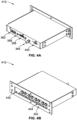
FIG. 1A illustrates a base and cassette style machine for ultrasonic welding according to an embodiment of the disclosure; -
FIG. 1B illustrates a cassette from the base and cassette style machine ofFIG. 1A ; -
FIG. 2 is a schematic of a base and cassette style machine showing component placements for ultrasonic welding in the prior art; -
FIG. 3 is a multipoint controller unit with Ethernet according to an embodiment of the disclosure; -
FIG. 4A is a perspective view of a multipoint controller unit according to an embodiment of the disclosure; -
FIG. 4B is another perspective view of the multipoint controller unit ofFIG. 4A ; -
FIG. 5 is a schematic of a base and cassette style machine with multipoint controller units according to an embodiment of the disclosure; -
FIG. 6 is a schematic of a base and cassette style machine with multipoint controller units connected in a daisy chain configuration, according to an embodiment of the disclosure; -
FIG. 7A is a schematic of a base and cassette style machine with two multipoint controller units paired to one power supply, according to an embodiment of the disclosure; -
FIG. 7B is a schematic of a base and cassette style machine with two multipoint controller units paired to one power supply, according to an embodiment of the disclosure; and -
FIG. 8 is a flow diagram illustrating a welding process using a multipoint controller unit according to an embodiment of the disclosure. - While the present disclosure is susceptible to various modifications and alternative forms, specific embodiments have been shown by way of example in the drawings and will be described in detail herein. It should be understood, however, that the present disclosure is not intended to be limited to the particular forms disclosed. Rather, the present disclosure is to cover all modifications, equivalents, and alternatives falling within the spirit and scope of the present disclosure as defined by the appended claims.
- Ultrasonic welders can commonly be used in "cassette" style machines, e.g., a base and
cassette style machine 100 depicted inFIG. 1A . The base andcassette style machine 100 includes abase 106 straddling acassette 104. Included on thebase 106 are power supplies 102-1, 102-2, 102-3, and 102-4.FIG. 1B shows thecassette 104 without thebase 106. Thecassette 104 is shown to hold multipleultrasonic welding probes 110 and several multipleprobe controller units 112. A single base can hold multiple cassettes, which allows for more cost-effective manufacturing of items (e.g., high-volume plastic parts) that have distinctly different details. This cost-effective manufacturing can be applied in automotive manufacturing, for example, in manufacturing automotive door panels, spoilers, instrumentation panels, and so on. - Cassette-style machines (e.g., the base and cassette style machine 100) allow for quick exchange of cassettes (e.g., the cassette 104). A cassette-style machine can have six to twelve ultrasonic generators (e.g., the power supplies 102) in its base. The cassette-style machine can also have a corresponding number of multiple probe controller units in the cassette. The cassette can also have about eighty ultrasonic probes. The cassettes can include analog distance sensors on the ultrasonic probes for controlling the weld. The analog distance sensors are sometimes connected to an analog input/output (I/O) card which is added to a programmable logic controller (PLC) located in the base of the cassette-style machine.
- Signals generated by the analog distance sensors can be sensitive to electronic noise. In conventional systems, wires connecting the analog I/O card of the PLC with the analog distance sensors must be carefully routed and shielded to protect from the electronic noise.
- The base and
cassette style machine 100 has the power supplies 102, the multipleprobe controller units 112, and the multiple ultrasonic welding probes 110 at different locations. The multipleprobe controller units 112 and the ultrasonic welding probes 110 are closer to one another than the power supplies 102 is to the multipleprobe controller units 112. Quick-change connectors on the base andcassette style machine 100 can be used to connect the power supplies 102 to the multipleprobe controller units 112. These quick-change connectors allow signal flow between components. Examples of signals that can flow through the connectors include high-voltage ultrasonic power signals from each power supply 102, discrete control signals, and analog signals from distance sensors. - The use of quick-change connectors introduces customization of mating connectors for both the
base 106 and thecassette 104. Machine builders are required to make multiple custom cables with proper wire terminations and shielding for high electrical noise environments. These customizations can significantly add to manufacturing and troubleshooting costs. Field support and maintenance of cassette-style machines with these customizations can be cumbersome and costly. - To illustrate distinctions between embodiments of the disclosure and prior art,
FIG. 2 provides a schematic of a base andcassette style machine 200 showing component placements forultrasonic power supplies 202, a PLC with analog I/O cards 201, and multipleprobe controller units 212 in the prior art. The PLC with analog I/O cards 201 and theultrasonic power supplies 202 are located in the base 206 while the multipleprobe controller units 212 and sets ofprobes 210 are located in thecassette 204. - The PLC with analog I/
O cards 201 has discrete connections to each of the ultrasonic power supplies 202-1, 202-2, ... 202-M via wires 222-1, 222-2, ... 222-M, respectively. The wires 222-1 to 222-M allow the PLC with analog I/O cards 201 to communicate with the ultrasonic power supplies 202-1 to 202-M, and vice versa. Each of theultrasonic power supplies 202 provides power to the sets ofprobes 210 via high-voltage ultrasound cables 214. Theultrasonic power supplies 202 also power the multipleprobe controller units 212 via customizedcables 216. Quick-change connectors 220 provide an interface between theultrasonic power supplies 202 and the multipleprobe controller units 212 for powering and communicating with the multipleprobe controller units 212. Quick-change connectors 218 provide an interface between theultrasonic power supplies 202 and the multipleprobe controller units 212 for providing an ultrasound signal to the probes sets ofprobes 210. Each probe within each set of probe 210-1, 210-2, ... 210-M includes actuators with analog distance sensors for communicating distance information to the PLC with analog I/O cards 201, via one ormore sensor cables 208 and aquick disconnect 219. - The PLC with analog I/
O cards 201 communicates with each of the ultrasonic power supplies 202-1, 202-2, ... 202-M to perform ultrasonic welding using distance and/or position of the sets ofprobes 210. The PLC with analog I/O cards 201 informs theultrasonic power supplies 202, via thewires 222, one selected probe within the set ofprobes 210 that should be active. A corresponding one of theultrasonic power supplies 202 responsible for the selected probe then updates the signals on a respective customizedcable 216 connected to a respective multipleprobe controller unit 212 so that the one selected probe is selected by the logic in the respective multipleprobe controller unit 212. - Distance and position can then be monitored using the analog distance sensor of the one selected probe to place the one selected probe within a preferred distance from the part to welded. The PLC with analog I/
O cards 201 monitors the distance based on the distance information received by the analog distance sensor. - The PLC with analog I/
O cards 201 then sends a signal to the corresponding one of theultrasonic power supplies 202 to turn on an ultrasound output for providing ultrasound power to the one selected probe. The PLC with analog I/O cards 201 can then monitor the analog distance sensor and send signal to the corresponding one of theultrasonic power supplies 202 to stop ultrasound output when a preferred reading is reached. Alternately, the weld may be controlled using Weld by Time or Weld by Energy modes, which do not require distance sensors or by the corresponding one of the power supplies 202 and the distance information is used by the PLC with analog I/O cards 201 to determine if a good weld occurred. - The PLC with analog I/
O cards 201 can then read weld cycle from the corresponding one of the ultrasonic power supplies if available. The process can be repeated with a different probe output selection. A drawback to using the PLC with analog I/O cards 201 is that the PLC with analog I/O cards 201 is responsible for multiple systems and not just the welding process, and as such, the distance information being monitored by the PLC with analog I/O cards 201 can be delayed and processed later. The delay which can be upwards of 20 milliseconds can result in a poorly welded part or a very slow welding process. - In some embodiments, the disclosure provides a base and cassette style machine with multipoint controller units having analog inputs that receive distance information from distance sensors. In some embodiments, the disclosure provides Ethernet style communication in place of discrete control signals.
-
FIG. 3 provides a block diagram of amultipoint controller unit 312 according to embodiments of the disclosure. Themultipoint controller unit 312 can include one or more high voltage relays 350 for controlling provision of high voltage ultrasound signal provided to ultrasonic probes connected to themultipoint controller unit 312. Themultipoint controller unit 312 includesSHV ports 352 for interfacing with the ultrasonic probes to provide the high voltage ultrasound signal to the ultrasonic probes. Themultipoint controller unit 312 includes a dedicated highvoltage input connector 364 for receiving ultrasound signal from an ultrasonic power supply. Themultipoint controller unit 312 includesmulti-channel distance inputs 356 for receiving analog distance information from the ultrasonic probes connected to themultipoint controller unit 312. - The
multipoint controller unit 312 can include abutton 360 for quickly pairing themultipoint controller unit 312 to an ultrasonic power supply. Themultipoint controller unit 312 can include amicrocontroller 354. Themicrocontroller 354 can control which of the high voltage relays 350 is active to provide ultrasonic power to a specific probe. Themicrocontroller 354 can interpret distance information received via themulti-channel distance inputs 356 to control a welding process. Themicrocontroller 354 can be programmed and controlled via aUSB port 358. Themicrocontroller 354 can communicate with an ultrasonic power supply via one ormore Ethernet ports 362. -
FIGS. 4A and 4B provide perspective views of amultipoint controller unit 412 according to an embodiment of the disclosure. Themultipoint controller unit 412 includes a housing with twoEthernet ports 362, theUSB port 358, the multi-channeldistance input port 356, a dedicated highvoltage input connector 364, apower input port 440, amain power LED 442,LED indicators 444, andSHV ports 352. - The
power input port 440 is a separate power port for powering electronics within themultipoint controller unit 412 such that power and communication ports of themultipoint controller unit 412 are decoupled in comparison to the multipleprobe controller units 212 ofFIG. 2 . The multipleprobe controller units 212 receive power and perform communication via the customizedcables 216. - The
main power LED 442 can be provided as a visual indicator of the status of themultipoint controller unit 412 on whether themultipoint controller unit 412 is receiving power via thepower input port 440. TheLED indicators 444 can be provided as visual indicators of which one of the multiple probes is being selected for receiving ultrasonic power. - In a base and cassette style machine (e.g., the base and cassette style machine 100), replacing the multiple probe controller unit with a multipoint controller unit (e.g., the multipoint controller unit 312) can provide architectural changes with several advantages.
FIG. 5 is a schematic of a base andcassette style machine 500 withmultipoint controller units 512 according to an embodiment of the disclosure. The base andcassette style machine 500 includes abase 506 and acassette 504. Thebase 506 includes aPLC 501, one or moreultrasonic power supplies 502, one ormore wires 522, one ormore Ethernet cables 516, and one or more highvoltage ultrasound cables 514. Thecassette 504 includes themultipoint controller units 512 and sets ofultrasonic probes 510. - The
PLC 501 is connected to the one or moreultrasonic power supplies 502 via the one ormore wires 522. The wires 522-1, 522-2, ... 522-M can be an industrial bus or discrete I/O connections for allowing communication between thePLC 501 and each of the power supplies 502-1, 502-2, ... 502-M. The Ethernet cables 516-1, 516-2, ... 516-M allow communication between each of the ultrasonic power supplies 502-1, 502-2, ... 502-M and the multipoint controller units 512-1, 512-2, ... 512-M. Thecassette 504 includes one or more ultrasonic power ports 518-1, 518-2, ... 518-M for receiving the wires 512-1, 512-2, ... 512-M. Thecassette 504 also includes one or more RJ-45 couplers 520-1, 520-2, ... 520-M for receiving the Ethernet cables 516-1, 516-2, ... 516-M. - Each set of probes 510-1, 510-2, ... 510-M includes at least one probe. Each set of probes 510-1, ... 510-M does not necessarily include a same number of probes. For example, the set of probes 510-1 can have eight probes while the set of probes 510-2 can have ten probes. Each probe within the set of
probes 510 includes distance sensors for providing distance information. The distance information is carried onsensor buses 508 from a respective set ofprobes 510 to a respectivemultipoint controller unit 512. For example, if the set of probes 510-1 contained six probes, then each of the six probes will generate distance information carried on sensor bus 508-1 to the multi-channel distance input port of the multipoint controller unit 512-1. - Comparing FIG. 5 to FIG. 2, some architectural differences are apparent. In
FIG. 5 , thePLC 501 is all digital, and themultipoint controller units 512 are able to process analog information. While inFIG. 2 , the PLC with analog I/O cards 201 is not all digital but includes custom analog I/O cards for processing analog information, and themultiple probe controller 212 is all digital. InFIG. 5 , themultipoint controller units 512 process the distance information provided by the sets ofprobes 510 while inFIG. 2 , the PLC with analog I/O cards 201 processes the distance information provided by the sets ofprobes 210. The sensor buses 508-1, 508-2, ... 508-M are much shorter than thesensor cables 208. As such, distance information can be provided to themultipoint controller units 512 much quicker than the PLC with analog I/O cards 501 due to slow I/O cards processing time. Furthermore, since the distance information are analog signals, longer cables being routed from the cassette to the base require electromagnetic shielding to protect signal integrity of the distance information. By having themultipoint controller units 512 process the distance information, wiring and electromagnetic requirements are alleviated. Also the embodiment ofFig. 2 requires additional quick disconnects (e.g., the quick disconnect 219) for analog distance sensors (e.g., the analog distance sensors 210) between the base 206 and each cassette (e.g., the cassette 204). - Due to the architectural changes, responsibilities of the PLC with analog I/
O cards 201 is different from responsibilities of thePLC 501 during a welding process. ThePLC 501 informs theultrasonic power supplies 502, via thewires 522, that one selected probe within the set ofprobes 510 should be active. A corresponding one of theultrasonic power supplies 502 responsible for the selected probe then updates the signals on arespective Ethernet cable 516 connected to a respectivemultipoint controller unit 512 so that the one selected probe is selected by the logic in the respectivemultipoint controller unit 512. - The
PLC 501 then sends a signal to the corresponding one of theultrasonic power supplies 502 to start the welding cycle and then waits for the welding cycle to finish. Once the welding cycle finishes, data from the corresponding one of theultrasonic power supplies 502 can be read by thePLC 501. The welding process can then continue with a different probe output selection. ThePLC 501 is not responsible for monitoring distance information, hence, the welding process can be controlled by the respectivemultipoint controller unit 512 monitoring the distance information without incurring delays from thePLC 501. - Embodiments of the disclosure provide several advantages. For example, Ethernet style communication removes the need for customized quick-change connectors (e.g., the quick-
change connectors 220 and thequick disconnect 219 inFIG. 2 ). Custom quick-change connectors can be replaced with inexpensive off the shelf RJ-45 couplers (e.g., the RJ-45couplers 520 inFIG. 5 ). Wiring costs can be significantly reduced by using off-the-shelf shielded CAT-5 cables and avoiding customized cables. Using the CAT-5 cables and the RJ-45 couplers can also reduce risk of mis-wiring signals. Using these cables and couplers can also reduce risk of improper cable shielding from a customized cable. Since Ethernet communication uses differential signals passed over twisted pairs of wires, electronic noise generated by high voltage signals that might be nearby has much less effect on communication between power supplies (e.g., theultrasonic power supplies 502 inFIG. 5 ) and multipoint controller units (e.g., themultipoint controller units 512 inFIG. 5 ), according to some embodiments of the disclosure. - Ethernet hardware can be used with a communication protocol transparent to other protocols such as TCP/IP and industrial automation protocols. Multipoint controller units with Ethernet can run concurrently on the same physical network with a PLC, ultrasonic power supplies, and other devices. The protocol data can be transmitted using custom Ethernet frames that avoid collision with existing network protocols residing on a same physical network. The communication protocol can also provide for error checking which is unavailable with discrete wiring provided in
FIG. 2 . - Ethernet style communication allows for more feedback information about a state of an multipoint controller unit (e.g., the multipoint controller unit 512-1 of
FIG. 5 ) to be passed to an ultrasonic power supply (e.g., the ultrasonic power supply 502-1) and vice versa, without a need for an unwieldy and expensive cable (e.g., the customizedcable 216 ofFIG. 2 ) that would be required for discrete connections. Ethernet style communication can support port forwarding which can allow multiple multipoint controller units to be daisy chained without the use of an external switch. That way, in a network with multiple multipoint controller units and power supplies, one switch port can be used to communicate with all multiple controller units. -
FIG. 6 is a schematic of a base andcassette style machine 600 with multipoint controller units 612 connected in a daisy chain configuration, according to an embodiment of the disclosure. The base andcassette style machine 600 includes abase 606 and acassette 604 with the base 606 including aPLC 601, one or moreultrasonic power supplies 602, and anEthernet switch 630. Thecassette 604 includes multipoint controller units 612 and sets ofprobes 610. The sets ofprobes 610 include distance sensors for providing distance information to the multipoint controller units 612 via the sensor busses 608. The high voltage ultrasound cables from theultrasonic power supplies 602 for providing ultrasonic power to the sets ofprobes 610 are not shown inFIG. 6 . - The PLC 601 (similar to or the same as the PLC 501) is connected to the
Ethernet switch 630. The ultrasonic power supplies 602-1, 602-2, ... 602-M are also connected to theEthernet switch 630. An RJ-45coupler 620 of thecassette 604 is also connected to theEthernet switch 630. TheEthernet switch 630 facilitates communication between thePLC 601 and each of the ultrasonic power supplies 602-1, 602-2, 602-3, ... 602-M.The Ethernet switch 630 also facilitates communication between the ultrasonic power supplies 602-1, 602-2, 602-3, ... 602-M and the multipoint controller units 612-1, 612-2, 612-3, ... 612-N. - The multipoint controller units 612-1, 612-2, 612-3, ... 612-N are arranged in a daisy chain configuration. In an embodiment, each multipoint controller unit 612-2, 612-3, ... 612-N includes at least two Ethernet ports to facilitate connecting the multipoint controller units in a daisy chain configuration. One or
more Ethernet cables 632 are used in connecting the multipoint controller units 612 in the daisy chain configuration. The daisy chain configuration allows the multipoint controller units 612 to share the RJ-45coupler 620 of thecassette 604. As shown inFIG. 6 , using an Ethernet switch (e.g., the Ethernet switch 630) in the machine base will allow multiple power supplies to control multiple multipoint controller units 612 with a single connection between the base and the cassette. - According to the invention, multiple ultrasonic power supplies and multiple multipoint controller units can exist on the same network without interfering with one another. Specific multipoint controller units can be paired with specific power supplies. A power supply can be paired with multiple multipoint controller units which will switch the ultrasound signal in a daisy-chained fashioned, expanding the total probe selections available to the power supply.
FIG. 7A is a schematic of a base andcassette style machine 700 with two multipoint controller units 712-3 and 712-4 paired to one power supply 702-3, according to an embodiment of the disclosure. - The base and
cassette style machine 700 includes aPLC 701 and three power supplies 702-1, 702-2, and 702-3. ThePLC 701 and the three power supplies 702 are connected to anEthernet switch 730. TheEthernet switch 730, similar toEthernet switch 630, facilitates communication between the three power supplies 702 and thePLC 701. TheEthernet switch 730 also facilitates communication between each of the three power supplies 702 and each of the multipoint controller units 712-1, 712-2, 712-3, and 712-4, via the RJ-45coupler 720. Each respective multipoint controller unit 712 controls ultrasonic power provided to a set of probes 710. The set of probes 710 provide distance information to the multipoint controller units 712 via the sensor busses 708. Similar toFIG. 6 , the multipoint controller units 712 are daisy chained usingEthernet cables 732. - To provide ultrasonic power to the set of probes 710, the power supplies 702 have high voltage connections to the multiport controller units 712 via wires 714. The power supply 702-1 is connected to the multipoint controller unit 712-1 via the wire 714-1 and a power port 718-1. The power supply 702-2 is connected to the multipoint controller unit 712-2 via the wire 714-2 and a power port 718-2. The power supply 702-3 is connected to the multipoint controller unit 712-3 via the wire 714-3 and a power port 718-3. The power supply 702-3 is also connected to the multipoint controller unit 712-4 via a daisy chained power configuration between the multipoint controller unit 712-3 and the multipoint controller unit 712-4. The daisy chained power configuration allows ultrasonic power to flow from the power supply 702-3 to the multipoint controller unit 712-3, then from the multipoint controller unit 712-3 via a
wire 734 to the multipoint controller unit 712-4. - In
FIG. 7A , the power supply 702-3 provides ultrasonic power to the set of probes 710-3 and 710-4. The power supply 702-3 can also communicate with both the multipoint controller units 712-3 and 712-4 via the RJ-45coupler 720. As such, the power supply 702-3 can be paired to more than one multipoint controller unit 712. Although a one-to-two pairing is shown as an example inFIG. 7A , a power supply can be paired with more than two multipoint controller units. - Similar to
FIG. 7A ,FIG. 7B is a schematic of the base andcassette style machine 700 with two multipoint controller units 712-3 and 712-4 paired to one power supply 702-3, according to an embodiment of the disclosure. Instead of using a daisy chain configuration as inFIG. 7A ,FIG. 7B splits the ultrasonic power from the power supply 702-3 using ahigh voltage tee 736. Thehigh voltage tee 736 acts as a power splitter that allows the power supply 702-3 to provide power to the set of probes 708-3 via the multipoint controller unit 712-3 and also provide power to the set of probes 708-4 via the multipoint controller unit 712-4. - Embodiments of the disclosure provide several advantages. Multi-channel analog inputs located in the multipoint controller units (e.g., the multipoint controller units 712 of
FIG. 7A ) allow welding using distance or position sensors without costly analog I/O cards for the PLC. In a base and cassette style machine, multipoint controller units can usually be located close to the ultrasonic probes, so having the analog distance inputs in the multipoint controller units can significantly reduce machine wiring costs and risk of induced electrical noise. - Having the analog distance inputs in the multipoint controller units reduces the distance that the distance information from the analog distance sensors travels. As such, welding using the distance information can be much more accurate due to the multipoint controller units having a much faster sampling rate than most PLCs. The rate at which a PLC can sample distance information from the analog distance sensors can be dependent on scan time, which is determined by processor speed, number of program steps, number of I/Os, and so on. The accuracy of a trigger position for starting the welding process and accuracy of a weld end position or distance is directly affected by the scan time. Scan time for modern PLCs is often from several milliseconds up to 20 ms.
- Communication protocol using Ethernet cable can be custom designed for the multipoint controller units to exhibit custom frame types with messages specific to the multipoint controller units. The communication protocol enables for remote pairing of a power supply to a multipoint controller unit to form a master-slave control relationship that is protected from outside influence using shared secrets established during the pairing operation. The pairing operation forms a logical control channel between a respective power supply and a respective multipoint controller unit, emulating discrete physical I/O. The physical network topology between a paired multipoint controller unit and a power supply can change without affecting the logical connection. That is, for example, consider that the ultrasonic power supplies 602-2 and 602-3 were logically paired to the multipoint controller units 612-2 and 612-3, respectively, and positions of the multipoint controller units 612-2 and 612-3 were swapped in the daisy chain connection. Even through there has been a change to the physical configuration of the multipoint controller units 612-2 and 612-3, the multipoint controller units 612-2 and 612-3 would keep their paired logical connection to the power supplies 602-2 and 602-3, respectively.
- The communication protocol can support both a simple tool free "one button" paring operation and a more comprehensive operation using a personal computer (PC) utility. The "one button" paring operation can be used for quick field replacement of a known bad unit. The PC utility supported operation can provide detailed pairing status and system identification information (such as model number, serial number, firmware versions) useful for debugging tasks. Both the "one button" pairing option and the PC utility option are simpler than any PLC development tool, thus enabling maintenance personnel with lower levels of training than what might be required by a PLC based network.
- In an embodiment, each multipoint controller unit (e.g., the multipoint controller units 612) can be in one of three states with respect to the communication protocol. The three states include an unpaired state ("UNPAIRED" state), a paired but unconnected state ("UNCONNECTED" state), and a paired and connected state ("CONNECTED" state). The real time control and status information is exchanged only in the CONNECTED state. Each paired multipoint controller unit should be in the CONNECTED state to be operational.
- In an embodiment, a paired multipoint controller unit (e.g., the multipoint controller units 612) can detect incorrect wiring of the high voltage ultrasound cables between the power supply and the multipoint controller unit. For example, when the multipoint controller unit 612-2 is paired to the ultrasonic power supply 602-1, the multipoint controller unit 612-2 is in communication with the ultrasonic power supply 602-1. During a welding process, if the ultrasonic power supply 602-1 indicates that it is providing ultrasonic power to the multipoint controller unit 612-2 but the multipoint controller unit 612-2 does not receive any ultrasonic power at its ultrasonic power input (e.g., the ultrasonic power input 364), the multipoint controller unit 612-2 can provide a signal for stopping power delivery from the ultrasonic power supply 602-1. The multipoint controller unit 612-2 can determine that ultrasonic power output from the power supply 602-1 is not correctly wired to the multipoint controller unit 612-2.
- Multipoint controller units according to embodiments of the disclosure being used in base and cassette style machines can allow welding to start and stop using distance information. In some embodiments, the distance information can be used to determine a quality of the weld.
FIG. 8 is a flow diagram illustrating a welding process using a multipoint controller unit (e.g., the multipoint controller unit 612-1) according to an embodiment of the disclosure. Atstep 802, the multipoint controller unit is paired to a power supply. For example, the multipoint controller unit 612-1 is paired to the power supply 602-1 using either a "one button" pairing or a PC utility pairing according to embodiments of the disclosure. - At
step 804, the multipoint controller unit 612-1 monitors distance information received from a selected probe in the set of probes 610-1. Atstep 806, the multipoint controller unit 612-1 determines via the distance information whether a trigger position has been reached. The trigger position is a distance separating the selected probe from a particular location on the part being welded. The probe or the part is continuously being moved until the trigger position is reached. If the trigger position is not met, the distance information is monitored atstep 804. Trigger by power method also could be used to start ultrasonic welding. - If the trigger position is met, then at
step 808, the multipoint controller unit 612-1 sends a signal to the power supply 602-1 to deliver ultrasonic power to the multipoint controller unit 612-1 for the selected probe. The signal is sent through Ethernet via theEthernet switch 630. - As power is delivered, the distance information from the selected probe in the set of probes 610-1 is monitored. As the part is being welded, a target collapse distance is checked for at
step 812. If the target collapse distance is not reached, then the distance information is continuously monitored atstep 810. - If the target collapse distance is reached, then at
step 814, the multipoint controller unit 612-1 sends a signal to the power supply 602-1 to stop delivering ultrasonic power to the multipoint controller unit 612-1. The signal is sent through Ethernet, via theEthernet switch 630. - At
step 816, the multipoint controller unit 612-1 can send data on the welding process to the power supply. The data can include a quality status of the completed weld. - While the present disclosure has been described with reference to one or more particular embodiments and implementations, those skilled in the art will recognize that many changes may be made as long as they are not departing from the scope of the present invention, which is set forth in the claims that follow.
Claims (11)
- A system for providing power to more than one ultrasonic welding probe (110, 210, 510, 610, 710) from M power supplies (102, 202, 502, 602, 702) the system comprising:N multipoint units (112, 212, 312, 412, 512, 612, 712), each of the N multipoint units including:a housing,a plurality of analog or digital inputs configured to carry distance information regarding probe distance of a plurality of ultrasonic welding probes (110, 210, 510, 610, 710),a dedicated high voltage input connector (364) connectable via a high voltage cable (214, 514, 714) to a dedicated high voltage output connector of one of the M power supplies (102, 202, 502, 602, 702),at least one Ethernet port (362), anda microcontroller (354), configured todirect power from the dedicated high voltage input connector to a corresponding one of the plurality of ultrasonic welding probes (110, 210, 510, 610, 710), andsample the distance information of the plurality of ultrasonic welding probes (110, 210, 510, 610, 710) at a rate of at least once per millisecond; anda base housing the M power supplies (102, 202, 502, 602, 702), wherein M and N are both integers greater than or equal to 1,each of the N multipoint units being interconnected by Ethernet to form a network having as components the N multipoint units (112, 212, 312, 412, 512, 612, 712) and the M power supplies (102, 202, 502, 602, 702) such that (i) each of the N multipoint units (112, 212, 312, 412, 512, 612, 712) is paired with a different one of the M power supplies (102, 202, 502, 602, 702) in the network, avoiding interference between any of the N multipoint units (112, 212, 312, 412, 512, 612, 712) and any of the M power supplies (102, 202, 502, 602, 702) and (ii) a first one of the N multipoint units (112, 212, 312, 412, 512, 612, 712) is paired with a first one of the M power supplies (102, 202, 502, 602, 702) in the network, the microcontroller (354) of the first one of the N multipoint units (112, 212, 312, 412, 512, 612, 712) being configured to:receive a signal from the first one of the M power supplies (102, 202, 502, 602, 702) via the network, the signal indicating that the first one of the M power supplies (102, 202, 502, 602, 702) is providing power to the dedicated high voltage input connector of the first one of the N multipoint units (112, 212, 312, 412, 512, 612, 712),detect a power level at the dedicated high voltage input connector of the first one of the N multipoint units (112, 212, 312, 412, 512, 612, 712), andresponsive to the detected power level being below a threshold, generate an error signal for the first one of the M power supplies (102, 202, 502, 602, 702) to stop providing power.
- The system of claim 1, wherein a first multipoint unit of the N multipoint units (112, 212, 312, 412, 512, 612, 712) further includes a button configured to form a pairing between the first multipoint unit and a first one of the M power supplies (102, 202, 502, 602, 702).
- The system of claim 1, wherein a first multipoint unit of the N multipoint units (112, 212, 312, 412, 512, 612, 712) further includes a universal serial bus (USB) port, the USB port configured to receive signals from a computing device for forming a pairing between the first multipoint unit and a first one of the M power supplies (102, 202, 502, 602, 702).
- The system of claim 1, wherein the pairing between the first one of the M power supplies (102, 202, 502, 602, 702) and the first one of the TV multipoint units (112, 212, 312, 412, 512, 612, 712) forms a logical control channel between both such that a physical change in a physical topology of the network does not disrupt the logical control channel between the first one of the M power supplies (102, 202, 502, 602, 702) and the first one of the N multipoint units (112, 212, 312, 412, 512, 612, 712).
- The system of claim 2, wherein the N multipoint units (112, 212, 312, 412, 512, 612, 712) and the M power supplies (102, 202, 502, 602, 702) are configured to communicate according to a custom communication protocol that supports a pairing operation and allows control status and information to be exchanged.
- The system of claim 5, wherein for a first multipoint unit in the N multipoint units (112, 212, 312, 412, 512, 612, 712), the at least three states include a first state indicating that the first multipoint unit is not paired with any of the M power supplies (102, 202, 502, 602, 702), a second state indicating that the first multipoint unit is paired to a first power supply in the M power supplies (102, 202, 502, 602, 702) but is not connected to the first power supply, and a third state indicating that the first multipoint unit is paired with the first power supply and is connected to the first power supply.
- The system of claim 1, further comprising:
an Ethernet switch (630, 730) configured to physically interface the N multipoint units (112, 212, 312, 412, 512, 612, 712) with a programmable logic controller (PLC). - The system of claim 7, wherein:the at least one Ethernet port (362) of each of the N multipoint units (112, 212, 312, 412, 512, 612, 712) is at least two Ethernet ports (362); andthe Ethernet switch (630, 730) is further configured to receive N Ethernet cables (516, 732) from the N multipoint units (112, 212, 312, 412, 512, 612, 712).
- The system of claim 7, wherein:the at least one Ethernet port (362) of each of the N multipoint units (112, 212, 312, 412, 512, 612, 712) is at least two Ethernet ports (362); andthe Ethernet switch (630, 730) is further configured to interface the M power supplies (102, 202, 502, 602, 702) with the N multipoint units, the N multipoint units (112, 212, 312, 412, 512, 612, 712) being arranged in the network in a daisy chained manner such that the Ethernet switch (630, 730) receives a single Ethernet cable (516, 732) from one of the N multipoint units (112, 212, 312, 412, 512, 612, 712).
- The system of claim 1, wherein the microcontroller (354) of a first multipoint unit in the N multipoint units (112, 212, 312, 412, 512, 612, 712) is further configured to:compare distance information of a corresponding one of the plurality of ultrasonic welding probes (110, 210, 510, 610, 710) to determine whether the distance information indicates that a threshold has been violated; andgenerating an error signal to stop a welding process based on the threshold being violated.
- The system of claim 10, wherein the error signal is generated after the welding process has begun.
Applications Claiming Priority (3)
| Application Number | Priority Date | Filing Date | Title |
|---|---|---|---|
| US16/541,954 US10710310B1 (en) | 2019-08-15 | 2019-08-15 | Multipoint controllers for power delivery to multiple probes in ultrasonic welding systems |
| US16/898,030 US20210046712A1 (en) | 2019-08-15 | 2020-06-10 | Multipoint controllers for power delivery to multiple probes in ultrasonic welding systems |
| PCT/US2020/046517 WO2021030753A1 (en) | 2019-08-15 | 2020-08-14 | Multipoint controllers for power delivery to multiple probes in ultrasonic welding systems |
Publications (2)
| Publication Number | Publication Date |
|---|---|
| EP4013551A1 EP4013551A1 (en) | 2022-06-22 |
| EP4013551B1 true EP4013551B1 (en) | 2024-10-23 |
Family
ID=71519917
Family Applications (1)
| Application Number | Title | Priority Date | Filing Date |
|---|---|---|---|
| EP20768734.4A Active EP4013551B1 (en) | 2019-08-15 | 2020-08-14 | Multipoint controllers for power delivery to multiple probes in ultrasonic welding systems |
Country Status (7)
| Country | Link |
|---|---|
| US (2) | US10710310B1 (en) |
| EP (1) | EP4013551B1 (en) |
| JP (1) | JP7663552B2 (en) |
| CN (1) | CN114302803B (en) |
| ES (1) | ES2998387T3 (en) |
| PL (1) | PL4013551T3 (en) |
| WO (1) | WO2021030753A1 (en) |
Families Citing this family (1)
| Publication number | Priority date | Publication date | Assignee | Title |
|---|---|---|---|---|
| CN117564434B (en) * | 2024-01-15 | 2024-04-30 | 钛玛科(北京)工业科技有限公司 | Ultrasonic double-roll welding device and method |
Citations (7)
| Publication number | Priority date | Publication date | Assignee | Title |
|---|---|---|---|---|
| US4549684A (en) * | 1983-02-25 | 1985-10-29 | Telly Gary R | Ultrasonic welding system and method employing a reduced number of power supplies |
| US20050061848A1 (en) * | 2003-09-22 | 2005-03-24 | Johansen David K. | Multiple probe power systems and methods for ultrasonic welding |
| CN101707380A (en) * | 2008-07-21 | 2010-05-12 | 北京星网锐捷网络技术有限公司 | Method, device and system for configuring power supply system |
| US20140117921A1 (en) * | 2012-10-26 | 2014-05-01 | Nokia Corporation | Method, apparatus, and computer program product for optimized device-to-device charging |
| US20150263548A1 (en) * | 2014-03-14 | 2015-09-17 | Emily Cooper | Systems and methods for wireless power distribution allocation |
| US20160041597A1 (en) * | 2014-08-06 | 2016-02-11 | Apple Inc. | Reduced-size user interfaces for battery management |
| WO2016077140A1 (en) * | 2014-11-14 | 2016-05-19 | Motorola Solutions, Inc. | Method and apparatus for efficiency compliance in wireless charging systems |
Family Cites Families (61)
| Publication number | Priority date | Publication date | Assignee | Title |
|---|---|---|---|---|
| US3029766A (en) | 1956-05-02 | 1962-04-17 | Aeroprojects Inc | Ultrasonic tool |
| US2995689A (en) | 1958-10-13 | 1961-08-08 | Gulton Ind Inc | Ultrasonic control circuit |
| US3559257A (en) | 1968-03-12 | 1971-02-02 | Jerome H Lemelson | Machine control apparatus |
| US3780926A (en) | 1972-06-02 | 1973-12-25 | Dukane Corp | Ultrasonic rigid horn assembly |
| JPS5123342B2 (en) | 1972-07-31 | 1976-07-16 | ||
| US3825481A (en) | 1973-04-30 | 1974-07-23 | Kane Corp Du | Fluid flow sonic energy reactor |
| US4064462A (en) | 1976-12-29 | 1977-12-20 | Dukane Corporation | Acoustic feedback peak elimination unit |
| US4131505A (en) | 1977-12-12 | 1978-12-26 | Dukane Corporation | Ultra-sonic horn |
| JPS5828049Y2 (en) | 1978-05-04 | 1983-06-18 | 株式会社クボタ | Stand device for work equipment with lift arm |
| US4208001A (en) | 1979-01-05 | 1980-06-17 | Dukane Corporation | Ultrasonic metal welding apparatus |
| US4277710A (en) | 1979-04-30 | 1981-07-07 | Dukane Corporation | Control circuit for piezoelectric ultrasonic generators |
| US4401501A (en) | 1981-03-11 | 1983-08-30 | Simmons Usa Corporation | Apparatus for making assemblies of pocketed springs |
| US4746051A (en) | 1982-12-08 | 1988-05-24 | General Motors Corporation | Ultrasonic welding control |
| US4696425A (en) | 1984-07-17 | 1987-09-29 | Texas Instruments Incorporated | Programmable ultrasonic power supply |
| US4631685A (en) * | 1984-12-07 | 1986-12-23 | General Motors Corporation | Method and apparatus for ultrasonic plastic forming and joining |
| JPH0763673B2 (en) * | 1987-08-13 | 1995-07-12 | 株式会社彦間製作所 | Vibration device |
| US4838639A (en) | 1987-11-02 | 1989-06-13 | Dukane Corporation | Method and apparatus for orienting a fiber optic member |
| US4914290A (en) | 1988-04-06 | 1990-04-03 | Dukane Corporation | Method and apparatus for measuring of microdistances |
| EP0389704B1 (en) | 1989-03-31 | 1994-07-20 | Kabushiki Kaisha Toshiba | Welder apparatus |
| DE4030989A1 (en) * | 1990-10-01 | 1992-04-09 | Airbus Gmbh | Fibre reinforced laminated thermoplastic component - has pis inserted across layers to increase peel strength |
| US5295700A (en) | 1992-04-16 | 1994-03-22 | Dukane Corporation | Workpiece support assembly for microrobotic apparatus |
| US5798599A (en) | 1996-10-24 | 1998-08-25 | Dukane Corporation | Ultrasonic transducer assembly using crush foils |
| US5880580A (en) | 1998-01-29 | 1999-03-09 | Dukane Corporation | Automatic regulation of power delivered by ultrasonic transducer |
| WO2000000344A1 (en) * | 1998-06-30 | 2000-01-06 | Trustees Of Tufts College | Multiple-material prototyping by ultrasonic adhesion |
| US6251203B1 (en) | 1999-06-23 | 2001-06-26 | General Mills, Inc. | Apparatus and method for assembling a plastic container for food products |
| US6441352B1 (en) * | 2000-01-05 | 2002-08-27 | Ef Technologies, Inc. | Apparatus for electrically heat welding thermoplastic fittings and method of using the same |
| US6472634B1 (en) * | 2001-04-17 | 2002-10-29 | Lincoln Global, Inc. | Electric arc welding system |
| US6847008B2 (en) * | 2003-01-17 | 2005-01-25 | Lincoln Global, Inc. | Electric arc welding system |
| US6984921B1 (en) | 2003-02-21 | 2006-01-10 | Dukane Corporation | Apparatus and method for resonant mounting of vibration structure |
| US7105772B2 (en) * | 2003-03-24 | 2006-09-12 | Lincoln Global, Inc. | Arc welding system and method |
| US20060213952A1 (en) * | 2003-09-22 | 2006-09-28 | Dukane Corporation | Multiple probe power systems and methods for ultrasonic welding |
| US20060011707A1 (en) | 2003-09-22 | 2006-01-19 | Dukane Corporation | Multiple probe power systems and methods for ultrasonic welding |
| US7091446B2 (en) * | 2003-12-15 | 2006-08-15 | Lincoln Global, Inc. | Electric arc welding system |
| US7105773B2 (en) * | 2004-01-12 | 2006-09-12 | Lincoln Global, Inc. | Electric arc welder |
| US8895896B2 (en) * | 2004-01-12 | 2014-11-25 | Lincoln Global, Inc. | Modified series arc welding and improved control of one sided series arc welding |
| US7053334B2 (en) * | 2004-03-01 | 2006-05-30 | Lincoln Global, Inc. | Electric arc welder system with waveform profile control |
| US7166817B2 (en) * | 2004-04-29 | 2007-01-23 | Lincoln Global, Inc. | Electric ARC welder system with waveform profile control for cored electrodes |
| ES2353520T3 (en) * | 2005-08-01 | 2011-03-02 | Agie Charmilles Sa | PROCEDURE OF OPERATION OF A MACHINING MACHINE BY ELECTROEROSION AND A SYSTEM OF MACHINING BY ELECTROEROSION. |
| RU2006147217A (en) * | 2005-12-29 | 2008-07-10 | Дюкейн Корпорейшн (Us) | SYSTEMS FOR ACCESSING THE REGULATED POWER TO THE HEADS FOR ULTRASONIC WELDING |
| US9914263B2 (en) * | 2006-05-08 | 2018-03-13 | Dukane Ias, Llc | Ultrasonic press with automatic speed changes in advancing movement of welding stack |
| KR100789012B1 (en) * | 2006-05-08 | 2007-12-26 | 대우조선해양 주식회사 | Small member welding robot self-diagnosis system |
| US8052816B2 (en) * | 2006-05-08 | 2011-11-08 | Dukane Corporation | Ultrasonic press using servo motor with delayed motion |
| WO2008018935A2 (en) | 2006-05-08 | 2008-02-14 | Dukane Corporation | Ultrasonic press using servo motor with integrated linear actuator |
| DE102006043605B3 (en) * | 2006-09-16 | 2008-03-27 | Stapla Ultraschalltechnik Gmbh | Method for quality monitoring in ultrasonic welding |
| WO2009146176A1 (en) * | 2008-04-14 | 2009-12-03 | Blake Larson | Device and method for mri-guided breast interventions |
| US20100286527A1 (en) * | 2009-05-08 | 2010-11-11 | Penrith Corporation | Ultrasound system with multi-head wireless probe |
| TWI440277B (en) * | 2011-05-20 | 2014-06-01 | Powertech Ind Co Ltd | Power controller, power controlling device and power saving method for power controlling device |
| US9839967B2 (en) * | 2011-11-08 | 2017-12-12 | Lincoln Global, Inc. | System and method for real-time computation and reporting of welding machine performance and metrics |
| US8967216B2 (en) * | 2011-12-01 | 2015-03-03 | Apci, Llc | Linear friction welder with helical groove |
| CN203004324U (en) * | 2013-01-10 | 2013-06-19 | 盘吉军 | Ultrasonic plastic welder |
| US9688017B2 (en) * | 2013-05-14 | 2017-06-27 | Dukan IAS, LLC | Vibration welders with high frequency vibration, position motion control, and delayed weld motion |
| US9658612B2 (en) * | 2013-12-13 | 2017-05-23 | GM Global Technology Operations LLC | Automatic monitoring of the alignment and wear of vibration welding equipment |
| US10105787B2 (en) * | 2015-06-05 | 2018-10-23 | GM Global Technology Operations LLC | Systems and methods for ultrasonic welding |
| US10406624B2 (en) * | 2016-03-07 | 2019-09-10 | Illinois Tool Works Inc. | Methods and apparatus to switch a weld power output |
| WO2017213981A1 (en) * | 2016-06-02 | 2017-12-14 | Miller Weldmaster Corporation | Method and apparatus for tracking weld data |
| US10773331B2 (en) * | 2016-08-16 | 2020-09-15 | Illinois Tool Works Inc. | Welding power supplies, wire feeders, and systems to compensate a weld voltage via communications over a weld circuit |
| CN108111316B (en) * | 2016-11-25 | 2020-02-11 | 新华三技术有限公司 | PSE (Power supply Environment) |
| CN107053680A (en) * | 2016-12-07 | 2017-08-18 | 必能信超声(上海)有限公司 | Ultrasonic welding machine and control method |
| CN111386170A (en) * | 2017-11-29 | 2020-07-07 | 远程声波控股公司 | Ultrasonic machining apparatus, method of configuring ultrasonic machining apparatus, and system having ultrasonic machining apparatus |
| US10534024B2 (en) * | 2017-12-22 | 2020-01-14 | Schneider Electric USA, Inc. | Single pole low-cost expandable smart panel monitoring and control system |
| CN209051047U (en) * | 2018-11-17 | 2019-07-02 | 芜湖新宝超声波设备有限公司 | The synchronous ultrasonic welding post of arc car inner plate decoration |
-
2019
- 2019-08-15 US US16/541,954 patent/US10710310B1/en active Active
-
2020
- 2020-06-10 US US16/898,030 patent/US20210046712A1/en not_active Abandoned
- 2020-08-14 JP JP2022507611A patent/JP7663552B2/en active Active
- 2020-08-14 WO PCT/US2020/046517 patent/WO2021030753A1/en not_active Ceased
- 2020-08-14 ES ES20768734T patent/ES2998387T3/en active Active
- 2020-08-14 PL PL20768734.4T patent/PL4013551T3/en unknown
- 2020-08-14 EP EP20768734.4A patent/EP4013551B1/en active Active
- 2020-08-14 CN CN202080057767.1A patent/CN114302803B/en active Active
Patent Citations (7)
| Publication number | Priority date | Publication date | Assignee | Title |
|---|---|---|---|---|
| US4549684A (en) * | 1983-02-25 | 1985-10-29 | Telly Gary R | Ultrasonic welding system and method employing a reduced number of power supplies |
| US20050061848A1 (en) * | 2003-09-22 | 2005-03-24 | Johansen David K. | Multiple probe power systems and methods for ultrasonic welding |
| CN101707380A (en) * | 2008-07-21 | 2010-05-12 | 北京星网锐捷网络技术有限公司 | Method, device and system for configuring power supply system |
| US20140117921A1 (en) * | 2012-10-26 | 2014-05-01 | Nokia Corporation | Method, apparatus, and computer program product for optimized device-to-device charging |
| US20150263548A1 (en) * | 2014-03-14 | 2015-09-17 | Emily Cooper | Systems and methods for wireless power distribution allocation |
| US20160041597A1 (en) * | 2014-08-06 | 2016-02-11 | Apple Inc. | Reduced-size user interfaces for battery management |
| WO2016077140A1 (en) * | 2014-11-14 | 2016-05-19 | Motorola Solutions, Inc. | Method and apparatus for efficiency compliance in wireless charging systems |
Also Published As
| Publication number | Publication date |
|---|---|
| US10710310B1 (en) | 2020-07-14 |
| CN114302803A (en) | 2022-04-08 |
| PL4013551T3 (en) | 2025-03-10 |
| ES2998387T3 (en) | 2025-02-20 |
| CN114302803B (en) | 2024-06-14 |
| JP2022545622A (en) | 2022-10-28 |
| WO2021030753A1 (en) | 2021-02-18 |
| JP7663552B2 (en) | 2025-04-16 |
| US20210046712A1 (en) | 2021-02-18 |
| EP4013551A1 (en) | 2022-06-22 |
Similar Documents
| Publication | Publication Date | Title |
|---|---|---|
| EP3421932B1 (en) | Self-configuring component identification and signal processing system for a coordinate measurement machine | |
| EP1277096B1 (en) | Driver board control system for modular conveyor with address-based network for inter-conveyor communication | |
| EP4013551B1 (en) | Multipoint controllers for power delivery to multiple probes in ultrasonic welding systems | |
| US5392424A (en) | Apparatus for detecting parity errors among asynchronous digital signals | |
| EP2829932A2 (en) | Robot system, production management computer, and method of controlling a production management computer | |
| CN111163308A (en) | Rotary camera module inspection device that distributes inspection data processing load | |
| US6876942B2 (en) | Methods and systems for enhanced automated system testing | |
| JP2021092861A (en) | Electronic device | |
| US10867504B2 (en) | Monitoring of marshalling cabinet wiring | |
| US9470736B2 (en) | Wiring test device for electronics cabinets having internal signal wiring | |
| US20240103498A1 (en) | Systems and methods of remotely controlling channel resets for input/output modules of industrial systems | |
| US12230230B2 (en) | Systems and methods of fault detection for input/output modules of industrial systems | |
| KR102469505B1 (en) | Connection inspecting apparatus | |
| CN107632566A (en) | A kind of board identification device, method and the network equipment | |
| EP3075219B1 (en) | Automated module for assembly lines and method to actuate and control thereof | |
| EP2693568A1 (en) | Module connector for uninterrupted communication | |
| JP3927482B2 (en) | Simulation device | |
| JP2007133579A (en) | Industrial device virtual simulation system and device controller | |
| Yamashita et al. | Distributed Remote Input/Output Control Method in Real Time Processing for CNC | |
| JP2001144492A (en) | Micro device processing system | |
| US11764088B2 (en) | Method for testing a standard interface and interface-tester | |
| EP3593604A1 (en) | System and method for flexible connection of redundant input/output modules or other devices | |
| WO2014071982A1 (en) | A robot controller arrangement, a robot system and a method therefor | |
| JP3708811B2 (en) | Computer integrated production system and parallel monitoring device for serial communication applied thereto | |
| CN118884164A (en) | Method and device for automated testing, testing system, and computer-readable storage medium |
Legal Events
| Date | Code | Title | Description |
|---|---|---|---|
| STAA | Information on the status of an ep patent application or granted ep patent |
Free format text: STATUS: UNKNOWN |
|
| STAA | Information on the status of an ep patent application or granted ep patent |
Free format text: STATUS: THE INTERNATIONAL PUBLICATION HAS BEEN MADE |
|
| PUAI | Public reference made under article 153(3) epc to a published international application that has entered the european phase |
Free format text: ORIGINAL CODE: 0009012 |
|
| STAA | Information on the status of an ep patent application or granted ep patent |
Free format text: STATUS: REQUEST FOR EXAMINATION WAS MADE |
|
| 17P | Request for examination filed |
Effective date: 20220207 |
|
| AK | Designated contracting states |
Kind code of ref document: A1 Designated state(s): AL AT BE BG CH CY CZ DE DK EE ES FI FR GB GR HR HU IE IS IT LI LT LU LV MC MK MT NL NO PL PT RO RS SE SI SK SM TR |
|
| DAV | Request for validation of the european patent (deleted) | ||
| DAX | Request for extension of the european patent (deleted) | ||
| GRAP | Despatch of communication of intention to grant a patent |
Free format text: ORIGINAL CODE: EPIDOSNIGR1 |
|
| STAA | Information on the status of an ep patent application or granted ep patent |
Free format text: STATUS: GRANT OF PATENT IS INTENDED |
|
| RIC1 | Information provided on ipc code assigned before grant |
Ipc: B06B 3/00 20060101ALN20240508BHEP Ipc: H02J 4/00 20060101ALI20240508BHEP Ipc: H02J 1/08 20060101ALI20240508BHEP Ipc: B29C 65/00 20060101ALI20240508BHEP Ipc: B29C 65/08 20060101ALI20240508BHEP Ipc: B06B 1/02 20060101AFI20240508BHEP |
|
| RIC1 | Information provided on ipc code assigned before grant |
Ipc: B06B 3/00 20060101ALN20240514BHEP Ipc: H02J 4/00 20060101ALI20240514BHEP Ipc: H02J 1/08 20060101ALI20240514BHEP Ipc: B29C 65/00 20060101ALI20240514BHEP Ipc: B29C 65/08 20060101ALI20240514BHEP Ipc: B06B 1/02 20060101AFI20240514BHEP |
|
| INTG | Intention to grant announced |
Effective date: 20240604 |
|
| P01 | Opt-out of the competence of the unified patent court (upc) registered |
Free format text: CASE NUMBER: APP_45189/2024 Effective date: 20240805 |
|
| GRAS | Grant fee paid |
Free format text: ORIGINAL CODE: EPIDOSNIGR3 |
|
| GRAA | (expected) grant |
Free format text: ORIGINAL CODE: 0009210 |
|
| STAA | Information on the status of an ep patent application or granted ep patent |
Free format text: STATUS: THE PATENT HAS BEEN GRANTED |
|
| AK | Designated contracting states |
Kind code of ref document: B1 Designated state(s): AL AT BE BG CH CY CZ DE DK EE ES FI FR GB GR HR HU IE IS IT LI LT LU LV MC MK MT NL NO PL PT RO RS SE SI SK SM TR |
|
| REG | Reference to a national code |
Ref country code: GB Ref legal event code: FG4D |
|
| REG | Reference to a national code |
Ref country code: CH Ref legal event code: EP |
|
| REG | Reference to a national code |
Ref country code: DE Ref legal event code: R096 Ref document number: 602020039948 Country of ref document: DE |
|
| REG | Reference to a national code |
Ref country code: NL Ref legal event code: FP Ref country code: IE Ref legal event code: FG4D |
|
| REG | Reference to a national code |
Ref country code: ES Ref legal event code: FG2A Ref document number: 2998387 Country of ref document: ES Kind code of ref document: T3 Effective date: 20250220 |
|
| REG | Reference to a national code |
Ref country code: LT Ref legal event code: MG9D |
|
| PG25 | Lapsed in a contracting state [announced via postgrant information from national office to epo] |
Ref country code: IS Free format text: LAPSE BECAUSE OF FAILURE TO SUBMIT A TRANSLATION OF THE DESCRIPTION OR TO PAY THE FEE WITHIN THE PRESCRIBED TIME-LIMIT Effective date: 20250223 Ref country code: HR Free format text: LAPSE BECAUSE OF FAILURE TO SUBMIT A TRANSLATION OF THE DESCRIPTION OR TO PAY THE FEE WITHIN THE PRESCRIBED TIME-LIMIT Effective date: 20241023 Ref country code: PT Free format text: LAPSE BECAUSE OF FAILURE TO SUBMIT A TRANSLATION OF THE DESCRIPTION OR TO PAY THE FEE WITHIN THE PRESCRIBED TIME-LIMIT Effective date: 20250224 |
|
| PG25 | Lapsed in a contracting state [announced via postgrant information from national office to epo] |
Ref country code: FI Free format text: LAPSE BECAUSE OF FAILURE TO SUBMIT A TRANSLATION OF THE DESCRIPTION OR TO PAY THE FEE WITHIN THE PRESCRIBED TIME-LIMIT Effective date: 20241023 |
|
| PG25 | Lapsed in a contracting state [announced via postgrant information from national office to epo] |
Ref country code: BG Free format text: LAPSE BECAUSE OF FAILURE TO SUBMIT A TRANSLATION OF THE DESCRIPTION OR TO PAY THE FEE WITHIN THE PRESCRIBED TIME-LIMIT Effective date: 20241023 |
|
| PG25 | Lapsed in a contracting state [announced via postgrant information from national office to epo] |
Ref country code: NO Free format text: LAPSE BECAUSE OF FAILURE TO SUBMIT A TRANSLATION OF THE DESCRIPTION OR TO PAY THE FEE WITHIN THE PRESCRIBED TIME-LIMIT Effective date: 20250123 |
|
| PG25 | Lapsed in a contracting state [announced via postgrant information from national office to epo] |
Ref country code: LV Free format text: LAPSE BECAUSE OF FAILURE TO SUBMIT A TRANSLATION OF THE DESCRIPTION OR TO PAY THE FEE WITHIN THE PRESCRIBED TIME-LIMIT Effective date: 20241023 Ref country code: GR Free format text: LAPSE BECAUSE OF FAILURE TO SUBMIT A TRANSLATION OF THE DESCRIPTION OR TO PAY THE FEE WITHIN THE PRESCRIBED TIME-LIMIT Effective date: 20250124 |
|
| PG25 | Lapsed in a contracting state [announced via postgrant information from national office to epo] |
Ref country code: RS Free format text: LAPSE BECAUSE OF FAILURE TO SUBMIT A TRANSLATION OF THE DESCRIPTION OR TO PAY THE FEE WITHIN THE PRESCRIBED TIME-LIMIT Effective date: 20250123 |
|
| PG25 | Lapsed in a contracting state [announced via postgrant information from national office to epo] |
Ref country code: SM Free format text: LAPSE BECAUSE OF FAILURE TO SUBMIT A TRANSLATION OF THE DESCRIPTION OR TO PAY THE FEE WITHIN THE PRESCRIBED TIME-LIMIT Effective date: 20241023 |
|
| PG25 | Lapsed in a contracting state [announced via postgrant information from national office to epo] |
Ref country code: DK Free format text: LAPSE BECAUSE OF FAILURE TO SUBMIT A TRANSLATION OF THE DESCRIPTION OR TO PAY THE FEE WITHIN THE PRESCRIBED TIME-LIMIT Effective date: 20241023 |
|
| PG25 | Lapsed in a contracting state [announced via postgrant information from national office to epo] |
Ref country code: EE Free format text: LAPSE BECAUSE OF FAILURE TO SUBMIT A TRANSLATION OF THE DESCRIPTION OR TO PAY THE FEE WITHIN THE PRESCRIBED TIME-LIMIT Effective date: 20241023 |
|
| PG25 | Lapsed in a contracting state [announced via postgrant information from national office to epo] |
Ref country code: RO Free format text: LAPSE BECAUSE OF FAILURE TO SUBMIT A TRANSLATION OF THE DESCRIPTION OR TO PAY THE FEE WITHIN THE PRESCRIBED TIME-LIMIT Effective date: 20241023 |
|
| REG | Reference to a national code |
Ref country code: DE Ref legal event code: R097 Ref document number: 602020039948 Country of ref document: DE |
|
| PG25 | Lapsed in a contracting state [announced via postgrant information from national office to epo] |
Ref country code: SK Free format text: LAPSE BECAUSE OF FAILURE TO SUBMIT A TRANSLATION OF THE DESCRIPTION OR TO PAY THE FEE WITHIN THE PRESCRIBED TIME-LIMIT Effective date: 20241023 |
|
| PLBE | No opposition filed within time limit |
Free format text: ORIGINAL CODE: 0009261 |
|
| STAA | Information on the status of an ep patent application or granted ep patent |
Free format text: STATUS: NO OPPOSITION FILED WITHIN TIME LIMIT |
|
| PG25 | Lapsed in a contracting state [announced via postgrant information from national office to epo] |
Ref country code: SE Free format text: LAPSE BECAUSE OF FAILURE TO SUBMIT A TRANSLATION OF THE DESCRIPTION OR TO PAY THE FEE WITHIN THE PRESCRIBED TIME-LIMIT Effective date: 20241023 |
|
| PGFP | Annual fee paid to national office [announced via postgrant information from national office to epo] |
Ref country code: NL Payment date: 20250821 Year of fee payment: 6 |
|
| 26N | No opposition filed |
Effective date: 20250724 |
|
| PGFP | Annual fee paid to national office [announced via postgrant information from national office to epo] |
Ref country code: ES Payment date: 20250926 Year of fee payment: 6 |
|
| PGFP | Annual fee paid to national office [announced via postgrant information from national office to epo] |
Ref country code: DE Payment date: 20250820 Year of fee payment: 6 |
|
| PGFP | Annual fee paid to national office [announced via postgrant information from national office to epo] |
Ref country code: PL Payment date: 20250804 Year of fee payment: 6 Ref country code: IT Payment date: 20250825 Year of fee payment: 6 |
|
| PGFP | Annual fee paid to national office [announced via postgrant information from national office to epo] |
Ref country code: BE Payment date: 20250820 Year of fee payment: 6 Ref country code: GB Payment date: 20250820 Year of fee payment: 6 |
|
| PGFP | Annual fee paid to national office [announced via postgrant information from national office to epo] |
Ref country code: FR Payment date: 20250828 Year of fee payment: 6 Ref country code: AT Payment date: 20250821 Year of fee payment: 6 |
|
| PGFP | Annual fee paid to national office [announced via postgrant information from national office to epo] |
Ref country code: CH Payment date: 20250901 Year of fee payment: 6 |
|
| PGFP | Annual fee paid to national office [announced via postgrant information from national office to epo] |
Ref country code: CZ Payment date: 20250806 Year of fee payment: 6 |
|
| REG | Reference to a national code |
Ref country code: AT Ref legal event code: UEP Ref document number: 1734420 Country of ref document: AT Kind code of ref document: T Effective date: 20241023 |
|
| PG25 | Lapsed in a contracting state [announced via postgrant information from national office to epo] |
Ref country code: MC Free format text: LAPSE BECAUSE OF FAILURE TO SUBMIT A TRANSLATION OF THE DESCRIPTION OR TO PAY THE FEE WITHIN THE PRESCRIBED TIME-LIMIT Effective date: 20241023 |
|
| PG25 | Lapsed in a contracting state [announced via postgrant information from national office to epo] |
Ref country code: LU Free format text: LAPSE BECAUSE OF NON-PAYMENT OF DUE FEES Effective date: 20250814 |