EP4013316B1 - Implantable embolization device - Google Patents
Implantable embolization device Download PDFInfo
- Publication number
- EP4013316B1 EP4013316B1 EP20753560.0A EP20753560A EP4013316B1 EP 4013316 B1 EP4013316 B1 EP 4013316B1 EP 20753560 A EP20753560 A EP 20753560A EP 4013316 B1 EP4013316 B1 EP 4013316B1
- Authority
- EP
- European Patent Office
- Prior art keywords
- section
- sections
- embolization
- examples
- loops
- Prior art date
- Legal status (The legal status is an assumption and is not a legal conclusion. Google has not performed a legal analysis and makes no representation as to the accuracy of the status listed.)
- Active
Links
Images


Classifications
-
- A—HUMAN NECESSITIES
- A61—MEDICAL OR VETERINARY SCIENCE; HYGIENE
- A61B—DIAGNOSIS; SURGERY; IDENTIFICATION
- A61B17/00—Surgical instruments, devices or methods
- A61B17/12—Surgical instruments, devices or methods for ligaturing or otherwise compressing tubular parts of the body, e.g. blood vessels or umbilical cord
- A61B17/12022—Occluding by internal devices, e.g. balloons or releasable wires
- A61B17/12099—Occluding by internal devices, e.g. balloons or releasable wires characterised by the location of the occluder
- A61B17/12109—Occluding by internal devices, e.g. balloons or releasable wires characterised by the location of the occluder in a blood vessel
- A61B17/12113—Occluding by internal devices, e.g. balloons or releasable wires characterised by the location of the occluder in a blood vessel within an aneurysm
-
- A—HUMAN NECESSITIES
- A61—MEDICAL OR VETERINARY SCIENCE; HYGIENE
- A61B—DIAGNOSIS; SURGERY; IDENTIFICATION
- A61B17/00—Surgical instruments, devices or methods
- A61B17/12—Surgical instruments, devices or methods for ligaturing or otherwise compressing tubular parts of the body, e.g. blood vessels or umbilical cord
- A61B17/12022—Occluding by internal devices, e.g. balloons or releasable wires
- A61B17/12027—Type of occlusion
- A61B17/12031—Type of occlusion complete occlusion
-
- A—HUMAN NECESSITIES
- A61—MEDICAL OR VETERINARY SCIENCE; HYGIENE
- A61B—DIAGNOSIS; SURGERY; IDENTIFICATION
- A61B17/00—Surgical instruments, devices or methods
- A61B17/12—Surgical instruments, devices or methods for ligaturing or otherwise compressing tubular parts of the body, e.g. blood vessels or umbilical cord
- A61B17/12022—Occluding by internal devices, e.g. balloons or releasable wires
- A61B17/12099—Occluding by internal devices, e.g. balloons or releasable wires characterised by the location of the occluder
- A61B17/12109—Occluding by internal devices, e.g. balloons or releasable wires characterised by the location of the occluder in a blood vessel
- A61B17/12113—Occluding by internal devices, e.g. balloons or releasable wires characterised by the location of the occluder in a blood vessel within an aneurysm
- A61B17/12118—Occluding by internal devices, e.g. balloons or releasable wires characterised by the location of the occluder in a blood vessel within an aneurysm for positioning in conjunction with a stent
-
- A—HUMAN NECESSITIES
- A61—MEDICAL OR VETERINARY SCIENCE; HYGIENE
- A61B—DIAGNOSIS; SURGERY; IDENTIFICATION
- A61B17/00—Surgical instruments, devices or methods
- A61B17/12—Surgical instruments, devices or methods for ligaturing or otherwise compressing tubular parts of the body, e.g. blood vessels or umbilical cord
- A61B17/12022—Occluding by internal devices, e.g. balloons or releasable wires
- A61B17/12131—Occluding by internal devices, e.g. balloons or releasable wires characterised by the type of occluding device
- A61B17/1214—Coils or wires
- A61B17/12145—Coils or wires having a pre-set deployed three-dimensional shape
-
- A—HUMAN NECESSITIES
- A61—MEDICAL OR VETERINARY SCIENCE; HYGIENE
- A61F—FILTERS IMPLANTABLE INTO BLOOD VESSELS; PROSTHESES; DEVICES PROVIDING PATENCY TO, OR PREVENTING COLLAPSING OF, TUBULAR STRUCTURES OF THE BODY, e.g. STENTS; ORTHOPAEDIC, NURSING OR CONTRACEPTIVE DEVICES; FOMENTATION; TREATMENT OR PROTECTION OF EYES OR EARS; BANDAGES, DRESSINGS OR ABSORBENT PADS; FIRST-AID KITS
- A61F2/00—Filters implantable into blood vessels; Prostheses, i.e. artificial substitutes or replacements for parts of the body; Appliances for connecting them with the body; Devices providing patency to, or preventing collapsing of, tubular structures of the body, e.g. stents
- A61F2/01—Filters implantable into blood vessels
-
- A—HUMAN NECESSITIES
- A61—MEDICAL OR VETERINARY SCIENCE; HYGIENE
- A61B—DIAGNOSIS; SURGERY; IDENTIFICATION
- A61B17/00—Surgical instruments, devices or methods
- A61B17/12—Surgical instruments, devices or methods for ligaturing or otherwise compressing tubular parts of the body, e.g. blood vessels or umbilical cord
- A61B17/12022—Occluding by internal devices, e.g. balloons or releasable wires
- A61B17/12131—Occluding by internal devices, e.g. balloons or releasable wires characterised by the type of occluding device
- A61B17/1214—Coils or wires
- A61B17/1215—Coils or wires comprising additional materials, e.g. thrombogenic, having filaments, having fibers, being coated
-
- A—HUMAN NECESSITIES
- A61—MEDICAL OR VETERINARY SCIENCE; HYGIENE
- A61B—DIAGNOSIS; SURGERY; IDENTIFICATION
- A61B17/00—Surgical instruments, devices or methods
- A61B17/12—Surgical instruments, devices or methods for ligaturing or otherwise compressing tubular parts of the body, e.g. blood vessels or umbilical cord
- A61B17/12022—Occluding by internal devices, e.g. balloons or releasable wires
- A61B17/12131—Occluding by internal devices, e.g. balloons or releasable wires characterised by the type of occluding device
- A61B17/1214—Coils or wires
- A61B17/12154—Coils or wires having stretch limiting means
-
- A—HUMAN NECESSITIES
- A61—MEDICAL OR VETERINARY SCIENCE; HYGIENE
- A61B—DIAGNOSIS; SURGERY; IDENTIFICATION
- A61B17/00—Surgical instruments, devices or methods
- A61B2017/00526—Methods of manufacturing
-
- A—HUMAN NECESSITIES
- A61—MEDICAL OR VETERINARY SCIENCE; HYGIENE
- A61B—DIAGNOSIS; SURGERY; IDENTIFICATION
- A61B17/00—Surgical instruments, devices or methods
- A61B17/12—Surgical instruments, devices or methods for ligaturing or otherwise compressing tubular parts of the body, e.g. blood vessels or umbilical cord
- A61B17/12022—Occluding by internal devices, e.g. balloons or releasable wires
- A61B2017/1205—Introduction devices
-
- A—HUMAN NECESSITIES
- A61—MEDICAL OR VETERINARY SCIENCE; HYGIENE
- A61F—FILTERS IMPLANTABLE INTO BLOOD VESSELS; PROSTHESES; DEVICES PROVIDING PATENCY TO, OR PREVENTING COLLAPSING OF, TUBULAR STRUCTURES OF THE BODY, e.g. STENTS; ORTHOPAEDIC, NURSING OR CONTRACEPTIVE DEVICES; FOMENTATION; TREATMENT OR PROTECTION OF EYES OR EARS; BANDAGES, DRESSINGS OR ABSORBENT PADS; FIRST-AID KITS
- A61F2/00—Filters implantable into blood vessels; Prostheses, i.e. artificial substitutes or replacements for parts of the body; Appliances for connecting them with the body; Devices providing patency to, or preventing collapsing of, tubular structures of the body, e.g. stents
- A61F2/02—Prostheses implantable into the body
- A61F2/04—Hollow or tubular parts of organs, e.g. bladders, tracheae, bronchi or bile ducts
- A61F2/06—Blood vessels
Definitions
- the first section may define loops that are configured to form a scaffold inside a hollow anatomical structure (e.g., a blood vessel lumen) that holds the device in place.
- the second sections define loops that are smaller than the first section loops and that can thus fit within and pack the scaffolding defined by the first section to obstruct the hollow anatomical structure.
- the embolization devices described herein each have an elongated primary structure such as, for example, a linear wire or a coiled wire.
- the primary structure may also be referred to herein as the primary shape, a primary configuration, or a delivery configuration.
- the embolization device takes on a secondary configuration or shape, also referred to herein as a deployed configuration or a deployed shape.
- the device includes at least two different sections that each define a three-dimensional ("3D") non-helical structure.
- the 3D non-helical structure defines a relatively complex 3D shape, such as loops in various orientations relative to each other, the loops having the same or different sizes, and does not define a simple helix.
- example embolization devices have a primary structure that may also be referred to as a primary shape, a primary configuration, or a delivery configuration.
- Example embolization devices further have a secondary configuration when deployed at a vascular site, which may also be referred to as a secondary structure or shape or a deployed configuration, shape or structure.
- example embolization devices are described as including one or more first sections, one or more second sections (e.g., two or more second sections), and in some examples a third section. As described herein, each of these sections of an example device has its own primary configuration and secondary, e.g., deployed, configuration. These structures can alternatively be described as respective sections of a device's overall primary configuration and deployed configuration.
- Embolization device 10 includes a device body 12 that is shaped to produce the deployed configuration illustrated in FIG. 1 .
- device body 12 may be a wire or other filamentous material.
- device body 12 may be a length of coiled material.
- device body 12 may be a length of coil formed from many windings or turns of a wire or other suitable material.
- device body 12 may also incorporate other elements previously disclosed to assist in the function of a detachable coil, such as detachment elements and stretch-resistant elements.
- the loops forming the deployed structure of first section 14 may be referred to as “anchoring" loops and the loops forming the deployed structure of second sections 16 may be referred to as “packing” or “filling” loops.
- the deployed first section 14 may define scaffolding and the one or more second sections 16 may be configured to fit within and pack the scaffolding, such that the one or more second sections 16 tuck into first section 14. An example of this configuration is shown and described with respect to FIG. 13.
- First section 14 has a maximum cross-sectional dimension 20 and each second section 16 has a maximum cross-sectional dimension 22.
- Maximum cross-sectional dimension 22 of each second section 16 is smaller than maximum cross-sectional dimension 20 of first section 14.
- each second section 16 is configured to deploy into a smaller volume than first section 14.
- the maximum cross-sectional dimensions of embolization devices, first sections, second sections, and third sections described herein refer to the dimension of the overall structure (e.g., from edge to edge along a plane), rather than the cross-sectional dimension of the wire, coil, or other elongated structure that is used to form the respective structure.
- first section 14 forms a scaffold within the vessel lumen or aneurysm sac as it anchors to the vessel walls at the site.
- Smaller maximum cross-sectional dimension 22 of each second section 16 may assist the loops forming the second sections 16 in packing the scaffolding provided by the first section 14.
- maximum cross-sectional dimension 20 of first section 14 is from about 10% to about 100% larger than maximum cross-sectional dimension 22 of each second section 16, such as about 10% to 50% larger.
- maximum cross-sectional dimension 20 of first section 14 is selected based on the size of the vessel in which device 10 is intended to be used, and the size of maximum cross-sectional dimension 22 of each second section 16 is selected based on the determined maximum cross-sectional dimension 20 of first section 14.
- maximum cross-sectional dimension 22 of each second section 16 may be selected to sit inside the larger size of maximum cross-sectional dimension 20 of first section 14 when device 10 is deployed at a vascular site in a patient.
- embolization devices may be configured or designed to be used with blood vessels of a particular size.
- a clinician may evaluate the size of vessel to be embolized and then select a specific embolization device 10 configured for that particular size from among multiple embolization devices as described herein, with the devices varying in size according to a range of nominal vessel sizes.
- embolization device 10 may be configured for a particular nominal vessel size.
- maximum cross-sectional dimension 20 may be slightly larger than the nominal vessel size.
- maximum cross-sectional dimension 20 may be about 1.1 to about 2 times (exactly 1.1 to 2 or within 10%) larger than the nominal vessel size, such as about 1.1 to about 1.4 times larger than the nominal vessel size or about 1.1 to about 1.3 times larger than the nominal vessel size. Too large of a maximum cross-sectional dimension 20, such as larger than about 2 times larger than the nominal vessel size in some examples, may adversely impact the ability of the device 10 to form a loop within the vasculature when device 10 is deployed in the vasculature.
- the maximum cross-sectional dimensions of second sections 16 may be approximately the same (e.g., the same but for manufacturing tolerances) for each second section 16, or the dimensions may vary between one second section 16 and another second section 16. In examples in which the maximum cross-sectional dimensions 22 are different due to, e.g., design and/or tolerances, each maximum cross-sectional dimension 22 is still smaller than maximum cross-sectional dimension 20 of first section 14. In some examples, embolization device 10 is configured for a nominal vessel size and maximum cross-sectional dimension 22 is equal to or slightly smaller than the nominal vessel size.
- maximum cross-sectional dimension 22 may be about 85% to about 100% of the nominal vessel size, or the nominal vessel size may be about 1.0 to about 1.1 times larger (e.g., exactly 1.0 to 1.1 or within 10%) than maximum cross-sectional dimension 22.
- example implantable embolization devices have a secondary or deployed configuration that includes multiple 3D non-helical structures.
- embolization device 10 includes first section 14 with a 3D non-helical structure, and three second sections 16, each having a 3D non-helical structure.
- 3D non-helical structures may also be referred to as complex shapes or configurations because the structures are formed from one or more loops positioned in various planes, unlike, e.g., a simpler structure such as a helical coil.
- First section 14 and/or second sections 16 include a 3D non-helical structure that is approximately polyhedral in that each loop of the structure approximates one of the faces of a polyhedron. In the example of FIG.
- each of the 3D non-helical structures is formed from six loops that approximate the six face planes of a cube.
- a 3D non-helical structure may be cubic, tetrahedral, octahedral or configured as any solid with sides shaped as a regular polygon.
- a 3D non-helical structure may be considered to approximate a sphere to a greater or lesser extent.
- the maximum cross-sectional dimension of each second section is an outer diameter of the second section.
- the maximum cross-sectional dimension of a first section is an outer diameter of the first section.
- the 3D non-helical structures exhibited by embolization device 10 shown in FIG. 1 can be considered approximately spherical such that maximum cross-sectional dimension 20 may be considered an outer or outside diameter 20 of first section 14.
- maximum cross-sectional dimension 22 may be considered an outer diameter 22 of second sections 16.
- the smallest loop of the spiral is smaller than the intended vessel treatment range of the device so that this section of the coil is assured to assume a deployed configuration, rather than an elongated configuration, when exiting the delivery system and deploying into the vasculature.
- third section 30 may be deployed from catheter 44 before first section 14 and second sections 16.
- first loop 32 of third section 30 may engage with the vessel wall and then subsequent loops of third section 30 may deform into a helix against the vessel wall, thereby potentially changing the shape of third section 30, e.g., from a conical spiral to a helix having more uniform loop sizes.
- the helical structure of third section 30 may enable third section 30 to engage the vessel wall at distal end 56 of catheter 44 ( FIG. 2 ) and anchor at the target vascular site as embolization device 10 is deployed from catheter 44.
- third section 30 may be configured to engage the vessel wall in a relatively straight (e.g., cylindrical) vessel segment.
- first section 14 is also configured to engage the vessel wall to anchor embolization device 10 within the vasculature
- the configuration (e.g., helical structure) of third section 30 may enable third section 30 to be deployed more effectively than first section 14, which has smaller individual loops though a similar overall deployed outer diameter, thereby enabling embolization device 10 to more effectively anchor within the blood vessel as embolization device 10 is deployed from catheter 44.
- the more effective anchoring of embolization device 10 may enable embolization device 10 to begin packing at or relatively close to distal end 56 of catheter 44, rather than sliding along the vessel wall without engaging the vessel wall.
- embolization device 10 that enables it to begin packing at or relatively close to distal end 56 of catheter 44 (or other deployment location of a catheter) may provide a clinician with more precise control of the implant position of embolization device 10 in the vasculature of the patient, which may provide better treatment outcomes (e.g., in sacrificing the blood vessel via device 10).
- the first 180 degrees of the smallest loop (e.g., loop 32) defined by third section 30 may be selected to define a cross-sectional size that is the same size or smaller than (e.g., within 10%) the cross-sectional size (e.g., diameter) of the smallest vessel a clinician may treat with embolization device 10.
- the cross-sectional size of the largest loop (e.g., loop 34) defined by third section 30 may be selected to have a cross-sectional size that is larger than (e.g., 10% to 50% larger, such as 25% to 30% larger) the largest vessel a clinician may treat with embolization device 10. By oversizing the largest loop, third section 30 may provide enough radially outward force to engage with the vessel wall and help anchor device 10 to the vessel wall.
- third section 30 may also help to center embolization device 10 within a vessel wall, which may enable embolization device 10 to achieve a higher packing density in some cases.
- a higher packing density may provide more effective at stopping of blood flow through the blood vessel within a given amount of time by providing a larger kinetic energy sink for the blood flow.
- third section 30 may be at least partially formed from a material that enables third section 30 to engage with the vessel wall (e.g., by friction fit or using an adhesive material) for a relatively short period of time that is less than the intended implant time of embolization device 10.
- first section 14 to anchor within blood vessel 48 or at another vascular site may result in first section 14 being insufficient to pack the vascular site and reduce blood flow at the vascular site.
- the smaller deployed volume of each one or more second section 16 enables the one or more second sections 16 to fit within and pack the scaffolding defined by first section 14 to help obstruct blood vessel 48.
- embolization device 10 can exhibit both effective anchoring at the vascular site and effective packing at the vascular site.
- FIG. 5 is a flow diagram illustrating an example method of forming an embolization device, such as example embolization device 10 shown in FIG. 1 . While FIG. 5 is described with reference to embolization device 10, in other examples, the method shown in FIG. 5 may be used to form other embolization device including a first section and one or more second sections, as described herein.
- the method includes attaching an end of an elongated structure (e.g., a wire or a coil) to a mandrel (142).
- the elongated structure may be attached to the mandrel by inserting one end of the elongated structure into a starting hole defined by the mandrel.
- the elongated structure may be stretched and wound tightly around part of the mandrel to secure the end of the elongated structure relative to the mandrel.
- the elongated structure may be a metal wire in a linear configuration or a metal wire formed into a primary coil, such as in the examples shown in FIG. 2 .
- Example embolization devices such as those described herein may be formed of any suitable, biocompatible material.
- the elongated structure may be formed from a metal or metal alloy, including platinum, a platinum alloy, palladium, Nitinol, stainless steel and/or any other metal material characterized as having suitable biocompatibility.
Landscapes
- Health & Medical Sciences (AREA)
- Life Sciences & Earth Sciences (AREA)
- Surgery (AREA)
- Biomedical Technology (AREA)
- Public Health (AREA)
- Engineering & Computer Science (AREA)
- Heart & Thoracic Surgery (AREA)
- Vascular Medicine (AREA)
- Veterinary Medicine (AREA)
- Animal Behavior & Ethology (AREA)
- General Health & Medical Sciences (AREA)
- Medical Informatics (AREA)
- Reproductive Health (AREA)
- Nuclear Medicine, Radiotherapy & Molecular Imaging (AREA)
- Molecular Biology (AREA)
- Neurosurgery (AREA)
- Oral & Maxillofacial Surgery (AREA)
- Cardiology (AREA)
- Transplantation (AREA)
- Surgical Instruments (AREA)
Description
- This application claims priority of
U.S. Application No. 16/539,575, entitled, "IMPLANTABLE EMBOLIZATION DEVICE," and filed on August 13, 2019 - The present technology relates to implantable medical devices configured for embolizing a vascular site.
- Implantable embolization devices may be used to embolize, e.g., occlude, a vascular site. Possible clinical applications include controlling bleeding from hemorrhages, reducing blood flow to tumors, and treating a diverse number of conditions including, for example, pathologies of the brain, the heart, and the peripheral vascular system. Among other examples, implantable embolization devices may be used to treat aneurysms, vascular malformations, arteriovenous fistulas, pelvic congestion syndrome, and varicoceles. An implantable embolization device may be configured to pack a vascular site in a patient, thereby reducing blood flow, promoting clotting, and eventually occluding the vascular site.
-
US2017/035436 A1 ,WO2012/155100 A1 ,US2005/107823 A1 andEP3378415 A1 disclose vasoocclusive devices. - The invention is defined in claim 1. Certain optional features are defined in the dependent claims. The methods described herein relating to surgical methods do not form part of the invention. In some aspects, this disclosure describes example embolization devices that include multiple sections with three-dimensional non-helical structures when deployed at a vascular site or other hollow anatomical structure of a patient. The multiple sections include a first section and one or more second sections that are configured to deploy into a smaller volume than the first section. For example, the multiple sections can include a first section and two or more second sections trailing the first section. In some cases, the different types of sections are configured to provide different features and/or capabilities. For example, in some examples, the first section may have a deployed structure configured to anchor the device in vasculature of a patient. As an example, the first section may define loops that are configured to form a scaffold inside a hollow anatomical structure (e.g., a blood vessel lumen) that holds the device in place. In some cases, the second sections define loops that are smaller than the first section loops and that can thus fit within and pack the scaffolding defined by the first section to obstruct the hollow anatomical structure.
- Some example embolization devices include a third section having a deployed configuration that is different from the first and second sections. For example, an embolization device may include a third section, used for example at a leading end, that has multiple helical windings or loops configured to anchor the embolization device at a target site with a relatively high fluid (e.g., blood) flow rate anatomies.
- In some aspects, this disclosure further describes assemblies for embolizing a vascular site. Also discussed are methods for delivering and deploying example embolization devices, as well as methods for forming example embolization devices.
- The details of one or more aspects of the disclosure are set forth in the accompanying drawings and the description below. Other features, objects, and advantages of the techniques described in this disclosure will be apparent from the description and drawings, and from the claims.
-
-
FIG. 1 is a side view illustrating an example embolization device. -
FIG. 2 is a schematic diagram illustrating an example assembly including a catheter system for delivering the example embolization device ofFIG. 1 to a vascular site. -
FIG. 3 is a schematic diagram illustrating the embolization device ofFIG. 1 deployed at a vascular site. -
FIG. 4 is a flow diagram illustrating an example method of deploying an example embolization device. -
FIG. 5 is a flow diagram illustrating an example method of forming an example embolization device. - This disclosure describes an implantable embolization device configured for embolizing a site within the vasculature of a patient or for use in another hollow anatomical structure of a patient. For example, the embolization device may be configured to pack a vascular site (e.g., a blood vessel) in a patient, thereby reducing blood flow at the vascular site. The embolization device can be used to, for example, occlude a blood vessel (e.g., a peripheral vessel) and sacrifice the blood vessel. The embolization device may also be referred to as embolic coils, occlusive coils, and/or vaso-occlusive coils. While a blood vessel is primarily referred to herein, the example embolization devices described herein may be used in other hollow anatomical structures or other vascular sites, such as, but not limited to, a splenic artery, a hepatic artery, an iliac artery a gastroduodenal artery, a peripheral aneurysm, an ovarian vein, or a spermatic vein.
- The embolization devices described herein each have an elongated primary structure such as, for example, a linear wire or a coiled wire. The primary structure may also be referred to herein as the primary shape, a primary configuration, or a delivery configuration. Once deployed at the vascular site, the embolization device takes on a secondary configuration or shape, also referred to herein as a deployed configuration or a deployed shape. In the deployed configuration, the device includes at least two different sections that each define a three-dimensional ("3D") non-helical structure. The 3D non-helical structure defines a relatively complex 3D shape, such as loops in various orientations relative to each other, the loops having the same or different sizes, and does not define a simple helix. The orientation of the loops of the complex 3D non-helical structure is polyhedral, such as a tetrahedron, a hexahedron, an octahedron, or the like. The incorporation of multiple 3D non-helical structures may provide added features or benefits when compared with an embolization device without multiple 3D non-helical structures. As an example, an embolization device with multiple 3D non-helical structures, may include some such structures that are configured to anchor the device at a vascular site and other structures that are configured to pack in and more completely block the site.
- A catheter delivery system is often used to place an implantable embolization device at a vascular site within a patient. A delivery system can sometimes include, for example, a microcatheter configured to be delivered to the target vascular site over a guidewire, and a positioning element (e.g., a push member, optionally with a detachment mechanism that connects to the coil) that advances one or more coils out of a lumen of the microcatheter to the vascular site. Once positioned, the coil(s) are detached from the delivery system. The coil(s) may be configured to pack (e.g., fill or otherwise occupy a space through which blood flows) the vascular site thereby reducing blood flow, promoting clotting, and eventually occluding the vessel. Different types of coils can be implanted including, for example, framing or anchoring coils and packing coils.
- In many cases an embolization device may exhibit different shapes depending upon its surrounding environment. The different shapes can in some cases include a primary shape as an embolization device is delivered through the narrow confines of a catheter, and a secondary shape once deployed at a vasculature site. As an example, an embolization device may have a longitudinally extending shape as it is advanced through a catheter. Upon exiting the catheter, the device may take on a secondary shape (e.g., defining a greater cross-sectional dimension than the primary shape) within the vasculature. For example, the embolization device may exhibit a secondary shape designed to more completely pack the cross-section of the vascular site.
- In some examples a first section of an embolization device and one or more second sections of the device each have a deployed configuration that defines a 3D non-helical structure formed from multiple loops of the elongated primary structure of the device. The deployed configuration of the first section is configured to anchor the embolization device in vasculature of the patient, while the deployed configurations of the one or more second sections are configured to block the vessel lumen. The loops forming the first section may in some cases be referred to as anchoring loops and may be slightly larger than the nominal vessel size for which the embolization device is designed. The first section may also be helpful in anchoring the embolization device within more elastic vessels, such as some veins, that may expand to a relatively large size. The first section may additionally be helpful in compensating for sizing errors from clinicians underestimating the sizing of the target vasculature.
- The deployed configurations of the second sections may have a maximum cross-sectional dimension (e.g., a diameter or width) that is smaller than the maximum cross-sectional dimension of the deployed configuration of the first section. For example, 3D non-helical structures of the second sections may be formed from loops, in some cases referred to as packing loops, that are designed to more easily pack in the space created at the embolization site by an anchoring 3D structure. For example, the second section may be deployed at least partially (e.g., partially or fully) within the first section. Each second section is configured to deploy into a smaller volume than the first section. The deployed volume of the first section or the second section may be a function of the respective maximum cross-sectional dimension.
- In some examples, the embolization devices as described herein may include a third section that is different from the first and second sections. The third section has a deployed configuration that includes multiple loops of the elongated primary structure, which may be, for example, a wire or a longitudinally extending coil (the coil itself being defined by an elongated structure formed to define a plurality of turns, e.g., winding around a central axis). The multiple loops of the third section may be helical in nature. In some examples one or more of the helical loops may have a maximum cross-sectional dimension that is slightly larger than the nominal vessel size for which the device is designed. In some examples the diameter of one or more helical loops may be approximately the same as the maximum cross-sectional dimension of the deployed configuration of the first section(s). Accordingly, the deployed configuration of the third section may be configured to provide additional anchoring of the embolization device within the patient's vasculature. In some examples, one or more of the helical loops of the third section may have a maximal cross-sectional dimension that is smaller than the nominal vessel size for which the device is designed. Accordingly, the deployed configuration of the third section may be configured to help ensure that these loops of the coil assume a deployed configuration, rather than an elongated configuration, upon exiting the delivery system. In some examples some or all of the loops of the third section may have a tapered configuration, in which the loops' diameters increase from one end toward the other end.
- The third section of the device may be closest to the first section, and opposite the first section from the second sections. Accordingly, the order of the sections may extend from the third section at a leading end to the first section to the second sections at a trailing end. The leading end can be, for example, a distal end in some examples or a proximal end in other examples, and the trailing end can be, for example, a proximal end in some examples and a distal end in other examples.
- When performing some vasculature embolization medical procedures, two objectives are to position an embolization device without displacement and to quickly and fully block the vessel lumen. The rate of blood flow in vessels, which can be very high in some arteries, for example, can make positioning an embolization device and occluding a vessel quite challenging, especially when compared with embolizing a space with lower flow drag forces such as, for example, an aneurysm. Example embolization devices as described herein have deployed configurations with multiple 3D non-helical structures that may be configured to address these concerns by providing a first section that anchors the embolization device in a blood vessel and one or more second sections that are configured to pack a scaffold defined by the first section. Decoupling the anchoring and packing functions of the embolization in this manner may help achieve more effective outcomes.
- The embolization devices described herein may also be useful for aneurysm occlusion. In these examples, the first section can be configured to provide apposition against an aneurysm wall and the one or more second sections can be configured to pack the aneurysm sac.
- As described herein, example embolization devices have a primary structure that may also be referred to as a primary shape, a primary configuration, or a delivery configuration. Example embolization devices further have a secondary configuration when deployed at a vascular site, which may also be referred to as a secondary structure or shape or a deployed configuration, shape or structure. Further, example embolization devices are described as including one or more first sections, one or more second sections (e.g., two or more second sections), and in some examples a third section. As described herein, each of these sections of an example device has its own primary configuration and secondary, e.g., deployed, configuration. These structures can alternatively be described as respective sections of a device's overall primary configuration and deployed configuration. Thus, a 3D non-helical structure may be described herein as part of the deployed configuration of the first section of an example embolization device and may alternatively be referred to as a first section of the deployed configuration of an example embolization device. For convenience, such structures may also be referred to herein as a first, second, and third deployed configurations or structures, respectively, each referring to the respective section of the device's overall deployed configuration.
-
FIG. 1 is a side view illustrating exampleimplantable embolization device 10 configured to embolize a site in the vasculature of a patient.FIG. 1 depictsembolization device 10 in a secondary (or deployed) configuration that includes multiple 3D non-helical structures, which in some cases may also be referred to as complex shapes, configurations, or structures. The secondary configuration shown inFIG. 1 may represent the configuration ofdevice 10 in its relaxed state with no external forces being applied todevice 10. In some cases, the material from whichdevice 10 is formed may not be self-supporting, such thatdevice 10 may flatten under its own weight. -
Embolization device 10 includes adevice body 12 that is shaped to produce the deployed configuration illustrated inFIG. 1 . In some examples,device body 12 may be a wire or other filamentous material. In some examples,device body 12 may be a length of coiled material. For example,device body 12 may be a length of coil formed from many windings or turns of a wire or other suitable material. In some examples,device body 12 may also incorporate other elements previously disclosed to assist in the function of a detachable coil, such as detachment elements and stretch-resistant elements. - Referring to
FIG. 2 ,embolization device 10 also has a primary configuration (also referred to as a delivery configuration), e.g., shape or structure, not depicted inFIG. 1 . As illustrated inFIG. 2 ,device body 12 ofembolization device 10 has a primary shape that is configured to fit withininner lumen 42 ofcatheter 44 for deliveringdevice 10 to atarget vasculature site 46. In such cases the primary shape may be, for example, a longitudinal or lengthwise extension ofdevice body 12. As partially shown in the example ofFIG. 2 ,device body 12 is a length of coil extending from trailingend 13 to leadend 15. In some examples, the coil has a primary configuration that is a substantially linear configuration withininner lumen 42 ofcatheter 44. Asdevice 10 is deployed frominner lumen 42 at avascular site 46,device body 12 exitscatheter 44 and assumes its second configuration (e.g., shown inFIGS. 1 and3 ). When formed from a coil,device body 12 may be referred to as a "primary coil" to differentiate the structure and configuration ofdevice body 12 from other "secondary" loops and bends of the coil itself in a secondary configuration of the embolization devices described herein. - Returning to
FIG. 1 ,embolization device 10 includesfirst section 14 and one or moresecond sections 16. Although threesecond sections 16 are shown inFIG. 1 , in other examples,embolization device 10 can include any suitable number ofsecond sections 16, such as one, two, or more than threesecond sections 16 trailingfirst section 14. - In the deployed configuration of
FIG. 1 , each of the first andsecond sections multiple loops 18 ofdevice body 12 that form a separate 3D non-helical structure for each of thesections Loops 18 formingfirst section 14 may be described as first loops herein, whileloops 19 forming eachsecond section 16 may be described as secondary loops. In some examples, the 3D non-helical structure offirst section 14 is configured to anchor thedevice 10 in vasculature of a patient and the 3D non-helical structures ofsecond sections 16 are configured to pack a vascular site (e.g., a vessel lumen or an aneurysm sac) to occlude or embolize the vascular site. Accordingly, in some cases the loops forming the deployed structure offirst section 14 may be referred to as "anchoring" loops and the loops forming the deployed structure ofsecond sections 16 may be referred to as "packing" or "filling" loops. As an example, the deployedfirst section 14 may define scaffolding and the one or moresecond sections 16 may be configured to fit within and pack the scaffolding, such that the one or moresecond sections 16 tuck intofirst section 14. An example of this configuration is shown and described with respect to FIG. 13. -
First section 14 has a maximumcross-sectional dimension 20 and eachsecond section 16 has a maximumcross-sectional dimension 22. Maximumcross-sectional dimension 22 of eachsecond section 16 is smaller than maximumcross-sectional dimension 20 offirst section 14. As a result, eachsecond section 16 is configured to deploy into a smaller volume thanfirst section 14. The maximum cross-sectional dimensions of embolization devices, first sections, second sections, and third sections described herein refer to the dimension of the overall structure (e.g., from edge to edge along a plane), rather than the cross-sectional dimension of the wire, coil, or other elongated structure that is used to form the respective structure. - The use of deployed
second sections 16 with a smaller maximum cross-sectional dimension (e.g., a smaller deployed volume) thanfirst section 14 may facilitate packing of the vasculature site (e.g., an aneurysm sac or a parent blood vessel). In some examples,first section 14 forms a scaffold within the vessel lumen or aneurysm sac as it anchors to the vessel walls at the site. Smaller maximumcross-sectional dimension 22 of eachsecond section 16 may assist the loops forming thesecond sections 16 in packing the scaffolding provided by thefirst section 14. In some examples, maximumcross-sectional dimension 20 offirst section 14 is from about 10% to about 100% larger than maximumcross-sectional dimension 22 of eachsecond section 16, such as about 10% to 50% larger. When used to modify a numerical value, the term "about" is used herein may refer to the particular numerical value or nearly the value to the extent permitted by manufacturing tolerances. As an example, "about 10%" means "10% or nearly 10% to the extent permitted by manufacturing tolerances." - In some cases, as discussed below, maximum
cross-sectional dimension 20 offirst section 14 is selected based on the size of the vessel in whichdevice 10 is intended to be used, and the size of maximumcross-sectional dimension 22 of eachsecond section 16 is selected based on the determined maximumcross-sectional dimension 20 offirst section 14. For example, maximumcross-sectional dimension 22 of eachsecond section 16 may be selected to sit inside the larger size of maximumcross-sectional dimension 20 offirst section 14 whendevice 10 is deployed at a vascular site in a patient. - In some examples, embolization devices may be configured or designed to be used with blood vessels of a particular size. Thus, in some cases, a clinician may evaluate the size of vessel to be embolized and then select a
specific embolization device 10 configured for that particular size from among multiple embolization devices as described herein, with the devices varying in size according to a range of nominal vessel sizes. In some examples,embolization device 10 may be configured for a particular nominal vessel size. In such examples, maximumcross-sectional dimension 20 may be slightly larger than the nominal vessel size. For example, maximumcross-sectional dimension 20 may be about 1.1 to about 2 times (exactly 1.1 to 2 or within 10%) larger than the nominal vessel size, such as about 1.1 to about 1.4 times larger than the nominal vessel size or about 1.1 to about 1.3 times larger than the nominal vessel size. Too large of a maximumcross-sectional dimension 20, such as larger than about 2 times larger than the nominal vessel size in some examples, may adversely impact the ability of thedevice 10 to form a loop within the vasculature whendevice 10 is deployed in the vasculature. - In some examples the maximum cross-sectional dimensions of
second sections 16 may be approximately the same (e.g., the same but for manufacturing tolerances) for eachsecond section 16, or the dimensions may vary between onesecond section 16 and anothersecond section 16. In examples in which the maximumcross-sectional dimensions 22 are different due to, e.g., design and/or tolerances, each maximumcross-sectional dimension 22 is still smaller than maximumcross-sectional dimension 20 offirst section 14. In some examples,embolization device 10 is configured for a nominal vessel size and maximumcross-sectional dimension 22 is equal to or slightly smaller than the nominal vessel size. For example, maximumcross-sectional dimension 22 may be about 85% to about 100% of the nominal vessel size, or the nominal vessel size may be about 1.0 to about 1.1 times larger (e.g., exactly 1.0 to 1.1 or within 10%) than maximumcross-sectional dimension 22. - As described herein, example implantable embolization devices have a secondary or deployed configuration that includes multiple 3D non-helical structures. As illustrated in
FIG. 1 ,embolization device 10 includesfirst section 14 with a 3D non-helical structure, and threesecond sections 16, each having a 3D non-helical structure. In some cases, 3D non-helical structures may also be referred to as complex shapes or configurations because the structures are formed from one or more loops positioned in various planes, unlike, e.g., a simpler structure such as a helical coil.First section 14 and/orsecond sections 16 include a 3D non-helical structure that is approximately polyhedral in that each loop of the structure approximates one of the faces of a polyhedron. In the example ofFIG. 1 , each of the 3D non-helical structures is formed from six loops that approximate the six face planes of a cube. In some examples a 3D non-helical structure may be cubic, tetrahedral, octahedral or configured as any solid with sides shaped as a regular polygon. - In some examples, including some of those described herein, a 3D non-helical structure may be considered to approximate a sphere to a greater or lesser extent. In such cases the maximum cross-sectional dimension of each second section is an outer diameter of the second section. Further, the maximum cross-sectional dimension of a first section is an outer diameter of the first section. For example, the 3D non-helical structures exhibited by
embolization device 10 shown inFIG. 1 can be considered approximately spherical such that maximumcross-sectional dimension 20 may be considered an outer oroutside diameter 20 offirst section 14. In a similar manner, maximumcross-sectional dimension 22 may be considered anouter diameter 22 ofsecond sections 16. - The example embolization devices described herein include multiple sections with three-dimensional non-helical structures when deployed at a vascular site. The multiple sections may include at least one (e.g., one or more)
first section 14 and at least one (e.g., one or more)second sections 16 that are smaller than the first section(s). Some example embolization devices may include two or more second sections that are connected to an adjacent first section. As shown inFIG. 1 , the deployed configuration ofexample device 10 includes three adjacentsecond sections 16 that are connected to onefirst section 14. More or less than three adjacentsecond sections 16 may be included in some example embolization devices. - In some examples,
embolization device 10 further includesthird section 30 that is configured to anchorembolization device 10 in the patient's vasculature. As an example,third section 30 may be configured to anchorembolization device 10 along with the first deployed structure offirst section 14. In the deployed configuration shown inFIG. 1 ,third section 30 includes multiple loops, also referred to herein as a plurality of third loops. In the example ofFIG. 1 ,third section 30 is connected tofirst section 14 and is positioned on an opposite side offirst section 14 fromsecond sections 16. In some examples, the third loops formingthird section 30 form a helical structure, e.g., a spiral structure, configured to anchordevice 10 in the patient's vasculature. In some examples, the helical structure has a tapered configuration that increases in diameter from a leadingloop 32 toward a trailingloop 34 connected tofirst section 14, as shown inFIG. 1 . Alternatively, the helical structure ofthird section 30 may increase in diameter from trailingloop 34 towards leadingloop 32. In examples in whichthird section 30 has a tapered helical configuration,third section 30 may define a conical spiral, e.g., a three-dimensional spiral that extends along the outer surface of an imaginary cone. The spiral may taper in a leading direction (away from second sections 16) in some examples, as shown inFIG. 1 , or may taper in a proximal direction in other examples. In some examples, the smallest loop of the spiral is smaller than the intended vessel treatment range of the device so that this section of the coil is assured to assume a deployed configuration, rather than an elongated configuration, when exiting the delivery system and deploying into the vasculature. - The loops of
third section 30 may not be closed loops, in which the loops of the coil are coplanar and a loop of a coil touches an adjacent loop in the "at rest" state (in which no compressive forces are applied tothird section 30 from a catheter, a blood vessel, or the like). Spacing the loops from each other in a longitudinal direction (e.g., proximal to distal direction or distal to proximal direction) may provide the loops with room to bend relative to each other and enable larger loops to decrease in cross-sectional dimension by spreading longitudinally when anchoring in a relatively small diameter vessel. In some examples, in its at rest secondary configuration, in which no outward forces are being applied todevice 10 from a vessel wall or a catheter, theloops 32, 34 (and other loops, if present) may be separated from each other. In addition, in examples in whichloops 32, 34 (and other loops, if present) have different maximum (or greatest) cross-sectional dimensions (e.g., diameters) from each other, each loop ofthird section 30 may differ in a maximum cross-sectional dimension from an adjacent loop by a predetermined amount. For example, ifthird section 30 is defined by an elongated structure having a diameter of 0.25 mm, each loop may be 0.50 mm larger in diameter than an immediately distal (or proximal in some examples) loop. Other loop sizes may also be used in other examples. - In examples in which
third section 30 is closer to a leading end ofdevice 10 than first section 14 (e.g., a distal-most section ofembolization device 10 or a proximal-most section of embolization device in other examples),third section 30 may be deployed fromcatheter 44 beforefirst section 14 andsecond sections 16. For example, thefirst loop 32 ofthird section 30 may engage with the vessel wall and then subsequent loops ofthird section 30 may deform into a helix against the vessel wall, thereby potentially changing the shape ofthird section 30, e.g., from a conical spiral to a helix having more uniform loop sizes. The helical structure ofthird section 30 may enablethird section 30 to engage the vessel wall atdistal end 56 of catheter 44 (FIG. 2 ) and anchor at the target vascular site asembolization device 10 is deployed fromcatheter 44. For example,third section 30 may be configured to engage the vessel wall in a relatively straight (e.g., cylindrical) vessel segment. - While
first section 14 is also configured to engage the vessel wall to anchorembolization device 10 within the vasculature, the configuration (e.g., helical structure) ofthird section 30 may enablethird section 30 to be deployed more effectively thanfirst section 14, which has smaller individual loops though a similar overall deployed outer diameter, thereby enablingembolization device 10 to more effectively anchor within the blood vessel asembolization device 10 is deployed fromcatheter 44. The more effective anchoring ofembolization device 10 may enableembolization device 10 to begin packing at or relatively close todistal end 56 ofcatheter 44, rather than sliding along the vessel wall without engaging the vessel wall. The structure ofembolization device 10 that enables it to begin packing at or relatively close todistal end 56 of catheter 44 (or other deployment location of a catheter) may provide a clinician with more precise control of the implant position ofembolization device 10 in the vasculature of the patient, which may provide better treatment outcomes (e.g., in sacrificing the blood vessel via device 10). - In some examples, the third loops forming the helical structure of
third section 30 may further assist in anchoringdevice 10 because the third loops may be configured to exert a larger radial force against the vessel wall compared tofirst section 14 and/orsecond sections 16. For example, helical loops may assist in penetrating the open space inside the vessel. Further, in examples in whichthird section 30 includes tapering loops, the various loop sizes defined bythird section 30 may enablethird section 30 to expand (as it is deployed from the catheter) to accommodate various vessel sizes (in cross-section). In these examples,embolization device 10 may be configured to accommodate clinician sizing preference (e.g., some clinicians may prefer a larger distal loop or a smaller distal loop based on their personal experience implanting embolization devices in patients), as well as vessel sizing uncertainty when selecting a particular size ofembolization device 10 to implant in a patient. In some cases, embolization device manufacturers may provide embolization devices in 1 millimeter increments corresponding to different vessel sizes (in cross-section), e.g., 4 mm vessels, 5 mm vessels, and the like. In contrast to these devices configured for a specific vessel size,embolization device 10 that is configured to accommodate a range of vessel sizes may better enable a clinician to select adevice 10 that may provide a positive outcome for the patient by requiring a less accurate determination of the patient's vessel size. - In some examples, the first 180 degrees of the smallest loop (e.g., loop 32) defined by
third section 30 may be selected to define a cross-sectional size that is the same size or smaller than (e.g., within 10%) the cross-sectional size (e.g., diameter) of the smallest vessel a clinician may treat withembolization device 10. In addition, in addition to or instead of the aforementioned parameter, in some examples, the cross-sectional size of the largest loop (e.g., loop 34) defined bythird section 30 may be selected to have a cross-sectional size that is larger than (e.g., 10% to 50% larger, such as 25% to 30% larger) the largest vessel a clinician may treat withembolization device 10. By oversizing the largest loop,third section 30 may provide enough radially outward force to engage with the vessel wall and help anchordevice 10 to the vessel wall. - In some examples, such as examples in which
third section 30 defines a conical spiral,third section 30 may also help to centerembolization device 10 within a vessel wall, which may enableembolization device 10 to achieve a higher packing density in some cases. A higher packing density may provide more effective at stopping of blood flow through the blood vessel within a given amount of time by providing a larger kinetic energy sink for the blood flow. -
Third section 30 may be formed from any suitable material. In some examples,third section 30 is formed from a different material (e.g., chemical composition) thanfirst section 14 and/orsecond sections 16. In other examples,third section 30 is formed from the same material asfirst section 14 and/orsecond sections 16. For example,third section 30 may be integrally formed with first andsecond sections second sections third section 30 may be formed from a metal alloy, such as platinum tungsten (e.g., approximately 98% Pt and approximately 2% Tungsten), platinum, iridium, or other suitable biocompatible materials. In addition, in some examples,third section 30 may be at least partially formed from a material that enablesthird section 30 to engage with the vessel wall (e.g., by friction fit or using an adhesive material) for a relatively short period of time that is less than the intended implant time ofembolization device 10. - For example, at least part of an outer surface of
third section 30 may be at least partially formed from a biodegradable and biocompatible hydrophilic material, such as, but not limited to poly(lactic-co-glycolic acid) (PGLA), where the biodegradable and biocompatible hydrophilic material is configured to be desiccated (dehydrated) as a result of sterilization ofembolization device 10. For example,third section 30 may be formed from a metal or fiber enlaced with or coated with PGLA or other biodegradable and biocompatible material. The PGLA or other biodegradable and biocompatible material can, for example, be formed as fibers that are enlaced with other fibers of the structure formingthird section 30. The state in which the biodegradable and biocompatible material ofthird section 30 is dehydrated may also be referred to as a dehydrated state ofthird section 30. - In its dehydrated state,
third section 30 may be configured to better stick to (e.g., by static friction) and engage with the vessel wall compared to its non-dehydrated (i.e., hydrated) state. This may due to, for example, the surface features that are more prevalent in its dehydrated state compared to the hydrated state. Afterembolization device 10 is implanted in the blood vessel, the moisture in the blood may hydrate the material ofthird section 30, e.g., until the material reaches equilibrium with its environment. In its hydrated state,third section 30 may be softer compared to the dehydrated state, and may soften and engage less with the vessel wall, e.g., due to changes in the surface features, which may become less prevalent in the hydrated state. However, becauseembolization device 10 may be fully deployed at this point,first section 14 may provide further aid in anchoringdevice 10 in the blood vessel. In this way, the material ofthird section 30 may be used to further aid in more accurate deployment ofembolization device 10 by anchoringdevice 10 proximatedistal end 56 ofcatheter 44 to enabledevice 10 to pack at or relatively close to the catheter tip. - In other examples,
embolization device 10 includesfirst section 14 and one or moresecond sections 16, but does not includethird section 30. -
FIG. 2 is a schematic diagram illustratingexample assembly 40, which includesembolization device 10 positioned withininner lumen 42 ofcatheter 44.FIG. 2 is a schematic cross-sectional view ofcatheter 44, where the cross-section is taken alonglongitudinal axis 50 ofcatheter 44.Longitudinal axis 50 may be a central longitudinal axis of one or more components ofcatheter 44, such aselongated body 52 ofcatheter 44.Elongated body 52 ofcatheter 44 extends fromproximal end 54 todistal end 56. In some examples,catheter 44 may includestrain relief member 60. In such examples,proximal end 54 ofelongated body 52 may be partially covered bystrain relief member 60, such thatproximal end 54 ofelongated body 52 may be more proximal than as shown inFIG. 2 . -
Elongated body 52 has anouter wall 62 that defineslumen 42. In some examples,elongated body 52 may define one or more additional lumens (not shown) in addition tolumen 42. Such additional lumens may be used to aspirate fluid and/or deliver a drug or medical agent to a vessel. In some examples,catheter 44 may further include ahub 64 positioned atproximal end 54 ofelongated body 52. In such examples,lumen 42 may extend longitudinally throughelongated body 52 tohub 64.Hub 64 may include at least one of afirst port 66 or asecond port 68, one or both of which may be in fluid communication withlumen 42. -
Catheter 44 is configured to be navigated through vasculature of a patient to deliverembolization device 10 to targetsite 46 within the patient's vasculature.FIG. 2 depicts an example in whichsite 46 is within ablood vessel 48 of a patient. Some example assemblies may also include apositioning device 45, which may also be referred to aspositioner 45 or a pushing member.Positioner 45 is configured to advanceembolization device 10 throughinner lumen 42 ofcatheter 44 in order to deploydevice 10 atsite 46. In someexamples positioning device 45 may also positively attach toembolization device 10, and then detach fromdevice 10 once it has been deployed atsite 46. A variety of positioning devices or positioners may be used to deliver example embolization devices described herein, including those described inU.S. Patent No. 8,328,860 , entitled, "IMPLANT INCLUDING A COIL AND A STRETCH-RESISTANT MEMBER,". - As discussed with respect to
FIG. 1 , example embolization devices have a primary configuration designed to fit within a catheter lumen. As shown inFIG. 2 , in some examples,device body 12 is formed from a coil that extends from trailingend 13 to leadingend 15. The coil has a substantially linear configuration withininner lumen 42 ofcatheter 44 asdevice 10 is configured to be advanced throughinner lumen 42 during deployment ofdevice 10 attarget site 46 withinblood vessel 48. The coil exitsinner lumen 42 ofcatheter 44 and begins to assume the secondary configuration asdevice 10 is deployed to targetsite 46.FIG. 2 depictsembolization device 10 in the first or primary configuration, with the exception that the leadingend 15 ofdevice 10 has begun to assume the secondary configuration outsideinner lumen 42 ofcatheter 44.Example embolization device 10 includesfirst section 14, multiplesecond sections 16, andthird section 30, as also described with respect toFIG. 1 . For clarity, multiplesecond sections 16 are referenced inFIG. 2 with a single instance ofreference numeral 16. - In some examples the sections of example embolization devices are arranged in different manners. In
FIGS. 1-3 ,example embolization device 10 includes onefirst section 14 and threesecond sections 16 that trailfirst section 14. In some cases, thesecond sections 16 are connected tofirst section 14 and may also be adjacentfirst section 14.Example embolization device 10 further includesthird section 30 that is closer to a lead end thanfirst section 14. In some examples,third section 30 is connected and adjacent tofirst section 14 as depicted inFIGS. 1-3 . - As depicted in the figures,
example embolization device 10 can include threesecond sections 16 connected to onefirst section 14, which is connected to athird section 30. It will be understood that the number of the sections may be changed depending on, e.g., a particular target site, delivery method, etc. For example, in some examples, more than three or fewer than three second sections may be used. In some examples the first, second and third sections may be not be connected directly or be adjacent but may have some open length of elongated structure between sections. -
FIG. 3 is a schematic diagram illustratingembolization device 10 in a deployed configuration attarget site 46 withinblood vessel 48. Also shown inFIG. 3 iscatheter 44 deploying one or moresecond sections 16 into a scaffold defined byfirst section 14. In other examples,embolization device 10 can be deployed at other vascular sites, such as within an aneurysm sac. -
First section 14 includes a 3D non-helical structure configured to engage withblood vessel wall 80 and thereby anchordevice 10 inblood vessel 48. The anchoring structure provided byfirst section 14 may be packed with the one or moresecond sections 16 ofembolization device 10. For example, as shown inFIG. 3 ,first section 14 deployed withinblood vessel 48 can define a scaffold (e.g., a framework including spaces) and at least part of the one or moresecond sections 16 can tuck into and pack the scaffold defined by first section 14 (e.g., into the spaces defined between loops or other structures of the deployed first section 14). As an example, the smaller loops defined bysecond section 16 may deploy within the scaffold defined byfirst section 14. AsFIG. 3 illustrates,catheter 44 can be positioned relative to a deployedfirst section 14 such that subsequently deployed one or moresecond sections 16 are delivered within a scaffold defined byfirst section 14. - Configuring
first section 14 to anchor withinblood vessel 48 or at another vascular site may result infirst section 14 being insufficient to pack the vascular site and reduce blood flow at the vascular site. The smaller deployed volume of each one or moresecond section 16 enables the one or moresecond sections 16 to fit within and pack the scaffolding defined byfirst section 14 to help obstructblood vessel 48. Thus, by including one or moresecond sections 16 in embolization device,embolization device 10 can exhibit both effective anchoring at the vascular site and effective packing at the vascular site. - As described with respect to
FIGS. 1 and2 , in some examples,embolization device 10 includesthird section 30 connected tofirst section 14 on an opposite side offirst section 14 from one or more adjacentsecond sections 16. In the deployed configuration ofFIG. 3 ,third section 30 includes multiple helical loops that taper in diameter, increasing in diameter from end loop 32 (e.g., a leading loop) to beginning loop 34 (e.g., a trailing loop), which is connected, and adjacent, tofirst section 14.Third section 30 is configured to anchordevice body 12 in the vasculature of the patient, e.g., by engaging withwall 80 ofblood vessel 48 atvascular site 46. -
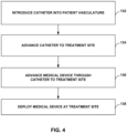
FIG. 4 is a flow diagram illustrating an example method of deploying an example embolization device, such as the example embolization devices described herein. The method includes introducingcatheter 44 into vasculature of a patient (132) and advancingcatheter 44 to target site 46 (FIG. 3 ) within the patient's vasculature (134). Once thedistal end 56 ofcatheter 44 is at the desired position relative to targetsite 46, a clinician may advanceembolization device 10 throughinner lumen 42 of catheter 44 (136) and deployembolization device 10 at target site 46 (138). For example, the clinician may apply a pushing force to trailingend 13 of device body 12 (FIG. 2 ) usingpositioner 45 or another device to deploydevice body 12 frominner lumen 42 and deployembolization device 10 attarget site 46. - Upon deploying
embolization device 10 at the desiredvascular treatment site 46,device body 12 ofembolization device 10 assumes a deployed configuration, e.g., as shown inFIG. 3 . In some examples, the deployed configuration includes afirst section 14 that defines multiple first loops that form a 3D non-helical structure configured to anchordevice body 12 at the treatment site and one or moresecond sections 16 that each defines multiple secondary loops that form a 3D non-helical structure. Further, in some cases eachsecond section 16 has a maximum cross-sectional dimension that is smaller than a maximum cross-sectional dimension offirst section 14. -
Embolization device 10 as well as other embolization devices described herein that includefirst section 14 and one or moresecond sections 16 may be formed using any suitable technique, such as by using a mandrel that includes different rods extending therefrom to define different parts ofembolization device 10. -
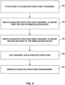
FIG. 5 is a flow diagram illustrating an example method of forming an embolization device, such asexample embolization device 10 shown inFIG. 1 . WhileFIG. 5 is described with reference toembolization device 10, in other examples, the method shown inFIG. 5 may be used to form other embolization device including a first section and one or more second sections, as described herein. In some examples, the method includes attaching an end of an elongated structure (e.g., a wire or a coil) to a mandrel (142). For example, in some cases the elongated structure may be attached to the mandrel by inserting one end of the elongated structure into a starting hole defined by the mandrel. In some cases, the elongated structure may be stretched and wound tightly around part of the mandrel to secure the end of the elongated structure relative to the mandrel. - In some examples, the elongated structure may be a metal wire in a linear configuration or a metal wire formed into a primary coil, such as in the examples shown in
FIG. 2 . Example embolization devices such as those described herein may be formed of any suitable, biocompatible material. In some examples, the elongated structure may be formed from a metal or metal alloy, including platinum, a platinum alloy, palladium, Nitinol, stainless steel and/or any other metal material characterized as having suitable biocompatibility. - As shown in
FIG. 5 , the example method also includes wrapping the elongated structure about the mandrel to definefirst section 14 of embolization device 10 (144). For example, the elongated structure may be wrapped around the mandrel to form multiple first loops that form a 3D non-helical structure in the deployed configuration offirst section 14. The method also includes wrapping the elongated structure about the mandrel, e.g., one or more second winding cores extending from the main shaft of the mandrel, to define one or moresecond sections 16 of embolization device 10 (146). For example, the elongated structure may be wrapped around the mandrel to form multiple secondary loops forming a corresponding 3D non-helical structure in the deployed configuration of thesecond sections 16. - After wrapping the elongated structure around the mandrel, the mandrel and the elongated structure may be heated (148) and the resulting structure remove from the mandrel (150).
- In some examples, the method shown in
FIG. 5 also includes forming a third section ofembolization device 10, such as by wrapping the elongated structure about the mandrel 90 to define form multiple third loops that are part of a tapered helical structure. - In some examples, embolization devices such as those described herein may include an elongated structure, e.g., a primary coil, that includes wires of different sizes. As an example, in some cases a primary coil may be formed with two wires of different diameters or a single wire with sections having different diameters. In some examples, a leading section of a primary coil may be formed from a wire with a larger diameter than the diameter of a wire forming a trailing section of the primary coil. In some examples, a leading section of a primary coil may be formed from a wire with a smaller diameter than the diameter of a wire forming a trailing section of the primary coil.
- According to some examples, embolization devices as described herein may include one or more fibers. For example, a device may include multiple fibers, at least one bundle of fibers, or multiple fiber bundles. In some examples the fiber(s) can be enlaced, tied, or knotted to a number of places on the embolization device. In some examples the fibers or fiber bundles may be disposed so that they are not tied or knotted to the device, thereby avoiding potentially obstructive bundles that might hinder deployment of the device. In some examples one or more fibers may be nonabsorbable. Example materials that may be used include, but are not limited to, nylon, polyethylene, and/or polypropylene. In some examples, one or more fibers may be bioabsorbable. Example bioabsorbable materials that may be used include, but are not limited to, polyglycolic acid (PGA), polylactic acid (PLA), PGLA, and/or polydioxanone (PDO).
- It should be understood that various aspects disclosed herein may be combined in different combinations than the combinations specifically presented in the description and accompanying drawings. It should also be understood that, depending on the example, certain acts or events of any of the processes or methods described herein may be performed in a different sequence, may be added, merged, or left out altogether (e.g., all described acts or events may not be necessary to carry out the techniques). In addition, while certain aspects of this disclosure are described as being performed by a single module or unit for purposes of clarity, it should be understood that the techniques of this disclosure may be performed by a combination of units or modules associated with, for example, a medical device.
Claims (10)
- A medical device (10) for embolizing a vascular site comprising:
a device body (12) comprising a first section (14) and at least one second section (16), wherein, in a deployed configuration of the device body:the first section defines a plurality of first loops (18) forming a three-dimensional non-helical structure configured to anchor the device body in vasculature of a patient,each second section defines a plurality of secondary loops (18) forming a three-dimensional non-helical structure, andeach second section has a maximum cross-sectional dimension that is smaller than a maximum cross-sectional dimension of the first section, characterized in that the three-dimensional non-helical structure of the first section and the three-dimensional non-helical structure of each of the one or more second sections is approximately polyhedral. - The medical device of claim 1, wherein the device body comprises a plurality of second sections.
- The medical device of claim 1 or claim 2, wherein the device body comprises a coil comprising a plurality of windings.
- The medical device of any of claims 1 to 3, wherein the maximum cross-sectional dimension of the first section is from about 10% to about 50% larger than the maximum cross-sectional dimension of each second section.
- The medical device of any of claims 1 to 4, wherein the device body is configured for a nominal vessel size, wherein the maximum cross-sectional dimension of the first section is about 1.1 to about 2.0 times larger than the nominal vessel size, and wherein the nominal vessel size is about 1.0 to about 1.1 times larger than the maximum cross-sectional dimension of each second section.
- The medical device of any of claims 1 to 5, wherein the device body further comprises a third section (30) connected to the first section, wherein in the deployed configuration, the third section defines a plurality of third loops forming a helical structure configured to anchor the device body in the vasculature of the patient.
- The medical device of claim 6, wherein the helical structure has a tapered configuration and preferably, wherein the tapered configuration increases in diameter toward the first section.
- An assembly comprising:a catheter (44) defining an inner lumen; andthe medical device of any of claims 1-7 and 10 positioned within the inner lumen in a delivery configuration, wherein the medical device is configured to expand from the delivery configuration to the deployed configuration in response to being deployed from the inner lumen of the catheter.
- The assembly of claim 8, wherein in the delivery configuration of the medical device, the device body comprises a substantially linear configuration within the inner lumen.
- The medical device of claims 1-7, wherein each of the one or more second sections trails the first section.
Applications Claiming Priority (2)
| Application Number | Priority Date | Filing Date | Title |
|---|---|---|---|
| US16/539,575 US11399840B2 (en) | 2019-08-13 | 2019-08-13 | Implantable embolization device |
| PCT/US2020/042352 WO2021030004A1 (en) | 2019-08-13 | 2020-07-16 | Implantable embolization device |
Publications (2)
| Publication Number | Publication Date |
|---|---|
| EP4013316A1 EP4013316A1 (en) | 2022-06-22 |
| EP4013316B1 true EP4013316B1 (en) | 2025-04-16 |
Family
ID=71995101
Family Applications (1)
| Application Number | Title | Priority Date | Filing Date |
|---|---|---|---|
| EP20753560.0A Active EP4013316B1 (en) | 2019-08-13 | 2020-07-16 | Implantable embolization device |
Country Status (4)
| Country | Link |
|---|---|
| US (4) | US11399840B2 (en) |
| EP (1) | EP4013316B1 (en) |
| CN (1) | CN114206234B (en) |
| WO (1) | WO2021030004A1 (en) |
Families Citing this family (6)
| Publication number | Priority date | Publication date | Assignee | Title |
|---|---|---|---|---|
| US11399840B2 (en) * | 2019-08-13 | 2022-08-02 | Covidien Lp | Implantable embolization device |
| EP4181798B1 (en) * | 2020-08-18 | 2025-10-29 | Balt Usa, Llc | Vascular embolic implant |
| CN112826563B (en) * | 2021-03-02 | 2025-06-17 | 微创神通医疗科技(上海)有限公司 | Medical implant and method of manufacturing the same |
| CN113288315A (en) * | 2021-06-21 | 2021-08-24 | 上海鸿脉医疗科技有限公司 | Medical implant and manufacturing method thereof |
| US20240016497A1 (en) * | 2022-07-12 | 2024-01-18 | Medtronic Inc. | Implantable embolization device |
| WO2025029750A1 (en) * | 2023-07-28 | 2025-02-06 | Balt Innovation Sas | Multi-sectional implant for vascular treatment |
Citations (9)
| Publication number | Priority date | Publication date | Assignee | Title |
|---|---|---|---|---|
| WO2006053107A1 (en) | 2004-11-09 | 2006-05-18 | Boston Scientific Limited | Vaso-occlusive devices comprising complex-shape proximal portion and smaller diameter distal portion |
| US20080319532A1 (en) | 2004-09-22 | 2008-12-25 | Ev3, Inc. | Medical Implant |
| US20140128907A1 (en) | 2011-09-30 | 2014-05-08 | Penumbra, Inc. | Occlusive coil |
| US20170105738A1 (en) | 2014-05-19 | 2017-04-20 | Kaneka Corporation | In vivo indwelling member and method for producing same |
| JP2017099871A (en) | 2015-11-19 | 2017-06-08 | 株式会社カネカ | Mandrel and method for producing in-vivo indwelling member using the mandrel |
| WO2017193375A1 (en) | 2016-05-13 | 2017-11-16 | Covidien Lp | Aneurysm treatment coils |
| US20180263633A1 (en) | 2015-11-19 | 2018-09-20 | Kaneka Corporation | In vivo indwelling member, and in vivo indwelling member placement device provided with said in vivo indwelling member |
| EP3378415A1 (en) * | 2015-11-19 | 2018-09-26 | Kaneka Corporation | In vivo indwelling member, and in vivo indwelling member placement device provided with said in vivo indwelling member |
| CN108814669A (en) | 2018-10-09 | 2018-11-16 | 微创神通医疗科技(上海)有限公司 | Embolization device and its spring ring |
Family Cites Families (56)
| Publication number | Priority date | Publication date | Assignee | Title |
|---|---|---|---|---|
| US4994069A (en) | 1988-11-02 | 1991-02-19 | Target Therapeutics | Vaso-occlusion coil and method |
| DE4104702C2 (en) | 1991-02-15 | 1996-01-18 | Malte Neuss | Implants for organ pathways in spiral form |
| US5382259A (en) | 1992-10-26 | 1995-01-17 | Target Therapeutics, Inc. | Vasoocclusion coil with attached tubular woven or braided fibrous covering |
| US6117157A (en) | 1994-03-18 | 2000-09-12 | Cook Incorporated | Helical embolization coil |
| US6638291B1 (en) | 1995-04-20 | 2003-10-28 | Micrus Corporation | Three dimensional, low friction vasoocclusive coil, and method of manufacture |
| NO962336L (en) | 1995-06-06 | 1996-12-09 | Target Therapeutics Inc | Vaso-occlusive spiral |
| US5649949A (en) | 1996-03-14 | 1997-07-22 | Target Therapeutics, Inc. | Variable cross-section conical vasoocclusive coils |
| GB9614950D0 (en) | 1996-07-16 | 1996-09-04 | Anson Medical Ltd | A ductus stent and delivery catheter |
| US5733329A (en) | 1996-12-30 | 1998-03-31 | Target Therapeutics, Inc. | Vaso-occlusive coil with conical end |
| US5800454A (en) | 1997-03-17 | 1998-09-01 | Sarcos, Inc. | Catheter deliverable coiled wire thromboginic apparatus and method |
| US6156061A (en) | 1997-08-29 | 2000-12-05 | Target Therapeutics, Inc. | Fast-detaching electrically insulated implant |
| US6860893B2 (en) | 1997-08-29 | 2005-03-01 | Boston Scientific Scimed, Inc. | Stable coil designs |
| AU6288799A (en) | 1998-10-09 | 2000-05-01 | Cook Incorporated | Vasoocclusion coil device having a core therein |
| US6280457B1 (en) | 1999-06-04 | 2001-08-28 | Scimed Life Systems, Inc. | Polymer covered vaso-occlusive devices and methods of producing such devices |
| US6790218B2 (en) | 1999-12-23 | 2004-09-14 | Swaminathan Jayaraman | Occlusive coil manufacture and delivery |
| US7033374B2 (en) | 2000-09-26 | 2006-04-25 | Microvention, Inc. | Microcoil vaso-occlusive device with multi-axis secondary configuration |
| US7029486B2 (en) * | 2000-09-26 | 2006-04-18 | Microvention, Inc. | Microcoil vaso-occlusive device with multi-axis secondary configuration |
| US6793665B2 (en) * | 2001-06-18 | 2004-09-21 | Rex Medical, L.P. | Multiple access vein filter |
| US20040098023A1 (en) | 2002-11-15 | 2004-05-20 | Scimed Life Systems, Inc. | Embolic device made of nanofibers |
| US8043321B2 (en) | 2003-07-24 | 2011-10-25 | Boston Scientific Scimed, Inc. | Embolic coil |
| US7645292B2 (en) | 2003-10-27 | 2010-01-12 | Boston Scientific Scimed, Inc. | Vaso-occlusive devices with in-situ stiffening elements |
| US20050090856A1 (en) | 2003-10-27 | 2005-04-28 | Scimed Life Systems, Inc. | Vasco-occlusive devices with bioactive elements |
| US20050107823A1 (en) | 2003-11-19 | 2005-05-19 | Leone Jim E. | Anchored stent and occlusive device for treatment of aneurysms |
| US7485123B2 (en) | 2004-03-01 | 2009-02-03 | Boston Scientific Scimed, Inc. | Complex vaso-occlusive coils |
| US7488332B2 (en) | 2004-03-01 | 2009-02-10 | Boston Scientific Scimed, Inc. | Vaso-occlusive coils with non-overlapping sections |
| US20060206200A1 (en) | 2004-05-25 | 2006-09-14 | Chestnut Medical Technologies, Inc. | Flexible vascular occluding device |
| US20060095071A1 (en) | 2004-11-01 | 2006-05-04 | Zhang Ping Y | Ebolic apparatus and methods for tumor vasculture system obstruction |
| EP1883371B1 (en) | 2005-05-25 | 2015-10-07 | Covidien LP | System and method for delivering and deploying and occluding device within a vessel |
| US8007509B2 (en) | 2005-10-12 | 2011-08-30 | Boston Scientific Scimed, Inc. | Coil assemblies, components and methods |
| EP1973680B1 (en) | 2005-11-17 | 2018-01-10 | Microvention, Inc. | Three-dimensional complex coil |
| US20070162108A1 (en) | 2005-12-13 | 2007-07-12 | Carlson James M | Implantable medical device using palladium |
| US20070299461A1 (en) | 2006-06-21 | 2007-12-27 | Boston Scientific Scimed, Inc. | Embolic coils and related components, systems, and methods |
| JP5179089B2 (en) | 2006-07-28 | 2013-04-10 | テルモ株式会社 | Medical long body |
| EP2124762B1 (en) | 2007-03-13 | 2013-09-11 | Covidien LP | An implant including a coil and a stretch-resistant member |
| WO2008112436A2 (en) | 2007-03-13 | 2008-09-18 | Micro Therapeutics, Inc. | An implant, a mandrel, and a method of forming an implant |
| US20100010533A1 (en) * | 2008-07-11 | 2010-01-14 | Cook Incorporated | Variable strength embolization coil |
| US9089405B1 (en) | 2008-09-12 | 2015-07-28 | Microvention, Inc. | Three-dimensional complex coil |
| EP2493367B1 (en) | 2009-10-26 | 2019-03-13 | Microvention, Inc. | Embolization device constructed from expansile polymer |
| BR112013029013B1 (en) | 2011-05-11 | 2021-03-30 | Microvention, Inc | OCCLUSION DEVICE |
| EP2707077B1 (en) | 2011-05-11 | 2017-10-04 | Microvention, Inc. | Device for occluding a lumen |
| US10342548B2 (en) | 2012-01-13 | 2019-07-09 | W. L. Gore & Associates, Inc. | Occlusion devices and methods of their manufacture and use |
| CA2862232C (en) | 2012-01-17 | 2019-09-24 | Endoshape, Inc. | Occlusion device for a vascular or biological lumen |
| US9687245B2 (en) | 2012-03-23 | 2017-06-27 | Covidien Lp | Occlusive devices and methods of use |
| US11224437B2 (en) | 2014-01-14 | 2022-01-18 | Penumbra, Inc. | Soft embolic implant |
| US10595875B2 (en) * | 2014-12-31 | 2020-03-24 | Endostream Medical Ltd. | Device for restricting blood flow to aneurysms |
| US10857012B2 (en) | 2015-01-20 | 2020-12-08 | Neurogami Medical, Inc. | Vascular implant |
| US10869673B2 (en) | 2015-02-05 | 2020-12-22 | Boston Scientific Scimed, Inc. | Embolic coil with kick-in tail |
| US10307168B2 (en) | 2015-08-07 | 2019-06-04 | Terumo Corporation | Complex coil and manufacturing techniques |
| ES2972442T3 (en) | 2015-09-04 | 2024-06-12 | Texas A & M Univ Sys | Shape Memory Polymer Vascular Occlusion Device |
| US20170189033A1 (en) | 2016-01-06 | 2017-07-06 | Microvention, Inc. | Occlusive Embolic Coil |
| US10478195B2 (en) | 2016-08-04 | 2019-11-19 | Covidien Lp | Devices, systems, and methods for the treatment of vascular defects |
| WO2018053314A1 (en) | 2016-09-16 | 2018-03-22 | Greg Mirigian | Occlusive implants with fiber-based release structures |
| US10842607B2 (en) | 2016-10-14 | 2020-11-24 | Microvention, Inc. | Embolic coils |
| ES2967415T3 (en) | 2016-10-21 | 2024-04-30 | Javelin Medical Ltd | Embolic protection devices |
| CN109223084A (en) * | 2018-09-17 | 2019-01-18 | 南京思脉德医疗科技有限公司 | A kind of more handles concatenation shape embolism spring rings of more balls |
| US11399840B2 (en) * | 2019-08-13 | 2022-08-02 | Covidien Lp | Implantable embolization device |
-
2019
- 2019-08-13 US US16/539,575 patent/US11399840B2/en active Active
-
2020
- 2020-07-16 EP EP20753560.0A patent/EP4013316B1/en active Active
- 2020-07-16 WO PCT/US2020/042352 patent/WO2021030004A1/en not_active Ceased
- 2020-07-16 CN CN202080056900.1A patent/CN114206234B/en active Active
-
2022
- 2022-07-19 US US17/813,469 patent/US11944313B2/en active Active
-
2024
- 2024-02-27 US US18/588,797 patent/US12396731B2/en active Active
-
2025
- 2025-07-24 US US19/279,175 patent/US20250345063A1/en active Pending
Patent Citations (10)
| Publication number | Priority date | Publication date | Assignee | Title |
|---|---|---|---|---|
| US20080319532A1 (en) | 2004-09-22 | 2008-12-25 | Ev3, Inc. | Medical Implant |
| WO2006053107A1 (en) | 2004-11-09 | 2006-05-18 | Boston Scientific Limited | Vaso-occlusive devices comprising complex-shape proximal portion and smaller diameter distal portion |
| US20140128907A1 (en) | 2011-09-30 | 2014-05-08 | Penumbra, Inc. | Occlusive coil |
| US20170105738A1 (en) | 2014-05-19 | 2017-04-20 | Kaneka Corporation | In vivo indwelling member and method for producing same |
| JP2017099871A (en) | 2015-11-19 | 2017-06-08 | 株式会社カネカ | Mandrel and method for producing in-vivo indwelling member using the mandrel |
| US20180263633A1 (en) | 2015-11-19 | 2018-09-20 | Kaneka Corporation | In vivo indwelling member, and in vivo indwelling member placement device provided with said in vivo indwelling member |
| EP3378415A1 (en) * | 2015-11-19 | 2018-09-26 | Kaneka Corporation | In vivo indwelling member, and in vivo indwelling member placement device provided with said in vivo indwelling member |
| WO2017193375A1 (en) | 2016-05-13 | 2017-11-16 | Covidien Lp | Aneurysm treatment coils |
| CN108814669A (en) | 2018-10-09 | 2018-11-16 | 微创神通医疗科技(上海)有限公司 | Embolization device and its spring ring |
| EP3858263A1 (en) | 2018-10-09 | 2021-08-04 | MicroPort NeuroTech (Shanghai) Co., Ltd. | Embolism device and spring coils thereof |
Non-Patent Citations (2)
| Title |
|---|
| HIGASHIDA R.T., COGNARD C., BRACARD S.: "Initial Clinical Experience with a New Complex-Shaped Detachable Platinum Coil System for the Treatment of Intracranial Cerebral Aneurysms : The Cordis Trufill DCS Detachable Coil System", INTERVENTIONAL NEURORADIOLOGY : JOURNAL OF PERITHERAPEUTIC NEURORADIOLOGY, SURGICAL PROCEDURES AND RELATED NEUROSCIENCES, ED. DEL CENTAURO, IT, vol. 12, no. 2, 1 June 2006 (2006-06-01), IT , pages 123 - 130, XP093361143, ISSN: 1591-0199, DOI: 10.1177/159101990601200206 |
| VAN ROOIJ W.J, SLUZEWSKI M: "Packing Performance of GDC 360{degrees} Coils in Intracranial Aneurysms: A Comparison with Complex Orbit Coils and Helical GDC 10 Coils", AMERICAN JOURNAL OF NEURORADIOLOGY, AMERICAN SOCIETY OF NEURORADIOLOGY, US, vol. 28, no. 2, 1 February 2007 (2007-02-01), US , pages 368 - 370, XP093361145, ISSN: 0195-6108 |
Also Published As
| Publication number | Publication date |
|---|---|
| US12396731B2 (en) | 2025-08-26 |
| WO2021030004A1 (en) | 2021-02-18 |
| CN114206234A (en) | 2022-03-18 |
| US20250345063A1 (en) | 2025-11-13 |
| EP4013316A1 (en) | 2022-06-22 |
| US20220346802A1 (en) | 2022-11-03 |
| US20240197330A1 (en) | 2024-06-20 |
| US11944313B2 (en) | 2024-04-02 |
| US20210045749A1 (en) | 2021-02-18 |
| CN114206234B (en) | 2026-03-17 |
| US11399840B2 (en) | 2022-08-02 |
Similar Documents
| Publication | Publication Date | Title |
|---|---|---|
| EP4013316B1 (en) | Implantable embolization device | |
| US12226102B2 (en) | Devices for therapeutic vascular procedures | |
| US12396733B2 (en) | Device for restricting blood flow to aneurysms | |
| CN106073848B (en) | Expandable Vascular Occlusion Device with Lead Frame Coil | |
| JP6392312B2 (en) | Continuous embolic coil and method and device for delivering the same | |
| US20120071911A1 (en) | Spherical helix embolic coils for the treatment of cerebral aneurysms | |
| EP2926744A1 (en) | Improved aneurysm occlusion device | |
| WO2015160721A1 (en) | Devices for therapeutic vascular procedures | |
| US20180317933A1 (en) | Devices and Methods for Treatment of Endovascular and Non-Endovascular Defects in Humans | |
| US20180221030A1 (en) | Devices and Methods for Treatment of Endovascular and Non-Endovascular Defects in Humans Using Tandem Embolization Devices | |
| US20240016497A1 (en) | Implantable embolization device | |
| JP2022159143A (en) | Bio-absorbable coiled fiber |
Legal Events
| Date | Code | Title | Description |
|---|---|---|---|
| STAA | Information on the status of an ep patent application or granted ep patent |
Free format text: STATUS: UNKNOWN |
|
| STAA | Information on the status of an ep patent application or granted ep patent |
Free format text: STATUS: THE INTERNATIONAL PUBLICATION HAS BEEN MADE |
|
| PUAI | Public reference made under article 153(3) epc to a published international application that has entered the european phase |
Free format text: ORIGINAL CODE: 0009012 |
|
| STAA | Information on the status of an ep patent application or granted ep patent |
Free format text: STATUS: REQUEST FOR EXAMINATION WAS MADE |
|
| 17P | Request for examination filed |
Effective date: 20220217 |
|
| AK | Designated contracting states |
Kind code of ref document: A1 Designated state(s): AL AT BE BG CH CY CZ DE DK EE ES FI FR GB GR HR HU IE IS IT LI LT LU LV MC MK MT NL NO PL PT RO RS SE SI SK SM TR |
|
| DAV | Request for validation of the european patent (deleted) | ||
| DAX | Request for extension of the european patent (deleted) | ||
| GRAP | Despatch of communication of intention to grant a patent |
Free format text: ORIGINAL CODE: EPIDOSNIGR1 |
|
| STAA | Information on the status of an ep patent application or granted ep patent |
Free format text: STATUS: GRANT OF PATENT IS INTENDED |
|
| INTG | Intention to grant announced |
Effective date: 20241128 |
|
| GRAS | Grant fee paid |
Free format text: ORIGINAL CODE: EPIDOSNIGR3 |
|
| GRAA | (expected) grant |
Free format text: ORIGINAL CODE: 0009210 |
|
| STAA | Information on the status of an ep patent application or granted ep patent |
Free format text: STATUS: THE PATENT HAS BEEN GRANTED |
|
| AK | Designated contracting states |
Kind code of ref document: B1 Designated state(s): AL AT BE BG CH CY CZ DE DK EE ES FI FR GB GR HR HU IE IS IT LI LT LU LV MC MK MT NL NO PL PT RO RS SE SI SK SM TR |
|
| REG | Reference to a national code |
Ref country code: GB Ref legal event code: FG4D |
|
| REG | Reference to a national code |
Ref country code: CH Ref legal event code: EP Ref country code: DE Ref legal event code: R096 Ref document number: 602020049558 Country of ref document: DE |
|
| REG | Reference to a national code |
Ref country code: IE Ref legal event code: FG4D |
|
| PGFP | Annual fee paid to national office [announced via postgrant information from national office to epo] |
Ref country code: FR Payment date: 20250620 Year of fee payment: 6 |
|
| REG | Reference to a national code |
Ref country code: NL Ref legal event code: MP Effective date: 20250416 |
|
| PG25 | Lapsed in a contracting state [announced via postgrant information from national office to epo] |
Ref country code: NL Free format text: LAPSE BECAUSE OF FAILURE TO SUBMIT A TRANSLATION OF THE DESCRIPTION OR TO PAY THE FEE WITHIN THE PRESCRIBED TIME-LIMIT Effective date: 20250416 |
|
| REG | Reference to a national code |
Ref country code: AT Ref legal event code: MK05 Ref document number: 1784990 Country of ref document: AT Kind code of ref document: T Effective date: 20250416 |
|
| PG25 | Lapsed in a contracting state [announced via postgrant information from national office to epo] |
Ref country code: FI Free format text: LAPSE BECAUSE OF FAILURE TO SUBMIT A TRANSLATION OF THE DESCRIPTION OR TO PAY THE FEE WITHIN THE PRESCRIBED TIME-LIMIT Effective date: 20250416 Ref country code: ES Free format text: LAPSE BECAUSE OF FAILURE TO SUBMIT A TRANSLATION OF THE DESCRIPTION OR TO PAY THE FEE WITHIN THE PRESCRIBED TIME-LIMIT Effective date: 20250416 Ref country code: PT Free format text: LAPSE BECAUSE OF FAILURE TO SUBMIT A TRANSLATION OF THE DESCRIPTION OR TO PAY THE FEE WITHIN THE PRESCRIBED TIME-LIMIT Effective date: 20250818 |
|
| PGFP | Annual fee paid to national office [announced via postgrant information from national office to epo] |
Ref country code: DE Payment date: 20250620 Year of fee payment: 6 |
|
| REG | Reference to a national code |
Ref country code: LT Ref legal event code: MG9D |
|
| PG25 | Lapsed in a contracting state [announced via postgrant information from national office to epo] |
Ref country code: NO Free format text: LAPSE BECAUSE OF FAILURE TO SUBMIT A TRANSLATION OF THE DESCRIPTION OR TO PAY THE FEE WITHIN THE PRESCRIBED TIME-LIMIT Effective date: 20250716 Ref country code: GR Free format text: LAPSE BECAUSE OF FAILURE TO SUBMIT A TRANSLATION OF THE DESCRIPTION OR TO PAY THE FEE WITHIN THE PRESCRIBED TIME-LIMIT Effective date: 20250717 |
|
| PG25 | Lapsed in a contracting state [announced via postgrant information from national office to epo] |
Ref country code: PL Free format text: LAPSE BECAUSE OF FAILURE TO SUBMIT A TRANSLATION OF THE DESCRIPTION OR TO PAY THE FEE WITHIN THE PRESCRIBED TIME-LIMIT Effective date: 20250416 |
|
| PG25 | Lapsed in a contracting state [announced via postgrant information from national office to epo] |
Ref country code: BG Free format text: LAPSE BECAUSE OF FAILURE TO SUBMIT A TRANSLATION OF THE DESCRIPTION OR TO PAY THE FEE WITHIN THE PRESCRIBED TIME-LIMIT Effective date: 20250416 |
|
| PG25 | Lapsed in a contracting state [announced via postgrant information from national office to epo] |
Ref country code: HR Free format text: LAPSE BECAUSE OF FAILURE TO SUBMIT A TRANSLATION OF THE DESCRIPTION OR TO PAY THE FEE WITHIN THE PRESCRIBED TIME-LIMIT Effective date: 20250416 |
|
| PG25 | Lapsed in a contracting state [announced via postgrant information from national office to epo] |
Ref country code: AT Free format text: LAPSE BECAUSE OF FAILURE TO SUBMIT A TRANSLATION OF THE DESCRIPTION OR TO PAY THE FEE WITHIN THE PRESCRIBED TIME-LIMIT Effective date: 20250416 |
|
| PG25 | Lapsed in a contracting state [announced via postgrant information from national office to epo] |
Ref country code: RS Free format text: LAPSE BECAUSE OF FAILURE TO SUBMIT A TRANSLATION OF THE DESCRIPTION OR TO PAY THE FEE WITHIN THE PRESCRIBED TIME-LIMIT Effective date: 20250716 |
|
| PG25 | Lapsed in a contracting state [announced via postgrant information from national office to epo] |
Ref country code: IS Free format text: LAPSE BECAUSE OF FAILURE TO SUBMIT A TRANSLATION OF THE DESCRIPTION OR TO PAY THE FEE WITHIN THE PRESCRIBED TIME-LIMIT Effective date: 20250816 |
|
| PG25 | Lapsed in a contracting state [announced via postgrant information from national office to epo] |
Ref country code: LV Free format text: LAPSE BECAUSE OF FAILURE TO SUBMIT A TRANSLATION OF THE DESCRIPTION OR TO PAY THE FEE WITHIN THE PRESCRIBED TIME-LIMIT Effective date: 20250416 |
|
| PG25 | Lapsed in a contracting state [announced via postgrant information from national office to epo] |
Ref country code: DK Free format text: LAPSE BECAUSE OF FAILURE TO SUBMIT A TRANSLATION OF THE DESCRIPTION OR TO PAY THE FEE WITHIN THE PRESCRIBED TIME-LIMIT Effective date: 20250416 Ref country code: SM Free format text: LAPSE BECAUSE OF FAILURE TO SUBMIT A TRANSLATION OF THE DESCRIPTION OR TO PAY THE FEE WITHIN THE PRESCRIBED TIME-LIMIT Effective date: 20250416 |
|
| REG | Reference to a national code |
Ref country code: DE Ref legal event code: R026 Ref document number: 602020049558 Country of ref document: DE |
|
| PG25 | Lapsed in a contracting state [announced via postgrant information from national office to epo] |
Ref country code: CZ Free format text: LAPSE BECAUSE OF FAILURE TO SUBMIT A TRANSLATION OF THE DESCRIPTION OR TO PAY THE FEE WITHIN THE PRESCRIBED TIME-LIMIT Effective date: 20250416 |
|
| PLBI | Opposition filed |
Free format text: ORIGINAL CODE: 0009260 |
|
| PG25 | Lapsed in a contracting state [announced via postgrant information from national office to epo] |
Ref country code: EE Free format text: LAPSE BECAUSE OF FAILURE TO SUBMIT A TRANSLATION OF THE DESCRIPTION OR TO PAY THE FEE WITHIN THE PRESCRIBED TIME-LIMIT Effective date: 20250416 |
|
| PG25 | Lapsed in a contracting state [announced via postgrant information from national office to epo] |
Ref country code: SK Free format text: LAPSE BECAUSE OF FAILURE TO SUBMIT A TRANSLATION OF THE DESCRIPTION OR TO PAY THE FEE WITHIN THE PRESCRIBED TIME-LIMIT Effective date: 20250416 Ref country code: RO Free format text: LAPSE BECAUSE OF FAILURE TO SUBMIT A TRANSLATION OF THE DESCRIPTION OR TO PAY THE FEE WITHIN THE PRESCRIBED TIME-LIMIT Effective date: 20250416 |
|
| PG25 | Lapsed in a contracting state [announced via postgrant information from national office to epo] |
Ref country code: IT Free format text: LAPSE BECAUSE OF FAILURE TO SUBMIT A TRANSLATION OF THE DESCRIPTION OR TO PAY THE FEE WITHIN THE PRESCRIBED TIME-LIMIT Effective date: 20250416 |
|
| PLAX | Notice of opposition and request to file observation + time limit sent |
Free format text: ORIGINAL CODE: EPIDOSNOBS2 |
|
| REG | Reference to a national code |
Ref country code: CH Ref legal event code: L10 Free format text: ST27 STATUS EVENT CODE: U-0-0-L10-L00 (AS PROVIDED BY THE NATIONAL OFFICE) Effective date: 20260128 |
|
| REG | Reference to a national code |
Ref country code: CH Ref legal event code: H13 Free format text: ST27 STATUS EVENT CODE: U-0-0-H10-H13 (AS PROVIDED BY THE NATIONAL OFFICE) Effective date: 20260224 |
|
| 26 | Opposition filed |
Opponent name: JAMES POOLE LIMITED Effective date: 20260116 |
|
| PG25 | Lapsed in a contracting state [announced via postgrant information from national office to epo] |
Ref country code: LU Free format text: LAPSE BECAUSE OF NON-PAYMENT OF DUE FEES Effective date: 20250716 |
|
| GBPC | Gb: european patent ceased through non-payment of renewal fee |
Effective date: 20250716 |
|
| REG | Reference to a national code |
Ref country code: BE Ref legal event code: MM Effective date: 20250731 |
|
| PG25 | Lapsed in a contracting state [announced via postgrant information from national office to epo] |
Ref country code: GB Free format text: LAPSE BECAUSE OF NON-PAYMENT OF DUE FEES Effective date: 20250716 |
|
| PG25 | Lapsed in a contracting state [announced via postgrant information from national office to epo] |
Ref country code: BE Free format text: LAPSE BECAUSE OF NON-PAYMENT OF DUE FEES Effective date: 20250731 |