EP4013190A1 - Circuit device for a cooking device, in particular cooking hob, more in particular induction cooking hob and cooking device, in particular cooking hob, more in particular induction cooking hob - Google Patents
Circuit device for a cooking device, in particular cooking hob, more in particular induction cooking hob and cooking device, in particular cooking hob, more in particular induction cooking hob Download PDFInfo
- Publication number
- EP4013190A1 EP4013190A1 EP20213766.7A EP20213766A EP4013190A1 EP 4013190 A1 EP4013190 A1 EP 4013190A1 EP 20213766 A EP20213766 A EP 20213766A EP 4013190 A1 EP4013190 A1 EP 4013190A1
- Authority
- EP
- European Patent Office
- Prior art keywords
- power
- current
- unit
- conversion unit
- phase
- Prior art date
- Legal status (The legal status is an assumption and is not a legal conclusion. Google has not performed a legal analysis and makes no representation as to the accuracy of the status listed.)
- Granted
Links
Images
Classifications
-
- H—ELECTRICITY
- H05—ELECTRIC TECHNIQUES NOT OTHERWISE PROVIDED FOR
- H05B—ELECTRIC HEATING; ELECTRIC LIGHT SOURCES NOT OTHERWISE PROVIDED FOR; CIRCUIT ARRANGEMENTS FOR ELECTRIC LIGHT SOURCES, IN GENERAL
- H05B6/00—Heating by electric, magnetic or electromagnetic fields
- H05B6/02—Induction heating
- H05B6/06—Control, e.g. of temperature, of power
- H05B6/062—Control, e.g. of temperature, of power for cooking plates or the like
-
- H—ELECTRICITY
- H05—ELECTRIC TECHNIQUES NOT OTHERWISE PROVIDED FOR
- H05B—ELECTRIC HEATING; ELECTRIC LIGHT SOURCES NOT OTHERWISE PROVIDED FOR; CIRCUIT ARRANGEMENTS FOR ELECTRIC LIGHT SOURCES, IN GENERAL
- H05B1/00—Details of electric heating devices
- H05B1/02—Automatic switching arrangements specially adapted to apparatus ; Control of heating devices
- H05B1/0227—Applications
- H05B1/0252—Domestic applications
- H05B1/0258—For cooking
- H05B1/0261—For cooking of food
- H05B1/0266—Cooktops
Definitions
- the present invention relates to a circuit device for a cooking device, in particular cooking hob, more in particular induction cooking hob and to a cooking device, in particular cooking hob, more in particular induction cooking hob.
- Circuit devices for a cooking device in particular cooking hob, more in particular induction cooking hob, for example induction boards, are supplied from mains current (or: AC grid voltage), by a single current/voltage phase or multiple current/voltage phases.
- mains current or: AC grid voltage
- frequency converting means can derive sinusoidal currents for injecting in induction elements, for example coils.
- output direct currents are generated for supplying electronics and for driving frequency converting means, in particular inverters.
- the invention relates, in claim 1, to a circuit device for a cooking device, in particular cooking hob, more in particular induction cooking hob, the circuit device comprising
- the first output direct current or one of the first output direct currents of the first power unit is or can be the second input direct current of the second power unit.
- the first power unit can supply each other power unit with a direct current.
- An input direct current can in particular be a DC input current.
- An input alternating current can in particular be an AC input current.
- An output direct current can in particular be a DC output current.
- An alternating current can in particular be a current which is supplied by an alternating voltage or AC voltage, in particular between 100V and 250V or between 85V and 265V, with an input frequency, in particular between 45Hz and 130Hz, more in particular of 50 Hz or 65Hz, as well as a current phase.
- the current conversion unit can in particular be a DC/DC converter which converts a direct input voltage into one or more direct output voltages.
- the current conversion unit can in particular be an AC/DC converter which converts an alternating input voltage into one or more direct output voltages.
- a main current phase can in particular be an alternating current which is supplied with a predefined current phase.
- Such a current phase can be phase-shifted, for example by 120°, to different mains current phases.
- electrical power can be supplied by two or three different current phases which are phase shifted by 120° or 180°.
- a mains current is in particular a current which is supplied by an external power net or supply net.
- a load can in particular be a control unit or a fan.
- a load can in particular be a low power unit which is preferably supplied with power by a supply voltage of 18V or less.
- At least one or each power unit is a power board, in particular mounted as or on a printed circuit board.
- a printed circuit board can allow a good isolation of the different mains current phases.
- the usage of printed circuit boards can allow an efficient pre-mounting of the power units for the different mains current phases.
- At least one or each of the current conversion units is an insulated current conversion unit, in particular an insulated AC/DC conversion unit and/or an insulated DC/DC conversion unit. This enables or can enable a good isolation of the different current phases.
- the first current conversion unit is an AC/DC converter that outputs one, at least one, two or at least two direct voltages, in particular at least two different direct voltages, for example 5V and 18V, and/or currents from the first mains current phase, in particular from a single phase-neutral AC voltage or from a phase-phase AC voltage.
- a phase-phase AC voltage is or can be a typical mains voltage, for example in the United States of America.
- the first current conversion unit in particular by supplying at least a second current conversion unit and/or a third current conversion unit with electrical power, generates supply voltages for multiple loads, in particular for multiple low power loads and/or control units, in particular on at least a second power unit and/or a third power unit or each power unit and/or referred to different mains current phases and/or to different phase-neutral voltages and/or to different phase-phase AC voltages.
- This enables or can enable a power supply for the loads from the first power unit to at least one further power unit.
- At least one of the current conversion units is or are DC/DC conversion units. This enables or can enable simpler and/or less complex current conversion units, as no AC/DC conversion is required in these current conversion units.
- each power unit comprises at least one or only a single current conversion unit, in particular at least one or a single low power current conversion unit, for supplying currents and/or voltages to the loads, in particular the low power loads. This enables or can enable less current conversion units, as no further current conversion units are required in these power units.
- only the first current conversion unit is supplied by a mains current phase, and the second current conversion unit and/or third current conversion unit is/are only supplied by the first current conversion unit. This enables or can enable simpler and/or less complex current conversion units, as no AC/DC conversion is required in these current conversion units.
- At least one or each current conversion unit outputs at least two output voltages, in particular two, at least two, three or at least three different output voltages, in particular for supplying different loads. This enables or can enable the power supply of a larger variety of loads.
- the first power unit is electrically connected with each of the other power units, in particular with the second power unit and/or third power unit, for supplying voltages for loads, in particular for low power loads and/or control units, in particular on each power unit and/or power units referred to different mains current phases and/or to different phase-neutral voltages and/or to different phase-phase AC voltages.
- This enables or can enable simpler and/or less complex current conversion units, as no AC/DC conversion is required in these current conversion units.
- the first current conversion unit of the first power unit is electrically connected with the current conversion units of each of the other power units for supplying voltages for all control units, in particular on each power unit and/or on power units referred to different mains current phases and/or to different phase-neutral voltages and/or to different phase-phase AC voltages.
- a control unit is provided to turn-on or turn-off current conversion units, in particular insulated power supplies, of each power unit or of the second power unit and/or the third power unit.
- the total power from the frequency converting means of each mains current phase is limited by a control unit to a predetermined maximum power, which in particular limits the individual power of each frequency converting means to ensure that total power is below the or a rated power of each mains current phase. This enables or can enable the operation of, in particular a single, frequency converting means with a higher power.
- the predetermined maximum power which limits the power of the frequency converting means on each current phase such that that the total power, is below the or a maximum rated power of each current phase.
- the cooking device comprises induction elements, wherein each power unit supplies or is configured to supply at least one induction element, in particular induction coil, with electrical power by a frequency converting means, preferably to generate heating energy for heating a cooking vessel disposed on the induction element or coil.
- each power unit supplies or is configured to supply at least one induction element, in particular induction coil, with electrical power by a frequency converting means, preferably to generate heating energy for heating a cooking vessel disposed on the induction element or coil.
- each power unit by a different current phase, one, at least one, two, at least two, three, at least three, four or at least four frequency converting means are supplied with electrical power.
- each power unit comprises frequency converting means for supplying at least one induction element with electrical power from the mains current phase supplying the power unit with electrical power.
- a frequency converting means is a means or inverter or generator for converting an input current with an input frequency, in particular between 45Hz and 130Hz, more in particular of 50Hz or 65Hz, into an output current with a high frequency, in particular with a frequency between 10kHz and 100kHz. This enables or can enable to provide heating energy to the induction elements.
- a frequency converting means comprises at least one, in particular common, rectifying means and/or, in particular in series, at least one frequency generation means driven with a driving frequency, wherein the driving frequency is supplied with electrical power by a control unit, wherein in particular the control unit is supplied with electrical power by a or the current conversion unit of the power unit.
- the invention relates to a cooking device, in particular cooking hob, more in particular induction cooking hob, with a circuit device according to the invention.
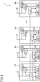
- FIG. 1 shows a circuit device 1 according to an embodiment of the present invention.
- the circuit device 1 is intended for a cooking device, in particular cooking hob, more in particular induction cooking hob.
- the circuit device 1 comprises at least two, in particular two, three or at least three power units P1, P2, .. PN, each power unit supplied with electrical power by a different mains current phase L1, L2, .. LN.
- Each power unit P1, P2, .. PN comprises frequency converting means G11 .. GNM, each for supplying at least one induction element with electrical power to generate heating power.
- Each power unit P1, P2, .. PM comprises at least one current conversion unit C1 .. CN for converting an input direct or alternating current into one, at least one, two or at least two output direct currents.
- Each power unit P1, P2, .. PN comprises at least one load or at least two loads, in particular one or more low-power loads and/or control units, supplied or to be supplied with electrical power by the output direct current, an output direct current or the different output direct currents from the current conversion unit.
- the first power unit P1 comprises a first current conversion unit C1, for converting an alternating current from a first mains current phase L1 into two first output direct currents I11 and 112.
- a second current conversion unit C2 of a second power unit P2 is supplied for converting the first output direct current 112 into two output direct currents 121 and 122.
- one of the first output direct currents is or can be the second input direct current.
- the first power unit P1 can supply each other power unit with a direct current.
- a third current conversion unit C3 of a third power unit P3 is supplied for converting the first output direct current 112 into two output direct currents 131 and 132.
- An input direct current is, for power units P2 and P3, a DC input current.
- An input alternating current is, for power unit P1, an AC input current.
- An output direct current is a DC output current.
- An alternating current can be a current which is supplied by an alternating voltage or AC voltage, in particular between 100V and 250V or between 85V and 265V.
- Each of the current conversion units C2, C3 .. CN is a DC/DC converter which converts a direct input voltage into two direct output voltages.
- the current conversion unit C1 is an AC/DC converter which converts an alternating input voltage L1 into two direct output voltages.
- a main current phase can in particular be an alternating current which is supplied with a predefined current phase.
- Such a current phase can be phase-shifted, for example by 120°, to different mains current phases.
- electrical power can be supplied by two or three different current phases which are phase shifted by 120° or 180°.
- a mains current is a current which is supplied by an external power net or supply net.
- a load can be a control unit or a fan.
- a load can in particular be a low power unit which is preferably supplied with power by a supply voltage of 18V or less.
- Each power unit P1, P2, .. PN is a power board, in particular mounted as or on a printed circuit board.
- a printed circuit board can allow a good isolation of the different mains current phases.
- the usage of printed circuit boards can allow an efficient pre-mounting of the power units for the different mains current phases.
- Each of the current conversion units C1 .. CN is an insulated current conversion unit, in particular an insulated AC/DC conversion unit C1 and insulated DC/DC conversion units C2 .. CN.
- the first current conversion unit C1 is an AC/DC converter that outputs two direct voltages, in particular two different direct voltages, for example 5V and 18V, and currents from the first mains current phase L1, in particular from a single phase-neutral AC voltage or from a phase-phase AC voltage.
- the first current conversion unit C1 by supplying at least a second current conversion unit C2 and a third current conversion unit C3, generates supply voltages for multiple loads, in particular multiple low power loads and/or control units, on at least a second power unit P2 and a third power unit P3 or each power unit P1 .. PN, referred to different mains current phases L1, L2, .. LN and to different phase-neutral voltages and/or to different phase-phase AC voltages.
- At least one of the current conversion units C1 .. CN, in particular the conversion units C2, C3 of the second power unit P2 and a third power unit P3, are DC/DC conversion units.
- Each power unit P1 .. PN comprises at least one or only a single current conversion unit C1 .. CN, in particular at least one or a single low power current conversion unit, for supplying currents and/or voltages to the loads, in particular the low power loads.
- Each current conversion unit C1 .. CN outputs at least two output voltages, in particular two different output voltages, in particular for supplying different loads.
- the first power unit P1 is electrically connected with each of the other power units P2 .. PN, in particular with the second power unit P2 and third power unit P3, for supplying voltages for loads, in particular low power loads and/or control units, on each power unit P1 .. PN and power units referred to different mains current phases L1 .. LN and to different phase-neutral voltages and/or to different phase-phase AC voltages.
- the first current conversion unit of the first power unit is electrically connected with the current conversion units of each of the other power units for supplying voltages for all control units, on each power unit and on power units referred to different mains current phases and to different phase-neutral voltages and/or to different phase-phase AC voltages.
- the circuit device 1 comprises a control unit to turn-on or turn-off current conversion units, in particular insulated power supplies, of each power unit or of the second power unit and/or the third power unit.
- the total power from the frequency converting means G11 .. GNM of each mains current phase L1 .. LN is limited by a control unit to a predetermined maximum power, which limits the individual power of each frequency converting means G11 .. GNM to ensure that total power is below the rated power of each mains current phase L1 .. LN.
- the predetermined maximum power which limits the power of the frequency converting means on each current phase such that the total power, is below the maximum rated power of each current phase.
- the circuit device 1 comprises induction elements, wherein each power unit P1 .. PN supplies or is configured to supply at least one induction element with electrical power by a frequency converting means G1M .. GNM.
- each power unit P1 .. PN by a different current phase L1 .. LN, one, at least one, two, at least two, three, at least three, four or at least four frequency converting means G1M .. GNM are supplied with electrical power.
- Each power unit P1, P2, .. PM comprises frequency converting means G1M .. GNM for supplying at least one induction element with electrical power from the mains current phase L1, L2, .. LM supplying the power unit P1, P2, .. PM with electrical power.
- a frequency converting means G1M .. GNM is a means or generator for converting an input current with an input frequency, in particular between 45Hz and 130Hz, more in particular of 50Hz or of 65Hz, into an output current with a high frequency, in particular with a frequency between 10kHz and 100kHz.
- a frequency converting means G1M .. GNM comprises at least one, in particular common, rectifying means and/or, in particular in series, at least one frequency generation means driven with a driving frequency.
- the driving frequency is supplied with electrical power by a control unit, wherein the control unit is supplied with electrical power by the current conversion unit C1 .. CN of the power unit P1 .. PN.
- the circuit device 1 relates to and/or is part of and/or operates a cooking device, in particular cooking hob, more in particular induction cooking hob, with a circuit device 1.
Landscapes
- Physics & Mathematics (AREA)
- Electromagnetism (AREA)
- Engineering & Computer Science (AREA)
- Food Science & Technology (AREA)
- Ac-Ac Conversion (AREA)
- Inverter Devices (AREA)
- Electric Stoves And Ranges (AREA)
- Cookers (AREA)
Abstract
- at least two, in particular two, three or at least three power units (P1, P2, .. PN), each power unit supplied with electrical power by a different mains current phase (L1, L2, .. LN),
- wherein each power unit (P1, P2, .. PN) comprises frequency converting means (G11 .. GNM), each for supplying at least one induction element with electrical power to generate heating power,
- wherein each power unit (P1, P2, .. PN) comprises at least one current conversion unit (C1 .. CN) for converting an in-put direct or alternating current into one, at least one, two or at least two output direct currents,
- wherein each power unit (P1, P2, .. PN) comprises at least one load or at least two loads, in particular one or more low-power loads and/or control units, supplied or to be sup-plied with electrical power by the output direct current, an output direct current or the output direct currents from the current conversion unit,
- wherein a first power unit (P1) comprises a first current conversion unit (C1), in particular for converting an alternating current from a first mains current phase (L1) into one, at least one, two or at least two first output direct currents (I1),
- wherein by the first output direct current or one of the first output direct currents (I1) of the first power unit (P1), at least a second current conversion unit (C2) of a second power unit (P2) is supplied for converting the first output direct current (I1) into one, at least one, two or at least two second output direct currents.
Description
- The present invention relates to a circuit device for a cooking device, in particular cooking hob, more in particular induction cooking hob and to a cooking device, in particular cooking hob, more in particular induction cooking hob.
- Circuit devices for a cooking device, in particular cooking hob, more in particular induction cooking hob, for example induction boards, are supplied from mains current (or: AC grid voltage), by a single current/voltage phase or multiple current/voltage phases. From phase-neutral voltages, frequency converting means can derive sinusoidal currents for injecting in induction elements, for example coils.
- Furthermore, output direct currents, in particular low DC voltages, are generated for supplying electronics and for driving frequency converting means, in particular inverters.
- Working with multiple current and/or voltage phases causes or can cause the presence of multiple voltage references in the device that can lead to electrical problems, consequently functional electrical insulation must be present between loads, control units or subsystems supplied by different phase voltages.
- It is an object of the invention to provide an improved, and preferably cost effective, simpler and/or flexible, circuit device, which in particular solves at least one or more of the following problems:
- Many electrical components are used for current conversion units, for example AC/DC conversion units, in circuit devices for a cooking device, in particular when supplied by at least two mains current phases.
- The operation of these current conversion units increases or can increase stand-by power consumption.
- Complicated and/or complex EMI (electromagnetic interference) filters are used for each current phase.
- Operation with different mains current phases for small loads and control units prevents electrical insulation
- Complex drivers for frequency converting means, for example generator drivers, are used.
- The object is solved in particular by the circuit device according to
claim 1 and by a cooking device according to claim 15. Improvements are provided in the dependent claims. - The invention relates, in
claim 1, to a circuit device for a cooking device, in particular cooking hob, more in particular induction cooking hob, the circuit device comprising - at least two, in particular two or three or at least three power units, each power unit supplied with electrical power by a different mains current phase,
- wherein each power unit comprises frequency converting means, each for supplying at least one induction element with electrical power to generate heating power,
- wherein each power unit comprises at least one current conversion unit for converting an input direct current or an input alternating current into one, at least one, two or at least two output direct currents,
- wherein each power unit comprises at least one load or at least two loads, in particular one or more low-power loads and/or control units, supplied or to be supplied with electrical power by the output direct current, an output direct current or the output direct currents from the current conversion unit,
- wherein a first power unit comprises a first current conversion unit, in particular for converting an alternating current from a first mains current phase into one, at least one, two or at least two first output direct currents,
- wherein by the first output direct current or one of the first output direct currents of the first power unit, at least a second current conversion unit of a second power unit is supplied for converting the first output direct current into one, at least one, two or at least two second output direct currents.
- By the invention, in particular, at least one or more of the following advantages can be obtained:
- Less electrical components can be used for current conversion units, for example DC/DC conversion units, in circuit devices for a cooking device, in particular when supplied by at least two mains current phases.
- The interruption of the operation of these current conversion units during inactivity decreases or can decrease stand-by power consumption.
- Simpler and/or less complex EMI filters are or can be used for at least some of the current phases.
- Operation with the same mains current phase for small loads and control units enables or can enable electrical insulation.
- Less complex drivers for frequency converting means, for example generator drivers, are or can be used.
- Hence, in particular, the first output direct current or one of the first output direct currents of the first power unit is or can be the second input direct current of the second power unit. Preferably, by the invention, the first power unit can supply each other power unit with a direct current.
- An input direct current can in particular be a DC input current. An input alternating current can in particular be an AC input current. An output direct current can in particular be a DC output current.
- An alternating current can in particular be a current which is supplied by an alternating voltage or AC voltage, in particular between 100V and 250V or between 85V and 265V, with an input frequency, in particular between 45Hz and 130Hz, more in particular of 50 Hz or 65Hz, as well as a current phase.
- The current conversion unit can in particular be a DC/DC converter which converts a direct input voltage into one or more direct output voltages.
- The current conversion unit can in particular be an AC/DC converter which converts an alternating input voltage into one or more direct output voltages.
- A main current phase can in particular be an alternating current which is supplied with a predefined current phase. Such a current phase can be phase-shifted, for example by 120°, to different mains current phases. In particular, electrical power can be supplied by two or three different current phases which are phase shifted by 120° or 180°.
- A mains current is in particular a current which is supplied by an external power net or supply net.
- A load can in particular be a control unit or a fan. A load can in particular be a low power unit which is preferably supplied with power by a supply voltage of 18V or less.
- In particular embodiments, at least one or each power unit is a power board, in particular mounted as or on a printed circuit board.
- A printed circuit board can allow a good isolation of the different mains current phases. The usage of printed circuit boards can allow an efficient pre-mounting of the power units for the different mains current phases.
- In particular embodiments, at least one or each of the current conversion units is an insulated current conversion unit, in particular an insulated AC/DC conversion unit and/or an insulated DC/DC conversion unit. This enables or can enable a good isolation of the different current phases.
- In particular embodiments, the first current conversion unit is an AC/DC converter that outputs one, at least one, two or at least two direct voltages, in particular at least two different direct voltages, for example 5V and 18V, and/or currents from the first mains current phase, in particular from a single phase-neutral AC voltage or from a phase-phase AC voltage. This enables or can enable a direct power supply by the first mains current phase. A phase-phase AC voltage is or can be a typical mains voltage, for example in the United States of America.
- In particular embodiments, the first current conversion unit, in particular by supplying at least a second current conversion unit and/or a third current conversion unit with electrical power, generates supply voltages for multiple loads, in particular for multiple low power loads and/or control units, in particular on at least a second power unit and/or a third power unit or each power unit and/or referred to different mains current phases and/or to different phase-neutral voltages and/or to different phase-phase AC voltages. This enables or can enable a power supply for the loads from the first power unit to at least one further power unit.
- In particular embodiments, at least one of the current conversion units, in particular the or at least one current conversion unit of the second power unit and/or a third power unit, is or are DC/DC conversion units. This enables or can enable simpler and/or less complex current conversion units, as no AC/DC conversion is required in these current conversion units.
- In particular embodiments, each power unit comprises at least one or only a single current conversion unit, in particular at least one or a single low power current conversion unit, for supplying currents and/or voltages to the loads, in particular the low power loads. This enables or can enable less current conversion units, as no further current conversion units are required in these power units.
- In particular embodiments, only the first current conversion unit is supplied by a mains current phase, and the second current conversion unit and/or third current conversion unit is/are only supplied by the first current conversion unit. This enables or can enable simpler and/or less complex current conversion units, as no AC/DC conversion is required in these current conversion units.
- In particular embodiments, at least one or each current conversion unit outputs at least two output voltages, in particular two, at least two, three or at least three different output voltages, in particular for supplying different loads. This enables or can enable the power supply of a larger variety of loads.
- In particular embodiments, the first power unit is electrically connected with each of the other power units, in particular with the second power unit and/or third power unit, for supplying voltages for loads, in particular for low power loads and/or control units, in particular on each power unit and/or power units referred to different mains current phases and/or to different phase-neutral voltages and/or to different phase-phase AC voltages. This enables or can enable simpler and/or less complex current conversion units, as no AC/DC conversion is required in these current conversion units.
- In particular embodiments, the first current conversion unit of the first power unit is electrically connected with the current conversion units of each of the other power units for supplying voltages for all control units, in particular on each power unit and/or on power units referred to different mains current phases and/or to different phase-neutral voltages and/or to different phase-phase AC voltages.
- In particular embodiments, a control unit is provided to turn-on or turn-off current conversion units, in particular insulated power supplies, of each power unit or of the second power unit and/or the third power unit.
- In particular embodiments, the total power from the frequency converting means of each mains current phase is limited by a control unit to a predetermined maximum power, which in particular limits the individual power of each frequency converting means to ensure that total power is below the or a rated power of each mains current phase. This enables or can enable the operation of, in particular a single, frequency converting means with a higher power.
- In particular embodiments, the predetermined maximum power, which limits the power of the frequency converting means on each current phase such that that the total power, is below the or a maximum rated power of each current phase.
- In particular embodiments, the cooking device comprises induction elements, wherein each power unit supplies or is configured to supply at least one induction element, in particular induction coil, with electrical power by a frequency converting means, preferably to generate heating energy for heating a cooking vessel disposed on the induction element or coil. This enables or can enable to provide heating energy to the induction elements.
- In particular embodiments, on each power unit, by a different current phase, one, at least one, two, at least two, three, at least three, four or at least four frequency converting means are supplied with electrical power.
- In particular embodiments, each power unit comprises frequency converting means for supplying at least one induction element with electrical power from the mains current phase supplying the power unit with electrical power.
- In particular embodiments, a frequency converting means is a means or inverter or generator for converting an input current with an input frequency, in particular between 45Hz and 130Hz, more in particular of 50Hz or 65Hz, into an output current with a high frequency, in particular with a frequency between 10kHz and 100kHz. This enables or can enable to provide heating energy to the induction elements.
- In particular embodiments, a frequency converting means comprises at least one, in particular common, rectifying means and/or, in particular in series, at least one frequency generation means driven with a driving frequency, wherein the driving frequency is supplied with electrical power by a control unit, wherein in particular the control unit is supplied with electrical power by a or the current conversion unit of the power unit.
- The invention relates to a cooking device, in particular cooking hob, more in particular induction cooking hob, with a circuit device according to the invention.
- The present invention will be described in further detail with reference to the drawing, in which
- FIG 1
- shows a circuit device according to an embodiment of the present invention.
-
FIG. 1 shows acircuit device 1 according to an embodiment of the present invention. - The
circuit device 1 is intended for a cooking device, in particular cooking hob, more in particular induction cooking hob. - The
circuit device 1 comprises at least two, in particular two, three or at least three power units P1, P2, .. PN, each power unit supplied with electrical power by a different mains current phase L1, L2, .. LN. - Each power unit P1, P2, .. PN comprises frequency converting means G11 .. GNM, each for supplying at least one induction element with electrical power to generate heating power.
- Each power unit P1, P2, .. PM comprises at least one current conversion unit C1 .. CN for converting an input direct or alternating current into one, at least one, two or at least two output direct currents.
- Each power unit P1, P2, .. PN comprises at least one load or at least two loads, in particular one or more low-power loads and/or control units, supplied or to be supplied with electrical power by the output direct current, an output direct current or the different output direct currents from the current conversion unit.
- The first power unit P1 comprises a first current conversion unit C1, for converting an alternating current from a first mains current phase L1 into two first output direct currents I11 and 112.
- By one of the first output direct currents 112 of the first power unit P1, a second current conversion unit C2 of a second power unit P2 is supplied for converting the first output direct current 112 into two output
direct currents - Hence, one of the first output direct currents is or can be the second input direct current. By the invention, the first power unit P1 can supply each other power unit with a direct current.
- By one of the first output direct currents 112 of the first power unit P1, a third current conversion unit C3 of a third power unit P3 is supplied for converting the first output direct current 112 into two output
direct currents - An input direct current is, for power units P2 and P3, a DC input current.
- An input alternating current is, for power unit P1, an AC input current.
- An output direct current is a DC output current.
- An alternating current can be a current which is supplied by an alternating voltage or AC voltage, in particular between 100V and 250V or between 85V and 265V.
- Each of the current conversion units C2, C3 .. CN is a DC/DC converter which converts a direct input voltage into two direct output voltages.
- The current conversion unit C1 is an AC/DC converter which converts an alternating input voltage L1 into two direct output voltages.
- A main current phase can in particular be an alternating current which is supplied with a predefined current phase. Such a current phase can be phase-shifted, for example by 120°, to different mains current phases. In particular, electrical power can be supplied by two or three different current phases which are phase shifted by 120° or 180°.
- A mains current is a current which is supplied by an external power net or supply net.
- A load can be a control unit or a fan. A load can in particular be a low power unit which is preferably supplied with power by a supply voltage of 18V or less.
- Each power unit P1, P2, .. PN is a power board, in particular mounted as or on a printed circuit board.
- A printed circuit board can allow a good isolation of the different mains current phases. The usage of printed circuit boards can allow an efficient pre-mounting of the power units for the different mains current phases.
- Each of the current conversion units C1 .. CN is an insulated current conversion unit, in particular an insulated AC/DC conversion unit C1 and insulated DC/DC conversion units C2 .. CN.
- This can enable a good electrical isolation of the different current phases.
- The first current conversion unit C1 is an AC/DC converter that outputs two direct voltages, in particular two different direct voltages, for example 5V and 18V, and currents from the first mains current phase L1, in particular from a single phase-neutral AC voltage or from a phase-phase AC voltage.
- The first current conversion unit C1, by supplying at least a second current conversion unit C2 and a third current conversion unit C3, generates supply voltages for multiple loads, in particular multiple low power loads and/or control units, on at least a second power unit P2 and a third power unit P3 or each power unit P1 .. PN, referred to different mains current phases L1, L2, .. LN and to different phase-neutral voltages and/or to different phase-phase AC voltages.
- At least one of the current conversion units C1 .. CN, in particular the conversion units C2, C3 of the second power unit P2 and a third power unit P3, are DC/DC conversion units.
- Each power unit P1 .. PN comprises at least one or only a single current conversion unit C1 .. CN, in particular at least one or a single low power current conversion unit, for supplying currents and/or voltages to the loads, in particular the low power loads.
- Only the first current conversion unit C1 is supplied by a mains current phase L1, and the second current conversion unit C2 and the third current conversion unit C3 are only supplied by the first current conversion unit C1.
- Each current conversion unit C1 .. CN outputs at least two output voltages, in particular two different output voltages, in particular for supplying different loads.
- The first power unit P1 is electrically connected with each of the other power units P2 .. PN, in particular with the second power unit P2 and third power unit P3, for supplying voltages for loads, in particular low power loads and/or control units, on each power unit P1 .. PN and power units referred to different mains current phases L1 .. LN and to different phase-neutral voltages and/or to different phase-phase AC voltages.
- The first current conversion unit of the first power unit is electrically connected with the current conversion units of each of the other power units for supplying voltages for all control units, on each power unit and on power units referred to different mains current phases and to different phase-neutral voltages and/or to different phase-phase AC voltages.
- The
circuit device 1 comprises a control unit to turn-on or turn-off current conversion units, in particular insulated power supplies, of each power unit or of the second power unit and/or the third power unit. - The total power from the frequency converting means G11 .. GNM of each mains current phase L1 .. LN is limited by a control unit to a predetermined maximum power, which limits the individual power of each frequency converting means G11 .. GNM to ensure that total power is below the rated power of each mains current phase L1 .. LN.
- The predetermined maximum power, which limits the power of the frequency converting means on each current phase such that the total power, is below the maximum rated power of each current phase.
- The
circuit device 1 comprises induction elements, wherein each power unit P1 .. PN supplies or is configured to supply at least one induction element with electrical power by a frequency converting means G1M .. GNM. - On each power unit P1 .. PN, by a different current phase L1 .. LN, one, at least one, two, at least two, three, at least three, four or at least four frequency converting means G1M .. GNM are supplied with electrical power.
- Each power unit P1, P2, .. PM comprises frequency converting means G1M .. GNM for supplying at least one induction element with electrical power from the mains current phase L1, L2, .. LM supplying the power unit P1, P2, .. PM with electrical power.
- A frequency converting means G1M .. GNM is a means or generator for converting an input current with an input frequency, in particular between 45Hz and 130Hz, more in particular of 50Hz or of 65Hz, into an output current with a high frequency, in particular with a frequency between 10kHz and 100kHz.
- A frequency converting means G1M .. GNM comprises at least one, in particular common, rectifying means and/or, in particular in series, at least one frequency generation means driven with a driving frequency.
- The driving frequency is supplied with electrical power by a control unit, wherein the control unit is supplied with electrical power by the current conversion unit C1 .. CN of the power unit P1 .. PN.
- The
circuit device 1 relates to and/or is part of and/or operates a cooking device, in particular cooking hob, more in particular induction cooking hob, with acircuit device 1. -
- 1
- Circuit device
- P1 .. PN
- Power units
- L1 .. LN
- Mains current phases
- G11..GNM
- Frequency converting means
- C1 .. CN
- Current conversion units
- I11..IN2
- First output direct currents
- D11..DN2
- Loads
Claims (15)
- Circuit device (1) for a cooking device, in particular cooking hob, more in particular induction cooking hob, comprising- at least two, in particular two, three or at least three power units (P1, P2, .. PN), each power unit supplied with electrical power by a different mains current phase (L1, L2, .. LN),- wherein each power unit (P1, P2, .. PN) comprises frequency converting means (G11 .. GNM), each for supplying at least one induction element with electrical power to generate heating power,- wherein each power unit (P1, P2, .. PN) comprises at least one current conversion unit (C1 .. CN) for converting an input direct or alternating current into one, at least one, two or at least two output direct currents,- wherein each power unit (P1, P2, .. PN) comprises at least one load or at least two loads (D11 .. DN2), in particular one or more low-power loads and/or control units, supplied or to be supplied with electrical power by the output direct current, an output direct current or the output direct currents from the current conversion unit,- wherein a first power unit (P1) comprises a first current conversion unit (C1), in particular for converting an alternating current from a first mains current phase (L1) into one, at least one, two or at least two first output direct currents (I11..IN2),- wherein by the first output direct current or one of the first output direct currents (112) of the first power unit (P1), at least a second current conversion unit (C2) of a second power unit (P2) is supplied for converting the first output direct current (112) into one, at least one, two or at least two second output direct currents.
- Circuit device according to claim 1,- wherein at least one or each of the current conversion units (C1 .. CN) is an insulated current conversion unit, in particular an insulated AC/DC conversion unit (C1) and/or an insulated DC/DC conversion unit (C2 .. CN).
- Circuit device according to any of the preceding claims,- wherein the first current conversion unit (C1) is an AC/DC converter that outputs one, at least one, two or at least two direct voltages, in particular at least two different direct voltages, for example 5V and 18V, and/or currents from the first mains current phase (L1), in particular from a single phase-neutral AC voltage or from a phase-phase AC voltage.
- Circuit device according to any of the preceding claims,- wherein the first current conversion unit (C1), in particular by supplying at least a second current conversion unit (C2) and/or a third current conversion unit (C3), generates supply voltages for multiple loads, in particular multiple low power loads and/or control units, in particular on at least a second power unit (P2) and/or a third power unit (P3) or each power unit (P1 .. PN) and/or referred to different mains current phases (L1, L2, .. LN) and/or to different phase-neutral voltages or to different phase-phase AC voltages.
- Circuit device according to any of the preceding claims,- wherein at least one of the current conversion units (C1 .. CN), in particular the or at least one current conversion unit (C2, C3) of the second power unit (P2) and/or a third power unit (P3), is or are DC/DC conversion units.
- Circuit device according to any of the preceding claims,- wherein each power unit (P1 .. Pn) comprises at least one conversion unit or only a single current conversion unit (C1 .. CN), in particular a single or at least one low power current conversion unit, for supplying currents and/or voltages to the loads, in particular the low power loads.
- Circuit device according to any of the preceding claims,- wherein only the first current conversion unit (C1) is supplied by a mains current phase (L1), and the second current conversion unit (C2) and/or third current conversion unit (C3) is/are only supplied by the first current conversion unit (C1).
- Circuit device according to any of the preceding claims,- wherein at least one or each current conversion unit (C1 .. CN) outputs at least one output voltage, in particular one, two, at least two, three or at least three different output voltages, in particular for supplying different loads.
- Circuit device according to any of the preceding claims,- wherein the first power unit (P1) is electrically connected with each of the other power units (P2 .. PN), in particular with the second power unit (P2) and/or third power unit (P3), for supplying voltages for loads, in particular low power loads and/or control units, in particular on each power unit (P1 .. PN) and/or power units referred to different mains current phases (L1 .. LN) and/or to different phase-neutral voltages and/or to different phase-phase voltages.
- Circuit device according to any of the preceding claims,- wherein the total power from the frequency converting means (G11 .. GNM) of each mains current phase (L1 .. LN) is limited by a control unit to a predetermined maximum power, which in particular limits the individual power of each frequency converting means (G11 .. GNM) to ensure that total power is below the rated power of each mains current phase (L1 .. LN).
- Circuit device according to any of the preceding claims,- comprising induction elements, wherein each power unit (P1 .. PN) supplies or is configured to supply at least one induction element with electrical power by a frequency converting means (G1M .. GNM).
- Circuit device according to any of the preceding claims,- wherein on each power unit (P1 .. PN), by a different current phase (L1 .. LN), one, at least one, two, at least two, three, at least three, four or at least four frequency converting means (G1M .. GNM) are supplied with electrical power.
- Circuit device according to any of the preceding claims,- wherein a frequency converting means (G1M .. GNM) is a means or generator for converting an input current with an input frequency, in particular between 45Hz and 130Hz, more in particular 50Hz or 65Hz, into an output current with a high frequency, in particular with a frequency between 10kHz and 100kHz.
- Circuit device according to any of the preceding claims,- wherein a frequency converting means (G1M .. GNM) comprises at least one, in particular common, rectifying means and/or, in particular in series, at least one frequency generation means driven with a driving frequency, wherein the driving frequency is supplied with electrical power by a control unit, wherein in particular the control unit is supplied with electrical power by a or the current conversion unit (C1 .. CN) of the power unit (P1 .. PN).
- Cooking device, in particular cooking hob, more in particular induction cooking hob, with a circuit device (1) according to any of the preceding claims.
Priority Applications (5)
| Application Number | Priority Date | Filing Date | Title |
|---|---|---|---|
| EP20213766.7A EP4013190B1 (en) | 2020-12-14 | 2020-12-14 | Circuit device for a cooking device, in particular cooking hob, more in particular induction cooking hob and cooking device, in particular cooking hob, more in particular induction cooking hob |
| PCT/EP2021/083528 WO2022128443A1 (en) | 2020-12-14 | 2021-11-30 | Circuit device for a cooking device, in particular cooking hob, more in particular induction cooking hob and cooking device, in particular cooking hob, more in particular induction cooking hob |
| CN202180082794.9A CN116569651A (en) | 2020-12-14 | 2021-11-30 | Circuit arrangement for a cooking appliance, in particular a cooking hob, more in particular an induction cooking hob, and cooking appliance, in particular a cooking hob, more in particular an induction cooking hob |
| US18/039,230 US20230422357A1 (en) | 2020-12-14 | 2021-11-30 | Circuit device for a cooking device, in particular cooking hob, more in particular induction cooking hob and cooking device, in particular cooking hob, more in particular induction cooking hob |
| AU2021404285A AU2021404285A1 (en) | 2020-12-14 | 2021-11-30 | Circuit device for a cooking device, in particular cooking hob, more in particular induction cooking hob and cooking device, in particular cooking hob, more in particular induction cooking hob |
Applications Claiming Priority (1)
| Application Number | Priority Date | Filing Date | Title |
|---|---|---|---|
| EP20213766.7A EP4013190B1 (en) | 2020-12-14 | 2020-12-14 | Circuit device for a cooking device, in particular cooking hob, more in particular induction cooking hob and cooking device, in particular cooking hob, more in particular induction cooking hob |
Publications (2)
| Publication Number | Publication Date |
|---|---|
| EP4013190A1 true EP4013190A1 (en) | 2022-06-15 |
| EP4013190B1 EP4013190B1 (en) | 2023-10-25 |
Family
ID=73835412
Family Applications (1)
| Application Number | Title | Priority Date | Filing Date |
|---|---|---|---|
| EP20213766.7A Active EP4013190B1 (en) | 2020-12-14 | 2020-12-14 | Circuit device for a cooking device, in particular cooking hob, more in particular induction cooking hob and cooking device, in particular cooking hob, more in particular induction cooking hob |
Country Status (5)
| Country | Link |
|---|---|
| US (1) | US20230422357A1 (en) |
| EP (1) | EP4013190B1 (en) |
| CN (1) | CN116569651A (en) |
| AU (1) | AU2021404285A1 (en) |
| WO (1) | WO2022128443A1 (en) |
Families Citing this family (1)
| Publication number | Priority date | Publication date | Assignee | Title |
|---|---|---|---|---|
| IT202300020079A1 (en) * | 2023-09-29 | 2025-03-29 | Elica Spa | MULTIPLE-FUNCTION APPLIANCE |
Citations (5)
| Publication number | Priority date | Publication date | Assignee | Title |
|---|---|---|---|---|
| FR2875370A1 (en) * | 2004-09-16 | 2006-03-17 | Huttinger Elektronil Gmbh & Co | EXCITATION DEVICE FOR INDUCTION FURNACES |
| DE102005044466A1 (en) * | 2005-09-16 | 2007-03-22 | Hüttinger Elektronik Gmbh + Co. Kg | Food and/or water heating method for airplane, involves producing auxiliary supply from alternating voltage by multi-phase voltage network, where alternating voltage is supplied to alternating voltage producers and controller |
| EP2007174A1 (en) * | 2007-06-21 | 2008-12-24 | BSH Bosch und Siemens Hausgeräte GmbH | Cooking device control and method for heating an object |
| US20110147375A1 (en) * | 2009-12-23 | 2011-06-23 | Lomp Stephane | Inductors on balanced phases |
| EP3557753A1 (en) * | 2016-12-16 | 2019-10-23 | Delta Electronics (Shanghai) Co., Ltd. | Modular power system |
-
2020
- 2020-12-14 EP EP20213766.7A patent/EP4013190B1/en active Active
-
2021
- 2021-11-30 WO PCT/EP2021/083528 patent/WO2022128443A1/en not_active Ceased
- 2021-11-30 US US18/039,230 patent/US20230422357A1/en active Pending
- 2021-11-30 CN CN202180082794.9A patent/CN116569651A/en active Pending
- 2021-11-30 AU AU2021404285A patent/AU2021404285A1/en active Pending
Patent Citations (5)
| Publication number | Priority date | Publication date | Assignee | Title |
|---|---|---|---|---|
| FR2875370A1 (en) * | 2004-09-16 | 2006-03-17 | Huttinger Elektronil Gmbh & Co | EXCITATION DEVICE FOR INDUCTION FURNACES |
| DE102005044466A1 (en) * | 2005-09-16 | 2007-03-22 | Hüttinger Elektronik Gmbh + Co. Kg | Food and/or water heating method for airplane, involves producing auxiliary supply from alternating voltage by multi-phase voltage network, where alternating voltage is supplied to alternating voltage producers and controller |
| EP2007174A1 (en) * | 2007-06-21 | 2008-12-24 | BSH Bosch und Siemens Hausgeräte GmbH | Cooking device control and method for heating an object |
| US20110147375A1 (en) * | 2009-12-23 | 2011-06-23 | Lomp Stephane | Inductors on balanced phases |
| EP3557753A1 (en) * | 2016-12-16 | 2019-10-23 | Delta Electronics (Shanghai) Co., Ltd. | Modular power system |
Also Published As
| Publication number | Publication date |
|---|---|
| CN116569651A (en) | 2023-08-08 |
| US20230422357A1 (en) | 2023-12-28 |
| AU2021404285A9 (en) | 2024-02-08 |
| WO2022128443A1 (en) | 2022-06-23 |
| AU2021404285A1 (en) | 2023-06-08 |
| EP4013190B1 (en) | 2023-10-25 |
Similar Documents
| Publication | Publication Date | Title |
|---|---|---|
| CN101385224B (en) | Power converter, its control method, and air conditioner | |
| US9728965B2 (en) | Scalable universal power supply and power converter | |
| US9407133B1 (en) | Active power conditioner | |
| CN104300770A (en) | Aircraft Universal Power Converter | |
| EP3576283B9 (en) | Dc-ac conversion circuit topologie | |
| JP2010148348A (en) | System and method of providing power converter | |
| CN102449897B (en) | Method and apparatus for electrical bus centering | |
| Stippich et al. | From ac to dc: Benefits in household appliances | |
| US9344029B2 (en) | Asynchronous motor unit comprising a frequency converter with electrical isolation in the DC voltage intermediate circuit | |
| US11990830B2 (en) | Power conversion system and virtual DC voltage generator circuit | |
| WO2012099551A1 (en) | Power-level waveform generation method | |
| EP2624411B1 (en) | Power supply apparatus of home appliance | |
| EP4013190B1 (en) | Circuit device for a cooking device, in particular cooking hob, more in particular induction cooking hob and cooking device, in particular cooking hob, more in particular induction cooking hob | |
| Koptjaev et al. | AC-multiphase adjustable electric drive with two-channel conversion | |
| CN117937918A (en) | Voltage control method, device, household electrical appliance and storage medium | |
| CN102577067A (en) | DC power supply device, and motor driving inverter apparatus using same | |
| EP2560273A2 (en) | Power supply control system | |
| US10554143B2 (en) | SYNDEM converter—a power electronic converter with all voltage and current sensors connected to a common reference point | |
| KR101300273B1 (en) | Apparatus for controlling operation of air conditioner | |
| KR102269005B1 (en) | Generator system | |
| KR100713691B1 (en) | Voltage-controlled dedicated voltage control device | |
| JP2012044758A (en) | Switching power supply device | |
| Gorbunov | Power conversion quality of AC buck voltage converter in comparison with SCR voltage converter | |
| Harish et al. | Analysis of five leg voltage source inverter fed dual motor drive system | |
| US12232242B2 (en) | Power supply circuit for a cooking device and cooking device |
Legal Events
| Date | Code | Title | Description |
|---|---|---|---|
| PUAI | Public reference made under article 153(3) epc to a published international application that has entered the european phase |
Free format text: ORIGINAL CODE: 0009012 |
|
| STAA | Information on the status of an ep patent application or granted ep patent |
Free format text: STATUS: THE APPLICATION HAS BEEN PUBLISHED |
|
| AK | Designated contracting states |
Kind code of ref document: A1 Designated state(s): AL AT BE BG CH CY CZ DE DK EE ES FI FR GB GR HR HU IE IS IT LI LT LU LV MC MK MT NL NO PL PT RO RS SE SI SK SM TR |
|
| STAA | Information on the status of an ep patent application or granted ep patent |
Free format text: STATUS: REQUEST FOR EXAMINATION WAS MADE |
|
| 17P | Request for examination filed |
Effective date: 20221215 |
|
| RBV | Designated contracting states (corrected) |
Designated state(s): AL AT BE BG CH CY CZ DE DK EE ES FI FR GB GR HR HU IE IS IT LI LT LU LV MC MK MT NL NO PL PT RO RS SE SI SK SM TR |
|
| GRAP | Despatch of communication of intention to grant a patent |
Free format text: ORIGINAL CODE: EPIDOSNIGR1 |
|
| STAA | Information on the status of an ep patent application or granted ep patent |
Free format text: STATUS: GRANT OF PATENT IS INTENDED |
|
| INTG | Intention to grant announced |
Effective date: 20230522 |
|
| GRAS | Grant fee paid |
Free format text: ORIGINAL CODE: EPIDOSNIGR3 |
|
| GRAA | (expected) grant |
Free format text: ORIGINAL CODE: 0009210 |
|
| STAA | Information on the status of an ep patent application or granted ep patent |
Free format text: STATUS: THE PATENT HAS BEEN GRANTED |
|
| P01 | Opt-out of the competence of the unified patent court (upc) registered |
Effective date: 20230901 |
|
| AK | Designated contracting states |
Kind code of ref document: B1 Designated state(s): AL AT BE BG CH CY CZ DE DK EE ES FI FR GB GR HR HU IE IS IT LI LT LU LV MC MK MT NL NO PL PT RO RS SE SI SK SM TR |
|
| REG | Reference to a national code |
Ref country code: GB Ref legal event code: FG4D |
|
| REG | Reference to a national code |
Ref country code: CH Ref legal event code: EP |
|
| REG | Reference to a national code |
Ref country code: DE Ref legal event code: R096 Ref document number: 602020019762 Country of ref document: DE |
|
| REG | Reference to a national code |
Ref country code: IE Ref legal event code: FG4D |
|
| REG | Reference to a national code |
Ref country code: LT Ref legal event code: MG9D |
|
| REG | Reference to a national code |
Ref country code: NL Ref legal event code: MP Effective date: 20231025 |
|
| REG | Reference to a national code |
Ref country code: AT Ref legal event code: MK05 Ref document number: 1626045 Country of ref document: AT Kind code of ref document: T Effective date: 20231025 |
|
| PG25 | Lapsed in a contracting state [announced via postgrant information from national office to epo] |
Ref country code: NL Free format text: LAPSE BECAUSE OF FAILURE TO SUBMIT A TRANSLATION OF THE DESCRIPTION OR TO PAY THE FEE WITHIN THE PRESCRIBED TIME-LIMIT Effective date: 20231025 |
|
| PG25 | Lapsed in a contracting state [announced via postgrant information from national office to epo] |
Ref country code: GR Free format text: LAPSE BECAUSE OF FAILURE TO SUBMIT A TRANSLATION OF THE DESCRIPTION OR TO PAY THE FEE WITHIN THE PRESCRIBED TIME-LIMIT Effective date: 20240126 |
|
| PG25 | Lapsed in a contracting state [announced via postgrant information from national office to epo] |
Ref country code: IS Free format text: LAPSE BECAUSE OF FAILURE TO SUBMIT A TRANSLATION OF THE DESCRIPTION OR TO PAY THE FEE WITHIN THE PRESCRIBED TIME-LIMIT Effective date: 20240225 |
|
| PG25 | Lapsed in a contracting state [announced via postgrant information from national office to epo] |
Ref country code: LT Free format text: LAPSE BECAUSE OF FAILURE TO SUBMIT A TRANSLATION OF THE DESCRIPTION OR TO PAY THE FEE WITHIN THE PRESCRIBED TIME-LIMIT Effective date: 20231025 |
|
| PG25 | Lapsed in a contracting state [announced via postgrant information from national office to epo] |
Ref country code: AT Free format text: LAPSE BECAUSE OF FAILURE TO SUBMIT A TRANSLATION OF THE DESCRIPTION OR TO PAY THE FEE WITHIN THE PRESCRIBED TIME-LIMIT Effective date: 20231025 |
|
| PG25 | Lapsed in a contracting state [announced via postgrant information from national office to epo] |
Ref country code: ES Free format text: LAPSE BECAUSE OF FAILURE TO SUBMIT A TRANSLATION OF THE DESCRIPTION OR TO PAY THE FEE WITHIN THE PRESCRIBED TIME-LIMIT Effective date: 20231025 |
|
| PG25 | Lapsed in a contracting state [announced via postgrant information from national office to epo] |
Ref country code: LT Free format text: LAPSE BECAUSE OF FAILURE TO SUBMIT A TRANSLATION OF THE DESCRIPTION OR TO PAY THE FEE WITHIN THE PRESCRIBED TIME-LIMIT Effective date: 20231025 Ref country code: IS Free format text: LAPSE BECAUSE OF FAILURE TO SUBMIT A TRANSLATION OF THE DESCRIPTION OR TO PAY THE FEE WITHIN THE PRESCRIBED TIME-LIMIT Effective date: 20240225 Ref country code: GR Free format text: LAPSE BECAUSE OF FAILURE TO SUBMIT A TRANSLATION OF THE DESCRIPTION OR TO PAY THE FEE WITHIN THE PRESCRIBED TIME-LIMIT Effective date: 20240126 Ref country code: ES Free format text: LAPSE BECAUSE OF FAILURE TO SUBMIT A TRANSLATION OF THE DESCRIPTION OR TO PAY THE FEE WITHIN THE PRESCRIBED TIME-LIMIT Effective date: 20231025 Ref country code: BG Free format text: LAPSE BECAUSE OF FAILURE TO SUBMIT A TRANSLATION OF THE DESCRIPTION OR TO PAY THE FEE WITHIN THE PRESCRIBED TIME-LIMIT Effective date: 20240125 Ref country code: AT Free format text: LAPSE BECAUSE OF FAILURE TO SUBMIT A TRANSLATION OF THE DESCRIPTION OR TO PAY THE FEE WITHIN THE PRESCRIBED TIME-LIMIT Effective date: 20231025 Ref country code: PT Free format text: LAPSE BECAUSE OF FAILURE TO SUBMIT A TRANSLATION OF THE DESCRIPTION OR TO PAY THE FEE WITHIN THE PRESCRIBED TIME-LIMIT Effective date: 20240226 |
|
| PG25 | Lapsed in a contracting state [announced via postgrant information from national office to epo] |
Ref country code: SE Free format text: LAPSE BECAUSE OF FAILURE TO SUBMIT A TRANSLATION OF THE DESCRIPTION OR TO PAY THE FEE WITHIN THE PRESCRIBED TIME-LIMIT Effective date: 20231025 Ref country code: RS Free format text: LAPSE BECAUSE OF FAILURE TO SUBMIT A TRANSLATION OF THE DESCRIPTION OR TO PAY THE FEE WITHIN THE PRESCRIBED TIME-LIMIT Effective date: 20231025 Ref country code: PL Free format text: LAPSE BECAUSE OF FAILURE TO SUBMIT A TRANSLATION OF THE DESCRIPTION OR TO PAY THE FEE WITHIN THE PRESCRIBED TIME-LIMIT Effective date: 20231025 Ref country code: NO Free format text: LAPSE BECAUSE OF FAILURE TO SUBMIT A TRANSLATION OF THE DESCRIPTION OR TO PAY THE FEE WITHIN THE PRESCRIBED TIME-LIMIT Effective date: 20240125 Ref country code: LV Free format text: LAPSE BECAUSE OF FAILURE TO SUBMIT A TRANSLATION OF THE DESCRIPTION OR TO PAY THE FEE WITHIN THE PRESCRIBED TIME-LIMIT Effective date: 20231025 Ref country code: HR Free format text: LAPSE BECAUSE OF FAILURE TO SUBMIT A TRANSLATION OF THE DESCRIPTION OR TO PAY THE FEE WITHIN THE PRESCRIBED TIME-LIMIT Effective date: 20231025 |
|
| PG25 | Lapsed in a contracting state [announced via postgrant information from national office to epo] |
Ref country code: DK Free format text: LAPSE BECAUSE OF FAILURE TO SUBMIT A TRANSLATION OF THE DESCRIPTION OR TO PAY THE FEE WITHIN THE PRESCRIBED TIME-LIMIT Effective date: 20231025 |
|
| PG25 | Lapsed in a contracting state [announced via postgrant information from national office to epo] |
Ref country code: CZ Free format text: LAPSE BECAUSE OF FAILURE TO SUBMIT A TRANSLATION OF THE DESCRIPTION OR TO PAY THE FEE WITHIN THE PRESCRIBED TIME-LIMIT Effective date: 20231025 |
|
| REG | Reference to a national code |
Ref country code: DE Ref legal event code: R097 Ref document number: 602020019762 Country of ref document: DE |
|
| PG25 | Lapsed in a contracting state [announced via postgrant information from national office to epo] |
Ref country code: SK Free format text: LAPSE BECAUSE OF FAILURE TO SUBMIT A TRANSLATION OF THE DESCRIPTION OR TO PAY THE FEE WITHIN THE PRESCRIBED TIME-LIMIT Effective date: 20231025 |
|
| PG25 | Lapsed in a contracting state [announced via postgrant information from national office to epo] |
Ref country code: SM Free format text: LAPSE BECAUSE OF FAILURE TO SUBMIT A TRANSLATION OF THE DESCRIPTION OR TO PAY THE FEE WITHIN THE PRESCRIBED TIME-LIMIT Effective date: 20231025 Ref country code: SK Free format text: LAPSE BECAUSE OF FAILURE TO SUBMIT A TRANSLATION OF THE DESCRIPTION OR TO PAY THE FEE WITHIN THE PRESCRIBED TIME-LIMIT Effective date: 20231025 Ref country code: RO Free format text: LAPSE BECAUSE OF FAILURE TO SUBMIT A TRANSLATION OF THE DESCRIPTION OR TO PAY THE FEE WITHIN THE PRESCRIBED TIME-LIMIT Effective date: 20231025 Ref country code: IT Free format text: LAPSE BECAUSE OF NON-PAYMENT OF DUE FEES Effective date: 20231214 Ref country code: EE Free format text: LAPSE BECAUSE OF FAILURE TO SUBMIT A TRANSLATION OF THE DESCRIPTION OR TO PAY THE FEE WITHIN THE PRESCRIBED TIME-LIMIT Effective date: 20231025 Ref country code: DK Free format text: LAPSE BECAUSE OF FAILURE TO SUBMIT A TRANSLATION OF THE DESCRIPTION OR TO PAY THE FEE WITHIN THE PRESCRIBED TIME-LIMIT Effective date: 20231025 Ref country code: CZ Free format text: LAPSE BECAUSE OF FAILURE TO SUBMIT A TRANSLATION OF THE DESCRIPTION OR TO PAY THE FEE WITHIN THE PRESCRIBED TIME-LIMIT Effective date: 20231025 |
|
| REG | Reference to a national code |
Ref country code: CH Ref legal event code: PL |
|
| PG25 | Lapsed in a contracting state [announced via postgrant information from national office to epo] |
Ref country code: LU Free format text: LAPSE BECAUSE OF NON-PAYMENT OF DUE FEES Effective date: 20231214 |
|
| PG25 | Lapsed in a contracting state [announced via postgrant information from national office to epo] |
Ref country code: MC Free format text: LAPSE BECAUSE OF FAILURE TO SUBMIT A TRANSLATION OF THE DESCRIPTION OR TO PAY THE FEE WITHIN THE PRESCRIBED TIME-LIMIT Effective date: 20231025 |
|
| REG | Reference to a national code |
Ref country code: BE Ref legal event code: MM Effective date: 20231231 |
|
| PG25 | Lapsed in a contracting state [announced via postgrant information from national office to epo] |
Ref country code: MC Free format text: LAPSE BECAUSE OF FAILURE TO SUBMIT A TRANSLATION OF THE DESCRIPTION OR TO PAY THE FEE WITHIN THE PRESCRIBED TIME-LIMIT Effective date: 20231025 Ref country code: LU Free format text: LAPSE BECAUSE OF NON-PAYMENT OF DUE FEES Effective date: 20231214 |
|
| PLBE | No opposition filed within time limit |
Free format text: ORIGINAL CODE: 0009261 |
|
| STAA | Information on the status of an ep patent application or granted ep patent |
Free format text: STATUS: NO OPPOSITION FILED WITHIN TIME LIMIT |
|
| 26N | No opposition filed |
Effective date: 20240726 |
|
| REG | Reference to a national code |
Ref country code: IE Ref legal event code: MM4A |
|
| PG25 | Lapsed in a contracting state [announced via postgrant information from national office to epo] |
Ref country code: IE Free format text: LAPSE BECAUSE OF NON-PAYMENT OF DUE FEES Effective date: 20231214 |
|
| PG25 | Lapsed in a contracting state [announced via postgrant information from national office to epo] |
Ref country code: BE Free format text: LAPSE BECAUSE OF NON-PAYMENT OF DUE FEES Effective date: 20231231 |
|
| PG25 | Lapsed in a contracting state [announced via postgrant information from national office to epo] |
Ref country code: CH Free format text: LAPSE BECAUSE OF NON-PAYMENT OF DUE FEES Effective date: 20231231 |
|
| PG25 | Lapsed in a contracting state [announced via postgrant information from national office to epo] |
Ref country code: SI Free format text: LAPSE BECAUSE OF FAILURE TO SUBMIT A TRANSLATION OF THE DESCRIPTION OR TO PAY THE FEE WITHIN THE PRESCRIBED TIME-LIMIT Effective date: 20231025 |
|
| PG25 | Lapsed in a contracting state [announced via postgrant information from national office to epo] |
Ref country code: SI Free format text: LAPSE BECAUSE OF FAILURE TO SUBMIT A TRANSLATION OF THE DESCRIPTION OR TO PAY THE FEE WITHIN THE PRESCRIBED TIME-LIMIT Effective date: 20231025 Ref country code: IE Free format text: LAPSE BECAUSE OF NON-PAYMENT OF DUE FEES Effective date: 20231214 Ref country code: CH Free format text: LAPSE BECAUSE OF NON-PAYMENT OF DUE FEES Effective date: 20231231 Ref country code: BE Free format text: LAPSE BECAUSE OF NON-PAYMENT OF DUE FEES Effective date: 20231231 |
|
| PG25 | Lapsed in a contracting state [announced via postgrant information from national office to epo] |
Ref country code: IT Free format text: LAPSE BECAUSE OF NON-PAYMENT OF DUE FEES Effective date: 20231214 |
|
| PGRI | Patent reinstated in contracting state [announced from national office to epo] |
Ref country code: IT Effective date: 20240102 |
|
| PG25 | Lapsed in a contracting state [announced via postgrant information from national office to epo] |
Ref country code: IT Free format text: LAPSE BECAUSE OF NON-PAYMENT OF DUE FEES Effective date: 20231214 |
|
| PGRI | Patent reinstated in contracting state [announced from national office to epo] |
Ref country code: IT Effective date: 20240102 |
|
| PG25 | Lapsed in a contracting state [announced via postgrant information from national office to epo] |
Ref country code: FI Free format text: LAPSE BECAUSE OF FAILURE TO SUBMIT A TRANSLATION OF THE DESCRIPTION OR TO PAY THE FEE WITHIN THE PRESCRIBED TIME-LIMIT Effective date: 20231025 |
|
| PG25 | Lapsed in a contracting state [announced via postgrant information from national office to epo] |
Ref country code: CY Free format text: LAPSE BECAUSE OF FAILURE TO SUBMIT A TRANSLATION OF THE DESCRIPTION OR TO PAY THE FEE WITHIN THE PRESCRIBED TIME-LIMIT; INVALID AB INITIO Effective date: 20201214 |
|
| PG25 | Lapsed in a contracting state [announced via postgrant information from national office to epo] |
Ref country code: HU Free format text: LAPSE BECAUSE OF FAILURE TO SUBMIT A TRANSLATION OF THE DESCRIPTION OR TO PAY THE FEE WITHIN THE PRESCRIBED TIME-LIMIT; INVALID AB INITIO Effective date: 20201214 |
|
| GBPC | Gb: european patent ceased through non-payment of renewal fee |
Effective date: 20241214 |
|
| PG25 | Lapsed in a contracting state [announced via postgrant information from national office to epo] |
Ref country code: GB Free format text: LAPSE BECAUSE OF NON-PAYMENT OF DUE FEES Effective date: 20241214 |
|
| PG25 | Lapsed in a contracting state [announced via postgrant information from national office to epo] |
Ref country code: TR Free format text: LAPSE BECAUSE OF FAILURE TO SUBMIT A TRANSLATION OF THE DESCRIPTION OR TO PAY THE FEE WITHIN THE PRESCRIBED TIME-LIMIT Effective date: 20231025 |
|
| PGFP | Annual fee paid to national office [announced via postgrant information from national office to epo] |
Ref country code: IT Payment date: 20251218 Year of fee payment: 6 |
|
| PGFP | Annual fee paid to national office [announced via postgrant information from national office to epo] |
Ref country code: FR Payment date: 20251223 Year of fee payment: 6 |
|
| PGFP | Annual fee paid to national office [announced via postgrant information from national office to epo] |
Ref country code: DE Payment date: 20251229 Year of fee payment: 6 |