EP4013139A1 - Uplink full-power transmission method and device - Google Patents
Uplink full-power transmission method and device Download PDFInfo
- Publication number
- EP4013139A1 EP4013139A1 EP20849184.5A EP20849184A EP4013139A1 EP 4013139 A1 EP4013139 A1 EP 4013139A1 EP 20849184 A EP20849184 A EP 20849184A EP 4013139 A1 EP4013139 A1 EP 4013139A1
- Authority
- EP
- European Patent Office
- Prior art keywords
- terminal device
- srs resource
- uplink
- antenna ports
- power
- Prior art date
- Legal status (The legal status is an assumption and is not a legal conclusion. Google has not performed a legal analysis and makes no representation as to the accuracy of the status listed.)
- Pending
Links
Images

Classifications
-
- H—ELECTRICITY
- H04—ELECTRIC COMMUNICATION TECHNIQUE
- H04W—WIRELESS COMMUNICATION NETWORKS
- H04W52/00—Power management, e.g. Transmission Power Control [TPC] or power classes
- H04W52/04—Transmission power control [TPC]
- H04W52/06—TPC algorithms
- H04W52/14—Separate analysis of uplink or downlink
- H04W52/146—Uplink power control
-
- H—ELECTRICITY
- H04—ELECTRIC COMMUNICATION TECHNIQUE
- H04B—TRANSMISSION
- H04B7/00—Radio transmission systems, i.e. using radiation field
- H04B7/02—Diversity systems; Multi-antenna system, i.e. transmission or reception using multiple antennas
- H04B7/04—Diversity systems; Multi-antenna system, i.e. transmission or reception using multiple antennas using two or more spaced independent antennas
- H04B7/0404—Diversity systems; Multi-antenna system, i.e. transmission or reception using multiple antennas using two or more spaced independent antennas the mobile station comprising multiple antennas, e.g. to provide uplink diversity
-
- H—ELECTRICITY
- H04—ELECTRIC COMMUNICATION TECHNIQUE
- H04B—TRANSMISSION
- H04B7/00—Radio transmission systems, i.e. using radiation field
- H04B7/02—Diversity systems; Multi-antenna system, i.e. transmission or reception using multiple antennas
- H04B7/04—Diversity systems; Multi-antenna system, i.e. transmission or reception using multiple antennas using two or more spaced independent antennas
- H04B7/0413—MIMO systems
- H04B7/0456—Selection of precoding matrices or codebooks, e.g. using matrices antenna weighting
- H04B7/046—Selection of precoding matrices or codebooks, e.g. using matrices antenna weighting taking physical layer constraints into account
- H04B7/0465—Selection of precoding matrices or codebooks, e.g. using matrices antenna weighting taking physical layer constraints into account taking power constraints at power amplifier or emission constraints, e.g. constant modulus, into account
-
- H—ELECTRICITY
- H04—ELECTRIC COMMUNICATION TECHNIQUE
- H04W—WIRELESS COMMUNICATION NETWORKS
- H04W52/00—Power management, e.g. Transmission Power Control [TPC] or power classes
- H04W52/04—Transmission power control [TPC]
- H04W52/30—Transmission power control [TPC] using constraints in the total amount of available transmission power
- H04W52/36—Transmission power control [TPC] using constraints in the total amount of available transmission power with a discrete range or set of values, e.g. step size, ramping or offsets
- H04W52/367—Power values between minimum and maximum limits, e.g. dynamic range
-
- H—ELECTRICITY
- H04—ELECTRIC COMMUNICATION TECHNIQUE
- H04W—WIRELESS COMMUNICATION NETWORKS
- H04W52/00—Power management, e.g. Transmission Power Control [TPC] or power classes
- H04W52/04—Transmission power control [TPC]
- H04W52/38—TPC being performed in particular situations
- H04W52/42—TPC being performed in particular situations in systems with time, space, frequency or polarisation diversity
-
- H—ELECTRICITY
- H04—ELECTRIC COMMUNICATION TECHNIQUE
- H04L—TRANSMISSION OF DIGITAL INFORMATION, e.g. TELEGRAPHIC COMMUNICATION
- H04L5/00—Arrangements affording multiple use of the transmission path
- H04L5/003—Arrangements for allocating sub-channels of the transmission path
- H04L5/0048—Allocation of pilot signals, i.e. of signals known to the receiver
-
- H—ELECTRICITY
- H04—ELECTRIC COMMUNICATION TECHNIQUE
- H04W—WIRELESS COMMUNICATION NETWORKS
- H04W52/00—Power management, e.g. Transmission Power Control [TPC] or power classes
- H04W52/04—Transmission power control [TPC]
- H04W52/18—TPC being performed according to specific parameters
Definitions
- This disclosure relates to the field of wireless communications technologies, and in particular, to an uplink full-power transmission method and a device.
- PUSCH Physical Uplink Shared Channel
- Codebook-based transmission means that a user terminal (User Equipment, UE) selects a precoding codebook according to an indication of a network side; non-codebook-based transmission means that the UE may dynamically determine a precoding codebook based on channel state information (Channel State Information, CSI).
- CSI Channel State Information
- a PUSCH power may be scaled based on a ratio of the number of non-zero PUSCH antenna ports to the maximum number of SRS antenna ports supported by a single SRS resource of the UE, and then is divided equally among the non-zero PUSCH antenna ports.
- SRS Sounding Reference Signal
- a PUSCH power may be divided equally among non-zero PUSCH antenna ports.
- the foregoing PUSCH power scaling behavior for codebook-based transmission may cause uplink non-full-power sending.
- the network side configures that the UE uses partial transmission precoding matrix indicator (Transmission Precoding Matrix Indicator, TPMI) for transmission (such as 1 2 1 0 ), the UE is unable to perform full-power sending, thereby affecting uplink coverage to cause limited uplink coverage.
- TPMI Transmission Precoding Matrix Indicator
- Embodiments of this disclosure provide an uplink full-power transmission method and a device, so as to resolve the problem that uplink full-power transmission cannot be ensured for UE in the related art.
- an embodiment of this disclosure provides an uplink full-power transmission method.
- the method is applied to a terminal device and includes: performing uplink transmission based on an uplink transmit power obtained through scaling by a power scaling coefficient, where the power scaling coefficient is determined based on a power control factor, and the power control factor includes at least one of the following: an uplink full-power transmission capability of the terminal device, a supported transmission precoding matrix indicator TPMI reported by the terminal device, a TPMI delivered by a network device, a working mode reported by the terminal device, and the number of antenna ports for each SRS resource in a sounding reference signal SRS resource set that is configured by the network device based on the working mode.
- an embodiment of this disclosure further provides an uplink full-power transmission method.
- the method is applied to a network device and includes: receiving uplink data sent by a terminal device, where the uplink data is transmitted on uplink by the terminal device based on an uplink transmit power obtained through scaling by a power scaling coefficient, the power scaling coefficient is determined based on a power control factor, and the power control factor includes at least one of the following: an uplink full-power transmission capability of the terminal device, a supported transmission precoding matrix indicator TPMI reported by the terminal device, a TPMI delivered by the network device, a working mode reported by the terminal device, and the number of antenna ports for each SRS resource in a sounding reference signal SRS resource set that is configured by the network device based on the working mode.
- an embodiment of this disclosure further provides a terminal device.
- the terminal device includes: a transmission module, configured to: perform uplink transmission based on an uplink transmit power obtained through scaling by a power scaling coefficient, where the power scaling coefficient is determined based on a power control factor, and the power control factor includes at least one of the following: an uplink full-power transmission capability of the terminal device, a supported transmission precoding matrix indicator TPMI reported by the terminal device, a TPMI delivered by a network device, a working mode reported by the terminal device, and the number of antenna ports for each SRS resource in a sounding reference signal SRS resource set that is configured by the network device based on the working mode.
- a transmission module configured to: perform uplink transmission based on an uplink transmit power obtained through scaling by a power scaling coefficient, where the power scaling coefficient is determined based on a power control factor, and the power control factor includes at least one of the following: an uplink full-power transmission capability of the terminal device, a supported transmission precoding matrix indicator TPMI reported by the terminal
- an embodiment of this disclosure further provides a network device.
- the network device includes: a receiving module, configured to receive uplink data sent by a terminal device, where the uplink data is transmitted on uplink by the terminal device based on an uplink transmit power obtained through scaling by a power scaling coefficient, the power scaling coefficient is determined based on a power control factor, and the power control factor includes at least one of the following: an uplink full-power transmission capability of the terminal device, a supported transmission precoding matrix indicator TPMI reported by the terminal device, a TPMI delivered by the network device, a working mode reported by the terminal device, and the number of antenna ports for each SRS resource in a sounding reference signal SRS resource set that is configured by the network device based on the working mode.
- a receiving module configured to receive uplink data sent by a terminal device, where the uplink data is transmitted on uplink by the terminal device based on an uplink transmit power obtained through scaling by a power scaling coefficient, the power scaling coefficient is determined based on a power control factor, and the power control
- an embodiment of this disclosure further provides a terminal device, including a memory, storing a computer program instruction; and a processor, where when the computer program instruction is executed by the processor, the uplink full-power transmission method according to the first aspect is implemented.
- an embodiment of this disclosure further provides a network device, including a memory, storing a computer program instruction; and a processor, where when the computer program instruction is executed by the processor, the uplink full-power transmission method according to the second aspect is implemented.
- an embodiment of this disclosure further provides a computer-readable storage medium, where the computer-readable storage medium includes an instruction, and when the instruction is run on a computer, the computer executes the uplink full-power transmission method according to the first aspect or the second aspect.
- the uplink transmission can be performed based on the uplink transmit power obtained through scaling by the power scaling coefficient, and a plurality of power control factors (including at least one of the uplink full-power transmission capability of the terminal device, the supported transmission precoding matrix indicator TPMI reported by the terminal device, the TPMI delivered by the network device, the working mode reported by the terminal device, and the number of antenna ports for each SRS resource in the sounding reference signal SRS resource set that is configured by the network device based on the working mode) can be considered comprehensively to scale the uplink transmit power.
- a plurality of power control factors including at least one of the uplink full-power transmission capability of the terminal device, the supported transmission precoding matrix indicator TPMI reported by the terminal device, the TPMI delivered by the network device, the working mode reported by the terminal device, and the number of antenna ports for each SRS resource in the sounding reference signal SRS resource set that is configured by the network device based on the working mode
- GSM Global System of Mobile communication
- CDMA code division multiple access
- WCDMA wideband code division multiple access
- GPRS General Packet Radio Service
- LTE Long Term Evolution
- NR new Radio
- a user terminal may also be referred to as a mobile terminal (Mobile Terminal), an access terminal, a subscriber unit, a subscriber station, a mobile station, a mobile console, a remote station, a remote terminal, a mobile device, a user terminal, a terminal, a wireless communications device, a user agent, a user apparatus, or the like.
- Mobile Terminal Mobile Terminal
- an access terminal a subscriber unit, a subscriber station, a mobile station, a mobile console, a remote station, a remote terminal, a mobile device, a user terminal, a terminal, a wireless communications device, a user agent, a user apparatus, or the like.
- the access terminal may be a cellular phone, a cordless phone, a Session Initiation Protocol (Session Initiation Protocol, SIP) phone, a wireless local loop (Wireless Local Loop, WLL) station, a personal digital assistant (Personal Digital Assistant, PDA), a handheld device having a wireless communication function, a computing device, another processing device connected to a wireless modem, an in-vehicle device, a wearable device, a terminal device in a future 5G network, a terminal device in a future evolved public land mobile network (Public Land Mobile Network, PLMN), or the like.
- SIP Session Initiation Protocol
- WLL Wireless Local Loop
- PDA Personal Digital Assistant
- a network device may be a device used for communicating with a mobile device.
- the network device may be a base station (Base Transceiver Station, BTS) in global system for mobile communications (Global System of Mobile communication, GSM) or CDMA, or may be a base station (NodeB, NB) in WCDMA, or may be an eNB or evolved base station (Evolved Node B, eNodeB), an access point, an in-vehicle device, or a wearable device in LTE, or a network-side device in a future 5G network, or a network device in a future evolved PLMN network.
- BTS Base Transceiver Station
- GSM Global System of Mobile communication
- CDMA Code Division Multiple Access
- NodeB NodeB
- eNodeB evolved base station
- an access point an in-vehicle device, or a wearable device in LTE, or a network-side device in a future 5G network, or a network device in a future evolved P
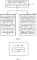
- FIG. 1 is a flowchart of an uplink full-power transmission method according to an embodiment of this disclosure. The method in FIG. 1 is applied to a terminal device and a network device, and may include the following steps.
- the terminal device performs uplink transmission based on an uplink transmit power obtained through scaling by a power scaling coefficient, where the power scaling coefficient is determined based on a power control factor.
- the network device receives uplink data sent by the terminal device, where the uplink data is transmitted on uplink by the terminal device based on the uplink transmit power obtained through scaling by the power scaling coefficient.
- the power control factor includes at least one of the following: an uplink full-power transmission capability of the terminal device, a supported transmission precoding matrix indicator TPMI reported by the terminal device, a TPMI delivered by a network device, a working mode reported by the terminal device, and the number of antenna ports for each SRS resource in a sounding reference signal SRS resource set that is configured by the network device based on the working mode.
- the uplink full-power transmission capability of the terminal device includes the following three UE capabilities:
- the full-power transmission is transmission based on a maximum transmit power of the terminal device.
- the terminal device When the terminal device supports the second UE capability or the third UE capability, the terminal device supports the following two working modes.
- Working mode 1 The number of antenna ports for each SRS resource in the SRS resource set configured by the network device is the same (that is, a configuration used for the SRS resource set for codebook-based transmission is the same as that in Rel 15); and in working mode 1, the terminal device implements full-power sending by using the TPMI delivered by the network device.
- Working mode 2 The number of antenna ports for each SRS resource in the SRS resource set configured by the network device is different (that is, a configuration used for the SRS resource set for codebook-based transmission is different from that in Rel 15); and in working mode 2, the terminal device implements full-power sending by using the number of antenna ports for an SRS resource configured by the network device.
- the uplink transmission can be performed based on the uplink transmit power obtained through scaling by the power scaling coefficient, and a plurality of power control factors (including at least one of the uplink full-power transmission capability of the terminal device, the supported transmission precoding matrix indicator TPMI reported by the terminal device, the TPMI delivered by the network device, the working mode reported by the terminal device, and the number of antenna ports for each SRS resource in the sounding reference signal SRS resource set that is configured by the network device based on the working mode) can be considered comprehensively to scale the uplink transmit power.
- a plurality of power control factors including at least one of the uplink full-power transmission capability of the terminal device, the supported transmission precoding matrix indicator TPMI reported by the terminal device, the TPMI delivered by the network device, the working mode reported by the terminal device, and the number of antenna ports for each SRS resource in the sounding reference signal SRS resource set that is configured by the network device based on the working mode
- a value of the power scaling coefficient that is determined varies with the power control factor.
- the following describes in detail how to determine the power scaling coefficient based on the power control factor.
- the power scaling coefficient for uplink transmission is ⁇
- the number of non-zero (or non-zero) uplink transmission antenna ports is ⁇ .
- the non-zero (or non-zero) uplink transmission antenna port means that row values of a precoding codebook corresponding to the antenna port are all non-zero.
- the power scaling coefficient for uplink transmission is ⁇
- the number of non-zero (or non-zero) uplink transmission antenna ports is ⁇ .
- the non-zero (or non-zero) uplink transmission antenna port means that row values of a precoding codebook corresponding to the antenna port are all non-zero, and may be referred to as the number of non-zero antenna ports hereinafter.
- a value of the power scaling coefficient ⁇ varies with the working mode supported by the UE.
- the power scaling coefficient ⁇ may be determined to be a ratio of the number of non-zero antenna ports to the maximum number of antenna ports that is supported by a single SRS resource and reported by the terminal device.
- the power scaling coefficient ⁇ may be determined to be a ratio of the number of non-zero antenna ports to the maximum number of antenna ports supported by an SRS resource that is configured by the network device.
- the power scaling coefficient for uplink transmission is ⁇
- the number of non-zero (or non-zero) uplink transmission antenna ports is ⁇ .
- the non-zero (or non-zero) uplink transmission antenna port means that row values of a precoding codebook corresponding to the antenna port are all non-zero, and may be referred to as the number of non-zero antenna ports hereinafter.
- a value of the power scaling coefficient ⁇ varies with the working mode supported by the UE.
- the power scaling coefficient ⁇ may be determined to be a ratio of the number of non-zero antenna ports to the maximum number of antenna ports that is supported by a single SRS resource and reported by the terminal device.
- a value of the power scaling coefficient may vary, depending on whether the terminal device reports a full-power transmission TPMI and whether a TPMI delivered by the network device falls within the TPMI reported by the terminal device. Specifically, there may be the following three cases:
- the TPMI reported by the terminal device is 1 2 1 0
- the TPMI delivered by the network device is 1 2 0 1
- the TPMI delivered by the network device falls within the TPMI reported by the terminal device, it can be determined in this case that ⁇ is equal to a ratio of the number fl of non-zero antenna ports to the maximum number of antenna ports that is supported by a single SRS resource and reported by the terminal device.
- the uplink full-power transmission capability of the terminal device may be determined in the following manner:
- the network device after receiving the uplink full-power transmission capability reported by the terminal device, the network device delivers the uplink full-power transmission indication to the terminal device.
- the network device may deliver the uplink full-power transmission indication to the terminal device in any one of the following manners:
- the network device may perform uplink transmission according to the steps shown in FIG. 2 .
- the method in FIG. 2 may include the following steps.
- the network device delivers a TPMI to the terminal device.
- the TPMI delivered by the network device is used to indicate that the terminal device is to perform uplink transmission based on a precoding codebook that is determined based on an uplink transmission parameter.
- the uplink transmission parameter includes the number of uplink transmission antenna ports of the terminal device, the uplink transmission rank, and the number of antenna ports for each SRS resource in the SRS resource set configured by the network device.
- the terminal device performs uplink transmission based on the precoding codebook indicated by the TPMI that is delivered by the network device and based on the uplink transmit power obtained through scaling by the power scaling coefficient.
- the precoding codebook is determined based on the number of uplink transmission antenna ports of the terminal device, the uplink transmission rank, and the number of antenna ports for each SRS resource in the SRS resource set configured by the network device.
- the terminal device performs uplink transmission based on the uplink transmit power obtained through scaling by the power scaling coefficient, but not based on the precoding codebook indicated by the TPMI that is delivered by the network device.
- the terminal device may perform uplink transmission based on the uplink transmit power obtained through scaling by the power scaling coefficient and in an SRS resource transmission mode corresponding to the number of antenna ports of an SRS resource that is the same as the uplink transmission rank.
- the terminal device when the terminal device supports the second UE capability or the third UE capability, and supports the working mode 2, if the uplink transmission rank of the terminal device is less than the number of uplink transmission antenna ports, that is, when the number of antenna ports for the SRS resource included in the SRS resource set for codebook-based transmission is less than the maximum number of antenna ports supported by the SRS resource, the precoding codebook indicated by the TPMI is useless. In this case, the terminal device does not use the precoding codebook indicated by the TPMI that is delivered by the network device.
- uplink transmission may be performed in the SRS resource transmission mode corresponding to the number of antenna ports of the SRS resource that is the same as the uplink transmission rank.
- the following describes in detail how the network device configures a precoding codebook for the terminal device based on the uplink transmission parameter.
- the terminal device supports the second UE capability or the third UE capability.
- none of the radio frequency branches of the terminal device supports full-power transmission or part of the radio frequency branches supports full-power transmission.
- the terminal device supports the working mode 1, for example, the number of antenna ports for each SRS resource in the SRS resource set configured by the network device is the same.
- the precoding codebook may alternatively vary with the number of uplink transmission antenna ports and the uplink transmission rank. Specifically:
- the terminal device supports the second UE capability or the third UE capability.
- none of the radio frequency branches of the terminal device supports full-power transmission or part of the radio frequency branches supports full-power transmission.
- the terminal device supports the working mode 2, for example, the number of antenna ports for each SRS resource in the SRS resource set configured by the network device is different.
- the precoding codebook may alternatively vary with the number of uplink transmission antenna ports, the uplink transmission rank, and the number of antenna ports for each SRS resource. Specifically:
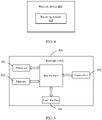
- FIG. 3 is a schematic structural diagram of a terminal device according to an embodiment of this disclosure.
- the terminal device 300 may include: a transmission module 310, configured to: perform uplink transmission based on an uplink transmit power obtained through scaling by a power scaling coefficient, where the power scaling coefficient is determined based on a power control factor.
- the power control factor includes at least one of the following: an uplink full-power transmission capability of the terminal device, a supported transmission precoding matrix indicator TPMI reported by the terminal device, a TPMI delivered by a network device, a working mode reported by the terminal device, and the number of antenna ports for each SRS resource in a sounding reference signal SRS resource set that is configured by the network device based on the working mode.
- the transmission module 310 is further configured to:
- the full-power transmission is transmission based on a maximum transmit power of the terminal device.
- the transmission module 310 is further configured to:
- the transmission module 310 is further configured to: if the power control factor satisfies the following condition, determine the power scaling coefficient to be a ratio of the number of non-zero antenna ports to the maximum number of antenna ports supported by the SRS resource that is configured by the network device:
- the transmission module 310 is further configured to:
- the transmission module 310 is further configured to:
- the transmission module 310 is further configured to: if the number of antenna ports for each SRS resource in the SRS resource set configured by the network device is different, and an uplink transmission rank is less than the number of uplink transmission antenna ports, perform uplink transmission based on the uplink transmit power in an SRS resource transmission mode corresponding to the number of antenna ports of an SRS resource that is the same as the uplink transmission rank.
- the terminal device provided in this embodiment of this disclosure is capable of implementing the processes that are implemented by the terminal device in the foregoing method embodiments. To avoid repetition, details are not described herein again.
- the terminal device can perform uplink transmission based on the uplink transmit power obtained through scaling by the power scaling coefficient, and comprehensively consider a plurality of power control factors (including at least one of the uplink full-power transmission capability of the terminal device, the supported transmission precoding matrix indicator TPMI reported by the terminal device, the TPMI delivered by the network device, the working mode reported by the terminal device, and the number of antenna ports for each SRS resource in the sounding reference signal SRS resource set that is configured by the network device based on the working mode) to scale the uplink transmit power.
- a plurality of power control factors including at least one of the uplink full-power transmission capability of the terminal device, the supported transmission precoding matrix indicator TPMI reported by the terminal device, the TPMI delivered by the network device, the working mode reported by the terminal device, and the number of antenna ports for each SRS resource in the sounding reference signal SRS resource set that is configured by the network device based on the working mode
- FIG. 4 is a schematic structural diagram of a network device according to an embodiment of this disclosure.
- the network device 400 may include: a receiving module 410, configured to receive uplink data sent by a terminal device, where the uplink data is transmitted on uplink by the terminal device based on an uplink transmit power obtained through scaling by a power scaling coefficient, and the power scaling coefficient is determined based on a power control factor.
- the power control factor includes at least one of the following: an uplink full-power transmission capability of the terminal device, a supported transmission precoding matrix indicator TPMI reported by the terminal device, a TPMI delivered by a network device, a working mode reported by the terminal device, and the number of antenna ports for each SRS resource in a sounding reference signal SRS resource set that is configured by the network device based on the working mode.
- the network device 400 further includes:
- the first delivery module 410 is further configured to:
- the first delivery module 410 is further configured to:
- the first delivery module 410 is further configured to: if the number of antenna ports for each SRS resource in the SRS resource set is the same, the number of uplink transmission antenna ports is 4, and the uplink transmission rank is 1, determine the precoding codebook to be: 1 2 1 1 1 ⁇ 1 or 1 2 1 1 1 1 ; or 1 2 0 1 0 1 ; or 1 2 1 0 1 0 ; or a fully coherent codebook, a partially coherent codebook, and a non-coherent codebook.
- the first delivery module 410 is further configured to:
- the first delivery module 410 is further configured to:
- the first delivery module 410 is further configured to: if the number of antenna ports for each SRS resource in the SRS resource set is different, the number of uplink transmission antenna ports is 4, and the SRS resource set includes two SRS resources, with one SRS resource including one antenna port and the other SRS resource including four antenna ports, then:
- the first delivery module 410 is further configured to:
- the network device 400 further includes: a second delivery module, configured to: when the uplink full-power transmission capability reported by the terminal device is received, deliver an uplink full-power transmission indication to the terminal device, where the uplink full-power transmission indication is used to indicate that the terminal device is to use an uplink full-power transmission mode for uplink transmission.
- a second delivery module configured to: when the uplink full-power transmission capability reported by the terminal device is received, deliver an uplink full-power transmission indication to the terminal device, where the uplink full-power transmission indication is used to indicate that the terminal device is to use an uplink full-power transmission mode for uplink transmission.
- the second delivery module is further configured to:
- the non-zero antenna port means that row values of a precoding codebook corresponding to the antenna port are all non-zero.
- the network device provided in this embodiment of this disclosure is capable of implementing the processes implemented by the network device in the foregoing method embodiment. To avoid repetition, details are not described herein again.
- the network device can receive the uplink data sent by the terminal device, where the uplink data is transmitted on uplink by the terminal device based on the uplink transmit power obtained through scaling by the power scaling coefficient, and the power scaling coefficient is determined based on the power control factor (including at least one of the uplink full-power transmission capability of the terminal device, the supported transmission precoding matrix indicator TPMI reported by the terminal device, the TPMI delivered by the network device, the working mode reported by the terminal device, and the number of antenna ports for each SRS resource in the sounding reference signal SRS resource set that is configured by the network device based on the working mode).
- the power control factor including at least one of the uplink full-power transmission capability of the terminal device, the supported transmission precoding matrix indicator TPMI reported by the terminal device, the TPMI delivered by the network device, the working mode reported by the terminal device, and the number of antenna ports for each SRS resource in the sounding reference signal SRS resource set that is configured by the network device based on the working mode.
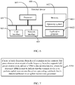
- FIG. 5 is a structural diagram of a network device to which an embodiment of this disclosure is applied. Details of the uplink full-power transmission method executed by the network device in the foregoing embodiments can be implemented, with the same effects achieved.
- the network device 500 includes a processor 501, a transceiver 502, a memory 503, a user interface 504, and a bus interface.
- the network device 500 further includes a computer program stored in the memory 503 and capable of running on the processor 501.
- the computer program is executed by the processor 501, the following step is implemented:
- a bus architecture may include any quantity of interconnected buses and bridges, specifically for interconnecting various circuits of one or more processors represented by the processor 501 and a memory represented by the memory 503.
- the bus architecture may further interconnect various other circuits such as a peripheral device, a voltage regulator, and a power management circuit. These are all well known in the art, and therefore are not further described in this specification.
- the bus interface provides an interface.
- the transceiver 502 may be a plurality of components, that is, the transceiver 502 includes a transmitter and a receiver, and provides a unit for communicating with various other apparatuses on a transmission medium.
- the user interface 504 may also be an interface that can be externally or internally connected to a required device.
- the connected device includes but is not limited to a keypad, a display, a speaker, a microphone, a joystick, and the like.
- the processor 501 is responsible for bus architecture management and general processing.
- the memory 503 may store data used when the processor 501 performs an operation.
- the following step may be further implemented: before the uplink data sent by the terminal device is received, if none of radio frequency branches of the terminal device supports full-power transmission or part of radio frequency branches supports full-power transmission, delivering a TPMI to the terminal device, where the delivered TPMI is used to indicate that the terminal device is to perform uplink transmission based on a precoding codebook that is determined based on an uplink transmission parameter; where the uplink transmission parameter includes the number of uplink transmission antenna ports of the terminal device, an uplink transmission rank, and the number of antenna ports for each SRS resource in the SRS resource set configured by the network device; and the full-power transmission indicates transmission performed based on a maximum transmit power of the terminal device.
- the following step may be further implemented:
- the following step may be further implemented:
- the following step may be further implemented:
- the following step may be further implemented:
- the following step may be further implemented: if the number of antenna ports for each SRS resource in the SRS resource set is different, the number of uplink transmission antenna ports is 4, and the SRS resource set includes two SRS resources, with one SRS resource including one antenna port and the other SRS resource including four antenna ports, then:
- the following step may be further implemented:
- the following step may be further implemented: when the uplink full-power transmission capability reported by the terminal device is received, delivering an uplink full-power transmission indication to the terminal device, where the uplink full-power transmission indication is used to indicate that the terminal device is to use an uplink full-power transmission mode for uplink transmission.
- the following step may be further implemented:
- the network device can receive the uplink data sent by the terminal device, where the uplink data is transmitted on uplink by the terminal device based on the uplink transmit power obtained through scaling by the power scaling coefficient, and the power scaling coefficient is determined based on the power control factor (including at least one of the uplink full-power transmission capability of the terminal device, the supported transmission precoding matrix indicator TPMI reported by the terminal device, the TPMI delivered by the network device, the working mode reported by the terminal device, and the number of antenna ports for each SRS resource in the sounding reference signal SRS resource set that is configured by the network device based on the working mode).
- the power control factor including at least one of the uplink full-power transmission capability of the terminal device, the supported transmission precoding matrix indicator TPMI reported by the terminal device, the TPMI delivered by the network device, the working mode reported by the terminal device, and the number of antenna ports for each SRS resource in the sounding reference signal SRS resource set that is configured by the network device based on the working mode.
- FIG. 6 is a block diagram of a terminal device according to another embodiment of this disclosure.
- the terminal device 600 shown in FIG. 6 includes at least one processor 601, a memory 602, at least one network interface 604, and a user interface 603.
- the components of the terminal device 600 are coupled together by using a bus system 605.
- the bus system 605 is configured to implement connection communication between these components.
- the bus system 605 may include not only a data bus but also a power supply bus, a control bus, and a status signal bus. However, for clarity of description, various types of buses in FIG. 6 are marked as the bus system 605.
- the user interface 603 may include a display, a keyboard, a click device (for example, a mouse or a trackball (trackball)), a touch board, or a touchscreen.
- a click device for example, a mouse or a trackball (trackball)
- a touch board for example, a touch screen, or a touchscreen.
- the memory 602 in this embodiment of this disclosure may be a volatile memory or a non-volatile memory, or may include both a volatile memory and a non-volatile memory.
- the non-volatile memory may be a read-only memory (Read-Only Memory, ROM), a programmable read only memory (Programmable ROM, PROM), an erasable programmable read-only memory (Erasable PROM, EPROM), an electrically erasable programmable read-only memory (Electrically EPROM, EEPROM), or a flash memory.
- the volatile memory may be a random access memory (Random Access Memory, RAM), which is used as an external cache.
- RAM random access memory
- SRAM static random access memory
- DRAM dynamic random access memory
- DRAM synchronous dynamic random access memory
- SDRAM double data rate synchronous dynamic random access memory
- Double DataRate SDRAM DDRSDRAM
- ESDRAM enhanced synchronous dynamic random access memory
- Synchlink DRAM SLDRAM
- Direct Rambus RAM Direct Rambus RAM
- the memory 602 stores the following elements: an executable module or a data structure, or a subset thereof, or an extended set thereof: an operating system 6021 and an application program 6022.
- An operating system 6021 includes various system programs, such as a framework layer, a kernel library layer, and a driver layer, and is configured to implement various basic services and process hardware-based tasks.
- the application program 6022 includes various application programs, such as a media player (Media Player), and a browser (Browser), and is configured to implement various application services.
- a program that implements the methods of the embodiments of this disclosure may be included in the application program 6022.
- the terminal device 600 further includes a computer program stored in the memory 609 and capable of running on the processor 601.
- the computer program implements the following steps:
- the methods disclosed in the embodiments of this disclosure are applicable to the processor 601, or implemented by the processor 601.
- the processor 601 may be an integrated circuit chip with a signal processing capability. In an implementation process, the steps in the foregoing method may be implemented by using a hardware integrated logic circuit in the processor 601, or by using instructions in a form of software.
- the processor 601 may be a general-purpose processor, a digital signal processor (Digital Signal Processor, DSP), an application-specific integrated circuit (Application Specific Integrated Circuit, ASIC), a field programmable gate array (Field Programmable Gate Array, FPGA) or another programmable logical device, a discrete gate or transistor logical device, or a discrete hardware component.
- DSP Digital Signal Processor
- ASIC Application Specific Integrated Circuit
- FPGA Field Programmable Gate Array
- the processor 601 may implement or execute the methods, steps, and logical block diagrams disclosed in the embodiments of this disclosure.
- the general-purpose processor may be a microprocessor or any regular processor.
- the steps of the methods disclosed with reference to the embodiments of this disclosure may be directly implemented by a hardware decoding processor, or may be implemented by a combination of hardware and software modules in a decoding processor.
- the software module may be located in a computer-readable storage medium that is mature in the art, such as a random access memory, a flash memory, a read-only memory, a programmable read-only memory, or an electrically erasable programmable memory, or a register.
- the computer-readable storage medium is located in the memory 602, and the processor 601 reads information in the memory 602 and implements, in combination with its hardware, the steps of the foregoing methods.
- a computer program is stored in the computer-readable storage medium, and when the computer program is executed by the processor 601, the steps of the embodiments of the foregoing method for uplink full-power transmission are implemented.
- the embodiments described in this disclosure may be implemented by hardware, software, firmware, middleware, microcode, or a combination thereof.
- the processing unit may be implemented in one or more application specific integrated circuits (Application Specific Integrated Circuit, ASIC), digital signal processors (Digital Signal processor, DSP), digital signal processing devices (DSP Device, DSPD), programmable logic devices (Programmable Logic Device, PLD), field-programmable gate arrays (Field-Programmable Gate Array, FPGA), general-purpose processors, controllers, microcontrollers, microprocessors, and other electronic units for performing the functions described in this disclosure, or a combination thereof.
- ASIC Application Specific Integrated Circuit
- DSP Digital Signal processor
- DSP Device digital signal processing devices
- PLD programmable logic devices
- FPGA field-programmable gate array
- general-purpose processors controllers, microcontrollers, microprocessors, and other electronic units for performing the functions described in this disclosure, or a combination thereof.
- the techniques described in the embodiments of this disclosure may be implemented by modules (such as processes and functions) that perform the functions described in the embodiments of this disclosure.
- Software code may be stored in the memory and executed by the processor.
- the memory may be implemented in or outside the processor.
- the following step may be further implemented: if the power control factor satisfies the following condition, determining the power scaling coefficient to be 1:
- the following step may be further implemented: if the power control factor satisfies the following condition, determining the power scaling coefficient to be a ratio of the number of non-zero antenna ports to the maximum number of antenna ports that is supported by a single SRS resource and reported by the terminal device:
- the following step may be further implemented: if the power control factor satisfies the following condition, determining the power scaling coefficient to be a ratio of the number of non-zero antenna ports to the maximum number of antenna ports supported by the SRS resource that is configured by the network device:
- the following step may be further implemented:
- the following step may be further implemented:
- the following step may be further implemented: if the number of antenna ports for each SRS resource in the SRS resource set configured by the network device is different, and an uplink transmission rank is less than the number of uplink transmission antenna ports, performing uplink transmission based on the uplink transmit power in an SRS resource transmission mode corresponding to the number of antenna ports of an SRS resource that is the same as the uplink transmission rank.
- the terminal device 600 is capable of implementing the processes implemented by the terminal device in the foregoing embodiments. To avoid repetition, details are not described herein again.
- the terminal device can perform uplink transmission based on the uplink transmit power obtained through scaling by the power scaling coefficient, and comprehensively consider a plurality of power control factors (including at least one of the uplink full-power transmission capability of the terminal device, the supported transmission precoding matrix indicator TPMI reported by the terminal device, the TPMI delivered by the network device, the working mode reported by the terminal device, and the number of antenna ports for each SRS resource in the sounding reference signal SRS resource set that is configured by the network device based on the working mode) to scale the uplink transmit power.
- a plurality of power control factors including at least one of the uplink full-power transmission capability of the terminal device, the supported transmission precoding matrix indicator TPMI reported by the terminal device, the TPMI delivered by the network device, the working mode reported by the terminal device, and the number of antenna ports for each SRS resource in the sounding reference signal SRS resource set that is configured by the network device based on the working mode
- an embodiment of this disclosure further provides a terminal device, including a processor, a memory, and a computer program stored in the memory and capable of running on the processor.
- a terminal device including a processor, a memory, and a computer program stored in the memory and capable of running on the processor.
- the computer program is executed by the processor, the processes of the foregoing embodiment of the uplink full-power transmission method are implemented, with the same technical effects achieved. To avoid repetition, details are not described herein again.
- an embodiment of this disclosure further provides a network device, including a processor, a memory, and a computer program stored in the memory and capable of running on the processor.
- a network device including a processor, a memory, and a computer program stored in the memory and capable of running on the processor.
- the computer program is executed by the processor, the processes of the foregoing embodiment of the uplink full-power transmission method are implemented, with the same technical effects achieved. To avoid repetition, details are not described herein again.
- An embodiment of this disclosure further provides a computer-readable storage medium, where a computer program is stored in the computer readable storage medium.
- a computer program is stored in the computer readable storage medium.
- the computer-readable storage medium is, for example, a read-only memory (Read-Only Memory, ROM for short), a random access memory (Random Access Memory, RAM for short), a magnetic disk, or an optical disc.
- FIG. 7 is a flowchart of an uplink full-power transmission method according to an embodiment of this disclosure. The method in FIG. 7 is applied to a network device, and may include:
- the uplink transmission parameter includes the number of uplink transmission antenna ports of the terminal device, an uplink transmission rank, and the number of antenna ports for each SRS resource in the SRS resource set configured by the network device; and the full-power transmission indicates transmission performed based on a maximum transmit power of the terminal device.
- precoding codebook may alternatively vary with the number of uplink transmission antenna ports and the uplink transmission rank.
- a manner of determining a precoding codebook is the same as that described in the foregoing embodiment, and is not repeated herein.
- the software product is stored in a storage medium (such as a ROM/RAM, a magnetic disk, or an optical disc), and includes several instructions for instructing a terminal (which may be a mobile phone, a computer, a server, an air conditioner, a network device, or the like) to perform the methods described in the embodiments of this disclosure.
- a storage medium such as a ROM/RAM, a magnetic disk, or an optical disc
- a terminal which may be a mobile phone, a computer, a server, an air conditioner, a network device, or the like
Landscapes
- Engineering & Computer Science (AREA)
- Signal Processing (AREA)
- Computer Networks & Wireless Communication (AREA)
- Mobile Radio Communication Systems (AREA)
- Bidirectional Digital Transmission (AREA)
- Transmitters (AREA)
Abstract
Description
- This application claims priority to
Chinese Patent Application No. 201910727566.7, filed with the China National Intellectual Property Administration on August 7, 2019 - This disclosure relates to the field of wireless communications technologies, and in particular, to an uplink full-power transmission method and a device.
- In NR (New Radio, new radio) Rel 15, a physical uplink shared channel (Physical Uplink Shared Channel, PUSCH) supports codebook-based transmission and non-codebook-based transmission, imposing higher requirements for implementation of PUSCH power control. Codebook-based transmission means that a user terminal (User Equipment, UE) selects a precoding codebook according to an indication of a network side; non-codebook-based transmission means that the UE may dynamically determine a precoding codebook based on channel state information (Channel State Information, CSI).
- For codebook-based PUSCH transmission, when the number of sounding reference signal (Sounding Reference Signal, SRS) antenna ports configured for codebook-based transmission by the network side is greater than 1, a PUSCH power may be scaled based on a ratio of the number of non-zero PUSCH antenna ports to the maximum number of SRS antenna ports supported by a single SRS resource of the UE, and then is divided equally among the non-zero PUSCH antenna ports. For non-codebook-based PUSCH transmission, or for codebook-based PUSCH transmission in which the number of SRS antenna ports used for codebook-based transmission is equal to 1, a PUSCH power may be divided equally among non-zero PUSCH antenna ports.
- The foregoing PUSCH power scaling behavior for codebook-based transmission may cause uplink non-full-power sending. For example, when the network side configures that the UE uses partial transmission precoding matrix indicator (Transmission Precoding Matrix Indicator, TPMI) for transmission (such as

- Embodiments of this disclosure provide an uplink full-power transmission method and a device, so as to resolve the problem that uplink full-power transmission cannot be ensured for UE in the related art.
- In order to resolve the foregoing technical problem, the embodiments of this disclosure are implemented as follows:
- According to a first aspect, an embodiment of this disclosure provides an uplink full-power transmission method. The method is applied to a terminal device and includes: performing uplink transmission based on an uplink transmit power obtained through scaling by a power scaling coefficient, where the power scaling coefficient is determined based on a power control factor, and the power control factor includes at least one of the following: an uplink full-power transmission capability of the terminal device, a supported transmission precoding matrix indicator TPMI reported by the terminal device, a TPMI delivered by a network device, a working mode reported by the terminal device, and the number of antenna ports for each SRS resource in a sounding reference signal SRS resource set that is configured by the network device based on the working mode.
- According to a second aspect, an embodiment of this disclosure further provides an uplink full-power transmission method. The method is applied to a network device and includes: receiving uplink data sent by a terminal device, where the uplink data is transmitted on uplink by the terminal device based on an uplink transmit power obtained through scaling by a power scaling coefficient, the power scaling coefficient is determined based on a power control factor, and the power control factor includes at least one of the following: an uplink full-power transmission capability of the terminal device, a supported transmission precoding matrix indicator TPMI reported by the terminal device, a TPMI delivered by the network device, a working mode reported by the terminal device, and the number of antenna ports for each SRS resource in a sounding reference signal SRS resource set that is configured by the network device based on the working mode.
- According to a third aspect, an embodiment of this disclosure further provides a terminal device. The terminal device includes: a transmission module, configured to: perform uplink transmission based on an uplink transmit power obtained through scaling by a power scaling coefficient, where the power scaling coefficient is determined based on a power control factor, and the power control factor includes at least one of the following: an uplink full-power transmission capability of the terminal device, a supported transmission precoding matrix indicator TPMI reported by the terminal device, a TPMI delivered by a network device, a working mode reported by the terminal device, and the number of antenna ports for each SRS resource in a sounding reference signal SRS resource set that is configured by the network device based on the working mode.
- According to a fourth aspect, an embodiment of this disclosure further provides a network device. The network device includes: a receiving module, configured to receive uplink data sent by a terminal device, where the uplink data is transmitted on uplink by the terminal device based on an uplink transmit power obtained through scaling by a power scaling coefficient, the power scaling coefficient is determined based on a power control factor, and the power control factor includes at least one of the following: an uplink full-power transmission capability of the terminal device, a supported transmission precoding matrix indicator TPMI reported by the terminal device, a TPMI delivered by the network device, a working mode reported by the terminal device, and the number of antenna ports for each SRS resource in a sounding reference signal SRS resource set that is configured by the network device based on the working mode.
- According to a fifth aspect, an embodiment of this disclosure further provides a terminal device, including a memory, storing a computer program instruction; and a processor, where when the computer program instruction is executed by the processor, the uplink full-power transmission method according to the first aspect is implemented.
- According to a sixth aspect, an embodiment of this disclosure further provides a network device, including a memory, storing a computer program instruction; and a processor, where when the computer program instruction is executed by the processor, the uplink full-power transmission method according to the second aspect is implemented.
- According to a seventh aspect, an embodiment of this disclosure further provides a computer-readable storage medium, where the computer-readable storage medium includes an instruction, and when the instruction is run on a computer, the computer executes the uplink full-power transmission method according to the first aspect or the second aspect.
- According to the embodiments of this disclosure, the uplink transmission can be performed based on the uplink transmit power obtained through scaling by the power scaling coefficient, and a plurality of power control factors (including at least one of the uplink full-power transmission capability of the terminal device, the supported transmission precoding matrix indicator TPMI reported by the terminal device, the TPMI delivered by the network device, the working mode reported by the terminal device, and the number of antenna ports for each SRS resource in the sounding reference signal SRS resource set that is configured by the network device based on the working mode) can be considered comprehensively to scale the uplink transmit power. In this way, an uplink transmit power is improved, an uplink coverage is enhanced, and uplink full-power transmission is implemented for the terminal device.
- To describe the technical solutions in the embodiments of this disclosure or in the related art more clearly, the following briefly describes the accompanying drawings required for describing the embodiments or the related art. Apparently, the accompanying drawings in the following description show merely some embodiments recorded in this disclosure, and a person of ordinary skill in the art may still derive other drawings from these accompanying drawings without creative efforts.
-
FIG. 1 is a schematic flowchart of an uplink full-power transmission method according to an embodiment of this disclosure; -
FIG. 2 is a schematic flowchart of an uplink full-power transmission method according to another embodiment of this disclosure; -
FIG. 3 is a schematic structural diagram of a terminal device according to an embodiment of this disclosure; -
FIG. 4 is a schematic structural diagram of a network device according to an embodiment of this disclosure; -
FIG. 5 is a schematic structural diagram of a network device according to another embodiment of this disclosure; -
FIG. 6 is a schematic structural diagram of a terminal device according to another embodiment of this disclosure; and -
FIG. 7 is a schematic flowchart of an uplink full-power transmission method according to another embodiment of this disclosure. - The following clearly and completely describes the technical solutions in the embodiments of this disclosure with reference to the accompanying drawings in the embodiments of this disclosure. Apparently, the described embodiments are some but not all of the embodiments of this disclosure. All other embodiments obtained by a person of ordinary skill in the art based on the embodiments of this disclosure without creative efforts shall fall within the protection scope of this disclosure.
- The technical solutions in the embodiments of this disclosure may be applied to various communications systems, such as a global system for mobile communications (Global System of Mobile communication, GSM), a code division multiple access (Code Division Multiple Access, CDMA) system, a wideband code division multiple access (Wideband Code Division Multiple Access, WCDMA) system, a general packet radio service (General Packet Radio Service, GPRS) system, a long term evolution (Long Term Evolution, LTE) system, or a new radio (New Radio, NR) system.
- A user terminal (User Equipment, UE) may also be referred to as a mobile terminal (Mobile Terminal), an access terminal, a subscriber unit, a subscriber station, a mobile station, a mobile console, a remote station, a remote terminal, a mobile device, a user terminal, a terminal, a wireless communications device, a user agent, a user apparatus, or the like. The access terminal may be a cellular phone, a cordless phone, a Session Initiation Protocol (Session Initiation Protocol, SIP) phone, a wireless local loop (Wireless Local Loop, WLL) station, a personal digital assistant (Personal Digital Assistant, PDA), a handheld device having a wireless communication function, a computing device, another processing device connected to a wireless modem, an in-vehicle device, a wearable device, a terminal device in a future 5G network, a terminal device in a future evolved public land mobile network (Public Land Mobile Network, PLMN), or the like.
- A network device may be a device used for communicating with a mobile device. The network device may be a base station (Base Transceiver Station, BTS) in global system for mobile communications (Global System of Mobile communication, GSM) or CDMA, or may be a base station (NodeB, NB) in WCDMA, or may be an eNB or evolved base station (Evolved Node B, eNodeB), an access point, an in-vehicle device, or a wearable device in LTE, or a network-side device in a future 5G network, or a network device in a future evolved PLMN network.
-
FIG. 1 is a flowchart of an uplink full-power transmission method according to an embodiment of this disclosure. The method inFIG. 1 is applied to a terminal device and a network device, and may include the following steps. - S101: The terminal device performs uplink transmission based on an uplink transmit power obtained through scaling by a power scaling coefficient, where the power scaling coefficient is determined based on a power control factor.
- S 102: The network device receives uplink data sent by the terminal device, where the uplink data is transmitted on uplink by the terminal device based on the uplink transmit power obtained through scaling by the power scaling coefficient.
- In this embodiment, the power control factor includes at least one of the following: an uplink full-power transmission capability of the terminal device, a supported transmission precoding matrix indicator TPMI reported by the terminal device, a TPMI delivered by a network device, a working mode reported by the terminal device, and the number of antenna ports for each SRS resource in a sounding reference signal SRS resource set that is configured by the network device based on the working mode.
- The uplink full-power transmission capability of the terminal device includes the following three UE capabilities:
- first UE capability: all radio frequency branches of the terminal device support full-power transmission;
- second UE capability: none of radio frequency branches of the terminal device supports full-power transmission; and
- third UE capability: part of radio frequency branches of the terminal device supports full-power transmission.
- The full-power transmission is transmission based on a maximum transmit power of the terminal device.
- When the terminal device supports the second UE capability or the third UE capability, the terminal device supports the following two working modes.
- Working mode 1: The number of antenna ports for each SRS resource in the SRS resource set configured by the network device is the same (that is, a configuration used for the SRS resource set for codebook-based transmission is the same as that in Rel 15); and in working mode 1, the terminal device implements full-power sending by using the TPMI delivered by the network device.
- Working mode 2: The number of antenna ports for each SRS resource in the SRS resource set configured by the network device is different (that is, a configuration used for the SRS resource set for codebook-based transmission is different from that in Rel 15); and in working mode 2, the terminal device implements full-power sending by using the number of antenna ports for an SRS resource configured by the network device.
- According to this embodiment of this disclosure, the uplink transmission can be performed based on the uplink transmit power obtained through scaling by the power scaling coefficient, and a plurality of power control factors (including at least one of the uplink full-power transmission capability of the terminal device, the supported transmission precoding matrix indicator TPMI reported by the terminal device, the TPMI delivered by the network device, the working mode reported by the terminal device, and the number of antenna ports for each SRS resource in the sounding reference signal SRS resource set that is configured by the network device based on the working mode) can be considered comprehensively to scale the uplink transmit power. In this way, an uplink transmit power is improved, an uplink coverage is enhanced, and uplink full-power transmission is implemented for the terminal device.
- In the foregoing embodiment, a value of the power scaling coefficient that is determined varies with the power control factor. The following describes in detail how to determine the power scaling coefficient based on the power control factor.
- Assuming that a before-scaling uplink power calculated through uplink power control is P, the power scaling coefficient for uplink transmission is α, and the number of non-zero (or non-zero) uplink transmission antenna ports is β. The non-zero (or non-zero) uplink transmission antenna port means that row values of a precoding codebook corresponding to the antenna port are all non-zero.
- When the terminal device supports the first UE capability (for example, all the radio frequency branches of the terminal device support full-power transmission), the power scaling coefficient may be determined to be 1, that is, α=1.
- After determining the power scaling coefficient α=1, the terminal device first scales the uplink power P based on the power scaling coefficient α, and then performs equal division among the non-zero uplink transmission antenna ports to obtain an uplink transmit power (actual transmit power) P' of each uplink transmission antenna port:

- Assuming that a before-scaling uplink power calculated through uplink power control is P, the power scaling coefficient for uplink transmission is α, and the number of non-zero (or non-zero) uplink transmission antenna ports is β. The non-zero (or non-zero) uplink transmission antenna port means that row values of a precoding codebook corresponding to the antenna port are all non-zero, and may be referred to as the number of non-zero antenna ports hereinafter.
- When the terminal device supports the second UE capability (for example, none of the radio frequency branches of the terminal device supports full-power transmission), a value of the power scaling coefficient α varies with the working mode supported by the UE.
- Specifically, when the UE supports the working mode 1 (for example, the terminal device reports the working mode 1, and the number of antenna ports for each SRS resource in the SRS resource set that is configured by the network device based on the working mode reported by the terminal device is the same), the power scaling coefficient α may be determined to be a ratio of the number of non-zero antenna ports to the maximum number of antenna ports that is supported by a single SRS resource and reported by the terminal device.
- When the UE supports the working mode 2 (for example, the terminal device reports the working mode 2, and the number of antenna ports for each SRS resource in the SRS resource set that is configured by the network device based on the working mode reported by the terminal device is different), the power scaling coefficient α may be determined to be a ratio of the number of non-zero antenna ports to the maximum number of antenna ports supported by an SRS resource that is configured by the network device.
- After determining the power scaling coefficient α by using the method of this embodiment, the terminal device first scales the uplink power P based on the power scaling coefficient α, and then performs equal division among the non-zero uplink transmission antenna ports to obtain an uplink transmit power (actual transmit power) P' of each uplink transmission antenna port:

- Assuming that a before-scaling uplink power calculated through uplink power control is P, the power scaling coefficient for uplink transmission is α, and the number of non-zero (or non-zero) uplink transmission antenna ports is β. The non-zero (or non-zero) uplink transmission antenna port means that row values of a precoding codebook corresponding to the antenna port are all non-zero, and may be referred to as the number of non-zero antenna ports hereinafter.
- When the terminal device supports the third UE capability (for example, part of the radio frequency branches of the terminal device supports full-power transmission), a value of the power scaling coefficient α varies with the working mode supported by the UE.
- Specifically, when the UE supports the working mode 1 (for example, the terminal device reports the working mode 1, and the number of antenna ports for each SRS resource in the SRS resource set that is configured by the network device based on the working mode reported by the terminal device is the same), the power scaling coefficient α may be determined to be a ratio of the number of non-zero antenna ports to the maximum number of antenna ports that is supported by a single SRS resource and reported by the terminal device.
- When the UE supports working mode 2 (for example, the terminal device reports the working mode 2, and the number of antenna ports for each SRS resource in the SRS resource set that is configured by the network device based on the working mode reported by the terminal device is different), a value of the power scaling coefficient may vary, depending on whether the terminal device reports a full-power transmission TPMI and whether a TPMI delivered by the network device falls within the TPMI reported by the terminal device. Specifically, there may be the following three cases:
- a. if the terminal device reports no full-power transmission TPMI, the power scaling coefficient α may be determined to be a ratio of the number of non-zero antenna ports to the maximum number of antenna ports that is supported by the SRS resource and configured by the network device;
- b. if the terminal device reports a full-power transmission TPMI, and the TPMI delivered by the network device falls within the TPMI reported by the terminal device, the power scaling coefficient may be determined to be 1, that is, α=1; where
for example, the TPMI reported by the terminal device is

- c. if the terminal device reports the full-power transmission TPMI, and the TPMI delivered by the network device does not fall within the TPMI reported by the terminal device, the power scaling coefficient α may be determined to be a ratio of the number of non-zero antenna ports to the maximum number of antenna ports that is supported by a single SRS resource and reported by the terminal device.
- For example, the TPMI reported by the terminal device is


- After determining the power scaling coefficient α by using the method of this embodiment, the terminal device first scales the uplink power P based on the power scaling coefficient α, and then performs equal division among the non-zero uplink transmission antenna ports to obtain an uplink transmit power (actual transmit power) P' of each uplink transmission antenna port:

- In any one of the foregoing embodiments, the uplink full-power transmission capability of the terminal device may be determined in the following manner:
- (1) the terminal device reports the uplink full-power transmission capability; or
- (2) the terminal device reports the uplink full-power transmission capability and receives an uplink full-power transmission indication delivered by the network device, where the uplink full-power transmission indication is used to indicate that the terminal device is to use an uplink full-power transmission mode for uplink transmission.
- In the manner (2), after receiving the uplink full-power transmission capability reported by the terminal device, the network device delivers the uplink full-power transmission indication to the terminal device. The network device may deliver the uplink full-power transmission indication to the terminal device in any one of the following manners:
- manner 1: delivering the uplink full-power transmission indication through radio resource control RRC, medium access control MAC, or downlink control information DCI;
- manner 2: delivering a full-power transmission TPMI, and using the TPMI to indicate that the terminal device is to use an uplink full-power transmission mode for uplink transmission; and
- manner 3: configuring, for the terminal device, an SRS resource corresponding to the precoding codebook, where the number of antenna ports of the configured SRS resource is the same as the number of non-zero antenna ports indicated by the precoding codebook.
- After the terminal device reports the uplink full-power transmission capability, the network device may perform uplink transmission according to the steps shown in
FIG. 2 . The method inFIG. 2 may include the following steps. - S201: When the uplink full-power transmission capability reported by the terminal device is the second UE capability or the third UE capability, the network device delivers a TPMI to the terminal device.
- The TPMI delivered by the network device is used to indicate that the terminal device is to perform uplink transmission based on a precoding codebook that is determined based on an uplink transmission parameter. The uplink transmission parameter includes the number of uplink transmission antenna ports of the terminal device, the uplink transmission rank, and the number of antenna ports for each SRS resource in the SRS resource set configured by the network device.
- S202: If the uplink transmission rank of the terminal device is equal to the number of uplink transmission antenna ports of the terminal device, the terminal device performs uplink transmission based on the precoding codebook indicated by the TPMI that is delivered by the network device and based on the uplink transmit power obtained through scaling by the power scaling coefficient.
- The precoding codebook is determined based on the number of uplink transmission antenna ports of the terminal device, the uplink transmission rank, and the number of antenna ports for each SRS resource in the SRS resource set configured by the network device.
- S203: If the number of antenna ports for each SRS resource in the SRS resource set is different, and the uplink transmission rank of the terminal device is less than the number of uplink transmission antenna ports, the terminal device performs uplink transmission based on the uplink transmit power obtained through scaling by the power scaling coefficient, but not based on the precoding codebook indicated by the TPMI that is delivered by the network device.
- Optionally, if the number of antenna ports for each SRS resource in the SRS resource set is different, and the uplink transmission rank of the terminal device is less than the number of uplink transmission antenna ports, the terminal device may perform uplink transmission based on the uplink transmit power obtained through scaling by the power scaling coefficient and in an SRS resource transmission mode corresponding to the number of antenna ports of an SRS resource that is the same as the uplink transmission rank.
- It can be learned that, in this embodiment, when the terminal device supports the second UE capability or the third UE capability, and supports the working mode 2, if the uplink transmission rank of the terminal device is less than the number of uplink transmission antenna ports, that is, when the number of antenna ports for the SRS resource included in the SRS resource set for codebook-based transmission is less than the maximum number of antenna ports supported by the SRS resource, the precoding codebook indicated by the TPMI is useless. In this case, the terminal device does not use the precoding codebook indicated by the TPMI that is delivered by the network device. Optionally, uplink transmission may be performed in the SRS resource transmission mode corresponding to the number of antenna ports of the SRS resource that is the same as the uplink transmission rank.
- The following describes in detail how the network device configures a precoding codebook for the terminal device based on the uplink transmission parameter.
- In this embodiment, the terminal device supports the second UE capability or the third UE capability. For example, none of the radio frequency branches of the terminal device supports full-power transmission or part of the radio frequency branches supports full-power transmission. The terminal device supports the working mode 1, for example, the number of antenna ports for each SRS resource in the SRS resource set configured by the network device is the same. Based on this, the precoding codebook may alternatively vary with the number of uplink transmission antenna ports and the uplink transmission rank. Specifically:
- (1) When the number of uplink transmission antenna ports is 2 and the uplink transmission rank is 1, the precoding codebook may be determined to be:
- a codebook corresponding to TPMI=2, namely,

- a fully coherent codebook, a partially coherent codebook, and a non-coherent codebook.
- a codebook corresponding to TPMI=2, namely,
- (2) When the number of uplink transmission antenna ports is 4, the precoding codebook may be divided into the following cases, depending on different uplink transmission ranks:
- a. When the uplink transmission rank is 1, the precoding codebook may be determined to be:
- a codebook corresponding to TPMI=12, namely,


- a codebook corresponding to TPMI=8, namely,

- a codebook corresponding to TPMI=4, namely,

- a fully coherent codebook, a partially coherent codebook, and a non-coherent codebook.


- a codebook corresponding to TPMI=12, namely,
- b. When the uplink transmission rank is 2, the precoding codebook may be determined to be:
- a codebook corresponding to TPMI=6, namely,

- a fully coherent codebook, a partially coherent codebook, and a non-coherent codebook.
- a codebook corresponding to TPMI=6, namely,
- c. When the uplink transmission rank is 3, the precoding codebook may be determined to be:
- a codebook corresponding to TPMI=1, namely,

- a fully coherent codebook, a partially coherent codebook, and a non-coherent codebook.
- a codebook corresponding to TPMI=1, namely,
- a. When the uplink transmission rank is 1, the precoding codebook may be determined to be:
- In this embodiment, the terminal device supports the second UE capability or the third UE capability. For example, none of the radio frequency branches of the terminal device supports full-power transmission or part of the radio frequency branches supports full-power transmission. The terminal device supports the working mode 2, for example, the number of antenna ports for each SRS resource in the SRS resource set configured by the network device is different. Based on this, the precoding codebook may alternatively vary with the number of uplink transmission antenna ports, the uplink transmission rank, and the number of antenna ports for each SRS resource. Specifically:
- (1) The number of uplink transmission antenna ports is 2, and the SRS resource configured by the network device includes two SRS resources, with one SRS resource including one antenna port and the other SRS resource including two antenna ports. In this case, if the network device configures an antenna port for only one SRS resource, because the uplink transmission rank of the terminal device is less than the number of uplink transmission antenna ports, that is, the number of antenna ports for each SRS resource in the SRS resource set is less than the maximum number of antenna ports supported by the SRS resource, the precoding codebook indicated by the TPMI is useless. In this case, the terminal device does not use the precoding codebook indicated by the TPMI that is delivered by the network device. Optionally, uplink transmission may be performed in the SRS resource transmission mode corresponding to the number of antenna ports of the SRS resource that is the same as the uplink transmission rank.
- (2) The number of uplink transmission antenna ports is 4. The precoding codebook alternatively varies with the number of SRS resources included in the SRS resource set and the number of antenna ports included in each SRS resource. Specifically:
- a. The SRS resource set includes two SRS resources, with one SRS resource including one antenna port and the other SRS resource including four antenna ports, then:
- when the uplink transmission rank is 1, because the uplink transmission rank is less than the uplink transmission antenna port number, that is, the number of antenna ports for each SRS resource in the SRS resource set is less than the maximum number of antenna ports supported by the SRS resource, the precoding codebook indicated by the TPMI is useless; in this case, the terminal device does not use the precoding codebook indicated by the TPMI that is delivered by the network device; optionally, uplink transmission may be performed in the SRS resource transmission mode corresponding to the number of antenna ports of the SRS resource that is the same as the uplink transmission rank;
- when the uplink transmission rank is 2, the precoding codebook may be determined to be: a codebook corresponding to TPMI=6, that is:

- when the uplink transmission rank is 3, the precoding codebook may be determined to be: a codebook corresponding to TPMI=1, that is:

- b. The SRS resource set includes three SRS resources, with one SRS resource including one antenna port, a second SRS resource including two antenna ports, and a third SRS resource including four antenna ports, then:
- when the uplink transmission rank is 1 or 2, because the uplink transmission rank is less than the uplink transmission antenna port number, that is, the number of antenna ports for each SRS resource in the SRS resource set is less than the maximum number of antenna ports supported by the SRS resource, the precoding codebook indicated by the TPMI is useless; in this case, the terminal device does not use the precoding codebook indicated by the TPMI that is delivered by the network device; optionally, uplink transmission may be performed in the SRS resource transmission mode corresponding to the number of antenna ports of the SRS resource that is the same as the uplink transmission rank; or
- when the uplink transmission rank is 3, the precoding codebook may be determined to be: a codebook corresponding to TPMI=1, that is:

- a. The SRS resource set includes two SRS resources, with one SRS resource including one antenna port and the other SRS resource including four antenna ports, then:
- The specific embodiments of this specification are described above. Other embodiments fall within the scope of the claims. In some cases, actions or steps described in the claims may be performed in an order different from that in the embodiments, and may still implement desired results. In addition, the processes described in the accompanying drawings are not necessarily performed in an illustrated particular order or sequentially to implement the desired results. In some embodiments, multi-task processing and parallel processing are also acceptable or may be advantageous.
-
FIG. 3 is a schematic structural diagram of a terminal device according to an embodiment of this disclosure. Referring toFIG. 3 , theterminal device 300 may include:
atransmission module 310, configured to: perform uplink transmission based on an uplink transmit power obtained through scaling by a power scaling coefficient, where the power scaling coefficient is determined based on a power control factor. - The power control factor includes at least one of the following: an uplink full-power transmission capability of the terminal device, a supported transmission precoding matrix indicator TPMI reported by the terminal device, a TPMI delivered by a network device, a working mode reported by the terminal device, and the number of antenna ports for each SRS resource in a sounding reference signal SRS resource set that is configured by the network device based on the working mode.
- In an embodiment, the
transmission module 310 is further configured to: - if the power control factor satisfies the following condition, determine the power scaling coefficient to be 1:
- all radio frequency branches of the terminal device support full-power transmission; or
- part of radio frequency branches of the terminal device supports full-power transmission, the number of antenna ports for each SRS resource in the SRS resource set is different, and the TPMI delivered by the network device falls within the TPMI reported by the terminal device.
- The full-power transmission is transmission based on a maximum transmit power of the terminal device.
- In an embodiment, the
transmission module 310 is further configured to: - if the power control factor satisfies the following condition, determine the power scaling coefficient to be a ratio of the number of non-zero antenna ports to the maximum number of antenna ports that is supported by a single SRS resource and reported by the terminal device:
- none of radio frequency branches of the terminal device supports full-power transmission, and the number of antenna ports for each SRS resource in the SRS resource set is the same; or
- part of radio frequency branches of the terminal device supports full-power transmission, and the number of antenna ports for each SRS resource in the SRS resource set is the same; or
- part of radio frequency branches of the terminal device supports full-power transmission, the number of antenna ports for each SRS resource in the SRS resource set is different, and the TPMI delivered by the network device does not fall within the TPMI reported by the terminal device; where
- the non-zero antenna port means that row values of a precoding codebook corresponding to the antenna port are all non-zero.
- In an embodiment, the
transmission module 310 is further configured to:
if the power control factor satisfies the following condition, determine the power scaling coefficient to be a ratio of the number of non-zero antenna ports to the maximum number of antenna ports supported by the SRS resource that is configured by the network device: - none of radio frequency branches of the terminal device supports full-power sending, and the number of antenna ports for each SRS resource in the SRS resource set is different; or
- part of radio frequency branches of the terminal device supports full-power sending, the number of antenna ports for each SRS resource in the SRS resource set is different, and no full-power transmission TPMI is reported by the terminal device.
- In an embodiment, the
transmission module 310 is further configured to: - report the uplink full-power transmission capability; or
- report the uplink full-power transmission capability and receive an uplink full-power transmission indication delivered by the network device, where the uplink full-power transmission indication is used to indicate that the terminal device is to use an uplink full-power transmission mode for uplink transmission.
- In an embodiment, the
transmission module 310 is further configured to: - if the uplink full-power transmission capability of the terminal device is that none of radio frequency branches supports full-power transmission or part of radio frequency branches supports full-power transmission, and an uplink transmission rank of the terminal device is equal to the number of uplink transmission antenna ports of the terminal device, perform uplink transmission based on the uplink transmit power according to a precoding codebook delivered by the network device; where
- the precoding codebook is determined based on the number of uplink transmission antenna ports of the terminal device, the uplink transmission rank, and the number of antenna ports for each SRS resource in the SRS resource set.
- In an embodiment, the
transmission module 310 is further configured to:
if the number of antenna ports for each SRS resource in the SRS resource set configured by the network device is different, and an uplink transmission rank is less than the number of uplink transmission antenna ports, perform uplink transmission based on the uplink transmit power in an SRS resource transmission mode corresponding to the number of antenna ports of an SRS resource that is the same as the uplink transmission rank. - The terminal device provided in this embodiment of this disclosure is capable of implementing the processes that are implemented by the terminal device in the foregoing method embodiments. To avoid repetition, details are not described herein again.
- According to this embodiment of this disclosure, the terminal device can perform uplink transmission based on the uplink transmit power obtained through scaling by the power scaling coefficient, and comprehensively consider a plurality of power control factors (including at least one of the uplink full-power transmission capability of the terminal device, the supported transmission precoding matrix indicator TPMI reported by the terminal device, the TPMI delivered by the network device, the working mode reported by the terminal device, and the number of antenna ports for each SRS resource in the sounding reference signal SRS resource set that is configured by the network device based on the working mode) to scale the uplink transmit power. In this way, an uplink transmit power is improved, an uplink coverage is enhanced, and uplink full-power transmission is implemented for the terminal device.
-
FIG. 4 is a schematic structural diagram of a network device according to an embodiment of this disclosure. Referring toFIG. 4 , thenetwork device 400 may include:
areceiving module 410, configured to receive uplink data sent by a terminal device, where the uplink data is transmitted on uplink by the terminal device based on an uplink transmit power obtained through scaling by a power scaling coefficient, and the power scaling coefficient is determined based on a power control factor. - The power control factor includes at least one of the following: an uplink full-power transmission capability of the terminal device, a supported transmission precoding matrix indicator TPMI reported by the terminal device, a TPMI delivered by a network device, a working mode reported by the terminal device, and the number of antenna ports for each SRS resource in a sounding reference signal SRS resource set that is configured by the network device based on the working mode.
- In an embodiment, the
network device 400 further includes: - a first delivery module, configured to: before the uplink data sent by the terminal device is received, if none of radio frequency branches of the terminal device supports full-power transmission or part of radio frequency branches supports full-power transmission, deliver a TPMI to the terminal device, where the delivered TPMI is used to indicate that the terminal device is to perform uplink transmission based on a precoding codebook that is determined based on an uplink transmission parameter; where
- the uplink transmission parameter includes the number of uplink transmission antenna ports of the terminal device, an uplink transmission rank, and the number of antenna ports for each SRS resource in the SRS resource set configured by the network device; and the full-power transmission indicates transmission performed based on a maximum transmit power of the terminal device.
- In an embodiment, the
first delivery module 410 is further configured to: - if the number of antenna ports for each SRS resource in the SRS resource set is the same, the number of uplink transmission antenna ports is 2, and the uplink transmission rank is 1, determine the precoding codebook to be:

- a fully coherent codebook, a partially coherent codebook, and a non-coherent codebook.
- In an embodiment, the
first delivery module 410 is further configured to: - if the number of antenna ports for each SRS resource in the SRS resource set is the same, the number of uplink transmission antenna ports is 2, and the uplink transmission rank is 1, determine the precoding codebook to be:

- a fully coherent codebook, a partially coherent codebook, and a non-coherent codebook.
- In an embodiment, the
first delivery module 410 is further configured to: if the number of antenna ports for each SRS resource in the SRS resource set is the same, the number of uplink transmission antenna ports is 4, and the uplink transmission rank is 1, determine the precoding codebook to be:


- In an embodiment, the
first delivery module 410 is further configured to: - if the number of antenna ports for each SRS resource in the SRS resource set is the same, the number of uplink transmission antenna ports is 4, and the uplink transmission rank is 2, determine the precoding codebook to be:

- a fully coherent codebook, a partially coherent codebook, and a non-coherent codebook.
- In an embodiment, the
first delivery module 410 is further configured to: - if the number of antenna ports for each SRS resource in the SRS resource set is the same, the number of uplink transmission antenna ports is 4, and the uplink transmission rank is 3, determine the precoding codebook to be:

- a fully coherent codebook, a partially coherent codebook, and a non-coherent codebook.
- In an embodiment, the
first delivery module 410 is further configured to:
if the number of antenna ports for each SRS resource in the SRS resource set is different, the number of uplink transmission antenna ports is 4, and the SRS resource set includes two SRS resources, with one SRS resource including one antenna port and the other SRS resource including four antenna ports, then: - if the uplink transmission rank is 2, determine the precoding codebook to be:

- if the uplink transmission rank is 3, determine the precoding codebook to be:

- In an embodiment, the
first delivery module 410 is further configured to: - if the number of antenna ports for each SRS resource in the SRS resource set is different, the number of uplink transmission antenna ports is 4, the uplink transmission rank is 3, and the SRS resource set includes three SRS resources, with one SRS resource including one antenna port, a second SRS resource including two antenna ports, and a third SRS resource including four antenna ports, determine the precoding codebook to be:

- a fully coherent codebook, a partially coherent codebook, and a non-coherent codebook.
- In an embodiment, the
network device 400 further includes:
a second delivery module, configured to: when the uplink full-power transmission capability reported by the terminal device is received, deliver an uplink full-power transmission indication to the terminal device, where the uplink full-power transmission indication is used to indicate that the terminal device is to use an uplink full-power transmission mode for uplink transmission. - In an embodiment, the second delivery module is further configured to:
- deliver the uplink full-power transmission indication through radio resource control RRC, medium access control MAC, or downlink control information DCI; or
- deliver a full-power transmission TPMI; or
- configure, for the terminal device, an SRS resource corresponding to the precoding codebook, where the number of antenna ports of the configured SRS resource is the same as the number of non-zero antenna ports indicated by the precoding codebook.
- The non-zero antenna port means that row values of a precoding codebook corresponding to the antenna port are all non-zero.
- The network device provided in this embodiment of this disclosure is capable of implementing the processes implemented by the network device in the foregoing method embodiment. To avoid repetition, details are not described herein again.
- According to this embodiment of this disclosure, the network device can receive the uplink data sent by the terminal device, where the uplink data is transmitted on uplink by the terminal device based on the uplink transmit power obtained through scaling by the power scaling coefficient, and the power scaling coefficient is determined based on the power control factor (including at least one of the uplink full-power transmission capability of the terminal device, the supported transmission precoding matrix indicator TPMI reported by the terminal device, the TPMI delivered by the network device, the working mode reported by the terminal device, and the number of antenna ports for each SRS resource in the sounding reference signal SRS resource set that is configured by the network device based on the working mode). In this way, an uplink transmit power is improved, an uplink coverage is enhanced, and uplink full-power transmission is implemented for the terminal device.
- Referring to
FIG. 5, FIG. 5 is a structural diagram of a network device to which an embodiment of this disclosure is applied. Details of the uplink full-power transmission method executed by the network device in the foregoing embodiments can be implemented, with the same effects achieved. As shown inFIG. 5 , thenetwork device 500 includes aprocessor 501, atransceiver 502, amemory 503, auser interface 504, and a bus interface. - In this embodiment of this disclosure, the
network device 500 further includes a computer program stored in thememory 503 and capable of running on theprocessor 501. When the computer program is executed by theprocessor 501, the following step is implemented: - receiving uplink data sent by a terminal device, where the uplink data is transmitted on uplink by the terminal device based on an uplink transmit power obtained through scaling by a power scaling coefficient, and the power scaling coefficient is determined based on a power control factor; where
- the power control factor includes at least one of the following: an uplink full-power transmission capability of the terminal device, a supported transmission precoding matrix indicator TPMI reported by the terminal device, a TPMI delivered by the network device, a working mode reported by the terminal device, and the number of antenna ports for each SRS resource in a sounding reference signal SRS resource set that is configured by the network device based on the working mode.
- In
FIG. 5 , a bus architecture may include any quantity of interconnected buses and bridges, specifically for interconnecting various circuits of one or more processors represented by theprocessor 501 and a memory represented by thememory 503. The bus architecture may further interconnect various other circuits such as a peripheral device, a voltage regulator, and a power management circuit. These are all well known in the art, and therefore are not further described in this specification. The bus interface provides an interface. Thetransceiver 502 may be a plurality of components, that is, thetransceiver 502 includes a transmitter and a receiver, and provides a unit for communicating with various other apparatuses on a transmission medium. For different user equipments, theuser interface 504 may also be an interface that can be externally or internally connected to a required device. The connected device includes but is not limited to a keypad, a display, a speaker, a microphone, a joystick, and the like. - The
processor 501 is responsible for bus architecture management and general processing. Thememory 503 may store data used when theprocessor 501 performs an operation. - Optionally, when the computer program is executed by the
processor 501, the following step may be further implemented:
before the uplink data sent by the terminal device is received, if none of radio frequency branches of the terminal device supports full-power transmission or part of radio frequency branches supports full-power transmission, delivering a TPMI to the terminal device, where the delivered TPMI is used to indicate that the terminal device is to perform uplink transmission based on a precoding codebook that is determined based on an uplink transmission parameter; where the uplink transmission parameter includes the number of uplink transmission antenna ports of the terminal device, an uplink transmission rank, and the number of antenna ports for each SRS resource in the SRS resource set configured by the network device; and the full-power transmission indicates transmission performed based on a maximum transmit power of the terminal device. - Optionally, when the computer program is executed by the
processor 501, the following step may be further implemented: - if the number of antenna ports for each SRS resource in the SRS resource set is the same, the number of uplink transmission antenna ports is 2, and the uplink transmission rank is 1, determining the precoding codebook to be:

- a fully coherent codebook, a partially coherent codebook, and a non-coherent codebook.
- Optionally, when the computer program is executed by the
processor 501, the following step may be further implemented: - if the number of antenna ports for each SRS resource in the SRS resource set is the same, the number of uplink transmission antenna ports is 4, and the uplink transmission rank is 1, determining the precoding codebook to be:




- a fully coherent codebook, a partially coherent codebook, and a non-coherent codebook.
- Optionally, when the computer program is executed by the
processor 501, the following step may be further implemented: - if the number of antenna ports for each SRS resource in the SRS resource set is the same, the number of uplink transmission antenna ports is 4, and the uplink transmission rank is 2, determining the precoding codebook to be:

- a fully coherent codebook, a partially coherent codebook, and a non-coherent codebook.
- Optionally, when the computer program is executed by the
processor 501, the following step may be further implemented: - if the number of antenna ports for each SRS resource in the SRS resource set is the same, the number of uplink transmission antenna ports is 4, and the uplink transmission rank is 3, determining the precoding codebook to be:

- a fully coherent codebook, a partially coherent codebook, and a non-coherent codebook.
- Optionally, when the computer program is executed by the
processor 501, the following step may be further implemented:
if the number of antenna ports for each SRS resource in the SRS resource set is different, the number of uplink transmission antenna ports is 4, and the SRS resource set includes two SRS resources, with one SRS resource including one antenna port and the other SRS resource including four antenna ports, then: - if the uplink transmission rank is 2, determining the precoding codebook to be:

- if the uplink transmission rank is 3, determining the precoding codebook to be:

- Optionally, when the computer program is executed by the
processor 501, the following step may be further implemented: - if the number of antenna ports for each SRS resource in the SRS resource set is different, the number of uplink transmission antenna ports is 4, the uplink transmission rank is 3, and the SRS resource set includes three SRS resources, with one SRS resource including one antenna port, a second SRS resource including two antenna ports, and a third SRS resource including four antenna ports, determining the precoding codebook to be:

- a fully coherent codebook, a partially coherent codebook, and a non-coherent codebook.
- Optionally, when the computer program is executed by the
processor 501, the following step may be further implemented:
when the uplink full-power transmission capability reported by the terminal device is received, delivering an uplink full-power transmission indication to the terminal device, where the uplink full-power transmission indication is used to indicate that the terminal device is to use an uplink full-power transmission mode for uplink transmission. - Optionally, when the computer program is executed by the
processor 501, the following step may be further implemented: - delivering the uplink full-power transmission indication through radio resource control RRC, medium access control MAC, or downlink control information DCI; or
- delivering a full-power transmission TPMI; or
- configuring, for the terminal device, an SRS resource corresponding to the precoding codebook, where the number of antenna ports of the configured SRS resource is the same as the number of non-zero antenna ports indicated by the precoding codebook; where
- the non-zero antenna port means that row values of a precoding codebook corresponding to the antenna port are all non-zero.
- According to the embodiments of this disclosure, the network device can receive the uplink data sent by the terminal device, where the uplink data is transmitted on uplink by the terminal device based on the uplink transmit power obtained through scaling by the power scaling coefficient, and the power scaling coefficient is determined based on the power control factor (including at least one of the uplink full-power transmission capability of the terminal device, the supported transmission precoding matrix indicator TPMI reported by the terminal device, the TPMI delivered by the network device, the working mode reported by the terminal device, and the number of antenna ports for each SRS resource in the sounding reference signal SRS resource set that is configured by the network device based on the working mode). In this way, an uplink transmit power is improved, an uplink coverage is enhanced, and uplink full-power transmission is implemented for the terminal device.
-
FIG. 6 is a block diagram of a terminal device according to another embodiment of this disclosure. Theterminal device 600 shown inFIG. 6 includes at least oneprocessor 601, amemory 602, at least onenetwork interface 604, and auser interface 603. The components of theterminal device 600 are coupled together by using abus system 605. It can be understood that thebus system 605 is configured to implement connection communication between these components. Thebus system 605 may include not only a data bus but also a power supply bus, a control bus, and a status signal bus. However, for clarity of description, various types of buses inFIG. 6 are marked as thebus system 605. - The
user interface 603 may include a display, a keyboard, a click device (for example, a mouse or a trackball (trackball)), a touch board, or a touchscreen. - It can be understood that the
memory 602 in this embodiment of this disclosure may be a volatile memory or a non-volatile memory, or may include both a volatile memory and a non-volatile memory. The non-volatile memory may be a read-only memory (Read-Only Memory, ROM), a programmable read only memory (Programmable ROM, PROM), an erasable programmable read-only memory (Erasable PROM, EPROM), an electrically erasable programmable read-only memory (Electrically EPROM, EEPROM), or a flash memory. The volatile memory may be a random access memory (Random Access Memory, RAM), which is used as an external cache. As exemplary rather than restrictive description, many forms of RAM can be used, such as a static random access memory (Static RAM, SRAM), a dynamic random access memory (Dynamic RAM, DRAM), a synchronous dynamic random access memory (Synchronous DRAM, SDRAM), a double data rate synchronous dynamic random access memory (Double DataRate SDRAM, DDRSDRAM), an enhanced synchronous dynamic random access memory (Enhanced SDRAM, ESDRAM), a synchronous link dynamic random access memory (Synchlink DRAM, SLDRAM), and a direct Rambus random access memory (Direct Rambus RAM, DRRAM). Thememory 602 in the system and method described in the embodiments of this disclosure is intended to include but is not limited to these and any other suitable types of memories. - In some implementations, the
memory 602 stores the following elements: an executable module or a data structure, or a subset thereof, or an extended set thereof: anoperating system 6021 and anapplication program 6022. - An
operating system 6021 includes various system programs, such as a framework layer, a kernel library layer, and a driver layer, and is configured to implement various basic services and process hardware-based tasks. Theapplication program 6022 includes various application programs, such as a media player (Media Player), and a browser (Browser), and is configured to implement various application services. A program that implements the methods of the embodiments of this disclosure may be included in theapplication program 6022. - In this embodiment of this disclosure, the
terminal device 600 further includes a computer program stored in the memory 609 and capable of running on theprocessor 601. When being executed by theprocessor 601, the computer program implements the following steps: - performing uplink transmission based on an uplink transmit power obtained through scaling by a power scaling coefficient, where the power scaling coefficient is determined based on a power control factor; where
- the power control factor includes at least one of the following: an uplink full-power transmission capability of the terminal device, a supported transmission precoding matrix indicator TPMI reported by the terminal device, a TPMI delivered by the network device, a working mode reported by the terminal device, and the number of antenna ports for each SRS resource in a sounding reference signal SRS resource set that is configured by the network device based on the working mode.
- The methods disclosed in the embodiments of this disclosure are applicable to the
processor 601, or implemented by theprocessor 601. Theprocessor 601 may be an integrated circuit chip with a signal processing capability. In an implementation process, the steps in the foregoing method may be implemented by using a hardware integrated logic circuit in theprocessor 601, or by using instructions in a form of software. Theprocessor 601 may be a general-purpose processor, a digital signal processor (Digital Signal Processor, DSP), an application-specific integrated circuit (Application Specific Integrated Circuit, ASIC), a field programmable gate array (Field Programmable Gate Array, FPGA) or another programmable logical device, a discrete gate or transistor logical device, or a discrete hardware component. Theprocessor 601 may implement or execute the methods, steps, and logical block diagrams disclosed in the embodiments of this disclosure. The general-purpose processor may be a microprocessor or any regular processor. The steps of the methods disclosed with reference to the embodiments of this disclosure may be directly implemented by a hardware decoding processor, or may be implemented by a combination of hardware and software modules in a decoding processor. The software module may be located in a computer-readable storage medium that is mature in the art, such as a random access memory, a flash memory, a read-only memory, a programmable read-only memory, or an electrically erasable programmable memory, or a register. The computer-readable storage medium is located in thememory 602, and theprocessor 601 reads information in thememory 602 and implements, in combination with its hardware, the steps of the foregoing methods. Specifically, a computer program is stored in the computer-readable storage medium, and when the computer program is executed by theprocessor 601, the steps of the embodiments of the foregoing method for uplink full-power transmission are implemented. - It can be understood that the embodiments described in this disclosure may be implemented by hardware, software, firmware, middleware, microcode, or a combination thereof. For hardware implementation, the processing unit may be implemented in one or more application specific integrated circuits (Application Specific Integrated Circuit, ASIC), digital signal processors (Digital Signal processor, DSP), digital signal processing devices (DSP Device, DSPD), programmable logic devices (Programmable Logic Device, PLD), field-programmable gate arrays (Field-Programmable Gate Array, FPGA), general-purpose processors, controllers, microcontrollers, microprocessors, and other electronic units for performing the functions described in this disclosure, or a combination thereof.
- For software implementation, the techniques described in the embodiments of this disclosure may be implemented by modules (such as processes and functions) that perform the functions described in the embodiments of this disclosure. Software code may be stored in the memory and executed by the processor. The memory may be implemented in or outside the processor.
- Optionally, when the computer program is executed by the
processor 601, the following step may be further implemented:
if the power control factor satisfies the following condition, determining the power scaling coefficient to be 1: - all radio frequency branches of the terminal device support full-power transmission; or part of radio frequency branches of the terminal device supports full-power transmission, the number of antenna ports for each SRS resource in the SRS resource set is different, and the TPMI delivered by the network device falls within the TPMI reported by the terminal device; where
- the full-power transmission is transmission based on a maximum transmit power of the terminal device.
- Optionally, when the computer program is executed by the
processor 601, the following step may be further implemented:
if the power control factor satisfies the following condition, determining the power scaling coefficient to be a ratio of the number of non-zero antenna ports to the maximum number of antenna ports that is supported by a single SRS resource and reported by the terminal device: - none of radio frequency branches of the terminal device supports full-power transmission, and the number of antenna ports for each SRS resource in the SRS resource set is the same; or
- part of radio frequency branches of the terminal device supports full-power transmission, and the number of antenna ports for each SRS resource in the SRS resource set is the same; or
- part of radio frequency branches of the terminal device supports full-power transmission, the number of antenna ports for each SRS resource in the SRS resource set is different, and the TPMI delivered by the network device does not fall within a full-power transmission TPMI reported by the terminal device; where
- the non-zero antenna port means that row values of a precoding codebook corresponding to the antenna port are all non-zero.
- Optionally, when the computer program is executed by the
processor 601, the following step may be further implemented:
if the power control factor satisfies the following condition, determining the power scaling coefficient to be a ratio of the number of non-zero antenna ports to the maximum number of antenna ports supported by the SRS resource that is configured by the network device: - none of radio frequency branches of the terminal device supports full-power sending, and the number of antenna ports for each SRS resource in the SRS resource set is different; or
- part of radio frequency branches of the terminal device supports full-power sending, the number of antenna ports for each SRS resource in the SRS resource set is different, and no full-power transmission TPMI is reported by the terminal device.
- Optionally, when the computer program is executed by the
processor 601, the following step may be further implemented: - reporting the uplink full-power transmission capability; or
- reporting the uplink full-power transmission capability, and receiving an uplink full-power transmission indication delivered by the network device, where the uplink full-power transmission indication is used to indicate that the terminal device is to use an uplink full-power transmission mode for uplink transmission.
- Optionally, when the computer program is executed by the
processor 601, the following step may be further implemented: - if the uplink full-power transmission capability of the terminal device is that none of radio frequency branches supports full-power transmission or part of radio frequency branches supports full-power transmission, and an uplink transmission rank of the terminal device is equal to the number of uplink transmission antenna ports of the terminal device, performing uplink transmission based on the uplink transmit power according to a precoding codebook delivered by the network device; where
- the precoding codebook is determined based on the number of uplink transmission antenna ports of the terminal device, the uplink transmission rank, and the number of antenna ports for each SRS resource in the SRS resource set.
- Optionally, when the computer program is executed by the
processor 601, the following step may be further implemented:
if the number of antenna ports for each SRS resource in the SRS resource set configured by the network device is different, and an uplink transmission rank is less than the number of uplink transmission antenna ports, performing uplink transmission based on the uplink transmit power in an SRS resource transmission mode corresponding to the number of antenna ports of an SRS resource that is the same as the uplink transmission rank. - The
terminal device 600 is capable of implementing the processes implemented by the terminal device in the foregoing embodiments. To avoid repetition, details are not described herein again. - According to this embodiment of this disclosure, the terminal device can perform uplink transmission based on the uplink transmit power obtained through scaling by the power scaling coefficient, and comprehensively consider a plurality of power control factors (including at least one of the uplink full-power transmission capability of the terminal device, the supported transmission precoding matrix indicator TPMI reported by the terminal device, the TPMI delivered by the network device, the working mode reported by the terminal device, and the number of antenna ports for each SRS resource in the sounding reference signal SRS resource set that is configured by the network device based on the working mode) to scale the uplink transmit power. In this way, an uplink transmit power is improved, an uplink coverage is enhanced, and uplink full-power transmission is implemented for the terminal device.
- Optionally, an embodiment of this disclosure further provides a terminal device, including a processor, a memory, and a computer program stored in the memory and capable of running on the processor. When the computer program is executed by the processor, the processes of the foregoing embodiment of the uplink full-power transmission method are implemented, with the same technical effects achieved. To avoid repetition, details are not described herein again.
- Optionally, an embodiment of this disclosure further provides a network device, including a processor, a memory, and a computer program stored in the memory and capable of running on the processor. When the computer program is executed by the processor, the processes of the foregoing embodiment of the uplink full-power transmission method are implemented, with the same technical effects achieved. To avoid repetition, details are not described herein again.
- An embodiment of this disclosure further provides a computer-readable storage medium, where a computer program is stored in the computer readable storage medium. When the computer program is executed by a processor, the processes of the foregoing embodiment of the uplink full-power transmission method are implemented, with the same technical effects achieved. To avoid repetition, details are not described herein again. The computer-readable storage medium is, for example, a read-only memory (Read-Only Memory, ROM for short), a random access memory (Random Access Memory, RAM for short), a magnetic disk, or an optical disc.
-
FIG. 7 is a flowchart of an uplink full-power transmission method according to an embodiment of this disclosure. The method inFIG. 7 is applied to a network device, and may include: - S701: If none of radio frequency branches of a terminal device supports full-power transmission or part of radio frequency branches supports full-power transmission, deliver a TPMI to the terminal device, where the delivered TPMI is used to indicate that the terminal device is to perform uplink transmission based on a precoding codebook that is determined based on an uplink transmission parameter.
- The uplink transmission parameter includes the number of uplink transmission antenna ports of the terminal device, an uplink transmission rank, and the number of antenna ports for each SRS resource in the SRS resource set configured by the network device; and the full-power transmission indicates transmission performed based on a maximum transmit power of the terminal device.
- It should be noted that the precoding codebook may alternatively vary with the number of uplink transmission antenna ports and the uplink transmission rank. A manner of determining a precoding codebook is the same as that described in the foregoing embodiment, and is not repeated herein.
- It should be noted that in this specification, the term "include", "comprise", or any of their variants are intended to cover a non-exclusive inclusion, so that a process, a method, an article, or an apparatus that includes a list of elements not only includes those elements but also includes other elements that are not expressly listed, or further includes elements inherent to such process, method, article, or apparatus. In absence of more constraints, an element preceded by "includes a ..." does not preclude existence of other identical elements in the process, method, article, or apparatus that includes the element.
- According to the foregoing description of the implementations, a person skilled in the art may clearly understand that the methods in the foregoing embodiments may be implemented by using software in combination with a necessary common hardware platform, and certainly may alternatively be implemented by using hardware. However, in most cases, the former is a preferred implementation. Based on such an understanding, the technical solutions of this disclosure essentially, or the part contributing to the related art, may be implemented in a form of a software product. The software product is stored in a storage medium (such as a ROM/RAM, a magnetic disk, or an optical disc), and includes several instructions for instructing a terminal (which may be a mobile phone, a computer, a server, an air conditioner, a network device, or the like) to perform the methods described in the embodiments of this disclosure.
- The foregoing describes the embodiments of this disclosure with reference to the accompanying drawings. However, this disclosure is not limited to the foregoing specific implementation manners. The foregoing specific implementation manners are merely illustrative rather than restrictive. As instructed by this disclosure, persons of ordinary skill in the art may develop many other manners without departing from principles of this disclosure and the protection scope of the claims, and all such manners fall within the protection scope of this disclosure.
Claims (38)
- An uplink full-power transmission method, applied to a terminal device and comprising:performing uplink transmission based on an uplink transmit power obtained through scaling by a power scaling coefficient, wherein the power scaling coefficient is determined based on a power control factor; whereinthe power control factor comprises at least one of the following: an uplink full-power transmission capability of the terminal device, a supported transmission precoding matrix indicator TPMI reported by the terminal device, a TPMI delivered by a network device, a working mode reported by the terminal device, and the number of antenna ports for each SRS resource in a sounding reference signal SRS resource set that is configured by the network device based on the working mode.
- The method according to claim 1, wherein the power scaling coefficient is determined in the following manner:
if the power control factor satisfies the following condition, determining the power scaling coefficient to be 1:all radio frequency branches of the terminal device support full-power transmission; orpart of radio frequency branches of the terminal device supports full-power transmission, the number of antenna ports for each SRS resource in the SRS resource set is different, and the TPMI delivered by the network device falls within the TPMI reported by the terminal device; whereinthe full-power transmission is transmission based on a maximum transmit power of the terminal device. - The method according to claim 1, wherein the power scaling coefficient is determined in the following manner:
if the power control factor satisfies the following condition, determining the power scaling coefficient to be a ratio of the number of non-zero antenna ports to the maximum number of antenna ports that is supported by a single SRS resource and reported by the terminal device:none of radio frequency branches of the terminal device supports full-power transmission, and the number of antenna ports for each SRS resource in the SRS resource set is the same; orpart of radio frequency branches of the terminal device supports full-power transmission, and the number of antenna ports for each SRS resource in the SRS resource set is the same; orpart of radio frequency branches of the terminal device supports full-power transmission, the number of antenna ports for each SRS resource in the SRS resource set is different, and the TPMI delivered by the network device does not fall within a full-power transmission TPMI reported by the terminal device; whereinthe non-zero antenna port means that row values of a precoding codebook corresponding to the antenna port are all non-zero. - The method according to claim 1, wherein the power scaling coefficient is determined in the following manner:
if the power control factor satisfies the following condition, determining the power scaling coefficient to be a ratio of the number of non-zero antenna ports to the maximum number of antenna ports supported by the SRS resource that is configured by the network device:none of radio frequency branches of the terminal device supports full-power sending, and the number of antenna ports for each SRS resource in the SRS resource set is different; orpart of radio frequency branches of the terminal device supports full-power sending, the number of antenna ports for each SRS resource in the SRS resource set is different, and no full-power transmission TPMI is reported by the terminal device. - The method according to claim 1, wherein the uplink full-power transmission capability is determined in any one of the following manners:reporting the uplink full-power transmission capability; orreporting the uplink full-power transmission capability, and receiving an uplink full-power transmission indication delivered by the network device, wherein the uplink full-power transmission indication is used to indicate that the terminal device is to use an uplink full-power transmission mode for uplink transmission.
- The method according to claim 1, the performing uplink transmission based on an uplink transmit power obtained through scaling by a power scaling coefficient comprises:if the uplink full-power transmission capability of the terminal device is that none of radio frequency branches supports full-power transmission or part of radio frequency branches supports full-power transmission, and an uplink transmission rank of the terminal device is equal to the number of uplink transmission antenna ports of the terminal device, performing uplink transmission based on the uplink transmit power according to a precoding codebook delivered by the network device; whereinthe precoding codebook is determined based on the number of uplink transmission antenna ports of the terminal device, the uplink transmission rank, and the number of antenna ports for each SRS resource in the SRS resource set.
- The method according to claim 1, the performing uplink transmission based on an uplink transmit power obtained through scaling by a power scaling coefficient comprises:
if the number of antenna ports for each SRS resource in the SRS resource set configured by the network device is different, and an uplink transmission rank of the terminal device is less than the number of uplink transmission antenna ports of the terminal device, performing uplink transmission based on the uplink transmit power in an SRS resource transmission mode corresponding to the number of antenna ports of an SRS resource that is the same as the uplink transmission rank. - An uplink full-power transmission method, applied to a network device and comprising:receiving uplink data sent by a terminal device, wherein the uplink data is transmitted on uplink by the terminal device based on an uplink transmit power obtained through scaling by a power scaling coefficient, and the power scaling coefficient is determined based on a power control factor; whereinthe power control factor comprises at least one of the following: an uplink full-power transmission capability of the terminal device, a supported transmission precoding matrix indicator TPMI reported by the terminal device, a TPMI delivered by the network device, a working mode reported by the terminal device, and the number of antenna ports for each SRS resource in a sounding reference signal SRS resource set that is configured by the network device based on the working mode.
- The method according to claim 8, before the receiving uplink data sent by a terminal device, further comprising:if none of radio frequency branches of the terminal device supports full-power transmission or part of radio frequency branches supports full-power transmission, delivering a TPMI to the terminal device, wherein the delivered TPMI is used to indicate that the terminal device is to perform uplink transmission based on a precoding codebook that is determined based on an uplink transmission parameter; whereinthe uplink transmission parameter comprises the number of uplink transmission antenna ports of the terminal device, an uplink transmission rank, and the number of antenna ports for each SRS resource in the SRS resource set configured by the network device; and the full-power transmission indicates transmission performed based on a maximum transmit power of the terminal device.
- The method according to claim 9, wherein the precoding codebook is determined in the following manner:if the number of antenna ports for each SRS resource in the SRS resource set is the same, the number of uplink transmission antenna ports is 2, and the uplink transmission rank is 1, determining the precoding codebook to be:
 a fully coherent codebook, a partially coherent codebook, and a non-coherent codebook.
 - The method according to claim 9, wherein the precoding codebook is determined in the following manner:if the number of antenna ports for each SRS resource in the SRS resource set is the same, the number of uplink transmission antenna ports is 4, and the uplink transmission rank is 1, determining the precoding codebook to be:



 a fully coherent codebook, a partially coherent codebook, and a non-coherent codebook.
 - The method according to claim 9, wherein the precoding codebook is determined in the following manner:if the number of antenna ports for each SRS resource in the SRS resource set is the same, the number of uplink transmission antenna ports is 4, and the uplink transmission rank is 2, determining the precoding codebook to be:
 a fully coherent codebook, a partially coherent codebook, and a non-coherent codebook.
 - The method according to claim 9, wherein the precoding codebook is determined in the following manner:if the number of antenna ports for each SRS resource in the SRS resource set is the same, the number of uplink transmission antenna ports is 4, and the uplink transmission rank is 3, determining the precoding codebook to be:
 a fully coherent codebook, a partially coherent codebook, and a non-coherent codebook.
 - The method according to claim 9, wherein the precoding codebook is determined in the following manner:
if the number of antenna ports for each SRS resource in the SRS resource set is different, the number of uplink transmission antenna ports is 4, and the SRS resource set comprises two SRS resources, with one SRS resource comprising one antenna port and the other SRS resource comprising four antenna ports, then:if the uplink transmission rank is 2, determining the precoding codebook to be: if the uplink transmission rank is 3, determining the precoding codebook to be:
- The method according to claim 9, wherein the precoding codebook is determined in the following manner:if the number of antenna ports for each SRS resource in the SRS resource set is different, the number of uplink transmission antenna ports is 4, the uplink transmission rank is 3, and the SRS resource set comprises three SRS resources, with one SRS resource comprising one antenna port, a second SRS resource comprising two antenna ports, and a third SRS resource comprising four antenna ports, determining the precoding codebook to be:
 a fully coherent codebook, a partially coherent codebook, and a non-coherent codebook.
 - The method according to claim 9, further comprising:
when the uplink full-power transmission capability reported by the terminal device is received, delivering an uplink full-power transmission indication to the terminal device, wherein the uplink full-power transmission indication is used to indicate that the terminal device is to use an uplink full-power transmission mode for uplink transmission. - The method according to claim 16, wherein the delivering an uplink full-power transmission indication to the terminal device comprises:delivering the uplink full-power transmission indication through radio resource control RRC, medium access control MAC, or downlink control information DCI; ordelivering a full-power transmission TPMI; orconfiguring, for the terminal device, an SRS resource corresponding to the precoding codebook, wherein the number of antenna ports of the configured SRS resource is the same as the number of non-zero antenna ports indicated by the precoding codebook; whereinthe non-zero antenna port means that row values of a precoding codebook corresponding to the antenna port are all non-zero.
- A terminal device, comprising:a transmission module, configured to: perform uplink transmission based on an uplink transmit power obtained through scaling by a power scaling coefficient, wherein the power scaling coefficient is determined based on a power control factor; whereinthe power control factor comprises at least one of the following: an uplink full-power transmission capability of the terminal device, a supported transmission precoding matrix indicator TPMI reported by the terminal device, a TPMI delivered by a network device, a working mode reported by the terminal device, and the number of antenna ports for each SRS resource in a sounding reference signal SRS resource set that is configured by the network device based on the working mode.
- The terminal device according to claim 18, wherein the transmission module is further configured to:
if the power control factor satisfies the following condition, determine the power scaling coefficient to be 1:all radio frequency branches of the terminal device support full-power transmission; orpart of radio frequency branches of the terminal device supports full-power transmission, the number of antenna ports for each SRS resource in the SRS resource set is different, and the TPMI delivered by the network device falls within the TPMI reported by the terminal device; whereinthe full-power transmission is transmission based on a maximum transmit power of the terminal device. - The terminal device according to claim 18, wherein the transmission module is further configured to:
if the power control factor satisfies the following condition, determine the power scaling coefficient to be a ratio of the number of non-zero antenna ports to the maximum number of antenna ports that is supported by a single SRS resource and reported by the terminal device:none of radio frequency branches of the terminal device supports full-power transmission, and the number of antenna ports for each SRS resource in the SRS resource set is the same; orpart of radio frequency branches of the terminal device supports full-power transmission, and the number of antenna ports for each SRS resource in the SRS resource set is the same; orpart of radio frequency branches of the terminal device supports full-power transmission, the number of antenna ports for each SRS resource in the SRS resource set is different, and the TPMI delivered by the network device does not fall within a full-power transmission TPMI reported by the terminal device; whereinthe non-zero antenna port means that row values of a precoding codebook corresponding to the antenna port are all non-zero. - The terminal device according to claim 18, wherein the transmission module is further configured to:
if the power control factor satisfies the following condition, determine the power scaling coefficient to be a ratio of the number of non-zero antenna ports to the maximum number of antenna ports supported by the SRS resource that is configured by the network device:none of radio frequency branches of the terminal device supports full-power sending, and the number of antenna ports for each SRS resource in the SRS resource set is different; orpart of radio frequency branches of the terminal device supports full-power sending, the number of antenna ports for each SRS resource in the SRS resource set is different, and no full-power transmission TPMI is reported by the terminal device. - The terminal device according to claim 18, wherein the transmission module is further configured to:report the uplink full-power transmission capability; orreport the uplink full-power transmission capability, and receive an uplink full-power transmission indication delivered by the network device, wherein the uplink full-power transmission indication is used to indicate that the terminal device is to use an uplink full-power transmission mode for uplink transmission.
- The terminal device according to claim 18, wherein the transmission module is further configured to:if the uplink full-power transmission capability of the terminal device is that none of radio frequency branches supports full-power transmission or part of radio frequency branches supports full-power transmission, and an uplink transmission rank of the terminal device is equal to the number of uplink transmission antenna ports of the terminal device, perform uplink transmission based on the uplink transmit power according to a precoding codebook delivered by the network device; whereinthe precoding codebook is determined based on the number of uplink transmission antenna ports of the terminal device, the uplink transmission rank, and the number of antenna ports for each SRS resource in the SRS resource set.
- The terminal device according to claim 18, wherein the transmission module is further configured to:
if the number of antenna ports for each SRS resource in the SRS resource set configured by the network device is different, and an uplink transmission rank of the terminal device is less than the number of uplink transmission antenna ports of the terminal device, perform uplink transmission based on the uplink transmit power in an SRS resource transmission mode corresponding to the number of antenna ports of an SRS resource that is the same as the uplink transmission rank. - A network device, comprising:a receiving module, configured to receive uplink data sent by a terminal device, wherein the uplink data is transmitted on uplink by the terminal device based on an uplink transmit power obtained through scaling by a power scaling coefficient, and the power scaling coefficient is determined based on a power control factor; whereinthe power control factor comprises at least one of the following: an uplink full-power transmission capability of the terminal device, a supported transmission precoding matrix indicator TPMI reported by the terminal device, a TPMI delivered by the network device, a working mode reported by the terminal device, and the number of antenna ports for each SRS resource in a sounding reference signal SRS resource set that is configured by the network device based on the working mode.
- The network device according to claim 25, further comprising:a first delivery module, configured to: before the uplink data sent by the terminal device is received, if none of radio frequency branches of the terminal device supports full-power transmission or part of radio frequency branches supports full-power transmission, deliver a TPMI to the terminal device, wherein the delivered TPMI is used to indicate that the terminal device is to perform uplink transmission based on a precoding codebook that is determined based on an uplink transmission parameter; whereinthe uplink transmission parameter comprises the number of uplink transmission antenna ports of the terminal device, an uplink transmission rank, and the number of antenna ports for each SRS resource in the SRS resource set configured by the network device; and the full-power transmission indicates transmission performed based on a maximum transmit power of the terminal device.
- The network device according to claim 26, wherein the first delivery module is further configured to:if the number of antenna ports for each SRS resource in the SRS resource set is the same, the number of uplink transmission antenna ports is 2, and the uplink transmission rank is 1, determine the precoding codebook to be:
 a fully coherent codebook, a partially coherent codebook, and a non-coherent codebook.
 - The network device according to claim 26, wherein the first delivery module is further configured to:if the number of antenna ports for each SRS resource in the SRS resource set is the same, the number of uplink transmission antenna ports is 4, and the uplink transmission rank is 1, determine the precoding codebook to be:


 a fully coherent codebook, a partially coherent codebook, and a non-coherent codebook.
 - The network device according to claim 26, wherein the first delivery module is further configured to:if the number of antenna ports for each SRS resource in the SRS resource set is the same, the number of uplink transmission antenna ports is 4, and the uplink transmission rank is 2, determine the precoding codebook to be:

ora fully coherent codebook, a partially coherent codebook, and a non-coherent codebook. - The network device according to claim 26, wherein the first delivery module is further configured to:if the number of antenna ports for each SRS resource in the SRS resource set is the same, the number of uplink transmission antenna ports is 4, and the uplink transmission rank is 3, determine the precoding codebook to be:
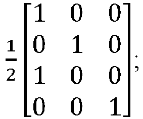
ora fully coherent codebook, a partially coherent codebook, and a non-coherent codebook. - The network device according to claim 26, wherein the first delivery module is further configured to:
if the number of antenna ports for each SRS resource in the SRS resource set is different, the number of uplink transmission antenna ports is 4, and the SRS resource set comprises two SRS resources, with one SRS resource comprising one antenna port and the other SRS resource comprising four antenna ports, then:if the uplink transmission rank is 2, determine the precoding codebook to be: if the uplink transmission rank is 3, determine the precoding codebook to be:
- The network device according to claim 26, wherein the first delivery module is further configured to:if the number of antenna ports for each SRS resource in the SRS resource set is different, the number of uplink transmission antenna ports is 4, the uplink transmission rank is 3, and the SRS resource set comprises three SRS resources, with one SRS resource comprising one antenna port, a second SRS resource comprising two antenna ports, and a third SRS resource comprising four antenna ports, determine the precoding codebook to be:

ora fully coherent codebook, a partially coherent codebook, and a non-coherent codebook. - The network device according to claim 26, further comprising:
a second delivery module, configured to: when the uplink full-power transmission capability reported by the terminal device is received, deliver an uplink full-power transmission indication to the terminal device, wherein the uplink full-power transmission indication is used to indicate that the terminal device is to use an uplink full-power transmission mode for uplink transmission. - The network device according to claim 33, wherein the second delivery module is further configured to:deliver the uplink full-power transmission indication through radio resource control RRC, medium access control MAC, or downlink control information DCI; ordeliver a full-power transmission TPMI; orconfigure, for the terminal device, an SRS resource corresponding to the precoding codebook, wherein the number of antenna ports of the configured SRS resource is the same as the number of non-zero antenna ports indicated by the precoding codebook; whereinthe non-zero antenna port means that row values of a precoding codebook corresponding to the antenna port are all non-zero.
- A terminal device, comprising:a memory, storing a computer program instruction; anda processor, wherein when the computer program instruction is executed by the processor, the uplink full-power transmission method according to any one of claims 1 to 7 is implemented.
- A network device, comprising:a memory, storing a computer program instruction; anda processor, wherein when the computer program instruction is executed by the processor, the uplink full-power transmission method according to any one of claims 8 to 17 is implemented.
- A computer-readable storage medium, wherein the computer-readable storage medium comprises an instruction, and when the instruction is run on a computer, the computer executes the uplink full-power transmission method according to any one of claims 1 to 7.
- A computer-readable storage medium, wherein the computer-readable storage medium comprises an instruction, and when the instruction is run on a computer, the computer executes the uplink full-power transmission method according to any one of claims 8 to 17.
Applications Claiming Priority (2)
| Application Number | Priority Date | Filing Date | Title |
|---|---|---|---|
| CN201910727566.7A CN111800850B (en) | 2019-08-07 | 2019-08-07 | Uplink full power transmission method and device |
| PCT/CN2020/103592 WO2021023013A1 (en) | 2019-08-07 | 2020-07-22 | Uplink full-power transmission method and device |
Publications (2)
| Publication Number | Publication Date |
|---|---|
| EP4013139A1 true EP4013139A1 (en) | 2022-06-15 |
| EP4013139A4 EP4013139A4 (en) | 2022-10-12 |
Family
ID=72805450
Family Applications (1)
| Application Number | Title | Priority Date | Filing Date |
|---|---|---|---|
| EP20849184.5A Pending EP4013139A4 (en) | 2019-08-07 | 2020-07-22 | METHOD AND DEVICE FOR FULL POWER UPLINK TRANSMISSION |
Country Status (11)
| Country | Link |
|---|---|
| US (2) | US12309709B2 (en) |
| EP (1) | EP4013139A4 (en) |
| JP (2) | JP2022543595A (en) |
| KR (1) | KR102680106B1 (en) |
| CN (1) | CN111800850B (en) |
| AU (1) | AU2020324166B2 (en) |
| BR (1) | BR112022001816A2 (en) |
| CA (1) | CA3148206A1 (en) |
| MX (1) | MX2022001466A (en) |
| UA (1) | UA129472C2 (en) |
| WO (1) | WO2021023013A1 (en) |
Cited By (1)
| Publication number | Priority date | Publication date | Assignee | Title |
|---|---|---|---|---|
| GB2622874A (en) * | 2022-09-30 | 2024-04-03 | Nokia Technologies Oy | Apparatus, method and computer program |
Families Citing this family (12)
| Publication number | Priority date | Publication date | Assignee | Title |
|---|---|---|---|---|
| CN114223283A (en) * | 2019-06-14 | 2022-03-22 | 株式会社Ntt都科摩 | Terminal and wireless communication method |
| CN114978247B (en) * | 2021-02-24 | 2025-03-04 | 华为技术有限公司 | A method and device for determining a full-power transmission codebook subset |
| CN115150927A (en) * | 2021-03-30 | 2022-10-04 | 南宁富联富桂精密工业有限公司 | Terminal and method for determining uplink transmit power |
| WO2022205459A1 (en) * | 2021-04-02 | 2022-10-06 | Oppo广东移动通信有限公司 | Wireless communication method, terminal device, and network device |
| CN115333584B (en) * | 2021-05-10 | 2024-02-20 | 维沃移动通信有限公司 | Precoding matrix indication method, terminal and network side equipment |
| CN116095803B (en) * | 2021-11-05 | 2026-03-17 | 大唐移动通信设备有限公司 | SRS transmission power determination method, equipment, device and storage medium |
| CN116248155B (en) * | 2021-12-08 | 2025-09-30 | 北京紫光展锐通信技术有限公司 | Uplink transmission method, device and readable storage medium |
| US12225474B2 (en) * | 2022-02-24 | 2025-02-11 | T-Mobile Innovation LLC | Uplink transmission power adjustment in 5G NR communication networks |
| CN118590977A (en) * | 2023-03-01 | 2024-09-03 | 华为技术有限公司 | Power control method, communication device and system |
| WO2024229705A1 (en) * | 2023-05-09 | 2024-11-14 | Apple Inc. | Full power transmission support for transmitter (tx) uplinks (uls) in a wireless network |
| CN120499843A (en) * | 2024-02-08 | 2025-08-15 | 荣耀终端股份有限公司 | Method for configuring resources and communication device |
| US20250380285A1 (en) * | 2024-06-06 | 2025-12-11 | Qualcomm Incorporated | Compression level based on nonlinearity capability |
Family Cites Families (8)
| Publication number | Priority date | Publication date | Assignee | Title |
|---|---|---|---|---|
| CN101959200B (en) * | 2009-07-20 | 2014-04-16 | 电信科学技术研究院 | Method, system and device for adjusting cell coverage area |
| CN101674642B (en) * | 2009-09-29 | 2014-04-30 | 中兴通讯股份有限公司 | Method and system for controlling transmitted power of multi-antenna terminal |
| CN102547949B (en) * | 2010-12-22 | 2015-07-01 | 中国移动通信集团江苏有限公司 | Power control method and device in mobile communication system |
| CN102932930B (en) * | 2011-08-10 | 2015-03-18 | 华为技术有限公司 | Resource scheduling method, wireless access equipment and communication system |
| CN103037488B (en) * | 2012-12-07 | 2015-10-07 | 北京北方烽火科技有限公司 | A kind of LTE ascending power control method and relevant device |
| MX350620B (en) * | 2013-08-09 | 2017-09-11 | Ericsson Telefon Ab L M | Mobile terminal, first wireless network access point and methods performed therein. |
| CN110710281B (en) | 2017-05-04 | 2022-06-14 | Lg 电子株式会社 | Method for transmitting and receiving uplink in wireless communication system and apparatus therefor |
| CN110475330B (en) * | 2018-05-11 | 2021-05-25 | 电信科学技术研究院有限公司 | Uplink power control method, terminal and network equipment |
-
2019
- 2019-08-07 CN CN201910727566.7A patent/CN111800850B/en active Active
-
2020
- 2020-07-22 KR KR1020227005210A patent/KR102680106B1/en active Active
- 2020-07-22 WO PCT/CN2020/103592 patent/WO2021023013A1/en not_active Ceased
- 2020-07-22 MX MX2022001466A patent/MX2022001466A/en unknown
- 2020-07-22 UA UAA202200899A patent/UA129472C2/en unknown
- 2020-07-22 CA CA3148206A patent/CA3148206A1/en active Pending
- 2020-07-22 AU AU2020324166A patent/AU2020324166B2/en active Active
- 2020-07-22 JP JP2022506626A patent/JP2022543595A/en active Pending
- 2020-07-22 EP EP20849184.5A patent/EP4013139A4/en active Pending
- 2020-07-22 BR BR112022001816A patent/BR112022001816A2/en unknown
-
2022
- 2022-01-27 US US17/586,318 patent/US12309709B2/en active Active
-
2023
- 2023-05-19 JP JP2023083146A patent/JP7646732B2/en active Active
-
2025
- 2025-04-23 US US19/187,116 patent/US20250254625A1/en active Pending
Cited By (2)
| Publication number | Priority date | Publication date | Assignee | Title |
|---|---|---|---|---|
| GB2622874A (en) * | 2022-09-30 | 2024-04-03 | Nokia Technologies Oy | Apparatus, method and computer program |
| US12604281B2 (en) | 2022-09-30 | 2026-04-14 | Nokia Technologies Oy | Apparatus, method and computer program for precoding |
Also Published As
| Publication number | Publication date |
|---|---|
| CN111800850A (en) | 2020-10-20 |
| US12309709B2 (en) | 2025-05-20 |
| JP2022543595A (en) | 2022-10-13 |
| AU2020324166A1 (en) | 2022-02-24 |
| UA129472C2 (en) | 2025-05-07 |
| AU2020324166B2 (en) | 2023-09-14 |
| BR112022001816A2 (en) | 2022-03-29 |
| KR20220038095A (en) | 2022-03-25 |
| KR102680106B1 (en) | 2024-06-28 |
| CN111800850B (en) | 2021-12-21 |
| MX2022001466A (en) | 2022-02-22 |
| JP7646732B2 (en) | 2025-03-17 |
| JP2023103443A (en) | 2023-07-26 |
| CA3148206A1 (en) | 2021-02-11 |
| US20250254625A1 (en) | 2025-08-07 |
| WO2021023013A1 (en) | 2021-02-11 |
| EP4013139A4 (en) | 2022-10-12 |
| US20220150841A1 (en) | 2022-05-12 |
Similar Documents
| Publication | Publication Date | Title |
|---|---|---|
| US12309709B2 (en) | Uplink full-power transmission method and device | |
| US12219370B2 (en) | Channel information determining method, network device, and terminal device | |
| US11729651B2 (en) | Reference signal measurement reporting method, user equipment and network device | |
| US20220376876A1 (en) | Channel state information csi report feedback method, terminal device and network device | |
| US11968699B2 (en) | Radio communication method and device | |
| CN108282211B (en) | A signal transmission method, network equipment and terminal equipment | |
| US11394521B2 (en) | Resource allocation indication and receiving methods and devices | |
| US20220302980A1 (en) | Method for reporting information, method for indicating information, terminal device, and network device | |
| US20220053427A1 (en) | Srs power control method and device | |
| EP4280758A1 (en) | Beam indication method, network device, and terminal device | |
| US10299267B2 (en) | Data transmission method and user equipment | |
| US12192137B2 (en) | Object receiving method and device | |
| EP4633229A1 (en) | Aperiodic cli reporting method and apparatus, and computer-readable storage medium | |
| HK40067826A (en) | Uplink full-power transmission method and device | |
| RU2794467C1 (en) | Method and apparatus for uplink data transmission at full power | |
| EP3668160B1 (en) | Signal reporting method and terminal device | |
| US12401399B2 (en) | Transmit precoding matrix indicator design for 8 transmit antenna uplink operation | |
| US12634085B2 (en) | Sounding reference signal resource indicator design for 8 transmit antenna uplink operation | |
| US20240056260A1 (en) | Sounding Reference Signal Resource Indicator Design for 8 Transmit Antenna Uplink Operation | |
| HK40078059A (en) | Information submission and instruction method, terminal device and network apparatus | |
| HK40072202B (en) | Method for determining channel information, network device and terminal device | |
| HK40072202A (en) | Method for determining channel information, network device and terminal device |
Legal Events
| Date | Code | Title | Description |
|---|---|---|---|
| STAA | Information on the status of an ep patent application or granted ep patent |
Free format text: STATUS: THE INTERNATIONAL PUBLICATION HAS BEEN MADE |
|
| PUAI | Public reference made under article 153(3) epc to a published international application that has entered the european phase |
Free format text: ORIGINAL CODE: 0009012 |
|
| STAA | Information on the status of an ep patent application or granted ep patent |
Free format text: STATUS: REQUEST FOR EXAMINATION WAS MADE |
|
| 17P | Request for examination filed |
Effective date: 20220208 |
|
| AK | Designated contracting states |
Kind code of ref document: A1 Designated state(s): AL AT BE BG CH CY CZ DE DK EE ES FI FR GB GR HR HU IE IS IT LI LT LU LV MC MK MT NL NO PL PT RO RS SE SI SK SM TR |
|
| REG | Reference to a national code |
Ref country code: HK Ref legal event code: DE Ref document number: 40067826 Country of ref document: HK |
|
| A4 | Supplementary search report drawn up and despatched |
Effective date: 20220913 |
|
| RIC1 | Information provided on ipc code assigned before grant |
Ipc: H04L 5/00 20060101ALI20220907BHEP Ipc: H04W 52/42 20090101ALI20220907BHEP Ipc: H04W 52/36 20090101ALI20220907BHEP Ipc: H04W 52/14 20090101ALI20220907BHEP Ipc: H04W 52/18 20090101AFI20220907BHEP |
|
| DAV | Request for validation of the european patent (deleted) | ||
| DAX | Request for extension of the european patent (deleted) | ||
| STAA | Information on the status of an ep patent application or granted ep patent |
Free format text: STATUS: EXAMINATION IS IN PROGRESS |
|
| 17Q | First examination report despatched |
Effective date: 20250303 |
|
| GRAP | Despatch of communication of intention to grant a patent |
Free format text: ORIGINAL CODE: EPIDOSNIGR1 |
|
| STAA | Information on the status of an ep patent application or granted ep patent |
Free format text: STATUS: GRANT OF PATENT IS INTENDED |
|
| INTG | Intention to grant announced |
Effective date: 20251006 |
|
| GRAJ | Information related to disapproval of communication of intention to grant by the applicant or resumption of examination proceedings by the epo deleted |
Free format text: ORIGINAL CODE: EPIDOSDIGR1 |
|
| STAA | Information on the status of an ep patent application or granted ep patent |
Free format text: STATUS: EXAMINATION IS IN PROGRESS |
|
| INTC | Intention to grant announced (deleted) |