EP4013029A1 - Support for camera and electronic apparatus - Google Patents
Support for camera and electronic apparatus Download PDFInfo
- Publication number
- EP4013029A1 EP4013029A1 EP20894303.5A EP20894303A EP4013029A1 EP 4013029 A1 EP4013029 A1 EP 4013029A1 EP 20894303 A EP20894303 A EP 20894303A EP 4013029 A1 EP4013029 A1 EP 4013029A1
- Authority
- EP
- European Patent Office
- Prior art keywords
- side wall
- camera
- elastic
- bracket
- mounting hole
- Prior art date
- Legal status (The legal status is an assumption and is not a legal conclusion. Google has not performed a legal analysis and makes no representation as to the accuracy of the status listed.)
- Ceased
Links
- 239000013013 elastic material Substances 0.000 claims description 24
- 229920003023 plastic Polymers 0.000 claims description 10
- 239000004033 plastic Substances 0.000 claims description 10
- 239000002184 metal Substances 0.000 claims description 7
- 238000011982 device technology Methods 0.000 abstract description 2
- 238000000926 separation method Methods 0.000 description 17
- 238000013461 design Methods 0.000 description 16
- 239000000463 material Substances 0.000 description 12
- 238000007639 printing Methods 0.000 description 11
- 230000000694 effects Effects 0.000 description 7
- 238000000034 method Methods 0.000 description 7
- 230000008569 process Effects 0.000 description 7
- 238000010586 diagram Methods 0.000 description 6
- 238000000465 moulding Methods 0.000 description 6
- 238000012545 processing Methods 0.000 description 6
- 238000001746 injection moulding Methods 0.000 description 3
- 230000008901 benefit Effects 0.000 description 2
- 230000006835 compression Effects 0.000 description 2
- 238000007906 compression Methods 0.000 description 2
- 230000003993 interaction Effects 0.000 description 2
- 229920001875 Ebonite Polymers 0.000 description 1
- 239000003086 colorant Substances 0.000 description 1
- 238000011161 development Methods 0.000 description 1
- 230000005489 elastic deformation Effects 0.000 description 1
- 238000005516 engineering process Methods 0.000 description 1
- 229920002457 flexible plastic Polymers 0.000 description 1
- 230000006872 improvement Effects 0.000 description 1
- 230000000116 mitigating effect Effects 0.000 description 1
- 238000012986 modification Methods 0.000 description 1
- 230000004048 modification Effects 0.000 description 1
- 238000012216 screening Methods 0.000 description 1
- 239000000243 solution Substances 0.000 description 1
Images




Classifications
-
- H—ELECTRICITY
- H04—ELECTRIC COMMUNICATION TECHNIQUE
- H04N—PICTORIAL COMMUNICATION, e.g. TELEVISION
- H04N23/00—Cameras or camera modules comprising electronic image sensors; Control thereof
- H04N23/50—Constructional details
- H04N23/54—Mounting of pick-up tubes, electronic image sensors, deviation or focusing coils
-
- H—ELECTRICITY
- H04—ELECTRIC COMMUNICATION TECHNIQUE
- H04M—TELEPHONIC COMMUNICATION
- H04M1/00—Substation equipment, e.g. for use by subscribers
- H04M1/02—Constructional features of telephone sets
- H04M1/0202—Portable telephone sets, e.g. cordless phones, mobile phones or bar type handsets
- H04M1/026—Details of the structure or mounting of specific components
- H04M1/0264—Details of the structure or mounting of specific components for a camera module assembly
-
- F—MECHANICAL ENGINEERING; LIGHTING; HEATING; WEAPONS; BLASTING
- F16—ENGINEERING ELEMENTS AND UNITS; GENERAL MEASURES FOR PRODUCING AND MAINTAINING EFFECTIVE FUNCTIONING OF MACHINES OR INSTALLATIONS; THERMAL INSULATION IN GENERAL
- F16B—DEVICES FOR FASTENING OR SECURING CONSTRUCTIONAL ELEMENTS OR MACHINE PARTS TOGETHER, e.g. NAILS, BOLTS, CIRCLIPS, CLAMPS, CLIPS OR WEDGES; JOINTS OR JOINTING
- F16B2/00—Friction-grip releasable fastenings
- F16B2/20—Clips, i.e. with gripping action effected solely by the inherent resistance to deformation of the material of the fastening
- F16B2/22—Clips, i.e. with gripping action effected solely by the inherent resistance to deformation of the material of the fastening of resilient material, e.g. rubbery material
-
- F—MECHANICAL ENGINEERING; LIGHTING; HEATING; WEAPONS; BLASTING
- F16—ENGINEERING ELEMENTS AND UNITS; GENERAL MEASURES FOR PRODUCING AND MAINTAINING EFFECTIVE FUNCTIONING OF MACHINES OR INSTALLATIONS; THERMAL INSULATION IN GENERAL
- F16M—FRAMES, CASINGS OR BEDS OF ENGINES, MACHINES OR APPARATUS, NOT SPECIFIC TO ENGINES, MACHINES OR APPARATUS PROVIDED FOR ELSEWHERE; STANDS; SUPPORTS
- F16M11/00—Stands or trestles as supports for apparatus or articles placed thereon ; Stands for scientific apparatus such as gravitational force meters
- F16M11/20—Undercarriages with or without wheels
- F16M11/22—Undercarriages with or without wheels with approximately constant height, e.g. with constant length of column or of legs
-
- F—MECHANICAL ENGINEERING; LIGHTING; HEATING; WEAPONS; BLASTING
- F16—ENGINEERING ELEMENTS AND UNITS; GENERAL MEASURES FOR PRODUCING AND MAINTAINING EFFECTIVE FUNCTIONING OF MACHINES OR INSTALLATIONS; THERMAL INSULATION IN GENERAL
- F16M—FRAMES, CASINGS OR BEDS OF ENGINES, MACHINES OR APPARATUS, NOT SPECIFIC TO ENGINES, MACHINES OR APPARATUS PROVIDED FOR ELSEWHERE; STANDS; SUPPORTS
- F16M13/00—Other supports for positioning apparatus or articles; Means for steadying hand-held apparatus or articles
- F16M13/02—Other supports for positioning apparatus or articles; Means for steadying hand-held apparatus or articles for supporting on, or attaching to, an object, e.g. tree, gate, window-frame, cycle
-
- H—ELECTRICITY
- H04—ELECTRIC COMMUNICATION TECHNIQUE
- H04N—PICTORIAL COMMUNICATION, e.g. TELEVISION
- H04N23/00—Cameras or camera modules comprising electronic image sensors; Control thereof
- H04N23/50—Constructional details
- H04N23/51—Housings
-
- H—ELECTRICITY
- H04—ELECTRIC COMMUNICATION TECHNIQUE
- H04N—PICTORIAL COMMUNICATION, e.g. TELEVISION
- H04N23/00—Cameras or camera modules comprising electronic image sensors; Control thereof
- H04N23/57—Mechanical or electrical details of cameras or camera modules specially adapted for being embedded in other devices
Definitions
- This application relates to the field of electronic device technologies, and in particular, to a camera bracket and an electronic device.
- An electronic device is usually provided with a camera, and shoots an external environment by using the camera.
- the camera is usually mounted in a housing of the electronic device by using a bracket. To improve a shooting effect of the camera, it needs to be ensured that the camera is located at a proper position and is prevented from shaking.
- This application provides a camera bracket and an electronic device.
- the bracket can improve position precision of a camera, and mitigate a shaking risk of the camera.
- a first aspect of this application provides a camera bracket.
- the bracket includes a mounting frame, a mounting hole is provided in the mounting frame, and the mounting hole is configured to mount a camera.
- Side walls of the mounting hole include an elastic side wall and a non-elastic side wall. Hardness of the elastic side wall is less than that of the non-elastic side wall, and the elastic side wall and the non-elastic side wall are configured to be in contact with the camera. There may be one or more mounting holes. One camera may be mounted in each mounting hole.
- the bracket can facilitate mounting the camera in the mounting hole, and can also improve mounting reliability, and mitigate a shaking risk of the camera in the mounting hole.
- only an elastic structure is added on the bracket, to reduce costs.
- an elastic material of the elastic side wall is of an integrated structure, or the elastic material of the elastic side wall is of a separated structure.
- an elastic pad is disposed on the mounting frame.
- the elastic pad includes convex portions, the convex portions protrude toward inside of the mounting hole, and the convex portions form the elastic side wall.
- the elastic pad includes a plurality of the convex portions that are spaced.
- a concave portion is formed between adjacent convex portions.
- the convex portions can deform toward the concave portions, to facilitate compression and deformation of the convex portions, thereby further reducing mounting difficulty of the camera.
- the concave portions can further alleviate stress concentration between the convex portions and the camera, to mitigate a risk of damaging the bracket and the camera in a mounting process.
- the elastic pad further includes a first body portion.
- the first body portion is connected to the mounting frame, and the convex portions protrude relative to the first body portion.
- the convex portions in interference fit with the camera are connected to form an integrated structure by using the first body portion.
- the elastic pad is enabled to be of an integrated structure.
- the elastic pad of the integrated structure has an advantage of processing convenience, and can improve reliability of connection between the convex portions and the mounting frame, thereby improving mounting reliability of the camera.
- the elastic pad includes a plurality of convex portions.
- the convex portions are of separated structures, and are connected to the mounting frame.
- usage of elastic materials can be reduced, to help reduce a weight and a size of the electronic device.
- the elastic pad includes flexible rubber.
- the mounting frame includes metal or hard plastic, and the elastic pad and the mounting frame are integrally formed or fixedly connected.
- the mounting hole is of a square structure, and the side walls of the mounting hole include a first side wall and a second side wall that are disposed opposite to each other, and a third side wall and a fourth side wall that are disposed opposite to each other.
- At least one part of one of the first side wall and the second side wall is the elastic side wall, and the other side wall is the non-elastic side wall; and at least one part of one of the third side wall and the fourth side wall is the elastic side wall, and the other side wall is the non-elastic side wall.
- the mounting hole is of a circular structure
- the elastic side wall is of an arc-shaped structure
- the non-elastic side wall is of an arc-shaped structure
- Shore hardness of the elastic material of the elastic side wall is in a range of 65 to 75.
- a second aspect of this application provides a camera module.
- the camera module includes a camera and a bracket, the bracket is the foregoing bracket, and the camera is mounted in a mounting hole of the bracket.
- a third aspect of this application provides an electronic device.
- the electronic device includes a housing, a middle frame, a display, and a camera module.
- the camera module includes:
- the camera module and the display are mounted on the middle frame.
- the camera has relatively high position precision, and a relatively low shaking risk.
- the camera is in interference fit with the elastic side wall, and a magnitude of interference between the camera and the elastic side wall is in a range of 0.01 mm to 0.1 mm. In this way, the shaking risk of the camera can be mitigated, and structural strength of the bracket and the camera can be improved.
- the camera abuts against the non-elastic side wall.
- a contact area between the elastic side wall and the camera is in a range of 3 mm2 to 6 mm2. This can improve mounting reliability of the camera in the mounting hole and reduce a mounting difficulty of the camera.
- the camera decorating part includes an accommodating groove, and the bracket is located in the accommodating groove; limiting protrusions are also provided on the camera decorating part, a part of the limiting protrusions are located on two ends along a length direction of the bracket, and a part of the limiting protrusions are located on two ends along a width direction of the bracket; and the limiting protrusions abut against the bracket.
- the limiting protrusions when the limiting protrusions are used, the shaking risk of the bracket along the length direction and the width direction can be mitigated, to improve the position precision of the bracket.
- An electronic device includes components such as a housing, a middle frame, a camera, a display, a battery, and a camera decorating part.
- the battery is mounted on a battery rear cover, and components such as the camera and the display are mounted on the middle frame.
- the camera is mounted by using a bracket, the bracket is mounted in the camera decorating part, and the camera decorating part is mounted on the battery rear cover.
- a camera lens is mounted on the camera decorating part.
- the camera corresponds to the camera lens, and can shoot an external environment through the camera lens.
- silk printing is usually performed on the camera lens, and a silk printing central hole is formed after the silk printing.
- the silk printing hole is light-permeable.
- the camera needs to be concentric with the silk printing central hole.
- a degree of eccentricity between the camera and a camera lens silk screening hole needs to be reduced.
- position precision of the camera after the camera is mounted needs to be improved, and a shaking risk of the camera needs to be mitigated.
- the technical problem is resolved in the conventional technology in the following two manners.
- the camera is fixed to the bracket through dispensing, and it is ensured to the greatest extent that the camera is concentric with the silk printing central hole of the camera lens, and the degree of eccentricity of the camera is reduced.
- dispensing needs to be performed by using a dispensing device, and costs are relatively high.
- the camera is in clearance fit with the bracket, and relative positions of the camera and the bracket can be adjusted by using a clearance between the camera and the bracket, to reduce the degree of eccentricity of the camera.
- the clearance between the camera and the bracket causes relative shaking between the camera and the bracket, resulting in eccentricity of the camera.
- position precision of a camera 3 is improved and shaking of the camera 3 is alleviated mainly by improving a specific structure of a bracket 1 of the camera 3.
- an embodiment of this application provides a bracket 1 of a camera 3.
- the bracket 1 includes a mounting frame 11, a mounting hole may be provided in the mounting frame 11, and the mounting hole is configured to mount the camera 3.
- the mounting frame 11 is of a structure with specific strength and rigidity.
- the mounting frame 11 may be made of a material with specific hardness, such as hard rubber or metal, provided that structural strength for mounting the camera 3 can be satisfied.
- the mounting frame 11 may specifically include one or more mounting holes.
- the mounting frame 11 includes three mounting holes: a first mounting hole 131, a second mounting hole 132, and a third mounting hole 133. Therefore, the mounting frame 11 may be configured to mount three cameras 3.
- the mounting frame 11 may alternatively include one, two, or more mounting holes. A quantity of mounting holes is not limited in this application.
- side walls of the mounting hole include elastic side walls and non-elastic side walls.
- a shape of the mounting hole is approximately a rectangle, and the mounting hole includes fourth side walls: a first side wall 15 and a second side wall 16 that are disposed opposite to each other, and a third side wall 17 and a fourth side wall 18 that are disposed opposite to each other.
- some are elastic side walls, and the others are non-elastic side walls.
- the first side wall 15 and the second side wall 16 that are disposed opposite to each other the first side wall 15 is an elastic side wall, and the second side wall 16 is a non-elastic side wall; and in the third side wall 17 and the fourth side wall 18 that are disposed opposite to each other, the third side wall 17 is an elastic side wall, and the fourth side wall 18 is a non-elastic side wall.
- the second side wall 16 and the fourth side wall 18 may be set to elastic side walls, and the first side wall 15 and the third side wall 17 may be set to non-elastic side walls.
- Hardness of the elastic side wall is less than that of the non-elastic side wall, and the elastic side wall and the non-elastic side wall are configured to be in contact with the camera.
- the non-elastic side wall mentioned in this application does not mean that the side wall cannot elastically deform, but means that an amount of elastic deformation of the non-elastic side wall is relatively small and is less than an amount of deformation of the elastic side wall.
- the non-elastic side wall may be formed by the mounting frame 11, and the mounting frame 11 is of a structure with relatively large hardness, so that the non-elastic side wall is of a structure with relatively large hardness.
- the elastic side wall may be formed of a rubber material with specific elasticity, so that hardness of the elastic side wall is less than that of the non-elastic side wall.
- the elastic side wall in this embodiment is not necessarily a continuous side wall, and may alternatively be a discontinuous side wall.
- the elastic side wall in this embodiment is a filling region (the filling region is continuous) of elastic materials.
- the elastic materials may be filled at intervals or continuously in the filling region, and regardless of whether the elastic materials are filled at intervals or continuously, the elastic materials in the filling region form an elastic side wall of a mounting hole.
- the foregoing non-elastic side wall is a non-filling region (the non-filling region is continuous). There is no elastic material in the non-filling region.
- the non-elastic side wall is a continuous side wall.
- the camera 3 when the camera 3 is mounted in the mounting hole, the camera 3 is in interference fit with an elastic side wall of the mounting hole, and can compress the elastic side wall. After fitting ends, the elastic side wall springs back, so that the camera 3 abuts against a non-elastic side wall (the mounting frame 11) of the mounting hole, the camera 3 is reliably mounted, and the camera and the bracket form a camera module.
- the elastic side wall in a process in which the camera 3 is mounted in the mounting hole, can deform after being compressed, so that an area of the mounting hole can be increased, thereby facilitating mounting the camera 3 in the mounting hole.
- the elastic side wall can spring back after the camera 3 is mounted, so that the camera 3 abuts against the non-elastic side wall of the mounting hole. This improves the mounting reliability, mitigates a shaking risk of the camera 3 in the mounting hole, and reduces the degree of eccentricity of the camera 3, thereby improving a shooting effect of the camera 3 and the appearance and performance of the electronic device.
- dispensing is not required, provided that an elastic structure is added on the bracket 1, so that costs can be reduced.
- a magnitude of interference between the elastic side wall and the camera 3 should not be excessively large.
- the magnitude of interference between the elastic side wall and the camera 3 is excessively large, during mounting of the camera 3, an interaction force between the elastic side wall and the camera 3 is relatively large, affecting strength of the elastic side wall and the camera 3.
- the magnitude of interference between the elastic side wall and the camera 3 is excessively small, after the camera 3 is mounted, the camera 3 has a risk of shaking in the mounting hole, resulting in relatively low mounting reliability of the camera 3.
- the magnitude of interference between the elastic side wall and the camera 3 may be in a range of 0.01 mm to 0.1 mm. In this way, the shaking risk of the camera 3 can be mitigated, and structural strength of the bracket 1 and the camera 3 can be improved.
- the magnitude of interference between the elastic side wall and the camera 3 may be 0.05 mm, 0.08 mm, or the like.
- the magnitude of interference between the elastic side wall and the camera 3 may be set according to structures and sizes of the elastic side wall and the camera 3.
- a larger contact area between the elastic side wall and the camera 3 indicates a larger stress between the elastic side wall and the camera 3, as well as higher assembling difficulty, but higher mounting reliability of the camera 3 in the mounting hole.
- a smaller contact area between the elastic side wall and the camera 3 indicates a smaller stress between the elastic side wall and the camera 3, as well as lower mounting reliability of the camera 3 in the mounting hole, but lower processing difficulty, and a lower risk of damaging the bracket 1 and the camera 3 in the mounting process.
- the contact area between the elastic side wall and the camera 3 should not be excessively small, and should not be excessively large, either, and may be specifically in a range of 3 mm2 to 6 mm2, for example, 4 mm2 or 5 mm2.
- the contact area between the camera 3 and the elastic side wall may be properly determined based on a shape and a size of the camera 3.
- Shore hardness of the elastic side wall of the mounting hole may be in a range of 65 to 75, for example, 68, 70, or 72.
- a material with the hardness may be specifically flexible rubber or flexible plastic.
- an elastic pad 14 is disposed on the mounting frame 11.
- the elastic pad 14 is made of a material with specific elasticity and relatively small hardness. When an external force is applied to the elastic pad 14, the elastic pad 14 can elastically deform, and when the external force is reduced or disappears, the elastic pad 14 can spring back.
- the elastic pad 14 is disposed on the mounting frame 11, so that the elastic pad 14 forms the elastic side wall of the mounting hole, and the mounting frame 11 on which the elastic pad 14 is not disposed is used as the non-elastic side wall of the mounting hole.
- the elastic pad 14 may include a plurality of spaced convex portions 141.
- the convex portions 141 protrude toward inside of the mounting hole.
- the convex portions 141 form the elastic side wall of the mounting hole.
- a contact area between the camera 3 and the convex portion 141 may be in a range of 3 mm2 to 6 mm2.
- a cross-sectional area of the convex portion 141 may be in a range of 3 mm2 to 6 mm2. In this way, the mounting reliability of the camera 3 in the mounting hole can be improved, and the mounting difficulty of the camera 3 can be reduced.
- a shape of the convex portion 141 may be a square, a circle, or another common shape, provided that the contact area between the convex portion 141 and the camera 3 is proper.
- a width of the convex portion 141 is in a range of 1 mm to 2 mm, and may be specifically 1.5 mm.
- the width of the convex portion 141 may be a size in a direction Y shown in FIG. 7 .
- the elastic pad 14 may include a plurality of convex portions 141, and adjacent convex portions 141 are spaced from each other.
- a plurality spaced convex portions 141 form the elastic side wall of the mounting hole.
- the camera 3 is mounted in the mounting hole, the camera 3 is in interference fit with each convex portion 141, and a contact area between each convex portion 141 and a camera 3 may be in a range of 3 mm2 to 6 mm2.
- the cross-sectional area of the convex portion 141 may be in a range of 3 mm2 to 6 mm2.
- a larger quantity of convex portions 141 of the elastic pad 14 indicates a larger contact area between the elastic pad 14 and each camera 3, and higher reliability of connection between the elastic pad 14 and the camera 3. In this way, the mounting reliability of the camera 3 in the mounting hole can be improved, and the mounting difficulty of the camera 3 can be reduced.
- the elastic side wall of the mounting hole is of a discontinuous structure.
- a plurality of spaced convex portions 141 form the elastic side wall, and a region in which the convex portions 141 are located is a filling region of the side wall of the mounting hole.
- a concave portion 142 is formed between adjacent convex portions 141.
- the convex portions 141 can deform toward the concave portions 142.
- settings of the concave portions 142 can provide space for deformation of the convex portions 141. This facilitates compression and deformation of the convex portions 141, thereby further reducing the mounting difficulty of the camera 3.
- the concave portions 142 can further alleviate stress concentration between the convex portions 141 and the camera 3, to mitigate the risk of damaging the bracket 1 and the camera 3 in the mounting process.
- the elastic pad 14 includes a first body portion 143 and the convex portions 141.
- the first body portion 143 and the convex portions 141 are fixedly connected or integrally formed.
- the first body portion 143 is connected to the mounting frame 11, and the convex portions 141 protrude relative to the first body portion 143.
- the convex portions 141 in interference fit with the camera 3 are connected into an integrated structure by using the first body portion 143, so that the elastic pad 14 is of an integrated structure.
- the convex portions 141 are connected to the mounting frame 11 by using the first body portion 143.
- the elastic pad 14 of the integrated structure has an advantage of processing convenience, and can improve reliability of connection between the convex portions 141 and the mounting frame 11, thereby improving the mounting reliability of the camera 3.
- the elastic pad 14 may alternatively include only a plurality of convex portions 141, and the convex portions 141 are of separated structures. When the convex portions 141 are connected to the mounting frame 11, the elastic pad 141 is formed. In this embodiment, when the elastic pad 14 of a separated structure is used, usage of elastic materials can be reduced, to help reduce a weight and a size of the electronic device.
- the elastic pad 14 includes a flexible rubber material.
- Flexible rubber is a material formed through plastic injection molding, and has a feature of relatively small hardness.
- the flexible rubber can spring back after forced deformation.
- the mounting frame 11 may include a metal or hard plastic material.
- Hard plastic is a material formed through plastic injection molding, and has a feature of relatively high hardness. In addition, hardness of the hard plastic is greater than that of the flexible rubber, and an elastic coefficient of the hard plastic is less than that of the flexible rubber.
- the elastic pad 14 and the mounting frame 11 may be integrally formed through double-shot molding.
- the bracket 1 (including the mounting frame 11 and the elastic pad 14) may be of an integrally formed structure.
- the double-shot molding means inject-molding two different materials into a same set of mold, to implement a forming process in which a part formed through injection molding is formed of two materials.
- the two materials may be materials with different colors or different hardness.
- the flexible rubber and metal may be formed into the bracket 1 through double-shot molding, or the hard plastic and the metal may be formed into the bracket 1 through double-shot molding.
- the mounting hole of the mounting frame 11 is of a square structure.
- side walls of the mounting hole include the first side wall 15 and the second side wall 16 that are disposed opposite to each other, and the third side wall 17 and the fourth side wall 18 that are disposed opposite to each other.
- the first side wall 15 is adjacent to the third side wall 17 and the fourth side wall 18, and the four side walls define a mounting hole of the mounting frame 11 through enclosure.
- At least one part of the first side wall 15 is an elastic side wall.
- the foregoing elastic materials for example, the elastic pad 14
- the first side wall 15 includes an elastic side wall and a non-elastic side wall.
- the second side wall 16 disposed opposite to the first side wall 15 is a non-elastic side wall.
- no elastic materials for example, the elastic pad 14
- at least one part of one of the first side wall 15 and the second side wall 16 may be an elastic side wall, and the other side wall is a non-elastic side wall.
- at least one part of the second side wall 16 is an elastic side wall, and the first side wall 15 is a non-elastic side wall.
- the third side wall 17 is an elastic side wall.
- the foregoing elastic materials (for example, the elastic pad 14) may be filled in at least one part of the third side wall 17.
- the third side wall includes an elastic side wall and a non-elastic side wall.
- the fourth side wall 18 disposed opposite to the third side wall 17 is a non-elastic side wall.
- no elastic materials (for example, the elastic pad 14) are filled in the fourth side wall 18.
- at least one part of one of the third side wall 17 and the fourth side wall 18 may be an elastic side wall, and the other side wall is a non-elastic side wall.
- at least one part of the fourth side wall 18 is an elastic side wall, and the third side wall 17 is a non-elastic side wall.
- elastic side walls are located on two adjacent side walls of the square mounting hole.
- the elastic side walls may be disposed on the first side wall 15 and the third side wall 17 (as shown in FIG. 9 ), or the first side wall 15 and the fourth side wall 18, or the second side wall 16 and the third side wall 17, or the second side wall 16 and the fourth side wall 18.
- the elastic pad 14 disposed on the first side wall 15 may be of a continuous-shaped structure or a discontinuous-shaped structure.
- the camera 3 in a process in which the camera 3 is mounted in the mounting hole, under an effect of an external force, the camera 3 is in interference fit with the elastic materials, and the elastic materials (for example, the elastic pad) disposed on the first side wall 15 and the third side wall 17 are compressed to deform, to facilitate placing the camera 3 into the mounting hole.
- the elastic materials for example, the elastic pad
- the camera 3 has a tendency of moving toward the second side wall 16 and the fourth side wall 18, so that the camera 3 abuts against the second side wall 16 and the fourth second side wall 18, or the camera 3 is in contact with the second side wall 16 and the fourth side wall 18 without a clearance.
- an interaction force between the camera 3 and the second side wall 16 and the fourth side wall 18 is relatively small. In this way, the camera 3 is mounted.
- the camera 3 may still be in interference fit with the elastic side walls. This improves the mounting reliability of the camera 3, and reduces the degree of eccentricity of the camera 3.
- elastic pads 14 disposed on adjacent side walls are connected to each other or integrally formed, forming a structure shown in FIG. 10 .
- the elastic pad 14 is approximately L-shaped, so that areas of elastic side walls can be increased.
- the elastic pad 14 may be flexible rubber of an L-shaped structure, and the flexible rubber and hard plastic or the flexible rubber and metal are processed by using a double-shot molding process, to form the bracket 1 shown in FIG. 8 .
- elastic pads 14 on adjacent side walls may alternatively be of separated structures. In other words, two elastic pads 14 disposed on adjacent side walls are separated from each other. In this case, usage of elastic materials can be reduced.
- a separation part 12 may be disposed in the mounting frame 11.
- two separation parts 12 may be disposed, to divide the mounting frame 11 into three mounting holes: a first mounting hole 131, a second mounting hole 132, and a third mounting hole 133.
- the three mounting holes can all be configured to mount cameras 3.
- the separation part 12 may be used as elastic side walls or non-elastic side walls of the adjacent mounting holes.
- FIG. 8 as an example, in the separation part 12 between the first mounting hole 131 and the second mounting hole 132, a side facing toward inside of the first mounting hole 131 is a non-elastic side wall, and a side facing toward inside of the second mounting hole 132 is an elastic side wall. Therefore, when cameras 3 are mounted in the first mounting hole 131 and the second mounting hole 132, one camera 3 is in interference fit with the separation part 12, and the other camera 3 abuts against the separation part 12. In other words, an acting force acting on the separation part 12 is not excessively large. This improves structural strength of the separation part 12.
- both a side facing toward the second mounting hole 132 and a side facing toward the third mounting hole 133 may be non-elastic side walls. Therefore, when cameras 3 are mounted in the second mounting hole 132 and the third mounting hole 133, the two cameras 3 both abut against the separation part 12. Therefore, an acting force acting on the separation part 12 is relatively small, thereby improving structural strength of the second separation part 12.
- the two cameras 3 may both be in interference fit with the separation part 12 between the two mounting holes.
- two sides of the separation part 12 between the adjacent mounting holes may both be used as elastic side walls. In this case, an acting force acting on the second separation part 12 is relatively large.
- the mounting hole of the bracket 1 may alternatively be of a circular structure.
- a base of the camera 3 is of a circular structure matching the mounting hole. Therefore, in the mounting hole, both an elastic side wall and a non-elastic side wall may be of arc-shaped structures.
- a central angle of an elastic side wall may be the same as or different from that of a non-elastic side wall.
- the electronic device further includes components such as a camera decorating part 2, a middle frame, and a battery cover.
- the bracket 1 can be mounted in the camera decorating part 2.
- the camera decorating part 2 includes a second body portion 21 and a flange 22.
- the flange 22 is disposed on a periphery of the second body portion 21, and a mounting groove 214 is provided in the second body portion 21.
- the bracket 1 is mounted in the mounting groove 214.
- a fourth mounting hole 211, a fifth mounting hole 212, and a sixth mounting hole 213 are provided in a bottom wall of the mounting groove 214.
- the foregoing three mounting holes respectively correspond to three cameras 3.
- the bracket 1 is mounted in the camera decorating part 2
- the three cameras 3 are respectively located in the fourth mounting hole 211, the fifth mounting hole 212, and the sixth mounting hole 213.
- a camera lens 4 is disposed on a back surface of the camera decorating part 2, and the cameras 3 correspond to the camera lens 4 respectively through the fourth mounting hole 211, the fifth mounting hole 212, and the sixth mounting hole 213. In this way, an external environment can be shot through the camera lens 4, and a user can observe the cameras 3 through the camera lens 4.
- One camera lens 4 may be disposed on the camera decorating part 2, and the camera lens 4 corresponds to the cameras 3 (for example, when three cameras 3 are included, the camera lens 4 corresponds to the three cameras 3).
- a quantity of camera lenses 4 in the camera decorating part 2 may be the same as that of cameras 3 (for example, when three cameras 3 are included, the camera decorating part 2 includes three camera lenses 4), and the camera lenses 4 are in one-to-one correspondence to the cameras 3.
- a degree of concentricity between each camera 3 and a silk printing central hole in the camera lens 4 needs to be improved.
- mounting precision of the camera 3 needs to be improved, and shaking of the camera 3 in the bracket 1 needs to be alleviated.
- an elastic material is added on a side wall of the mounting hole of the bracket 1, to improve position precision of the camera 3 in the mounting hole of the bracket 1, and alleviate shaking of the camera 3 in the mounting hole.
- position precision of the bracket 1 in the camera decorating part 2 further needs to be improved, and a shaking risk of the bracket 1 in the mounting groove 214 of the camera decorating part 2 needs to be mitigated.
- limiting protrusions 221 are disposed on the flange 22 of the camera decorating part 2. Each limiting protrusion 221 abuts against the bracket 1, to alleviate shaking of the bracket 1 in the camera decorating part 2, thereby improving position precision of the bracket 1.
- limiting protrusions 221 are disposed on both two ends of the flange 22 along a length direction X of the bracket 1, and the limiting protrusions 221 located on the two ends along the length direction X can limit shaking of the bracket 1 along the length direction X.
- limiting protrusions 221 are disposed on both two ends of the flange 22 along a width direction Y of the bracket 1, and the limiting protrusions 221 located on the two ends along the width direction Y can limit shaking of the bracket 1 along the width direction Y, thereby mitigating a shaking risk of the bracket 1 in the camera decorating part 2.
- the camera 3 is first mounted on the middle frame, and then the camera 3 is connected to the bracket (the camera 3 is in interference fit with an elastic side wall of the mounting hole, and abuts against a non-elastic side wall), to form a camera module.
- the camera 3 may be first mounted on the bracket 1, to form the camera module, and then the camera module is mounted on the middle frame.
- the bracket 1 is mounted in the mounting groove 214 of the camera decorating part 2, and is limited by using the limiting protrusions 221.
- the camera lens 4 is mounted on the camera decorating part 2, so that the camera 3 is concentric with the silk printing central hole of the camera lens 4.
- the camera lens 4 may be correspondingly provided with a plurality of silk printing central holes (for example, three silk printing central holes), and the cameras 3 are enabled to correspond to the corresponding silk printing central holes.
- the camera decorating part 2 is mounted on the battery cover of the electronic device.
- the bracket 1 provided in the embodiments of this application can effectively improve the position precision of the camera 3, and mitigate the shaking risk of the camera 3, to reduce the degree of eccentricity between the camera 3 and the camera lens 4, improve the shooting effect of the camera 3, and improve the appearance and performance of the electronic device.
Landscapes
- Engineering & Computer Science (AREA)
- General Engineering & Computer Science (AREA)
- Signal Processing (AREA)
- Multimedia (AREA)
- Mechanical Engineering (AREA)
- Studio Devices (AREA)
- Camera Bodies And Camera Details Or Accessories (AREA)
Abstract
Description
- This application claims priority to
Chinese Patent Application No. 201911166970.8, filed with Chinese Patent Office on November 25, 2019 - This application relates to the field of electronic device technologies, and in particular, to a camera bracket and an electronic device.
- With development of electronic devices, users pose increasingly high requirements on performance of the electronic devices. An electronic device is usually provided with a camera, and shoots an external environment by using the camera. In the electronic device, the camera is usually mounted in a housing of the electronic device by using a bracket. To improve a shooting effect of the camera, it needs to be ensured that the camera is located at a proper position and is prevented from shaking.
- This application provides a camera bracket and an electronic device. The bracket can improve position precision of a camera, and mitigate a shaking risk of the camera.
- A first aspect of this application provides a camera bracket. The bracket includes a mounting frame, a mounting hole is provided in the mounting frame, and the mounting hole is configured to mount a camera.
- Side walls of the mounting hole include an elastic side wall and a non-elastic side wall. Hardness of the elastic side wall is less than that of the non-elastic side wall, and the elastic side wall and the non-elastic side wall are configured to be in contact with the camera. There may be one or more mounting holes. One camera may be mounted in each mounting hole.
- In this embodiment, the bracket can facilitate mounting the camera in the mounting hole, and can also improve mounting reliability, and mitigate a shaking risk of the camera in the mounting hole. In addition, during mounting of the camera, only an elastic structure is added on the bracket, to reduce costs.
- In a possible design, an elastic material of the elastic side wall is of an integrated structure, or the elastic material of the elastic side wall is of a separated structure.
- In a possible design, an elastic pad is disposed on the mounting frame. The elastic pad includes convex portions, the convex portions protrude toward inside of the mounting hole, and the convex portions form the elastic side wall.
- In a possible design, the elastic pad includes a plurality of the convex portions that are spaced. In this embodiment, a concave portion is formed between adjacent convex portions. When the camera is mounted in the mounting hole, the convex portions can deform toward the concave portions, to facilitate compression and deformation of the convex portions, thereby further reducing mounting difficulty of the camera. In addition, the concave portions can further alleviate stress concentration between the convex portions and the camera, to mitigate a risk of damaging the bracket and the camera in a mounting process.
- In a possible design, the elastic pad further includes a first body portion. The first body portion is connected to the mounting frame, and the convex portions protrude relative to the first body portion. In this embodiment, the convex portions in interference fit with the camera are connected to form an integrated structure by using the first body portion. To be specific, the elastic pad is enabled to be of an integrated structure. The elastic pad of the integrated structure has an advantage of processing convenience, and can improve reliability of connection between the convex portions and the mounting frame, thereby improving mounting reliability of the camera.
- In a possible design, the elastic pad includes a plurality of convex portions. The convex portions are of separated structures, and are connected to the mounting frame. In this embodiment, when the elastic pad of a separated structure is used, usage of elastic materials can be reduced, to help reduce a weight and a size of the electronic device.
- In a possible design, the elastic pad includes flexible rubber. The mounting frame includes metal or hard plastic, and the elastic pad and the mounting frame are integrally formed or fixedly connected.
- In a possible design, the mounting hole is of a square structure, and the side walls of the mounting hole include a first side wall and a second side wall that are disposed opposite to each other, and a third side wall and a fourth side wall that are disposed opposite to each other.
- At least one part of one of the first side wall and the second side wall is the elastic side wall, and the other side wall is the non-elastic side wall; and at least one part of one of the third side wall and the fourth side wall is the elastic side wall, and the other side wall is the non-elastic side wall.
- In a possible design, the mounting hole is of a circular structure, the elastic side wall is of an arc-shaped structure, and the non-elastic side wall is of an arc-shaped structure.
- In a possible design, Shore hardness of the elastic material of the elastic side wall is in a range of 65 to 75.
- A second aspect of this application provides a camera module. The camera module includes a camera and a bracket, the bracket is the foregoing bracket, and the camera is mounted in a mounting hole of the bracket.
- A third aspect of this application provides an electronic device. The electronic device includes a housing, a middle frame, a display, and a camera module.
- The camera module includes:
- one or more cameras;
- a bracket, where the one or more cameras are mounted on the bracket, the bracket is the bracket according to the first aspect, and each camera is mounted in a mounting hole of the bracket; and
- a camera decorating part, where the bracket is mounted in the camera decorating part.
- The camera module and the display are mounted on the middle frame.
- In the electronic device, the camera has relatively high position precision, and a relatively low shaking risk.
- In a possible design, the camera is in interference fit with the elastic side wall, and a magnitude of interference between the camera and the elastic side wall is in a range of 0.01 mm to 0.1 mm. In this way, the shaking risk of the camera can be mitigated, and structural strength of the bracket and the camera can be improved.
- In a possible design, the camera abuts against the non-elastic side wall.
- In a possible design, a contact area between the elastic side wall and the camera is in a range of 3 mm2 to 6 mm2. This can improve mounting reliability of the camera in the mounting hole and reduce a mounting difficulty of the camera.
- In a possible design, the camera decorating part includes an accommodating groove, and the bracket is located in the accommodating groove; limiting protrusions are also provided on the camera decorating part, a part of the limiting protrusions are located on two ends along a length direction of the bracket, and a part of the limiting protrusions are located on two ends along a width direction of the bracket; and the limiting protrusions abut against the bracket. In this embodiment, when the limiting protrusions are used, the shaking risk of the bracket along the length direction and the width direction can be mitigated, to improve the position precision of the bracket.
- It should be understood that the foregoing general description and the following detailed description are merely examples, and cannot limit this application.
-
-
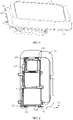
FIG. 1 is a schematic structural diagram of combination of a camera body, a bracket, and a camera decorating part according to an embodiment of this application; -
FIG. 2 is a partial enlarged view of part I inFIG. 1 ; -
FIG. 3 is a schematic structural diagram ofFIG. 1 from another angle of view; -
FIG. 4 is a top view ofFIG. 1 ; -
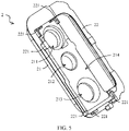
FIG. 5 is a schematic structural diagram of the camera decorating part inFIG. 1 ; -
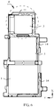
FIG. 6 is a schematic structural diagram of combination of the camera body and the bracket inFIG. 1 ; -
FIG. 7 is a partial enlarged view of part II inFIG. 6 ; -
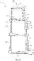
FIG. 8 is a schematic structural diagram of the bracket inFIG. 6 ; -
FIG. 9 is a partial enlarged view of part III inFIG. 8 ; and -
FIG. 10 is a schematic structural diagram of an elastic pad inFIG. 9 . -
- 1-bracket;
- 11-mounting frame;
- 12-separation part;
- 131-first mounting hole;
- 132-second mounting hole;
- 133-third mounting hole;
- 14-elastic pad;
- 141-convex portion;
- 142-concave portion;
- 143-first body portion;
- 15-first side wall;
- 16-second side wall;
- 17-third side wall;
- 18-fourth side wall;
- 2-camera decorating part;
- 21-second body portion;
- 211-fourth mounting hole;
- 212-fifth mounting hole;
- 213-sixth mounting hole;
- 214-mounting groove;
- 22-flange;
221-limiting protrusion;
- 21-second body portion;
- 3-camera; and
- 4-camera lens.
- The accompanying drawings herein are incorporated into the specification and form a part of the specification, show embodiments conforming to this application, and are used together with the specification to explain a principle of this application.
- To make the technical solutions in this application more comprehensible, the following describes the embodiments of this application in detail with reference to the accompanying drawings.
- The terms used in the embodiments of this application are merely for the purpose of illustrating specific embodiments, and are not intended to limit this application. The terms "a", "said", and "the" of singular forms used in the embodiments and the appended claims of this application are also intended to include plural forms, unless otherwise specified in the context clearly.
- It should be understood that the term "and/or" in this specification describes only an association relationship for describing associated objects and represents that three relationships may exist. For example, A and/or B may represent the following three cases: Only A exists, both A and B exist, and only B exists. In addition, the character "/" in this specification generally indicates an "or" relationship between the associated objects.
- It should be noted that, position words such as "above", "below", "left", and "right" described in the embodiments of this application are described from angles shown in the accompanying drawings, and should not be construed as a limitation on the embodiments of this application. Moreover, in the context, it also should be understood that, when it is mentioned that one element is connected "above" or "below" another element, it cannot only be directly connected "above" or "below" the another element, but also be indirectly connected "above" or "below" the another element by using an intermediate element.
- An electronic device includes components such as a housing, a middle frame, a camera, a display, a battery, and a camera decorating part. The battery is mounted on a battery rear cover, and components such as the camera and the display are mounted on the middle frame. Specifically, the camera is mounted by using a bracket, the bracket is mounted in the camera decorating part, and the camera decorating part is mounted on the battery rear cover. A camera lens is mounted on the camera decorating part. The camera corresponds to the camera lens, and can shoot an external environment through the camera lens. In addition, silk printing is usually performed on the camera lens, and a silk printing central hole is formed after the silk printing. The silk printing hole is light-permeable. To improve a shooting effect of the camera and appearance and performance of the electronic device, the camera needs to be concentric with the silk printing central hole. To be specific, during mounting of the camera, a degree of eccentricity between the camera and a camera lens silk screening hole needs to be reduced. To resolve the technical problem, position precision of the camera after the camera is mounted needs to be improved, and a shaking risk of the camera needs to be mitigated.
- The technical problem is resolved in the conventional technology in the following two manners. In a first manner, the camera is fixed to the bracket through dispensing, and it is ensured to the greatest extent that the camera is concentric with the silk printing central hole of the camera lens, and the degree of eccentricity of the camera is reduced. However, in this manner, dispensing needs to be performed by using a dispensing device, and costs are relatively high. In a second manner, the camera is in clearance fit with the bracket, and relative positions of the camera and the bracket can be adjusted by using a clearance between the camera and the bracket, to reduce the degree of eccentricity of the camera. However, the clearance between the camera and the bracket causes relative shaking between the camera and the bracket, resulting in eccentricity of the camera.
- In the embodiments of this application, position precision of a
camera 3 is improved and shaking of thecamera 3 is alleviated mainly by improving a specific structure of abracket 1 of thecamera 3. - Specifically, an embodiment of this application provides a
bracket 1 of acamera 3. As shown inFIG. 8 andFIG. 9 , thebracket 1 includes a mountingframe 11, a mounting hole may be provided in the mountingframe 11, and the mounting hole is configured to mount thecamera 3. The mountingframe 11 is of a structure with specific strength and rigidity. For example, the mountingframe 11 may be made of a material with specific hardness, such as hard rubber or metal, provided that structural strength for mounting thecamera 3 can be satisfied. - In addition, the mounting
frame 11 may specifically include one or more mounting holes. For example, in the embodiment shown inFIG. 8 , the mountingframe 11 includes three mounting holes: a first mountinghole 131, asecond mounting hole 132, and athird mounting hole 133. Therefore, the mountingframe 11 may be configured to mount threecameras 3. Certainly, the mountingframe 11 may alternatively include one, two, or more mounting holes. A quantity of mounting holes is not limited in this application. - In addition, as shown in
FIG. 9 , side walls of the mounting hole include elastic side walls and non-elastic side walls. Specifically, in the embodiment shown inFIG. 9 , a shape of the mounting hole is approximately a rectangle, and the mounting hole includes fourth side walls: afirst side wall 15 and asecond side wall 16 that are disposed opposite to each other, and athird side wall 17 and afourth side wall 18 that are disposed opposite to each other. In the foregoing four side walls, some are elastic side walls, and the others are non-elastic side walls. For example, in thefirst side wall 15 and thesecond side wall 16 that are disposed opposite to each other, thefirst side wall 15 is an elastic side wall, and thesecond side wall 16 is a non-elastic side wall; and in thethird side wall 17 and thefourth side wall 18 that are disposed opposite to each other, thethird side wall 17 is an elastic side wall, and thefourth side wall 18 is a non-elastic side wall. Certainly, in other embodiments, alternatively, thesecond side wall 16 and thefourth side wall 18 may be set to elastic side walls, and thefirst side wall 15 and thethird side wall 17 may be set to non-elastic side walls. - Hardness of the elastic side wall is less than that of the non-elastic side wall, and the elastic side wall and the non-elastic side wall are configured to be in contact with the camera. It should be noted that, the non-elastic side wall mentioned in this application does not mean that the side wall cannot elastically deform, but means that an amount of elastic deformation of the non-elastic side wall is relatively small and is less than an amount of deformation of the elastic side wall.
- In this embodiment, the non-elastic side wall may be formed by the mounting
frame 11, and the mountingframe 11 is of a structure with relatively large hardness, so that the non-elastic side wall is of a structure with relatively large hardness. The elastic side wall may be formed of a rubber material with specific elasticity, so that hardness of the elastic side wall is less than that of the non-elastic side wall. - It should be noted that, the elastic side wall in this embodiment is not necessarily a continuous side wall, and may alternatively be a discontinuous side wall. To be specific, the elastic side wall in this embodiment is a filling region (the filling region is continuous) of elastic materials. The elastic materials may be filled at intervals or continuously in the filling region, and regardless of whether the elastic materials are filled at intervals or continuously, the elastic materials in the filling region form an elastic side wall of a mounting hole. Based on this, the foregoing non-elastic side wall is a non-filling region (the non-filling region is continuous). There is no elastic material in the non-filling region. The non-elastic side wall is a continuous side wall.
- Specifically, as shown in
FIG. 7 , when thecamera 3 is mounted in the mounting hole, thecamera 3 is in interference fit with an elastic side wall of the mounting hole, and can compress the elastic side wall. After fitting ends, the elastic side wall springs back, so that thecamera 3 abuts against a non-elastic side wall (the mounting frame 11) of the mounting hole, thecamera 3 is reliably mounted, and the camera and the bracket form a camera module. - In this embodiment, in a process in which the
camera 3 is mounted in the mounting hole, the elastic side wall can deform after being compressed, so that an area of the mounting hole can be increased, thereby facilitating mounting thecamera 3 in the mounting hole. In addition, the elastic side wall can spring back after thecamera 3 is mounted, so that thecamera 3 abuts against the non-elastic side wall of the mounting hole. This improves the mounting reliability, mitigates a shaking risk of thecamera 3 in the mounting hole, and reduces the degree of eccentricity of thecamera 3, thereby improving a shooting effect of thecamera 3 and the appearance and performance of the electronic device. In addition, during mounting of thecamera 3, dispensing is not required, provided that an elastic structure is added on thebracket 1, so that costs can be reduced. - A magnitude of interference between the elastic side wall and the
camera 3 should not be excessively large. When the magnitude of interference between the elastic side wall and thecamera 3 is excessively large, during mounting of thecamera 3, an interaction force between the elastic side wall and thecamera 3 is relatively large, affecting strength of the elastic side wall and thecamera 3. When the magnitude of interference between the elastic side wall and thecamera 3 is excessively small, after thecamera 3 is mounted, thecamera 3 has a risk of shaking in the mounting hole, resulting in relatively low mounting reliability of thecamera 3. In this embodiment, the magnitude of interference between the elastic side wall and thecamera 3 may be in a range of 0.01 mm to 0.1 mm. In this way, the shaking risk of thecamera 3 can be mitigated, and structural strength of thebracket 1 and thecamera 3 can be improved. - Specifically, the magnitude of interference between the elastic side wall and the
camera 3 may be 0.05 mm, 0.08 mm, or the like. During actual processing, the magnitude of interference between the elastic side wall and thecamera 3 may be set according to structures and sizes of the elastic side wall and thecamera 3. - More specifically, when the elastic side wall is in interference fit with the
camera 3, a larger contact area between the elastic side wall and thecamera 3 indicates a larger stress between the elastic side wall and thecamera 3, as well as higher assembling difficulty, but higher mounting reliability of thecamera 3 in the mounting hole. A smaller contact area between the elastic side wall and thecamera 3 indicates a smaller stress between the elastic side wall and thecamera 3, as well as lower mounting reliability of thecamera 3 in the mounting hole, but lower processing difficulty, and a lower risk of damaging thebracket 1 and thecamera 3 in the mounting process. Therefore, in this embodiment, the contact area between the elastic side wall and thecamera 3 should not be excessively small, and should not be excessively large, either, and may be specifically in a range of 3 mm2 to 6 mm2, for example, 4 mm2 or 5 mm2. During actual processing, the contact area between thecamera 3 and the elastic side wall may be properly determined based on a shape and a size of thecamera 3. - In addition, in the foregoing embodiments, Shore hardness of the elastic side wall of the mounting hole may be in a range of 65 to 75, for example, 68, 70, or 72. A material with the hardness may be specifically flexible rubber or flexible plastic.
- As shown in
FIG. 6 andFIG. 7 , anelastic pad 14 is disposed on the mountingframe 11. Theelastic pad 14 is made of a material with specific elasticity and relatively small hardness. When an external force is applied to theelastic pad 14, theelastic pad 14 can elastically deform, and when the external force is reduced or disappears, theelastic pad 14 can spring back. In this embodiment, theelastic pad 14 is disposed on the mountingframe 11, so that theelastic pad 14 forms the elastic side wall of the mounting hole, and the mountingframe 11 on which theelastic pad 14 is not disposed is used as the non-elastic side wall of the mounting hole. - Specifically, as shown in
FIG. 7 andFIG. 10 , theelastic pad 14 may include a plurality of spacedconvex portions 141. Theconvex portions 141 protrude toward inside of the mounting hole. Theconvex portions 141 form the elastic side wall of the mounting hole. When thecamera 3 is mounted in the mounting hole, thecamera 3 is in interference fit with theconvex portion 141, and a contact area between thecamera 3 and theconvex portion 141 may be in a range of 3 mm2 to 6 mm2. To be specific, a cross-sectional area of theconvex portion 141 may be in a range of 3 mm2 to 6 mm2. In this way, the mounting reliability of thecamera 3 in the mounting hole can be improved, and the mounting difficulty of thecamera 3 can be reduced. - A shape of the
convex portion 141 may be a square, a circle, or another common shape, provided that the contact area between theconvex portion 141 and thecamera 3 is proper. In addition, when the contact area between thecamera 3 and theconvex portion 141 is in a range of 3 mm2 to 6 mm2, and theconvex portion 141 is of a cuboid (or cube) structure, a width of theconvex portion 141 is in a range of 1 mm to 2 mm, and may be specifically 1.5 mm. In the embodiment shown inFIG. 7 , the width of theconvex portion 141 may be a size in a direction Y shown inFIG. 7 . - More specifically, as shown in
FIG. 10 , theelastic pad 14 may include a plurality ofconvex portions 141, and adjacentconvex portions 141 are spaced from each other. A plurality spacedconvex portions 141 form the elastic side wall of the mounting hole. When thecamera 3 is mounted in the mounting hole, thecamera 3 is in interference fit with eachconvex portion 141, and a contact area between eachconvex portion 141 and acamera 3 may be in a range of 3 mm2 to 6 mm2. To be specific, the cross-sectional area of theconvex portion 141 may be in a range of 3 mm2 to 6 mm2. A larger quantity ofconvex portions 141 of theelastic pad 14 indicates a larger contact area between theelastic pad 14 and eachcamera 3, and higher reliability of connection between theelastic pad 14 and thecamera 3. In this way, the mounting reliability of thecamera 3 in the mounting hole can be improved, and the mounting difficulty of thecamera 3 can be reduced. - The elastic side wall of the mounting hole is of a discontinuous structure. To be specific, a plurality of spaced
convex portions 141 form the elastic side wall, and a region in which theconvex portions 141 are located is a filling region of the side wall of the mounting hole. - In this embodiment, a
concave portion 142 is formed between adjacentconvex portions 141. When thecamera 3 is mounted in the mounting hole, theconvex portions 141 can deform toward theconcave portions 142. In other words, settings of theconcave portions 142 can provide space for deformation of theconvex portions 141. This facilitates compression and deformation of theconvex portions 141, thereby further reducing the mounting difficulty of thecamera 3. In addition, theconcave portions 142 can further alleviate stress concentration between theconvex portions 141 and thecamera 3, to mitigate the risk of damaging thebracket 1 and thecamera 3 in the mounting process. - In a possible design, as shown in
FIG. 7 andFIG. 10 , theelastic pad 14 includes afirst body portion 143 and theconvex portions 141. Thefirst body portion 143 and theconvex portions 141 are fixedly connected or integrally formed. Thefirst body portion 143 is connected to the mountingframe 11, and theconvex portions 141 protrude relative to thefirst body portion 143. - In this embodiment, the
convex portions 141 in interference fit with thecamera 3 are connected into an integrated structure by using thefirst body portion 143, so that theelastic pad 14 is of an integrated structure. In addition, theconvex portions 141 are connected to the mountingframe 11 by using thefirst body portion 143. In this embodiment, theelastic pad 14 of the integrated structure has an advantage of processing convenience, and can improve reliability of connection between theconvex portions 141 and the mountingframe 11, thereby improving the mounting reliability of thecamera 3. - In another specific embodiment, the
elastic pad 14 may alternatively include only a plurality ofconvex portions 141, and theconvex portions 141 are of separated structures. When theconvex portions 141 are connected to the mountingframe 11, theelastic pad 141 is formed. In this embodiment, when theelastic pad 14 of a separated structure is used, usage of elastic materials can be reduced, to help reduce a weight and a size of the electronic device. - In a possible design, the
elastic pad 14 includes a flexible rubber material. Flexible rubber is a material formed through plastic injection molding, and has a feature of relatively small hardness. In addition, the flexible rubber can spring back after forced deformation. In addition, the mountingframe 11 may include a metal or hard plastic material. Hard plastic is a material formed through plastic injection molding, and has a feature of relatively high hardness. In addition, hardness of the hard plastic is greater than that of the flexible rubber, and an elastic coefficient of the hard plastic is less than that of the flexible rubber. - In this embodiment, the
elastic pad 14 and the mountingframe 11 may be integrally formed through double-shot molding. To be specific, the bracket 1 (including the mountingframe 11 and the elastic pad 14) may be of an integrally formed structure. The double-shot molding means inject-molding two different materials into a same set of mold, to implement a forming process in which a part formed through injection molding is formed of two materials. The two materials may be materials with different colors or different hardness. - Therefore, the flexible rubber and metal may be formed into the
bracket 1 through double-shot molding, or the hard plastic and the metal may be formed into thebracket 1 through double-shot molding. - In a specific embodiment, as shown in
FIG. 7 , the mounting hole of the mountingframe 11 is of a square structure. To be specific, side walls of the mounting hole include thefirst side wall 15 and thesecond side wall 16 that are disposed opposite to each other, and thethird side wall 17 and thefourth side wall 18 that are disposed opposite to each other. In addition, thefirst side wall 15 is adjacent to thethird side wall 17 and thefourth side wall 18, and the four side walls define a mounting hole of the mountingframe 11 through enclosure. - At least one part of the
first side wall 15 is an elastic side wall. To be specific, the foregoing elastic materials (for example, the elastic pad 14) may be filled in at least one part of thefirst side wall 15. When the elastic materials are filled in one part of thefirst side wall 15, thefirst side wall 15 includes an elastic side wall and a non-elastic side wall. Correspondingly, thesecond side wall 16 disposed opposite to thefirst side wall 15 is a non-elastic side wall. To be specific, no elastic materials (for example, the elastic pad 14) are filled in thesecond side wall 16. It should be noted that, at least one part of one of thefirst side wall 15 and thesecond side wall 16 may be an elastic side wall, and the other side wall is a non-elastic side wall. To be specific, alternatively, at least one part of thesecond side wall 16 is an elastic side wall, and thefirst side wall 15 is a non-elastic side wall. - Similarly, at least one part of the
third side wall 17 is an elastic side wall. To be specific, the foregoing elastic materials (for example, the elastic pad 14) may be filled in at least one part of thethird side wall 17. When the elastic materials are filled in one part of thethird side wall 17, the third side wall includes an elastic side wall and a non-elastic side wall. Correspondingly, thefourth side wall 18 disposed opposite to thethird side wall 17 is a non-elastic side wall. To be specific, no elastic materials (for example, the elastic pad 14) are filled in thefourth side wall 18. It should be noted that, at least one part of one of thethird side wall 17 and thefourth side wall 18 may be an elastic side wall, and the other side wall is a non-elastic side wall. To be specific, alternatively, at least one part of thefourth side wall 18 is an elastic side wall, and thethird side wall 17 is a non-elastic side wall. - In this embodiment, elastic side walls are located on two adjacent side walls of the square mounting hole. To be specific, the elastic side walls may be disposed on the
first side wall 15 and the third side wall 17 (as shown inFIG. 9 ), or thefirst side wall 15 and thefourth side wall 18, or thesecond side wall 16 and thethird side wall 17, or thesecond side wall 16 and thefourth side wall 18. In addition, using an example in which thefirst side wall 15 includes an elastic side wall, theelastic pad 14 disposed on thefirst side wall 15 may be of a continuous-shaped structure or a discontinuous-shaped structure. - Using the embodiment shown in
FIG. 9 as an example, in a process in which thecamera 3 is mounted in the mounting hole, under an effect of an external force, thecamera 3 is in interference fit with the elastic materials, and the elastic materials (for example, the elastic pad) disposed on thefirst side wall 15 and thethird side wall 17 are compressed to deform, to facilitate placing thecamera 3 into the mounting hole. When the external force is reduced or disappears, under an effect of resilience of the elastic materials, a position of thecamera 3 in the mounting hole changes. To be specific, thecamera 3 has a tendency of moving toward thesecond side wall 16 and thefourth side wall 18, so that thecamera 3 abuts against thesecond side wall 16 and the fourthsecond side wall 18, or thecamera 3 is in contact with thesecond side wall 16 and thefourth side wall 18 without a clearance. To be specific, an interaction force between thecamera 3 and thesecond side wall 16 and thefourth side wall 18 is relatively small. In this way, thecamera 3 is mounted. In addition, after thecamera 3 is mounted, thecamera 3 may still be in interference fit with the elastic side walls. This improves the mounting reliability of thecamera 3, and reduces the degree of eccentricity of thecamera 3. - Specifically, as shown in
FIG. 9 andFIG. 10 ,elastic pads 14 disposed on adjacent side walls are connected to each other or integrally formed, forming a structure shown inFIG. 10 . To be specific, theelastic pad 14 is approximately L-shaped, so that areas of elastic side walls can be increased. During processing, theelastic pad 14 may be flexible rubber of an L-shaped structure, and the flexible rubber and hard plastic or the flexible rubber and metal are processed by using a double-shot molding process, to form thebracket 1 shown inFIG. 8 . - Certainly,
elastic pads 14 on adjacent side walls may alternatively be of separated structures. In other words, twoelastic pads 14 disposed on adjacent side walls are separated from each other. In this case, usage of elastic materials can be reduced. - According to another aspect, in the embodiment shown in
FIG. 8 , aseparation part 12 may be disposed in the mountingframe 11. For example, twoseparation parts 12 may be disposed, to divide the mountingframe 11 into three mounting holes: a first mountinghole 131, asecond mounting hole 132, and athird mounting hole 133. The three mounting holes can all be configured to mountcameras 3. - Based on this, because the
separation part 12 is side walls of two adjacent mounting holes, theseparation part 12 may be used as elastic side walls or non-elastic side walls of the adjacent mounting holes. UsingFIG. 8 as an example, in theseparation part 12 between the first mountinghole 131 and thesecond mounting hole 132, a side facing toward inside of the first mountinghole 131 is a non-elastic side wall, and a side facing toward inside of thesecond mounting hole 132 is an elastic side wall. Therefore, whencameras 3 are mounted in the first mountinghole 131 and thesecond mounting hole 132, onecamera 3 is in interference fit with theseparation part 12, and theother camera 3 abuts against theseparation part 12. In other words, an acting force acting on theseparation part 12 is not excessively large. This improves structural strength of theseparation part 12. - In the
separation part 12 between thesecond mounting hole 132 and the third mountinghole 133, both a side facing toward thesecond mounting hole 132 and a side facing toward the third mountinghole 133 may be non-elastic side walls. Therefore, whencameras 3 are mounted in thesecond mounting hole 132 and the third mountinghole 133, the twocameras 3 both abut against theseparation part 12. Therefore, an acting force acting on theseparation part 12 is relatively small, thereby improving structural strength of thesecond separation part 12. - In addition, when
cameras 3 are mounted in adjacent mounting holes, the twocameras 3 may both be in interference fit with theseparation part 12 between the two mounting holes. To be specific, two sides of theseparation part 12 between the adjacent mounting holes may both be used as elastic side walls. In this case, an acting force acting on thesecond separation part 12 is relatively large. - In another possible design, the mounting hole of the
bracket 1 may alternatively be of a circular structure. In this case, a base of thecamera 3 is of a circular structure matching the mounting hole. Therefore, in the mounting hole, both an elastic side wall and a non-elastic side wall may be of arc-shaped structures. - In addition, in this embodiment, a central angle of an elastic side wall may be the same as or different from that of a non-elastic side wall.
- In the foregoing embodiments, the electronic device further includes components such as a
camera decorating part 2, a middle frame, and a battery cover. Thebracket 1 can be mounted in thecamera decorating part 2. Specifically, as shown inFIG. 5 , thecamera decorating part 2 includes asecond body portion 21 and aflange 22. Theflange 22 is disposed on a periphery of thesecond body portion 21, and a mountinggroove 214 is provided in thesecond body portion 21. Thebracket 1 is mounted in the mountinggroove 214. A fourth mountinghole 211, a fifth mountinghole 212, and a sixth mountinghole 213 are provided in a bottom wall of the mountinggroove 214. The foregoing three mounting holes respectively correspond to threecameras 3. When thebracket 1 is mounted in thecamera decorating part 2, the threecameras 3 are respectively located in the fourth mountinghole 211, the fifth mountinghole 212, and the sixth mountinghole 213. - As shown in
FIG. 3 , acamera lens 4 is disposed on a back surface of thecamera decorating part 2, and thecameras 3 correspond to thecamera lens 4 respectively through the fourth mountinghole 211, the fifth mountinghole 212, and the sixth mountinghole 213. In this way, an external environment can be shot through thecamera lens 4, and a user can observe thecameras 3 through thecamera lens 4. - One
camera lens 4 may be disposed on thecamera decorating part 2, and thecamera lens 4 corresponds to the cameras 3 (for example, when threecameras 3 are included, thecamera lens 4 corresponds to the three cameras 3). Alternatively, a quantity ofcamera lenses 4 in thecamera decorating part 2 may be the same as that of cameras 3 (for example, when threecameras 3 are included, thecamera decorating part 2 includes three camera lenses 4), and thecamera lenses 4 are in one-to-one correspondence to thecameras 3. - Moreover, to improve the shooting effect and the appearance and performance of the
camera 3, a degree of concentricity between eachcamera 3 and a silk printing central hole in thecamera lens 4 needs to be improved. To be specific, mounting precision of thecamera 3 needs to be improved, and shaking of thecamera 3 in thebracket 1 needs to be alleviated. - To resolve the technical problem, an elastic material is added on a side wall of the mounting hole of the
bracket 1, to improve position precision of thecamera 3 in the mounting hole of thebracket 1, and alleviate shaking of thecamera 3 in the mounting hole. In addition, because thebracket 1 is mounted in thecamera decorating part 2, position precision of thebracket 1 in thecamera decorating part 2 further needs to be improved, and a shaking risk of thebracket 1 in the mountinggroove 214 of thecamera decorating part 2 needs to be mitigated. - Specifically, as shown in
FIG. 1, FIG. 2 , andFIG. 5 , limitingprotrusions 221 are disposed on theflange 22 of thecamera decorating part 2. Each limitingprotrusion 221 abuts against thebracket 1, to alleviate shaking of thebracket 1 in thecamera decorating part 2, thereby improving position precision of thebracket 1. - Specifically, limiting
protrusions 221 are disposed on both two ends of theflange 22 along a length direction X of thebracket 1, and the limitingprotrusions 221 located on the two ends along the length direction X can limit shaking of thebracket 1 along the length direction X. In addition, limitingprotrusions 221 are disposed on both two ends of theflange 22 along a width direction Y of thebracket 1, and the limitingprotrusions 221 located on the two ends along the width direction Y can limit shaking of thebracket 1 along the width direction Y, thereby mitigating a shaking risk of thebracket 1 in thecamera decorating part 2. - During mounting of the
camera 3 in the embodiments of this application, thecamera 3 is first mounted on the middle frame, and then thecamera 3 is connected to the bracket (thecamera 3 is in interference fit with an elastic side wall of the mounting hole, and abuts against a non-elastic side wall), to form a camera module. Alternatively, thecamera 3 may be first mounted on thebracket 1, to form the camera module, and then the camera module is mounted on the middle frame. Then, thebracket 1 is mounted in the mountinggroove 214 of thecamera decorating part 2, and is limited by using the limitingprotrusions 221. Thecamera lens 4 is mounted on thecamera decorating part 2, so that thecamera 3 is concentric with the silk printing central hole of thecamera lens 4. When the electronic device includes a plurality of cameras 3 (for example, three cameras 3), thecamera lens 4 may be correspondingly provided with a plurality of silk printing central holes (for example, three silk printing central holes), and thecameras 3 are enabled to correspond to the corresponding silk printing central holes. Thecamera decorating part 2 is mounted on the battery cover of the electronic device. - In conclusion, the
bracket 1 provided in the embodiments of this application can effectively improve the position precision of thecamera 3, and mitigate the shaking risk of thecamera 3, to reduce the degree of eccentricity between thecamera 3 and thecamera lens 4, improve the shooting effect of thecamera 3, and improve the appearance and performance of the electronic device. - The foregoing descriptions are merely preferred embodiments of this application, but are not intended to limit this application. For a person skilled in the art, various changes and variations may be made in this application. Any modification, equivalent replacement, or improvement made without departing from the spirit and principle of this application shall fall within the protection scope of this application.
Claims (14)
- A camera bracket, wherein the bracket comprises a mounting frame, a mounting hole is provided in the mounting frame, and the mounting hole is configured to mount a camera; and
side walls of the mounting hole comprise an elastic side wall and a non-elastic side wall, hardness of the elastic side wall is less than that of the non-elastic side wall, and the elastic side wall and the non-elastic side wall are configured to be in contact with the camera. - The bracket according to claim 1, wherein an elastic material of the elastic side wall is of an integrated structure, or the elastic material of the elastic side wall is of a separated structure.
- The bracket according to claim 1, wherein an elastic pad is disposed on the mounting frame, the elastic pad comprises convex portions, the convex portions protrude toward inside of the mounting hole, and the convex portions form the elastic side wall.
- The bracket according to claim 3, wherein the elastic pad comprises a plurality of the convex portions that are spaced.
- The bracket according to claim 3, wherein the elastic pad further comprises a first body portion, the first body portion is connected to the mounting frame, and the convex portions protrude relative to the first body portion.
- The bracket according to claim 3, wherein the elastic pad comprises flexible rubber, the mounting frame comprises metal or hard plastic, and the elastic pad and the mounting frame are integrally formed or fixedly connected.
- The bracket according to any one of claims 1 to 6, wherein the mounting hole is of a square structure, and the side walls of the mounting hole comprise a first side wall and a second side wall that are disposed opposite to each other, and a third side wall and a fourth side wall that are disposed opposite to each other; and
at least one part of one of the first side wall and the second side wall is the elastic side wall, and the other side wall is the non-elastic side wall; and at least one part of one of the third side wall and the fourth side wall is the elastic side wall, and the other side wall is the non-elastic side wall. - The bracket according to any one of claims 1 to 6, wherein the mounting hole is of a circular structure, the elastic side wall is of an arc-shaped structure, and the non-elastic side wall is of an arc-shaped structure.
- The bracket according to any one of claims 1 to 6, wherein Shore hardness of the elastic material of the elastic side wall is in a range of 65 to 75.
- An electronic device, wherein the electronic device comprises:a camera;a bracket, wherein the camera is mounted on the bracket, and the bracket is the bracket according to any one of claims 1 to 9; anda camera decorating part, wherein the bracket is mounted in the camera decorating part.
- The electronic device according to claim 10, wherein the camera is in interference fit with the elastic side wall, and a magnitude of interference between the camera and the elastic side wall is in a range of 0.01 mm to 0.1 mm.
- The electronic device according to claim 10 or 11, wherein the camera abuts against the non-elastic side wall.
- The electronic device according to claim 10 or 11, wherein a contact area between the elastic side wall and the camera is in a range of 3 mm2 to 6 mm2.
- The electronic device according to claim 10 or 11, wherein the camera decorating part comprises an accommodating groove, and the bracket is located in the accommodating groove;a plurality of limiting protrusions are also provided on the camera decorating part, a part of the limiting protrusions are located on two ends along a length direction of the bracket, and a part of the limiting protrusions are located on two ends along a width direction of the bracket; andthe limiting protrusions abut against the bracket.
Applications Claiming Priority (2)
| Application Number | Priority Date | Filing Date | Title |
|---|---|---|---|
| CN201911166970.8A CN110913104B (en) | 2019-11-25 | 2019-11-25 | Camera support and electronic equipment |
| PCT/CN2020/128006 WO2021104016A1 (en) | 2019-11-25 | 2020-11-11 | Support for camera and electronic apparatus |
Publications (2)
| Publication Number | Publication Date |
|---|---|
| EP4013029A1 true EP4013029A1 (en) | 2022-06-15 |
| EP4013029A4 EP4013029A4 (en) | 2022-10-12 |
Family
ID=69819341
Family Applications (1)
| Application Number | Title | Priority Date | Filing Date |
|---|---|---|---|
| EP20894303.5A Ceased EP4013029A4 (en) | 2019-11-25 | 2020-11-11 | Support for camera and electronic apparatus |
Country Status (5)
| Country | Link |
|---|---|
| US (1) | US12155917B2 (en) |
| EP (1) | EP4013029A4 (en) |
| CN (2) | CN115473989B (en) |
| DE (1) | DE202020006058U1 (en) |
| WO (1) | WO2021104016A1 (en) |
Families Citing this family (6)
| Publication number | Priority date | Publication date | Assignee | Title |
|---|---|---|---|---|
| CN115473989B (en) * | 2019-11-25 | 2024-03-08 | 荣耀终端有限公司 | Camera mounts and electronics |
| CN111629092A (en) * | 2020-05-29 | 2020-09-04 | 维沃移动通信有限公司 | Decorative Rings and Electronics |
| CN112261259B (en) * | 2020-10-20 | 2023-02-17 | 北京字节跳动网络技术有限公司 | Camera module support, terminal and camera module mounting method |
| CN115767246B (en) * | 2021-09-02 | 2024-12-31 | 广州视源电子科技股份有限公司 | Camera mounting method and mounting structure |
| CN219514447U (en) * | 2023-01-18 | 2023-08-11 | 荣耀终端有限公司 | Socket frame, middle frame component and electronic equipment |
| US12321083B2 (en) | 2023-10-17 | 2025-06-03 | Google Llc | Camera alignment |
Family Cites Families (18)
| Publication number | Priority date | Publication date | Assignee | Title |
|---|---|---|---|---|
| JP2008113066A (en) | 2006-10-27 | 2008-05-15 | Sony Corp | Imaging device |
| CN201029132Y (en) * | 2007-03-09 | 2008-02-27 | 富士康(昆山)电脑接插件有限公司 | electrical connector |
| TW201134060A (en) * | 2010-03-25 | 2011-10-01 | Hon Hai Prec Ind Co Ltd | Voice coil motor actuator and camera module |
| JP2012048008A (en) * | 2010-08-27 | 2012-03-08 | Kyocera Corp | Imaging device |
| TWI493838B (en) * | 2011-06-03 | 2015-07-21 | Hon Hai Prec Ind Co Ltd | Voice coil motor and image capturing module using same |
| TWI582482B (en) | 2015-11-20 | 2017-05-11 | 晶睿通訊股份有限公司 | Lens fixing mechanism and image capturing device thereof |
| CN205123864U (en) * | 2015-11-20 | 2016-03-30 | 乐视移动智能信息技术(北京)有限公司 | Camera packaging part and electronic product encapsulating shell |
| CN106850882B (en) * | 2016-12-20 | 2020-03-24 | Oppo广东移动通信有限公司 | Bracket component and mobile terminal |
| CN206650701U (en) * | 2017-03-16 | 2017-11-17 | 广东欧珀移动通信有限公司 | Housing unit and there is its terminal |
| CN206738860U (en) | 2017-05-16 | 2017-12-12 | 湖南中铁五新重工有限公司 | A kind of camera mounting support |
| CN207124685U (en) | 2017-09-04 | 2018-03-20 | 上海青橙实业有限公司 | Camera module is grounded erecting device and electronic equipment |
| CN110035202A (en) | 2018-01-12 | 2019-07-19 | 深圳富泰宏精密工业有限公司 | Housing unit, electronic building brick mould group and the electronic device with electronic building brick mould group |
| CN108965669A (en) | 2018-07-26 | 2018-12-07 | 维沃移动通信有限公司 | A mobile terminal and camera module of the mobile terminal |
| CN109257531B (en) * | 2018-11-09 | 2023-11-28 | 昆山丘钛微电子科技有限公司 | Camera module and production method and terminal |
| CN209089012U (en) | 2018-12-12 | 2019-07-09 | 北京小米移动软件有限公司 | Camera Modules and Electronic Equipment |
| CN110278364A (en) * | 2019-07-18 | 2019-09-24 | Oppo广东移动通信有限公司 | Camera Modules and Electronics |
| CN110278363B (en) * | 2019-07-18 | 2021-02-23 | Oppo广东移动通信有限公司 | Camera module and electronic device |
| CN115473989B (en) | 2019-11-25 | 2024-03-08 | 荣耀终端有限公司 | Camera mounts and electronics |
-
2019
- 2019-11-25 CN CN202210946102.7A patent/CN115473989B/en active Active
- 2019-11-25 CN CN201911166970.8A patent/CN110913104B/en active Active
-
2020
- 2020-11-11 WO PCT/CN2020/128006 patent/WO2021104016A1/en not_active Ceased
- 2020-11-11 US US17/778,451 patent/US12155917B2/en active Active
- 2020-11-11 DE DE202020006058.5U patent/DE202020006058U1/en active Active
- 2020-11-11 EP EP20894303.5A patent/EP4013029A4/en not_active Ceased
Also Published As
| Publication number | Publication date |
|---|---|
| WO2021104016A1 (en) | 2021-06-03 |
| CN110913104A (en) | 2020-03-24 |
| CN115473989A (en) | 2022-12-13 |
| CN115473989B (en) | 2024-03-08 |
| CN110913104B (en) | 2022-09-06 |
| US12155917B2 (en) | 2024-11-26 |
| EP4013029A4 (en) | 2022-10-12 |
| US20220407990A1 (en) | 2022-12-22 |
| DE202020006058U1 (en) | 2024-08-21 |
Similar Documents
| Publication | Publication Date | Title |
|---|---|---|
| US12155917B2 (en) | Camera bracket and electronic device | |
| US7267313B2 (en) | Retaining device for the floating mounting of a flat screen and electronic display device comprising a flat screen and a retaining device | |
| EP3432052B1 (en) | Virtual reality glasses | |
| EP4020513B1 (en) | Electronic device | |
| US20170012516A1 (en) | Vibrating motor | |
| EP3072412A1 (en) | A case for a mobile electronic device | |
| CN110248066B (en) | Camera module and terminal equipment | |
| TW201408061A (en) | Camera module assembly carrier | |
| JP2014220500A (en) | Case for electronic device | |
| KR20130077836A (en) | Set-top box having rubber feet | |
| HK40069829A (en) | Support for camera and electronic apparatus | |
| US20180062689A1 (en) | Mobile terminal and rear housing for mobile terminal | |
| CN213562228U (en) | Electronic equipment screen assembling clamp | |
| RU2691842C1 (en) | Data supply line for virtual reality glasses | |
| CN112822319B (en) | Display screen anti-fall structure and electronic device having the same | |
| CN113890912A (en) | Electronic equipment | |
| KR20250023269A (en) | Reticle Pod Provided with Reticle Support for Absorbing Downward Pressure | |
| CN214480887U (en) | camera module | |
| US10804046B2 (en) | Key structure and electronic apparatus | |
| CN215835421U (en) | Electronic equipment | |
| KR200476557Y1 (en) | Smart phon protection case having cushioning and sticking function | |
| CN215871508U (en) | Protective shell | |
| US20040135920A1 (en) | Camera case structure for a mobile communication device | |
| CN207166573U (en) | The scratch resistant containment vessel of anticollision antidetonation | |
| CN216046432U (en) | Mounting mechanism for screen |
Legal Events
| Date | Code | Title | Description |
|---|---|---|---|
| STAA | Information on the status of an ep patent application or granted ep patent |
Free format text: STATUS: THE INTERNATIONAL PUBLICATION HAS BEEN MADE |
|
| PUAI | Public reference made under article 153(3) epc to a published international application that has entered the european phase |
Free format text: ORIGINAL CODE: 0009012 |
|
| STAA | Information on the status of an ep patent application or granted ep patent |
Free format text: STATUS: REQUEST FOR EXAMINATION WAS MADE |
|
| 17P | Request for examination filed |
Effective date: 20220309 |
|
| AK | Designated contracting states |
Kind code of ref document: A1 Designated state(s): AL AT BE BG CH CY CZ DE DK EE ES FI FR GB GR HR HU IE IS IT LI LT LU LV MC MK MT NL NO PL PT RO RS SE SI SK SM TR |
|
| A4 | Supplementary search report drawn up and despatched |
Effective date: 20220912 |
|
| RIC1 | Information provided on ipc code assigned before grant |
Ipc: H04M 1/02 20060101ALI20220906BHEP Ipc: H04N 5/225 20060101AFI20220906BHEP |
|
| REG | Reference to a national code |
Ref country code: HK Ref legal event code: DE Ref document number: 40069829 Country of ref document: HK |
|
| DAV | Request for validation of the european patent (deleted) | ||
| DAX | Request for extension of the european patent (deleted) | ||
| STAA | Information on the status of an ep patent application or granted ep patent |
Free format text: STATUS: EXAMINATION IS IN PROGRESS |
|
| 17Q | First examination report despatched |
Effective date: 20230405 |
|
| REG | Reference to a national code |
Ref country code: DE Ref legal event code: R003 |
|
| STAA | Information on the status of an ep patent application or granted ep patent |
Free format text: STATUS: THE APPLICATION HAS BEEN REFUSED |
|
| 18R | Application refused |
Effective date: 20240319 |