EP4013023A1 - Network sharing method and related device - Google Patents
Network sharing method and related device Download PDFInfo
- Publication number
- EP4013023A1 EP4013023A1 EP20856266.0A EP20856266A EP4013023A1 EP 4013023 A1 EP4013023 A1 EP 4013023A1 EP 20856266 A EP20856266 A EP 20856266A EP 4013023 A1 EP4013023 A1 EP 4013023A1
- Authority
- EP
- European Patent Office
- Prior art keywords
- network
- wifi
- electronic device
- numerical value
- target
- Prior art date
- Legal status (The legal status is an assumption and is not a legal conclusion. Google has not performed a legal analysis and makes no representation as to the accuracy of the status listed.)
- Granted
Links
Images



Classifications
-
- H—ELECTRICITY
- H04—ELECTRIC COMMUNICATION TECHNIQUE
- H04W—WIRELESS COMMUNICATION NETWORKS
- H04W76/00—Connection management
- H04W76/10—Connection setup
- H04W76/15—Setup of multiple wireless link connections
-
- H—ELECTRICITY
- H04—ELECTRIC COMMUNICATION TECHNIQUE
- H04M—TELEPHONIC COMMUNICATION
- H04M1/00—Substation equipment, e.g. for use by subscribers
- H04M1/72—Mobile telephones; Cordless telephones, i.e. devices for establishing wireless links to base stations without route selection
- H04M1/724—User interfaces specially adapted for cordless or mobile telephones
- H04M1/72403—User interfaces specially adapted for cordless or mobile telephones with means for local support of applications that increase the functionality
- H04M1/72409—User interfaces specially adapted for cordless or mobile telephones with means for local support of applications that increase the functionality by interfacing with external accessories
-
- H—ELECTRICITY
- H04—ELECTRIC COMMUNICATION TECHNIQUE
- H04M—TELEPHONIC COMMUNICATION
- H04M1/00—Substation equipment, e.g. for use by subscribers
- H04M1/72—Mobile telephones; Cordless telephones, i.e. devices for establishing wireless links to base stations without route selection
- H04M1/724—User interfaces specially adapted for cordless or mobile telephones
- H04M1/72403—User interfaces specially adapted for cordless or mobile telephones with means for local support of applications that increase the functionality
- H04M1/72409—User interfaces specially adapted for cordless or mobile telephones with means for local support of applications that increase the functionality by interfacing with external accessories
- H04M1/72412—User interfaces specially adapted for cordless or mobile telephones with means for local support of applications that increase the functionality by interfacing with external accessories using two-way short-range wireless interfaces
-
- H—ELECTRICITY
- H04—ELECTRIC COMMUNICATION TECHNIQUE
- H04W—WIRELESS COMMUNICATION NETWORKS
- H04W76/00—Connection management
- H04W76/30—Connection release
-
- H—ELECTRICITY
- H04—ELECTRIC COMMUNICATION TECHNIQUE
- H04M—TELEPHONIC COMMUNICATION
- H04M1/00—Substation equipment, e.g. for use by subscribers
- H04M1/72—Mobile telephones; Cordless telephones, i.e. devices for establishing wireless links to base stations without route selection
- H04M1/724—User interfaces specially adapted for cordless or mobile telephones
- H04M1/72448—User interfaces specially adapted for cordless or mobile telephones with means for adapting the functionality of the device according to specific conditions
-
- H—ELECTRICITY
- H04—ELECTRIC COMMUNICATION TECHNIQUE
- H04M—TELEPHONIC COMMUNICATION
- H04M2250/00—Details of telephonic subscriber devices
- H04M2250/06—Details of telephonic subscriber devices including a wireless LAN interface
-
- H—ELECTRICITY
- H04—ELECTRIC COMMUNICATION TECHNIQUE
- H04W—WIRELESS COMMUNICATION NETWORKS
- H04W76/00—Connection management
- H04W76/30—Connection release
- H04W76/34—Selective release of ongoing connections
-
- H—ELECTRICITY
- H04—ELECTRIC COMMUNICATION TECHNIQUE
- H04W—WIRELESS COMMUNICATION NETWORKS
- H04W84/00—Network topologies
- H04W84/02—Hierarchically pre-organised networks, e.g. paging networks, cellular networks, WLAN [Wireless Local Area Network] or WLL [Wireless Local Loop]
- H04W84/10—Small scale networks; Flat hierarchical networks
- H04W84/12—WLAN [Wireless Local Area Networks]
-
- H—ELECTRICITY
- H04—ELECTRIC COMMUNICATION TECHNIQUE
- H04W—WIRELESS COMMUNICATION NETWORKS
- H04W92/00—Interfaces specially adapted for wireless communication networks
- H04W92/04—Interfaces between hierarchically different network devices
- H04W92/10—Interfaces between hierarchically different network devices between terminal device and access point, i.e. wireless air interface
Definitions
- This disclosure relates to the field of electronics technology, in particular to a method for network sharing and related devices.
- the electronic device can support a WIFI function and a network sharing function.
- the WIFI function is used for WIFI network access.
- the network sharing function is used for other devices to access the electronic device to realize network sharing.
- Implementations of the present disclosure provide a method for network sharing and related devices, which can achieve coexistence of a Wi-Fi function and a network sharing function and improve performance of an electronic device.
- implementations of the present disclosure provide a method for network sharing, which is applied to an electronic device with a WIFI module.
- the method includes the following.
- the electronic device Upon detecting a network-sharing enablement request, whether the electronic device has created two first network interfaces through the WIFI module is determined, the first network interfaces being used for WIFI network access. One of the two first network interfaces is released on condition that the electronic device has created the two first network interfaces through the WIFI module. Network sharing is enabled once the one of the two first network interfaces is successfully released.
- implementations of the present disclosure provide a device for network sharing, which is applied to an electronic device with a WIFI module.
- the device includes a first determining unit, an interface control unit, and a network control unit.
- the first determining unit is configured to determine whether the electronic device has created two first network interfaces through the WIFI module upon detecting a network-sharing enablement request, the first network interfaces being used for WIFI network access.
- the interface control unit is configured to release one of the two first network interfaces on condition that the electronic device has created the two first network interfaces through the WIFI module.
- the network control unit is configured to enable network sharing once the one of the two first network interfaces is successfully released.
- implementations of the present disclosure provide an electronic device.
- the electronic device includes a processor, a memory, a communication interface, and one or more programs.
- the one or more programs are stored in the memory and configured to be executed by the processor, and the programs include instructions for executing operations of the method described in the first aspect of the implementations of the present disclosure.
- implementations of the present disclosure provide a computer-readable storage medium.
- the computer-readable storage medium stores a computer program for Electronic Data Interchange (EDI).
- EDI Electronic Data Interchange
- the computer program causes a computer to perform part or all of operations of the method described in the first aspect of the implementations of the present disclosure.
- implementations of the present disclosure provide a computer program product.
- the computer program product includes a non-transitory computer readable storage medium storing a computer program.
- the computer program is operable to cause a computer to perform part or all of operations of the method described in the first aspect of the implementations of the present disclosure.
- the computer program product may be a software installation package.
- FIG. 1A illustrates a communication system provided in implementations of the disclosure
- the communication system includes multiple electronic devices and multiple wireless Access Points (AP), and an AP is an access point of a WIFI network.
- the electronic device supports a dual-WIFI function, that is, the electronic device can access two WIFI networks.
- the electronic device can access WIFI network 1 through AP1 and WIFI network 2 through AP2.
- the electronic device supports coexistence of a WIFI function and a network sharing function.
- electronic device 1 accesses WIFI network 1 through API
- electronic device 1 creates a WIFI network
- electronic device 2 accesses the WIFI network created by the electronic device 1 through the electronic device 1.
- Forms and numbers of the electronic devices and APs illustrated in FIG. 1A are by way of example only, and do not present a limitation on implementations of the disclosure.
- the electronic device can include various handheld devices, vehicle-mounted devices, wearable devices, computing devices with a wireless communication function or other processing devices connected to a wireless modem, as well as various forms of User Equipment (UE), Mobile Station (MS), terminal device and the like.
- UE User Equipment
- MS Mobile Station
- FIG. 1B is a schematic structural diagram of an electronic device according to implementations of the present disclosure.
- the electronic device includes a processor, a memory, a signal processor, a transceiver, a display screen, a speaker, a microphone, a Random Access Memory (RAM), a camera, a sensor, a WIFI module, and the like.
- the memory, the signal processor, the display screen, the speaker, the microphone, the RAM, the camera, the sensor, and the WIFI module are connected with the processor, and the transceiver is connected with the signal processor.
- the display screen can be a liquid crystal display (LCD), an organic light-emitting diode (OLED) or inorganic light-emitting diode, an active matrix organic light emitting diode (AMOLED), etc.
- LCD liquid crystal display
- OLED organic light-emitting diode
- AMOLED active matrix organic light emitting diode
- the camera can be an ordinary camera or an infrared camera, which is not limited herein.
- the camera can be a front camera or a rear camera, which is not limited herein.
- the sensor includes at least one of the following: a light sensor, a gyroscope, an infrared proximity sensor, a fingerprint sensor, a pressure sensor, etc.
- the light sensor also known as an ambient light sensor, is configured to detect brightness of ambient light.
- the light sensor may include a photosensitive element and an analog-to-digital converter.
- the photosensitive element is configured to convert a collected optical signal into an electrical signal
- the analog-to-digital converter is configured to convert the electrical signal into a digital signal.
- the light sensor can also include a signal amplifier, which can amplify the electrical signal converted by the photosensitive element and then output it to the analog-to-digital converter.
- the photosensitive element may include at least one of a photodiode, a phototransistor, a photoresistor, and a silicon photocell.
- the processor is a control center of the electronic device, which connects all parts of the whole electronic device using various interfaces and lines. By running or executing software programs and/or modules stored in the memory and calling data stored in the memory, the processor can perform various functions of the electronic device and process data, so as to monitor the electronic device as a whole.
- the processor can be integrated with an application processor and a modem processor.
- the application processor mainly handles with an operating system, a user interface, and an application
- the modem processor mainly handles with wireless communications. It can be understood that the above modem processor may not be integrated into the processor.
- the memory is configured to store software programs and/or modules, and the processor executes various functional applications of the electronic device and processes data by running the software programs and/or modules stored in the memory.
- the memory can mainly include a program storage area and a data storage area.
- the operating system, software programs required by at least one function, etc. can be stored in the program storage area.
- Data created according to use of the electronic device and the like can be stored in the data storage area.
- the memory may include a highspeed random access memory, or may include a non-volatile memory, such as at least one magnetic disk memory device, flash memory device, or other volatile solid-state memory devices.
- the WIFI module supports a dual-WIFI (also known as dual-band WIFI) function so that the electronic device can operate at 2.4G and 5G simultaneously. With this WIFI module, one electronic device can access two different WIFI networks at the same time, so as to visit the Internet with the two WIFI networks at the same time, thus obtaining a greater transmission rate and lower network delay.
- the WIFI module can be, for example, a dual band dual concurrent (DBDC) module, a dual band simultaneous (DBS) module, or other chip modules.
- FIG. 2A is a schematic flow diagram of a method for network sharing provided in implementations of the present disclosure.
- the method for network sharing is applied to the above electronic device. As illustrated in FIG. 2A , the method specifically includes the following.
- the network network-sharing enablement request is triggered through a setting UI.
- a user can trigger the network-sharing enablement request by clicking a network-sharing setting switch.
- the network-sharing setting switch in FIG. 2B is currently in an off-state, and after the user clicks the network-sharing setting switch, the network-sharing setting switch is in an on-state.
- the network-sharing enablement request is triggered by voice.
- the user triggers the network-sharing enablement request through voice control.
- the network-sharing enablement request is triggered by another device.
- the another device bound to the electronic device sends a control instruction, which is is used to instruct to enable network sharing.
- the network-sharing enablement request is used to request to enable network sharing.
- the electronic device currently accesses two WIFI networks through the two first network interfaces.
- the electronic device if the electronic device does not create the two first network interfaces through the WIFI module, the electronic device enables network sharing.
- the first network interface released by the electronic device is any one of the two first network interfaces; or, the electronic device has currently accessed (or, connected to) two WIFI networks through the two first network interfaces, and the first network interface released by the electronic device is a network interface associated with one of the two WIFI networks with less data transmission; or, the electronic device has currently accessed the two WIFI networks through the two first network interfaces, and the first network released by the electronic device is a network interface associated with a less important WIFI network among the two WIFI networks; or, the first network interface released by the electronic device is a network interface designated by the user among the two first network interfaces.
- network sharing is enabled once the one of the two first network interfaces is successfully released.
- the electronic device continues to release the one of the two first network interfaces.
- network sharing is enabled as follows.
- the electronic device creates a second network interface and creates a first WIFI network through the WIFI module.
- the electronic device shares the first WIFI network through the second network interface.
- the electronic device shares the first WIFI network through the second network interface as follows.
- the electronic device creates a communication connection with other devices through the second network interface, and the created communication connection is used by the other devices to send and receive data through the first WIFI network, thereby sharing the first WIFI network.
- the method further includes the following.
- the electronic device disables network sharing, when network sharing is not used within a first duration.
- the first duration is, for example, 5 min, 8 min, 10 min, 13 min, or other values.
- That network sharing is not used means that there is no other devices which have accessed the first WIFI network created by the electronic device; and/or there is no other devices which are accessing the first WIFI network created by the electronic device.
- the method further includes the following after the electronic device enables network sharing.
- the electronic device determines whether network sharing is in use upon detecting that a dual-WIFI function of the electronic device is activated.
- the electronic device creates a third network interface through the WIFI module on condition that network sharing is not in use, and accesses a WIFI network through the third network interface.
- Activation of the dual-WIFI function is triggered through the setting UI.
- the user can activate the dual-WIFI function by clicking a dual-WIFI setting switch.
- the dual-WIFI setting switch in FIG. 2C is currently in an off-state, and the network-sharing setting switch is in an on-state. After the user clicks the dual-WIFI setting switch, the dual-WIFI setting switch is set to be in the on-state.
- the activation of the dual-WIFI function is triggered by voice.
- the user activates the dual-WIFI function through voice control.
- the activation of the dual-WIFI function is triggered by the electronic device based on a state of a WIFI network currently accessed by the electronic device. For example, when a signal strength of the WIFI network currently accessed by the electronic device is lower than a certain value, the electronic device activates the dual-WIFI function. For another example, when a transmission rate of the WIFI network currently accessed by the electronic device is lower than a certain value, the electronic device activates the dual-WIFI function.
- the electronic device determines whether network sharing is in use as follows. The electronic device determines whether there is another device which has accessed the first WIFI network created by the electronic device, and/or determines whether there is another device which is accessing the first WIFI network created by the electronic device. If there is no other devices which have accessed the first WIFI network, and/or no other devices which are accessing the first WIFI network, the electronic device determines that network sharing is not in use; otherwise, the electronic device determines network share is in use.
- the method further includes that if network sharing is in use, the electronic device outputs a dual-WIFI function enablement failure prompt.
- the dual-WIFI function is allowed to be enabled only when network sharing is not in use, which ensures a priority of network sharing and improves stability of network sharing.
- the electronic device once the electronic device accesses two WIFI networks through the two first network interfaces, the electronic device releases the one of the two first network interfaces as follows.
- the electronic device determines at least two of a first numerical value, a second numerical value, a third numerical value, and a fourth numerical value, where the first numerical value is a total data amount sent by the electronic device using one of the two WIFI networks in the first time period, the second numerical value is a total data amount received by the electronic device using the one of the two WIFI networks in the first time period, the third numerical value is a total data amount sent by the electronic device using the other WIFI network of the two WIFI networks in the first time period, and the fourth numerical value is a total data amount received by the electronic device using the other WIFI network in the first time period, end time of the first time period being present moment.
- the electronic device determines a first target WIFI network based on the at least two of the first numerical value, the second numerical value, the third numerical value, and the fourth numerical value, the two WIFI networks including the first target WIFI network.
- the electronic device releases a first network interface associated with the first target WIFI network.
- the length of the first time period is, for example, 1 min, 2 min, 5 min, 10 min, 20 min, or other values.
- the two first network interfaces correspond to the two WIFI networks in a one-to-one correspondence.
- the two first network interfaces include first network interface 1 and first network interface 2, and the electronic device accesses one WIFI network through first network interface 1 and accesses the other WIFI network through first network interface 2.
- the electronic device determines the first target WIFI network based on the at least two of the first numerical value, the second numerical value, the third numerical value, and the fourth numerical value as follows.
- the electronic device determines the first target WIFI network based on the second numerical value and the fourth numerical value, where in the first task, a total data amount expected to be received by the electronic device is greater than or equal to a first threshold.
- the electronic device determines the first target WIFI network based on the second numerical value and the fourth numerical value as follows.
- the electronic device assigns one of the WIFI networks as the first target WIFI network on condition that the second numerical value is greater than the fourth numerical value.
- the electronic device assigns the other WIFI network as the first target WIFI network on condition that the second numerical value is less than the fourth numerical value.
- a total data amount expected to be sent by the electronic device is less than the first threshold.
- the first task is, for example, a download task (such as a video download task, an audio download task, a file download task, etc.), or other tasks with a large amount of total data to be received.
- a download task such as a video download task, an audio download task, a file download task, etc.
- the first threshold can be 5 MB, 10 MB, 30 MB, 100 MB, or other values.
- the method for determining the first target WIFI network can be executed when the electronic device is in an off-screen state or when the electronic device is in an on-screen state, which is not limited herein.
- the electronic device processes the video download task using the two WIFI networks, and in the first time period, a total amount of data received by the electronic device using WIFI network 1 is 5 MB and a total amount of data received by the electronic device using WIFI network 2 is 2 MB, then the electronic device takes WIFI network 2 as the target WIFI network.
- the currently processed task is a task with a large amount of data to be received, and at this time, a receiving capacity of the electronic device in this task is mainly concerned, so it is only necessary to compare total data amounts received using the two WIFI networks, and in this way, determination efficiency for the WIFI networks can be improved.
- the electronic device determines the first target WIFI network based on at least two of the first numerical value, the second numerical value, the third numerical value, and the fourth numerical value as follows.
- the electronic device determines the first target WIFI network based on first numerical value, the second numerical value, the third numerical value, and the fourth numerical.
- the electronic device determines the first target WIFI network based on the first numerical value, the second numerical value, the third numerical value, and the fourth numerical as follows.
- the electronic device assigns the one of the WIFI networks as the first target WIFI network when a sum of the first numerical value and the second numerical value is greater than a sum of the third numerical value and the fourth numerical value; assigns the other one of the WIFI networks as the first target WIFI network if the sum of the first numerical value and the second numerical value is less than the sum of the third numerical value and the fourth numerical value.
- the total data amount expected to be received by the electronic device is greater than or equal to a second threshold, and/or the total data amount expected to be sent by the electronic device is greater than or equal to a third threshold, and/or the total data amount expected to be received by the electronic device is less than the second threshold, and/or the total data amount expected to be sent by the electronic device is less than the third threshold.
- the second threshold can be equal to the third threshold, the second threshold can be less than the third threshold, or the second threshold can be greater than the third threshold, which is not limited herein.
- the second threshold can be 3 MB, 4 MB, 5 MB, 10 MB, 30 MB, or other values.
- the third threshold can be 1 MB, 3 MB, 4 MB, 6 MB, 10 MB, 30 MB, or other values.
- the second task may be, for example, a download task, an upload task, an audio playback task, a video playback task, a reading task, a payment task, a call task or the like.
- the method for determining the first target WIFI network can be executed when the electronic device is in an off-screen state or when the electronic device is in an on-screen state, which is not limited herein.
- WIFI network 1 For example, assuming that there are two WIFI networks, WIFI network 1 and WIFI network 2, and in the first time period, a total amount of data received by the electronic device with WIFI network 1 is 5 MB and a total amount of data sent by the electronic device with WIFI network 1 is 3 MB, and a total amount of data received by the electronic device with WIFI network 2 is 2 MB and a total amount of data sent by the electronic device with WIFI network 2 is 1 MB, then the electronic device takes WIFI network 2 as the target WIFI network.
- the total data amount received and the total data amount sent using the two WIFI networks are used to determine the first target WIFI network, and because more data are used for determining, the determination accuracy for the WIFI network is improved.
- the electronic device determines the first target WIFI network based on at least two of the first numerical value, the second numerical value, the third numerical value, and the fourth numerical value as follow.
- the electronic device determines the first target WIFI network based on the first numerical value and the third numerical value, where in the third task, a total data amount expected to be sent by the electronic device is greater than or equal to a fourth threshold.
- the electronic device determines the first target WIFI network based on the first numerical value and the third numerical value as follows.
- the electronic device assigns the one of the WIFI networks as the first target WIFI network when the first numerical value is greater than the third numerical value; assigns the other one of the WIFI networks as the first target WIFI network when the first numerical value is greater than the third numerical value.
- a total data amount expected to be received by the electronic device is less than the fourth threshold.
- the third task is, for example, an upload task (such as a video upload task, an audio upload task, a file upload task, etc.), or other tasks with a large amount of total data to be sent.
- an upload task such as a video upload task, an audio upload task, a file upload task, etc.
- the fourth threshold can be 4 MB, 5 MB, 15 MB, 35 MB, or other values.
- the method for determining the first target WIFI network can be executed when the electronic device is in an off-screen state or when the electronic device is in an on-screen state, which is not limited herein.
- the electronic device processes the file upload task using the two WIFI networks, and in the first time period, a total amount of data sent by the electronic device with WIFI network 1 is 5 MB and a total amount of data sent by the electronic device with WIFI network 2 is 2 MB, then the electronic device takes WIFI network 2 as the first target WIFI network.
- the currently processed task is a task with a large amount of data to be sent, and at this time, a sending capacity of the electronic device in this task is mainly concerned, so it is only necessary to compare the total data amounts which are sent using the two WIFI networks, and in this way, determination efficiency for the WIFI networks can be improved.
- the electronic device once the electronic device accesses the two WIFI networks through the two first network interfaces, the electronic device releases the one of the two first network interfaces as follows.
- the electronic device determines an access priority and a signal strength of each of the two WIFI networks.
- the electronic device determines a second target WIFI network based on determined two access priorities and two signal strengths, the two WIFI networks including the second target WIFI network.
- the electronic device releases a first network interface associated with the second target WIFI network.
- the two first network interfaces correspond to the two WIFI networks in a one-to-one correspondence.
- the two first network interfaces include first network interface 1 and first network interface 2, and the electronic device accesses one WIFI network through first network interface 1 and accesses the other WIFI network through first network interface 2.
- the electronic device determines the signal strength of each of the two WIFI networks as follows.
- the electronic device reads a state of a signal strength indicator associated with each of the two WIFI networks.
- the electronic device determines the signal strength of each of the two WIFI networks based on two determined states of the signal strength indicator and a first mapping relationship, where the first mapping relationship is a mapping between states of the signal strength indicator and signal strengths.
- Table 1 States of a signal strength indicator Signal strength One-bar signal 1 Two-bar signal 2 Three-bar signal 3
- the state of the signal strength indicator is, for example, a one-bar signal, a two-bar signal, and a three-bar signal.
- the electronic device currently accesses two WIFI networks, such as WIFI network 123 and WIFI network 2345.
- the state of the signal strength indicator of WIFI network 123 is a two-bar signal
- the state of the signal strength indicator of WIFI network 2345 is three-bar signal. Based on Table 1, the electronic device can determine that the signal strength of WIFI network 123 is 2, and the signal strength of WIFI network 2345 is 3.
- the electronic device determines the access priority of each of the two WIFI networks as follows.
- the electronic device determines the number of access times the electronic device accesses each of the two WIFI networks in a second time period, and end time of the second time period is the present moment.
- the electronic device determines the access priority of each of the two WIFI networks based on determined two access times and a second mapping relationship, where the second mapping relationship is a mapping between access times and access priorities.
- the length of the second time period is, for example, 5h, 10h, 20h, 1 day, 3 days, 10 days, or other values.
- the access priority of each of the two WIFI networks may be preset by the user. If an access priority of a certain WIFI network is not set, the access priority of the certain WIFI network is defined as a default priority (for example, access priority 2).
- the electronic device determines the second target WIFI network based on the determined two access priorities and two signal strengths as follows.
- the electronic device determines an evaluation value of each of the two WIFI networks based on a first formula, the two access priorities, and the two signal strengths, and the evaluation value being used to evaluate an importance of a corresponding WIFI network.
- the electronic device determines the second target WIFI network based on determined two evaluation values.
- the two WIFI networks include a first WIFI network and a second WIFI network, and the electronic device determines the second target WIFI network based on the two determined evaluation values as follows.
- the electronic device assigns the first WIFI network as the second target WIFI network; if the evaluation value of the second WIFI network is less than the evaluation value of the first WIFI network, the electronic device assigns the second WIFI network as the second target WIFI network.
- the importance of a WIFI network is comprehensively judged based on a WIFI access priority and signal strength, which improves the accuracy of determining the importance of the WIFI network, thereby ensuring rationality of releasing a network interface.
- the electronic device releases the one of the two first network interfaces as follows.
- the electronic device displays a first dialog box on a display screen of the electronic device, where the first dialog box is used to prompt to select a network interface to be released from the two first network interfaces, and the first dialog box displays at least one of the following information: access state of a WIFI network through each of the two first network interfaces, a signal strength of an accessed WIFI network, and an access priority of the accessed WIFI network.
- the electronic device releases a first network interface selected by a selection operation upon detecting the selection operation against the first dialog box.
- the network-sharing enablement request is triggered through an UI displayed on a display screen, as illustrated in FIG. 2B .
- the access state of a WIFI network through a first network interfaces may include accessing a certain WIFI network through the first network interface and not accessing the WIFI network through the first network interface.
- the two first network interfaces created by the electronic device through the WIFI module include first network interface 1 and first network interface 2. If the electronic device has accessed WIFI network 1 through first network interface 1 and accessed WIFI network 2 through first network interface 2, a signal strength of accessed WIFI network 1 is 1, a signal strength of accessed WIFI network 2 is 2, an access priority of accessed WIFI network 1 is 1, and an access priority of accessed WIFI network 2 is 2, a displayed first dialog box can be as illustrated in FIG. 2E . If the user clicks a virtual selection button of "First Network Interface 1" in FIG. 2E , the electronic device will release first network interface 1.
- the user is prompted to select a first network interface to be released by outputting a dialog box, which improves human-computer interaction experience.
- information of each first network interface is displayed through the dialog box, which ensures rationality of selecting a first network interface to be released by the user.
- K target devices access the first WIFI network created by the electronic device, where K is a positive integer, and the method further includes the following.
- the electronic device determines a distance between the electronic device and each of the target devices. If there are H distances greater than or equal to a fifth threshold among determined K distances, the electronic device determines a target signal transmission power based on the H distances, where H is a positive integer. The electronic device replaces a signal transmission power associated with the first WIFI network with the target signal transmission power.
- the electronic device determines the distance between the electronic device and each of the target devices as follows.
- the electronic device broadcasts a detection request, where the detection request is used to request an immediate detection response after the detection request is received.
- the electronic device After receiving the detection response sent by each of the target devices for the detection request, the electronic device determines the distance between the electronic device and each of the target devices based on a first moment and K second moments, where the first moment is a moment at which the detection request is sent, and the second moment is a moment at which a detection response is received.
- two target devices include target device 1 and target device 2, a moment when a detection request is sent is t1, a moment when a detection response sent by target device 1 is received is t2, and a moment when a detection response sent by target device 2 is received is t3, and then a distance between the electronic device and target device 1 is (t2-t1) ⁇ v, and a distance between the electronic device and target device 2 is (t3-t1) ⁇ v, where v is a signal transmission speed.
- the electronic device determines the target signal transmission power based on the H distances as follows.
- the electronic device determines a target distance based on the H distances.
- the electronic device determines the target distance based on the H distances includes:
- the electronic device determines that the target distance is the H distances. If H is greater than 1, the electronic device assigns an average distance of the H distances as the target distance, or the electronic device assigns the largest distance among the H distances as the target distance.
- the signal transmission power of the created WIFI network is adjusted based on the distances between the electronic device and the target devices accessing the WIFI network created by the electronic device, thereby increasing the signal strength of the created WIFI network and improving stability of network sharing.
- FIG. 3 is a schematic flow diagram of a method for network sharing provided in other implementations of the present disclosure. Reference is made to FIG. 3 , the method for network sharing is applied to the above electronic device, and specifically includes following operations.
- the electronic device detects a network-sharing enablement request.
- the electronic device determines whether the electronic device has created two first network interfaces through a WIFI module of the electronic device, the first network interfaces being used for WIFI network access.
- the electronic device has accessed two WIFI networks through the two first network interfaces.
- the electronic device determines an access priority and a signal strength of each of the two WIFI networks.
- the electronic device determines an evaluation value of each of the two WIFI networks based on a first formula, two access priorities, and two signal strengths, and the evaluation value being used to evaluate an importance of a corresponding WIFI network
- the electronic device determines a second target WIFI network based on determined two evaluation values, the two WIFI networks including the second target WIFI network.
- the electronic device releases a first network interface associated with the second target WIFI network.
- the electronic device creates a second network interface and creates a first WIFI network through the WIFI module.
- the electronic device shares the first WIFI network through the second network interface.
- the electronic device detects whether a dual-WIFI function of the electronic device is activated.
- the electronic device determines whether network sharing is in use.
- the electronic device creates a third network interface through the WIFI module on condition that network sharing is not in use, and accesses a WIFI network through the third network interface.
- FIG. 4 is a structural schematic diagram of an electronic device provided in implementations of the disclosure.
- the electronic device includes a processor, a memory, a communication interface, and one or more programs.
- the one or more programs are stored in the memory and configured to be executed by the processor, and the programs include instructions for executing following operations.
- the programs include instructions for executing following operations.
- a second network interface is created and a first WIFI network is created, through the WIFI module.
- the first WIFI network is shared through the second network interface.
- the programs further include instructions for executing following operations.
- a third network interface is created through the WIFI module on condition that network sharing is not in use, and a WIFI network is accessed through the third network interface.
- the electronic device accesses two WIFI networks through the two first network interfaces, in terms of releasing the one of the two first network interfaces, the programs include instructions for executing following operations.
- At least two of a first numerical value, a second numerical value, a third numerical value, and a fourth numerical value are determined, where the first numerical value is a total data amount sent by the electronic device using one of the two WIFI networks in the first time period, the second numerical value is a total data amount received by the electronic device using the one of the two WIFI networks in the first time period, the third numerical value is a total data amount sent by the electronic device using the other WIFI network of the two WIFI networks in the first time period, and the fourth numerical value is a total data amount received by the electronic device using the other WIFI network in the first time period, end time of the first time period being present moment.
- a first target WIFI network is determined based on the at least two of the first numerical value, the second numerical value, the third numerical value, and the fourth numerical value, the two WIFI networks including the first target WIFI
- a first network interface associated with the first target WIFI network is released.
- the electronic device accesses two WIFI networks through the two first network interfaces, in terms of releasing the one of the two first network interfaces, the programs include instructions for executing following operations.
- An access priority and a signal strength of each of the two WIFI networks are determined.
- a second target WIFI network is determined based on determined two access priorities and two signal strengths, the two WIFI networks including the second target WIFI network.
- a first network interface associated with the second target WIFI network is released.
- the programs in terms of determining the second target WIFI network based on the determined two access priorities and two signal strengths, the programs include instructions for executing following operations.
- An evaluation value of each of the two WIFI networks is determined based on a first formula, the two access priorities, and the two signal strengths, and the evaluation value being used to evaluate an importance of a corresponding WIFI network.
- the second target WIFI network is determined based on determined two evaluation values.
- the programs in terms of releasing the one of the two first network interfaces, the programs include instructions for executing following operations.
- a first dialog box is displayed on a display screen of the electronic device, where the first dialog box is used to prompt to select a network interface to be released from the two first network interfaces, and the first dialog box displays at least one of the following information: access state of a WIFI network through each of the two first network interfaces, a signal strength of an accessed WIFI network, and an access priority of the accessed WIFI network.
- a first network interface selected by a selection operation is released upon detecting the selection operation against the first dialog box.
- FIG. 5 is a schematic structural diagram of a device for network sharing provided in implementations of the present disclosure, the device for network sharing is applied to an electronic device, and the device for network sharing includes a first determining unit 501, an interface control unit 502, and a network control unit 503.
- the first determining unit 501 is configured to determine whether the electronic device has created two first network interfaces through the WIFI module upon detecting a network-sharing enablement request, the first network interfaces being used for WIFI network access.
- the interface control unit 502 is configured to release one of the two first network interfaces on condition that the electronic device has created the two first network interfaces through the WIFI module.
- the network control unit 503 is configured to enable network sharing once the one of the two first network interfaces is successfully released.
- the network control unit 503 is configured to: create a second network interface and create a first WIFI network, through the WIFI module; share the first WIFI network through the second network interface.
- the device further includes a second determining unit 504.
- the second determining unit 504 is configured to determine whether network sharing is in use after enabling network sharing by the network control unit 503 and upon detecting that a dual-WIFI function of the electronic device is activated.
- the interface control unit 502 is configured to create a third network interface through the WIFI module on condition that network sharing is not in use;
- the network control unit 503 is configured to access a WIFI network through the third network interface.
- the interface control unit 502 is configured to: determine at least two of a first numerical value, a second numerical value, a third numerical value, and a fourth numerical value, where the first numerical value is a total data amount sent by the electronic device using one of the two WIFI networks in the first time period, the second numerical value is a total data amount received by the electronic device using the one of the two WIFI networks in the first time period, the third numerical value is a total data amount sent by the electronic device using the other WIFI network of the two WIFI networks in the first time period, and the fourth numerical value is a total data amount received by the electronic device using the other WIFI network in the first time period, end time of the first time period being present moment; determine a first target WIFI network based on the at least two of the first numerical value, the second numerical value, the third numerical value, and the fourth numerical value, the two WIFI
- the interface control unit 502 is configured to: determine an access priority and a signal strength of each of the two WIFI networks; determine a second target WIFI network based on determined two access priorities and two signal strengths, the two WIFI networks including the second target WIFI network; release a first network interface associated with the second target WIFI network.
- the interface control unit 502 is configured to: determine an evaluation value of each of the two WIFI networks based on a first formula, the two access priorities, and the two signal strengths, and the evaluation value being used to evaluate an importance of a corresponding WIFI network; determine the second target WIFI network based on determined two evaluation values.
- the interface control unit 502 is configured to: display a first dialog box on a display screen of the electronic device, where the first dialog box is used to prompt to select a network interface to be released from the two first network interfaces, and the first dialog box displays at least one of the following information: access state of a WIFI network through each of the two first network interfaces, a signal strength of an accessed WIFI network, and an access priority of the accessed WIFI network; release a first network interface selected by a selection operation upon detecting the selection operation against the first dialog box.
- a first determining unit 501, the interface control unit 502, the network control unit 503, and second determining unit 504 of the electronic device can be realized by a processor.
- Implementations of the present disclosure further provide a computer-readable storage medium.
- the computer-readable storage medium stores a computer program for Electronic Data Interchange (EDI).
- EDI Electronic Data Interchange
- the computer program causes a computer to perform some or all of operations as described for the electronic device in the above method implementations.
- Implementations of the present disclosure further provide a computer program product.
- the computer program product includes a non-transitory computer readable storage medium storing a computer program.
- the computer program is operable to cause a computer to perform some or all of operations as described for the electronic device in the above method implementations.
- the computer program product can be a software installation package.
- the operations of the method or algorithm described in the implementations of the disclosure can be realized in hardware or by the processor executing software instructions.
- the software instructions can be composed of corresponding software modules, which can be stored in random access memory (RAM), flash memory, Read Only Memory (ROM), erasable programmable ROM (EPROM), electrically EPROM (EEPROM), register, hard disk, removable hard disk, CD-ROM or any other form of storage medium known in the art.
- An exemplary storage medium is coupled to the processor so that the processor can read information from and write information to the storage medium.
- the storage medium can also be an integral part of the processor.
- the processor and the storage medium may be located in an ASIC.
- the ASIC can be located in an access network device, a target network device or a core network device.
- the processor and the storage medium can also exist as discrete components in the access network device, the target network device or the core network device.
- the computer program product includes one or more computer instructions.
- the computer can be a general-purpose computer, a special-purpose computer, a computer network, or other programmable devices.
- the computer instructions can be stored in a computer-readable storage medium or transmitted from one computer-readable storage medium to another computer-readable storage medium.
- the computer instructions can be transmitted from one website site, computer, server or data center to another website site, computer, server or data center by wire (such as a coaxial cable, an optical fiber, and a digital subscriber line (DSL)) or wirelessly (such as infrared, radio, microwave, etc.).
- the computer-readable storage medium can be any available medium that a computer can access or a data storage device including one or more available media integrated servers, data centers or the like.
- the available media can be magnetic media (e.g., floppy disk, hard disk, and magnetic tape), optical media (e.g., digital video disc (DVD)), or semiconductor media (e.g., solid state disk (SSD)), etc.
Landscapes
- Engineering & Computer Science (AREA)
- Computer Networks & Wireless Communication (AREA)
- Signal Processing (AREA)
- Human Computer Interaction (AREA)
- Mobile Radio Communication Systems (AREA)
- Telephone Function (AREA)
Abstract
Description
- This disclosure relates to the field of electronics technology, in particular to a method for network sharing and related devices.
- With continuous progress of the technology of electronic devices (such as smart phones, tablet computers, etc.), electronic devices have become an indispensable part of people's lives. The electronic device can support a WIFI function and a network sharing function. The WIFI function is used for WIFI network access. The network sharing function is used for other devices to access the electronic device to realize network sharing.
- Implementations of the present disclosure provide a method for network sharing and related devices, which can achieve coexistence of a Wi-Fi function and a network sharing function and improve performance of an electronic device.
- In a first aspect, implementations of the present disclosure provide a method for network sharing, which is applied to an electronic device with a WIFI module. The method includes the following.
- Upon detecting a network-sharing enablement request, whether the electronic device has created two first network interfaces through the WIFI module is determined, the first network interfaces being used for WIFI network access. One of the two first network interfaces is released on condition that the electronic device has created the two first network interfaces through the WIFI module. Network sharing is enabled once the one of the two first network interfaces is successfully released.
- In a second aspect, implementations of the present disclosure provide a device for network sharing, which is applied to an electronic device with a WIFI module. The device includes a first determining unit, an interface control unit, and a network control unit.
- The first determining unit is configured to determine whether the electronic device has created two first network interfaces through the WIFI module upon detecting a network-sharing enablement request, the first network interfaces being used for WIFI network access. The interface control unit is configured to release one of the two first network interfaces on condition that the electronic device has created the two first network interfaces through the WIFI module. The network control unit is configured to enable network sharing once the one of the two first network interfaces is successfully released.
- In a third aspect, implementations of the present disclosure provide an electronic device. The electronic device includes a processor, a memory, a communication interface, and one or more programs. The one or more programs are stored in the memory and configured to be executed by the processor, and the programs include instructions for executing operations of the method described in the first aspect of the implementations of the present disclosure.
- In a fourth aspect, implementations of the present disclosure provide a computer-readable storage medium. The computer-readable storage medium stores a computer program for Electronic Data Interchange (EDI). The computer program causes a computer to perform part or all of operations of the method described in the first aspect of the implementations of the present disclosure.
- In a fifth aspect, implementations of the present disclosure provide a computer program product. The computer program product includes a non-transitory computer readable storage medium storing a computer program. The computer program is operable to cause a computer to perform part or all of operations of the method described in the first aspect of the implementations of the present disclosure. The computer program product may be a software installation package.
- It can be seen that, in the implementations of the present disclosure, upon detecting the network-sharing enablement request, whether the electronic device has created two first network interfaces through the WIFI module is determined. When the electronic device has created the two first network interfaces through the WIFI module, one of the two first network interfaces is released. Once the one of the two first network interfaces is successfully released, network sharing is enabled. Since only one first network interface is released, coexistence of a Wi-Fi function and a network sharing function can be achieved and performance of an electronic device can be improved.
- To describe technical solutions in implementations of the present disclosure more clearly, the following briefly introduces accompanying drawings required for illustrating the implementations. Apparently, the accompanying drawings in the following description illustrate some implementations of the present disclosure. Those of ordinary skill in the art may also obtain other drawings based on these accompanying drawings without creative efforts.
-
FIG. 1A is a schematic structural diagram of a communication system provided in implementations of the present disclosure. -
FIG. 1B is a schematic structural diagram of an electronic device provided in implementations of the present disclosure. -
FIG. 2A is a schematic flow diagram of a method for network sharing provided in implementations of the present disclosure. -
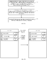
FIG. 2B is a schematic diagram of a setting user interface (UI) provided in implementations of the present disclosure. -
FIG. 2C is a schematic diagram of a setting UI provided in other implementations of the present disclosure. -
FIG. 2D is a schematic diagram of a WIFI setting UI provided in implementations of the present disclosure. -
FIG. 2E is a schematic diagram of displaying a first dialog box provided in implementations of the present disclosure. -
FIG. 3 is a schematic flow diagram of a method for network sharing provided in other implementations of the present disclosure. -
FIG. 4 is a schematic structural diagram of an electronic device provided in other implementations of the present disclosure. -
FIG. 5 is a schematic structural diagram of a device for network sharing provided in implementations of the present disclosure. - In order to enable those skilled in the art to better understand solutions of the present disclosure, technical solutions in implementations of the present disclosure will be described clearly and completely hereinafter with reference to the accompanying drawings in the implementations of the present disclosure. Apparently, the described implementations are merely some rather than all implementations of the present disclosure. All other implementations obtained by those of ordinary skill in the art based on the implementations of the present disclosure without creative efforts shall fall within the protection scope of the present disclosure.
- The following are described in detail.
- Hereinafter, method implementations of the disclosure will be interpreted in detail.
- The terms "first", "second", "third", "fourth", and the like used in the specification, the claims, and the accompany drawings of the present disclosure are used to distinguish different objects rather than describe a particular order. The terms "include", "comprise", and "have" as well as variations thereof are intended to cover non-exclusive inclusion. For example, a process, method, system, product, or apparatus including a series of steps or units is not limited to the listed steps or units, on the contrary, it can optionally include other steps or units that are not listed; alternatively, other steps or units inherent to the process, method, product, or device can be included either.
- The term "implementation" referred to herein means that a particular feature, structure, or feature described in conjunction with the implementation may be contained in at least one implementation of the present disclosure. The phrase appearing in various places in the specification does not necessarily refer to the same implementation, nor does it refer to an independent or alternative implementation that is mutually exclusive with other implementations. It is expressly and implicitly understood by those skilled in the art that an implementation described herein may be combined with other implementations.
-
FIG. 1A illustrates a communication system provided in implementations of the disclosure, referring toFIG. 1A , the communication system includes multiple electronic devices and multiple wireless Access Points (AP), and an AP is an access point of a WIFI network. In the implementations of the disclosure, the electronic device supports a dual-WIFI function, that is, the electronic device can access two WIFI networks. For example, the electronic device can accessWIFI network 1 through AP1 andWIFI network 2 through AP2. The electronic device supports coexistence of a WIFI function and a network sharing function. For example,electronic device 1 accessesWIFI network 1 through API, andelectronic device 1 creates a WIFI network, andelectronic device 2 accesses the WIFI network created by theelectronic device 1 through theelectronic device 1. Forms and numbers of the electronic devices and APs illustrated inFIG. 1A are by way of example only, and do not present a limitation on implementations of the disclosure. - The electronic device can include various handheld devices, vehicle-mounted devices, wearable devices, computing devices with a wireless communication function or other processing devices connected to a wireless modem, as well as various forms of User Equipment (UE), Mobile Station (MS), terminal device and the like.
-
FIG. 1B is a schematic structural diagram of an electronic device according to implementations of the present disclosure. As illustrated inFIG. 1B , the electronic device includes a processor, a memory, a signal processor, a transceiver, a display screen, a speaker, a microphone, a Random Access Memory (RAM), a camera, a sensor, a WIFI module, and the like. The memory, the signal processor, the display screen, the speaker, the microphone, the RAM, the camera, the sensor, and the WIFI module are connected with the processor, and the transceiver is connected with the signal processor. - The display screen can be a liquid crystal display (LCD), an organic light-emitting diode (OLED) or inorganic light-emitting diode, an active matrix organic light emitting diode (AMOLED), etc.
- The camera can be an ordinary camera or an infrared camera, which is not limited herein. The camera can be a front camera or a rear camera, which is not limited herein.
- The sensor includes at least one of the following: a light sensor, a gyroscope, an infrared proximity sensor, a fingerprint sensor, a pressure sensor, etc. The light sensor, also known as an ambient light sensor, is configured to detect brightness of ambient light. The light sensor may include a photosensitive element and an analog-to-digital converter. The photosensitive element is configured to convert a collected optical signal into an electrical signal, and the analog-to-digital converter is configured to convert the electrical signal into a digital signal. Optionally, the light sensor can also include a signal amplifier, which can amplify the electrical signal converted by the photosensitive element and then output it to the analog-to-digital converter. The photosensitive element may include at least one of a photodiode, a phototransistor, a photoresistor, and a silicon photocell.
- The processor is a control center of the electronic device, which connects all parts of the whole electronic device using various interfaces and lines. By running or executing software programs and/or modules stored in the memory and calling data stored in the memory, the processor can perform various functions of the electronic device and process data, so as to monitor the electronic device as a whole.
- The processor can be integrated with an application processor and a modem processor. The application processor mainly handles with an operating system, a user interface, and an application, and the modem processor mainly handles with wireless communications. It can be understood that the above modem processor may not be integrated into the processor.
- The memory is configured to store software programs and/or modules, and the processor executes various functional applications of the electronic device and processes data by running the software programs and/or modules stored in the memory. The memory can mainly include a program storage area and a data storage area. The operating system, software programs required by at least one function, etc. can be stored in the program storage area. Data created according to use of the electronic device and the like can be stored in the data storage area. In addition, the memory may include a highspeed random access memory, or may include a non-volatile memory, such as at least one magnetic disk memory device, flash memory device, or other volatile solid-state memory devices.
- The WIFI module supports a dual-WIFI (also known as dual-band WIFI) function so that the electronic device can operate at 2.4G and 5G simultaneously. With this WIFI module, one electronic device can access two different WIFI networks at the same time, so as to visit the Internet with the two WIFI networks at the same time, thus obtaining a greater transmission rate and lower network delay. The WIFI module can be, for example, a dual band dual concurrent (DBDC) module, a dual band simultaneous (DBS) module, or other chip modules.
- Implementations of the disclosure will be explained in detail below.
-
FIG. 2A is a schematic flow diagram of a method for network sharing provided in implementations of the present disclosure. The method for network sharing is applied to the above electronic device. As illustrated inFIG. 2A , the method specifically includes the following. - At 201, upon detecting a network-sharing enablement request, whether the electronic device has created two first network interfaces through the WIFI module is determined, the first network interfaces being used for WIFI network access.
- Optionally, the network network-sharing enablement request is triggered through a setting UI. For example, as illustrated in
FIG. 2B , a user can trigger the network-sharing enablement request by clicking a network-sharing setting switch. The network-sharing setting switch inFIG. 2B is currently in an off-state, and after the user clicks the network-sharing setting switch, the network-sharing setting switch is in an on-state. - Or, the network-sharing enablement request is triggered by voice. For example, the user triggers the network-sharing enablement request through voice control.
- Or, the network-sharing enablement request is triggered by another device. For example, the another device bound to the electronic device sends a control instruction, which is is used to instruct to enable network sharing.
- The network-sharing enablement request is used to request to enable network sharing.
- At 202, when the electronic device has created the two first network interfaces through the WIFI module, one of the two first network interfaces is released.
- Optionally, the electronic device currently accesses two WIFI networks through the two first network interfaces.
- Optionally, if the electronic device does not create the two first network interfaces through the WIFI module, the electronic device enables network sharing.
- The first network interface released by the electronic device is any one of the two first network interfaces; or, the electronic device has currently accessed (or, connected to) two WIFI networks through the two first network interfaces, and the first network interface released by the electronic device is a network interface associated with one of the two WIFI networks with less data transmission; or, the electronic device has currently accessed the two WIFI networks through the two first network interfaces, and the first network released by the electronic device is a network interface associated with a less important WIFI network among the two WIFI networks; or, the first network interface released by the electronic device is a network interface designated by the user among the two first network interfaces.
- At 203, network sharing is enabled once the one of the two first network interfaces is successfully released.
- Optionally, when the one of the two first network interfaces fails to be released, the electronic device continues to release the one of the two first network interfaces.
- In an implementation of the present disclosure, network sharing is enabled as follows.
- The electronic device creates a second network interface and creates a first WIFI network through the WIFI module. The electronic device shares the first WIFI network through the second network interface.
- Optionally, the electronic device shares the first WIFI network through the second network interface as follows.
- The electronic device creates a communication connection with other devices through the second network interface, and the created communication connection is used by the other devices to send and receive data through the first WIFI network, thereby sharing the first WIFI network.
- Optionally, after the electronic device enables network sharing, the method further includes the following.
- The electronic device disables network sharing, when network sharing is not used within a first duration.
- The first duration is, for example, 5 min, 8 min, 10 min, 13 min, or other values.
- That network sharing is not used means that there is no other devices which have accessed the first WIFI network created by the electronic device; and/or there is no other devices which are accessing the first WIFI network created by the electronic device.
- It can be seen that, in the implementations of the present disclosure, upon detecting the network-sharing enablement request, whether the electronic device has created two first network interfaces through the WIFI module is determined. When the electronic device has created the two first network interfaces through the WIFI module, one of the two first network interfaces is released. Once the one of the two first network interfaces is successfully released, network sharing is enabled. Since only one first network interface is released, coexistence of a Wi-Fi function and a network sharing function can be achieved and performance of the electronic device can be improved.
- In an implementation of the present disclosure, the method further includes the following after the electronic device enables network sharing.
- The electronic device determines whether network sharing is in use upon detecting that a dual-WIFI function of the electronic device is activated. The electronic device creates a third network interface through the WIFI module on condition that network sharing is not in use, and accesses a WIFI network through the third network interface.
- Activation of the dual-WIFI function is triggered through the setting UI. For example, as illustrated in
FIG. 2C , the user can activate the dual-WIFI function by clicking a dual-WIFI setting switch. The dual-WIFI setting switch inFIG. 2C is currently in an off-state, and the network-sharing setting switch is in an on-state. After the user clicks the dual-WIFI setting switch, the dual-WIFI setting switch is set to be in the on-state. - Or, the activation of the dual-WIFI function is triggered by voice. For example, the user activates the dual-WIFI function through voice control.
- Or, the activation of the dual-WIFI function is triggered by the electronic device based on a state of a WIFI network currently accessed by the electronic device. For example, when a signal strength of the WIFI network currently accessed by the electronic device is lower than a certain value, the electronic device activates the dual-WIFI function. For another example, when a transmission rate of the WIFI network currently accessed by the electronic device is lower than a certain value, the electronic device activates the dual-WIFI function.
- The electronic device determines whether network sharing is in use as follows. The electronic device determines whether there is another device which has accessed the first WIFI network created by the electronic device, and/or determines whether there is another device which is accessing the first WIFI network created by the electronic device. If there is no other devices which have accessed the first WIFI network, and/or no other devices which are accessing the first WIFI network, the electronic device determines that network sharing is not in use; otherwise, the electronic device determines network share is in use.
- Optionally, the method further includes that if network sharing is in use, the electronic device outputs a dual-WIFI function enablement failure prompt.
- It can be seen that, in this implementation of the present disclosure, the dual-WIFI function is allowed to be enabled only when network sharing is not in use, which ensures a priority of network sharing and improves stability of network sharing.
- In an implementation of the present disclosure, once the electronic device accesses two WIFI networks through the two first network interfaces, the electronic device releases the one of the two first network interfaces as follows.
- The electronic device determines at least two of a first numerical value, a second numerical value, a third numerical value, and a fourth numerical value, where the first numerical value is a total data amount sent by the electronic device using one of the two WIFI networks in the first time period, the second numerical value is a total data amount received by the electronic device using the one of the two WIFI networks in the first time period, the third numerical value is a total data amount sent by the electronic device using the other WIFI network of the two WIFI networks in the first time period, and the fourth numerical value is a total data amount received by the electronic device using the other WIFI network in the first time period, end time of the first time period being present moment. The electronic device determines a first target WIFI network based on the at least two of the first numerical value, the second numerical value, the third numerical value, and the fourth numerical value, the two WIFI networks including the first target WIFI network. The electronic device releases a first network interface associated with the first target WIFI network.
- The length of the first time period is, for example, 1 min, 2 min, 5 min, 10 min, 20 min, or other values.
- The two first network interfaces correspond to the two WIFI networks in a one-to-one correspondence. For example, the two first network interfaces include
first network interface 1 andfirst network interface 2, and the electronic device accesses one WIFI network throughfirst network interface 1 and accesses the other WIFI network throughfirst network interface 2. - In an implementation of the present disclosure, the electronic device determines the first target WIFI network based on the at least two of the first numerical value, the second numerical value, the third numerical value, and the fourth numerical value as follows.
- When a task currently processed by the electronic device includes a first task and the first task is processed using the two WIFI networks, the electronic device determines the first target WIFI network based on the second numerical value and the fourth numerical value, where in the first task, a total data amount expected to be received by the electronic device is greater than or equal to a first threshold.
- In an implementation of the present disclosure, the electronic device determines the first target WIFI network based on the second numerical value and the fourth numerical value as follows.
- The electronic device assigns one of the WIFI networks as the first target WIFI network on condition that the second numerical value is greater than the fourth numerical value. The electronic device assigns the other WIFI network as the first target WIFI network on condition that the second numerical value is less than the fourth numerical value.
- In the first task, a total data amount expected to be sent by the electronic device is less than the first threshold.
- The first task is, for example, a download task (such as a video download task, an audio download task, a file download task, etc.), or other tasks with a large amount of total data to be received.
- The first threshold can be 5 MB, 10 MB, 30 MB, 100 MB, or other values.
- The method for determining the first target WIFI network according to the implementation of the disclosure can be executed when the electronic device is in an off-screen state or when the electronic device is in an on-screen state, which is not limited herein.
- For example, assuming that there are two WIFI networks,
WIFI network 1 andWIFI network 2, the electronic device processes the video download task using the two WIFI networks, and in the first time period, a total amount of data received by the electronic device usingWIFI network 1 is 5 MB and a total amount of data received by the electronic device usingWIFI network 2 is 2 MB, then the electronic device takesWIFI network 2 as the target WIFI network. - It can be seen that in the implementations of the disclosure, the currently processed task is a task with a large amount of data to be received, and at this time, a receiving capacity of the electronic device in this task is mainly concerned, so it is only necessary to compare total data amounts received using the two WIFI networks, and in this way, determination efficiency for the WIFI networks can be improved.
- In an implementation of the disclosure, the electronic device determines the first target WIFI network based on at least two of the first numerical value, the second numerical value, the third numerical value, and the fourth numerical value as follows.
- When a task currently processed by the electronic device includes a second task and the second task is processed using the two WIFI networks, the electronic device determines the first target WIFI network based on first numerical value, the second numerical value, the third numerical value, and the fourth numerical.
- The electronic device determines the first target WIFI network based on the first numerical value, the second numerical value, the third numerical value, and the fourth numerical as follows.
- The electronic device assigns the one of the WIFI networks as the first target WIFI network when a sum of the first numerical value and the second numerical value is greater than a sum of the third numerical value and the fourth numerical value; assigns the other one of the WIFI networks as the first target WIFI network if the sum of the first numerical value and the second numerical value is less than the sum of the third numerical value and the fourth numerical value.
- In the second task, the total data amount expected to be received by the electronic device is greater than or equal to a second threshold, and/or the total data amount expected to be sent by the electronic device is greater than or equal to a third threshold, and/or the total data amount expected to be received by the electronic device is less than the second threshold, and/or the total data amount expected to be sent by the electronic device is less than the third threshold.
- The second threshold can be equal to the third threshold, the second threshold can be less than the third threshold, or the second threshold can be greater than the third threshold, which is not limited herein.
- The second threshold can be 3 MB, 4 MB, 5 MB, 10 MB, 30 MB, or other values. The third threshold can be 1 MB, 3 MB, 4 MB, 6 MB, 10 MB, 30 MB, or other values.
- The second task may be, for example, a download task, an upload task, an audio playback task, a video playback task, a reading task, a payment task, a call task or the like.
- The method for determining the first target WIFI network according to the implementation of the disclosure can be executed when the electronic device is in an off-screen state or when the electronic device is in an on-screen state, which is not limited herein.
- For example, assuming that there are two WIFI networks,
WIFI network 1 andWIFI network 2, and in the first time period, a total amount of data received by the electronic device withWIFI network 1 is 5 MB and a total amount of data sent by the electronic device withWIFI network 1 is 3 MB, and a total amount of data received by the electronic device withWIFI network 2 is 2 MB and a total amount of data sent by the electronic device withWIFI network 2 is 1 MB, then the electronic device takesWIFI network 2 as the target WIFI network. - It can be seen that in the implementation of the disclosure, the total data amount received and the total data amount sent using the two WIFI networks are used to determine the first target WIFI network, and because more data are used for determining, the determination accuracy for the WIFI network is improved.
- Optionally, the electronic device determines the first target WIFI network based on at least two of the first numerical value, the second numerical value, the third numerical value, and the fourth numerical value as follow.
- When a task currently processed by the electronic device includes a third task and the third task is processed using the two WIFI networks, the electronic device determines the first target WIFI network based on the first numerical value and the third numerical value, where in the third task, a total data amount expected to be sent by the electronic device is greater than or equal to a fourth threshold.
- The electronic device determines the first target WIFI network based on the first numerical value and the third numerical value as follows.
- The electronic device assigns the one of the WIFI networks as the first target WIFI network when the first numerical value is greater than the third numerical value; assigns the other one of the WIFI networks as the first target WIFI network when the first numerical value is greater than the third numerical value.
- In the third task, a total data amount expected to be received by the electronic device is less than the fourth threshold.
- The third task is, for example, an upload task (such as a video upload task, an audio upload task, a file upload task, etc.), or other tasks with a large amount of total data to be sent.
- The fourth threshold can be 4 MB, 5 MB, 15 MB, 35 MB, or other values.
- The method for determining the first target WIFI network according to the implementation of the disclosure can be executed when the electronic device is in an off-screen state or when the electronic device is in an on-screen state, which is not limited herein.
- For example, assuming that there are two WIFI networks,
WIFI network 1 andWIFI network 2, the electronic device processes the file upload task using the two WIFI networks, and in the first time period, a total amount of data sent by the electronic device withWIFI network 1 is 5 MB and a total amount of data sent by the electronic device withWIFI network 2 is 2 MB, then the electronic device takesWIFI network 2 as the first target WIFI network. - It can be seen that, in the implementation of the disclosure, the currently processed task is a task with a large amount of data to be sent, and at this time, a sending capacity of the electronic device in this task is mainly concerned, so it is only necessary to compare the total data amounts which are sent using the two WIFI networks, and in this way, determination efficiency for the WIFI networks can be improved.
- In an implementation of the present disclosure, once the electronic device accesses the two WIFI networks through the two first network interfaces, the electronic device releases the one of the two first network interfaces as follows.
- The electronic device determines an access priority and a signal strength of each of the two WIFI networks. The electronic device determines a second target WIFI network based on determined two access priorities and two signal strengths, the two WIFI networks including the second target WIFI network. The electronic device releases a first network interface associated with the second target WIFI network.
- The two first network interfaces correspond to the two WIFI networks in a one-to-one correspondence. For example, the two first network interfaces include
first network interface 1 andfirst network interface 2, and the electronic device accesses one WIFI network throughfirst network interface 1 and accesses the other WIFI network throughfirst network interface 2. - Optionally, the electronic device determines the signal strength of each of the two WIFI networks as follows.
- The electronic device reads a state of a signal strength indicator associated with each of the two WIFI networks. The electronic device determines the signal strength of each of the two WIFI networks based on two determined states of the signal strength indicator and a first mapping relationship, where the first mapping relationship is a mapping between states of the signal strength indicator and signal strengths.
- The first mapping relationship is shown in Table 1.
Table 1 States of a signal strength indicator Signal strength One- bar signal 1 Two- bar signal 2 Three- bar signal 3 - The state of the signal strength indicator is, for example, a one-bar signal, a two-bar signal, and a three-bar signal. As illustrated in
FIG. 2D , the electronic device currently accesses two WIFI networks, such asWIFI network 123 andWIFI network 2345. The state of the signal strength indicator ofWIFI network 123 is a two-bar signal, and the state of the signal strength indicator ofWIFI network 2345 is three-bar signal. Based on Table 1, the electronic device can determine that the signal strength ofWIFI network 123 is 2, and the signal strength ofWIFI network 2345 is 3. - Optionally, the electronic device determines the access priority of each of the two WIFI networks as follows.
- The electronic device determines the number of access times the electronic device accesses each of the two WIFI networks in a second time period, and end time of the second time period is the present moment. The electronic device determines the access priority of each of the two WIFI networks based on determined two access times and a second mapping relationship, where the second mapping relationship is a mapping between access times and access priorities.
- The length of the second time period is, for example, 5h, 10h, 20h, 1 day, 3 days, 10 days, or other values.
- The second mapping relationship is shown in Table 2. As shown in Table 2, the more the number of access times, the greater the corresponding access priority, and the less the number of access times, the lower the corresponding access priority.
Table 2 Access times Access priorities 1-5 1 6-12 2 13-20 3 ...... ...... - Optionally, the access priority of each of the two WIFI networks may be preset by the user. If an access priority of a certain WIFI network is not set, the access priority of the certain WIFI network is defined as a default priority (for example, access priority 2).
- Optionally, the electronic device determines the second target WIFI network based on the determined two access priorities and two signal strengths as follows.
- The electronic device determines an evaluation value of each of the two WIFI networks based on a first formula, the two access priorities, and the two signal strengths, and the evaluation value being used to evaluate an importance of a corresponding WIFI network. The electronic device determines the second target WIFI network based on determined two evaluation values.
- The first formula is: X=a∗Y+b∗Z, where X is an evaluation value, a and b are weights, the sum of a and b is equal to 1, Y is an access priority, and Z is a signal strength, a may be greater than b, may also be smaller than b, or may be equal to b, which is not limited here.
- The two WIFI networks include a first WIFI network and a second WIFI network, and the electronic device determines the second target WIFI network based on the two determined evaluation values as follows.
- If an evaluation value of the first WIFI network is less than an evaluation value of the second WIFI network, the electronic device assigns the first WIFI network as the second target WIFI network; if the evaluation value of the second WIFI network is less than the evaluation value of the first WIFI network, the electronic device assigns the second WIFI network as the second target WIFI network.
- For example, suppose that the two WIFI networks accessed by the electronic device include
WIFI network 1 andWIFI network 2, an access priority ofWIFI network 1 is 1, an access priority ofWIFI network 2 is 2, and a signal strength ofWIFI network 1 is 2, a signal strength ofWIFI network 2 is 3. If a=0.4, b=0.6, then an evaluation value ofWIFI network 1 is 0.4∗1+0.6∗2=1.6, and an evaluation value ofWIFI network 2 is 0.4 ∗2+0.6∗3=2.6, then the second target WIFI network isWIFI network 1. - It can be seen that in the implementation of the present disclosure, the importance of a WIFI network is comprehensively judged based on a WIFI access priority and signal strength, which improves the accuracy of determining the importance of the WIFI network, thereby ensuring rationality of releasing a network interface.
- In an implementation of the present disclosure, the electronic device releases the one of the two first network interfaces as follows.
- The electronic device displays a first dialog box on a display screen of the electronic device, where the first dialog box is used to prompt to select a network interface to be released from the two first network interfaces, and the first dialog box displays at least one of the following information: access state of a WIFI network through each of the two first network interfaces, a signal strength of an accessed WIFI network, and an access priority of the accessed WIFI network. The electronic device releases a first network interface selected by a selection operation upon detecting the selection operation against the first dialog box.
- Further, the network-sharing enablement request is triggered through an UI displayed on a display screen, as illustrated in
FIG. 2B . - The access state of a WIFI network through a first network interfaces may include accessing a certain WIFI network through the first network interface and not accessing the WIFI network through the first network interface.
- For example, suppose that the two first network interfaces created by the electronic device through the WIFI module include
first network interface 1 andfirst network interface 2. If the electronic device has accessedWIFI network 1 throughfirst network interface 1 and accessedWIFI network 2 throughfirst network interface 2, a signal strength of accessedWIFI network 1 is 1, a signal strength of accessedWIFI network 2 is 2, an access priority of accessedWIFI network 1 is 1, and an access priority of accessedWIFI network 2 is 2, a displayed first dialog box can be as illustrated inFIG. 2E . If the user clicks a virtual selection button of "First Network Interface 1" inFIG. 2E , the electronic device will releasefirst network interface 1. - It can be seen that, in the implementation of the present disclosure, the user is prompted to select a first network interface to be released by outputting a dialog box, which improves human-computer interaction experience. In addition, information of each first network interface is displayed through the dialog box, which ensures rationality of selecting a first network interface to be released by the user.
- In an implementation of the present disclosure, after the electronic device enables network sharing, K target devices access the first WIFI network created by the electronic device, where K is a positive integer, and the method further includes the following.
- The electronic device determines a distance between the electronic device and each of the target devices. If there are H distances greater than or equal to a fifth threshold among determined K distances, the electronic device determines a target signal transmission power based on the H distances, where H is a positive integer. The electronic device replaces a signal transmission power associated with the first WIFI network with the target signal transmission power.
- Optionally, the electronic device determines the distance between the electronic device and each of the target devices as follows.
- The electronic device broadcasts a detection request, where the detection request is used to request an immediate detection response after the detection request is received.
- After receiving the detection response sent by each of the target devices for the detection request, the electronic device determines the distance between the electronic device and each of the target devices based on a first moment and K second moments, where the first moment is a moment at which the detection request is sent, and the second moment is a moment at which a detection response is received.
- For example, suppose K=2, two target devices include
target device 1 andtarget device 2, a moment when a detection request is sent is t1, a moment when a detection response sent bytarget device 1 is received is t2, and a moment when a detection response sent bytarget device 2 is received is t3, and then a distance between the electronic device andtarget device 1 is (t2-t1)∗v, and a distance between the electronic device andtarget device 2 is (t3-t1)∗v, where v is a signal transmission speed. - Optionally, the electronic device determines the target signal transmission power based on the H distances as follows.
- The electronic device determines a target distance based on the H distances. The electronic device determines the target signal transmission power based on a second formula and the target distance, where the second formula is: W1=(S1/S2)∗W2, W1 and W2 are both signal transmission powers, W2 is a set signal transmission power, S1 and S2 are both distances, and S2 is a set distance.
- Optionally, the electronic device determines the target distance based on the H distances includes:
- If H is equal to 1, the electronic device determines that the target distance is the H distances. If H is greater than 1, the electronic device assigns an average distance of the H distances as the target distance, or the electronic device assigns the largest distance among the H distances as the target distance.
- It can be seen that, in the implementation of the present disclosure, after network sharing is enabled, the signal transmission power of the created WIFI network is adjusted based on the distances between the electronic device and the target devices accessing the WIFI network created by the electronic device, thereby increasing the signal strength of the created WIFI network and improving stability of network sharing.
- Consistent with the implementations illustrated in
FIG. 2A ,FIG. 3 is a schematic flow diagram of a method for network sharing provided in other implementations of the present disclosure. Reference is made toFIG. 3 , the method for network sharing is applied to the above electronic device, and specifically includes following operations. - At 301, the electronic device detects a network-sharing enablement request.
- When the network-sharing enablement request is detected, proceed to operations at 302. When the network-sharing enablement request is not detected, continue operations at 301.
- At 302, the electronic device determines whether the electronic device has created two first network interfaces through a WIFI module of the electronic device, the first network interfaces being used for WIFI network access.
- If YES, proceed to operations at 303; otherwise, proceed to operations at 307.
- Furthermore, the electronic device has accessed two WIFI networks through the two first network interfaces.
- At 303, the electronic device determines an access priority and a signal strength of each of the two WIFI networks.
- At 304, the electronic device determines an evaluation value of each of the two WIFI networks based on a first formula, two access priorities, and two signal strengths, and the evaluation value being used to evaluate an importance of a corresponding WIFI network
- At 305, the electronic device determines a second target WIFI network based on determined two evaluation values, the two WIFI networks including the second target WIFI network.
- At 306, the electronic device releases a first network interface associated with the second target WIFI network.
- When first network interface is released successfully, proceed to operations at 307.
- When first network interface is not released successfully, proceed to operations at 306.
- At 307, the electronic device creates a second network interface and creates a first WIFI network through the WIFI module.
- At 308, the electronic device shares the first WIFI network through the second network interface.
- At 309, the electronic device detects whether a dual-WIFI function of the electronic device is activated.
- If YES, proceed to operations at 310; otherwise, perform no operations.
- At 310, the electronic device determines whether network sharing is in use.
- If YES, perform no operations; otherwise, proceed to operations at 311.
- At 311, the electronic device creates a third network interface through the WIFI module on condition that network sharing is not in use, and accesses a WIFI network through the third network interface.
- It should be noted that reference of a specific implementation process of this implementation can be made to a specific implementation process described in the foregoing method implementations, which will not be described here.
- As is consistent with the above-mentioned implementations illustrated in
FIGs. 2A and 3A, reference is made toFIG. 4 , which is a structural schematic diagram of an electronic device provided in implementations of the disclosure. As illustrated, the electronic device includes a processor, a memory, a communication interface, and one or more programs. The one or more programs are stored in the memory and configured to be executed by the processor, and the programs include instructions for executing following operations. - Upon detecting a network-sharing enablement request, whether the electronic device has created two first network interfaces through a WIFI module of the electronic device is determined, the first network interfaces being used for WIFI network access. One of the two first network interfaces is released on condition that the electronic device has created the two first network interfaces through the WIFI module. Network sharing is enabled once the one of the two first network interfaces is successfully released.
- It can be seen that, in the implementations of the present disclosure, upon detecting the network-sharing enablement request, whether the electronic device has created two first network interfaces through the WIFI module is determined. When the electronic device has created the two first network interfaces through the WIFI module, one of the two first network interfaces is released. Once the one of the two first network interfaces is successfully released, network sharing is enabled. Since only one first network interface is released, coexistence of a Wi-Fi function and a network sharing function can be achieved and performance of an electronic device can be improved.
- In an implementation of the present disclosure, in term of enabling network sharing, the programs include instructions for executing following operations.
- A second network interface is created and a first WIFI network is created, through the WIFI module. The first WIFI network is shared through the second network interface.
- In an implementation of the present disclosure, the programs further include instructions for executing following operations.
- After network sharing is enabled, whether network sharing is in use is determined upon detecting that a dual-WIFI function of the electronic device is activated. A third network interface is created through the WIFI module on condition that network sharing is not in use, and a WIFI network is accessed through the third network interface.
- In an implementation of the present disclosure, the electronic device accesses two WIFI networks through the two first network interfaces, in terms of releasing the one of the two first network interfaces, the programs include instructions for executing following operations.
- At least two of a first numerical value, a second numerical value, a third numerical value, and a fourth numerical value are determined, where the first numerical value is a total data amount sent by the electronic device using one of the two WIFI networks in the first time period, the second numerical value is a total data amount received by the electronic device using the one of the two WIFI networks in the first time period, the third numerical value is a total data amount sent by the electronic device using the other WIFI network of the two WIFI networks in the first time period, and the fourth numerical value is a total data amount received by the electronic device using the other WIFI network in the first time period, end time of the first time period being present moment. A first target WIFI network is determined based on the at least two of the first numerical value, the second numerical value, the third numerical value, and the fourth numerical value, the two WIFI networks including the first target WIFI
- network. A first network interface associated with the first target WIFI network is released.
- In an implementation of the present disclosure, the electronic device accesses two WIFI networks through the two first network interfaces, in terms of releasing the one of the two first network interfaces, the programs include instructions for executing following operations.
- An access priority and a signal strength of each of the two WIFI networks are determined. A second target WIFI network is determined based on determined two access priorities and two signal strengths, the two WIFI networks including the second target WIFI network. A first network interface associated with the second target WIFI network is released.
- In an implementation of the present disclosure, in terms of determining the second target WIFI network based on the determined two access priorities and two signal strengths, the programs include instructions for executing following operations.
- An evaluation value of each of the two WIFI networks is determined based on a first formula, the two access priorities, and the two signal strengths, and the evaluation value being used to evaluate an importance of a corresponding WIFI network. The second target WIFI network is determined based on determined two evaluation values.
- In an implementation of the present disclosure, in terms of releasing the one of the two first network interfaces, the programs include instructions for executing following operations.
- A first dialog box is displayed on a display screen of the electronic device, where the first dialog box is used to prompt to select a network interface to be released from the two first network interfaces, and the first dialog box displays at least one of the following information: access state of a WIFI network through each of the two first network interfaces, a signal strength of an accessed WIFI network, and an access priority of the accessed WIFI network. A first network interface selected by a selection operation is released upon detecting the selection operation against the first dialog box.
- It should be noted that a specific implementation process of this implementation can be referred to the specific implementation process described in the above method implementation, and will not be repeatedly described here.
- Reference is made to
FIG. 5 , which is a schematic structural diagram of a device for network sharing provided in implementations of the present disclosure, the device for network sharing is applied to an electronic device, and the device for network sharing includes a first determiningunit 501, aninterface control unit 502, and anetwork control unit 503. - The first determining
unit 501 is configured to determine whether the electronic device has created two first network interfaces through the WIFI module upon detecting a network-sharing enablement request, the first network interfaces being used for WIFI network access. - The
interface control unit 502 is configured to release one of the two first network interfaces on condition that the electronic device has created the two first network interfaces through the WIFI module. - The
network control unit 503 is configured to enable network sharing once the one of the two first network interfaces is successfully released. - It can be seen that, in the implementations of the present disclosure, upon detecting the network-sharing enablement request, whether the electronic device has created two first network interfaces through the WIFI module is determined. When the electronic device has created the two first network interfaces through the WIFI module, one of the two first network interfaces is released. Once the one of the two first network interfaces is successfully released, network sharing is enabled. Since only one first network interface is released, coexistence of a Wi-Fi function and a network sharing function can be achieved and performance of an electronic device can be improved.
- In an implementation of the present disclosure, in terms of enabling network sharing, the
network control unit 503 is configured to: create a second network interface and create a first WIFI network, through the WIFI module; share the first WIFI network through the second network interface. - In an implementation of the present disclosure, the device further includes a second determining
unit 504. - The second determining
unit 504 is configured to determine whether network sharing is in use after enabling network sharing by thenetwork control unit 503 and upon detecting that a dual-WIFI function of the electronic device is activated. - The
interface control unit 502 is configured to create a third network interface through the WIFI module on condition that network sharing is not in use; - The
network control unit 503 is configured to access a WIFI network through the third network interface. - In an implementation of the present disclosure, once the electronic device accesses two WIFI networks through the two first network interfaces, in terms of releasing the one of the two first network interfaces, the interface control unit 502 is configured to: determine at least two of a first numerical value, a second numerical value, a third numerical value, and a fourth numerical value, where the first numerical value is a total data amount sent by the electronic device using one of the two WIFI networks in the first time period, the second numerical value is a total data amount received by the electronic device using the one of the two WIFI networks in the first time period, the third numerical value is a total data amount sent by the electronic device using the other WIFI network of the two WIFI networks in the first time period, and the fourth numerical value is a total data amount received by the electronic device using the other WIFI network in the first time period, end time of the first time period being present moment; determine a first target WIFI network based on the at least two of the first numerical value, the second numerical value, the third numerical value, and the fourth numerical value, the two WIFI networks including the first target WIFI network; release a first network interface associated with the first target WIFI network.
- In an implementation of the present disclosure, once the electronic device accesses two WIFI networks through the two first network interfaces, in terms of releasing the one of the two first network interfaces, the
interface control unit 502 is configured to: determine an access priority and a signal strength of each of the two WIFI networks; determine a second target WIFI network based on determined two access priorities and two signal strengths, the two WIFI networks including the second target WIFI network; release a first network interface associated with the second target WIFI network. - In an implementation of the present disclosure, in terms of determining the second target WIFI network based on the determined two access priorities and two signal strengths, the
interface control unit 502 is configured to: determine an evaluation value of each of the two WIFI networks based on a first formula, the two access priorities, and the two signal strengths, and the evaluation value being used to evaluate an importance of a corresponding WIFI network; determine the second target WIFI network based on determined two evaluation values. - In an implementation of the present disclosure, in terms of releasing the one of the two first network interfaces, the
interface control unit 502 is configured to: display a first dialog box on a display screen of the electronic device, where the first dialog box is used to prompt to select a network interface to be released from the two first network interfaces, and the first dialog box displays at least one of the following information: access state of a WIFI network through each of the two first network interfaces, a signal strength of an accessed WIFI network, and an access priority of the accessed WIFI network; release a first network interface selected by a selection operation upon detecting the selection operation against the first dialog box. - It should be noted that, the a first determining
unit 501, theinterface control unit 502, thenetwork control unit 503, and second determiningunit 504 of the electronic device can be realized by a processor. - Implementations of the present disclosure further provide a computer-readable storage medium. The computer-readable storage medium stores a computer program for Electronic Data Interchange (EDI). The computer program causes a computer to perform some or all of operations as described for the electronic device in the above method implementations.
- Implementations of the present disclosure further provide a computer program product. The computer program product includes a non-transitory computer readable storage medium storing a computer program. The computer program is operable to cause a computer to perform some or all of operations as described for the electronic device in the above method implementations. The computer program product can be a software installation package.
- The operations of the method or algorithm described in the implementations of the disclosure can be realized in hardware or by the processor executing software instructions. The software instructions can be composed of corresponding software modules, which can be stored in random access memory (RAM), flash memory, Read Only Memory (ROM), erasable programmable ROM (EPROM), electrically EPROM (EEPROM), register, hard disk, removable hard disk, CD-ROM or any other form of storage medium known in the art. An exemplary storage medium is coupled to the processor so that the processor can read information from and write information to the storage medium. Of course, the storage medium can also be an integral part of the processor. The processor and the storage medium may be located in an ASIC. In addition, the ASIC can be located in an access network device, a target network device or a core network device. Of course, the processor and the storage medium can also exist as discrete components in the access network device, the target network device or the core network device.
- Those skilled in the art should realize that in one or more of the above examples, functions described in the implementations of the disclosure can be realized in whole or in part in software, hardware, firmware or any combination thereof. When implemented in software, it can be fully or partially implemented in a form of a computer program product. The computer program product includes one or more computer instructions. When the computer program instructions are loaded and executed on a computer, all or part of the processes or functions described in the implementations of the disclosure are generated. The computer can be a general-purpose computer, a special-purpose computer, a computer network, or other programmable devices. The computer instructions can be stored in a computer-readable storage medium or transmitted from one computer-readable storage medium to another computer-readable storage medium. For example, the computer instructions can be transmitted from one website site, computer, server or data center to another website site, computer, server or data center by wire (such as a coaxial cable, an optical fiber, and a digital subscriber line (DSL)) or wirelessly (such as infrared, radio, microwave, etc.). The computer-readable storage medium can be any available medium that a computer can access or a data storage device including one or more available media integrated servers, data centers or the like. The available media can be magnetic media (e.g., floppy disk, hard disk, and magnetic tape), optical media (e.g., digital video disc (DVD)), or semiconductor media (e.g., solid state disk (SSD)), etc.
- The purposes, technical schemes and beneficial effects of the disclosure are detailed in specific implementations described above. It should be understood that the above description is only the specific implementations of the disclosure and is not intended to limit a protection scope of the disclosure. Any modification, equivalent replacement, improvement, etc. on a basis of the technical schemes of the disclosure should be encompassed in the protection scope of the disclosure.
Claims (20)
- A method for network sharing, applied to an electronic device with a WIFI module and comprising:upon detecting a network-sharing enablement request, determining whether the electronic device has created two first network interfaces through the WIFI module the first network interfaces being used for WIFI network access;releasing one of the two first network interfaces on condition that the electronic device has created the two first network interfaces through the WIFI module; andenabling network sharing once the one of the two first network interfaces is successfully released.
- The method of claim 1, wherein enabling network sharing comprises:creating a second network interface and creating a first WIFI network, through the WIFI module; andsharing the first WIFI network through the second network interface.
- The method of claim 1 or 2, further comprising:
after enabling network sharing,determining whether network sharing is in use upon detecting that a dual-WIFI function of the electronic device is activated; andcreating a third network interface through the WIFI module on condition that network sharing is not in use, and accessing a WIFI network through the third network interface. - The method of any of claims 1 to 3, wherein once the electronic device accesses two WIFI networks through the two first network interfaces, releasing the one of the two first network interfaces comprises:determining at least two of a first numerical value, a second numerical value, a third numerical value, and a fourth numerical value, wherein the first numerical value is a total data amount sent by the electronic device using one of the two WIFI networks in the first time period, the second numerical value is a total data amount received by the electronic device using the one of the two WIFI networks in the first time period, the third numerical value is a total data amount sent by the electronic device using the other WIFI network of the two WIFI networks in the first time period, and the fourth numerical value is a total data amount received by the electronic device using the other WIFI network in the first time period, end time of the first time period being present moment;determining a first target WIFI network based on the at least two of the first numerical value, the second numerical value, the third numerical value, and the fourth numerical value, the two WIFI networks comprising the first target WIFI network; andreleasing a first network interface associated with the first target WIFI network.
- The method of claim 4, wherein determining the first target WIFI network based on the at least two of the first numerical value, the second numerical value, the third numerical value, and the fourth numerical value comprises:
determining the first target WIFI network based on the second numerical value and the fourth numerical value when a task currently processed by the electronic device comprises a first task and the first task is processed using the two WIFI networks, in the first task, a total data amount expected to be received by the electronic device being greater than or equal to a first threshold. - The method of claim 5, wherein determining the first target WIFI network based on the second numerical value and the fourth numerical value comprises:assigning one of the WIFI networks as the first target WIFI network on condition that the second numerical value is greater than the fourth numerical value; andassigning the other WIFI network as the first target WIFI network on condition that the second numerical value is less than the fourth numerical value.
- The method of any of claims 1 to 3, wherein once the electronic device accesses two WIFI networks through the two first network interfaces, releasing the one of the two first network interfaces comprises:determining an access priority and a signal strength of each of the two WIFI networks;determining a second target WIFI network based on determined two access priorities and two signal strengths, the two WIFI networks comprising the second target WIFI network; andreleasing a first network interface associated with the second target WIFI network.
- The method of claim 7, wherein determining the second target WIFI network based on the determined two access priorities and two signal strengths comprises:determining an evaluation value of each of the two WIFI networks based on a first formula, the two access priorities, and the two signal strengths, and the evaluation value being used to evaluate an importance of a corresponding WIFI network; anddetermining the second target WIFI network based on determined two evaluation values.
- The method of any of claims 1 to 3, wherein releasing the one of the two first network interfaces comprises:displaying a first dialog box on a display screen of the electronic device, wherein the first dialog box is used to prompt to select a network interface to be released from the two first network interfaces, and the first dialog box displays at least one of the following information: access state of a WIFI network through each of the two first network interfaces, a signal strength of an accessed WIFI network, and an access priority of the accessed WIFI network; andreleasing a first network interface selected by a selection operation upon detecting the selection operation against the first dialog box.
- A device for network sharing, applied to an electronic device with a WIFI module and comprising:a first determining unit configured to determine whether the electronic device has created two first network interfaces through the WIFI module upon detecting a network-sharing enablement request, the first network interfaces being used for WIFI network access;an interface control unit configured to release one of the two first network interfaces on condition that the electronic device has created the two first network interfaces through the WIFI module; anda network control unit configured to enable network sharing once the one of the two first network interfaces is successfully released.
- The device of claim 10, wherein in terms of enabling network sharing, the network control unit is configured to:create a second network interface and create a first WIFI network, through the WIFI module; andshare the first WIFI network through the second network interface.
- The device of claim 10 or 11, further comprising:a second determining unit configured to determine whether network sharing is in use after enabling network sharing by the network control unit and upon detecting that a dual-WIFI function of the electronic device is activated; andthe interface control unit being configured to create a third network interface through the WIFI module on condition that network sharing is not in use;the network control unit being configured to access a WIFI network through the third network interface.
- The device of any of claims 10 to 12, wherein once the electronic device accesses two WIFI networks through the two first network interfaces, in terms of releasing the one of the two first network interfaces, the interface control unit is configured to:determine at least two of a first numerical value, a second numerical value, a third numerical value, and a fourth numerical value, wherein the first numerical value is a total data amount sent by the electronic device using one of the two WIFI networks in the first time period, the second numerical value is a total data amount received by the electronic device using the one of the two WIFI networks in the first time period, the third numerical value is a total data amount sent by the electronic device using the other WIFI network of the two WIFI networks in the first time period, and the fourth numerical value is a total data amount received by the electronic device using the other WIFI network in the first time period, end time of the first time period being present moment;determine a first target WIFI network based on the at least two of the first numerical value, the second numerical value, the third numerical value, and the fourth numerical value, the two WIFI networks comprising the first target WIFI network; andrelease a first network interface associated with the first target WIFI network.
- The device of claim 13, wherein in terms of determining the first target WIFI network based on the at least two of the first numerical value, the second numerical value, the third numerical value, and the fourth numerical value, the interface control unit is configured to:
determine the first target WIFI network based on the second numerical value and the fourth numerical value when a task currently processed by the electronic device comprises a first task and the first task is processed using the two WIFI networks, in the first task, a total data amount expected to be received by the electronic device being greater than or equal to a first threshold. - The device of claim 14, wherein in terms of determining the first target WIFI network based on the second numerical value and the fourth numerical value, the interface control unit is configured to:assign one of the WIFI networks as the first target WIFI network on condition that the second numerical value is greater than the fourth numerical value; andassign the other WIFI network as the first target WIFI network on condition that the second numerical value is less than the fourth numerical value.
- The device of any of claims 10 to 12, wherein once the electronic device accesses two WIFI networks through the two first network interfaces, in terms of releasing the one of the two first network interfaces, the interface control unit is configured to:determine an access priority and a signal strength of each of the two WIFI networks;determine a second target WIFI network based on determined two access priorities and two signal strengths, the two WIFI networks comprising the second target WIFI network; andrelease a first network interface associated with the second target WIFI network.
- The device of claim 16, wherein in terms of determining the second target WIFI network based on the determined two access priorities and two signal strengths, the interface control unit is configured to:determine an evaluation value of each of the two WIFI networks based on a first formula, the two access priorities, and the two signal strengths, and the evaluation value being used to evaluate an importance of a corresponding WIFI network; anddetermine the second target WIFI network based on determined two evaluation values.
- The device of any of claims 10 to 12, wherein in terms of releasing the one of the two first network interfaces, the interface control unit is configured to:display a first dialog box on a display screen of the electronic device, wherein the first dialog box is used to prompt to select a network interface to be released from the two first network interfaces, and the first dialog box displays at least one of the following information: access state of a WIFI network through each of the two first network interfaces, a signal strength of an accessed WIFI network, and an access priority of the accessed WIFI network; andrelease a first network interface selected by a selection operation upon detecting the selection operation against the first dialog box.
- An electronic device, comprising a processor, a memory, a communication interface, and one or more programs, wherein the one or more programs are stored in the memory and configured to be executed by the processor, and the programs comprise instructions for executing operations of the method of any of claims 1 to 9.
- A computer-readable storage medium storing a computer program, wherein the computer program is processed to execute the method of any of claims 1 to 9.
Applications Claiming Priority (2)
| Application Number | Priority Date | Filing Date | Title |
|---|---|---|---|
| CN201910819989.1A CN110536016B (en) | 2019-08-31 | 2019-08-31 | Network sharing method and related equipment |
| PCT/CN2020/102108 WO2021036556A1 (en) | 2019-08-31 | 2020-07-15 | Network sharing method and related device |
Publications (3)
| Publication Number | Publication Date |
|---|---|
| EP4013023A1 true EP4013023A1 (en) | 2022-06-15 |
| EP4013023A4 EP4013023A4 (en) | 2022-10-12 |
| EP4013023B1 EP4013023B1 (en) | 2024-02-28 |
Family
ID=68665895
Family Applications (1)
| Application Number | Title | Priority Date | Filing Date |
|---|---|---|---|
| EP20856266.0A Active EP4013023B1 (en) | 2019-08-31 | 2020-07-15 | Network sharing method and related device |
Country Status (4)
| Country | Link |
|---|---|
| US (1) | US12389475B2 (en) |
| EP (1) | EP4013023B1 (en) |
| CN (1) | CN110536016B (en) |
| WO (1) | WO2021036556A1 (en) |
Families Citing this family (5)
| Publication number | Priority date | Publication date | Assignee | Title |
|---|---|---|---|---|
| CN110536016B (en) * | 2019-08-31 | 2021-04-20 | Oppo广东移动通信有限公司 | Network sharing method and related equipment |
| CN114339897B (en) * | 2020-09-30 | 2025-05-27 | 华为技术有限公司 | Data transmission method, electronic device, chip system and storage medium |
| CN113490291B (en) * | 2021-06-16 | 2022-05-17 | 荣耀终端有限公司 | Data download method, device and terminal device |
| JP2024082763A (en) * | 2022-12-09 | 2024-06-20 | キヤノン株式会社 | COMMUNICATION DEVICE, CONTROL METHOD AND PROGRAM FOR COMMUNICATION DEVICE |
| CN121645554A (en) * | 2024-08-19 | 2026-03-10 | 荣耀终端股份有限公司 | A network sharing method, electronic device, and chip system |
Family Cites Families (25)
| Publication number | Priority date | Publication date | Assignee | Title |
|---|---|---|---|---|
| US8559369B2 (en) * | 2006-02-22 | 2013-10-15 | Elad Barkan | Wireless internet system and method |
| FR2954877B1 (en) * | 2009-12-30 | 2012-05-25 | Thales Sa | METHOD FOR CONTROLLING COMMNICATIONS IN A MOBILE AD HOC NETWORK |
| FR2979784A1 (en) * | 2011-09-02 | 2013-03-08 | France Telecom | CHANNEL SELECTION METHOD, WIFI EQUIPMENT AND CORRESPONDING COMPUTER PROGRAM |
| CN102917406B (en) * | 2012-08-02 | 2016-04-06 | 华为技术有限公司 | Data traffic shunt method and equipment |
| US20140105125A1 (en) * | 2012-10-16 | 2014-04-17 | Qualcomm Incorporated | Criteria for ue-initiated bearer deactivation when maximum number of active bearers has been reached |
| CN202873086U (en) * | 2012-10-31 | 2013-04-10 | 上海斐讯数据通信技术有限公司 | Wireless double-frequency AP (Access Point) |
| US9706383B2 (en) * | 2013-01-04 | 2017-07-11 | Nokia Technologies Oy | Method, apparatus, and computer program product for configuring a mobile wireless hotspot |
| US9907085B2 (en) * | 2014-09-26 | 2018-02-27 | Avago Technologies General Ip (Singapore) Pte. Ltd. | WIFI-coordinated LAA-LTE |
| US10230522B1 (en) * | 2016-03-24 | 2019-03-12 | Amazon Technologies, Inc. | Network access control |
| CN106055199B (en) | 2016-05-26 | 2019-08-16 | 努比亚技术有限公司 | A kind of information synchronization method and electronic equipment |
| CN110545281B (en) * | 2016-05-27 | 2022-01-18 | 华为技术有限公司 | WIFI network access method and device |
| CN106304101A (en) | 2016-07-29 | 2017-01-04 | 北京小米移动软件有限公司 | Share the method and device of network |
| CN106131877A (en) * | 2016-08-11 | 2016-11-16 | 广州视源电子科技股份有限公司 | WiFi communication processing device, method and system |
| CN106332217A (en) * | 2016-08-22 | 2017-01-11 | 维沃移动通信有限公司 | Wireless routing method and mobile terminal |
| KR20170095772A (en) * | 2017-08-04 | 2017-08-23 | 정예담 | WiFi Cell Phone |
| CN107580359B (en) * | 2017-09-29 | 2020-11-03 | 新沂市摩尔网络科技有限公司 | Wireless hotspot sharing method, mobile terminal and computer readable storage medium |
| CN108307433B (en) * | 2017-09-29 | 2021-06-15 | 努比亚技术有限公司 | Wireless hotspot sharing method, mobile terminal and computer readable storage medium |
| CN112965465B (en) * | 2018-01-19 | 2022-07-08 | 深圳市道通科技股份有限公司 | Automobile diagnostic instrument, operation system method thereof and automobile diagnostic system |
| CN108601063B (en) | 2018-03-09 | 2021-08-24 | Oppo广东移动通信有限公司 | Personal hotspot implementation method and related products |
| WO2019232497A1 (en) * | 2018-05-31 | 2019-12-05 | Mobophiles, Inc. | Systems and methods for dynamic channel bonding |
| CN109218987A (en) * | 2018-09-28 | 2019-01-15 | Oppo广东移动通信有限公司 | Information processing method, device, terminal and storage medium |
| CN109219088B (en) | 2018-11-21 | 2021-08-17 | Oppo(重庆)智能科技有限公司 | Network sharing method and network sharing device |
| US11240734B2 (en) * | 2019-08-05 | 2022-02-01 | Arris Enterprises Llc | Utilizing blacklist steering to prevent rejection of BSS transition management (BTM) steering |
| US20210058787A1 (en) * | 2019-08-23 | 2021-02-25 | Charles Isgar | Wifi sharing system |
| CN110536016B (en) * | 2019-08-31 | 2021-04-20 | Oppo广东移动通信有限公司 | Network sharing method and related equipment |
-
2019
- 2019-08-31 CN CN201910819989.1A patent/CN110536016B/en not_active Expired - Fee Related
-
2020
- 2020-07-15 EP EP20856266.0A patent/EP4013023B1/en active Active
- 2020-07-15 WO PCT/CN2020/102108 patent/WO2021036556A1/en not_active Ceased
-
2022
- 2022-02-07 US US17/666,195 patent/US12389475B2/en active Active
Also Published As
| Publication number | Publication date |
|---|---|
| WO2021036556A1 (en) | 2021-03-04 |
| CN110536016A (en) | 2019-12-03 |
| US20220159765A1 (en) | 2022-05-19 |
| CN110536016B (en) | 2021-04-20 |
| EP4013023B1 (en) | 2024-02-28 |
| EP4013023A4 (en) | 2022-10-12 |
| US12389475B2 (en) | 2025-08-12 |
Similar Documents
| Publication | Publication Date | Title |
|---|---|---|
| US12389475B2 (en) | Method for network sharing and related devices | |
| US12271575B2 (en) | Method for displaying different application shortcuts on different screens | |
| US10635449B2 (en) | Method and apparatus for running game client | |
| US20190260854A1 (en) | Method for controlling cooperation of multiple intelligent devices and apparatus thereof | |
| US10956280B2 (en) | Data backup method, electronic device, and storage medium | |
| US11188225B2 (en) | Touch control method and apparatus | |
| KR102150624B1 (en) | Method and apparatus for notifying smishing | |
| US20170237930A1 (en) | Method of controlling the sharing of videos and electronic device adapted thereto | |
| US10609276B2 (en) | Electronic device and method for controlling operation of camera-related application based on memory status of the electronic device thereof | |
| JP7605533B2 (en) | Device control method and terminal device | |
| US11109226B2 (en) | Information process method, computer readable storage medium and computer device | |
| US10802623B2 (en) | Electronic device and screen display method thereof | |
| CN108322602B (en) | Method, terminal and computer readable storage medium for processing application no response | |
| EP4446883A1 (en) | Method for preloading memory page, electronic device, and chip system | |
| US9621986B2 (en) | Electronic device, audio device, and method for supplying power to the audio device | |
| CN104915091A (en) | Method and device for displaying status bar prompt message | |
| KR102239563B1 (en) | Electronic device and method for searching for access point in local area network at electronic device | |
| KR20170019733A (en) | Electronic device and method for improving performance of antenna of the same | |
| US10075798B2 (en) | Method for providing audio and electronic device adapted to the same | |
| EP4021026A1 (en) | Notification message control method and related apparatus | |
| CN110572208A (en) | Method and related equipment for network switching | |
| KR20150068136A (en) | Contents download method of electronic apparatus and electronic appparatus thereof | |
| US10917842B2 (en) | Access point connection method and terminal | |
| EP3843343A1 (en) | Wireless communication method and electronic device supporting same | |
| CN116243942A (en) | Firmware upgrade method, device and computer-readable storage medium |
Legal Events
| Date | Code | Title | Description |
|---|---|---|---|
| STAA | Information on the status of an ep patent application or granted ep patent |
Free format text: STATUS: THE INTERNATIONAL PUBLICATION HAS BEEN MADE |
|
| PUAI | Public reference made under article 153(3) epc to a published international application that has entered the european phase |
Free format text: ORIGINAL CODE: 0009012 |
|
| STAA | Information on the status of an ep patent application or granted ep patent |
Free format text: STATUS: REQUEST FOR EXAMINATION WAS MADE |
|
| 17P | Request for examination filed |
Effective date: 20220307 |
|
| AK | Designated contracting states |
Kind code of ref document: A1 Designated state(s): AL AT BE BG CH CY CZ DE DK EE ES FI FR GB GR HR HU IE IS IT LI LT LU LV MC MK MT NL NO PL PT RO RS SE SI SK SM TR |
|
| A4 | Supplementary search report drawn up and despatched |
Effective date: 20220913 |
|
| RIC1 | Information provided on ipc code assigned before grant |
Ipc: H04W 84/12 20090101ALN20220907BHEP Ipc: H04W 76/34 20180101ALN20220907BHEP Ipc: H04M 1/72412 20210101ALI20220907BHEP Ipc: H04W 76/15 20180101AFI20220907BHEP |
|
| DAV | Request for validation of the european patent (deleted) | ||
| DAX | Request for extension of the european patent (deleted) | ||
| REG | Reference to a national code |
Ref country code: DE Free format text: PREVIOUS MAIN CLASS: H04M0001725000 Ipc: H04W0076150000 Ref country code: DE Ref legal event code: R079 Ref document number: 602020026580 Country of ref document: DE Free format text: PREVIOUS MAIN CLASS: H04M0001725000 Ipc: H04W0076150000 |
|
| GRAP | Despatch of communication of intention to grant a patent |
Free format text: ORIGINAL CODE: EPIDOSNIGR1 |
|
| STAA | Information on the status of an ep patent application or granted ep patent |
Free format text: STATUS: GRANT OF PATENT IS INTENDED |
|
| RIC1 | Information provided on ipc code assigned before grant |
Ipc: H04W 84/12 20090101ALN20231116BHEP Ipc: H04W 76/34 20180101ALN20231116BHEP Ipc: H04M 1/72412 20210101ALI20231116BHEP Ipc: H04W 76/15 20180101AFI20231116BHEP |
|
| RIC1 | Information provided on ipc code assigned before grant |
Ipc: H04W 84/12 20090101ALN20231129BHEP Ipc: H04W 76/34 20180101ALN20231129BHEP Ipc: H04M 1/72412 20210101ALI20231129BHEP Ipc: H04W 76/15 20180101AFI20231129BHEP |
|
| INTG | Intention to grant announced |
Effective date: 20231212 |
|
| GRAS | Grant fee paid |
Free format text: ORIGINAL CODE: EPIDOSNIGR3 |
|
| GRAA | (expected) grant |
Free format text: ORIGINAL CODE: 0009210 |
|
| STAA | Information on the status of an ep patent application or granted ep patent |
Free format text: STATUS: THE PATENT HAS BEEN GRANTED |
|
| AK | Designated contracting states |
Kind code of ref document: B1 Designated state(s): AL AT BE BG CH CY CZ DE DK EE ES FI FR GB GR HR HU IE IS IT LI LT LU LV MC MK MT NL NO PL PT RO RS SE SI SK SM TR |
|
| REG | Reference to a national code |
Ref country code: GB Ref legal event code: FG4D |
|
| REG | Reference to a national code |
Ref country code: CH Ref legal event code: EP |
|
| REG | Reference to a national code |
Ref country code: DE Ref legal event code: R096 Ref document number: 602020026580 Country of ref document: DE |
|
| REG | Reference to a national code |
Ref country code: IE Ref legal event code: FG4D |
|
| REG | Reference to a national code |
Ref country code: LT Ref legal event code: MG9D |
|
| PG25 | Lapsed in a contracting state [announced via postgrant information from national office to epo] |
Ref country code: IS Free format text: LAPSE BECAUSE OF FAILURE TO SUBMIT A TRANSLATION OF THE DESCRIPTION OR TO PAY THE FEE WITHIN THE PRESCRIBED TIME-LIMIT Effective date: 20240628 |
|
| REG | Reference to a national code |
Ref country code: NL Ref legal event code: MP Effective date: 20240228 |
|
| PG25 | Lapsed in a contracting state [announced via postgrant information from national office to epo] |
Ref country code: LT Free format text: LAPSE BECAUSE OF FAILURE TO SUBMIT A TRANSLATION OF THE DESCRIPTION OR TO PAY THE FEE WITHIN THE PRESCRIBED TIME-LIMIT Effective date: 20240228 |
|
| PG25 | Lapsed in a contracting state [announced via postgrant information from national office to epo] |
Ref country code: GR Free format text: LAPSE BECAUSE OF FAILURE TO SUBMIT A TRANSLATION OF THE DESCRIPTION OR TO PAY THE FEE WITHIN THE PRESCRIBED TIME-LIMIT Effective date: 20240529 |
|
| PG25 | Lapsed in a contracting state [announced via postgrant information from national office to epo] |
Ref country code: HR Free format text: LAPSE BECAUSE OF FAILURE TO SUBMIT A TRANSLATION OF THE DESCRIPTION OR TO PAY THE FEE WITHIN THE PRESCRIBED TIME-LIMIT Effective date: 20240228 Ref country code: NL Free format text: LAPSE BECAUSE OF FAILURE TO SUBMIT A TRANSLATION OF THE DESCRIPTION OR TO PAY THE FEE WITHIN THE PRESCRIBED TIME-LIMIT Effective date: 20240228 Ref country code: RS Free format text: LAPSE BECAUSE OF FAILURE TO SUBMIT A TRANSLATION OF THE DESCRIPTION OR TO PAY THE FEE WITHIN THE PRESCRIBED TIME-LIMIT Effective date: 20240528 |
|
| PG25 | Lapsed in a contracting state [announced via postgrant information from national office to epo] |
Ref country code: ES Free format text: LAPSE BECAUSE OF FAILURE TO SUBMIT A TRANSLATION OF THE DESCRIPTION OR TO PAY THE FEE WITHIN THE PRESCRIBED TIME-LIMIT Effective date: 20240228 |
|
| PG25 | Lapsed in a contracting state [announced via postgrant information from national office to epo] |
Ref country code: RS Free format text: LAPSE BECAUSE OF FAILURE TO SUBMIT A TRANSLATION OF THE DESCRIPTION OR TO PAY THE FEE WITHIN THE PRESCRIBED TIME-LIMIT Effective date: 20240528 Ref country code: NO Free format text: LAPSE BECAUSE OF FAILURE TO SUBMIT A TRANSLATION OF THE DESCRIPTION OR TO PAY THE FEE WITHIN THE PRESCRIBED TIME-LIMIT Effective date: 20240528 Ref country code: NL Free format text: LAPSE BECAUSE OF FAILURE TO SUBMIT A TRANSLATION OF THE DESCRIPTION OR TO PAY THE FEE WITHIN THE PRESCRIBED TIME-LIMIT Effective date: 20240228 Ref country code: LT Free format text: LAPSE BECAUSE OF FAILURE TO SUBMIT A TRANSLATION OF THE DESCRIPTION OR TO PAY THE FEE WITHIN THE PRESCRIBED TIME-LIMIT Effective date: 20240228 Ref country code: IS Free format text: LAPSE BECAUSE OF FAILURE TO SUBMIT A TRANSLATION OF THE DESCRIPTION OR TO PAY THE FEE WITHIN THE PRESCRIBED TIME-LIMIT Effective date: 20240628 Ref country code: HR Free format text: LAPSE BECAUSE OF FAILURE TO SUBMIT A TRANSLATION OF THE DESCRIPTION OR TO PAY THE FEE WITHIN THE PRESCRIBED TIME-LIMIT Effective date: 20240228 Ref country code: GR Free format text: LAPSE BECAUSE OF FAILURE TO SUBMIT A TRANSLATION OF THE DESCRIPTION OR TO PAY THE FEE WITHIN THE PRESCRIBED TIME-LIMIT Effective date: 20240529 Ref country code: FI Free format text: LAPSE BECAUSE OF FAILURE TO SUBMIT A TRANSLATION OF THE DESCRIPTION OR TO PAY THE FEE WITHIN THE PRESCRIBED TIME-LIMIT Effective date: 20240228 Ref country code: ES Free format text: LAPSE BECAUSE OF FAILURE TO SUBMIT A TRANSLATION OF THE DESCRIPTION OR TO PAY THE FEE WITHIN THE PRESCRIBED TIME-LIMIT Effective date: 20240228 Ref country code: BG Free format text: LAPSE BECAUSE OF FAILURE TO SUBMIT A TRANSLATION OF THE DESCRIPTION OR TO PAY THE FEE WITHIN THE PRESCRIBED TIME-LIMIT Effective date: 20240228 |
|
| PG25 | Lapsed in a contracting state [announced via postgrant information from national office to epo] |
Ref country code: PL Free format text: LAPSE BECAUSE OF FAILURE TO SUBMIT A TRANSLATION OF THE DESCRIPTION OR TO PAY THE FEE WITHIN THE PRESCRIBED TIME-LIMIT Effective date: 20240228 Ref country code: PT Free format text: LAPSE BECAUSE OF FAILURE TO SUBMIT A TRANSLATION OF THE DESCRIPTION OR TO PAY THE FEE WITHIN THE PRESCRIBED TIME-LIMIT Effective date: 20240628 |
|
| REG | Reference to a national code |
Ref country code: AT Ref legal event code: MK05 Ref document number: 1662422 Country of ref document: AT Kind code of ref document: T Effective date: 20240228 |
|
| PG25 | Lapsed in a contracting state [announced via postgrant information from national office to epo] |
Ref country code: SE Free format text: LAPSE BECAUSE OF FAILURE TO SUBMIT A TRANSLATION OF THE DESCRIPTION OR TO PAY THE FEE WITHIN THE PRESCRIBED TIME-LIMIT Effective date: 20240228 Ref country code: PT Free format text: LAPSE BECAUSE OF FAILURE TO SUBMIT A TRANSLATION OF THE DESCRIPTION OR TO PAY THE FEE WITHIN THE PRESCRIBED TIME-LIMIT Effective date: 20240628 Ref country code: PL Free format text: LAPSE BECAUSE OF FAILURE TO SUBMIT A TRANSLATION OF THE DESCRIPTION OR TO PAY THE FEE WITHIN THE PRESCRIBED TIME-LIMIT Effective date: 20240228 Ref country code: LV Free format text: LAPSE BECAUSE OF FAILURE TO SUBMIT A TRANSLATION OF THE DESCRIPTION OR TO PAY THE FEE WITHIN THE PRESCRIBED TIME-LIMIT Effective date: 20240228 |
|
| PG25 | Lapsed in a contracting state [announced via postgrant information from national office to epo] |
Ref country code: DK Free format text: LAPSE BECAUSE OF FAILURE TO SUBMIT A TRANSLATION OF THE DESCRIPTION OR TO PAY THE FEE WITHIN THE PRESCRIBED TIME-LIMIT Effective date: 20240228 |
|
| PG25 | Lapsed in a contracting state [announced via postgrant information from national office to epo] |
Ref country code: SM Free format text: LAPSE BECAUSE OF FAILURE TO SUBMIT A TRANSLATION OF THE DESCRIPTION OR TO PAY THE FEE WITHIN THE PRESCRIBED TIME-LIMIT Effective date: 20240228 |
|
| PG25 | Lapsed in a contracting state [announced via postgrant information from national office to epo] |
Ref country code: CZ Free format text: LAPSE BECAUSE OF FAILURE TO SUBMIT A TRANSLATION OF THE DESCRIPTION OR TO PAY THE FEE WITHIN THE PRESCRIBED TIME-LIMIT Effective date: 20240228 Ref country code: EE Free format text: LAPSE BECAUSE OF FAILURE TO SUBMIT A TRANSLATION OF THE DESCRIPTION OR TO PAY THE FEE WITHIN THE PRESCRIBED TIME-LIMIT Effective date: 20240228 |
|
| PG25 | Lapsed in a contracting state [announced via postgrant information from national office to epo] |
Ref country code: AT Free format text: LAPSE BECAUSE OF FAILURE TO SUBMIT A TRANSLATION OF THE DESCRIPTION OR TO PAY THE FEE WITHIN THE PRESCRIBED TIME-LIMIT Effective date: 20240228 |
|
| PG25 | Lapsed in a contracting state [announced via postgrant information from national office to epo] |
Ref country code: SK Free format text: LAPSE BECAUSE OF FAILURE TO SUBMIT A TRANSLATION OF THE DESCRIPTION OR TO PAY THE FEE WITHIN THE PRESCRIBED TIME-LIMIT Effective date: 20240228 |
|
| PG25 | Lapsed in a contracting state [announced via postgrant information from national office to epo] |
Ref country code: SM Free format text: LAPSE BECAUSE OF FAILURE TO SUBMIT A TRANSLATION OF THE DESCRIPTION OR TO PAY THE FEE WITHIN THE PRESCRIBED TIME-LIMIT Effective date: 20240228 Ref country code: SK Free format text: LAPSE BECAUSE OF FAILURE TO SUBMIT A TRANSLATION OF THE DESCRIPTION OR TO PAY THE FEE WITHIN THE PRESCRIBED TIME-LIMIT Effective date: 20240228 Ref country code: RO Free format text: LAPSE BECAUSE OF FAILURE TO SUBMIT A TRANSLATION OF THE DESCRIPTION OR TO PAY THE FEE WITHIN THE PRESCRIBED TIME-LIMIT Effective date: 20240228 Ref country code: EE Free format text: LAPSE BECAUSE OF FAILURE TO SUBMIT A TRANSLATION OF THE DESCRIPTION OR TO PAY THE FEE WITHIN THE PRESCRIBED TIME-LIMIT Effective date: 20240228 Ref country code: DK Free format text: LAPSE BECAUSE OF FAILURE TO SUBMIT A TRANSLATION OF THE DESCRIPTION OR TO PAY THE FEE WITHIN THE PRESCRIBED TIME-LIMIT Effective date: 20240228 Ref country code: CZ Free format text: LAPSE BECAUSE OF FAILURE TO SUBMIT A TRANSLATION OF THE DESCRIPTION OR TO PAY THE FEE WITHIN THE PRESCRIBED TIME-LIMIT Effective date: 20240228 Ref country code: AT Free format text: LAPSE BECAUSE OF FAILURE TO SUBMIT A TRANSLATION OF THE DESCRIPTION OR TO PAY THE FEE WITHIN THE PRESCRIBED TIME-LIMIT Effective date: 20240228 |
|
| REG | Reference to a national code |
Ref country code: DE Ref legal event code: R097 Ref document number: 602020026580 Country of ref document: DE |
|
| PG25 | Lapsed in a contracting state [announced via postgrant information from national office to epo] |
Ref country code: IT Free format text: LAPSE BECAUSE OF FAILURE TO SUBMIT A TRANSLATION OF THE DESCRIPTION OR TO PAY THE FEE WITHIN THE PRESCRIBED TIME-LIMIT Effective date: 20240228 |
|
| PG25 | Lapsed in a contracting state [announced via postgrant information from national office to epo] |
Ref country code: IT Free format text: LAPSE BECAUSE OF FAILURE TO SUBMIT A TRANSLATION OF THE DESCRIPTION OR TO PAY THE FEE WITHIN THE PRESCRIBED TIME-LIMIT Effective date: 20240228 |
|
| PLBE | No opposition filed within time limit |
Free format text: ORIGINAL CODE: 0009261 |
|
| STAA | Information on the status of an ep patent application or granted ep patent |
Free format text: STATUS: NO OPPOSITION FILED WITHIN TIME LIMIT |
|
| 26N | No opposition filed |
Effective date: 20241129 |
|
| PG25 | Lapsed in a contracting state [announced via postgrant information from national office to epo] |
Ref country code: MC Free format text: LAPSE BECAUSE OF FAILURE TO SUBMIT A TRANSLATION OF THE DESCRIPTION OR TO PAY THE FEE WITHIN THE PRESCRIBED TIME-LIMIT Effective date: 20240228 |
|
| REG | Reference to a national code |
Ref country code: CH Ref legal event code: PL |
|
| PG25 | Lapsed in a contracting state [announced via postgrant information from national office to epo] |
Ref country code: LU Free format text: LAPSE BECAUSE OF NON-PAYMENT OF DUE FEES Effective date: 20240715 |
|
| GBPC | Gb: european patent ceased through non-payment of renewal fee |
Effective date: 20240715 |
|
| PG25 | Lapsed in a contracting state [announced via postgrant information from national office to epo] |
Ref country code: LU Free format text: LAPSE BECAUSE OF NON-PAYMENT OF DUE FEES Effective date: 20240715 |
|
| PG25 | Lapsed in a contracting state [announced via postgrant information from national office to epo] |
Ref country code: SI Free format text: LAPSE BECAUSE OF FAILURE TO SUBMIT A TRANSLATION OF THE DESCRIPTION OR TO PAY THE FEE WITHIN THE PRESCRIBED TIME-LIMIT Effective date: 20240228 Ref country code: CH Free format text: LAPSE BECAUSE OF NON-PAYMENT OF DUE FEES Effective date: 20240731 Ref country code: BE Free format text: LAPSE BECAUSE OF NON-PAYMENT OF DUE FEES Effective date: 20240731 |
|
| PG25 | Lapsed in a contracting state [announced via postgrant information from national office to epo] |
Ref country code: FR Free format text: LAPSE BECAUSE OF NON-PAYMENT OF DUE FEES Effective date: 20240731 |
|
| PG25 | Lapsed in a contracting state [announced via postgrant information from national office to epo] |
Ref country code: GB Free format text: LAPSE BECAUSE OF NON-PAYMENT OF DUE FEES Effective date: 20240715 |
|
| REG | Reference to a national code |
Ref country code: BE Ref legal event code: MM Effective date: 20240731 |
|
| PG25 | Lapsed in a contracting state [announced via postgrant information from national office to epo] |
Ref country code: IE Free format text: LAPSE BECAUSE OF NON-PAYMENT OF DUE FEES Effective date: 20240715 |
|
| PGFP | Annual fee paid to national office [announced via postgrant information from national office to epo] |
Ref country code: DE Payment date: 20250724 Year of fee payment: 6 |
|
| PG25 | Lapsed in a contracting state [announced via postgrant information from national office to epo] |
Ref country code: CY Free format text: LAPSE BECAUSE OF FAILURE TO SUBMIT A TRANSLATION OF THE DESCRIPTION OR TO PAY THE FEE WITHIN THE PRESCRIBED TIME-LIMIT; INVALID AB INITIO Effective date: 20200715 |
|
| PG25 | Lapsed in a contracting state [announced via postgrant information from national office to epo] |
Ref country code: HU Free format text: LAPSE BECAUSE OF FAILURE TO SUBMIT A TRANSLATION OF THE DESCRIPTION OR TO PAY THE FEE WITHIN THE PRESCRIBED TIME-LIMIT; INVALID AB INITIO Effective date: 20200715 |