EP4012847A1 - Electrical plug device with a blocking mechanism for a position assurance element which can be released by a mating housing - Google Patents
Electrical plug device with a blocking mechanism for a position assurance element which can be released by a mating housing Download PDFInfo
- Publication number
- EP4012847A1 EP4012847A1 EP21213452.2A EP21213452A EP4012847A1 EP 4012847 A1 EP4012847 A1 EP 4012847A1 EP 21213452 A EP21213452 A EP 21213452A EP 4012847 A1 EP4012847 A1 EP 4012847A1
- Authority
- EP
- European Patent Office
- Prior art keywords
- connector housing
- housing
- mating
- electrical plug
- plug device
- Prior art date
- Legal status (The legal status is an assumption and is not a legal conclusion. Google has not performed a legal analysis and makes no representation as to the accuracy of the status listed.)
- Granted
Links
Images





Classifications
-
- H—ELECTRICITY
- H01—ELECTRIC ELEMENTS
- H01R—ELECTRICALLY-CONDUCTIVE CONNECTIONS; STRUCTURAL ASSOCIATIONS OF A PLURALITY OF MUTUALLY-INSULATED ELECTRICAL CONNECTING ELEMENTS; COUPLING DEVICES; CURRENT COLLECTORS
- H01R13/00—Details of coupling devices of the kinds covered by groups H01R12/70 or H01R24/00 - H01R33/00
- H01R13/62—Means for facilitating engagement or disengagement of coupling parts or for holding them in engagement
- H01R13/629—Additional means for facilitating engagement or disengagement of coupling parts, e.g. aligning or guiding means, levers, gas pressure electrical locking indicators, manufacturing tolerances
- H01R13/62933—Comprising exclusively pivoting lever
- H01R13/62944—Pivoting lever comprising gear teeth
-
- H—ELECTRICITY
- H01—ELECTRIC ELEMENTS
- H01R—ELECTRICALLY-CONDUCTIVE CONNECTIONS; STRUCTURAL ASSOCIATIONS OF A PLURALITY OF MUTUALLY-INSULATED ELECTRICAL CONNECTING ELEMENTS; COUPLING DEVICES; CURRENT COLLECTORS
- H01R13/00—Details of coupling devices of the kinds covered by groups H01R12/70 or H01R24/00 - H01R33/00
- H01R13/62—Means for facilitating engagement or disengagement of coupling parts or for holding them in engagement
- H01R13/629—Additional means for facilitating engagement or disengagement of coupling parts, e.g. aligning or guiding means, levers, gas pressure electrical locking indicators, manufacturing tolerances
- H01R13/62933—Comprising exclusively pivoting lever
- H01R13/62938—Pivoting lever comprising own camming means
-
- H—ELECTRICITY
- H01—ELECTRIC ELEMENTS
- H01R—ELECTRICALLY-CONDUCTIVE CONNECTIONS; STRUCTURAL ASSOCIATIONS OF A PLURALITY OF MUTUALLY-INSULATED ELECTRICAL CONNECTING ELEMENTS; COUPLING DEVICES; CURRENT COLLECTORS
- H01R13/00—Details of coupling devices of the kinds covered by groups H01R12/70 or H01R24/00 - H01R33/00
- H01R13/62—Means for facilitating engagement or disengagement of coupling parts or for holding them in engagement
- H01R13/639—Additional means for holding or locking coupling parts together, after engagement, e.g. separate keylock, retainer strap
-
- H—ELECTRICITY
- H01—ELECTRIC ELEMENTS
- H01R—ELECTRICALLY-CONDUCTIVE CONNECTIONS; STRUCTURAL ASSOCIATIONS OF A PLURALITY OF MUTUALLY-INSULATED ELECTRICAL CONNECTING ELEMENTS; COUPLING DEVICES; CURRENT COLLECTORS
- H01R13/00—Details of coupling devices of the kinds covered by groups H01R12/70 or H01R24/00 - H01R33/00
- H01R13/46—Bases; Cases
- H01R13/52—Dustproof, splashproof, drip-proof, waterproof, or flameproof cases
- H01R13/5202—Sealing means between parts of housing or between housing part and a wall, e.g. sealing rings
-
- H—ELECTRICITY
- H01—ELECTRIC ELEMENTS
- H01R—ELECTRICALLY-CONDUCTIVE CONNECTIONS; STRUCTURAL ASSOCIATIONS OF A PLURALITY OF MUTUALLY-INSULATED ELECTRICAL CONNECTING ELEMENTS; COUPLING DEVICES; CURRENT COLLECTORS
- H01R13/00—Details of coupling devices of the kinds covered by groups H01R12/70 or H01R24/00 - H01R33/00
- H01R13/62—Means for facilitating engagement or disengagement of coupling parts or for holding them in engagement
- H01R13/629—Additional means for facilitating engagement or disengagement of coupling parts, e.g. aligning or guiding means, levers, gas pressure electrical locking indicators, manufacturing tolerances
- H01R13/62933—Comprising exclusively pivoting lever
- H01R13/62955—Pivoting lever comprising supplementary/additional locking means
-
- H—ELECTRICITY
- H01—ELECTRIC ELEMENTS
- H01R—ELECTRICALLY-CONDUCTIVE CONNECTIONS; STRUCTURAL ASSOCIATIONS OF A PLURALITY OF MUTUALLY-INSULATED ELECTRICAL CONNECTING ELEMENTS; COUPLING DEVICES; CURRENT COLLECTORS
- H01R13/00—Details of coupling devices of the kinds covered by groups H01R12/70 or H01R24/00 - H01R33/00
- H01R13/64—Means for preventing incorrect coupling
- H01R13/641—Means for preventing incorrect coupling by indicating incorrect coupling; by indicating correct or full engagement
-
- H—ELECTRICITY
- H01—ELECTRIC ELEMENTS
- H01R—ELECTRICALLY-CONDUCTIVE CONNECTIONS; STRUCTURAL ASSOCIATIONS OF A PLURALITY OF MUTUALLY-INSULATED ELECTRICAL CONNECTING ELEMENTS; COUPLING DEVICES; CURRENT COLLECTORS
- H01R24/00—Two-part coupling devices, or either of their cooperating parts, characterised by their overall structure
Definitions
- the invention relates to an electrical plug device for an electrical plug connection.
- the invention further relates to an assembly for establishing an electrical plug connection to an electrical plug device according to the invention.
- An electrical plug device generally comprises a connector housing for receiving at least one electrical contact element.
- the connector housing is used for being plugged together with a mating housing of a mating connector configured to be complementary.
- an electrical contact element of the plug device can be electrically connected to an electrical contact element of the mating connector.
- connection aids that form a drive device for the plugging motion are often provided and can hold the mating housing at the connector housing.
- position assurance elements can be used with which the connection aid in a securing position of the position assurance element is fixated in the holding position.
- the known devices are indeed useful to hold the connector and mating connector together.
- high-voltage connections for example, in electrical systems of electric vehicles, it is additionally necessary to prevent the plug device and the mating connector from being plugged together incompletely or improperly.
- plug devices it is desirable in particular in the high-voltage sector to provide plug devices with which a sealed connection between the connector housing and the mating housing is possible.
- an electrical plug connection is provided with a connector housing for receiving at least one electrical contact element, wherein the connector housing is configured to be plugged together in a plugging motion with a mating housing of a mating connector configured to be complementary to the connector housing, wherein the electrical plug device comprises at least one connection aid that is formed to be engageable with the mating housing and forms a drive device for the plugging motion between the connector housing and the mating housing, wherein the connection aid is held to be movable at the connector housing from a plugging position to a holding position, wherein the connector housing in the plugging position is connectable to the mating housing and the mating housing in the holding position is held at the connector housing, wherein the electrical plug device comprises at least one position assurance element which is held at an outer side of the connector housing to be displaceable from an open position to a securing position, wherein the connection aid in the open position of the position assurance element is movable from the plugging position to the holding position and in the
- the solution according to the invention makes it possible for the position assurance element to be displaceable to the securing position only when the mating housing and the connector housing have been completely plugged together.
- the blocking mechanism is released by the connection to the mating housing and the position assurance element can be moved to the securing position in order to fixate the connection aid in the holding position.
- This makes it possible to rule out the possibility of the connection aid being moved to the holding position and being fixated in its securing position by the position assurance element without the mating housing being completely connected to the connector housing. This increases the safety of the connector.
- an interior space of the connector housing can be configured independently of the position assurance element.
- the connector housing can be configured without openings through which the position assurance element projects into the interior space. This can facilitate establishing a sealed connection.
- the assembly according to the invention for establishing an electrical plug connection satisfies the object according to the invention in that the assembly comprises a mating connector in addition to the electrical plug device within the meaning of the invention, wherein the mating connector comprises a mating housing with at least one trigger element with which the blocking mechanism is released in a state of the connector housing and the mating housing being completely plugged together, and the position assurance element can be displaced from the open position to the securing position.
- the release element can be part of the position assurance element.
- the release element is preferably formed monolithically with the remainder of the position assurance element.
- the blocking mechanism is preferably configured such that the position assurance element in the open position can be locked to the outside of the connector housing, wherein the release element is resiliently deflectable by the mating housing, preferably away from the connector housing. As a result of the resilient deflection, the release element can return to its original position when it is not deflected from the mating housing.
- the blocking mechanism can comprise at least one projection and at least one receptacle, in particular a recess, for the projection, wherein the projection and the recess, or their delimitation, respectively, together form a locking mechanism through which a positive-fit connection can be established at least in a direction of displacement of the position assurance element.
- the latter is preferably held in a captive manner at the connector housing.
- the connector housing In the plugging position of the connector housing, the connector housing is open at least in sections for the connection to the mating housing or, in other words, accessible to or ready to receive the mating housing.
- the connection aid is preferably configured such that it holds the mating housing at the connector housing in the holding position when the mating housing in a final position is arranged relative to the connector housing. With a motion of the connection aid, the mating housing can be drawn into the connector housing, at least in sections, or pushed thereover depending on the configuration.
- connection aid is in the holding position and the position assurance element in the securing position. In this state, the connection of the plug device and the mating connector is completed.
- the mating housing is preferably configured to receive at least one contact element which is configured for the electrical connection to a contact element arranged in the connector housing.
- the connector housing preferably has an interior space that is open for connecting to the mating housing, but that is otherwise closed to the exterior, in particular by a housing wall, and that preferably serves to receive the at least one electrical contact element.
- the interior space of the connector housing is preferably sealed to the exterior with the exception of a connector face.
- the connector housing possibly comprises cable bushings or the like, which, however, can be closed by one or more cables and/or corresponding seals.
- the position assurance element In order to configure an interior space of the connector housing independently of the position assurance element and in particular to obtain an interior space that is closed off from the exterior, the position assurance element preferably does not project into the interior space of the connector housing. Preferably, also no part of the connection aid projects into the interior space of the connector housing.
- the connector housing preferably comprises at least one guide structure on its outer side for displaceably guiding and for holding the position assurance element.
- the position assurance element preferably comprises a guide structure which is configured to be complementary to the guide structure on the connector housing.
- the guide structures can together form a rail-like guide.
- the electrical plug device can be used for a 90° plug connection, for a 180° plug connection, or for plug connections in which a different angle is formed between the electrical conductors to be connected.
- a plugging direction along which the connector housing can be plugged to the mating housing is preferably parallel to a direction of displacement of the position assurance element.
- the plugging direction is preferably transverse to the direction of displacement.
- a gap extends in the open position between the release element and the connector housing, in particular an outer side or outer wall of the connector housing, into which the mating housing, in particular a trigger element of the mating housing, can engage in order to release the blocking mechanism.
- the release element is preferably deflected resiliently away from the connector housing when the mating housing, in particular a trigger element of the mating housing, is inserted into the gap.
- the blocking mechanism preferably comprises at least one locking element which is arranged on the outer side of the connector housing and which is configured to hold the release element in the open position of the position assurance element in a positive-fit manner, in particular, in engagement.
- the locking element can therefore serve to secure the position assurance element against the displacement to the securing position.
- the release element and the locking element can together form a locking mechanism.
- the release element can comprise a receptacle mentioned farther above, in particular an opening or a recess, and the locking element can be formed as a projection which engages with the receptacle when the position assurance element is arranged in the open position.
- the release element can comprise a projection and the locking element can comprise a receptacle.
- the locking element and the release element can also have other suitable shapes, for example, catch tabs, catch noses or the like.
- the position assurance element can comprise at least one wing which projects from the remainder of the position assurance element transverse to the direction of displacement of the position assurance element and which is provided with the at least one release element.
- the wing itself can also form the release element.
- the at least one wing preferably abuts against an outer side of the connector housing and there engages in part around the connector housing. A flat configuration of the release element can thus be obtained.
- the wing can engage around the connector housing in such a way that the former can be raised from the connector housing by the mating housing, in particular by a trigger element of the mating housing, in order to release the blocking mechanism.
- the wing can in particular comprise an opening which extends into the wing or through the wing and into which a locking element formed as a projection arranged on the connector housing projects in the open position.
- the position assurance element preferably comprises two wings which project at two oppositely disposed sides of the position assurance element and both engage at least in part around the connector housing.
- the two wings preferably abut against the connector housing, provided they are not deflected by the mating housing, and can be raised resiliently therefrom at least in sections by the mating housing.
- the position assurance element in order to hold the position assurance element in the securing position, it can comprise at least one catch element, which is in particular resiliently deflectable away from the housing, and which is configured for a positive-fit connection to a mating catch element on the connector housing.
- the catch element can comprise in particular a catch tab or a catch projection on a resiliently deflectable arm.
- the catch element preferably comprises at least one catch tab or a catch projection arranged on a resiliently deflectable arm, and the mating catch element comprises at least one catch receptacle for at least part of the catch element.
- the mating catch element comprises at least one catch receptacle for at least part of the catch element.
- a reverse configuration is also possible.
- the catch element can be part of the release element.
- the release element can be used both to fixate the position assurance element in the securing position as well as in the open position.
- the release element can then be part of a resiliently deflectable arm which can be raised from the mating housing and which comprises at least one catch element which can be latched in at least two positions at the connector housing. There in particular in a position that defines the securing position and a position that defines the open position of the position assurance element.
- the at least one connection aid preferably comprises a lever which is mounted to be rotatable on the outer side of the connector housing and which is blocked in the securing position by the position assurance element, in particular in a positive fit.
- the lever in the securing position can be prevented by the position assurance element from rotating.
- the position assurance element can be arranged at least in part above the lever.
- the assembly according to the invention for establishing an electrical plug connection can be further improved in that the at least one trigger element is formed as a continuation extending in a plugging direction of the mating housing and engaging beneath the release element when the connector housing and the mating housing are in a state completely plugged together.
- the continuation can penetrate into a gap between the release element and the connector housing in order to raise the release element from the connector housing at least in sections.
- the connector housing and the mating housing are preferably configured to enter into a sealed connection to one another when the connector housing and the mating housing are in a state completely plugged together.
- the assembly can comprise at least one seal which is arranged between the housings at least in the state when plugged together.
- the connector housing and the mating housing can enclose a common interior space and seal it off from the outside.
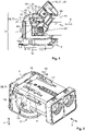
- a first advantageous embodiment of electrical plug device 1 according to the invention and an assembly according to the invention for establishing an electrical plug connection 3 comprising plug device 1 shall first be discussed with reference to Figures 1 to 5 .
- the mode of operation shall thereafter be explained with reference to Figures 6 to 11 .
- plug device 1 is used to establish an electrical plug connection to a mating connector 5.
- plug device 1 and mating connector 5 are used to establish a so-called 90° plug connection, i.e., a plugging direction 7 runs perpendicular to a lead direction 9 along which an electrical lead (not shown) of plug device 1 extends.
- Plug device 1 which can be in particular a connector, comprises a connector housing 11, a connection aid 13, and a position assurance element 15. Plug device 1 can alternatively also be a socket.
- Connector housing 11 is used to receive at least one electrical contact element (not shown) which can be arranged in particular in an interior space 17 of connector housing 11. Interior space 17 is indicated in Figure 7 .
- Connector housing 11 is configured to be plugged together with a mating housing 19 of the mating connector.
- Connector housing 11 and mating housing 19 are preferably configured in such a way that they can be plugged together along plugging direction 7.
- Plug device 1 comprises connection aid 13 to facilitate plugging the connector housing and the mating housing together, Connection aid 13 forms a drive device 21 for the plugging motion and is configured as a lever 23 held to be rotatable at connector housing 11.
- Connection aid 13 can be made to engage with mating housing 19 in order to draw mating housing 19 towards connector housing 11 and to hold mating housing 19 on connector housing 11.
- connection aid 13 can be moved from a plugging position 25 to a holding position 27, wherein connector housing 11 in plugging position 25 is connectable to mating housing 19 and mating housing 19 in holding position 27 is held at connector housing 11.
- Plugging position 25 is indicated in Figure 1 , where part of connection aid 13 is shown in dashed lines.
- Figure 1 shows connection aid 13 in a position between plugging position 25 and holding position 27.
- Holding position 27 is shown in Figures 8 to 11 .
- Position assurance element 15 is used to fixate connection aid 13 in holding position 27 at connector housing 11. Position assurance element 15 is held to be displaceable on an outer side 29 of connector housing 11.
- Position assurance element 15 can be displaced from an open position 31 to a securing position 33.
- Connection aid 13 in open position 31 can be moved from plugging position 25 to holding position 27, i.e. is not prevented from moving. In securing position 33, however, connection aid 13 is fixated in holding position 27 at connector housing 11.
- a blocking mechanism 35 is provided by way of which position assurance element 15 is blocked in open position 31 and which comprises at least one release element 37 with which blocking mechanism 35, in a state 39 of connector housing 11 and mating housing 19 being plugged together, is released.
- position assurance element 15 can be moved from open position 31 to securing position 33.
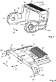
- Position assurance element 15 of the first embodiment of electrical plug device 1 shall be described in more detail hereafter, in particular with reference to Figures 4 and 5 .
- Position assurance element 15 is held to be displaceable at connector housing 11 or outer side 29 of connector housing 11, respectively, along a direction of displacement 41 which in the embodiment shown by way of example runs parallel to lead direction 9 and perpendicular to plugging direction 7.
- interior space 17 of connector housing 11 can be configured independently of position assurance element 15.
- position assurance element 15 does not penetrate into interior space 17. This makes it easier to implement a sealed connector housing 11.
- the position assurance element comprises two guide structures 47 on an underside 43, which when attached to connector housing 11 is closer to connector housing 11 than an upper side 45, which are configured to be complementary to guide structures 49 on connector housing 11.
- Guide structures 49 on connector housing 11 comprise grooves 51 which run parallel to direction of displacement 41 and are open to sides facing away from one another.
- Guide structures 47 on position assurance element 15 are provided with guide elements 53 which can engage in grooves 51.
- guide structures 49 on connector housing 11 comprise recesses 55 with which guide elements 53 can be guided transverse to direction of displacement 41 in order to connect two guide structures 47 of position assurance element 15 to two guide structures 49 of connector housing 11.
- Position assurance element 15 comprises two release elements 37 which are disposed opposite one another along a transverse direction 57 of connector housing 11.
- Transverse direction 57 runs transverse to plugging direction 7 and transverse to lead direction 9 or to direction of displacement 41, respectively.
- Two release elements 37 of the first embodiment of plug device 1 are formed as wings 59 which extend from the remainder of position assurance element 15 first a little along transverse direction 57 and thereafter in the direction toward connector housing 11. Wings 59 abut against outer side 29 and engage around connector housing 11 at least in sections.
- each wing 59 Arranged at oppositely disposed ends 61 of wings 59 are respective chamfered sections 63 which facilitate the penetration of a section of mating housing 19 between release elements 37 and connector housing 11.
- each wing 59 opens a gap 65 between itself and connector housing 11 in order to facilitate the insertion of a section of mating housing 19 between wing 59 and connector housing 11.
- Release elements 37 configured as wings 59 can be resiliently deflected away from connector housing 11.
- Each release element 37 is provided with an opening 67 which is shown as a passage opening 67 by way of example only. Instead of a passage opening 67, opening 67 can also be formed as a recess or indentation extending from underside 43 into respective wing 59.
- Connector housing 11 is provided with locking elements 69 which in open position 31 of position assurance element 15 project into openings 67 in order to hold position assurance element 15 in a positive-fit manner at least in direction of displacement 41.
- Locking elements 69 are configured as projections 71 which project outwardly from outer side 29.
- connector housing 11 could also be provided with indentations or openings into which projections of release elements 37 project in open position 31.
- Locking elements 69 and release elements 37 are both parts of blocking mechanism 35.
- assurance element 15 In order to hold position assurance element 15 also in securing position 33, assurance element 15 comprises a catch element 73 which is resiliently deflectable away from the housing and which is configured for a positive-fit connection to a mating catch element 75 on connector housing 11.
- Mating catch element 75 defines a catch receptacle 76 in which catch tab 77 can be arranged and is then in engagement with mating catch element 75.
- Catch element 73 comprises a catch tab 77 projecting on underside 43 of position assurance element 15 and a resiliently deflectable arm 79 on which catch tab 77 is arranged.
- Resiliently deflectable arm 79 is accessible from the outside so that it can be raised manually with a tool or a finger if the intention is to release position assurance element 15 from securing position 33.
- Resiliently deflectable arm 79 extends along direction of displacement 41 and is resiliently deflectable substantially along plugging direction 7. Resiliently deflectable arm 79 is preferably arranged centrally on position assurance element 15 along transverse direction 57.
- the resiliently deflectable arm is arranged in direction of displacement 41 on the side of position assurance element 15 on which wings 59 are also disposed.
- position assurance element 15 On a side which in direction of displacement 41 is disposed oppositely, position assurance element 15 is provided with a projection 81 which, in securing position 33, can be arranged at least a little way above connection aid 13 in order to hold the latter in holding position 27.
- Position assurance element 15 is provided with a viewing window 83 through which a view onto outer side 29 of housing 11 is possible. Pictograms or information represented in a different manner can then be visible on housing 11, where position assurance element 15 is able to make visible through window 83 a different pictogram that depends on position 31 or 33. It can thus be indicated, for example, in which position 31 or 33 position assurance element 15 is disposed.
- Connection aid 13 shall be briefly discussed hereafter. Reference is presently made in particular to Figure 3 .
- Connection aid 13 is configured as a lever 23 which is mounted to be rotatable at connector housing 11.
- the rotatable mounting can be effected in that the connector housing is provided with two projections 85 that are disposed opposite one another in transverse direction 57 and point away from the remainder of housing 11 and that project through passage openings 87 in connection aid 13.
- Connection aid 13 is consequently mounted at two oppositely disposed sides of connector housing 11.
- Connection aid 13 therefore comprises two arms 89 which are spaced from one another in transverse direction 57 and which are connected by way of an actuating web 91 extending parallel to transverse direction 57.
- Connector housing 11 is there arranged between two arms 89.
- actuating web 91 Provided on actuating web 91 is a recess 93 in which projection 81 of position assurance element 15 can be arranged in securing position 33 in order to hold connection aid 13 at connector housing 11 and to prevent it from moving out of securing position 33.
- connection aid 13 comprises two recesses 95 on actuating web 91 which are arranged such that recess 93 for projection 81 of position assurance element 15 is arranged, at least in transverse direction 57, between recesses 95. Recess 93 is there open upwardly in order to receive projection 81, recesses 95 are open towards connector housing 11.
- connection aid 13 In plugging position 25, which is indicated in Figure 1 , projections 97, which are arranged on an upper side 99 of connector housing 11, project into recesses 95 so that connection aid 13 cannot move freely. In order to move connection aid 13 from the plugging position to the holding position, a force must first be exerted on actuating web 91.
- connection aid 13 on each of its arms 89 comprises a tooth 101 which can be made to engage with a complementary tooth 103 (shown in Figure 8 ) to draw mating housing 19 into connector housing 11 upon actuation of connection aid 13 and to hold it thereon in the holding position.
- Mating housing 19 is provided with two continuations 105 which project from the remainder of mating housing 19 in plugging direction 7 Continuations 105 are each part of trigger elements 106 of mating housing 19. Each continuation 105 is used to release one of release elements 37. Each extension 105 has a chamfered surface 107 in order to facilitate the insertion into gap 65 between release element 37 and connector housing 11.
- each release element 37 is released from locking element 69, so that position assurance element 15 is no longer blocked in open position 31.
- Continuations 105 extend farther away from mating housing 19 along plugging direction 7 than teeth 103. Continuations 105 abut against lateral surfaces 109 of connector housing 11 and can slide therealong when connector housing 11 and mating housing 19 are plugged together.
- FIGS. 6 and 7 show a state in which connector housing 11 and mating housing 19 are already connected to one another by the actuation of connection aid 13 to such an extent that continuations 105 of mating housing 19 abut against ends 61 of wings 59. Wings 59 have not yet been raised at this point in time, and blocking mechanism 35 has therefore not yet been released. Any motion of position assurance element 15 is prevented.
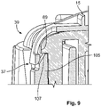
- connection aid 13 By further actuating connection aid 13 in direction of holding position 27, mating housing 19 is moved farther in plugging direction 7 and continuations 105 move into two gaps 65. As a result, two wings 59 are raised and blocking mechanism 35 is released in that locking elements 69 are no longer in engagement with wings 59. This is shown in Figures 8 and 9 .
- Position assurance element 15 can then be moved along direction of displacement 41 to securing position 33.
- projection 81 is arranged in recess 93 of the connection aid and is therefore arranged along plugging direction 7 above a section of connection aid 13.
- Connection aid 13 can now no longer be moved out of holding position 27.
- catch element 73 Since catch element 73 is in engagement with mating catch element 75 in this position, position assurance element 15 can no longer be moved out of securing position 33 as long as this engagement is not released by raising resiliently deflectable arm 79.
- position assurance element 15 can only be moved from open position 31 to securing position 33 when mating housing 19 is completely plugged together with connector housing 11, it can be prevented that connection aid 13 is moved to holding position 27 and that position assurance element 15 to securing position 33 without a completed plug connection.
- a common interior space enclosed by housings 11 and 19 is preferably sealed off from the exterior.
- at least one sealing element can be disposed between two housings 11 and 19.
- Assembly 3 and also plug device 1 of the second embodiment are configured for a 180° plug connection. This means that plugging direction 7 in this case is parallel to lead direction 9.
- Direction of displacement 41 of position assurance element 15 is also parallel to directions 7 and 9.
- Position assurance element 15 comprises no lateral wings 59 as release elements 37. Instead, position assurance element 15 is provided with a catch element 73 which comprises a resiliently deflectable arm 79 like in the first embodiment and which is provided with a catch projection 111 that is not chamfered on one side like catch tab 77 of the first embodiment, but has a rectangular cross-section when seen in transverse direction 57.
- free end 113 of resiliently deflectable arm 37 is provided with a leading chamfer 115 which is located on underside 43 of position assurance element 15. Free end 113 with leading chamfer 115 serves as a release element 37.
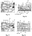
- a catch receptacle 117 configured as a recess with a rectangular cross section is provided as locking element 69 at connector housing 11, in which catch projection 111 can be held in open position 31 in a positive-fit manner in direction of displacement 41. This prevents position assurance element 15 from being displaced in open position 31 as long as blocking mechanism 35 has not been not released. This is illustrated in Figure 16 .
- a trigger element 106 in width direction 57 arranged in the middle of mating housing 19, is inserted into gap 65 between release element 37, i.e. free end 113, and the remainder of connector housing 11.
- Trigger element 106 provided as continuation 105 with a leading chamfer 119, wherein leading chamfer 119 is complementary to leading chamfer 115, raises resiliently deflectable arm 79 during the plugging process, i.e., away from connector housing 11. As a result, catch projection 111 is raised out of catch receptacle 117. This is illustrated in Figures 17 and 18 .
- connection aid 13 has reached holding position 27
- catch projection 111 is moved out of catch receptacle 117 to such an extent that blocking mechanism 35 is released and position assurance element 15 can be moved from the open position to the securing position.
- projection 81 of the position assurance element is arranged on part of connection aid 13 so that it can no longer be moved out of holding position 27.
- Connection aid 13 configured as a lever 23 can comprise a recess 93 for this purpose also in the second embodiment in which projection 81 can be received in securing position 33.
- Catch projection 111 strikes against a mating projection 121 in order to hold position assurance element 15 in securing position 33.
- Mating projection 121 can have a rectangular cross section and also define catch receptacle 117 in direction of displacement 41.
- mating projection 121 with its two sides disposed in direction of displacement 41 can define two different receptacles or recesses 117 and 123 which respectively correspond to two positions 31 and 33 of position assurance element 15.
Landscapes
- Details Of Connecting Devices For Male And Female Coupling (AREA)
- Connector Housings Or Holding Contact Members (AREA)
Abstract
Description
- The invention relates to an electrical plug device for an electrical plug connection. The invention further relates to an assembly for establishing an electrical plug connection to an electrical plug device according to the invention.
- Electrical plug devices for electrical plug connections, in particular connectors or sockets, are known. An electrical plug device generally comprises a connector housing for receiving at least one electrical contact element. The connector housing is used for being plugged together with a mating housing of a mating connector configured to be complementary. In a state when plugged together, an electrical contact element of the plug device can be electrically connected to an electrical contact element of the mating connector. In order to facilitate a plug device being plugged to a mating connector and also to secure the plug device against unintentional lease of the plug connection when plugged together with the mating connector, connection aids that form a drive device for the plugging motion are often provided and can hold the mating housing at the connector housing. In order to secure such a connection aid in a holding position in which the mating housing is held at the connector housing, position assurance elements can be used with which the connection aid in a securing position of the position assurance element is fixated in the holding position.
- The known devices are indeed useful to hold the connector and mating connector together. In particular with high-voltage connections, for example, in electrical systems of electric vehicles, it is additionally necessary to prevent the plug device and the mating connector from being plugged together incompletely or improperly. In addition, it is desirable in particular in the high-voltage sector to provide plug devices with which a sealed connection between the connector housing and the mating housing is possible.
- The above-mentioned object is satisfied for the electrical plug device in that an electrical plug connection is provided with a connector housing for receiving at least one electrical contact element, wherein the connector housing is configured to be plugged together in a plugging motion with a mating housing of a mating connector configured to be complementary to the connector housing, wherein the electrical plug device comprises at least one connection aid that is formed to be engageable with the mating housing and forms a drive device for the plugging motion between the connector housing and the mating housing, wherein the connection aid is held to be movable at the connector housing from a plugging position to a holding position, wherein the connector housing in the plugging position is connectable to the mating housing and the mating housing in the holding position is held at the connector housing, wherein the electrical plug device comprises at least one position assurance element which is held at an outer side of the connector housing to be displaceable from an open position to a securing position, wherein the connection aid in the open position of the position assurance element is movable from the plugging position to the holding position and in the securing position of the position assurance element is fixated in the holding position at the connector housing, and wherein a blocking mechanism is provided with which the position assurance element is blocked in the open position and which comprises at least one release element with which the blocking mechanism, in a state of the connector housing and the mating housing being plugged together, in particular completely, is released to displace in particular the position assurance element to the securing position.
- The solution according to the invention makes it possible for the position assurance element to be displaceable to the securing position only when the mating housing and the connector housing have been completely plugged together. The blocking mechanism is released by the connection to the mating housing and the position assurance element can be moved to the securing position in order to fixate the connection aid in the holding position. This makes it possible to rule out the possibility of the connection aid being moved to the holding position and being fixated in its securing position by the position assurance element without the mating housing being completely connected to the connector housing. This increases the safety of the connector.
- Due to the fact that the position assurance element is held to be displaceable at the outer side of the connector housing, an interior space of the connector housing can be configured independently of the position assurance element. In particular, the connector housing can be configured without openings through which the position assurance element projects into the interior space. This can facilitate establishing a sealed connection.
- The assembly according to the invention for establishing an electrical plug connection satisfies the object according to the invention in that the assembly comprises a mating connector in addition to the electrical plug device within the meaning of the invention, wherein the mating connector comprises a mating housing with at least one trigger element with which the blocking mechanism is released in a state of the connector housing and the mating housing being completely plugged together, and the position assurance element can be displaced from the open position to the securing position.
- The solution according to the invention can be further improved with various configurations that are advantageous on their own and can be combined at random. These configurations and the advantages associated therewith shall be described hereafter.
- According to a first advantageous configuration, the release element can be part of the position assurance element. The release element is preferably formed monolithically with the remainder of the position assurance element.
- The blocking mechanism is preferably configured such that the position assurance element in the open position can be locked to the outside of the connector housing, wherein the release element is resiliently deflectable by the mating housing, preferably away from the connector housing. As a result of the resilient deflection, the release element can return to its original position when it is not deflected from the mating housing.
- According to a further advantageous configuration, the blocking mechanism can comprise at least one projection and at least one receptacle, in particular a recess, for the projection, wherein the projection and the recess, or their delimitation, respectively, together form a locking mechanism through which a positive-fit connection can be established at least in a direction of displacement of the position assurance element.
- In order to prevent the loss of the position assurance element, the latter is preferably held in a captive manner at the connector housing.
- In the plugging position of the connector housing, the connector housing is open at least in sections for the connection to the mating housing or, in other words, accessible to or ready to receive the mating housing. The connection aid is preferably configured such that it holds the mating housing at the connector housing in the holding position when the mating housing in a final position is arranged relative to the connector housing. With a motion of the connection aid, the mating housing can be drawn into the connector housing, at least in sections, or pushed thereover depending on the configuration.
- In the final state mentioned above, the connector housing and the mating housing are preferably completely plugged together, the connection aid is in the holding position and the position assurance element in the securing position. In this state, the connection of the plug device and the mating connector is completed.
- The mating housing is preferably configured to receive at least one contact element which is configured for the electrical connection to a contact element arranged in the connector housing.
- The connector housing preferably has an interior space that is open for connecting to the mating housing, but that is otherwise closed to the exterior, in particular by a housing wall, and that preferably serves to receive the at least one electrical contact element. In other words, the interior space of the connector housing is preferably sealed to the exterior with the exception of a connector face. The connector housing possibly comprises cable bushings or the like, which, however, can be closed by one or more cables and/or corresponding seals.
- In order to configure an interior space of the connector housing independently of the position assurance element and in particular to obtain an interior space that is closed off from the exterior, the position assurance element preferably does not project into the interior space of the connector housing. Preferably, also no part of the connection aid projects into the interior space of the connector housing.
- In order to reliably guide the position assurance element at least from the open position to the securing position, preferably also the other way around, the connector housing preferably comprises at least one guide structure on its outer side for displaceably guiding and for holding the position assurance element. The position assurance element preferably comprises a guide structure which is configured to be complementary to the guide structure on the connector housing. The guide structures can together form a rail-like guide.
- The electrical plug device can be used for a 90° plug connection, for a 180° plug connection, or for plug connections in which a different angle is formed between the electrical conductors to be connected. In the case of a 180° plug connection, a plugging direction along which the connector housing can be plugged to the mating housing, is preferably parallel to a direction of displacement of the position assurance element. In the case of a 90° plug connection, the plugging direction is preferably transverse to the direction of displacement.
- According to a further advantageous configuration, a gap extends in the open position between the release element and the connector housing, in particular an outer side or outer wall of the connector housing, into which the mating housing, in particular a trigger element of the mating housing, can engage in order to release the blocking mechanism. The release element is preferably deflected resiliently away from the connector housing when the mating housing, in particular a trigger element of the mating housing, is inserted into the gap.
- The blocking mechanism preferably comprises at least one locking element which is arranged on the outer side of the connector housing and which is configured to hold the release element in the open position of the position assurance element in a positive-fit manner, in particular, in engagement. The locking element can therefore serve to secure the position assurance element against the displacement to the securing position. The release element and the locking element can together form a locking mechanism.
- The release element can comprise a receptacle mentioned farther above, in particular an opening or a recess, and the locking element can be formed as a projection which engages with the receptacle when the position assurance element is arranged in the open position. Alternatively, the release element can comprise a projection and the locking element can comprise a receptacle. The locking element and the release element can also have other suitable shapes, for example, catch tabs, catch noses or the like.
- The position assurance element can comprise at least one wing which projects from the remainder of the position assurance element transverse to the direction of displacement of the position assurance element and which is provided with the at least one release element. The wing itself can also form the release element. The at least one wing preferably abuts against an outer side of the connector housing and there engages in part around the connector housing. A flat configuration of the release element can thus be obtained.
- In addition, the wing can engage around the connector housing in such a way that the former can be raised from the connector housing by the mating housing, in particular by a trigger element of the mating housing, in order to release the blocking mechanism. The wing can in particular comprise an opening which extends into the wing or through the wing and into which a locking element formed as a projection arranged on the connector housing projects in the open position.
- The position assurance element preferably comprises two wings which project at two oppositely disposed sides of the position assurance element and both engage at least in part around the connector housing. The two wings preferably abut against the connector housing, provided they are not deflected by the mating housing, and can be raised resiliently therefrom at least in sections by the mating housing.
- In order to hold the position assurance element in the securing position, it can comprise at least one catch element, which is in particular resiliently deflectable away from the housing, and which is configured for a positive-fit connection to a mating catch element on the connector housing. The catch element can comprise in particular a catch tab or a catch projection on a resiliently deflectable arm.
- The catch element preferably comprises at least one catch tab or a catch projection arranged on a resiliently deflectable arm, and the mating catch element comprises at least one catch receptacle for at least part of the catch element. Alternatively, a reverse configuration is also possible.
- The catch element can be part of the release element. In other words, the release element can be used both to fixate the position assurance element in the securing position as well as in the open position. The release element can then be part of a resiliently deflectable arm which can be raised from the mating housing and which comprises at least one catch element which can be latched in at least two positions at the connector housing. There in particular in a position that defines the securing position and a position that defines the open position of the position assurance element.
- The at least one connection aid preferably comprises a lever which is mounted to be rotatable on the outer side of the connector housing and which is blocked in the securing position by the position assurance element, in particular in a positive fit. In other words, the lever in the securing position can be prevented by the position assurance element from rotating. For this purpose, the position assurance element can be arranged at least in part above the lever.
- The assembly according to the invention for establishing an electrical plug connection can be further improved in that the at least one trigger element is formed as a continuation extending in a plugging direction of the mating housing and engaging beneath the release element when the connector housing and the mating housing are in a state completely plugged together. In particular, the continuation can penetrate into a gap between the release element and the connector housing in order to raise the release element from the connector housing at least in sections.
- The connector housing and the mating housing are preferably configured to enter into a sealed connection to one another when the connector housing and the mating housing are in a state completely plugged together. For this purpose, the assembly can comprise at least one seal which is arranged between the housings at least in the state when plugged together. When plugged together, the connector housing and the mating housing can enclose a common interior space and seal it off from the outside.
- The invention shall be explained hereafter in more detail by way of example using two advantageous embodiments with reference to the drawings. The feature combinations illustrated in the embodiments by way of example can be supplemented by further features according to the above explanations in accordance with the properties of the electrical plug device of the invention that are required for a specific application. Individual features can also be omitted in the embodiments described subject to the above explanations if the effect of this feature is irrelevant for a specific case of application. The same reference numerals in the drawings are always used for elements having the same function and/or the same structure, where
- Fig. 1
- shows a perspective illustration of a first embodiment of an electrical plug device for a 90° plug connection while being plugged together;
- Fig. 2
- shows a perspective illustration of the connector housing of the plug device from
Figure 1 ; - Fig. 3
- shows the connection aid of the plug device from
Figure 1 ; - Figs. 4 and 5
- show various views of the position assurance element of the plug device from
Figure 1 ; - Figs. 6 to 11
- show the mode of operation of the electrical plug device in different steps, respectively in a perspective illustration and a sectional illustration;
- Fig. 12
- shows a second embodiment of the electrical plug device;
- Figs. 13 and 14
- show the position assurance element of the second embodiment in different views; and
- Figs. 15 to 19
- show the second embodiment of the plug device and a mating connector being plugged together.
- A first advantageous embodiment of
electrical plug device 1 according to the invention and an assembly according to the invention for establishing anelectrical plug connection 3 comprisingplug device 1 shall first be discussed with reference toFigures 1 to 5 . The mode of operation shall thereafter be explained with reference toFigures 6 to 11 . -
Electrical plug device 1, hereinafterplug device 1, is used to establish an electrical plug connection to amating connector 5. In the embodiment shown,plug device 1 andmating connector 5 are used to establish a so-called 90° plug connection, i.e., a pluggingdirection 7 runs perpendicular to alead direction 9 along which an electrical lead (not shown) ofplug device 1 extends. -
Plug device 1, which can be in particular a connector, comprises aconnector housing 11, aconnection aid 13, and aposition assurance element 15.Plug device 1 can alternatively also be a socket. -
Connector housing 11 is used to receive at least one electrical contact element (not shown) which can be arranged in particular in aninterior space 17 ofconnector housing 11.Interior space 17 is indicated inFigure 7 . -
Connector housing 11 is configured to be plugged together with amating housing 19 of the mating connector.Connector housing 11 andmating housing 19 are preferably configured in such a way that they can be plugged together along pluggingdirection 7. -
Plug device 1 comprisesconnection aid 13 to facilitate plugging the connector housing and the mating housing together,Connection aid 13 forms a drive device 21 for the plugging motion and is configured as a lever 23 held to be rotatable atconnector housing 11. -
Connection aid 13 can be made to engage withmating housing 19 in order to drawmating housing 19 towardsconnector housing 11 and to holdmating housing 19 onconnector housing 11. For this purpose,connection aid 13 can be moved from a pluggingposition 25 to a holdingposition 27, whereinconnector housing 11 in pluggingposition 25 is connectable tomating housing 19 andmating housing 19 in holdingposition 27 is held atconnector housing 11. - Plugging
position 25 is indicated inFigure 1 , where part ofconnection aid 13 is shown in dashed lines.Figure 1 showsconnection aid 13 in a position between pluggingposition 25 and holdingposition 27. Holdingposition 27 is shown inFigures 8 to 11 . -
Position assurance element 15 is used to fixateconnection aid 13 in holdingposition 27 atconnector housing 11.Position assurance element 15 is held to be displaceable on anouter side 29 ofconnector housing 11. -
Position assurance element 15 can be displaced from anopen position 31 to a securingposition 33.Connection aid 13 inopen position 31 can be moved from pluggingposition 25 to holdingposition 27, i.e. is not prevented from moving. In securingposition 33, however,connection aid 13 is fixated in holdingposition 27 atconnector housing 11. - In order to block
position assurance element 15 inopen position 31, ablocking mechanism 35 is provided by way of whichposition assurance element 15 is blocked inopen position 31 and which comprises at least onerelease element 37 with whichblocking mechanism 35, in astate 39 ofconnector housing 11 andmating housing 19 being plugged together, is released. When blockingmechanism 35 is released,position assurance element 15 can be moved fromopen position 31 to securingposition 33. -
Position assurance element 15 of the first embodiment ofelectrical plug device 1 shall be described in more detail hereafter, in particular with reference toFigures 4 and5 .Position assurance element 15 is held to be displaceable atconnector housing 11 orouter side 29 ofconnector housing 11, respectively, along a direction ofdisplacement 41 which in the embodiment shown by way of example runs parallel to leaddirection 9 and perpendicular to pluggingdirection 7. - By being held on
outer side 29,interior space 17 ofconnector housing 11 can be configured independently ofposition assurance element 15. In particular,position assurance element 15 does not penetrate intointerior space 17. This makes it easier to implement a sealedconnector housing 11. - For displaceable guidance, the position assurance element comprises two
guide structures 47 on anunderside 43, which when attached toconnector housing 11 is closer toconnector housing 11 than anupper side 45, which are configured to be complementary to guidestructures 49 onconnector housing 11. -
Guide structures 49 onconnector housing 11 comprisegrooves 51 which run parallel to direction ofdisplacement 41 and are open to sides facing away from one another.Guide structures 47 onposition assurance element 15 are provided withguide elements 53 which can engage ingrooves 51. - For connecting
position assurance element 15 toconnector housing 11, guidestructures 49 onconnector housing 11 compriserecesses 55 with which guideelements 53 can be guided transverse to direction ofdisplacement 41 in order to connect twoguide structures 47 ofposition assurance element 15 to twoguide structures 49 ofconnector housing 11. -
Position assurance element 15 comprises tworelease elements 37 which are disposed opposite one another along atransverse direction 57 ofconnector housing 11.Transverse direction 57 runs transverse to pluggingdirection 7 and transverse to leaddirection 9 or to direction ofdisplacement 41, respectively. - Two
release elements 37 of the first embodiment ofplug device 1 are formed aswings 59 which extend from the remainder ofposition assurance element 15 first a little alongtransverse direction 57 and thereafter in the direction towardconnector housing 11.Wings 59 abut againstouter side 29 and engage aroundconnector housing 11 at least in sections. - Arranged at oppositely disposed ends 61 of
wings 59 are respectivechamfered sections 63 which facilitate the penetration of a section ofmating housing 19 betweenrelease elements 37 andconnector housing 11. In other words, eachwing 59 opens agap 65 between itself andconnector housing 11 in order to facilitate the insertion of a section ofmating housing 19 betweenwing 59 andconnector housing 11. -
Release elements 37 configured aswings 59 can be resiliently deflected away fromconnector housing 11. Eachrelease element 37 is provided with anopening 67 which is shown as apassage opening 67 by way of example only. Instead of apassage opening 67, opening 67 can also be formed as a recess or indentation extending fromunderside 43 intorespective wing 59. -
Connector housing 11 is provided with lockingelements 69 which inopen position 31 ofposition assurance element 15 project intoopenings 67 in order to holdposition assurance element 15 in a positive-fit manner at least in direction ofdisplacement 41. Lockingelements 69 are configured as projections 71 which project outwardly fromouter side 29. - According to an alternative embodiment, which is not shown,
connector housing 11 could also be provided with indentations or openings into which projections ofrelease elements 37 project inopen position 31. - Locking
elements 69 and releaseelements 37 are both parts of blockingmechanism 35. - In order to hold
position assurance element 15 also in securingposition 33,assurance element 15 comprises acatch element 73 which is resiliently deflectable away from the housing and which is configured for a positive-fit connection to amating catch element 75 onconnector housing 11.Mating catch element 75 defines acatch receptacle 76 in which catchtab 77 can be arranged and is then in engagement withmating catch element 75. -
Catch element 73 comprises acatch tab 77 projecting onunderside 43 ofposition assurance element 15 and a resilientlydeflectable arm 79 on whichcatch tab 77 is arranged. Resilientlydeflectable arm 79 is accessible from the outside so that it can be raised manually with a tool or a finger if the intention is to releaseposition assurance element 15 from securingposition 33. - Resiliently
deflectable arm 79 extends along direction ofdisplacement 41 and is resiliently deflectable substantially along pluggingdirection 7. Resilientlydeflectable arm 79 is preferably arranged centrally onposition assurance element 15 alongtransverse direction 57. - The resiliently deflectable arm is arranged in direction of
displacement 41 on the side ofposition assurance element 15 on whichwings 59 are also disposed. On a side which in direction ofdisplacement 41 is disposed oppositely,position assurance element 15 is provided with aprojection 81 which, in securingposition 33, can be arranged at least a little way aboveconnection aid 13 in order to hold the latter in holdingposition 27. -
Position assurance element 15 is provided with aviewing window 83 through which a view ontoouter side 29 ofhousing 11 is possible. Pictograms or information represented in a different manner can then be visible onhousing 11, whereposition assurance element 15 is able to make visible through window 83 a different pictogram that depends onposition position position assurance element 15 is disposed. -
Connection aid 13 shall be briefly discussed hereafter. Reference is presently made in particular toFigure 3 . -
Connection aid 13 is configured as a lever 23 which is mounted to be rotatable atconnector housing 11. The rotatable mounting can be effected in that the connector housing is provided with twoprojections 85 that are disposed opposite one another intransverse direction 57 and point away from the remainder ofhousing 11 and that project throughpassage openings 87 inconnection aid 13.Connection aid 13 is consequently mounted at two oppositely disposed sides ofconnector housing 11. -
Connection aid 13 therefore comprises twoarms 89 which are spaced from one another intransverse direction 57 and which are connected by way of anactuating web 91 extending parallel totransverse direction 57.Connector housing 11 is there arranged between twoarms 89. - Provided on actuating
web 91 is arecess 93 in whichprojection 81 ofposition assurance element 15 can be arranged in securingposition 33 in order to holdconnection aid 13 atconnector housing 11 and to prevent it from moving out of securingposition 33. - In order to fixate
connection aid 13 also in the plugging position,connection aid 13 comprises tworecesses 95 on actuatingweb 91 which are arranged such thatrecess 93 forprojection 81 ofposition assurance element 15 is arranged, at least intransverse direction 57, betweenrecesses 95.Recess 93 is there open upwardly in order to receiveprojection 81, recesses 95 are open towardsconnector housing 11. - In plugging
position 25, which is indicated inFigure 1 ,projections 97, which are arranged on anupper side 99 ofconnector housing 11, project intorecesses 95 so thatconnection aid 13 cannot move freely. In order to moveconnection aid 13 from the plugging position to the holding position, a force must first be exerted on actuatingweb 91. - To facilitate plugging
connector housing 11 andmating housing 19 together,connection aid 13 on each of itsarms 89 comprises atooth 101 which can be made to engage with a complementary tooth 103 (shown inFigure 8 ) to drawmating housing 19 intoconnector housing 11 upon actuation ofconnection aid 13 and to hold it thereon in the holding position. -
Mating housing 19 is provided with twocontinuations 105 which project from the remainder ofmating housing 19 in pluggingdirection 7Continuations 105 are each part of trigger elements 106 ofmating housing 19. Eachcontinuation 105 is used to release one ofrelease elements 37. Eachextension 105 has a chamferedsurface 107 in order to facilitate the insertion intogap 65 betweenrelease element 37 andconnector housing 11. - By being pushed into
gap 65, eachrelease element 37 is released from lockingelement 69, so thatposition assurance element 15 is no longer blocked inopen position 31.Continuations 105 extend farther away frommating housing 19 along pluggingdirection 7 thanteeth 103.Continuations 105 abut againstlateral surfaces 109 ofconnector housing 11 and can slide therealong whenconnector housing 11 andmating housing 19 are plugged together. - The process of plugging
connector housing 11 andmating housing 19 together shall be described briefly hereafter with reference toFigures 6 to 11 .Figures 6 and7 show a state in whichconnector housing 11 andmating housing 19 are already connected to one another by the actuation ofconnection aid 13 to such an extent thatcontinuations 105 ofmating housing 19 abut against ends 61 ofwings 59.Wings 59 have not yet been raised at this point in time, and blockingmechanism 35 has therefore not yet been released. Any motion ofposition assurance element 15 is prevented. - By further
actuating connection aid 13 in direction of holdingposition 27,mating housing 19 is moved farther in pluggingdirection 7 andcontinuations 105 move into twogaps 65. As a result, twowings 59 are raised andblocking mechanism 35 is released in that lockingelements 69 are no longer in engagement withwings 59. This is shown inFigures 8 and9 . -
Position assurance element 15 can then be moved along direction ofdisplacement 41 to securingposition 33. In securingposition 33,projection 81 is arranged inrecess 93 of the connection aid and is therefore arranged along pluggingdirection 7 above a section ofconnection aid 13.Connection aid 13 can now no longer be moved out of holdingposition 27. - Since
catch element 73 is in engagement withmating catch element 75 in this position,position assurance element 15 can no longer be moved out of securingposition 33 as long as this engagement is not released by raising resilientlydeflectable arm 79. - Due to the fact that
position assurance element 15 can only be moved fromopen position 31 to securingposition 33 whenmating housing 19 is completely plugged together withconnector housing 11, it can be prevented thatconnection aid 13 is moved to holdingposition 27 and thatposition assurance element 15 to securingposition 33 without a completed plug connection. - In
state 39 when plugged together, a common interior space enclosed byhousings housings - A second advantageous embodiment of an
assembly 3 according to the invention with aplug device 1 according to the invention shall be described hereafter with reference toFigures 12 to 19 . For the sake of brevity, only the differences to the first embodiment described with reference toFigures 1 to 11 shall be discussed. -
Assembly 3 and also plugdevice 1 of the second embodiment are configured for a 180° plug connection. This means that pluggingdirection 7 in this case is parallel to leaddirection 9. Direction ofdisplacement 41 ofposition assurance element 15 is also parallel todirections - Due to this orientation, which differs from the first embodiment, blocking
mechanism 35 is also configured differently than in the previous embodiment.Position assurance element 15 comprises nolateral wings 59 asrelease elements 37. Instead,position assurance element 15 is provided with acatch element 73 which comprises a resilientlydeflectable arm 79 like in the first embodiment and which is provided with acatch projection 111 that is not chamfered on one side likecatch tab 77 of the first embodiment, but has a rectangular cross-section when seen intransverse direction 57. - In addition,
free end 113 of resilientlydeflectable arm 37 is provided with a leadingchamfer 115 which is located onunderside 43 ofposition assurance element 15.Free end 113 withleading chamfer 115 serves as arelease element 37. - A
catch receptacle 117, configured as a recess with a rectangular cross section is provided as lockingelement 69 atconnector housing 11, in which catchprojection 111 can be held inopen position 31 in a positive-fit manner in direction ofdisplacement 41. This preventsposition assurance element 15 from being displaced inopen position 31 as long as blockingmechanism 35 has not been not released. This is illustrated inFigure 16 . - When
connector housing 11 andmating housing 19 are plugged together, a trigger element 106, inwidth direction 57 arranged in the middle ofmating housing 19, is inserted intogap 65 betweenrelease element 37, i.e.free end 113, and the remainder ofconnector housing 11. - Trigger element 106 provided as
continuation 105 with a leadingchamfer 119, wherein leadingchamfer 119 is complementary toleading chamfer 115, raises resilientlydeflectable arm 79 during the plugging process, i.e., away fromconnector housing 11. As a result,catch projection 111 is raised out ofcatch receptacle 117. This is illustrated inFigures 17 and 18 . - In
state 39 being completely plugged together, when alsoconnection aid 13 has reached holdingposition 27,catch projection 111 is moved out ofcatch receptacle 117 to such an extent that blockingmechanism 35 is released andposition assurance element 15 can be moved from the open position to the securing position. - In securing
position 33,projection 81 of the position assurance element is arranged on part ofconnection aid 13 so that it can no longer be moved out of holdingposition 27. -
Connection aid 13 configured as a lever 23 can comprise arecess 93 for this purpose also in the second embodiment in whichprojection 81 can be received in securingposition 33. -
Catch projection 111 strikes against amating projection 121 in order to holdposition assurance element 15 in securingposition 33.Mating projection 121 can have a rectangular cross section and also definecatch receptacle 117 in direction ofdisplacement 41. In other words,mating projection 121 with its two sides disposed in direction ofdisplacement 41 can define two different receptacles orrecesses positions position assurance element 15. -
- 1
- electrical plug device
- 3
- assembly
- 5
- mating connector
- 7
- plugging direction
- 9
- lead direction
- 11
- connector housing
- 13
- connection aid
- 15
- position assurance element
- 17
- interior space
- 19
- mating housing
- 21
- drive device
- 23
- lever
- 25
- plugging position
- 27
- holding position
- 29
- outer side
- 31
- open position
- 33
- securing position
- 35
- blocking mechanism
- 37
- release element
- 39
- state being plugged together
- 41
- direction of displacement
- 43
- underside
- 45
- upper side
- 47
- guide structure
- 49
- guide structure
- 51
- groove
- 53
- guide element
- 55
- recess
- 57
- transverse direction
- 59
- wing
- 61
- end
- 63
- chamfered section
- 65
- gap
- 67
- opening
- 69
- locking element
- 71
- projection
- 73
- catch element
- 75
- mating catch element
- 76
- catch receptacle
- 77
- catch tab
- 79
- resiliently deflectable arm
- 81
- projection
- 83
- viewing window
- 85
- projection
- 87
- opening
- 89
- arm
- 91
- actuation web
- 93
- recess
- 95
- recess
- 97
- projection
- 99
- upper side
- 101
- tooth
- 103
- tooth
- 105
- continuation
- 106
- trigger element
- 107
- chamfered surface
- 109
- lateral surface
- 111
- catch projection
- 113
- free end
- 115
- leading chamfer
- 117
- catch receptacle
- 119
- leading chamfer
- 121
- mating projection
- 123
- catch receptacle
Claims (15)
- Electrical plug device (1) for an electrical plug connection with a connector housing (11) for receiving at least one electrical contact element, wherein said connector housing (11) is configured to be plugged together in a plugging motion with a mating housing (19) of a mating connector (5) configured to be complementary to said connector housing (11),wherein said electrical plug device (1) comprises at least one connection aid (13) that is formed to be engageable with said mating housing (19) and that forms a drive device (21) for the plugging motion between said connector housing (11) and said mating housing (19), wherein said connection aid (13) is held to be movable at said connector housing (11) from a plugging position (25) to a holding position (27),wherein said connector housing (25) in said plugging position (25) is connectable to said mating housing (19) and said mating housing (19) in said holding position (27) is held at said connector housing (11),wherein said electrical plug device (1) comprises at least one position assurance element (15) which is held at an outer side (29) of said connector housing (11) to be displaceable from an open position (31) to a securing position (33), wherein said connection aid (13) in said open position (31) of said position assurance element (15) is movable from said plugging position (25) to said holding position (27) and in said securing position (33) of said position assurance element (15) is fixated in said holding position (27) at said connector housing (11),and wherein a blocking mechanism (35) is provided with which said position assurance element (15) is blocked in said open position (31) and which comprises at least one release element (37) with which said blocking mechanism (35), in a state (39) of said connector housing (11) and said mating housing (19) being plugged together, is released.
- Electrical plug device (1) according to claim 1, wherein said connector housing (11) has an interior space (17) that is open for connecting to said mating housing (19) but is otherwise closed to the exterior.
- Electrical plug device (1) according to claim 1 or 2, wherein said position assurance element (15) does not project into said interior space (17) of said connector housing (11).
- Electrical plug device (1) according to one of the claims 1 to 3, wherein said connector housing (11) comprises at least one guide structure (49) on its outer side (29) for displaceably guiding and for holding said position assurance element (15).
- Electrical plug device (1) according to one of the claims 1 to 4, wherein said release element (37) is resiliently deflectable away from said connector housing (11).
- Electrical plug device (1) according to one of the claims 1 to 5, wherein a gap (65) extends in said open position (31) between said release element (37) and said connector housing (11) into which said mating housing (19) can engage in order to release said blocking mechanism (35).
- Electrical plug device (1) according to one of the claims 1 to 6, wherein said blocking mechanism (35) comprises a locking element (69) which is arranged on said outer side (29) of said connector housing (11) and which is configured to hold said release element (37) in said open position (31) of said position assurance element (15) in a positive-fit manner.
- Electrical plug device (1) according to one of the claims 1 to 7, wherein said position assurance element (15) comprises a wing (59) which projects from the remainder of said position assurance element (15) transverse to said direction of displacement (41) of said position assurance element (15) and which is provided with said at least one release element (37).
- Electrical plug device (1) according to one of the claims 1 to 8, wherein said position assurance element (15) comprises at least one catch element (73) which is configured for a positive-fit connection to a mating catch element (75) at said connector housing (11) in order to hold said position assurance element (15) in said securing position (33).
- Electrical plug device (1) according to claim 9, wherein said catch element (73) comprises at least one catch tab (77) arranged on a resiliently deflectable arm (79) and said mating catch element (75) comprises at least one catch receptacle (76) for said catch tab (77).
- Electrical plug device (1) according to claim 9 or 10, wherein said catch element (73) is part of said release element (37).
- Electrical plug device (1) according to one of the claims 1 to 11, wherein said at least one connection aid (13) comprises a lever (23) which is mounted to be rotatable on said outer side (29) of said connector housing (11) and which is blocked in said securing position (33) by said position assurance element (15).
- Assembly (3) for establishing an electrical plug connection to an electrical plug device (1) formed according to one of the claims 1 to 12 and with a mating connector (5), wherein said mating connector (5) comprises a mating housing (19) with at least one trigger element (106) with which said blocking mechanism (35) is released when said connector housing (11) and said mating housing (19) are in a state (39) being completely plugged together and said position assurance element (15) can be displaced from said open position (31) to said securing position (33).
- Assembly (3) for establishing an electrical plug connection according to claim 13, wherein said at least one trigger element (106) is formed as a continuation (105) extending in a plugging direction (7) of said mating housing (19) and engaging beneath said release element (37) when said connector housing (11) and said mating housing (19) are in a state (39) being completely plugged together.
- Assembly (3) for establishing an electrical plug connection according to claim 13 or 14, wherein said connector housing (11) and said mating housing (19) are configured to enter into a sealed connection when said connector housing (11) and said mating housing (19) are in a state (39) being completely plugged together.
Applications Claiming Priority (1)
| Application Number | Priority Date | Filing Date | Title |
|---|---|---|---|
| DE102020132994.6A DE102020132994A1 (en) | 2020-12-10 | 2020-12-10 | Electrical plug-in device with a locking mechanism, which can be released by a counter-housing, for a position-securing element |
Publications (2)
| Publication Number | Publication Date |
|---|---|
| EP4012847A1 true EP4012847A1 (en) | 2022-06-15 |
| EP4012847B1 EP4012847B1 (en) | 2025-12-31 |
Family
ID=78827656
Family Applications (1)
| Application Number | Title | Priority Date | Filing Date |
|---|---|---|---|
| EP21213452.2A Active EP4012847B1 (en) | 2020-12-10 | 2021-12-09 | ELECTRICAL PLUG DEVICE WITH A LOCKING MECHANISM FOR A POSITION LOCKING ELEMENT THAT CAN BE RELEASED BY A SUITABLE HOUSING |
Country Status (5)
| Country | Link |
|---|---|
| US (1) | US12046856B2 (en) |
| EP (1) | EP4012847B1 (en) |
| JP (1) | JP7301940B2 (en) |
| CN (1) | CN114628953B (en) |
| DE (1) | DE102020132994A1 (en) |
Cited By (1)
| Publication number | Priority date | Publication date | Assignee | Title |
|---|---|---|---|---|
| EP4415184A1 (en) * | 2023-02-13 | 2024-08-14 | TE Connectivity Solutions GmbH | Connector with connector position assurance |
Families Citing this family (6)
| Publication number | Priority date | Publication date | Assignee | Title |
|---|---|---|---|---|
| DE102020132994A1 (en) * | 2020-12-10 | 2022-06-15 | Te Connectivity Germany Gmbh | Electrical plug-in device with a locking mechanism, which can be released by a counter-housing, for a position-securing element |
| JP2024090866A (en) * | 2022-12-23 | 2024-07-04 | 日本圧着端子製造株式会社 | Electrical Connectors |
| DE102023105353A1 (en) * | 2023-03-03 | 2024-09-05 | Te Connectivity Solutions Gmbh | Plug-in arrangement |
| DE102023121870B3 (en) | 2023-08-16 | 2024-12-19 | Amphenol-Tuchel Electronics Gesellschaft mit beschränkter Haftung | Detachable plug connection with angled cable outlet |
| EP4726937A1 (en) * | 2024-10-11 | 2026-04-15 | Aptiv Technologies AG | Lever actuated cap design with flap lock design |
| CA242993S (en) * | 2025-02-21 | 2026-03-23 | Chongqing Qiulong Tech Co Ltd | Battery discharge connector for motorcycle |
Citations (1)
| Publication number | Priority date | Publication date | Assignee | Title |
|---|---|---|---|---|
| WO2013092174A1 (en) * | 2011-12-20 | 2013-06-27 | Delphi Connection Systems Holding France | Electrical connector with a lever and a connector position assurance (cpa) element |
Family Cites Families (21)
| Publication number | Priority date | Publication date | Assignee | Title |
|---|---|---|---|---|
| US20040192090A1 (en) * | 2003-03-28 | 2004-09-30 | Flowers Robert J. | Lever type electrical connector with CPA member |
| US7175451B2 (en) * | 2005-03-15 | 2007-02-13 | Tyco Electronics Corporation | Lever mated connector assembly with a position assurance device |
| JP2007149420A (en) * | 2005-11-25 | 2007-06-14 | Yazaki Corp | Lever fitting type connector |
| DE102007026582B3 (en) | 2007-06-08 | 2008-12-04 | Tyco Electronics Amp Gmbh | Connector housing with a fixation for an electrical contact element and an electrical line |
| DE102009027660B4 (en) | 2009-07-13 | 2015-02-05 | Tyco Electronics Amp Gmbh | Connector with a blocking element and housing with a blocking element. |
| JP5686577B2 (en) * | 2010-11-15 | 2015-03-18 | 矢崎総業株式会社 | Connector unit |
| EP2863490B1 (en) | 2013-10-18 | 2017-12-27 | Delphi International Operations Luxembourg S.à r.l. | Connector assembly with CPA member |
| KR101503507B1 (en) | 2014-04-09 | 2015-03-18 | 주식회사 경신 | Connector for vehicle |
| EP3007283B8 (en) | 2014-10-07 | 2019-02-27 | Aptiv Technologies Limited | Electrical connector mateable with a complementary mating connector |
| DE102014220893A1 (en) | 2014-10-15 | 2016-04-21 | Te Connectivity Germany Gmbh | Plug element, mating connector element and electrical connector |
| DE202014105369U1 (en) | 2014-11-10 | 2014-11-19 | Lisa Dräxlmaier GmbH | Plug for making an electrical connection with a mating connector |
| US9899761B2 (en) * | 2016-01-21 | 2018-02-20 | Te Connectivity Corporation | Connector system with connector position assurance |
| JP6920164B2 (en) * | 2017-10-05 | 2021-08-18 | タイコエレクトロニクスジャパン合同会社 | Connector and connector assembly |
| US10116095B1 (en) | 2017-10-26 | 2018-10-30 | Delphi Technologies, Inc. | Electrical connector with position assurance device |
| EP3694058B1 (en) * | 2019-02-11 | 2023-06-07 | Aptiv Technologies Limited | Connector assembly for a safety related system |
| CN209823007U (en) * | 2019-04-24 | 2019-12-20 | 珂耐特(常州)智能科技有限公司 | Straight head connector with lever handle |
| CN210156622U (en) * | 2019-06-21 | 2020-03-17 | 珂耐特(常州)智能科技有限公司 | Single-hole elbow connector with lever handle |
| DE102020202727A1 (en) | 2020-03-03 | 2021-09-09 | Te Connectivity Germany Gmbh | Housing arrangement for a plug, method for releasing a connection between a plug and a mating plug |
| GB2601164A (en) * | 2020-11-20 | 2022-05-25 | Aptiv Tech Ltd | Electrical Connector With A Lever Pre-Locking Member And Connector Release Mechanism At Pre-Mating |
| DE102020132994A1 (en) * | 2020-12-10 | 2022-06-15 | Te Connectivity Germany Gmbh | Electrical plug-in device with a locking mechanism, which can be released by a counter-housing, for a position-securing element |
| DE102022118993A1 (en) * | 2022-07-28 | 2024-02-08 | Te Connectivity Germany Gmbh | Housing arrangement for an electrical plug with a plug-in aid as well as electrical plug and plug arrangement |
-
2020
- 2020-12-10 DE DE102020132994.6A patent/DE102020132994A1/en active Pending
-
2021
- 2021-12-07 JP JP2021198211A patent/JP7301940B2/en active Active
- 2021-12-08 CN CN202111492367.6A patent/CN114628953B/en active Active
- 2021-12-09 EP EP21213452.2A patent/EP4012847B1/en active Active
- 2021-12-10 US US17/547,684 patent/US12046856B2/en active Active
Patent Citations (1)
| Publication number | Priority date | Publication date | Assignee | Title |
|---|---|---|---|---|
| WO2013092174A1 (en) * | 2011-12-20 | 2013-06-27 | Delphi Connection Systems Holding France | Electrical connector with a lever and a connector position assurance (cpa) element |
Cited By (2)
| Publication number | Priority date | Publication date | Assignee | Title |
|---|---|---|---|---|
| EP4415184A1 (en) * | 2023-02-13 | 2024-08-14 | TE Connectivity Solutions GmbH | Connector with connector position assurance |
| US12700697B2 (en) | 2023-02-13 | 2026-08-04 | Te Connectivity Solutions Gmbh | Connector with connector position assurance |
Also Published As
| Publication number | Publication date |
|---|---|
| EP4012847B1 (en) | 2025-12-31 |
| CN114628953A (en) | 2022-06-14 |
| DE102020132994A1 (en) | 2022-06-15 |
| JP2022092594A (en) | 2022-06-22 |
| US20220190520A1 (en) | 2022-06-16 |
| JP7301940B2 (en) | 2023-07-03 |
| CN114628953B (en) | 2024-03-12 |
| US12046856B2 (en) | 2024-07-23 |
Similar Documents
| Publication | Publication Date | Title |
|---|---|---|
| EP4012847B1 (en) | ELECTRICAL PLUG DEVICE WITH A LOCKING MECHANISM FOR A POSITION LOCKING ELEMENT THAT CAN BE RELEASED BY A SUITABLE HOUSING | |
| US10038278B2 (en) | Electrical connector having a connector position assurance element | |
| US6004153A (en) | Electrical connector with connector position assurance device | |
| CN112534651B (en) | Electrical connector with terminal position assurance device | |
| EP3648259B1 (en) | Electrical connector with latches and terminal position assurance projections provided on hinged cover | |
| CN103053082A (en) | Electrical connector with outer housing, inner housing and indicator sleeve | |
| KR20140047020A (en) | Plug-connector with cap-holding mechanism | |
| EP3329559B1 (en) | Electric plug connector with vibration-resistant short-circuiting bridge and electric plug connection | |
| IE57167B1 (en) | Connector having means for positively seating contacts | |
| US11942715B2 (en) | Terminal position assurance device and corresponding connector assembly | |
| JPH04218281A (en) | Electric connector | |
| CN111864472A (en) | Plug connector for an electrical plug device and assembly of a plug connector and a functional element | |
| CN117999708A (en) | Connector for flat flexible cable | |
| CN113169481B (en) | Plug connector device | |
| JP2021519491A (en) | Connector position guarantee member | |
| EP0035354A2 (en) | Zero insertion force electrical connector | |
| US5865636A (en) | Seal for use with an electrical connector comprising insulation displacement type contacts | |
| EP3082200A1 (en) | Electrical connector system with connector position assurance | |
| EP1905134B1 (en) | Electrical connector | |
| JP7427603B2 (en) | Connector position guarantee member | |
| EP3975345A1 (en) | Connector assembly comprising module with integrated terminal position assurance means | |
| CN101199087A (en) | Double Action Mechanical Auxiliary Connector | |
| EP4468525A1 (en) | Sealed connector with self locking tpa | |
| WO2015114662A1 (en) | Multi function connector positioning assurance device | |
| EP4611184A1 (en) | Connector |
Legal Events
| Date | Code | Title | Description |
|---|---|---|---|
| PUAI | Public reference made under article 153(3) epc to a published international application that has entered the european phase |
Free format text: ORIGINAL CODE: 0009012 |
|
| STAA | Information on the status of an ep patent application or granted ep patent |
Free format text: STATUS: THE APPLICATION HAS BEEN PUBLISHED |
|
| AK | Designated contracting states |
Kind code of ref document: A1 Designated state(s): AL AT BE BG CH CY CZ DE DK EE ES FI FR GB GR HR HU IE IS IT LI LT LU LV MC MK MT NL NO PL PT RO RS SE SI SK SM TR |
|
| STAA | Information on the status of an ep patent application or granted ep patent |
Free format text: STATUS: REQUEST FOR EXAMINATION WAS MADE |
|
| 17P | Request for examination filed |
Effective date: 20221212 |
|
| RBV | Designated contracting states (corrected) |
Designated state(s): AL AT BE BG CH CY CZ DE DK EE ES FI FR GB GR HR HU IE IS IT LI LT LU LV MC MK MT NL NO PL PT RO RS SE SI SK SM TR |
|
| STAA | Information on the status of an ep patent application or granted ep patent |
Free format text: STATUS: EXAMINATION IS IN PROGRESS |
|
| 17Q | First examination report despatched |
Effective date: 20240125 |
|
| GRAP | Despatch of communication of intention to grant a patent |
Free format text: ORIGINAL CODE: EPIDOSNIGR1 |
|
| STAA | Information on the status of an ep patent application or granted ep patent |
Free format text: STATUS: GRANT OF PATENT IS INTENDED |
|
| INTG | Intention to grant announced |
Effective date: 20251002 |
|
| GRAS | Grant fee paid |
Free format text: ORIGINAL CODE: EPIDOSNIGR3 |
|
| GRAA | (expected) grant |
Free format text: ORIGINAL CODE: 0009210 |
|
| STAA | Information on the status of an ep patent application or granted ep patent |
Free format text: STATUS: THE PATENT HAS BEEN GRANTED |
|
| AK | Designated contracting states |
Kind code of ref document: B1 Designated state(s): AL AT BE BG CH CY CZ DE DK EE ES FI FR GB GR HR HU IE IS IT LI LT LU LV MC MK MT NL NO PL PT RO RS SE SI SK SM TR |
|
| REG | Reference to a national code |
Ref country code: CH Ref legal event code: F10 Free format text: ST27 STATUS EVENT CODE: U-0-0-F10-F00 (AS PROVIDED BY THE NATIONAL OFFICE) Effective date: 20251231 Ref country code: GB Ref legal event code: FG4D |
|
| REG | Reference to a national code |
Ref country code: DE Ref legal event code: R096 Ref document number: 602021045383 Country of ref document: DE |
|
| REG | Reference to a national code |
Ref country code: IE Ref legal event code: FG4D |
|
| REG | Reference to a national code |
Ref country code: LT Ref legal event code: MG9D |
|
| PG25 | Lapsed in a contracting state [announced via postgrant information from national office to epo] |
Ref country code: NO Free format text: LAPSE BECAUSE OF FAILURE TO SUBMIT A TRANSLATION OF THE DESCRIPTION OR TO PAY THE FEE WITHIN THE PRESCRIBED TIME-LIMIT Effective date: 20260331 |
|
| PG25 | Lapsed in a contracting state [announced via postgrant information from national office to epo] |
Ref country code: HR Free format text: LAPSE BECAUSE OF FAILURE TO SUBMIT A TRANSLATION OF THE DESCRIPTION OR TO PAY THE FEE WITHIN THE PRESCRIBED TIME-LIMIT Effective date: 20251231 Ref country code: FI Free format text: LAPSE BECAUSE OF FAILURE TO SUBMIT A TRANSLATION OF THE DESCRIPTION OR TO PAY THE FEE WITHIN THE PRESCRIBED TIME-LIMIT Effective date: 20251231 |
|
| PG25 | Lapsed in a contracting state [announced via postgrant information from national office to epo] |
Ref country code: RS Free format text: LAPSE BECAUSE OF FAILURE TO SUBMIT A TRANSLATION OF THE DESCRIPTION OR TO PAY THE FEE WITHIN THE PRESCRIBED TIME-LIMIT Effective date: 20260331 |
|
| PG25 | Lapsed in a contracting state [announced via postgrant information from national office to epo] |
Ref country code: LV Free format text: LAPSE BECAUSE OF FAILURE TO SUBMIT A TRANSLATION OF THE DESCRIPTION OR TO PAY THE FEE WITHIN THE PRESCRIBED TIME-LIMIT Effective date: 20251231 |
|
| PG25 | Lapsed in a contracting state [announced via postgrant information from national office to epo] |
Ref country code: BG Free format text: LAPSE BECAUSE OF FAILURE TO SUBMIT A TRANSLATION OF THE DESCRIPTION OR TO PAY THE FEE WITHIN THE PRESCRIBED TIME-LIMIT Effective date: 20251231 |
|
| REG | Reference to a national code |
Ref country code: NL Ref legal event code: MP Effective date: 20251231 |
|
| REG | Reference to a national code |
Ref country code: AT Ref legal event code: MK05 Ref document number: 1874535 Country of ref document: AT Kind code of ref document: T Effective date: 20251231 |
|
| PG25 | Lapsed in a contracting state [announced via postgrant information from national office to epo] |
Ref country code: NL Free format text: LAPSE BECAUSE OF FAILURE TO SUBMIT A TRANSLATION OF THE DESCRIPTION OR TO PAY THE FEE WITHIN THE PRESCRIBED TIME-LIMIT Effective date: 20251231 |
|
| PG25 | Lapsed in a contracting state [announced via postgrant information from national office to epo] |
Ref country code: LT Free format text: LAPSE BECAUSE OF FAILURE TO SUBMIT A TRANSLATION OF THE DESCRIPTION OR TO PAY THE FEE WITHIN THE PRESCRIBED TIME-LIMIT Effective date: 20251231 |
|
| PG25 | Lapsed in a contracting state [announced via postgrant information from national office to epo] |
Ref country code: SM Free format text: LAPSE BECAUSE OF FAILURE TO SUBMIT A TRANSLATION OF THE DESCRIPTION OR TO PAY THE FEE WITHIN THE PRESCRIBED TIME-LIMIT Effective date: 20251231 |
|
| PG25 | Lapsed in a contracting state [announced via postgrant information from national office to epo] |
Ref country code: ES Free format text: LAPSE BECAUSE OF FAILURE TO SUBMIT A TRANSLATION OF THE DESCRIPTION OR TO PAY THE FEE WITHIN THE PRESCRIBED TIME-LIMIT Effective date: 20251231 |
|
| PG25 | Lapsed in a contracting state [announced via postgrant information from national office to epo] |
Ref country code: PL Free format text: LAPSE BECAUSE OF FAILURE TO SUBMIT A TRANSLATION OF THE DESCRIPTION OR TO PAY THE FEE WITHIN THE PRESCRIBED TIME-LIMIT Effective date: 20251231 |
|
| PG25 | Lapsed in a contracting state [announced via postgrant information from national office to epo] |
Ref country code: AT Free format text: LAPSE BECAUSE OF FAILURE TO SUBMIT A TRANSLATION OF THE DESCRIPTION OR TO PAY THE FEE WITHIN THE PRESCRIBED TIME-LIMIT Effective date: 20251231 |
|
| PG25 | Lapsed in a contracting state [announced via postgrant information from national office to epo] |
Ref country code: EE Free format text: LAPSE BECAUSE OF FAILURE TO SUBMIT A TRANSLATION OF THE DESCRIPTION OR TO PAY THE FEE WITHIN THE PRESCRIBED TIME-LIMIT Effective date: 20251231 |
|
| PG25 | Lapsed in a contracting state [announced via postgrant information from national office to epo] |
Ref country code: IS Free format text: LAPSE BECAUSE OF FAILURE TO SUBMIT A TRANSLATION OF THE DESCRIPTION OR TO PAY THE FEE WITHIN THE PRESCRIBED TIME-LIMIT Effective date: 20260430 Ref country code: PT Free format text: LAPSE BECAUSE OF FAILURE TO SUBMIT A TRANSLATION OF THE DESCRIPTION OR TO PAY THE FEE WITHIN THE PRESCRIBED TIME-LIMIT Effective date: 20260430 |
|
| PG25 | Lapsed in a contracting state [announced via postgrant information from national office to epo] |
Ref country code: CZ Free format text: LAPSE BECAUSE OF FAILURE TO SUBMIT A TRANSLATION OF THE DESCRIPTION OR TO PAY THE FEE WITHIN THE PRESCRIBED TIME-LIMIT Effective date: 20251231 |
|
| PG25 | Lapsed in a contracting state [announced via postgrant information from national office to epo] |
Ref country code: SK Free format text: LAPSE BECAUSE OF FAILURE TO SUBMIT A TRANSLATION OF THE DESCRIPTION OR TO PAY THE FEE WITHIN THE PRESCRIBED TIME-LIMIT Effective date: 20251231 |
|
| PG25 | Lapsed in a contracting state [announced via postgrant information from national office to epo] |
Ref country code: SE Free format text: LAPSE BECAUSE OF FAILURE TO SUBMIT A TRANSLATION OF THE DESCRIPTION OR TO PAY THE FEE WITHIN THE PRESCRIBED TIME-LIMIT Effective date: 20251231 |