EP4012846A1 - Connector assembly - Google Patents
Connector assembly Download PDFInfo
- Publication number
- EP4012846A1 EP4012846A1 EP21203767.5A EP21203767A EP4012846A1 EP 4012846 A1 EP4012846 A1 EP 4012846A1 EP 21203767 A EP21203767 A EP 21203767A EP 4012846 A1 EP4012846 A1 EP 4012846A1
- Authority
- EP
- European Patent Office
- Prior art keywords
- detecting member
- housing
- mating
- lock
- rear direction
- Prior art date
- Legal status (The legal status is an assumption and is not a legal conclusion. Google has not performed a legal analysis and makes no representation as to the accuracy of the status listed.)
- Granted
Links
Images















Classifications
-
- H—ELECTRICITY
- H01—ELECTRIC ELEMENTS
- H01R—ELECTRICALLY-CONDUCTIVE CONNECTIONS; STRUCTURAL ASSOCIATIONS OF A PLURALITY OF MUTUALLY-INSULATED ELECTRICAL CONNECTING ELEMENTS; COUPLING DEVICES; CURRENT COLLECTORS
- H01R13/00—Details of coupling devices of the kinds covered by groups H01R12/70 or H01R24/00 - H01R33/00
- H01R13/62—Means for facilitating engagement or disengagement of coupling parts or for holding them in engagement
- H01R13/627—Snap or like fastening
- H01R13/6271—Latching means integral with the housing
- H01R13/6272—Latching means integral with the housing comprising a single latching arm
-
- H—ELECTRICITY
- H01—ELECTRIC ELEMENTS
- H01R—ELECTRICALLY-CONDUCTIVE CONNECTIONS; STRUCTURAL ASSOCIATIONS OF A PLURALITY OF MUTUALLY-INSULATED ELECTRICAL CONNECTING ELEMENTS; COUPLING DEVICES; CURRENT COLLECTORS
- H01R13/00—Details of coupling devices of the kinds covered by groups H01R12/70 or H01R24/00 - H01R33/00
- H01R13/64—Means for preventing incorrect coupling
- H01R13/641—Means for preventing incorrect coupling by indicating incorrect coupling; by indicating correct or full engagement
-
- H—ELECTRICITY
- H01—ELECTRIC ELEMENTS
- H01R—ELECTRICALLY-CONDUCTIVE CONNECTIONS; STRUCTURAL ASSOCIATIONS OF A PLURALITY OF MUTUALLY-INSULATED ELECTRICAL CONNECTING ELEMENTS; COUPLING DEVICES; CURRENT COLLECTORS
- H01R13/00—Details of coupling devices of the kinds covered by groups H01R12/70 or H01R24/00 - H01R33/00
- H01R13/46—Bases; Cases
- H01R13/502—Bases; Cases composed of different pieces
-
- H—ELECTRICITY
- H01—ELECTRIC ELEMENTS
- H01R—ELECTRICALLY-CONDUCTIVE CONNECTIONS; STRUCTURAL ASSOCIATIONS OF A PLURALITY OF MUTUALLY-INSULATED ELECTRICAL CONNECTING ELEMENTS; COUPLING DEVICES; CURRENT COLLECTORS
- H01R13/00—Details of coupling devices of the kinds covered by groups H01R12/70 or H01R24/00 - H01R33/00
- H01R13/46—Bases; Cases
- H01R13/502—Bases; Cases composed of different pieces
- H01R13/506—Bases; Cases composed of different pieces assembled by snap action of the parts
-
- H—ELECTRICITY
- H01—ELECTRIC ELEMENTS
- H01R—ELECTRICALLY-CONDUCTIVE CONNECTIONS; STRUCTURAL ASSOCIATIONS OF A PLURALITY OF MUTUALLY-INSULATED ELECTRICAL CONNECTING ELEMENTS; COUPLING DEVICES; CURRENT COLLECTORS
- H01R13/00—Details of coupling devices of the kinds covered by groups H01R12/70 or H01R24/00 - H01R33/00
- H01R13/62—Means for facilitating engagement or disengagement of coupling parts or for holding them in engagement
- H01R13/629—Additional means for facilitating engagement or disengagement of coupling parts, e.g. aligning or guiding means, levers, gas pressure electrical locking indicators, manufacturing tolerances
-
- H—ELECTRICITY
- H01—ELECTRIC ELEMENTS
- H01R—ELECTRICALLY-CONDUCTIVE CONNECTIONS; STRUCTURAL ASSOCIATIONS OF A PLURALITY OF MUTUALLY-INSULATED ELECTRICAL CONNECTING ELEMENTS; COUPLING DEVICES; CURRENT COLLECTORS
- H01R13/00—Details of coupling devices of the kinds covered by groups H01R12/70 or H01R24/00 - H01R33/00
- H01R13/62—Means for facilitating engagement or disengagement of coupling parts or for holding them in engagement
- H01R13/629—Additional means for facilitating engagement or disengagement of coupling parts, e.g. aligning or guiding means, levers, gas pressure electrical locking indicators, manufacturing tolerances
- H01R13/631—Additional means for facilitating engagement or disengagement of coupling parts, e.g. aligning or guiding means, levers, gas pressure electrical locking indicators, manufacturing tolerances for engagement only
-
- H—ELECTRICITY
- H01—ELECTRIC ELEMENTS
- H01R—ELECTRICALLY-CONDUCTIVE CONNECTIONS; STRUCTURAL ASSOCIATIONS OF A PLURALITY OF MUTUALLY-INSULATED ELECTRICAL CONNECTING ELEMENTS; COUPLING DEVICES; CURRENT COLLECTORS
- H01R13/00—Details of coupling devices of the kinds covered by groups H01R12/70 or H01R24/00 - H01R33/00
- H01R13/62—Means for facilitating engagement or disengagement of coupling parts or for holding them in engagement
- H01R13/639—Additional means for holding or locking coupling parts together, after engagement, e.g. separate keylock, retainer strap
-
- H—ELECTRICITY
- H01—ELECTRIC ELEMENTS
- H01R—ELECTRICALLY-CONDUCTIVE CONNECTIONS; STRUCTURAL ASSOCIATIONS OF A PLURALITY OF MUTUALLY-INSULATED ELECTRICAL CONNECTING ELEMENTS; COUPLING DEVICES; CURRENT COLLECTORS
- H01R24/00—Two-part coupling devices, or either of their cooperating parts, characterised by their overall structure
-
- H—ELECTRICITY
- H01—ELECTRIC ELEMENTS
- H01R—ELECTRICALLY-CONDUCTIVE CONNECTIONS; STRUCTURAL ASSOCIATIONS OF A PLURALITY OF MUTUALLY-INSULATED ELECTRICAL CONNECTING ELEMENTS; COUPLING DEVICES; CURRENT COLLECTORS
- H01R12/00—Structural associations of a plurality of mutually-insulated electrical connecting elements, specially adapted for printed circuits, e.g. printed circuit boards [PCB], flat or ribbon cables, or like generally planar structures, e.g. terminal strips, terminal blocks; Coupling devices specially adapted for printed circuits, flat or ribbon cables, or like generally planar structures; Terminals specially adapted for contact with, or insertion into, printed circuits, flat or ribbon cables, or like generally planar structures
- H01R12/70—Coupling devices
- H01R12/71—Coupling devices for rigid printing circuits or like structures
- H01R12/75—Coupling devices for rigid printing circuits or like structures connecting to cables except for flat or ribbon cables
Definitions
- This invention relates to a connector assembly comprising a first connector and a second connector with a mating detecting member.
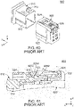
- JPB3060296 discloses a connector assembly 900 of this type.
- the connector assembly 900 comprises a first connector 910 and a second connector 920.
- the first connector 910 comprises a first housing 912.
- the first housing 912 is provided with a first lock portion 913.
- the second connector 920 comprises a second housing 922 and a positioning assurance device 926, or a mating detecting member 926.
- the second housing 922 is mateable with the first housing 912 along an X-direction.
- the second housing 922 is provided with a second lock portion 923 and a traverse piece 924.
- the second lock portion 923 is positionable at any of a lock position, which is shown in Fig.
- the second lock portion 923 has a stop wing 9232.
- the mating detecting member 926 is movable relative to the second housing 922 in the X-direction between an allowable position, which is shown in Fig. 60 , and a regulating position shown in Fig. 63 .
- the mating detecting member 926 has a stopping arm 9262 and a blocking tongue piece 9264.
- the mating detecting member 926 when the mating detecting member 926 is positioned at the allowable position, a movement of the second lock portion 923 from the lock position to the release position is allowed.
- the stopping arm 9262 of the mating detecting member 926 is positioned in a negative X-direction beyond the stop wing 9232 of the second lock portion 923 so that the mating detecting member 926 is immovable to the regulating position.
- the stopping arm 9262 of the mating detecting member 926 is positioned in a positive Z-direction beyond the stop wing 9232 of the second lock portion 923 so that the mating detecting member 926 is movable to the regulating position.
- the blocking tongue piece 9264 of the mating detecting member 926 is positioned in a negative Z-direction beyond the traverse piece 924 of the second housing 922 so that the movement of the second lock portion 923 from the lock position to the release position is regulated.
- the connector assembly 900 of Patent Document 1 is configured so that an operator can continuously perform an operation of mating the first connector 910 with the second connector 920 and an operation of moving the mating detecting member 926 by applying force to the mating detecting member 926 when the first connector 910 and the second connector 920 are mated with each other.
- an operator continuously performs the mating operation and the movement operation the operator perceives, at about the same time, two clicking sensations: a clicking sensation produced by the completion of the mating of the first connector 910 with the second connector 920; and a clicking sensation produced by a movement of the mating detecting member 926 from the allowable position to the regulating position.
- the present invention provides a connector assembly comprising a first connector and a second connector.
- the first connector comprises a first housing.
- the first housing is provided with a first lock portion and a stopper.
- the second connector comprises a second housing, a mating detecting member and a shift mechanism.
- the second housing is mateable with the first housing along a front-rear direction.
- the first housing is positioned forward of the second housing in the front-rear direction.
- the second housing is provided with a second lock portion.
- the second lock portion is positionable at any of a lock position and a release position. When the second lock portion is positioned at the lock position, the first lock portion and the second lock portion lock a mated state where the second housing is mated with the first housing.
- the mating detecting member is movable relative to the second housing in the front-rear direction between a regulating position and an allowable position.
- the allowable position is positioned rearward of the regulating position in the front-rear direction.
- a movement of the second lock portion from the lock position to the release position is regulated when the mating detecting member is positioned at the regulating position.
- the movement of the second lock portion from the lock position to the release position is allowed when the mating detecting member is positioned at the allowable position.
- the mating detecting member has an abutment portion.
- the abutment portion is movable in a direction intersecting with the front-rear direction by an operation of the shift mechanism.
- the abutment portion When the second housing starts to be mated with the first housing, the abutment portion is positioned on an imaginary line which extends in the front-rear direction and passes through the stopper.
- the second housing When the second housing is mated with the first housing under a state where the mating detecting member is positioned at the regulating position, the abutment portion abuts against the stopper, and the mating detecting member is moved from the regulating position toward the allowable position.
- the mating detecting member is positioned at the allowable position when a mating of the second housing with the first housing is completed.
- the shift mechanism When the shift mechanism is operated under a state where the mating detecting member is positioned at the allowable position, the abutment portion is moved to a position which is deviated from the imaginary line.
- the mating detecting member is moved from the allowable position to the regulating position when the mating detecting member is pushed forward in the front-rear direction under a state where the a
- the connector assembly of the present invention is configured as follows: when the second housing is mated with the first housing under the state where the mating detecting member is positioned at the regulating position, the abutment portion abuts against the stopper, and the mating detecting member is moved from the regulating position toward the allowable position; and the mating detecting member is positioned at the allowable position when the mating of the second housing with the first housing is completed. Accordingly, the connector assembly of the present invention is configured so that the mating detecting member is always moved from the allowable position to the regulating position after the mating of the second housing with the first housing is completed.
- the connector assembly of the present invention enables an operator to reliably recognize an incompletion of the mating of the second connector with the first connector upon the incompletion due to some reason.
- a connector assembly 10 comprises a first connector 100 and a second connector 200.
- the first connector 100 and the second connector 200 are mateable with each other along a front-rear direction.
- the front-rear direction is an X-direction. Specifically, it is assumed that forward is a positive X-direction while rearward is a negative X-direction.
- the first connector 100 of the present embodiment comprises a first housing 110 and first terminals 150.
- the first housing 110 of the present embodiment is made of insulator.
- the first housing 110 is provided with a socket housing accommodating portion 111, an upper surface 1112, two first lock portions 112 and two stoppers 114.
- the socket housing accommodating portion 111 of the present embodiment is a space which is opened at its rear end and extends in the front-rear direction.
- the upper surface 1112 of the present embodiment defines an upper end of the socket housing accommodating portion 111 in an up-down direction.
- the upper surface 1112 has a flat-plate shape perpendicular to the up-down direction.
- the up-down direction is a Z-direction. Specifically, upward is a positive Z-direction while downward is a negative Z-direction.
- each of the first lock portions 112 of the present embodiment is positioned around a middle of the first housing 110 in a right-left direction.
- the right-left direction is a Y-direction.
- rightward is a positive Y-direction while leftward is a negative Y-direction.
- Each of the first lock portions 112 is provided on the upper surface 1112.
- Each of the first lock portions 112 extends upward in the up-down direction from the upper surface 1112.
- Each of the first lock portions 112 extends in the front-rear direction.
- each of the first lock portions 112 has a first lock surface 1122, an upper surface 1124 and an oblique surface 1126.
- the first lock surface 1122 of the present embodiment defines a front end of the first lock portion 112 in the front-rear direction.
- the first lock surface 1122 is a plane perpendicular to the front-rear direction.
- the upper surface 1124 of the present embodiment defines an upper end of the first lock portion 112 in the up-down direction.
- the upper surface 1124 is a plane perpendicular to the up-down direction.
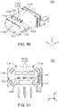
- the oblique surface 1126 of the present embodiment is positioned rearward of the upper surface 1124 in the front-rear direction. As shown in Fig. 56 , the oblique surface 1126 is a plane oblique to the front-rear direction. The oblique surface 1126 extends forward and upward.
- each of the stoppers 114 of the present embodiment is provided on the upper surface 1112.
- the stoppers 114 correspond to the first lock portions 112, respectively, and each of the stoppers 114 is positioned outward in the right-left direction beyond the first lock portion 112 corresponding thereto.
- each of the stoppers 114 extends upward in the up-down direction from the upper surface 1112.
- Each of the stoppers 114 extends in the front-rear direction.
- each of the first terminals 150 of the present embodiment is made of metal.
- Each of the first terminals 150 is a so-called pin contact.
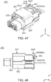
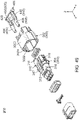
- the second connector 200 of the present embodiment comprises a second housing 300, a mating detecting member 400, a shift mechanism 500 and second terminals 250.
- the second housing 300 of the present embodiment is mateable along the front-rear direction with the first housing 110 which is positioned forward of the second housing 300 in the front-rear direction.
- the second housing 300 consists of a shroud cover 302 and a socket housing 304.
- the shroud cover 302 of the present embodiment has a first housing accommodating portion 3022, a top plate 3023, a preventing portion 3024, guiding portions 330, two protrusions 340, two resilient portions 360 and two hole portions 370.
- the second housing 300 is provided with the guiding portions 330.
- the first housing accommodating portion 3022 of the present embodiment is a space which is opened at its front end and extends in the front-rear direction.
- the top plate 3023 of the present embodiment defines an upper end of the shroud cover 302.
- the top plate 3023 has a flat-plate shape perpendicular to the up-down direction.
- the preventing portion 3024 of the present embodiment is positioned above the first housing accommodating portion 3022 in the up-down direction.
- the preventing portion 3024 is a part of the top plate 3023.
- each of the guiding portions 330 of the present embodiment is a guide rail extending in the front-rear direction.
- Each of the guiding portions 330 is opened at a rear end of the shroud cover 302.
- each of the protrusions 340 of the present embodiment protrudes outward in the right-left direction.
- the protrusions 340 correspond to the resilient portions 360, respectively.
- Each of the protrusions 340 protrudes outward in the right-left direction from the resilient portion 360 corresponding thereto.
- Each of the protrusions 340 has a retaining portion 350 and a slope portion 355. In other words, the second housing 300 has the retaining portions 350.
- each of the retaining portions 350 of the present embodiment is positioned at a rear part of the shroud cover 302.
- the retaining portion 350 defines a front end of the protrusion 340 in the front-rear direction.
- the retaining portion 350 is a plane perpendicular to the front-rear direction,
- the slope portion 355 of the present embodiment is positioned rearward of the retaining portion 350 in the front-rear direction.
- the slope portion 355 faces rearward in the front-rear direction and outward in the right-left direction.
- the slope portion 355 extends forward in the front-rear direction and outward in the right-left direction.
- each of the resilient portions 360 of the present embodiment extends forward from the rear end of the shroud cover 302.
- Each of the resilient portions 360 is resiliently deformable. Specifically, each of the resilient portions 360 resiliently supports the protrusion 340 corresponding thereto.
- each of the hole portions 370 of the present embodiment is an elongated hole extending in the front-rear direction.
- the hole portions 370 correspond to the resilient portions 360, respectively.
- Each of the hole portions 370 is positioned inward in the right-left direction beyond the resilient portion 360 corresponding thereto.
- the resilient portion 360 is resiliently deformable and the hole portion 370 is positioned inward in the right-left direction beyond the resilient portion 360 corresponding thereto. Accordingly, the resilient portion 360 is resiliently deformable inwardly in the right-left direction so that the protrusion 340 is movable inward in the right-left direction.
- the socket housing 304 of the present embodiment is fixed to the shroud cover 302.
- the socket housing 304 is provided with a second lock portion 310.
- the second housing 300 is provided with the second lock portion 310.
- the second lock portion 310 of the present embodiment is positionable at any of a lock position LP and a release position RP.
- the second lock portion 310 is movable in the up-down direction.
- a movement direction of the second lock portion 310 may be, for example, the right-left direction.
- the second lock portion 310 should be movable in a perpendicular direction perpendicular to the front-rear direction. In other words, the movement direction of the second lock portion 310 should be the perpendicular direction.
- the second lock portion 310 is positioned at the lock position LP when in its initial state. Referring to Figs. 15 and 20 , when the second lock portion 310 is positioned at the lock position LP, the first lock portions 112 and the second lock portion 310 lock a mated state where the second housing 300 is mated with the first housing 110.
- the second lock portion 310 has a locking lug 312, a release operation portion 314 and a resilient supporting portion 317.
- the locking lug 312 of the present embodiment is positioned at a front end of the second lock portion 310 in the front-rear direction. Referring to Figs. 20 and 40 , a position of the locking lug 312 upon the second lock portion 310 being at the lock position LP is positioned below a position of the locking lug 312 upon the second lock portion 310 being at the release position RP.
- the locking lug 312 has second lock surfaces 3122, a lower surface 3124 and a front end 3126.
- each of the second lock surfaces 3122 of the present embodiment is a surface facing rearward in the front-rear direction.
- the second lock surface 3122 defines a rear end of the locking lug 312 in the front-rear direction.
- the lower surface 3124 of the present embodiment is a surface facing downward in the up-down direction.
- the lower surface 3124 defines a lower end of the locking lug 312 in the up-down direction.
- the front end 3126 of the present embodiment is positioned at a front end of the locking lug 312 in the front-rear direction.
- the front end 3126 is also the front end of the second lock portion 310.
- the release operation portion 314 of the present embodiment defines a rear end of the second lock portion 310.
- the locking lug 312 is moved upward in the up-down direction perpendicular to the front-rear direction so that the second lock portion 310 is moved to the release position RP. More specifically, when the release operation portion 314 is pushed down, the locking lug 312 is moved upward in the up-down direction perpendicular to the front-rear direction so that the second lock portion 310 is moved from the lock position LP to the release position RP.
- the resilient supporting portion 317 of the present embodiment extends in the front-rear direction.
- the resilient supporting portion 317 is positioned rearward of the locking lug 312 in the front-rear direction.
- the resilient supporting portion 317 is positioned forward of the release operation portion 314 in the front-rear direction.
- the resilient supporting portion 317 is resiliently deformable.
- the second lock portion 310 of the present embodiment is provided with two movement regulating projections 316.
- each of the movement regulating projections 316 of the present embodiment protrudes outward in the right-left direction.
- the movement regulating projections 316 are positioned at opposite ends, respectively, of the second lock portion 310 in the right-left direction.
- Each of the movement regulating projections 316 is positioned around the front end of the second lock portion 310 in the front-rear direction.
- Each of the movement regulating projections 316 is positioned rearward of the locking lug 312 in the front-rear direction.
- the movement regulating projections 316 protrude outward in the right-left direction from outward ends, respectively, of the resilient supporting portion 317 in the right-left direction.
- Each of the movement regulating projections 316 is positioned forward of the release operation portion 314 in the front-rear direction. When the release operation portion 314 is pushed downward, each of the movement regulating projections 316 is moved upward in the up-down direction perpendicular to the front-rear direction.
- each of the movement regulating projections 316 has an oblique surface 3162, an upper surface 3163 and a rear surface 3168.
- the oblique surface 3162 of the present embodiment is a plane intersecting with the front-rear direction.
- the oblique surface 3162 extends forward in the front-rear direction and downward in the up-down direction.
- the oblique surface 3162 faces forward and upward.
- the upper surface 3163 of the present embodiment defines an upper end of the movement regulating projection 316 in the up-down direction.
- the upper surface 3163 is a plane intersecting with the up-down direction.
- the upper surface 3163 faces upward in the up-down direction.
- the rear surface 3168 of the present embodiment defines a rear end of the movement regulating projection 316 in the front-rear direction.
- the rear surface 3168 is a plane intersecting with the front-rear direction.
- the rear surface 3168 faces rearward in the front-rear direction.
- the second lock portion 310 of the present embodiment has a fulcrum portion 318.
- the fulcrum portion 318 is positioned around a middle of the second lock portion 310 in the front-rear direction.
- the second lock portion 310 is movable in a seesaw manner with the fulcrum portion 318 acting as a fulcrum.
- the locking lug 312 is positioned forward of the fulcrum portion 318 in the front-rear direction.
- the release operation portion 314 is positioned rearward of the fulcrum portion 318 in the front-rear direction.
- Each of the movement regulating projections 316 is positioned between the fulcrum portion 318 and the locking lug 312.
- Each of the movement regulating projections 316 is nearer to the locking lug 312 than to the fulcrum portion 318.
- the mating detecting member 400 of the present embodiment is made of resin.
- the mating detecting member 400 is attached to the shroud cover 302.
- the mating detecting member 400 of the present embodiment is movable relative to the second housing 300 in the front-rear direction between a regulating position RGP and an allowable position ALP.
- the allowable position ALP is positioned rearward of the regulating position RGP in the front-rear direction.
- the mating detecting member 400 has two arm portions 405 and two projecting portions 410.
- each of the arm portions 405 of the present embodiment extends forward in the front-rear direction.
- Each of the arm portions 405 has an upper surface 406.
- the upper surface 406 faces upward in the up-down direction.
- the projecting portions 410 of the present embodiment correspond to the arm portions 405, respectively.
- Each of the projecting portions 410 is positioned at a front end of the arm portion 405 corresponding thereto.
- Each of the projecting portions 410 protrudes downward from the front end of the arm portion 405 corresponding thereto.
- each of the projecting portions 410 has an abutment portion 412, a first lower surface 413, a front slope portion 416, a rear slope portion 418 and a second lower surface 419.
- the mating detecting member 400 has the abutment portions 412.
- the abutment portion 412 of the present embodiment faces forward in the front-rear direction.
- the abutment portion 412 defines a front end of the projecting portion 410 in the front-rear direction.
- the abutment portion 412 defines a front end of the mating detecting member 400.
- the abutment portion 412 is a plane perpendicular to the front-rear direction.
- the first lower surface 413 of the present embodiment faces downward in the up-down direction.
- the first lower surface 413 defines a lower end of the projecting portion 410 in the up-down direction.
- the first lower surface 413 is a plane perpendicular to the up-down direction.
- the front slope portion 416 of the present embodiment is positioned rearward of the abutment portion 412 in the front-rear direction.
- the front slope portion 416 is positioned below the abutment portion 412 in the up-down direction.
- the front slope portion 416 is positioned forward of the first lower surface 413 in the front-rear direction.
- the front slope portion 416 is positioned above the first lower surface 413 in the up-down direction.
- the front slope portion 416 faces forward and downward.
- the front slope portion 416 extends forward and upward.
- the rear slope portion 418 of the present embodiment is positioned rearward of the abutment portion 412 in the front-rear direction.
- the rear slope portion 418 is positioned below the abutment portion 412 in the up-down direction.
- the rear slope portion 418 is positioned rearward of the first lower surface 413 in the front-rear direction.
- the rear slope portion 418 is positioned above the first lower surface 413 in the up-down direction.
- the rear slope portion 418 faces rearward and downward.
- the rear slope portion 418 extends rearward and upward.
- the second lower surface 419 of the present embodiment is positioned at the front end of the mating detecting member 400.
- the second lower surface 419 is positioned inward of the first lower surface 413 in the right-left direction.
- the second lower surface 419 faces downward in the up-down direction.
- the second lower surface 419 is a plane perpendicular to the up-down direction.
- the second lower surface 419 is positioned above the first lower surface 413 in the up-down direction.
- the mating detecting member 400 has a regulating portion 420, click protrusions 430 and retained portions 460.
- the regulating portion 420 of the present embodiment is positioned around a rear end of the mating detecting member 400 in the front-rear direction.
- the regulating portion 420 is positioned rearward of any of the arm portions 405 in the front-rear direction.
- the regulating portion 420 has a substantially plate-like shape.
- the regulating portion 420 is positioned below the release operation portion 314 in the up-down direction to regulate the pushing down of the release operation portion 314.
- a movement of the second lock portion 310 from the lock position LP to the release position RP shown in Fig. 40 is regulated when the mating detecting member 400 is positioned at the regulating position RGP.
- the regulating portion 420 is positioned rearward in the front-rear direction beyond the release operation portion 314 so that the pushing down of the release operation portion 314 is allowed. Specifically, a movement of the second lock portion 310 from the lock position LP, which is shown in Fig. 6 , to the release position RP is allowed when the mating detecting member 400 is positioned at the allowable position ALP.
- the click protrusions 430 of the present embodiment are positioned rearward of the retained portions 460, respectively, in the front-rear direction.
- Each of the click protrusions 430 has a front slope portion 432 and a rear slope portion 434.
- the front slope portion 432 of the present embodiment faces forward in the front-rear direction and inward in the right-left direction.
- the front slope portion 432 extends forward in the front-rear direction and outward in the right-left direction.
- the front slope portion 432 of each of the click protrusions 430 is positioned rearward of the retained portion 460 corresponding thereto in the front-rear direction.
- the rear slope portion 434 of the present embodiment faces rearward in the front-rear direction and inward in the right-left direction.
- the rear slope portion 434 extends rearward in the front-rear direction and outward in the right-left direction.
- the rear slope portion 434 is positioned rearward of the front slope portion 432 in the front-rear direction.
- each of the retained portions 460 of the present embodiment is positioned around a middle of the mating detecting member 400 in the front-rear direction. As shown in Fig. 50 , the retained portions 460 are positioned below the arm portions 405, respectively, in the up-down direction. Referring to Figs. 49 and 50 , each of the retained portions 460 is positioned below the regulating portion 420 in the up-down direction. As shown in Fig. 52 , each of the retained portions 460 is positioned forward of the click protrusion 430 corresponding thereto in the front-rear direction. The retained portions 460 correspond to projecting portions 410, respectively.
- Each of the retained portions 460 is positioned inward of the first lower surface 413 of the projecting portion 410 corresponding thereto in the right-left direction. Each of the retained portions 460 faces rearward in the front-rear direction. Each of the retained portions 460 is a plane perpendicular to the front-rear direction,
- the retaining portions 350 correspond to the retained portions 460, respectively, and the retaining portion 350 and the retained portion 460 corresponding thereto prevent a rearward movement of the mating detecting member 400 in the front-rear direction relative to the second housing 300 beyond the allowable position ALP.
- the mating detecting member 400 is provided with guided portions 440 and a shift operation portion 450.
- each of the guided portions 440 is an elongated protrusion extending in the front-rear direction.
- the guided portions 440 correspond to the guiding portions 330, respectively, and the guiding portion 330 and the guided portion 440 corresponding thereto guide a movement of the mating detecting member 400 between the regulating position RGP and the allowable position ALP.
- the guided portion 440 and the guiding portion 330 corresponding thereto have sizes in the up-down direction which are large enough for the guided portion 440 to be smoothly guided by the guiding portion 330 corresponding thereto.
- the second connector 200 of the present embodiment is configured so that each of the guiding portions 330 is the guide rail extending in the front-rear direction while each of the guided portions 440 is the elongated protrusion extending in the front-rear direction.
- the present invention is not limited thereto.
- the second connector 200 should be configured so that one of the guiding portion 330 and the guided portion 440 is an elongated protrusion extending in the front-rear direction while a remaining one of the guiding portion 330 and the guided portion 440 is a guide rail which extends in the front-rear direction and guides the elongated protrusion.
- the shift operation portion 450 is positioned at the rear end of the mating detecting member 400 in the front-rear direction.
- each of the abutment portions 412 is moved in the up-down direction perpendicular to the front-rear direction.
- the second connector 200 may be configured so that the abutment portion 412 is moved in a direction intersecting with the front-rear direction when the shift operation portion 450 is operated in the perpendicular direction perpendicular to the front-rear direction.
- the guiding portion 330 and the guided portion 440 corresponding thereto have the overlapping parts each extending long in the front-rear direction when the mating detecting member 400 is positioned at the regulating position RGP. Accordingly, when the mating detecting member 400 is positioned at the regulating position RGP, a rear end of the guided portion 440 is almost immovable in the up-down direction relative to the guiding portion 330 corresponding thereto, and thereby the operation of the shift operation portion 450 in the up-down direction perpendicular to the front-rear direction is regulated.
- the second connector 200 may be configured so that the operation of the shift operation portion 450 in the perpendicular direction perpendicular to the front-rear direction is regulated when the mating detecting member 400 is positioned at the regulating position RGP.
- the guiding portion 330 and the guided portion 440 corresponding thereto have the overlapping parts each extending short in the front-rear direction. Accordingly, when the mating detecting member 400 is positioned at the allowable position ALP, the rear end of the guided portion 440 is movable, to a great extent, in the up-down direction relative to the guiding portion 330 corresponding thereto, and thereby the shift operation portion 450 is operable in the up-down direction perpendicular to the front-rear direction.
- the present invention is not limited thereto.
- the second connector 200 may be configured so that the shift operation portion 450 is operable in the perpendicular direction when the mating detecting member 400 is positioned at the allowable position ALP.
- the shift operation portion 450 may be operable, for example, in the right-left direction when the mating detecting member 400 is positioned at the allowable position ALP.
- the second connector 200 is configured so that the guided portion 440 and the guiding portion 330 corresponding thereto have the sizes in the up-down direction which are large enough for the guided portion 440 to be smoothly guided by the guiding portion 330 corresponding thereto.
- the pushing down of the shift operation portion 450 only gives a slight shake to the shift operation portion 450 and hardly moves the shift operation portion 450.
- the shift operation portion 450 is movable over a large distance upon the pushing down of the shift operation portion 450.
- the shift mechanism 500 consists of the guiding portions 330, the guided portions 440 and the shift operation portion 450.
- the guiding portions 330, the guided portions 440 and the shift operation portion 450 form the shift mechanism 500.
- each of the abutment portions 412 is movable in the direction intersecting with the front-rear direction by an operation of the shift mechanism 500. More specifically, each of the abutment portions 412 is moved upward by the shift operation portion 450 of the shift mechanism 500 being pushed down.
- the mating detecting member 400 is formed with oblique surfaces 414.
- the oblique surfaces 414 correspond to the projecting portions 410, the guided portions 440, and the click protrusions 430, respectively.
- each of the oblique surfaces 414 of the present embodiment is positioned rearward of the abutment portion 412 of the projecting portion 410 corresponding thereto in the front-rear direction.
- Each of the oblique surfaces 414 is positioned inward of the guided portion 440 corresponding thereto in the right-left direction.
- Each of the oblique surfaces 414 is positioned inward of the first lower surface 413 of the projecting portion 410 corresponding thereto in the right-left direction.
- Each of the oblique surfaces 414 is positioned at a position same as a position of the click protrusion 430 corresponding thereto in the right-left direction.
- Each of the oblique surfaces 414 is positioned rearward of the second lower surface 419 of the projecting portion 410 corresponding thereto in the front-rear direction. As shown in Fig. 12 , each of the oblique surfaces 414 faces rearward and downward. Each of the oblique surfaces 414 extends rearward and upward. Each of the oblique surfaces 414 is a plane oblique to the front-rear direction.
- each of the second terminals 250 of the present embodiment is made of metal and is a so-called socket contact.
- the second terminals 250 are held by the socket housing 304.
- the second terminals 250 are connected with the first terminals 150, respectively, when the first connector 100 and the second connector 200 are mated with each other.
- the second connector 200 whose mating detecting member 400 is positioned at the regulating position RGP, is arranged rearward of the first connector 100 in the front-rear direction.
- the abutment portions 412 of the second connector 200 are positioned rearward of the stoppers 114, respectively, of the first connector 100 in the front-rear direction, and each of the abutment portions 412 faces the stopper 114 corresponding thereto in the front-rear direction.
- the abutment portion 412 is positioned on an imaginary line IL which extends in the front-rear direction and passes through the stopper 114 corresponding thereto.
- the second housing 300 is moved forward relative to the first housing 110 so as to approach the first housing 110 in the front-rear direction in this state.
- the first housing accommodating portion 3022 of the second connector 200 accommodates a part of the first housing 110 of the first connector 100 while the socket housing accommodating portion 111 of the first housing 110 of the first connector 100 accommodates a part of the socket housing 304 of the second connector 200.
- the connector assembly 10 changes its state into a mating start state shown in each of Fig. 7 to 13 .
- each of the abutment portions 412 is positioned rearward of the stopper 114 corresponding thereto in the front-rear direction and is brought into abutment with the stopper 114 corresponding thereto in the front-rear direction.
- the click protrusions 430 of the mating detecting member 400 are positioned forward in the front-rear direction beyond the retaining portions 350, respectively, of the shroud cover 302.
- the front end 3126 of the locking lug 312 of the second lock portion 310 is not in contact with any of the first lock portions 112 in the front-rear direction.
- the front end 3126 of the locking lug 312 of the second lock portion 310 is spaced rearwardly away from any of the first lock portions 112 in the front-rear direction under the mating start state.
- the second lock portion 310 is positioned away from any of the first lock portions 112 in the front-rear direction when the mating detecting member 400 is positioned at the regulating position RGP while the abutment portion 412 abuts against the stopper 114 corresponding thereto.
- the second housing 300 is moved forward relative to the first housing 110 so as to further approach the first housing 110. Then, the mating detecting member 400 is moved rearward of the second housing 300 in the front-rear direction while the front end 3126 of the locking lug 312 of the second lock portion 310 of the second connector 200 is brought into contact with the oblique surfaces 1126 (see Fig. 56 ) of the first lock portions 112 of the first connector 100 in the front-rear direction. Meanwhile, the regulating portion 420 of the mating detecting member 400 is positioned below the release operation portion 314 of the second lock portion 310, and thereby the pushing down of the release operation portion 314 is still regulated.
- the second housing 300 is moved forward relative to the first housing 110 so as to still further approach the first housing 110.
- the mating detecting member 400 is moved further rearward relative to the second housing 300 in the front-rear direction, and the front end 3126 of the locking lug 312 is lifted upward so that the resilient supporting portion 317 of the second lock portion 310 is resiliently deformed.
- the oblique surfaces 414 of the projecting portions 410 of the mating detecting member 400 abut against the oblique surfaces 3162 of the movement regulating projections 316, respectively, of the second lock portion 310 in the front-rear direction so that each of the projecting portions 410 is lifted upward.
- the second housing 300 is moved forward relative to the first housing 110 so as to yet further approach the first housing 110 under the aforementioned state where the resilient supporting portion 317 of the second lock portion 310 is resiliently deformed. Then, the lower surface 3124 of the locking lug 312 rides over the upper surfaces 1124 (see Fig. 56 ) of the first lock portions 112, and the second lower surface 419 of each of the projecting portions 410 of the mating detecting member 400 rides over the upper surface 3163 of the movement regulating projection 316 corresponding thereto of the second lock portion 310. In this state, the second housing 300 is moved forward relative to the first housing 110 so as to yet still further approach the first housing 110.
- the connector assembly 10 changes its state into a mating completion state shown in each of Figs. 14 to 20 , and the mating detecting member 400 reaches the allowable position ALP.
- the mating detecting member 400 is positioned at the allowable position ALP when the mating of the second housing 300 with the first housing 110 is completed. In other words, the mating detecting member 400 is positioned at the allowable position ALP when the mating of the second connector 200 with the first connector 100 is completed.
- the second lock portion 310 is positioned at the lock position LP under the aforementioned mating completion state. Under the mating completion state, each of the click protrusions 430 of the mating detecting member 400 is positioned rearward in the front-rear direction beyond the retaining portion 350 corresponding thereto of the shroud cover 302. Under the mating completion state, the second lock surfaces 3122 of the locking lug 312 are positioned forward of the first lock surfaces 1122 of the first lock portions 112, respectively, in the front-rear direction, and each of the second lock surfaces 3122 faces the first lock surface 1122 corresponding thereto in the front-rear direction. In other words, under the mating completion state, the first lock portions 112 and the second lock portion 310 lock the mated state where the second housing 300 is mated with the first housing 110.
- each of the retaining portions 350 is positioned rearward in the front-rear direction beyond the retained portion 460 corresponding thereto.
- the second terminals 250 of the second connector 200 are connected with the first terminals 150, respectively, of the first connector 100.
- the mating detecting member 400 is positioned at the allowable position ALP under the mating completion state.
- the regulating portion 420 is positioned rearward in the front-rear direction beyond the release operation portion 314 so that the pushing down of the release operation portion 314 is allowed.
- each of the abutment portions 412 is still positioned rearward of the stopper 114 corresponding thereto in the front-rear direction and still abuts against the stopper 114 corresponding thereto in the front-rear direction.
- the connector assembly 10 in the mating completion state is configured as follows: the mating detecting member 400 is positioned at the allowable position ALP; the second lock portion 310 is positioned at the lock position LP; and the abutment portion 412 of each of the projecting portions 410 of the mating detecting member 400 is positioned rearward in the front-rear direction beyond the rear surface 3168 of the movement regulating projection 316 corresponding thereto and faces the rear surface 3168 thereof in the front-rear direction.
- each of the abutment portions 412 abuts against the rear surface 3168 of the movement regulating projection 316 corresponding thereto from behind, and thereby the mating detecting member 400 is prevented from being moved forward relative to the second housing 300.
- the movement regulating projection 316 is positioned forward in the front-rear direction beyond the abutment portion 412 corresponding thereto to regulate a movement of the mating detecting member 400 to the regulating position RGP.
- the rear slope portion 434 (see Fig. 52 ) of the click protrusion 430 of the mating detecting member 400 is brought into contact with the retaining portion 350 corresponding thereto of the shroud cover 302.
- the resilient portion 360 (see Fig. 54 ) is resiliently deformed inward in the right-left direction, and thereby the protrusion 340 is moved inward in the right-left direction.
- the click protrusion 430 can be moved rearward beyond the retaining portion 350 corresponding thereto in the first process.
- the abutment portion 412 When the shift operation portion 450 of the mating detecting member 400 is pushed down under the aforementioned mating completion state, the abutment portion 412 is moved upward in the up-down direction to be positioned above the movement regulating projection 316 corresponding thereto, and thereby the connector assembly 10 changes its state into a regulation release state shown in each of Figs. 21 to 26 . Specifically, when the shift mechanism 500 is operated under a state where the mating detecting member 400 is positioned at the allowable position ALP, the abutment portion 412 is moved to a position which is deviated from the imaginary line IL.
- the abutment portion 412 is positioned above the rear surface 3168 of the movement regulating projection 316 corresponding thereto in the up-down direction and does not face the rear surface 3168 thereof in the front-rear direction. Accordingly, the abutment portion 412 does not abut against the movement regulating projection 316 corresponding thereto when the mating detecting member 400 is moved forward relative to the second housing 300 under the regulation release state. In other words, the movement regulating projections 316 do not prevent a forward movement of the mating detecting member 400 relative to the second housing 300 under the regulation release state.
- the regulation of the mating detecting member 400 by the movement regulating projections 316 is released when the abutment portions 412 are moved by the operation of the shift mechanism 500 under a state where the mating of the second housing 300 with the first housing 110 is completed while the second lock portion 310 is positioned at the lock position LP. Additionally, both of the abutment portion 412 and the front slope portion 416 of each of the projecting portions 410 are brought into contact with a rear slope portion 1148 of the stopper 114 corresponding thereto in the front-rear direction under the regulation release state.
- the connector assembly 10 changes its state into a mating detecting state shown in each of Figs. 27 to 32 , and the mating detecting member 400 reaches the regulating position RGP.
- the mating detecting member 400 is moved from the allowable position ALP to the regulating position RGP when the mating detecting member 400 is pushed forward in the front-rear direction under a state where the abutment portion 412 is deviated from the imaginary line IL.
- each of the click protrusions 430 of the mating detecting member 400 is positioned forward in the front-rear direction beyond the retaining portion 350 corresponding thereto of the shroud cover 302.
- each of the abutment portions 412 is positioned forward in the front-rear direction beyond the stopper 114 corresponding thereto and does not face the stopper 114 corresponding thereto in the front-rear direction.
- the regulating portion 420 is positioned below the release operation portion 314 of the second lock portion 310 to regulate the pushing down of the release operation portion 314.
- the front slope portion 432 (see Fig. 52 ) of the click protrusion 430 of the mating detecting member 400 is brought into contact with the slope portion 355 (see Fig. 54 ) of the shroud cover 302 to provide a clicking sensation to an operator of the mating detecting member 400.
- the clicking sensation enables the operator of the mating detecting member 400 to clearly perceive that the mating detecting member 400 is being moved from the allowable position ALP to the regulating position RGP.
- Behaviors of the resilient portion 360 (see Fig.
- the protrusion 340 upon the contact of the front slope portion 432 of the click protrusion 430 with the slope portion 355 of the shroud cover 302 in the second process are similar to the behaviors of the resilient portion 360 and the protrusion 340 upon the contact of the rear slope portion 434 of the click protrusion 430 with the retaining portion 350 in the first process as described above.
- the resilient portion 360 is resiliently deformed inward in the right-left direction, and thereby the protrusion 340 is moved inward in the right-left direction.
- the click protrusion 430 can be moved forward beyond the retaining portion 350 corresponding thereto in the second process.
- the connector assembly 10 might be operated in an unusual manner where the second connector 200 begins to be mated with the first connector 100 after the second connector 200, whose mating detecting member 400 is not returned to the regulating position RGP and is still positioned at the allowable position ALP, is arranged rearward of the first connector 100.
- the unusual mating operation and behaviors of the components of the connector assembly 10 upon the unusual mating operation are similar to the usual mating operation and their behaviors upon the usual mating operation except that the mating detecting member 400 is not moved relative to the second housing 300 in a process where the connector assembly 10 changes its state from a mating start state to a mating completion state.
- each of the abutment portions 412 of the mating detecting member 400 is in abutment against the stopper 114 corresponding thereto of the first housing 110 from behind as described above. Accordingly, in this case, the mating of the second housing 300 with the first housing 110 is not completed, and thereby the connector assembly 10 never changes its state into the mating completion state. In other words, the connector assembly 10 of the present embodiment is prevented from changing its state into the mating completion state while the mating detecting member 400 maintains its location at the regulating position RGP.
- the second housing 300 begins to be mated with the first housing 110 after the second connector 200, whose mating detecting member 400 is positioned at the regulating position RGP, is arranged rearward of the first connector 100. Accordingly, in the usual mating operation, the connector assembly 10 takes a usual state where the mating detecting member 400 is positioned at the regulating position RGP under the mating incompletion state where the mating of the second connector 200 with the first connector 100 is not completed.
- the unusual mating operation which is dissimilar to the usual mating operation, might be done as described above.
- the connector assembly 10 takes an unusual state where the mating detecting member 400 is still positioned at the allowable position ALP even under the mating incompletion state where the mating of the second connector 200 with the first connector 100 is not completed.
- a further description will be made below about behaviors of the components of the connector assembly 10 in the special situation where the mating detecting member 400 is moved from the allowable position ALP toward the regulating position RGP in the unusual state which is different from the usual state.
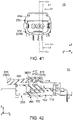
- the mating detecting member 400 is moved forward while the shift operation portion 450 is pushed down. Then, the connector assembly 10 changes its state into a movement regulating state shown in each of Figs. 41 to 44 .
- each of the movement regulating projections 316 is positioned forward in the front-rear direction beyond the abutment portion 412 corresponding thereto while the rear surface 3168 of each of the movement regulating projections 316 is in contact with the abutment portion 412 corresponding thereto in the front-rear direction.
- the mating detecting member 400 is still positioned at the allowable position ALP while the second lock portion 310 is positioned at the release position RP. Specifically, a movement of the mating detecting member 400 from the allowable position ALP to the regulating position RGP is regulated under the movement regulating state.
- each of the movement regulating projections 316 is positioned forward in the front-rear direction beyond the abutment portion 412 corresponding thereto to regulate the movement of the mating detecting member 400 to the regulating position RGP.
- the mating detecting member 400 is further moved forward under the movement regulating state. Then, the movement regulating projections 316 are pushed forward by the mating detecting member 400, and thereby the second lock portion 310 is moved forward relative to the first connector 100 together with the mating detecting member 400.
- the mating detecting member 400 is still further moved forward.
- the second lock surface 3122 reaches a position same as a position of the first lock surface 1122 corresponding thereto in the front-rear direction.
- the resilient supporting portion 317 restores its original shape, and thereby the locking lug 312 of the second lock portion 310 is moved downward.
- the second lock portion 310 is moved to the lock position LP (see Fig. 20 ) at this time.
- each of the second lock surfaces 3122 of the locking lug 312 is positioned forward in the front-rear direction beyond the first lock surface 1122 of the first lock portion 112 corresponding thereto and faces the first lock surface 1122 thereof in the front-rear direction. In other words, the mating of the second housing 300 with the first housing 110 is completed.
- the connector assembly 10 can change its state into the mating detecting state by an operation similar to the usual mating operation as described above. Specifically, the operation as follows: after the completion of the mating of the second housing 300 with the first housing 110, the mating detecting member 400 is moved forward while the shift operation portion 450 is pushed down. By the operation, the mating detecting member 400 can reach the regulating position RGP, and thereby the connector assembly 10 can change its state into the mating detecting state.
- the connector assembly 10 of the present embodiment has an advantage as follows: even if the mating detecting member 400 is erroneously moved from the allowable position ALP toward the regulating position RGP under the mating incompletion state where the mating of the second housing 300 with the first housing 110 is not completed, the mating of the second housing 300 with the first housing 110 is always completed before the mating detecting member 400 reaches the regulating position RGP.
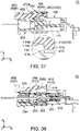
- the connector assembly 10 changes its state into a release start state shown in each of Figs. 33 to 38 .
- the release start state the rear slope portion 418 of the projecting portion 410 is in contact with a front slope portion 1146 of the stopper 114 corresponding thereto in the front-rear direction.
- the oblique surface 414 of the projecting portion 410 is still positioned forward beyond the oblique surface 3162 of the movement regulating projection 316 corresponding thereto.
- the rearward force is further applied to the mating detecting member 400 under the release start state.
- the abutment portion 412 rides over the stopper 114 corresponding thereto to be moved rearward beyond the stopper 114 corresponding thereto, while the abutment portion 412 of the projecting portion 410 passes above the movement regulating projection 316 corresponding thereto to be moved rearward beyond the movement regulating projection 316 corresponding thereto.
- the mating detecting member 400 reaches the allowable position ALP.
- the connector assembly 10 changes its state into the mating completion state shown in each of Figs. 14 to 20 .
- the second connector 200 is moved rearward relative to the first connector 100 while the second lock portion 310 is moved to the release position RP (see Fig. 40 ) by the pushing down of the release operation portion 314 of the second lock portion 310. Then, the mating of the first connector 100 with the second connector 200 is released
- the connector assembly 10 of the present embodiment is configured so that, when the mating detecting member 400 is positioned at the regulating position RGP, the movement of the second lock portion 310 from the lock position LP to the release position RP is regulated by the regulating portion 420 being positioned below the release operation portion 314 in the up-down direction to regulate the pushing down of the release operation portion 314.
- the present invention is not limited thereto.
- the connector assembly 10 may be modified so that, when the mating detecting member 400 is positioned at the regulating position RGP, the movement of the second lock portion 310 from the lock position LP to the release position RP is regulated by the regulating portion 420 being positioned above the locking lug 312 to regulate the upward movement of the locking lug 312.
- the second connector 200 of the present embodiment is configured so that the position of the locking lug 312 upon the second lock portion 310 being at the lock position LP is positioned below the position of the locking lug 312 upon the second lock portion 310 being at the release position RP.
- the present invention is not limited thereto.
- the second connector 200 may be modified so that the position of the locking lug 312 upon the second lock portion 310 being at the lock position LP is positioned above the position of the locking lug 312 upon the second lock portion 310 being at the release position RP.
- the connector assembly 10 of the present embodiment changes its state into the regulation release state by each of the abutment portions 412 being moved upward to be positioned above the movement regulating projections 316 corresponding thereto
- the present invention is not limited thereto.
- a movement direction of the abutment portion 412 is not limited, provided that the regulation of the mating detecting member 400 by the movement regulating projections 316 is released by the movement of the abutment portion 412 in the movement direction intersecting with the front-rear direction.
- the second connector 200 of the present embodiment is configured so that the click protrusions 430 and the retained portions 460 are provided on the mating detecting member 400 while the retaining portions 350 are provided on the shroud cover 302, the present invention is not limited thereto. Specifically, the reverse configuration is also possible. In other words, the second connector 200 may be modified so that the click protrusion 430 and the retained portion 460 are provided on the shroud cover 302 while the retaining portion 350 is provided on the mating detecting member 400.
Landscapes
- Details Of Connecting Devices For Male And Female Coupling (AREA)
Abstract
Description
- This invention relates to a connector assembly comprising a first connector and a second connector with a mating detecting member.
- Referring to
Figs. 60 to 63 ,JPB3060296 connector assembly 900 of this type. Theconnector assembly 900 comprises afirst connector 910 and asecond connector 920. Thefirst connector 910 comprises afirst housing 912. Thefirst housing 912 is provided with afirst lock portion 913. Thesecond connector 920 comprises asecond housing 922 and apositioning assurance device 926, or amating detecting member 926. Thesecond housing 922 is mateable with thefirst housing 912 along an X-direction. Thesecond housing 922 is provided with asecond lock portion 923 and atraverse piece 924. Thesecond lock portion 923 is positionable at any of a lock position, which is shown inFig. 63 , and a release position shown inFig. 61 . Thesecond lock portion 923 has astop wing 9232. When thesecond lock portion 923 is positioned at the lock position, thefirst lock portion 913 and thesecond lock portion 923 lock a mated state where thesecond housing 922 is mated with thefirst housing 912. Themating detecting member 926 is movable relative to thesecond housing 922 in the X-direction between an allowable position, which is shown inFig. 60 , and a regulating position shown inFig. 63 . Themating detecting member 926 has a stoppingarm 9262 and a blockingtongue piece 9264. - Referring to
Fig. 61 , when themating detecting member 926 is positioned at the allowable position, a movement of thesecond lock portion 923 from the lock position to the release position is allowed. When themating detecting member 926 is positioned at the allowable position in a middle of a mating process of thesecond housing 922 with thefirst housing 912, thestopping arm 9262 of themating detecting member 926 is positioned in a negative X-direction beyond thestop wing 9232 of thesecond lock portion 923 so that themating detecting member 926 is immovable to the regulating position. Referring toFig. 62 , when themating detecting member 926 is positioned at the allowable position under a state where the mating of thesecond housing 922 with thefirst housing 912 is completed, the stoppingarm 9262 of themating detecting member 926 is positioned in a positive Z-direction beyond thestop wing 9232 of thesecond lock portion 923 so that themating detecting member 926 is movable to the regulating position. Referring toFig. 63 , when themating detecting member 926 is positioned at the regulating position, the blockingtongue piece 9264 of themating detecting member 926 is positioned in a negative Z-direction beyond thetraverse piece 924 of thesecond housing 922 so that the movement of thesecond lock portion 923 from the lock position to the release position is regulated. - The
connector assembly 900 ofPatent Document 1 is configured so that an operator can continuously perform an operation of mating thefirst connector 910 with thesecond connector 920 and an operation of moving themating detecting member 926 by applying force to themating detecting member 926 when thefirst connector 910 and thesecond connector 920 are mated with each other. When an operator continuously performs the mating operation and the movement operation, the operator perceives, at about the same time, two clicking sensations: a clicking sensation produced by the completion of the mating of thefirst connector 910 with thesecond connector 920; and a clicking sensation produced by a movement of themating detecting member 926 from the allowable position to the regulating position. Accordingly, if there occurs a fault that themating detecting member 926 is erroneously moved from the allowable position to the regulating position under a state where the mating of thesecond connector 920 with thefirst connector 910 is not completed, an operator cannot recognize the incompletion of the mating of thesecond connector 920 with thefirst connector 910. - It is therefore an object of the present invention to provide a connector assembly which is configured so that an operation of mating a second connector with a first connector and an operation of moving a mating detecting member are independently performed and which enables an operator to reliably recognize an incompletion of the mating of the second connector with the first connector upon the incompletion due to some reason.
- One aspect of the present invention provides a connector assembly comprising a first connector and a second connector. The first connector comprises a first housing. The first housing is provided with a first lock portion and a stopper. The second connector comprises a second housing, a mating detecting member and a shift mechanism. The second housing is mateable with the first housing along a front-rear direction. The first housing is positioned forward of the second housing in the front-rear direction. The second housing is provided with a second lock portion. The second lock portion is positionable at any of a lock position and a release position. When the second lock portion is positioned at the lock position, the first lock portion and the second lock portion lock a mated state where the second housing is mated with the first housing. The mating detecting member is movable relative to the second housing in the front-rear direction between a regulating position and an allowable position. The allowable position is positioned rearward of the regulating position in the front-rear direction. A movement of the second lock portion from the lock position to the release position is regulated when the mating detecting member is positioned at the regulating position. The movement of the second lock portion from the lock position to the release position is allowed when the mating detecting member is positioned at the allowable position. The mating detecting member has an abutment portion. The abutment portion is movable in a direction intersecting with the front-rear direction by an operation of the shift mechanism. When the second housing starts to be mated with the first housing, the abutment portion is positioned on an imaginary line which extends in the front-rear direction and passes through the stopper. When the second housing is mated with the first housing under a state where the mating detecting member is positioned at the regulating position, the abutment portion abuts against the stopper, and the mating detecting member is moved from the regulating position toward the allowable position. The mating detecting member is positioned at the allowable position when a mating of the second housing with the first housing is completed. When the shift mechanism is operated under a state where the mating detecting member is positioned at the allowable position, the abutment portion is moved to a position which is deviated from the imaginary line. The mating detecting member is moved from the allowable position to the regulating position when the mating detecting member is pushed forward in the front-rear direction under a state where the abutment portion is deviated from the imaginary line.
- The connector assembly of the present invention is configured as follows: when the second housing is mated with the first housing under the state where the mating detecting member is positioned at the regulating position, the abutment portion abuts against the stopper, and the mating detecting member is moved from the regulating position toward the allowable position; and the mating detecting member is positioned at the allowable position when the mating of the second housing with the first housing is completed. Accordingly, the connector assembly of the present invention is configured so that the mating detecting member is always moved from the allowable position to the regulating position after the mating of the second housing with the first housing is completed. Specifically, an operation of mating the second connector with the first connector and an operation of moving the mating detecting member from the allowable position to the regulating position are independently performed in the connector assembly of the present invention. Thus, the connector assembly of the present invention enables an operator to reliably recognize an incompletion of the mating of the second connector with the first connector upon the incompletion due to some reason.
- An appreciation of the objectives of the present invention and a more complete understanding of its structure may be had by studying the following description of the preferred embodiment and by referring to the accompanying drawings.
-
-
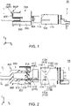
Fig. 1 is a side view showing a connector assembly according to an embodiment of the present invention. In the figure, a first connector and a second connector are not mated with each other while a mating detecting member of the second connector is positioned at a regulating position. -
Fig. 2 is a cross-sectional view showing the connector assembly ofFig. 1 , taken along line A-A. -
Fig. 3 is a top view showing the connector assembly ofFig. 1 . -
Fig. 4 is a cross-sectional view showing the connector assembly ofFig. 3 , taken along line B-B. -
Fig. 5 is a cross-sectional view showing the connector assembly ofFig. 3 , taken along line C-C. -
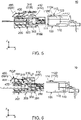
Fig. 6 is a cross-sectional view showing the connector assembly ofFig. 3 , taken along line D-D. -
Fig. 7 is another side view showing the connector assembly ofFig. 1 . In the figure, the second connector is in a middle of a mating process of being mated with the first connector while the mating detecting member is positioned at the regulating position. -
Fig. 8 is a cross-sectional view showing the connector assembly ofFig. 7 , taken along line E-E. -
Fig. 9 is a top view showing the connector assembly ofFig. 7 . -
Fig. 10 is a cross-sectional view showing the connector assembly ofFig. 9 , taken along line F-F. -
Fig. 11 is a cross-sectional view showing the connector assembly ofFig. 9 , taken along line G-G. -
Fig. 12 is a cross-sectional view showing the connector assembly ofFig. 9 , taken along line H-H. In the figure, a part of the connector assembly is illustrated enlarged. -
Fig. 13 is a cross-sectional view showing the connector assembly ofFig. 9 , taken along line I-I. -
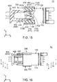
Fig. 14 is still another side view showing the connector assembly ofFig. 1 . In the figure, a first lock portion of the first connector and a second lock portion of the second connector lock a mated state where a second housing is mated with a first housing, while the mating detecting member is positioned at an allowable position. -
Fig. 15 is a cross-sectional view showing the connector assembly ofFig. 14 , taken along line J-J. -
Fig. 16 is a top view showing the connector assembly ofFig. 14 . -
Fig. 17 is a cross-sectional view showing the connector assembly ofFig. 16 , taken along line K-K. -
Fig. 18 is a cross-sectional view showing the connector assembly ofFig. 16 , taken along line L-L. -
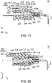
Fig. 19 is a cross-sectional view showing the connector assembly ofFig. 16 , taken along line M-M. -
Fig. 20 is a cross-sectional view showing the connector assembly ofFig. 16 , taken along line N-N. -
Fig. 21 is yet another side view showing the connector assembly ofFig. 1 . In the figure, the first lock portion of the first connector and the second lock portion of the second connector lock the mated state of the second housing with the first housing while a shift operation portion of the mating detecting member is pushed down. -
Fig. 22 is a cross-sectional view showing the connector assembly ofFig. 21 , taken along line O-O. -
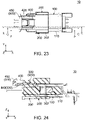
Fig. 23 is a top view showing the connector assembly ofFig. 21 . -
Fig. 24 is a cross-sectional view showing the connector assembly ofFig. 23 , taken along line P-P. -
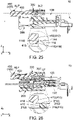
Fig. 25 is a cross-sectional view showing the connector assembly ofFig. 23 , taken along line Q-Q. In the figure, a part of the connector assembly is illustrated enlarged. -
Fig. 26 is a cross-sectional view showing the connector assembly ofFig. 23 , taken along line R-R. In the figure, a part of the connector assembly is illustrated enlarged. -
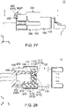
Fig. 27 is yet still another side view showing the connector assembly ofFig. 1 . In the figure, the first lock portion of the first connector and the second lock portion of the second connector lock the mated state of the second housing with the first housing while the mating detecting member is positioned at the regulating position. -
Fig. 28 is a cross-sectional view showing the connector assembly ofFig. 27 , taken along line S-S. -
Fig. 29 is a top view showing the connector assembly ofFig. 27 . -
Fig. 30 is a cross-sectional view showing the connector assembly ofFig. 29 , taken along line T-T. -
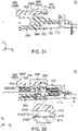
Fig. 31 is a cross-sectional view showing the connector assembly ofFig. 29 , taken along line U-U. -
Fig. 32 is a cross-sectional view showing the connector assembly ofFig. 29 , taken along line V-V. In the figure, a part of the connector assembly is illustrated enlarged. -
Fig. 33 is yet still another side view showing the connector assembly ofFig. 1 . In the figure, the first lock portion of the first connector and the second lock portion of the second connector lock the mated state of the second housing with the first housing while the mating detecting member starts to be moved from the regulating position toward the allowable position. -
Fig. 34 is a cross-sectional view showing the connector assembly ofFig. 33 , taken along line W-W. -
Fig. 35 is a top view showing the connector assembly ofFig. 33 . -
Fig. 36 is a cross-sectional view showing the connector assembly ofFig. 35 , taken along line AA-AA. -
Fig. 37 is a cross-sectional view showing the connector assembly ofFig. 35 , taken along line AB-AB. In the figure, a part of the connector assembly is illustrated enlarged. -
Fig. 38 is a cross-sectional view showing the connector assembly ofFig. 35 , taken along line AC-AC. -
Fig. 39 is a rear view showing the connector assembly ofFig. 1 . In the figure, the mating detecting member is positioned at the allowable position while the second lock portion is positioned at a release position. -
Fig. 40 is a cross-sectional view showing the connector assembly ofFig. 39 , taken along line AD-AD. In the figure, a part of the connector assembly is illustrated enlarged. -
Fig. 41 is another rear view showing the connector assembly ofFig. 1 , wherein: the second lock portion is positioned between a lock position and the release position; the first lock portion and the second lock portion do not lock the mated state of the second housing with the first housing; and the mating detecting member is positioned between the allowable position and the regulating position. -
Fig. 42 is a cross-sectional view showing the connector assembly ofFig. 41 , taken along line AE-AE. -
Fig. 43 is a cross-sectional view showing the connector assembly ofFig. 41 , taken along line AF-AF. In the figure, a part of the connector assembly is illustrated enlarged. -
Fig. 44 is a cross-sectional view showing the connector assembly ofFig. 41 , taken along line AG-AG. -
Fig. 45 is a perspective view showing the second connector which is included in the connector assembly ofFig. 1 . In the figure, the mating detecting member is positioned at the allowable position. -
Fig. 46 is a side view showing the second connector ofFig. 45 . -
Fig. 47 is another perspective view showing the second connector ofFig. 45 . In the figure, the mating detecting member is positioned at the regulating position. -
Fig. 48 is a side view showing the second connector ofFig. 47 . -
Fig. 49 is an exploded, perspective view showing the second connector ofFig. 45 . -
Fig. 50 is a perspective view showing the mating detecting member which is included in the second connector ofFig. 49 . -
Fig. 51 is a front view showing the mating detecting member ofFig. 50 . -
Fig. 52 is a bottom view showing the mating detecting member ofFig. 50 . -
Fig. 53 is a side view showing the mating detecting member ofFig. 50 . -
Fig. 54 is a top view showing a shroud cover which is included in the second connector ofFig. 49 . -
Fig. 55 is a rear, perspective view showing the shroud cover ofFig. 54 . -
Fig. 56 is a perspective view showing the first connector which is included in the connector assembly ofFig. 1 . -
Fig. 57 is a front view showing the first connector ofFig. 56 . -
Fig. 58 is a top view showing the first connector ofFig. 56 . -
Fig. 59 is a side view showing the first connector ofFig. 56 . -
Fig. 60 is a perspective view showing a connector assembly ofPatent Document 1. -
Fig. 61 is a cross-sectional view showing the connector assembly ofFig. 60 . In the figure, a first lock portion and a second lock portion do not lock a mated state where a second housing is mated with a first housing. -
Fig. 62 is another cross-sectional view showing the connector assembly ofFig. 60 . In the figure, the first lock portion and the second lock portion lock the mated state of the second housing with the first housing while a mating detecting member is positioned at an allowable position. -
Fig. 63 is still another cross-sectional view showing the connector assembly ofFig. 60 . In the figure, the first lock portion and the second lock portion lock the mated state of the second housing with the first housing while the mating detecting member is positioned at a regulating position. - While the invention is susceptible to various modifications and alternative forms, specific embodiments thereof are shown by way of example in the drawings and will herein be described in detail. It should be understood, however, that the drawings and detailed description thereto are not intended to limit the invention to the particular form disclosed, but on the contrary, the intention is to cover all modifications, equivalents and alternatives falling within the spirit and scope of the present invention as defined by the appended claims.
- As shown in
Fig. 1 , aconnector assembly 10 according to an embodiment of the present invention comprises afirst connector 100 and asecond connector 200. Thefirst connector 100 and thesecond connector 200 are mateable with each other along a front-rear direction. In the present embodiment, the front-rear direction is an X-direction. Specifically, it is assumed that forward is a positive X-direction while rearward is a negative X-direction. - As shown in
Fig. 57 , thefirst connector 100 of the present embodiment comprises afirst housing 110 andfirst terminals 150. - Referring to
Fig. 56 , thefirst housing 110 of the present embodiment is made of insulator. Thefirst housing 110 is provided with a sockethousing accommodating portion 111, anupper surface 1112, twofirst lock portions 112 and twostoppers 114. - As shown in
Fig. 56 , the sockethousing accommodating portion 111 of the present embodiment is a space which is opened at its rear end and extends in the front-rear direction. - As shown in
Fig. 56 , theupper surface 1112 of the present embodiment defines an upper end of the sockethousing accommodating portion 111 in an up-down direction. Theupper surface 1112 has a flat-plate shape perpendicular to the up-down direction. In the present embodiment, the up-down direction is a Z-direction. Specifically, upward is a positive Z-direction while downward is a negative Z-direction. - As shown in
Fig. 56 , each of thefirst lock portions 112 of the present embodiment is positioned around a middle of thefirst housing 110 in a right-left direction. In the present embodiment, the right-left direction is a Y-direction. Specifically, it is assumed that rightward is a positive Y-direction while leftward is a negative Y-direction. Each of thefirst lock portions 112 is provided on theupper surface 1112. Each of thefirst lock portions 112 extends upward in the up-down direction from theupper surface 1112. Each of thefirst lock portions 112 extends in the front-rear direction. - As shown in
Figs. 56 and58 , each of thefirst lock portions 112 has afirst lock surface 1122, anupper surface 1124 and anoblique surface 1126. - As shown in
Fig. 56 , thefirst lock surface 1122 of the present embodiment defines a front end of thefirst lock portion 112 in the front-rear direction. Thefirst lock surface 1122 is a plane perpendicular to the front-rear direction. - As shown in
Fig. 57 , theupper surface 1124 of the present embodiment defines an upper end of thefirst lock portion 112 in the up-down direction. Theupper surface 1124 is a plane perpendicular to the up-down direction. - As shown in
Fig. 58 , theoblique surface 1126 of the present embodiment is positioned rearward of theupper surface 1124 in the front-rear direction. As shown inFig. 56 , theoblique surface 1126 is a plane oblique to the front-rear direction. Theoblique surface 1126 extends forward and upward. - As shown in
Fig. 58 , each of thestoppers 114 of the present embodiment is provided on theupper surface 1112. Thestoppers 114 correspond to thefirst lock portions 112, respectively, and each of thestoppers 114 is positioned outward in the right-left direction beyond thefirst lock portion 112 corresponding thereto. As shown inFig. 56 , each of thestoppers 114 extends upward in the up-down direction from theupper surface 1112. Each of thestoppers 114 extends in the front-rear direction. - Referring to
Fig. 57 , each of thefirst terminals 150 of the present embodiment is made of metal. Each of thefirst terminals 150 is a so-called pin contact. - As shown in
Fig. 6 , thesecond connector 200 of the present embodiment comprises asecond housing 300, amating detecting member 400, ashift mechanism 500 andsecond terminals 250. - Referring to
Figs. 6 and32 , thesecond housing 300 of the present embodiment is mateable along the front-rear direction with thefirst housing 110 which is positioned forward of thesecond housing 300 in the front-rear direction. As shown inFig. 49 , thesecond housing 300 consists of ashroud cover 302 and asocket housing 304. - As shown in
Figs. 49 ,54 and 55 , theshroud cover 302 of the present embodiment has a firsthousing accommodating portion 3022, atop plate 3023, a preventingportion 3024, guidingportions 330, twoprotrusions 340, tworesilient portions 360 and twohole portions 370. In other words, thesecond housing 300 is provided with the guidingportions 330. - As shown in
Fig. 49 , the firsthousing accommodating portion 3022 of the present embodiment is a space which is opened at its front end and extends in the front-rear direction. - As shown in
Fig. 55 , thetop plate 3023 of the present embodiment defines an upper end of theshroud cover 302. Thetop plate 3023 has a flat-plate shape perpendicular to the up-down direction. - As shown in
Fig. 49 , the preventingportion 3024 of the present embodiment is positioned above the firsthousing accommodating portion 3022 in the up-down direction. The preventingportion 3024 is a part of thetop plate 3023. - As shown in
Fig. 55 , each of the guidingportions 330 of the present embodiment is a guide rail extending in the front-rear direction. Each of the guidingportions 330 is opened at a rear end of theshroud cover 302. - As shown in
Fig. 54 , each of theprotrusions 340 of the present embodiment protrudes outward in the right-left direction. Theprotrusions 340 correspond to theresilient portions 360, respectively. Each of theprotrusions 340 protrudes outward in the right-left direction from theresilient portion 360 corresponding thereto. Each of theprotrusions 340 has a retainingportion 350 and aslope portion 355. In other words, thesecond housing 300 has the retainingportions 350. - As shown in
Fig. 54 , each of the retainingportions 350 of the present embodiment is positioned at a rear part of theshroud cover 302. The retainingportion 350 defines a front end of theprotrusion 340 in the front-rear direction. The retainingportion 350 is a plane perpendicular to the front-rear direction, - As shown in
Fig. 54 , theslope portion 355 of the present embodiment is positioned rearward of the retainingportion 350 in the front-rear direction. Theslope portion 355 faces rearward in the front-rear direction and outward in the right-left direction. Theslope portion 355 extends forward in the front-rear direction and outward in the right-left direction. - As shown in
Fig. 54 , each of theresilient portions 360 of the present embodiment extends forward from the rear end of theshroud cover 302. Each of theresilient portions 360 is resiliently deformable. Specifically, each of theresilient portions 360 resiliently supports theprotrusion 340 corresponding thereto. - As shown in
Fig. 54 , each of thehole portions 370 of the present embodiment is an elongated hole extending in the front-rear direction. Thehole portions 370 correspond to theresilient portions 360, respectively. Each of thehole portions 370 is positioned inward in the right-left direction beyond theresilient portion 360 corresponding thereto. - As described above, the
resilient portion 360 is resiliently deformable and thehole portion 370 is positioned inward in the right-left direction beyond theresilient portion 360 corresponding thereto. Accordingly, theresilient portion 360 is resiliently deformable inwardly in the right-left direction so that theprotrusion 340 is movable inward in the right-left direction. - As shown in
Fig. 6 , thesocket housing 304 of the present embodiment is fixed to theshroud cover 302. As shown inFig. 49 , thesocket housing 304 is provided with asecond lock portion 310. In other words, thesecond housing 300 is provided with thesecond lock portion 310. - As shown in
Figs. 20 and40 , thesecond lock portion 310 of the present embodiment is positionable at any of a lock position LP and a release position RP. Thesecond lock portion 310 is movable in the up-down direction. However, the present invention is not limited thereto. A movement direction of thesecond lock portion 310 may be, for example, the right-left direction. Specifically, thesecond lock portion 310 should be movable in a perpendicular direction perpendicular to the front-rear direction. In other words, the movement direction of thesecond lock portion 310 should be the perpendicular direction. Thesecond lock portion 310 is positioned at the lock position LP when in its initial state. Referring toFigs. 15 and20 , when thesecond lock portion 310 is positioned at the lock position LP, thefirst lock portions 112 and thesecond lock portion 310 lock a mated state where thesecond housing 300 is mated with thefirst housing 110. - As shown in
Fig. 49 , thesecond lock portion 310 has a lockinglug 312, arelease operation portion 314 and a resilient supportingportion 317. - As shown in
Fig. 49 , the lockinglug 312 of the present embodiment is positioned at a front end of thesecond lock portion 310 in the front-rear direction. Referring toFigs. 20 and40 , a position of the lockinglug 312 upon thesecond lock portion 310 being at the lock position LP is positioned below a position of the lockinglug 312 upon thesecond lock portion 310 being at the release position RP. - As shown in
Fig. 40 , the lockinglug 312 has second lock surfaces 3122, alower surface 3124 and afront end 3126. - As shown in
Fig. 40 , each of the second lock surfaces 3122 of the present embodiment is a surface facing rearward in the front-rear direction. Thesecond lock surface 3122 defines a rear end of the lockinglug 312 in the front-rear direction. - As shown in
Fig. 40 , thelower surface 3124 of the present embodiment is a surface facing downward in the up-down direction. Thelower surface 3124 defines a lower end of the lockinglug 312 in the up-down direction. - As shown in
Fig. 40 , thefront end 3126 of the present embodiment is positioned at a front end of the lockinglug 312 in the front-rear direction. Thefront end 3126 is also the front end of thesecond lock portion 310. - As shown in
Fig. 49 , therelease operation portion 314 of the present embodiment defines a rear end of thesecond lock portion 310. Referring toFigs. 20 and40 , when therelease operation portion 314 is pushed down, the lockinglug 312 is moved upward in the up-down direction perpendicular to the front-rear direction so that thesecond lock portion 310 is moved to the release position RP. More specifically, when therelease operation portion 314 is pushed down, the lockinglug 312 is moved upward in the up-down direction perpendicular to the front-rear direction so that thesecond lock portion 310 is moved from the lock position LP to the release position RP. - As shown in
Fig. 49 , the resilient supportingportion 317 of the present embodiment extends in the front-rear direction. The resilient supportingportion 317 is positioned rearward of the lockinglug 312 in the front-rear direction. The resilient supportingportion 317 is positioned forward of therelease operation portion 314 in the front-rear direction. The resilient supportingportion 317 is resiliently deformable. - As shown in
Fig. 2 , thesecond lock portion 310 of the present embodiment is provided with twomovement regulating projections 316. - As shown in
Fig. 2 , each of themovement regulating projections 316 of the present embodiment protrudes outward in the right-left direction. Themovement regulating projections 316 are positioned at opposite ends, respectively, of thesecond lock portion 310 in the right-left direction. Each of themovement regulating projections 316 is positioned around the front end of thesecond lock portion 310 in the front-rear direction. Each of themovement regulating projections 316 is positioned rearward of the lockinglug 312 in the front-rear direction. As shown inFig. 49 , themovement regulating projections 316 protrude outward in the right-left direction from outward ends, respectively, of the resilient supportingportion 317 in the right-left direction. Each of themovement regulating projections 316 is positioned forward of therelease operation portion 314 in the front-rear direction. When therelease operation portion 314 is pushed downward, each of themovement regulating projections 316 is moved upward in the up-down direction perpendicular to the front-rear direction. - As shown in
Fig. 43 , each of themovement regulating projections 316 has anoblique surface 3162, anupper surface 3163 and arear surface 3168. - As shown in
Fig. 43 , theoblique surface 3162 of the present embodiment is a plane intersecting with the front-rear direction. Theoblique surface 3162 extends forward in the front-rear direction and downward in the up-down direction. Theoblique surface 3162 faces forward and upward. - As shown in
Fig. 43 , theupper surface 3163 of the present embodiment defines an upper end of themovement regulating projection 316 in the up-down direction. Theupper surface 3163 is a plane intersecting with the up-down direction. Theupper surface 3163 faces upward in the up-down direction. - As shown in
Fig. 43 , therear surface 3168 of the present embodiment defines a rear end of themovement regulating projection 316 in the front-rear direction. Therear surface 3168 is a plane intersecting with the front-rear direction. Therear surface 3168 faces rearward in the front-rear direction. - As shown in
Fig. 6 , thesecond lock portion 310 of the present embodiment has afulcrum portion 318. - As shown in
Fig. 13 , thefulcrum portion 318 is positioned around a middle of thesecond lock portion 310 in the front-rear direction. Referring toFigs. 13 and40 , thesecond lock portion 310 is movable in a seesaw manner with thefulcrum portion 318 acting as a fulcrum. As shown inFig. 49 , the lockinglug 312 is positioned forward of thefulcrum portion 318 in the front-rear direction. Therelease operation portion 314 is positioned rearward of thefulcrum portion 318 in the front-rear direction. Each of themovement regulating projections 316 is positioned between thefulcrum portion 318 and the lockinglug 312. Each of themovement regulating projections 316 is nearer to the lockinglug 312 than to thefulcrum portion 318. - Referring to
Fig. 49 , themating detecting member 400 of the present embodiment is made of resin. Referring toFig. 2 , themating detecting member 400 is attached to theshroud cover 302. Referring toFigs. 1 and14 , themating detecting member 400 of the present embodiment is movable relative to thesecond housing 300 in the front-rear direction between a regulating position RGP and an allowable position ALP. The allowable position ALP is positioned rearward of the regulating position RGP in the front-rear direction. - As shown in
Fig. 50 , themating detecting member 400 has twoarm portions 405 and two projectingportions 410. - As shown in
Fig. 49 , each of thearm portions 405 of the present embodiment extends forward in the front-rear direction. Each of thearm portions 405 has anupper surface 406. Theupper surface 406 faces upward in the up-down direction. - As shown in
Fig. 50 , the projectingportions 410 of the present embodiment correspond to thearm portions 405, respectively. Each of the projectingportions 410 is positioned at a front end of thearm portion 405 corresponding thereto. Each of the projectingportions 410 protrudes downward from the front end of thearm portion 405 corresponding thereto. - As shown in
Figs. 50 and52 , each of the projectingportions 410 has anabutment portion 412, a firstlower surface 413, afront slope portion 416, arear slope portion 418 and a secondlower surface 419. In other words, themating detecting member 400 has theabutment portions 412. - As shown in
Fig. 50 , theabutment portion 412 of the present embodiment faces forward in the front-rear direction. Theabutment portion 412 defines a front end of the projectingportion 410 in the front-rear direction. In other words, theabutment portion 412 defines a front end of themating detecting member 400. Theabutment portion 412 is a plane perpendicular to the front-rear direction. - As shown in
Fig. 50 , the firstlower surface 413 of the present embodiment faces downward in the up-down direction. The firstlower surface 413 defines a lower end of the projectingportion 410 in the up-down direction. The firstlower surface 413 is a plane perpendicular to the up-down direction. - As shown in
Fig. 53 , thefront slope portion 416 of the present embodiment is positioned rearward of theabutment portion 412 in the front-rear direction. Thefront slope portion 416 is positioned below theabutment portion 412 in the up-down direction. Thefront slope portion 416 is positioned forward of the firstlower surface 413 in the front-rear direction. Thefront slope portion 416 is positioned above the firstlower surface 413 in the up-down direction. Thefront slope portion 416 faces forward and downward. Thefront slope portion 416 extends forward and upward. - As shown in
Fig. 53 , therear slope portion 418 of the present embodiment is positioned rearward of theabutment portion 412 in the front-rear direction. Therear slope portion 418 is positioned below theabutment portion 412 in the up-down direction. Therear slope portion 418 is positioned rearward of the firstlower surface 413 in the front-rear direction. Therear slope portion 418 is positioned above the firstlower surface 413 in the up-down direction. Therear slope portion 418 faces rearward and downward. Therear slope portion 418 extends rearward and upward. - As shown in
Fig. 52 , the secondlower surface 419 of the present embodiment is positioned at the front end of themating detecting member 400. The secondlower surface 419 is positioned inward of the firstlower surface 413 in the right-left direction. As shown inFig. 50 , the secondlower surface 419 faces downward in the up-down direction. The secondlower surface 419 is a plane perpendicular to the up-down direction. The secondlower surface 419 is positioned above the firstlower surface 413 in the up-down direction. - As shown in
Figs. 49 and52 , themating detecting member 400 has a regulatingportion 420, clickprotrusions 430 and retainedportions 460. - As shown in
Fig. 49 , the regulatingportion 420 of the present embodiment is positioned around a rear end of themating detecting member 400 in the front-rear direction. The regulatingportion 420 is positioned rearward of any of thearm portions 405 in the front-rear direction. The regulatingportion 420 has a substantially plate-like shape. - As shown in
Fig. 6 , when themating detecting member 400 is positioned at the regulating position RGP, the regulatingportion 420 is positioned below therelease operation portion 314 in the up-down direction to regulate the pushing down of therelease operation portion 314. Specifically, a movement of thesecond lock portion 310 from the lock position LP to the release position RP shown inFig. 40 is regulated when themating detecting member 400 is positioned at the regulating position RGP. - As shown in
Fig. 40 , when themating detecting member 400 is positioned at the allowable position ALP, the regulatingportion 420 is positioned rearward in the front-rear direction beyond therelease operation portion 314 so that the pushing down of therelease operation portion 314 is allowed. Specifically, a movement of thesecond lock portion 310 from the lock position LP, which is shown inFig. 6 , to the release position RP is allowed when themating detecting member 400 is positioned at the allowable position ALP. - As shown in
Fig. 52 , theclick protrusions 430 of the present embodiment are positioned rearward of the retainedportions 460, respectively, in the front-rear direction. Each of theclick protrusions 430 has afront slope portion 432 and arear slope portion 434. - As shown in
Fig. 52 , thefront slope portion 432 of the present embodiment faces forward in the front-rear direction and inward in the right-left direction. Thefront slope portion 432 extends forward in the front-rear direction and outward in the right-left direction. Thefront slope portion 432 of each of theclick protrusions 430 is positioned rearward of the retainedportion 460 corresponding thereto in the front-rear direction. - As shown in
Fig. 52 , therear slope portion 434 of the present embodiment faces rearward in the front-rear direction and inward in the right-left direction. Therear slope portion 434 extends rearward in the front-rear direction and outward in the right-left direction. Therear slope portion 434 is positioned rearward of thefront slope portion 432 in the front-rear direction. - As shown in
Fig. 52 , each of the retainedportions 460 of the present embodiment is positioned around a middle of themating detecting member 400 in the front-rear direction. As shown inFig. 50 , the retainedportions 460 are positioned below thearm portions 405, respectively, in the up-down direction. Referring toFigs. 49 and50 , each of the retainedportions 460 is positioned below the regulatingportion 420 in the up-down direction. As shown inFig. 52 , each of the retainedportions 460 is positioned forward of theclick protrusion 430 corresponding thereto in the front-rear direction. The retainedportions 460 correspond to projectingportions 410, respectively. Each of the retainedportions 460 is positioned inward of the firstlower surface 413 of the projectingportion 410 corresponding thereto in the right-left direction. Each of the retainedportions 460 faces rearward in the front-rear direction. Each of the retainedportions 460 is a plane perpendicular to the front-rear direction, - As shown in
Fig. 19 , the retainingportions 350 correspond to the retainedportions 460, respectively, and the retainingportion 350 and the retainedportion 460 corresponding thereto prevent a rearward movement of themating detecting member 400 in the front-rear direction relative to thesecond housing 300 beyond the allowable position ALP. - As shown in
Fig. 53 , themating detecting member 400 is provided with guidedportions 440 and ashift operation portion 450. - As shown in
Fig. 50 , each of the guidedportions 440 is an elongated protrusion extending in the front-rear direction. Referring toFigs. 10 and17 , the guidedportions 440 correspond to the guidingportions 330, respectively, and the guidingportion 330 and the guidedportion 440 corresponding thereto guide a movement of themating detecting member 400 between the regulating position RGP and the allowable position ALP. The guidedportion 440 and the guidingportion 330 corresponding thereto have sizes in the up-down direction which are large enough for the guidedportion 440 to be smoothly guided by the guidingportion 330 corresponding thereto. - Referring to
Fig. 10 , when themating detecting member 400 is positioned at the regulating position RGP, almost the whole of the guidedportion 440 is accommodated in the guidingportion 330 corresponding thereto. In other words, when themating detecting member 400 is positioned at the regulating position RGP, the guidingportion 330 and the guidedportion 440 corresponding thereto have overlapping parts each extending long in the front-rear direction. Referring toFig. 17 , when themating detecting member 400 is positioned at the allowable position ALP, a greater part of the guidedportion 440 is not accommodated in the guidingportion 330 corresponding thereto and is positioned rearward beyond the guidingportion 330 corresponding thereto to be exposed to the outside of thesecond connector 200. In other words, when themating detecting member 400 is positioned at the allowable position ALP, the guidingportion 330 and the guidedportion 440 corresponding thereto have overlapping parts each extending short in the front-rear direction. - As described above, the
second connector 200 of the present embodiment is configured so that each of the guidingportions 330 is the guide rail extending in the front-rear direction while each of the guidedportions 440 is the elongated protrusion extending in the front-rear direction. However, the present invention is not limited thereto. Specifically, thesecond connector 200 should be configured so that one of the guidingportion 330 and the guidedportion 440 is an elongated protrusion extending in the front-rear direction while a remaining one of the guidingportion 330 and the guidedportion 440 is a guide rail which extends in the front-rear direction and guides the elongated protrusion. - As shown in
Fig. 53 , theshift operation portion 450 is positioned at the rear end of themating detecting member 400 in the front-rear direction. When theshift operation portion 450 is operated in the up-down direction, each of theabutment portions 412 is moved in the up-down direction perpendicular to the front-rear direction. However, the present invention is not limited thereto. Thesecond connector 200 may be configured so that theabutment portion 412 is moved in a direction intersecting with the front-rear direction when theshift operation portion 450 is operated in the perpendicular direction perpendicular to the front-rear direction. - As described above, the guiding
portion 330 and the guidedportion 440 corresponding thereto have the overlapping parts each extending long in the front-rear direction when themating detecting member 400 is positioned at the regulating position RGP. Accordingly, when themating detecting member 400 is positioned at the regulating position RGP, a rear end of the guidedportion 440 is almost immovable in the up-down direction relative to the guidingportion 330 corresponding thereto, and thereby the operation of theshift operation portion 450 in the up-down direction perpendicular to the front-rear direction is regulated. However, the present invention is not limited thereto. Specifically, thesecond connector 200 may be configured so that the operation of theshift operation portion 450 in the perpendicular direction perpendicular to the front-rear direction is regulated when themating detecting member 400 is positioned at the regulating position RGP. - As described above, when the
mating detecting member 400 is positioned at the allowable position ALP, the guidingportion 330 and the guidedportion 440 corresponding thereto have the overlapping parts each extending short in the front-rear direction. Accordingly, when themating detecting member 400 is positioned at the allowable position ALP, the rear end of the guidedportion 440 is movable, to a great extent, in the up-down direction relative to the guidingportion 330 corresponding thereto, and thereby theshift operation portion 450 is operable in the up-down direction perpendicular to the front-rear direction. However, the present invention is not limited thereto. Specifically, thesecond connector 200 may be configured so that theshift operation portion 450 is operable in the perpendicular direction when themating detecting member 400 is positioned at the allowable position ALP. Specifically, provided that theabutment portion 412 is movable in the direction intersecting with the front-rear direction, theshift operation portion 450 may be operable, for example, in the right-left direction when themating detecting member 400 is positioned at the allowable position ALP. - As described above, the
second connector 200 is configured so that the guidedportion 440 and the guidingportion 330 corresponding thereto have the sizes in the up-down direction which are large enough for the guidedportion 440 to be smoothly guided by the guidingportion 330 corresponding thereto. By this configuration, when themating detecting member 400 is positioned at the regulating position RGP, the pushing down of theshift operation portion 450 only gives a slight shake to theshift operation portion 450 and hardly moves theshift operation portion 450. Also, by this configuration, when themating detecting member 400 is positioned at the allowable position ALP, theshift operation portion 450 is movable over a large distance upon the pushing down of theshift operation portion 450. - Referring to
Fig. 10 , theshift mechanism 500 consists of the guidingportions 330, the guidedportions 440 and theshift operation portion 450. In other words, the guidingportions 330, the guidedportions 440 and theshift operation portion 450 form theshift mechanism 500. Referring toFigs. 18 ,25 and 26 , each of theabutment portions 412 is movable in the direction intersecting with the front-rear direction by an operation of theshift mechanism 500. More specifically, each of theabutment portions 412 is moved upward by theshift operation portion 450 of theshift mechanism 500 being pushed down. - As shown in
Fig. 52 , themating detecting member 400 is formed with oblique surfaces 414. The oblique surfaces 414 correspond to the projectingportions 410, the guidedportions 440, and theclick protrusions 430, respectively. - As shown in
Fig. 52 , each of theoblique surfaces 414 of the present embodiment is positioned rearward of theabutment portion 412 of the projectingportion 410 corresponding thereto in the front-rear direction. Each of the oblique surfaces 414 is positioned inward of the guidedportion 440 corresponding thereto in the right-left direction. Each of the oblique surfaces 414 is positioned inward of the firstlower surface 413 of the projectingportion 410 corresponding thereto in the right-left direction. Each of the oblique surfaces 414 is positioned at a position same as a position of theclick protrusion 430 corresponding thereto in the right-left direction. Each of the oblique surfaces 414 is positioned rearward of the secondlower surface 419 of the projectingportion 410 corresponding thereto in the front-rear direction. As shown inFig. 12 , each of theoblique surfaces 414 faces rearward and downward. Each of the oblique surfaces 414 extends rearward and upward. Each of the oblique surfaces 414 is a plane oblique to the front-rear direction. - Referring to
Fig. 6 , each of thesecond terminals 250 of the present embodiment is made of metal and is a so-called socket contact. Thesecond terminals 250 are held by thesocket housing 304. Referring toFig. 20 , thesecond terminals 250 are connected with thefirst terminals 150, respectively, when thefirst connector 100 and thesecond connector 200 are mated with each other. - A further description will be made below about a usual operation of mating the
first connector 100 with thesecond connector 200 and behaviors of components of theconnector assembly 10 upon the usual mating operation. - First, referring to
Fig. 2 , thesecond connector 200, whosemating detecting member 400 is positioned at the regulating position RGP, is arranged rearward of thefirst connector 100 in the front-rear direction. Meanwhile, theabutment portions 412 of thesecond connector 200 are positioned rearward of thestoppers 114, respectively, of thefirst connector 100 in the front-rear direction, and each of theabutment portions 412 faces thestopper 114 corresponding thereto in the front-rear direction. In other words, when thesecond housing 300 starts to be mated with thefirst housing 110, theabutment portion 412 is positioned on an imaginary line IL which extends in the front-rear direction and passes through thestopper 114 corresponding thereto. - Next, the
second housing 300 is moved forward relative to thefirst housing 110 so as to approach thefirst housing 110 in the front-rear direction in this state. Then, the firsthousing accommodating portion 3022 of thesecond connector 200 accommodates a part of thefirst housing 110 of thefirst connector 100 while the sockethousing accommodating portion 111 of thefirst housing 110 of thefirst connector 100 accommodates a part of thesocket housing 304 of thesecond connector 200. Specifically, theconnector assembly 10 changes its state into a mating start state shown in each ofFig. 7 to 13 . - Under the mating start state, none of the
second terminals 250 of thesecond connector 200 are connected with thefirst terminals 150 of thefirst connector 100. Under the mating start state, each of theabutment portions 412 is positioned rearward of thestopper 114 corresponding thereto in the front-rear direction and is brought into abutment with thestopper 114 corresponding thereto in the front-rear direction. Under the mating start state, theclick protrusions 430 of themating detecting member 400 are positioned forward in the front-rear direction beyond the retainingportions 350, respectively, of theshroud cover 302. Under the mating start state, thefront end 3126 of the lockinglug 312 of thesecond lock portion 310 is not in contact with any of thefirst lock portions 112 in the front-rear direction. In other words, thefront end 3126 of the lockinglug 312 of thesecond lock portion 310 is spaced rearwardly away from any of thefirst lock portions 112 in the front-rear direction under the mating start state. Specifically, thesecond lock portion 310 is positioned away from any of thefirst lock portions 112 in the front-rear direction when themating detecting member 400 is positioned at the regulating position RGP while theabutment portion 412 abuts against thestopper 114 corresponding thereto. - Under the mating start state, the
second housing 300 is moved forward relative to thefirst housing 110 so as to further approach thefirst housing 110. Then, themating detecting member 400 is moved rearward of thesecond housing 300 in the front-rear direction while thefront end 3126 of the lockinglug 312 of thesecond lock portion 310 of thesecond connector 200 is brought into contact with the oblique surfaces 1126 (seeFig. 56 ) of thefirst lock portions 112 of thefirst connector 100 in the front-rear direction. Meanwhile, the regulatingportion 420 of themating detecting member 400 is positioned below therelease operation portion 314 of thesecond lock portion 310, and thereby the pushing down of therelease operation portion 314 is still regulated. - In this state, the
second housing 300 is moved forward relative to thefirst housing 110 so as to still further approach thefirst housing 110. Then, themating detecting member 400 is moved further rearward relative to thesecond housing 300 in the front-rear direction, and thefront end 3126 of the lockinglug 312 is lifted upward so that the resilient supportingportion 317 of thesecond lock portion 310 is resiliently deformed. Meanwhile, the oblique surfaces 414 of the projectingportions 410 of themating detecting member 400 abut against theoblique surfaces 3162 of themovement regulating projections 316, respectively, of thesecond lock portion 310 in the front-rear direction so that each of the projectingportions 410 is lifted upward. - The
second housing 300 is moved forward relative to thefirst housing 110 so as to yet further approach thefirst housing 110 under the aforementioned state where the resilient supportingportion 317 of thesecond lock portion 310 is resiliently deformed. Then, thelower surface 3124 of the lockinglug 312 rides over the upper surfaces 1124 (seeFig. 56 ) of thefirst lock portions 112, and the secondlower surface 419 of each of the projectingportions 410 of themating detecting member 400 rides over theupper surface 3163 of themovement regulating projection 316 corresponding thereto of thesecond lock portion 310. In this state, thesecond housing 300 is moved forward relative to thefirst housing 110 so as to yet still further approach thefirst housing 110. Then, the lockinglug 312 rides over thefirst lock portions 112 to be moved forward beyond thefirst lock portions 112, and each of the projectingportions 410 of themating detecting member 400 rides over themovement regulating projection 316 corresponding thereto of thesecond lock portion 310 to be moved rearward beyond themovement regulating projection 316 corresponding thereto. Accordingly, theconnector assembly 10 changes its state into a mating completion state shown in each ofFigs. 14 to 20 , and themating detecting member 400 reaches the allowable position ALP. Specifically, themating detecting member 400 is positioned at the allowable position ALP when the mating of thesecond housing 300 with thefirst housing 110 is completed. In other words, themating detecting member 400 is positioned at the allowable position ALP when the mating of thesecond connector 200 with thefirst connector 100 is completed. - The above operations and behaviors are summarized as follow: when the
second housing 300 is mated with thefirst housing 110 under a state where themating detecting member 400 is positioned at the regulating position RGP, theabutment portion 412 abuts against thestopper 114, and themating detecting member 400 is moved from the regulating position RGP toward the allowable position ALP; and, when themating detecting member 400 is moved from the regulating position RGP to the allowable position ALP, theoblique surface 414 abuts against themovement regulating projection 316, and theabutment portion 412 is moved upward in the up-down direction, and then theabutment portion 412 rides over themovement regulating projection 316 to be moved rearward in the front-rear direction beyond themovement regulating projection 316. - The
second lock portion 310 is positioned at the lock position LP under the aforementioned mating completion state. Under the mating completion state, each of theclick protrusions 430 of themating detecting member 400 is positioned rearward in the front-rear direction beyond the retainingportion 350 corresponding thereto of theshroud cover 302. Under the mating completion state, the second lock surfaces 3122 of the lockinglug 312 are positioned forward of thefirst lock surfaces 1122 of thefirst lock portions 112, respectively, in the front-rear direction, and each of the second lock surfaces 3122 faces thefirst lock surface 1122 corresponding thereto in the front-rear direction. In other words, under the mating completion state, thefirst lock portions 112 and thesecond lock portion 310 lock the mated state where thesecond housing 300 is mated with thefirst housing 110. - Under the mating completion state, the
abutment portion 412 of each of the projectingportions 410 of themating detecting member 400 is positioned rearward of therear surface 3168 of themovement regulating projection 316 corresponding thereto in the front-rear direction and faces therear surface 3168 thereof in the front-rear direction. Under the mating completion state, each of the retainingportions 350 is positioned rearward in the front-rear direction beyond the retainedportion 460 corresponding thereto. Under the mating completion state, thesecond terminals 250 of thesecond connector 200 are connected with thefirst terminals 150, respectively, of thefirst connector 100. As described above, themating detecting member 400 is positioned at the allowable position ALP under the mating completion state. Thus, under the mating completion state, the regulatingportion 420 is positioned rearward in the front-rear direction beyond therelease operation portion 314 so that the pushing down of therelease operation portion 314 is allowed. Under the mating completion state, each of theabutment portions 412 is still positioned rearward of thestopper 114 corresponding thereto in the front-rear direction and still abuts against thestopper 114 corresponding thereto in the front-rear direction. - As described above, the
connector assembly 10 in the mating completion state is configured as follows: themating detecting member 400 is positioned at the allowable position ALP; thesecond lock portion 310 is positioned at the lock position LP; and theabutment portion 412 of each of the projectingportions 410 of themating detecting member 400 is positioned rearward in the front-rear direction beyond therear surface 3168 of themovement regulating projection 316 corresponding thereto and faces therear surface 3168 thereof in the front-rear direction. Thus, even if themating detecting member 400 is intended to be moved forward relative to thesecond housing 300 under the mating completion state, each of theabutment portions 412 abuts against therear surface 3168 of themovement regulating projection 316 corresponding thereto from behind, and thereby themating detecting member 400 is prevented from being moved forward relative to thesecond housing 300. In other words, when themating detecting member 400 is positioned at the allowable position ALP while thesecond lock portion 310 is positioned at the lock position LP, themovement regulating projection 316 is positioned forward in the front-rear direction beyond theabutment portion 412 corresponding thereto to regulate a movement of themating detecting member 400 to the regulating position RGP. - In a first process where the
connector assembly 10 changes its state from the mating start state to the mating completion state, the rear slope portion 434 (seeFig. 52 ) of theclick protrusion 430 of themating detecting member 400 is brought into contact with the retainingportion 350 corresponding thereto of theshroud cover 302. Upon the contact of therear slope portion 434 with the retainingportion 350, the resilient portion 360 (seeFig. 54 ) is resiliently deformed inward in the right-left direction, and thereby theprotrusion 340 is moved inward in the right-left direction. Thus, theclick protrusion 430 can be moved rearward beyond the retainingportion 350 corresponding thereto in the first process. - When the
shift operation portion 450 of themating detecting member 400 is pushed down under the aforementioned mating completion state, theabutment portion 412 is moved upward in the up-down direction to be positioned above themovement regulating projection 316 corresponding thereto, and thereby theconnector assembly 10 changes its state into a regulation release state shown in each ofFigs. 21 to 26 . Specifically, when theshift mechanism 500 is operated under a state where themating detecting member 400 is positioned at the allowable position ALP, theabutment portion 412 is moved to a position which is deviated from the imaginary line IL. - Under the regulation release state, the
abutment portion 412 is positioned above therear surface 3168 of themovement regulating projection 316 corresponding thereto in the up-down direction and does not face therear surface 3168 thereof in the front-rear direction. Accordingly, theabutment portion 412 does not abut against themovement regulating projection 316 corresponding thereto when themating detecting member 400 is moved forward relative to thesecond housing 300 under the regulation release state. In other words, themovement regulating projections 316 do not prevent a forward movement of themating detecting member 400 relative to thesecond housing 300 under the regulation release state. Specifically, the regulation of themating detecting member 400 by themovement regulating projections 316 is released when theabutment portions 412 are moved by the operation of theshift mechanism 500 under a state where the mating of thesecond housing 300 with thefirst housing 110 is completed while thesecond lock portion 310 is positioned at the lock position LP. Additionally, both of theabutment portion 412 and thefront slope portion 416 of each of the projectingportions 410 are brought into contact with arear slope portion 1148 of thestopper 114 corresponding thereto in the front-rear direction under the regulation release state. - Under the regulation release state, forward force is applied to the
mating detecting member 400. Then, the secondlower surface 419 of the projectingportion 410 passes above theupper surface 3163 of themovement regulating projection 316 corresponding thereto while the firstlower surface 413 of the projectingportion 410 rides over theupper surface 1144 of thestopper 114 corresponding thereto. - When the forward force is further applied to the
mating detecting member 400 in this state, theoblique surface 414 of the projectingportion 410 is moved forward beyond theoblique surface 3162 of themovement regulating projection 316 corresponding thereto while the projectingportion 410 rides over thestopper 114 corresponding thereto to be moved forward beyond thestopper 114 corresponding thereto. Accordingly, theconnector assembly 10 changes its state into a mating detecting state shown in each ofFigs. 27 to 32 , and themating detecting member 400 reaches the regulating position RGP. In other words, themating detecting member 400 is moved from the allowable position ALP to the regulating position RGP when themating detecting member 400 is pushed forward in the front-rear direction under a state where theabutment portion 412 is deviated from the imaginary line IL. - Under the mating detecting state, each of the
click protrusions 430 of themating detecting member 400 is positioned forward in the front-rear direction beyond the retainingportion 350 corresponding thereto of theshroud cover 302. Under the mating detecting state, each of theabutment portions 412 is positioned forward in the front-rear direction beyond thestopper 114 corresponding thereto and does not face thestopper 114 corresponding thereto in the front-rear direction. Under the mating detecting state, the regulatingportion 420 is positioned below therelease operation portion 314 of thesecond lock portion 310 to regulate the pushing down of therelease operation portion 314. - In a second process where the
connector assembly 10 changes its state from the mating completion state to the mating detecting state, the front slope portion 432 (seeFig. 52 ) of theclick protrusion 430 of themating detecting member 400 is brought into contact with the slope portion 355 (seeFig. 54 ) of theshroud cover 302 to provide a clicking sensation to an operator of themating detecting member 400. Accordingly, in the second process, the clicking sensation enables the operator of themating detecting member 400 to clearly perceive that themating detecting member 400 is being moved from the allowable position ALP to the regulating position RGP. Behaviors of the resilient portion 360 (seeFig. 54 ) and theprotrusion 340 upon the contact of thefront slope portion 432 of theclick protrusion 430 with theslope portion 355 of theshroud cover 302 in the second process are similar to the behaviors of theresilient portion 360 and theprotrusion 340 upon the contact of therear slope portion 434 of theclick protrusion 430 with the retainingportion 350 in the first process as described above. Specifically, when thefront slope portion 432 of theclick protrusion 430 is brought into contact with theslope portion 355 of theshroud cover 302 in the second process, theresilient portion 360 is resiliently deformed inward in the right-left direction, and thereby theprotrusion 340 is moved inward in the right-left direction. Thus, theclick protrusion 430 can be moved forward beyond the retainingportion 350 corresponding thereto in the second process. - In the second process, a part of the
upper surface 406 of thearm portion 405 of themating detecting member 400 abuts against the preventingportion 3024 of theshroud cover 302 from below in the up-down direction. Thus, thearm portion 405 is prevented from being excessively moved upward in the second process. - The description is made above about the usual mating operation of the
first connector 100 with thesecond connector 200, which is arranged rearward of thefirst connector 100 and whosemating detecting member 400 is positioned at the regulating position RGP, and the behaviors of the components of theconnector assembly 10 upon the usual mating operation. Alternatively, theconnector assembly 10 might be operated in an unusual manner where thesecond connector 200 begins to be mated with thefirst connector 100 after thesecond connector 200, whosemating detecting member 400 is not returned to the regulating position RGP and is still positioned at the allowable position ALP, is arranged rearward of thefirst connector 100. The unusual mating operation and behaviors of the components of theconnector assembly 10 upon the unusual mating operation are similar to the usual mating operation and their behaviors upon the usual mating operation except that themating detecting member 400 is not moved relative to thesecond housing 300 in a process where theconnector assembly 10 changes its state from a mating start state to a mating completion state. However, in the aforementioned unusual mating operation where thesecond connector 200, whosemating detecting member 400 is positioned at the allowable position ALP, is mated with thefirst connector 100, there might occur a special situation that themating detecting member 400 is erroneously moved relative to thesecond housing 300 from the allowable position ALP toward the regulating position RGP in a state before theconnector assembly 10 reaches the mating completion state, namely, in a mating incompletion state where the mating of thesecond housing 300 with thefirst housing 110 is not completed. A further description will be made later about behaviors of the components of theconnector assembly 10 in the special situation. - In a case where the
mating detecting member 400, which is positioned at the regulating position RGP, and thesecond housing 300 are intended to be simultaneously pushed forward into thefirst housing 110 under the mating start state, each of theabutment portions 412 of themating detecting member 400 is in abutment against thestopper 114 corresponding thereto of thefirst housing 110 from behind as described above. Accordingly, in this case, the mating of thesecond housing 300 with thefirst housing 110 is not completed, and thereby theconnector assembly 10 never changes its state into the mating completion state. In other words, theconnector assembly 10 of the present embodiment is prevented from changing its state into the mating completion state while themating detecting member 400 maintains its location at the regulating position RGP. - As described above, in the usual mating operation, the
second housing 300 begins to be mated with thefirst housing 110 after thesecond connector 200, whosemating detecting member 400 is positioned at the regulating position RGP, is arranged rearward of thefirst connector 100. Accordingly, in the usual mating operation, theconnector assembly 10 takes a usual state where themating detecting member 400 is positioned at the regulating position RGP under the mating incompletion state where the mating of thesecond connector 200 with thefirst connector 100 is not completed. Alternatively, the unusual mating operation, which is dissimilar to the usual mating operation, might be done as described above. In such an unusual mating operation where thesecond housing 300 starts to be mated with thefirst housing 110 after thesecond connector 200, whosemating detecting member 400 is not returned to the regulating position RGP and is still positioned at the allowable position ALP, is arranged rearward of thefirst connector 100, theconnector assembly 10 takes an unusual state where themating detecting member 400 is still positioned at the allowable position ALP even under the mating incompletion state where the mating of thesecond connector 200 with thefirst connector 100 is not completed. A further description will be made below about behaviors of the components of theconnector assembly 10 in the special situation where themating detecting member 400 is moved from the allowable position ALP toward the regulating position RGP in the unusual state which is different from the usual state. - First, in the unusual state, the
mating detecting member 400 is moved forward while theshift operation portion 450 is pushed down. Then, theconnector assembly 10 changes its state into a movement regulating state shown in each ofFigs. 41 to 44 . Under the movement regulating state, each of themovement regulating projections 316 is positioned forward in the front-rear direction beyond theabutment portion 412 corresponding thereto while therear surface 3168 of each of themovement regulating projections 316 is in contact with theabutment portion 412 corresponding thereto in the front-rear direction. Under the movement regulating state, themating detecting member 400 is still positioned at the allowable position ALP while thesecond lock portion 310 is positioned at the release position RP. Specifically, a movement of themating detecting member 400 from the allowable position ALP to the regulating position RGP is regulated under the movement regulating state. - In other words, when the
mating detecting member 400 is positioned at the allowable position ALP even while thesecond lock portion 310 is positioned at the release position RP, each of themovement regulating projections 316 is positioned forward in the front-rear direction beyond theabutment portion 412 corresponding thereto to regulate the movement of themating detecting member 400 to the regulating position RGP. - Next, the
mating detecting member 400 is further moved forward under the movement regulating state. Then, themovement regulating projections 316 are pushed forward by themating detecting member 400, and thereby thesecond lock portion 310 is moved forward relative to thefirst connector 100 together with themating detecting member 400. - After that, the
mating detecting member 400 is still further moved forward. Then, thesecond lock surface 3122 reaches a position same as a position of thefirst lock surface 1122 corresponding thereto in the front-rear direction. At this time, the resilient supportingportion 317 restores its original shape, and thereby the lockinglug 312 of thesecond lock portion 310 is moved downward. Specifically, thesecond lock portion 310 is moved to the lock position LP (seeFig. 20 ) at this time. Accordingly, each of the second lock surfaces 3122 of the lockinglug 312 is positioned forward in the front-rear direction beyond thefirst lock surface 1122 of thefirst lock portion 112 corresponding thereto and faces thefirst lock surface 1122 thereof in the front-rear direction. In other words, the mating of thesecond housing 300 with thefirst housing 110 is completed. - The above operations and behaviors are summarized as follow: when the
mating detecting member 400 is moved forward in the front-rear direction under the mating incompletion state where the mating of thesecond housing 300 with thefirst housing 110 is not completed, themovement regulating projections 316 are pushed by themating detecting member 400 until the mating of thesecond housing 300 with thefirst housing 110 is completed. - After the completion of the mating of the
second housing 300 with thefirst housing 110, theconnector assembly 10 can change its state into the mating detecting state by an operation similar to the usual mating operation as described above. Specifically, the operation as follows: after the completion of the mating of thesecond housing 300 with thefirst housing 110, themating detecting member 400 is moved forward while theshift operation portion 450 is pushed down. By the operation, themating detecting member 400 can reach the regulating position RGP, and thereby theconnector assembly 10 can change its state into the mating detecting state. - Since the
connector assembly 10 of the present embodiment is configured as described above, theconnector assembly 10 of the present embodiment has an advantage as follows: even if themating detecting member 400 is erroneously moved from the allowable position ALP toward the regulating position RGP under the mating incompletion state where the mating of thesecond housing 300 with thefirst housing 110 is not completed, the mating of thesecond housing 300 with thefirst housing 110 is always completed before themating detecting member 400 reaches the regulating position RGP. - A further description will be made below about an operation of releasing the mating of the
first connector 100 with thesecond connector 200. - First, rearward force is applied to the
mating detecting member 400 under the aforementioned mating detecting state. Then, theconnector assembly 10 changes its state into a release start state shown in each ofFigs. 33 to 38 . Under the release start state, therear slope portion 418 of the projectingportion 410 is in contact with afront slope portion 1146 of thestopper 114 corresponding thereto in the front-rear direction. Under the release start state, theoblique surface 414 of the projectingportion 410 is still positioned forward beyond theoblique surface 3162 of themovement regulating projection 316 corresponding thereto. - Next, the rearward force is further applied to the
mating detecting member 400 under the release start state. Then, theabutment portion 412 rides over thestopper 114 corresponding thereto to be moved rearward beyond thestopper 114 corresponding thereto, while theabutment portion 412 of the projectingportion 410 passes above themovement regulating projection 316 corresponding thereto to be moved rearward beyond themovement regulating projection 316 corresponding thereto. Thus, themating detecting member 400 reaches the allowable position ALP. In other words, theconnector assembly 10 changes its state into the mating completion state shown in each ofFigs. 14 to 20 . - In a third process where the
connector assembly 10 changes its state from the release start state to the mating completion state, a part of theupper surface 406 of thearm portion 405 of themating detecting member 400 abuts against the preventingportion 3024 of theshroud cover 302 from below in the up-down direction. Thus, thearm portion 405 is prevented from being excessively moved upward in the third process. - Under the mating completion state, the
second connector 200 is moved rearward relative to thefirst connector 100 while thesecond lock portion 310 is moved to the release position RP (seeFig. 40 ) by the pushing down of therelease operation portion 314 of thesecond lock portion 310. Then, the mating of thefirst connector 100 with thesecond connector 200 is released - Although the specific explanation about the present invention is made above referring to the embodiments, the present invention is not limited thereto and is susceptible to various modifications and alternative forms.
- The
connector assembly 10 of the present embodiment is configured so that, when themating detecting member 400 is positioned at the regulating position RGP, the movement of thesecond lock portion 310 from the lock position LP to the release position RP is regulated by the regulatingportion 420 being positioned below therelease operation portion 314 in the up-down direction to regulate the pushing down of therelease operation portion 314. However, the present invention is not limited thereto. Specifically, theconnector assembly 10 may be modified so that, when themating detecting member 400 is positioned at the regulating position RGP, the movement of thesecond lock portion 310 from the lock position LP to the release position RP is regulated by the regulatingportion 420 being positioned above the lockinglug 312 to regulate the upward movement of the lockinglug 312. - The
second connector 200 of the present embodiment is configured so that the position of the lockinglug 312 upon thesecond lock portion 310 being at the lock position LP is positioned below the position of the lockinglug 312 upon thesecond lock portion 310 being at the release position RP. However, the present invention is not limited thereto. Specifically, thesecond connector 200 may be modified so that the position of the lockinglug 312 upon thesecond lock portion 310 being at the lock position LP is positioned above the position of the lockinglug 312 upon thesecond lock portion 310 being at the release position RP. - Although the
connector assembly 10 of the present embodiment changes its state into the regulation release state by each of theabutment portions 412 being moved upward to be positioned above themovement regulating projections 316 corresponding thereto, the present invention is not limited thereto. Specifically, a movement direction of theabutment portion 412 is not limited, provided that the regulation of themating detecting member 400 by themovement regulating projections 316 is released by the movement of theabutment portion 412 in the movement direction intersecting with the front-rear direction. - Although the
second connector 200 of the present embodiment is configured so that theclick protrusions 430 and the retainedportions 460 are provided on themating detecting member 400 while the retainingportions 350 are provided on theshroud cover 302, the present invention is not limited thereto. Specifically, the reverse configuration is also possible. In other words, thesecond connector 200 may be modified so that theclick protrusion 430 and the retainedportion 460 are provided on theshroud cover 302 while the retainingportion 350 is provided on themating detecting member 400. - While there has been described what is believed to be the preferred embodiment of the invention, those skilled in the art will recognize that other and further modifications may be made thereto without departing from the spirit of the invention, and it is intended to claim all such embodiments that fall within the true scope of the invention.
Claims (9)
- A connector assembly comprising a first connector and a second connector, wherein:the first connector comprises a first housing;the first housing is provided with a first lock portion and a stopper;the second connector comprises a second housing, a mating detecting member and a shift mechanism;the second housing is mateable with the first housing along a front-rear direction;the first housing is positioned forward of the second housing in the front-rear direction;the second housing is provided with a second lock portion;the second lock portion is positionable at any of a lock position and a release position;when the second lock portion is positioned at the lock position, the first lock portion and the second lock portion lock a mated state where the second housing is mated with the first housing;the mating detecting member is movable relative to the second housing in the front-rear direction between a regulating position and an allowable position;the allowable position is positioned rearward of the regulating position in the front-rear direction;a movement of the second lock portion from the lock position to the release position is regulated when the mating detecting member is positioned at the regulating position;the movement of the second lock portion from the lock position to the release position is allowed when the mating detecting member is positioned at the allowable position;the mating detecting member has an abutment portion;the abutment portion is movable in a direction intersecting with the front-rear direction by an operation of the shift mechanism;when the second housing starts to be mated with the first housing, the abutment portion is positioned on an imaginary line which extends in the front-rear direction and passes through the stopper;when the second housing is mated with the first housing under a state where the mating detecting member is positioned at the regulating position, the abutment portion abuts against the stopper, and the mating detecting member is moved from the regulating position toward the allowable position;the mating detecting member is positioned at the allowable position when a mating of the second housing with the first housing is completed;when the shift mechanism is operated under a state where the mating detecting member is positioned at the allowable position, the abutment portion is moved to a position which is deviated from the imaginary line; andthe mating detecting member is moved from the allowable position to the regulating position when the mating detecting member is pushed forward in the front-rear direction under a state where the abutment portion is deviated from the imaginary line.
- The connector assembly as recited in claim 1, wherein:the second lock portion has a locking lug and a release operation portion;the second lock portion is positioned at the lock position when in its initial state;when the release operation portion is pushed down, the locking lug is moved upward in an up-down direction perpendicular to the front-rear direction so that the second lock portion is moved to the release position;the mating detecting member has a regulating portion;when the mating detecting member is positioned at the regulating position, the regulating portion is positioned below the release operation portion in the up-down direction to regulate a pushing down of the release operation portion; andwhen the mating detecting member is positioned at the allowable position, the regulating portion is positioned rearward in the front-rear direction beyond the release operation portion so that the pushing down of the release operation portion is allowed.
- The connector assembly as recited in claim 1 or claim 2, wherein:the second housing is provided with a guiding portion;the mating detecting member is provided with a guided portion and a shift operation portion;one of the guiding portion and the guided portion is an elongated protrusion extending in the front-rear direction;a remaining one of the guiding portion and the guided portion is a guide rail which extends in the front-rear direction and guides the elongated protrusion;the guiding portion and the guided portion guide a movement of the mating detecting member between the regulating position and the allowable position;an operation of the shift operation portion in a perpendicular direction perpendicular to the front-rear direction is regulated when the mating detecting member is positioned at the regulating position;the shift operation portion is operable in the perpendicular direction when the mating detecting member is positioned at the allowable position;the guiding portion, the guided portion and the shift operation portion form the shift mechanism; andthe abutment portion is moved in a direction intersecting with the front-rear direction when the shift operation portion is operated in the perpendicular direction.
- The connector assembly as recited in claim 3, wherein a movement direction of the second lock portion is the perpendicular direction.
- The connector assembly as recited in one of claims 1 to 4, wherein:the second housing has a retaining portion;the mating detecting member has a retained portion; andthe retaining portion and the retained portion prevent a rearward movement of the mating detecting member in the front-rear direction relative to the second housing beyond the allowable position.
- The connector assembly as recited in one of claims 1 to 5, wherein the second lock portion is positioned away from the first lock portion in the front-rear direction when the mating detecting member is positioned at the regulating position while the abutment portion abuts against the stopper.
- The connector assembly as recited in claim 2, wherein:the second lock portion is provided with a movement regulating projection;when the mating detecting member is positioned at the allowable position while the second lock portion is positioned at the lock position, the movement regulating projection is positioned forward in the front-rear direction beyond the abutment portion to regulate a movement of the mating detecting member to the regulating position;when the mating detecting member is positioned at the allowable position while the second lock portion is positioned at the release position, the movement regulating projection is positioned forward in the front-rear direction beyond the abutment portion to regulate the movement of the mating detecting member to the regulating position;when the mating detecting member is moved forward in the front-rear direction under a state where the mating of the second housing with the first housing is not completed, the movement regulating projection is pushed by the mating detecting member until the mating of the second housing with the first housing is completed; andregulation by the movement regulating projection is released when the abutment portion is moved by the operation of the shift mechanism under a state where the mating of the second housing with the first housing is completed while the second lock portion is positioned at the lock position.
- The connector assembly as recited in claim 7, wherein:the mating detecting member is formed with an oblique surface;the oblique surface is positioned rearward of the abutment portion in the front-rear direction; andwhen the mating detecting member is moved from the regulating position to the allowable position, the oblique surface abuts against the movement regulating projection, and the abutment portion is moved upward in the up-down direction, and then the abutment portion rides over the movement regulating projection to be moved rearward in the front-rear direction beyond the movement regulating projection.
- The connector assembly as recited in claim 7 or claim 8, wherein:the second lock portion has a fulcrum portion;the second lock portion is movable in a seesaw manner with the fulcrum portion acting as a fulcrum;the locking lug is positioned forward of the fulcrum portion in the front-rear direction;the release operation portion is positioned rearward of the fulcrum portion in the front-rear direction; andthe movement regulating projection is nearer to the locking lug than to the fulcrum portion.
Applications Claiming Priority (1)
| Application Number | Priority Date | Filing Date | Title |
|---|---|---|---|
| JP2020203588A JP7490542B2 (en) | 2020-12-08 | 2020-12-08 | Connector Assembly |
Publications (2)
| Publication Number | Publication Date |
|---|---|
| EP4012846A1 true EP4012846A1 (en) | 2022-06-15 |
| EP4012846B1 EP4012846B1 (en) | 2023-07-12 |
Family
ID=78332672
Family Applications (1)
| Application Number | Title | Priority Date | Filing Date |
|---|---|---|---|
| EP21203767.5A Active EP4012846B1 (en) | 2020-12-08 | 2021-10-20 | Connector assembly |
Country Status (4)
| Country | Link |
|---|---|
| US (1) | US11664625B2 (en) |
| EP (1) | EP4012846B1 (en) |
| JP (1) | JP7490542B2 (en) |
| CN (1) | CN114614303B (en) |
Families Citing this family (3)
| Publication number | Priority date | Publication date | Assignee | Title |
|---|---|---|---|---|
| JP7032467B2 (en) * | 2020-03-09 | 2022-03-08 | 矢崎総業株式会社 | Connector lock structure |
| JP1703880S (en) * | 2021-04-02 | 2022-01-04 | ||
| JP7866486B2 (en) | 2022-11-16 | 2026-05-27 | 日本航空電子工業株式会社 | Connectors and connector assemblies |
Citations (2)
| Publication number | Priority date | Publication date | Assignee | Title |
|---|---|---|---|---|
| US7326074B1 (en) * | 2006-12-06 | 2008-02-05 | J.S.T. Corporation | Connector position assurance device and a connector assembly incorporating the connector position assurance device |
| EP3651285A1 (en) * | 2018-11-09 | 2020-05-13 | Yazaki Corporation | Connector |
Family Cites Families (12)
| Publication number | Priority date | Publication date | Assignee | Title |
|---|---|---|---|---|
| JPH0743971Y2 (en) * | 1988-10-17 | 1995-10-09 | マツダ株式会社 | Connector device |
| US6068507A (en) | 1996-11-04 | 2000-05-30 | Molex Incorporated | Housing adapted to an electrical connector position assurance system |
| JP3685290B2 (en) * | 1997-07-01 | 2005-08-17 | 住友電装株式会社 | connector |
| JP3991911B2 (en) * | 2002-07-17 | 2007-10-17 | 住友電装株式会社 | connector |
| JP5181573B2 (en) | 2007-08-10 | 2013-04-10 | 住友電装株式会社 | connector |
| JP5119909B2 (en) * | 2007-12-26 | 2013-01-16 | 住友電装株式会社 | connector |
| US9705228B2 (en) * | 2015-08-20 | 2017-07-11 | Delphi Technologies, Inc. | Connector system with disconnection evident connector position assurance feature |
| KR102591645B1 (en) * | 2015-10-13 | 2023-10-20 | 타이코에이엠피 주식회사 | Connector assembly |
| JP6422908B2 (en) | 2016-03-15 | 2018-11-14 | 矢崎総業株式会社 | connector |
| JP6560273B2 (en) * | 2017-02-06 | 2019-08-14 | 矢崎総業株式会社 | Mating connector |
| JP2019008971A (en) | 2017-06-23 | 2019-01-17 | 住友電装株式会社 | connector |
| US10283904B2 (en) * | 2017-08-04 | 2019-05-07 | Yazaki Corporation | Connector |
-
2020
- 2020-12-08 JP JP2020203588A patent/JP7490542B2/en active Active
-
2021
- 2021-10-20 EP EP21203767.5A patent/EP4012846B1/en active Active
- 2021-10-22 US US17/508,032 patent/US11664625B2/en active Active
- 2021-11-02 CN CN202111288383.3A patent/CN114614303B/en active Active
Patent Citations (2)
| Publication number | Priority date | Publication date | Assignee | Title |
|---|---|---|---|---|
| US7326074B1 (en) * | 2006-12-06 | 2008-02-05 | J.S.T. Corporation | Connector position assurance device and a connector assembly incorporating the connector position assurance device |
| EP3651285A1 (en) * | 2018-11-09 | 2020-05-13 | Yazaki Corporation | Connector |
Also Published As
| Publication number | Publication date |
|---|---|
| CN114614303B (en) | 2025-03-11 |
| EP4012846B1 (en) | 2023-07-12 |
| US20220181823A1 (en) | 2022-06-09 |
| CN114614303A (en) | 2022-06-10 |
| JP2022090961A (en) | 2022-06-20 |
| JP7490542B2 (en) | 2024-05-27 |
| US11664625B2 (en) | 2023-05-30 |
Similar Documents
| Publication | Publication Date | Title |
|---|---|---|
| EP4012846B1 (en) | Connector assembly | |
| JP5751196B2 (en) | connector | |
| EP0841724B1 (en) | A connector | |
| US6045410A (en) | Connector | |
| KR102647188B1 (en) | Connector device | |
| EP0938006B1 (en) | Structures for optical semiconductor module, optical connector, and shape adapting optical connector | |
| EP0327067B1 (en) | Electrical connector with openable cover | |
| US20010023154A1 (en) | Connector fitting structure | |
| JP2017183035A (en) | connector | |
| JP6871228B2 (en) | connector | |
| JP7252518B2 (en) | connector | |
| JP2001297827A (en) | Connector | |
| JP7290116B2 (en) | connector | |
| JP7252519B2 (en) | connector | |
| US12567703B2 (en) | Connector assembly | |
| WO2024085109A1 (en) | Lever-type connector | |
| EP4372929B1 (en) | Connector and connector assembly | |
| JP2012146520A (en) | Connector with lever | |
| CN112038818B (en) | Connector with a locking member | |
| JP2912471B2 (en) | Two-piece connector | |
| JPH1140251A (en) | Connection structure of electrical connector | |
| JPH11260471A (en) | connector | |
| US20250372921A1 (en) | Connector | |
| KR100255120B1 (en) | Connection detecting apparatus for connector | |
| KR20050088140A (en) | Movable connector |
Legal Events
| Date | Code | Title | Description |
|---|---|---|---|
| PUAI | Public reference made under article 153(3) epc to a published international application that has entered the european phase |
Free format text: ORIGINAL CODE: 0009012 |
|
| STAA | Information on the status of an ep patent application or granted ep patent |
Free format text: STATUS: THE APPLICATION HAS BEEN PUBLISHED |
|
| AK | Designated contracting states |
Kind code of ref document: A1 Designated state(s): AL AT BE BG CH CY CZ DE DK EE ES FI FR GB GR HR HU IE IS IT LI LT LU LV MC MK MT NL NO PL PT RO RS SE SI SK SM TR |
|
| STAA | Information on the status of an ep patent application or granted ep patent |
Free format text: STATUS: REQUEST FOR EXAMINATION WAS MADE |
|
| 17P | Request for examination filed |
Effective date: 20221115 |
|
| RBV | Designated contracting states (corrected) |
Designated state(s): AL AT BE BG CH CY CZ DE DK EE ES FI FR GB GR HR HU IE IS IT LI LT LU LV MC MK MT NL NO PL PT RO RS SE SI SK SM TR |
|
| RIC1 | Information provided on ipc code assigned before grant |
Ipc: H01R 13/639 20060101ALN20221206BHEP Ipc: H01R 12/75 20110101ALN20221206BHEP Ipc: H01R 13/641 20060101ALI20221206BHEP Ipc: H01R 13/627 20060101AFI20221206BHEP |
|
| RIC1 | Information provided on ipc code assigned before grant |
Ipc: H01R 13/639 20060101ALN20221215BHEP Ipc: H01R 12/75 20110101ALN20221215BHEP Ipc: H01R 13/641 20060101ALI20221215BHEP Ipc: H01R 13/627 20060101AFI20221215BHEP |
|
| GRAP | Despatch of communication of intention to grant a patent |
Free format text: ORIGINAL CODE: EPIDOSNIGR1 |
|
| STAA | Information on the status of an ep patent application or granted ep patent |
Free format text: STATUS: GRANT OF PATENT IS INTENDED |
|
| RIC1 | Information provided on ipc code assigned before grant |
Ipc: H01R 13/639 20060101ALN20230116BHEP Ipc: H01R 12/75 20110101ALN20230116BHEP Ipc: H01R 13/641 20060101ALI20230116BHEP Ipc: H01R 13/627 20060101AFI20230116BHEP |
|
| INTG | Intention to grant announced |
Effective date: 20230131 |
|
| GRAS | Grant fee paid |
Free format text: ORIGINAL CODE: EPIDOSNIGR3 |
|
| GRAA | (expected) grant |
Free format text: ORIGINAL CODE: 0009210 |
|
| STAA | Information on the status of an ep patent application or granted ep patent |
Free format text: STATUS: THE PATENT HAS BEEN GRANTED |
|
| AK | Designated contracting states |
Kind code of ref document: B1 Designated state(s): AL AT BE BG CH CY CZ DE DK EE ES FI FR GB GR HR HU IE IS IT LI LT LU LV MC MK MT NL NO PL PT RO RS SE SI SK SM TR |
|
| REG | Reference to a national code |
Ref country code: CH Ref legal event code: EP |
|
| REG | Reference to a national code |
Ref country code: DE Ref legal event code: R096 Ref document number: 602021003428 Country of ref document: DE |
|
| REG | Reference to a national code |
Ref country code: IE Ref legal event code: FG4D |
|
| REG | Reference to a national code |
Ref country code: LT Ref legal event code: MG9D |
|
| REG | Reference to a national code |
Ref country code: NL Ref legal event code: MP Effective date: 20230712 |
|
| REG | Reference to a national code |
Ref country code: AT Ref legal event code: MK05 Ref document number: 1588121 Country of ref document: AT Kind code of ref document: T Effective date: 20230712 |
|
| PG25 | Lapsed in a contracting state [announced via postgrant information from national office to epo] |
Ref country code: NL Free format text: LAPSE BECAUSE OF FAILURE TO SUBMIT A TRANSLATION OF THE DESCRIPTION OR TO PAY THE FEE WITHIN THE PRESCRIBED TIME-LIMIT Effective date: 20230712 |
|
| PG25 | Lapsed in a contracting state [announced via postgrant information from national office to epo] |
Ref country code: GR Free format text: LAPSE BECAUSE OF FAILURE TO SUBMIT A TRANSLATION OF THE DESCRIPTION OR TO PAY THE FEE WITHIN THE PRESCRIBED TIME-LIMIT Effective date: 20231013 |
|
| PG25 | Lapsed in a contracting state [announced via postgrant information from national office to epo] |
Ref country code: ES Free format text: LAPSE BECAUSE OF FAILURE TO SUBMIT A TRANSLATION OF THE DESCRIPTION OR TO PAY THE FEE WITHIN THE PRESCRIBED TIME-LIMIT Effective date: 20230712 |
|
| PG25 | Lapsed in a contracting state [announced via postgrant information from national office to epo] |
Ref country code: IS Free format text: LAPSE BECAUSE OF FAILURE TO SUBMIT A TRANSLATION OF THE DESCRIPTION OR TO PAY THE FEE WITHIN THE PRESCRIBED TIME-LIMIT Effective date: 20231112 |
|
| PG25 | Lapsed in a contracting state [announced via postgrant information from national office to epo] |
Ref country code: SE Free format text: LAPSE BECAUSE OF FAILURE TO SUBMIT A TRANSLATION OF THE DESCRIPTION OR TO PAY THE FEE WITHIN THE PRESCRIBED TIME-LIMIT Effective date: 20230712 Ref country code: RS Free format text: LAPSE BECAUSE OF FAILURE TO SUBMIT A TRANSLATION OF THE DESCRIPTION OR TO PAY THE FEE WITHIN THE PRESCRIBED TIME-LIMIT Effective date: 20230712 Ref country code: PT Free format text: LAPSE BECAUSE OF FAILURE TO SUBMIT A TRANSLATION OF THE DESCRIPTION OR TO PAY THE FEE WITHIN THE PRESCRIBED TIME-LIMIT Effective date: 20231113 Ref country code: NO Free format text: LAPSE BECAUSE OF FAILURE TO SUBMIT A TRANSLATION OF THE DESCRIPTION OR TO PAY THE FEE WITHIN THE PRESCRIBED TIME-LIMIT Effective date: 20231012 Ref country code: LV Free format text: LAPSE BECAUSE OF FAILURE TO SUBMIT A TRANSLATION OF THE DESCRIPTION OR TO PAY THE FEE WITHIN THE PRESCRIBED TIME-LIMIT Effective date: 20230712 Ref country code: LT Free format text: LAPSE BECAUSE OF FAILURE TO SUBMIT A TRANSLATION OF THE DESCRIPTION OR TO PAY THE FEE WITHIN THE PRESCRIBED TIME-LIMIT Effective date: 20230712 Ref country code: IS Free format text: LAPSE BECAUSE OF FAILURE TO SUBMIT A TRANSLATION OF THE DESCRIPTION OR TO PAY THE FEE WITHIN THE PRESCRIBED TIME-LIMIT Effective date: 20231112 Ref country code: HR Free format text: LAPSE BECAUSE OF FAILURE TO SUBMIT A TRANSLATION OF THE DESCRIPTION OR TO PAY THE FEE WITHIN THE PRESCRIBED TIME-LIMIT Effective date: 20230712 Ref country code: GR Free format text: LAPSE BECAUSE OF FAILURE TO SUBMIT A TRANSLATION OF THE DESCRIPTION OR TO PAY THE FEE WITHIN THE PRESCRIBED TIME-LIMIT Effective date: 20231013 Ref country code: FI Free format text: LAPSE BECAUSE OF FAILURE TO SUBMIT A TRANSLATION OF THE DESCRIPTION OR TO PAY THE FEE WITHIN THE PRESCRIBED TIME-LIMIT Effective date: 20230712 Ref country code: ES Free format text: LAPSE BECAUSE OF FAILURE TO SUBMIT A TRANSLATION OF THE DESCRIPTION OR TO PAY THE FEE WITHIN THE PRESCRIBED TIME-LIMIT Effective date: 20230712 Ref country code: AT Free format text: LAPSE BECAUSE OF FAILURE TO SUBMIT A TRANSLATION OF THE DESCRIPTION OR TO PAY THE FEE WITHIN THE PRESCRIBED TIME-LIMIT Effective date: 20230712 |
|
| PG25 | Lapsed in a contracting state [announced via postgrant information from national office to epo] |
Ref country code: PL Free format text: LAPSE BECAUSE OF FAILURE TO SUBMIT A TRANSLATION OF THE DESCRIPTION OR TO PAY THE FEE WITHIN THE PRESCRIBED TIME-LIMIT Effective date: 20230712 |
|
| REG | Reference to a national code |
Ref country code: DE Ref legal event code: R097 Ref document number: 602021003428 Country of ref document: DE |
|
| PG25 | Lapsed in a contracting state [announced via postgrant information from national office to epo] |
Ref country code: SM Free format text: LAPSE BECAUSE OF FAILURE TO SUBMIT A TRANSLATION OF THE DESCRIPTION OR TO PAY THE FEE WITHIN THE PRESCRIBED TIME-LIMIT Effective date: 20230712 Ref country code: RO Free format text: LAPSE BECAUSE OF FAILURE TO SUBMIT A TRANSLATION OF THE DESCRIPTION OR TO PAY THE FEE WITHIN THE PRESCRIBED TIME-LIMIT Effective date: 20230712 Ref country code: EE Free format text: LAPSE BECAUSE OF FAILURE TO SUBMIT A TRANSLATION OF THE DESCRIPTION OR TO PAY THE FEE WITHIN THE PRESCRIBED TIME-LIMIT Effective date: 20230712 Ref country code: DK Free format text: LAPSE BECAUSE OF FAILURE TO SUBMIT A TRANSLATION OF THE DESCRIPTION OR TO PAY THE FEE WITHIN THE PRESCRIBED TIME-LIMIT Effective date: 20230712 Ref country code: CZ Free format text: LAPSE BECAUSE OF FAILURE TO SUBMIT A TRANSLATION OF THE DESCRIPTION OR TO PAY THE FEE WITHIN THE PRESCRIBED TIME-LIMIT Effective date: 20230712 Ref country code: SK Free format text: LAPSE BECAUSE OF FAILURE TO SUBMIT A TRANSLATION OF THE DESCRIPTION OR TO PAY THE FEE WITHIN THE PRESCRIBED TIME-LIMIT Effective date: 20230712 |
|
| PLBE | No opposition filed within time limit |
Free format text: ORIGINAL CODE: 0009261 |
|
| STAA | Information on the status of an ep patent application or granted ep patent |
Free format text: STATUS: NO OPPOSITION FILED WITHIN TIME LIMIT |
|
| PG25 | Lapsed in a contracting state [announced via postgrant information from national office to epo] |
Ref country code: IT Free format text: LAPSE BECAUSE OF FAILURE TO SUBMIT A TRANSLATION OF THE DESCRIPTION OR TO PAY THE FEE WITHIN THE PRESCRIBED TIME-LIMIT Effective date: 20230712 Ref country code: MC Free format text: LAPSE BECAUSE OF FAILURE TO SUBMIT A TRANSLATION OF THE DESCRIPTION OR TO PAY THE FEE WITHIN THE PRESCRIBED TIME-LIMIT Effective date: 20230712 |
|
| REG | Reference to a national code |
Ref country code: BE Ref legal event code: MM Effective date: 20231031 |
|
| 26N | No opposition filed |
Effective date: 20240415 |
|
| PG25 | Lapsed in a contracting state [announced via postgrant information from national office to epo] |
Ref country code: LU Free format text: LAPSE BECAUSE OF NON-PAYMENT OF DUE FEES Effective date: 20231020 |
|
| PG25 | Lapsed in a contracting state [announced via postgrant information from national office to epo] |
Ref country code: LU Free format text: LAPSE BECAUSE OF NON-PAYMENT OF DUE FEES Effective date: 20231020 |
|
| PG25 | Lapsed in a contracting state [announced via postgrant information from national office to epo] |
Ref country code: SI Free format text: LAPSE BECAUSE OF FAILURE TO SUBMIT A TRANSLATION OF THE DESCRIPTION OR TO PAY THE FEE WITHIN THE PRESCRIBED TIME-LIMIT Effective date: 20230712 |
|
| PG25 | Lapsed in a contracting state [announced via postgrant information from national office to epo] |
Ref country code: BE Free format text: LAPSE BECAUSE OF NON-PAYMENT OF DUE FEES Effective date: 20231031 |
|
| PG25 | Lapsed in a contracting state [announced via postgrant information from national office to epo] |
Ref country code: IE Free format text: LAPSE BECAUSE OF NON-PAYMENT OF DUE FEES Effective date: 20231020 |
|
| PG25 | Lapsed in a contracting state [announced via postgrant information from national office to epo] |
Ref country code: IE Free format text: LAPSE BECAUSE OF NON-PAYMENT OF DUE FEES Effective date: 20231020 |
|
| PG25 | Lapsed in a contracting state [announced via postgrant information from national office to epo] |
Ref country code: BG Free format text: LAPSE BECAUSE OF FAILURE TO SUBMIT A TRANSLATION OF THE DESCRIPTION OR TO PAY THE FEE WITHIN THE PRESCRIBED TIME-LIMIT Effective date: 20230712 |
|
| PG25 | Lapsed in a contracting state [announced via postgrant information from national office to epo] |
Ref country code: BG Free format text: LAPSE BECAUSE OF FAILURE TO SUBMIT A TRANSLATION OF THE DESCRIPTION OR TO PAY THE FEE WITHIN THE PRESCRIBED TIME-LIMIT Effective date: 20230712 |
|
| REG | Reference to a national code |
Ref country code: CH Ref legal event code: PL |
|
| PG25 | Lapsed in a contracting state [announced via postgrant information from national office to epo] |
Ref country code: CH Free format text: LAPSE BECAUSE OF NON-PAYMENT OF DUE FEES Effective date: 20241031 |
|
| PG25 | Lapsed in a contracting state [announced via postgrant information from national office to epo] |
Ref country code: CY Free format text: LAPSE BECAUSE OF FAILURE TO SUBMIT A TRANSLATION OF THE DESCRIPTION OR TO PAY THE FEE WITHIN THE PRESCRIBED TIME-LIMIT; INVALID AB INITIO Effective date: 20211020 |
|
| PGFP | Annual fee paid to national office [announced via postgrant information from national office to epo] |
Ref country code: FR Payment date: 20250908 Year of fee payment: 5 |
|
| PG25 | Lapsed in a contracting state [announced via postgrant information from national office to epo] |
Ref country code: TR Free format text: LAPSE BECAUSE OF FAILURE TO SUBMIT A TRANSLATION OF THE DESCRIPTION OR TO PAY THE FEE WITHIN THE PRESCRIBED TIME-LIMIT Effective date: 20230712 |
|
| PGFP | Annual fee paid to national office [announced via postgrant information from national office to epo] |
Ref country code: DE Payment date: 20250902 Year of fee payment: 5 |
|
| PG25 | Lapsed in a contracting state [announced via postgrant information from national office to epo] |
Ref country code: HU Free format text: LAPSE BECAUSE OF FAILURE TO SUBMIT A TRANSLATION OF THE DESCRIPTION OR TO PAY THE FEE WITHIN THE PRESCRIBED TIME-LIMIT; INVALID AB INITIO Effective date: 20211020 |
|
| PG25 | Lapsed in a contracting state [announced via postgrant information from national office to epo] |
Ref country code: CH Free format text: THE PATENT HAS BEEN ANNULLED BY A DECISION OF A NATIONAL AUTHORITY Effective date: 20241031 |
|
| GBPC | Gb: european patent ceased through non-payment of renewal fee |
Effective date: 20251020 |
|
| PG25 | Lapsed in a contracting state [announced via postgrant information from national office to epo] |
Ref country code: GB Free format text: LAPSE BECAUSE OF NON-PAYMENT OF DUE FEES Effective date: 20251020 |
|
| PG25 | Lapsed in a contracting state [announced via postgrant information from national office to epo] |
Ref country code: MT Free format text: LAPSE BECAUSE OF NON-PAYMENT OF DUE FEES Effective date: 20231020 |