EP4012835A1 - Waveguide with internal, self-supported feature(s) - Google Patents
Waveguide with internal, self-supported feature(s) Download PDFInfo
- Publication number
- EP4012835A1 EP4012835A1 EP21214151.9A EP21214151A EP4012835A1 EP 4012835 A1 EP4012835 A1 EP 4012835A1 EP 21214151 A EP21214151 A EP 21214151A EP 4012835 A1 EP4012835 A1 EP 4012835A1
- Authority
- EP
- European Patent Office
- Prior art keywords
- waveguide
- corner
- junction
- channel
- internal
- Prior art date
- Legal status (The legal status is an assumption and is not a legal conclusion. Google has not performed a legal analysis and makes no representation as to the accuracy of the status listed.)
- Pending
Links
Images





Classifications
-
- H—ELECTRICITY
- H01—ELECTRIC ELEMENTS
- H01P—WAVEGUIDES; RESONATORS, LINES, OR OTHER DEVICES OF THE WAVEGUIDE TYPE
- H01P5/00—Coupling devices of the waveguide type
- H01P5/12—Coupling devices having more than two ports
-
- H—ELECTRICITY
- H01—ELECTRIC ELEMENTS
- H01P—WAVEGUIDES; RESONATORS, LINES, OR OTHER DEVICES OF THE WAVEGUIDE TYPE
- H01P5/00—Coupling devices of the waveguide type
- H01P5/12—Coupling devices having more than two ports
- H01P5/16—Conjugate devices, i.e. devices having at least one port decoupled from one other port
- H01P5/19—Conjugate devices, i.e. devices having at least one port decoupled from one other port of the junction type
-
- H—ELECTRICITY
- H01—ELECTRIC ELEMENTS
- H01P—WAVEGUIDES; RESONATORS, LINES, OR OTHER DEVICES OF THE WAVEGUIDE TYPE
- H01P1/00—Auxiliary devices
- H01P1/02—Bends; Corners; Twists
- H01P1/022—Bends; Corners; Twists in waveguides of polygonal cross-section
-
- B—PERFORMING OPERATIONS; TRANSPORTING
- B64—AIRCRAFT; AVIATION; COSMONAUTICS
- B64D—EQUIPMENT FOR FITTING IN OR TO AIRCRAFT; FLIGHT SUITS; PARACHUTES; ARRANGEMENT OR MOUNTING OF POWER PLANTS OR PROPULSION TRANSMISSIONS IN AIRCRAFT
- B64D27/00—Arrangement or mounting of power plants in aircraft; Aircraft characterised by the type or position of power plants
- B64D27/02—Aircraft characterised by the type or position of power plants
- B64D27/10—Aircraft characterised by the type or position of power plants of gas-turbine type
Definitions
- This disclosure relates generally to an equipment operation system and, more particularly, to a waveguide for communicating signals between nodes of the equipment operation system.
- Equipment such as a gas turbine engine may include various electronic components configured in signal communication with one another through a wiring harness.
- a typical wiring harness includes a multitude of wires for providing signal paths between the electronic components. One or more of these wires are connected to a respective electronic component through a connector. However, if one or more connectors are not fully seated or mated with the wrong components, the turbine engine and its electronic components may not properly function. Furthermore, a typical wiring harness takes up valuable peripheral space about the gas turbine engine. There is a need in the art therefore for an improved signal communication system which may reduce or obviate the need for wire connectors and/or free up space about the gas turbine engine.
- an apparatus for signal communication.
- This signal communication apparatus includes a waveguide with an internal channel.
- the internal channel includes a plurality of channel segments interconnected at a junction.
- the waveguide includes a first surface and a second surface. The first surface and the second surface partially form a peripheral boundary of the internal channel at the junction. The first surface meets the second surface at a first corner. The first surface is angularly offset from the second surface by an obtuse angle.
- This signal communication apparatus includes a waveguide.
- the waveguide includes an internal channel and a notched corner.
- the internal channel includes a first channel segment and a second channel segment that meets the first channel segment at a junction.
- the notched corner is located at the junction.
- This signal communication apparatus includes a waveguide.
- the waveguide includes an internal channel, an indent feature and a sidewall.
- the internal channel includes a first channel segment, a second channel segment and a third channel segment that are interconnected at a junction.
- the indent feature is arranged at the junction opposite the second channel segment.
- the indent feature projects out from the sidewall.
- the indent feature has a tapered sectional geometry.
- a method for manufacturing the apparatus for signal communication.
- the waveguide is formed by additive manufacturing.
- the notched corner may meet a first sidewall surface that partially forms the first channel segment at a first V-shaped interface.
- the notched corner may meet a second sidewall surface that partially forms the second channel segment at a second V-shaped interface.
- the indent feature may include a first surface and a second surface that meets the first surface at a distal edge of the indent feature.
- the first surface may be angularly offset from the second surface by an angle between sixty four degrees and one hundred and sixteen degrees.
- the obtuse angle may be between one hundred and twenty two degrees and one hundred and forty eight degrees.
- the obtuse angle may be about one hundred and thirty five degrees.
- the first corner may be an interior corner.
- the waveguide may also include a third surface that further forms the peripheral boundary of the internal channel at the junction.
- the third surface may meet the second surface at a second corner.
- the second surface may be angularly offset from the third surface by an angle between sixty four degrees and one hundred and sixteen degrees.
- the angle may be about or exactly ninety degrees.
- the second corner may be an interior corner.
- the second corner may be an exterior corner.
- the waveguide may also include a fourth surface that further forms the peripheral boundary of the internal channel at the junction.
- the fourth surface may meet the third surface at a third corner.
- the third surface may be angularly offset from the fourth surface by an obtuse angle.
- the first surface may be parallel with the fourth surface.
- the first surface may be coplanar with the fourth surface.
- the second surface may partially form a corner at the junction between a first of the channel segments and a second of the channel segments.
- the waveguide may include an indent feature located at the junction opposite a first of the channel segments.
- the indent feature may include the second surface.
- the junction may be configured as a T-junction.
- At least a portion of the internal channel may have a lobed cross-sectional geometry.
- the signal communication apparatus may also include a first transceiver and a second transceiver.
- the second transceiver may be configured in signal communication with the first transceiver through the internal channel
- the present disclosure may include any one or more of the individual features disclosed above and/or below alone or in any combination thereof.
- FIG. 1 illustrates an operation system 30 for equipment such as, but not limited to, a gas turbine engine.
- This equipment operation system 30 may be configured as or included in a control system, a sensor system and/or a communication system.
- the equipment operation system 30 of FIG. 1 includes a plurality of system devices 32A-D (generally referred to as 32) and a signal communication apparatus 34 for facilitating communication between the system devices 32.
- the system devices 32 may include a controller (e.g., an electronic control module (ECM)) and one or more sensors (e.g., probes). Examples of the sensors include, but are not limited to, a speed sensor, a power sensor, a temperature sensor (e.g., an exhaust gas temperature (EGT) sensor), a pressure sensor and a flow sensor.
- the system devices 32 may also or alternatively include one or more actuators. Examples of the actuators include, but are not limited to, an electronic valve for actuating a hydraulic or pneumatic device, an electronic pump for actuating a hydraulic or pneumatic device, and an electronic switch for actuating an electric motor.
- the system devices 32 may also or alternatively include one or more electronic ignition devices.
- Examples of the electronic ignition devices include, but are not limited to, electric spark ignition engine start devices and electronic pyro flare engine start devices.
- electronic ignition devices include, but are not limited to, electric spark ignition engine start devices and electronic pyro flare engine start devices.
- various other types of sensors, actuators and, more generally, system devices are known in the art, and the present disclosure is not limited to any particular ones thereof.
- the signal communication apparatus 34 of FIG. 1 includes a multi-path waveguide 36 and a plurality of transceivers 38A-D (generally referred to as 38); e.g., input/output devices.
- the waveguide 36 is configured with at least one internal channel 40 (e.g., an internal waveguide passage) within the waveguide 36.
- This internal waveguide channel 40 is configured to provide a signal path for electric, magnetic and/or electromagnetic signal waves (e.g., radio frequency (RF) waves) between two or more waveguide portals 42A-D (generally referred to as 42) of the waveguide 36.
- the term waveguide portal may describe a signal input and/or output port for coupling at least one transceiver to a waveguide channel.
- One or more of the waveguide portals 42 may each be configured as an aperture (e.g., a through hole) that extends through a portion (e.g., flanged coupling, wall, etc.) of the waveguide 36 and that is fluidly coupled with the internal waveguide channel 40.
- an aperture e.g., a through hole
- a portion e.g., flanged coupling, wall, etc.
- the transceivers 38 are respectively configured in signal communication with (e.g., hardwired and/or wirelessly coupled to) at least one of the system devices 32.
- Each of the transceivers 38A, 38B, 38C, 38D of FIG. 1 is configured in signal communication with a respective one of the system devices 32A, 32B, 32C, 32D through an electrical conduit 44A, 44B, 44C, 44D (generally referred to as 44); e.g., a bundle of one or more wires.
- Each of the transceivers 38A, 38B, 38C, 38D is also arranged and/or mated with a respective one of the waveguide portals 42A, 42B, 42C, 42D.
- Each of the transceivers 38 may thereby: (A) receive a signal from the respective system device 32; and (B) convert the received signal into signal wave(s) for transmission within the internal waveguide channel 40 to one or more of the other transceivers 38.
- Each of the transceivers 38 may also or alternatively thereby: (A) receive signal wave(s) transmitted through the internal waveguide channel 40 from one or more of the other transceivers 38; and (B) convert the received signal wave(s) into a signal for transmission to the respective system device 32 through, for example, the electrical conduit 44.
- the waveguide 36 may be configured as a monolithic body.
- the term monolithic may describe an apparatus which is formed as a single unitary body.
- An entirety of the waveguide 36 of FIG. 1 may be additively manufactured, cast, machined and/or otherwise formed as a single unitary body.
- the waveguide 36 may be built up in a layer-by-layer fashion using an additive manufacturing process and an additive manufacturing device.
- the additive manufacturing process include a laser powder bed fusion (LPBF) process and an electron beam powder bed fusion process.
- the additive manufacturing device include a laser powder bed fusion (LPBF) device and an electron beam powder bed fusion device.
- a non-monolithic body may include discretely formed waveguide members, where the waveguide members are mechanically fastened and/or otherwise attached to one another post formation to provide a waveguide.
- one or more portions of a multi-path waveguide may be partially or completely unsupported during at least a portion of the formation process.
- the term unsupported may describe a portion of a waveguide that is unsupported (e.g., vertically / perpendicular relative to a build plane) during at least a portion of the formation process.
- an unsupported portion of a waveguide may overlap (relative to the build plane) a void (e.g., a channel, a cavity, an opening, etc.), which void is located vertically beneath the unsupported portion.
- an unsupported portion of a waveguide may overlap (relative to the build plane) unsolidified material (e.g., powder), which unsolidified material is located beneath the unsupported portion.
- unsolidified material e.g., powder
- Such unsupported portions of a waveguide may be subject to formation defects such as, but not limited to: material sagging and/or other material deformation; non-spec porosity (e.g., porosity that is higher or lower than specified in a design for the waveguide); non-spec surface finish (e.g., surface finish that is rougher than specified in a design for the waveguide); internal flaws; etc.
- one or more (e.g., temporary or permanent) support structures may be integrated with the waveguide to support one or more of its otherwise unsupported portions.
- these support structures are arranged outside of the waveguide so as to reduce or eliminate the need to remove material from within an internal channel of the waveguide post formation.
- Access to surfaces and/or features internal to a waveguide post formation may be difficult with conventional (e.g., line-of-sight) post-processing techniques (e.g., machining, surface finishing, etc.), particularly where the waveguide is formed as a monolithic body. Therefore, one or more internal portion 46 and 48 of the waveguide 36 of FIG. 2 have supportless configurations.
- supportless may describe a structural configuration (e.g., shape, size, location, orientation, etc.) of a feature (e.g., an overhang feature) that provides self-support during formation.
- a feature e.g., an overhang feature
- each layer of material being solidified during additive manufacturing of the feature may be supported by a previously solidified layer without requiring an additional support structure as discussed below in further detail. Provision of the self-supporting internal portions 46 and 48 may therefore reduce or eliminate a need for post processing techniques within the internal waveguide channel 40.
- the self-supporting internal portions 46 and 48 of the waveguide 36 of FIG. 2 are respectively configured at junctions 50 and 52 (e.g., connections, nodes, etc.) between respective segments 54A-E (generally referred to as 54) of the internal waveguide channel 40.
- One or more of these channel segments may be arranged at, extend towards a respective end / waveguide portal (e.g., 42A, 42B, 42C and 42D; see also FIG. 1 ) of the waveguide 36.
- These channel segments 54A-54D are therefore referred to below as end segments for ease of description.
- At least one of the channel segments (e.g., 54E) may be arranged intermediately between / extend between the junctions 50 and 52. This channel segment 54E is therefore referred to below as an intermediate segment for ease of description.
- the first end segment 54A, the second end segment 54B and the intermediate segment 54E are interconnected at the first junction 50; e.g., a T-junction such as a magic tee junction (also known as a magic T junction).
- the first end segment 54A extends, projects out / away from the first junction 50 towards the first transceiver 38A (see FIG. 1 ); e.g., to the first waveguide portal 42A.
- the second end segment 54B extends, projects out / away from the first junction 50 towards the second transceiver 38B (see FIG. 1 ); e.g., to the second waveguide portal 42B.
- the intermediate segment 54E extends, projects out / away from the first junction 50 towards (e.g., to) the second junction 52.
- the second end segment 54B may form a base of the first junction 50 (e.g., a base of the T), and the first end segment 54A and the intermediate segment 54E may form arms of a top of the first junction 50 (e.g., a top of the T).
- a centerline 56A of the first end segment 54A may be parallel (e.g., coaxial) with a centerline 56E of the intermediate segment 54E.
- the first end segment centerline 56A may be angularly offset from (e.g., perpendicular to) a centerline 56B of the second end segment 54B.
- the present disclosure is not limited to the foregoing exemplary waveguide channel segment arrangement.
- first end segment centerline 56A may be non-parallel with (e.g., angularly offset from) the second end segment centerline 56B.
- the first end segment centerline 56A may also or alternatively be angularly offset from the second end segment centerline 56B and/or the intermediate segment centerline 56E by a non-ninety degree angle; e.g., an acute or obtuse angle.
- the intermediate segment 54E, the third end segment 54C and the fourth end segment 54D are interconnected at the second junction 52; e.g., a T-junction such as a magic tee junction.
- the intermediate segment 54E extends, projects out / away from the second junction 52 towards (e.g., to) the first junction 50 in the internal waveguide channel 40.
- the third end segment 54C extends, projects out / away from the second junction 52 towards the third transceiver 32C (see FIG. 1 ); e.g., to the third waveguide portal 42C.
- the fourth end segment 54D extends, projects out / away from the second junction 52 towards the fourth transceiver 32D (see FIG.
- the third end segment 54C may form a base of the second junction 52 (e.g., a base of the T), and the fourth end segment 54D and the intermediate segment 54E may form arms of a top of the second junction 52 (e.g., a top of the T).
- the intermediate segment centerline 56E may be parallel (e.g., coaxial) with a centerline 56D of the fourth end segment 54D.
- the intermediate segment centerline 56E may be angularly offset from (e.g., perpendicular to) a centerline 56C of the third end segment 54C.
- the intermediate segment centerline 56E may be non-parallel with (e.g., angularly offset from) the fourth end segment centerline 56D.
- the intermediate segment centerline 56E may also or alternatively be angularly offset from the third end segment centerline 56C and/or the fourth segment centerline by a non-ninety degree angle; e.g., an acute or obtuse angle.
- the first internal portion 46 of the waveguide 36 is arranged at the first junction 50.
- This first internal portion 46 is configured as or otherwise includes a protrusion 58.
- the protrusion 58 of FIG. 2 is configured as an indent feature.
- the protrusion 58 for example, is configured to provide impedance matching between the channel segments 54A, 54B and/or 54E.
- the protrusion 58 is arranged opposite a junction end 60 of the second end segment 54B at the first junction 50.
- the protrusion 58 of FIG. 2 for example, is located intermediately (e.g., centrally) between two exterior corners 62A and 62B (e.g., convex corners) of the waveguide 36 at the first junction 50.
- the vertically lower waveguide corner 62A is formed where the first end segment 54A meets the second end segment 54B.
- the vertically upper waveguide corner 62B is formed where the second end segment 54B meets the intermediate segment 54E.
- the protrusion 58 is arranged along and is connected to a sidewall 64 of the waveguide 36 at the first junction 50.
- This waveguide sidewall 64 includes (e.g., carries) an intermediate segment surface 66 and a first end segment surface 68.
- the intermediate segment surface 66 partially forms a side peripheral boundary of the intermediate segment 54E.
- the first end segment surface 68 partially forms a side peripheral boundary of the first end segment 54A.
- This first end segment surface 68 of FIG. 2 is arranged parallel (e.g., coplanar) with the intermediate segment surface 66 at the first junction 50; however, the present disclosure is not limited to such an arrangement.
- the protrusion 58 projects laterally (e.g., widthwise) out from the waveguide sidewall 64 and its surfaces 66 and 68 to a distal end 70 of the protrusion 58.
- the protrusion 58 includes (e.g., carries) a first protrusion surface 72 and a second protrusion surface 74.
- each of the protrusion surfaces 72 and 74 extends transversely (e.g., depthwise) between and to opposing (e.g., top and bottom) sides 76 and 78 of the waveguide sidewall 64 at the first junction 50.
- the protrusion 58 extends transversely across the internal waveguide channel 40.
- the first protrusion surface 72 extends between and to the first end segment surface 68 and the second protrusion surface 74. More particularly, the first protrusion surface 72 meets the first end segment surface 68 at a first interior corner 80; e.g., a concave straight-line interface.
- the first protrusion surface 72 is angularly offset from the first end segment surface 68 by an included angle 82; e.g., an obtuse angle.
- This angle 82 may be between one hundred and twenty two degrees (122°) and one hundred and forty degrees (140°); e.g., the angle 82 may be about (e.g., +/- 1°) one hundred and thirty five degrees (135°).
- the first protrusion surface 72 meets the second protrusion surface 74 at an exterior corner 84; e.g., a convex straight-line interface / edge of the protrusion 58 at its distal end 70.
- the first protrusion surface 72 is angularly offset from the second protrusion surface 74 by an included angle 86; e.g., a right angle, or an acute or obtuse angle.
- This angle 86 may be between sixty four degrees (64°) and one hundred and sixteen degrees (116°); e.g., the angle 86 may be about (e.g., +/- 1°) ninety degrees (90°).
- the protrusion 58 thereby tapers (e.g., in a longitudinal direction relative to the centerlines 56A and 56E) as the protrusion 58 projects laterally to its distal end 70.
- the protrusion 58 of FIG. 3 more particularly, has a tapered (e.g., triangular) sectional geometry, for example, when viewed in a plane defined by two or more of the centerlines (e.g., 56A and 56B, 56B and 56E) at the first junction 50.
- the second protrusion surface 74 extends between and to the intermediate segment surface 66 and the first protrusion surface 72. More particularly, the second protrusion surface 74 meets the intermediate segment surface 66 at a second interior corner 88; e.g., a concave straight-line interface.
- the second protrusion surface 74 is angularly offset from the intermediate segment surface 66 by an included angle 90; e.g., an obtuse angle. This angle 90 may be equal to (or different than) the angle 82.
- the angle 90 may be between one hundred and twenty two degrees (122°) and one hundred and forty degrees (140°); e.g., the angle 90 may be about (e.g., +/- 1°) one hundred and thirty five degrees (135°).
- the protrusion 58 may be self-supported during formation. For example, referring to FIG. 5 , an overhanging portion of each layer of material 92 forming the protrusion 58 may be at least partially supported by a previous layer of material 92 there beneath given the angle 82 between the surfaces 68 and 72.
- the protrusion 58 of FIG. 3 may therefore be formed without use of one or more additional support structures within the waveguide 36.
- the protrusion 58 is configured with symmetry by providing a similar / common angle between the surfaces 66 and 74 as between the surfaces 68 and 72.
- the corner 84 between the protrusion surfaces 72 and 74 may be a sharp corner.
- the corner 84 between the protrusion surfaces 72 and 74 may be an eased (e.g., rounded, chamfered, etc.) corner.
- One or more of the corners 80, 88 may also or alternatively be eased or sharp.
- the second internal portion 48 of the waveguide 36 is arranged at the second junction 52.
- This second internal portion 48 is configured as or otherwise includes a vertically upper, exterior corner 94 (e.g., convex corner) of the waveguide 36.
- This upper waveguide corner 94 is arranged opposite a vertically lower, exterior corner 96 (e.g., convex corner) of the waveguide 36.
- This lower waveguide corner 96 is formed where the intermediate segment 54E meets the third end segment 54C.
- the upper waveguide corner 94 is formed where the third end segment 54C meets the fourth end segment 54D.
- the upper waveguide corner 94 of FIGS. 7 and 8 is configured as a notched corner.
- the waveguide 36 of FIGS. 7 and 8 for example, is configured with a tapered notch 98.
- the tapered notch 98 projects laterally into the waveguide 36 at the corner 94 from internal surfaces 100 and 102 of the waveguide 36 to a distal end 104 of the notch 98.
- the third end segment surface 100 partially forms a side peripheral boundary of the third end segment 54C.
- the fourth end segment surface 102 partially forms a side peripheral boundary of the fourth end segment 54D.
- the tapered notch 98 is formed by a first notch surface 106 (see FIG. 9 ) and a second notch surface 108 (see FIG. 10 ). Each of these notch surfaces 106 and 108 extends laterally between and to the surfaces 100 and 102. Each of the notch surfaces 106 and 108, for example, meets the third end segment surface 100 at an exterior corner 110; e.g., a convex V-shaped interface / edge between the surfaces 106, 108 and 100. At this exterior corner 110, referring to FIGS. 9 and 10 , each notch surface 106, 108 is angularly offset from the third end segment surface 100 by an angle 112; e.g., an obtuse angle.
- This angle 112 may be between one hundred and twenty five degrees (125°) and one hundred and forty five degrees (145°); e.g., the angle 112 may be about (e.g., +/- 1°) one hundred and thirty five degrees (135°).
- Each of the notch surfaces 106 and 108 of FIG. 7 meets the fourth end segment surface 102 at an exterior corner 114; e.g., a convex V-shaped interface / edge between the surfaces 106, 108 and 102.
- each notch surface 106, 108 is angularly offset from the fourth end segment surface 102 by an angle 116; e.g., an obtuse angle.
- This angle 116 may be between one hundred and twenty five degrees (125°) and one hundred and forty five degrees (145°); e.g., the angle 116 may be about (e.g., +/- 1°) one hundred and thirty five degrees (135°).
- the first notch surface 106 meets the second notch surface 108 at an interior corner 118; e.g., a concave straight-line interface between the surfaces 106 and 108.
- the first notch surface 106 is angularly offset from the second notch surface 108 by an included angle 120; e.g., a right angle, or an acute or obtuse angle.
- This angle 120 may be between sixty four degrees (64°) and one hundred and sixteen degrees (116°); e.g., the angle 120 may be about (e.g., +/- 1°) ninety degrees (90°).
- the first notch surface 106 extends diagonally (e.g., laterally and transversely) between and to the interior corner 118 and a base (e.g., bottom) surface 122 of the waveguide 36 at the waveguide side 78. As the first notch surface 106 extends from the interior corner 118 to the base surface 122, the first notch surface 106 laterally tapers.
- the first notch surface 106 therefore may have a tapered (e.g., triangular) geometry when viewed, for example, in a plane parallel with the first notch surface 106.
- the first notch surface 106 of FIG. 7 meets the base surface 122 at, for example, a point / an interior corner 123. Referring to FIG.
- the first notch surface 106 is angularly offset from the base surface 122 at the corner 123 by an included angle 124; e.g., an obtuse angle.
- This angle 124 may be between one hundred and twenty two degrees (122°) and one hundred and forty degrees (140°); e.g., the angle 124 may be about (e.g., +/- 1°) one hundred and thirty five degrees (135°).
- the second notch surface 108 extends diagonally (e.g., laterally and transversely) between and to the interior corner 118 and a base (e.g., top) surface 126 of the waveguide 36 at the waveguide side 76.
- a base e.g., top
- the second notch surface 108 therefore may have a tapered (e.g., triangular) geometry when viewed, for example, in a plane parallel with the second notch surface 108.
- the second notch surface 108 of FIG. 8 meets the base surface 126 at a point / an interior corner 128.
- the second notch surface 108 is angularly offset from the base surface 126 at the corner 128 by an included angle 130; e.g., an obtuse angle.
- This angle 130 may be between one hundred and twenty two degrees (122°) and one hundred and forty degrees (140°); e.g., the angle 130 may be about (e.g., +/- 1°) one hundred and thirty five degrees (135°).
- each of the internal waveguide surfaces 100 and 102 extends transversely between and to the opposing base surfaces 122 and 126 along the respective exterior corners 110 and 114 (see FIGS. 9 and 10 ).
- Each of the internal waveguide surfaces 100 and 102 meets the base surface 122 at an interior corner 132, 134.
- Each of the internal waveguide surfaces 100 and 102 is angularly offset from the base surface 122 by an included angle 136, 138. This angle 136, 138 may be about (e.g., +/- 1°) ninety degrees (90°).
- each of the internal waveguide surfaces 100 and 102 meets the base surface 126 at an interior corner 140, 142.
- Each of the internal waveguide surfaces 100 and 102 is angularly offset from the base surface 126 by an included angle 144, 146.
- This angle 144, 146 may be about (e.g., +/- 1°) ninety degrees (90°).
- the bases surfaces 122 and 126 may be parallel with, but transversely displaced from one another.
- the second internal portion 48 of the waveguide 36 may be self-supported during formation.
- an overhanging portion of each layer of material 148 forming the upper waveguide corner 94 may be at least partially supported by a previous layer of material 148 there beneath given the angle 124, 130 between the surfaces 106 and 122, 108 and 126.
- the upper waveguide corner 94 may therefore be formed without use of one or more additional support structures within the waveguide 36.
- the corner 118 between the notch surfaces 106 and 108 may be a sharp corner.
- the corner 118 between the notch surfaces 106 and 108 may be an eased (e.g., rounded, chamfered, etc.) corner.
- One or more of the corners 123, 128 may also or alternatively be eased or sharp.
- the lower waveguide corner 96 may also be configured as a notched corner.
- the lower waveguide corner 96 may be configured as a mirror image of the upper waveguide corner 94 (see FIG. 7 ).
- the present disclosure is not limited to such a symmetrical configuration.
- Each of the surfaces within the waveguide and bordering the internal waveguide channel 40 (e.g., the surfaces 66, 68, 72, 74, 100, 102, 106, 108, 122 and 126) is an internal surface of the waveguide 36. Each of these internal waveguide surfaces partially forms a peripheral boundary of the internal waveguide channel 40 through the waveguide 36.
- junctions 50 and 52 are described above as T-junctions between three segments of the internal waveguide channel 40, the configurations of the self-supporting internal waveguide portions 46 and 48 may be applied to other types and configurations of junctions.
- the notched corner(s) and/or the indent features described above may also or alternatively be configured at an L-junction, an E-junction, a V-junction, a K-junction, an X-junction, a hybrid T-junction, a cross guide junction, etc.
- Some examples of such alternative junctions 150 and 152 are shown in FIGS. 16 and 17 .
- waveguide channel segments 54A-D are described above as end segments, one or more of these segments 54A, 54B, 54C, 54D may alternatively be configured as an intermediate segment.
- waveguide channel segment 54E is described above as an intermediate segment, this segment 54E may alternatively be configured as an end segment. The present disclosure therefore is not limited to the exemplary waveguide configuration of FIG. 2 .
- the internal waveguide channel 40 may be configured with a lobed cross-sectional geometry when viewed, for example, in a plane perpendicular to the longitudinal centerline 56 of a respective channel segment 54; e.g., plane of FIG. 18 .
- the internal waveguide channel 40 of FIG. 18 is configured with an H-shaped (or I-shaped) cross-sectional geometry. More particularly, the waveguide of FIG. 18 includes one or more lobes 154A and 154B (generally referred to as 154) (e.g., ribs, projections, etc.).
- Each of these lobes 154 may be configured to guide the electric, magnetic and/or electromagnetic signal waves through the internal waveguide channel 40 between the different transceivers 38 (see FIG. 1 ).
- the first lobe 154A e.g., rib
- the first lobe 154A projects transversely partially into the internal waveguide channel 40 to a distal end 156A.
- the first lobe 154A extends longitudinally within the internal waveguide channel 40 along the respective longitudinal centerline 56.
- the second lobe 154B (e.g., rib) is arranged at the side 76 along the base surface 126.
- This second lobe 154B projects transversely partially into the internal waveguide channel 40 to a distal end 156B.
- the second lobe 154B extends longitudinally within the internal waveguide channel 40 along the respective longitudinal centerline 56.
- the second lobe 154B may be arranged opposite (e.g., diametrically opposed to) and/or aligned with the first lobe 154A.
- the second lobe 154B may also or alternatively have the same cross-sectional geometry as the first lobe 154A at, for example, common locations along the longitudinal centerline 56.
- each lobe 154 may be eased (e.g., rounded, bullnosed, chamfered, etc.; see FIG. 2 ). At least a portion (or an entirety) of one or more corners of each lobe 154 may also or alternatively be sharp (e.g., pointed, squared-off, etc.; see FIGS. 2 and 18 ).
- the present disclosure is not limited to such exemplary waveguide channel cross-sectional geometries.
- the waveguide 36 may include a single lobe (e.g., rib), more than two lobes 154 (e.g., ribs) or the waveguide 36 may be configured without any lobes.
- FIG. 19 illustrates one such type and configuration of the equipment - a one-spool, radial-flow turbojet turbine engine 158 configured for propelling an unmanned aerial vehicle (UAV), a drone or any other aircraft or self-propelled projectile.
- the turbine engine 158 includes an upstream inlet 160, a (e.g., radial) compressor section 162, the combustor section 164, a (e.g., radial) turbine section 166 and a downstream exhaust 168 fluidly coupled in series.
- a compressor rotor 170 in the compressor section 162 is coupled with a turbine rotor 172 in the turbine section 166 by a shaft 174, which rotates about a centerline / rotational axis 176 of the turbine engine 158.
- the equipment operation system 30 may be included in various turbine engines other than the one described above.
- the equipment operation system 30, for example, may be included in a geared turbine engine where a gear train connects one or more shafts to one or more rotors in a fan section, a compressor section and/or any other engine section.
- the equipment operation system 30 may be included in a turbine engine configured without a gear train.
- the equipment operation system 30 may be included in a geared or non-geared turbine engine configured with a single spool (e.g., see FIG. 19 ), with two spools, or with more than two spools.
- the turbine engine may be configured as a turbofan engine, a turbojet engine, a propfan engine, a pusher fan engine or any other type of turbine engine.
- the present disclosure therefore is not limited to any particular types or configurations of turbine engines.
- the present disclosure is not limited to turbine engine or aerospace applications.
- the equipment operation system 30 may be configured with any piece of equipment which would benefit from communicating signals through the waveguide 36.
Landscapes
- Waveguides (AREA)
Abstract
Description
- This disclosure relates generally to an equipment operation system and, more particularly, to a waveguide for communicating signals between nodes of the equipment operation system.
- Equipment such as a gas turbine engine may include various electronic components configured in signal communication with one another through a wiring harness. A typical wiring harness includes a multitude of wires for providing signal paths between the electronic components. One or more of these wires are connected to a respective electronic component through a connector. However, if one or more connectors are not fully seated or mated with the wrong components, the turbine engine and its electronic components may not properly function. Furthermore, a typical wiring harness takes up valuable peripheral space about the gas turbine engine. There is a need in the art therefore for an improved signal communication system which may reduce or obviate the need for wire connectors and/or free up space about the gas turbine engine.
- According to an aspect of the present disclosure, an apparatus is provided for signal communication. This signal communication apparatus includes a waveguide with an internal channel. The internal channel includes a plurality of channel segments interconnected at a junction. The waveguide includes a first surface and a second surface. The first surface and the second surface partially form a peripheral boundary of the internal channel at the junction. The first surface meets the second surface at a first corner. The first surface is angularly offset from the second surface by an obtuse angle.
- According to another aspect of the present disclosure, another apparatus is provided for signal communication. This signal communication apparatus includes a waveguide. The waveguide includes an internal channel and a notched corner. The internal channel includes a first channel segment and a second channel segment that meets the first channel segment at a junction. The notched corner is located at the junction.
- According to another aspect of the present disclosure, another apparatus is provided for signal communication. This signal communication apparatus includes a waveguide. The waveguide includes an internal channel, an indent feature and a sidewall. The internal channel includes a first channel segment, a second channel segment and a third channel segment that are interconnected at a junction. The indent feature is arranged at the junction opposite the second channel segment. The indent feature projects out from the sidewall. The indent feature has a tapered sectional geometry.
- According to still another aspect of the present disclosure, a method is provided for manufacturing the apparatus for signal communication. During this method, the waveguide is formed by additive manufacturing.
- The notched corner may meet a first sidewall surface that partially forms the first channel segment at a first V-shaped interface. The notched corner may meet a second sidewall surface that partially forms the second channel segment at a second V-shaped interface.
- The indent feature may include a first surface and a second surface that meets the first surface at a distal edge of the indent feature. The first surface may be angularly offset from the second surface by an angle between sixty four degrees and one hundred and sixteen degrees.
- The obtuse angle may be between one hundred and twenty two degrees and one hundred and forty eight degrees.
- The obtuse angle may be about one hundred and thirty five degrees.
- The first corner may be an interior corner.
- The waveguide may also include a third surface that further forms the peripheral boundary of the internal channel at the junction. The third surface may meet the second surface at a second corner. The second surface may be angularly offset from the third surface by an angle between sixty four degrees and one hundred and sixteen degrees.
- The angle may be about or exactly ninety degrees.
- The second corner may be an interior corner.
- The second corner may be an exterior corner.
- The waveguide may also include a fourth surface that further forms the peripheral boundary of the internal channel at the junction. The fourth surface may meet the third surface at a third corner. The third surface may be angularly offset from the fourth surface by an obtuse angle.
- The first surface may be parallel with the fourth surface.
- The first surface may be coplanar with the fourth surface.
- The second surface may partially form a corner at the junction between a first of the channel segments and a second of the channel segments.
- The waveguide may include an indent feature located at the junction opposite a first of the channel segments. The indent feature may include the second surface.
- The junction may be configured as a T-junction.
- At least a portion of the internal channel may have a lobed cross-sectional geometry.
- The signal communication apparatus may also include a first transceiver and a second transceiver. The second transceiver may be configured in signal communication with the first transceiver through the internal channel
- The present disclosure may include any one or more of the individual features disclosed above and/or below alone or in any combination thereof.
- The foregoing features and the operation of the invention will become more apparent in light of the following description and the accompanying drawings.
-
-
FIG. 1 is an illustration of an equipment operation system. -
FIG. 2 is a side sectional illustration of a waveguide for the equipment operation system. -
FIG. 3 is a perspective side sectional illustration of a portion of the waveguide with an indent feature. -
FIG. 4 is a cross-sectional illustration of a portion of the waveguide with the indent feature. -
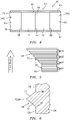
FIG. 5 is a side sectional illustration of a portion of the waveguide with the indent feature schematically depicting layer-by-layer additive manufacture. -
FIG. 6 is a side sectional illustration of a portion of the waveguide with the indent feature, which indent feature is configured with an eased exterior corner. -
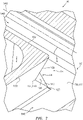
FIG. 7 is a perspective side sectional illustration of a portion of the waveguide with a notched corner. -
FIG. 8 is a cross-sectional illustration of a portion of the waveguide with the notched corner taken along line 8-8 inFIG. 7 . -
FIG. 9 is a side sectional illustration of a portion of the waveguide with the notched corner taken along line 9-9 inFIG. 8 . -
FIG. 10 is a side sectional illustration of a portion of the waveguide with the notched corner taken along line 10-10 inFIG. 8 . -
FIG. 11 is a cross-sectional illustration of a portion of the waveguide to one side of the notched corner. -
FIG. 12 is a cross-sectional illustration of a portion of the waveguide to another side of the notched corner. -
FIG. 13 is a side sectional illustration of a portion of the waveguide with the notched corner schematically depicting layer-by-layer additive manufacture. -
FIG. 14 is a cross-sectional illustration of a portion of the waveguide with the notched corner, which notched corner is configured with an eased interior corner. -
FIG. 15 is a perspective side sectional illustration of a portion of the waveguide with another notched corner. -
FIG. 16 is a perspective illustration of a waveguide with a hybrid T-junction. -
FIG. 17 is a perspective illustration of a waveguide with a cross-guide junction. -
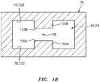
FIG. 18 is a cross-sectional illustration of a portion of the waveguide. -
FIG. 19 is a side schematic illustration of a gas turbine engine. -
FIG. 1 illustrates anoperation system 30 for equipment such as, but not limited to, a gas turbine engine. Thisequipment operation system 30 may be configured as or included in a control system, a sensor system and/or a communication system. Theequipment operation system 30 ofFIG. 1 includes a plurality ofsystem devices 32A-D (generally referred to as 32) and asignal communication apparatus 34 for facilitating communication between the system devices 32. - The system devices 32 may include a controller (e.g., an electronic control module (ECM)) and one or more sensors (e.g., probes). Examples of the sensors include, but are not limited to, a speed sensor, a power sensor, a temperature sensor (e.g., an exhaust gas temperature (EGT) sensor), a pressure sensor and a flow sensor. The system devices 32 may also or alternatively include one or more actuators. Examples of the actuators include, but are not limited to, an electronic valve for actuating a hydraulic or pneumatic device, an electronic pump for actuating a hydraulic or pneumatic device, and an electronic switch for actuating an electric motor. The system devices 32 may also or alternatively include one or more electronic ignition devices. Examples of the electronic ignition devices include, but are not limited to, electric spark ignition engine start devices and electronic pyro flare engine start devices. Of course, various other types of sensors, actuators and, more generally, system devices are known in the art, and the present disclosure is not limited to any particular ones thereof.
- The
signal communication apparatus 34 ofFIG. 1 includes amulti-path waveguide 36 and a plurality oftransceivers 38A-D (generally referred to as 38); e.g., input/output devices. Thewaveguide 36 is configured with at least one internal channel 40 (e.g., an internal waveguide passage) within thewaveguide 36. Thisinternal waveguide channel 40 is configured to provide a signal path for electric, magnetic and/or electromagnetic signal waves (e.g., radio frequency (RF) waves) between two ormore waveguide portals 42A-D (generally referred to as 42) of thewaveguide 36. The term waveguide portal may describe a signal input and/or output port for coupling at least one transceiver to a waveguide channel. One or more of the waveguide portals 42, for example, may each be configured as an aperture (e.g., a through hole) that extends through a portion (e.g., flanged coupling, wall, etc.) of thewaveguide 36 and that is fluidly coupled with theinternal waveguide channel 40. - The transceivers 38 are respectively configured in signal communication with (e.g., hardwired and/or wirelessly coupled to) at least one of the system devices 32. Each of the
transceivers FIG. 1 , for example, is configured in signal communication with a respective one of thesystem devices electrical conduit transceivers waveguide portals internal waveguide channel 40 to one or more of the other transceivers 38. Each of the transceivers 38 may also or alternatively thereby: (A) receive signal wave(s) transmitted through theinternal waveguide channel 40 from one or more of the other transceivers 38; and (B) convert the received signal wave(s) into a signal for transmission to the respective system device 32 through, for example, the electrical conduit 44. - The
waveguide 36 may be configured as a monolithic body. Herein, the term monolithic may describe an apparatus which is formed as a single unitary body. An entirety of thewaveguide 36 ofFIG. 1 , for example, may be additively manufactured, cast, machined and/or otherwise formed as a single unitary body. For example, thewaveguide 36 may be built up in a layer-by-layer fashion using an additive manufacturing process and an additive manufacturing device. Examples of the additive manufacturing process include a laser powder bed fusion (LPBF) process and an electron beam powder bed fusion process. Examples of the additive manufacturing device include a laser powder bed fusion (LPBF) device and an electron beam powder bed fusion device. Of course, various other additive manufacturing processes and devices are known in the art, and the present disclosure is not limited to any particular ones thereof. By contrast, a non-monolithic body may include discretely formed waveguide members, where the waveguide members are mechanically fastened and/or otherwise attached to one another post formation to provide a waveguide. - When using a formation process such as, but not limited to, additive manufacturing, one or more portions of a multi-path waveguide may be partially or completely unsupported during at least a portion of the formation process. The term unsupported may describe a portion of a waveguide that is unsupported (e.g., vertically / perpendicular relative to a build plane) during at least a portion of the formation process. For example, an unsupported portion of a waveguide may overlap (relative to the build plane) a void (e.g., a channel, a cavity, an opening, etc.), which void is located vertically beneath the unsupported portion. In another example, an unsupported portion of a waveguide may overlap (relative to the build plane) unsolidified material (e.g., powder), which unsolidified material is located beneath the unsupported portion. Such unsupported portions of a waveguide may be subject to formation defects such as, but not limited to: material sagging and/or other material deformation; non-spec porosity (e.g., porosity that is higher or lower than specified in a design for the waveguide); non-spec surface finish (e.g., surface finish that is rougher than specified in a design for the waveguide); internal flaws; etc.
- To mitigate formation defects, one or more (e.g., temporary or permanent) support structures may be integrated with the waveguide to support one or more of its otherwise unsupported portions. In general, these support structures are arranged outside of the waveguide so as to reduce or eliminate the need to remove material from within an internal channel of the waveguide post formation. Access to surfaces and/or features internal to a waveguide post formation may be difficult with conventional (e.g., line-of-sight) post-processing techniques (e.g., machining, surface finishing, etc.), particularly where the waveguide is formed as a monolithic body. Therefore, one or more
internal portion waveguide 36 ofFIG. 2 have supportless configurations. The term supportless may describe a structural configuration (e.g., shape, size, location, orientation, etc.) of a feature (e.g., an overhang feature) that provides self-support during formation. For example, each layer of material being solidified during additive manufacturing of the feature may be supported by a previously solidified layer without requiring an additional support structure as discussed below in further detail. Provision of the self-supportinginternal portions internal waveguide channel 40. - The self-supporting
internal portions waveguide 36 ofFIG. 2 are respectively configured atjunctions 50 and 52 (e.g., connections, nodes, etc.) betweenrespective segments 54A-E (generally referred to as 54) of theinternal waveguide channel 40. One or more of these channel segments (e.g., 54A, 54B, 54C and 54D) may be arranged at, extend towards a respective end / waveguide portal (e.g., 42A, 42B, 42C and 42D; see alsoFIG. 1 ) of thewaveguide 36. Thesechannel segments 54A-54D are therefore referred to below as end segments for ease of description. At least one of the channel segments (e.g., 54E) may be arranged intermediately between / extend between thejunctions channel segment 54E is therefore referred to below as an intermediate segment for ease of description. - The
first end segment 54A, thesecond end segment 54B and theintermediate segment 54E are interconnected at thefirst junction 50; e.g., a T-junction such as a magic tee junction (also known as a magic T junction). Thefirst end segment 54A extends, projects out / away from thefirst junction 50 towards thefirst transceiver 38A (seeFIG. 1 ); e.g., to thefirst waveguide portal 42A. Thesecond end segment 54B extends, projects out / away from thefirst junction 50 towards thesecond transceiver 38B (seeFIG. 1 ); e.g., to thesecond waveguide portal 42B. Theintermediate segment 54E extends, projects out / away from thefirst junction 50 towards (e.g., to) thesecond junction 52. With this arrangement, thesecond end segment 54B may form a base of the first junction 50 (e.g., a base of the T), and thefirst end segment 54A and theintermediate segment 54E may form arms of a top of the first junction 50 (e.g., a top of the T). At thefirst junction 50, acenterline 56A of thefirst end segment 54A may be parallel (e.g., coaxial) with acenterline 56E of theintermediate segment 54E. The firstend segment centerline 56A may be angularly offset from (e.g., perpendicular to) acenterline 56B of thesecond end segment 54B. The present disclosure, however, is not limited to the foregoing exemplary waveguide channel segment arrangement. For example, in other embodiments, the firstend segment centerline 56A may be non-parallel with (e.g., angularly offset from) the secondend segment centerline 56B. The firstend segment centerline 56A may also or alternatively be angularly offset from the secondend segment centerline 56B and/or theintermediate segment centerline 56E by a non-ninety degree angle; e.g., an acute or obtuse angle. - The
intermediate segment 54E, thethird end segment 54C and thefourth end segment 54D are interconnected at thesecond junction 52; e.g., a T-junction such as a magic tee junction. Theintermediate segment 54E extends, projects out / away from thesecond junction 52 towards (e.g., to) thefirst junction 50 in theinternal waveguide channel 40. Thethird end segment 54C extends, projects out / away from thesecond junction 52 towards thethird transceiver 32C (seeFIG. 1 ); e.g., to thethird waveguide portal 42C. Thefourth end segment 54D extends, projects out / away from thesecond junction 52 towards thefourth transceiver 32D (seeFIG. 1 ); e.g., to thefourth waveguide portal 42D (seeFIG. 1 ). With this arrangement, thethird end segment 54C may form a base of the second junction 52 (e.g., a base of the T), and thefourth end segment 54D and theintermediate segment 54E may form arms of a top of the second junction 52 (e.g., a top of the T). At thesecond junction 52, theintermediate segment centerline 56E may be parallel (e.g., coaxial) with acenterline 56D of thefourth end segment 54D. Theintermediate segment centerline 56E may be angularly offset from (e.g., perpendicular to) acenterline 56C of thethird end segment 54C. The present disclosure, however, is not limited to the foregoing exemplary waveguide channel segment arrangement. For example, in other embodiments, theintermediate segment centerline 56E may be non-parallel with (e.g., angularly offset from) the fourthend segment centerline 56D. Theintermediate segment centerline 56E may also or alternatively be angularly offset from the thirdend segment centerline 56C and/or the fourth segment centerline by a non-ninety degree angle; e.g., an acute or obtuse angle. - The first
internal portion 46 of thewaveguide 36 is arranged at thefirst junction 50. This firstinternal portion 46 is configured as or otherwise includes aprotrusion 58. Theprotrusion 58 ofFIG. 2 is configured as an indent feature. Theprotrusion 58, for example, is configured to provide impedance matching between thechannel segments - The
protrusion 58 is arranged opposite ajunction end 60 of thesecond end segment 54B at thefirst junction 50. Theprotrusion 58 ofFIG. 2 , for example, is located intermediately (e.g., centrally) between twoexterior corners waveguide 36 at thefirst junction 50. The verticallylower waveguide corner 62A is formed where thefirst end segment 54A meets thesecond end segment 54B. The verticallyupper waveguide corner 62B is formed where thesecond end segment 54B meets theintermediate segment 54E. - The
protrusion 58 is arranged along and is connected to asidewall 64 of thewaveguide 36 at thefirst junction 50. Thiswaveguide sidewall 64 includes (e.g., carries) anintermediate segment surface 66 and a firstend segment surface 68. Theintermediate segment surface 66 partially forms a side peripheral boundary of theintermediate segment 54E. The firstend segment surface 68 partially forms a side peripheral boundary of thefirst end segment 54A. This firstend segment surface 68 ofFIG. 2 is arranged parallel (e.g., coplanar) with theintermediate segment surface 66 at thefirst junction 50; however, the present disclosure is not limited to such an arrangement. - Referring to
FIG. 3 , theprotrusion 58 projects laterally (e.g., widthwise) out from thewaveguide sidewall 64 and itssurfaces distal end 70 of theprotrusion 58. Theprotrusion 58 includes (e.g., carries) afirst protrusion surface 72 and asecond protrusion surface 74. - Referring to
FIG. 4 , each of the protrusion surfaces 72 and 74 extends transversely (e.g., depthwise) between and to opposing (e.g., top and bottom) sides 76 and 78 of thewaveguide sidewall 64 at thefirst junction 50. Thus, theprotrusion 58 extends transversely across theinternal waveguide channel 40. - Referring to
FIG. 3 , thefirst protrusion surface 72 extends between and to the firstend segment surface 68 and thesecond protrusion surface 74. More particularly, thefirst protrusion surface 72 meets the firstend segment surface 68 at a firstinterior corner 80; e.g., a concave straight-line interface. Thefirst protrusion surface 72 is angularly offset from the firstend segment surface 68 by an includedangle 82; e.g., an obtuse angle. Thisangle 82 may be between one hundred and twenty two degrees (122°) and one hundred and forty degrees (140°); e.g., theangle 82 may be about (e.g., +/- 1°) one hundred and thirty five degrees (135°). Thefirst protrusion surface 72 meets thesecond protrusion surface 74 at anexterior corner 84; e.g., a convex straight-line interface / edge of theprotrusion 58 at itsdistal end 70. Thefirst protrusion surface 72 is angularly offset from thesecond protrusion surface 74 by an includedangle 86; e.g., a right angle, or an acute or obtuse angle. Thisangle 86 may be between sixty four degrees (64°) and one hundred and sixteen degrees (116°); e.g., theangle 86 may be about (e.g., +/- 1°) ninety degrees (90°). Theprotrusion 58 thereby tapers (e.g., in a longitudinal direction relative to thecenterlines protrusion 58 projects laterally to itsdistal end 70. Theprotrusion 58 ofFIG. 3 , more particularly, has a tapered (e.g., triangular) sectional geometry, for example, when viewed in a plane defined by two or more of the centerlines (e.g., 56A and 56B, 56B and 56E) at thefirst junction 50. - The
second protrusion surface 74 extends between and to theintermediate segment surface 66 and thefirst protrusion surface 72. More particularly, thesecond protrusion surface 74 meets theintermediate segment surface 66 at a secondinterior corner 88; e.g., a concave straight-line interface. Thesecond protrusion surface 74 is angularly offset from theintermediate segment surface 66 by an includedangle 90; e.g., an obtuse angle. Thisangle 90 may be equal to (or different than) theangle 82. Theangle 90, for example, may be between one hundred and twenty two degrees (122°) and one hundred and forty degrees (140°); e.g., theangle 90 may be about (e.g., +/- 1°) one hundred and thirty five degrees (135°). - With the foregoing configuration, the
protrusion 58 may be self-supported during formation. For example, referring toFIG. 5 , an overhanging portion of each layer ofmaterial 92 forming theprotrusion 58 may be at least partially supported by a previous layer ofmaterial 92 there beneath given theangle 82 between thesurfaces protrusion 58 ofFIG. 3 may therefore be formed without use of one or more additional support structures within thewaveguide 36. Furthermore, theprotrusion 58 is configured with symmetry by providing a similar / common angle between thesurfaces surfaces - In some embodiments, the
corner 84 between the protrusion surfaces 72 and 74 may be a sharp corner. In other embodiments, referring toFIG. 6 , thecorner 84 between the protrusion surfaces 72 and 74 may be an eased (e.g., rounded, chamfered, etc.) corner. One or more of thecorners - Referring to
FIG. 2 , the secondinternal portion 48 of thewaveguide 36 is arranged at thesecond junction 52. This secondinternal portion 48 is configured as or otherwise includes a vertically upper, exterior corner 94 (e.g., convex corner) of thewaveguide 36. Thisupper waveguide corner 94 is arranged opposite a vertically lower, exterior corner 96 (e.g., convex corner) of thewaveguide 36. Thislower waveguide corner 96 is formed where theintermediate segment 54E meets thethird end segment 54C. Theupper waveguide corner 94 is formed where thethird end segment 54C meets thefourth end segment 54D. - The
upper waveguide corner 94 ofFIGS. 7 and8 is configured as a notched corner. Thewaveguide 36 ofFIGS. 7 and8 , for example, is configured with atapered notch 98. Referring toFIGS. 7 ,9 and 10 , the taperednotch 98 projects laterally into thewaveguide 36 at thecorner 94 frominternal surfaces waveguide 36 to a distal end 104 of thenotch 98. The thirdend segment surface 100 partially forms a side peripheral boundary of thethird end segment 54C. The fourthend segment surface 102 partially forms a side peripheral boundary of thefourth end segment 54D. - The
tapered notch 98 is formed by a first notch surface 106 (seeFIG. 9 ) and a second notch surface 108 (seeFIG. 10 ). Each of these notch surfaces 106 and 108 extends laterally between and to thesurfaces end segment surface 100 at anexterior corner 110; e.g., a convex V-shaped interface / edge between thesurfaces exterior corner 110, referring toFIGS. 9 and 10 , eachnotch surface end segment surface 100 by anangle 112; e.g., an obtuse angle. Thisangle 112 may be between one hundred and twenty five degrees (125°) and one hundred and forty five degrees (145°); e.g., theangle 112 may be about (e.g., +/- 1°) one hundred and thirty five degrees (135°). Each of the notch surfaces 106 and 108 ofFIG. 7 meets the fourthend segment surface 102 at anexterior corner 114; e.g., a convex V-shaped interface / edge between thesurfaces exterior corner 114, referring toFIGS. 9 and 10 , eachnotch surface end segment surface 102 by anangle 116; e.g., an obtuse angle. Thisangle 116 may be between one hundred and twenty five degrees (125°) and one hundred and forty five degrees (145°); e.g., theangle 116 may be about (e.g., +/- 1°) one hundred and thirty five degrees (135°). - Referring to
FIGS. 7 and8 , thefirst notch surface 106 meets thesecond notch surface 108 at an interior corner 118; e.g., a concave straight-line interface between thesurfaces FIG. 8 , thefirst notch surface 106 is angularly offset from thesecond notch surface 108 by an includedangle 120; e.g., a right angle, or an acute or obtuse angle. Thisangle 120 may be between sixty four degrees (64°) and one hundred and sixteen degrees (116°); e.g., theangle 120 may be about (e.g., +/- 1°) ninety degrees (90°). - Referring to
FIGS. 8 and 9 , thefirst notch surface 106 extends diagonally (e.g., laterally and transversely) between and to the interior corner 118 and a base (e.g., bottom)surface 122 of thewaveguide 36 at thewaveguide side 78. As thefirst notch surface 106 extends from the interior corner 118 to thebase surface 122, thefirst notch surface 106 laterally tapers. Thefirst notch surface 106 therefore may have a tapered (e.g., triangular) geometry when viewed, for example, in a plane parallel with thefirst notch surface 106. Thefirst notch surface 106 ofFIG. 7 meets thebase surface 122 at, for example, a point / aninterior corner 123. Referring toFIG. 8 , thefirst notch surface 106 is angularly offset from thebase surface 122 at thecorner 123 by an includedangle 124; e.g., an obtuse angle. Thisangle 124 may be between one hundred and twenty two degrees (122°) and one hundred and forty degrees (140°); e.g., theangle 124 may be about (e.g., +/- 1°) one hundred and thirty five degrees (135°). - Referring to
FIGS. 8 and 10 , thesecond notch surface 108 extends diagonally (e.g., laterally and transversely) between and to the interior corner 118 and a base (e.g., top)surface 126 of thewaveguide 36 at thewaveguide side 76. Referring toFIG. 10 , as thesecond notch surface 108 extends from the interior corner 118 to thebase surface 126, thesecond notch surface 108 laterally tapers. Thesecond notch surface 108 therefore may have a tapered (e.g., triangular) geometry when viewed, for example, in a plane parallel with thesecond notch surface 108. Thesecond notch surface 108 ofFIG. 8 meets thebase surface 126 at a point / aninterior corner 128. Thesecond notch surface 108 is angularly offset from thebase surface 126 at thecorner 128 by an includedangle 130; e.g., an obtuse angle. Thisangle 130 may be between one hundred and twenty two degrees (122°) and one hundred and forty degrees (140°); e.g., theangle 130 may be about (e.g., +/- 1°) one hundred and thirty five degrees (135°). - Referring to
FIGS. 11 and 12 , each of the internal waveguide surfaces 100 and 102 extends transversely between and to the opposing base surfaces 122 and 126 along the respectiveexterior corners 110 and 114 (seeFIGS. 9 and 10 ). Each of the internal waveguide surfaces 100 and 102 meets thebase surface 122 at aninterior corner base surface 122 by an includedangle angle base surface 126 at aninterior corner base surface 126 by an includedangle angle - With the foregoing configuration, the second
internal portion 48 of thewaveguide 36 may be self-supported during formation. For example, referring toFIG. 13 , an overhanging portion of each layer ofmaterial 148 forming theupper waveguide corner 94 may be at least partially supported by a previous layer ofmaterial 148 there beneath given theangle surfaces upper waveguide corner 94 may therefore be formed without use of one or more additional support structures within thewaveguide 36. - Referring to
FIG. 8 , in some embodiments, the corner 118 between the notch surfaces 106 and 108 may be a sharp corner. In other embodiments, referring toFIG. 14 , the corner 118 between the notch surfaces 106 and 108 may be an eased (e.g., rounded, chamfered, etc.) corner. One or more of thecorners - Referring to
FIG. 2 , to provide symmetry at thesecond junction 52, thelower waveguide corner 96 may also be configured as a notched corner. For example, referring toFIGS. 2 and15 , thelower waveguide corner 96 may be configured as a mirror image of the upper waveguide corner 94 (seeFIG. 7 ). The present disclosure, however, is not limited to such a symmetrical configuration. - Each of the surfaces within the waveguide and bordering the internal waveguide channel 40 (e.g., the
surfaces waveguide 36. Each of these internal waveguide surfaces partially forms a peripheral boundary of theinternal waveguide channel 40 through thewaveguide 36. - While the
junctions internal waveguide channel 40, the configurations of the self-supportinginternal waveguide portions alternative junctions FIGS. 16 and 17 . - While the
waveguide channel segments 54A-D are described above as end segments, one or more of thesesegments waveguide channel segment 54E is described above as an intermediate segment, thissegment 54E may alternatively be configured as an end segment. The present disclosure therefore is not limited to the exemplary waveguide configuration ofFIG. 2 . - In some embodiments, referring to
FIG. 18 , at least a portion or an entirety of theinternal waveguide channel 40 may be configured with a lobed cross-sectional geometry when viewed, for example, in a plane perpendicular to thelongitudinal centerline 56 of a respective channel segment 54; e.g., plane ofFIG. 18 . Theinternal waveguide channel 40 ofFIG. 18 , for example, is configured with an H-shaped (or I-shaped) cross-sectional geometry. More particularly, the waveguide ofFIG. 18 includes one ormore lobes internal waveguide channel 40 between the different transceivers 38 (seeFIG. 1 ). Thefirst lobe 154A (e.g., rib) ofFIG. 18 , for example, is arranged at theside 78 along thebase surface 122. Thisfirst lobe 154A projects transversely partially into theinternal waveguide channel 40 to adistal end 156A. Thefirst lobe 154A extends longitudinally within theinternal waveguide channel 40 along the respectivelongitudinal centerline 56. Thesecond lobe 154B (e.g., rib) is arranged at theside 76 along thebase surface 126. Thissecond lobe 154B projects transversely partially into theinternal waveguide channel 40 to adistal end 156B. Thesecond lobe 154B extends longitudinally within theinternal waveguide channel 40 along the respectivelongitudinal centerline 56. Thesecond lobe 154B may be arranged opposite (e.g., diametrically opposed to) and/or aligned with thefirst lobe 154A. Thesecond lobe 154B may also or alternatively have the same cross-sectional geometry as thefirst lobe 154A at, for example, common locations along thelongitudinal centerline 56. At least a portion (or an entirety) of one or more exterior and/or interior corners of each lobe 154 may be eased (e.g., rounded, bullnosed, chamfered, etc.; seeFIG. 2 ). At least a portion (or an entirety) of one or more corners of each lobe 154 may also or alternatively be sharp (e.g., pointed, squared-off, etc.; seeFIGS. 2 and18 ). The present disclosure, however, is not limited to such exemplary waveguide channel cross-sectional geometries. For example, in other embodiments, thewaveguide 36 may include a single lobe (e.g., rib), more than two lobes 154 (e.g., ribs) or thewaveguide 36 may be configured without any lobes. - The
equipment operation system 30 ofFIG. 1 may be configured with various types and configurations of equipment.FIG. 19 illustrates one such type and configuration of the equipment - a one-spool, radial-flowturbojet turbine engine 158 configured for propelling an unmanned aerial vehicle (UAV), a drone or any other aircraft or self-propelled projectile. In the specific embodiment ofFIG. 19 , theturbine engine 158 includes anupstream inlet 160, a (e.g., radial)compressor section 162, thecombustor section 164, a (e.g., radial)turbine section 166 and adownstream exhaust 168 fluidly coupled in series. Acompressor rotor 170 in thecompressor section 162 is coupled with aturbine rotor 172 in theturbine section 166 by ashaft 174, which rotates about a centerline /rotational axis 176 of theturbine engine 158. - The
equipment operation system 30 may be included in various turbine engines other than the one described above. Theequipment operation system 30, for example, may be included in a geared turbine engine where a gear train connects one or more shafts to one or more rotors in a fan section, a compressor section and/or any other engine section. Alternatively, theequipment operation system 30 may be included in a turbine engine configured without a gear train. Theequipment operation system 30 may be included in a geared or non-geared turbine engine configured with a single spool (e.g., seeFIG. 19 ), with two spools, or with more than two spools. The turbine engine may be configured as a turbofan engine, a turbojet engine, a propfan engine, a pusher fan engine or any other type of turbine engine. The present disclosure therefore is not limited to any particular types or configurations of turbine engines. Furthermore, the present disclosure is not limited to turbine engine or aerospace applications. For example, theequipment operation system 30 may be configured with any piece of equipment which would benefit from communicating signals through thewaveguide 36. - While various embodiments of the present disclosure have been described, it will be apparent to those of ordinary skill in the art that many more embodiments and implementations are possible within the scope of the disclosure. For example, the present disclosure as described herein includes several aspects and embodiments that include particular features. Although these features may be described individually, it is within the scope of the present disclosure that some or all of these features may be combined with any one of the aspects and remain within the scope of the disclosure. Accordingly, the present disclosure is not to be restricted except in light of the attached claims and their equivalents.
Claims (15)
- An apparatus for signal communication, comprising:a waveguide (36) with an internal channel (40) that includes a plurality of channel segments (54) interconnected at a junction (50), the waveguide (36) including a first surface (68) and a second surface (72);the first surface (68) and the second surface (72) partially forming a peripheral boundary of the internal channel (40) at the junction (50), the first surface (68) meeting the second surface (72) at a first corner (80), and the first surface (68) angularly offset from the second surface (72) by an obtuse angle (82).
- The apparatus of claim 1, wherein the obtuse angle (82) is between one hundred and twenty two degrees and one hundred and forty eight degrees, and, optionally, the obtuse angle (82) is about one hundred and thirty five degrees.
- The apparatus of claim 1 or 2, wherein the first corner (80) is an interior corner.
- The apparatus of claim 1, 2 or 3, wherein:the waveguide (36) further includes a third surface (74) further forming the peripheral boundary of the internal channel (40) at the junction (50);the third surface (74) meets the second surface at a second corner (84); andthe second surface (72) is angularly offset from the third surface (74) by an angle (86) between sixty four degrees and one hundred and sixteen degrees, and, optionally, the angle (86) is about ninety degrees.
- The apparatus of claim 4, wherein the second corner (84) is an interior corner or exterior corner.
- The apparatus of claim 4 or 5, wherein:the waveguide (36) further includes a fourth surface (66) further forming the peripheral boundary of the internal channel (40) at the junction (50);the fourth surface (66) meets the third surface (74) at a third corner (88); andthe third surface (74) is angularly offset from the fourth surface (66) by an obtuse angle (90).
- The apparatus of claim 6, wherein the first surface (68) is parallel or coplanar with the fourth surface (66).
- The apparatus of any preceding claim, wherein the second surface (72) partially forms a corner at the junction (50) between a first of the plurality of channel segments (54A) and a second of the plurality of channel segments (54B).
- The apparatus of any preceding claim, wherein:the waveguide (36) includes an indent feature (58) located at the junction (50) opposite a first of the plurality of channel segments (54B); andthe indent feature (58) includes the second surface (72).
- The apparatus of any preceding claim, wherein the junction (50) is configured as a T-j unction.
- The apparatus of any preceding claim, wherein at least a portion of the internal channel (40) has a lobed cross-sectional geometry.
- The apparatus of any preceding claim, further comprising:a first transceiver (38A); anda second transceiver (38B) configured in signal communication with the first transceiver (38) through the internal channel (40).
- An apparatus for signal communication, comprising:a waveguide (36) including an internal channel (40) and a notched corner (94);the internal channel (40) including a first channel segment (54C) and a second channel segment (54D) meeting the first channel segment (54C) at a junction (52); andthe notched corner (94) located at the junction (52).
- The apparatus of claim 13, whereinthe notched corner (94) meets a first sidewall surface (100) partially forming the first channel segment (54C) at a first V-shaped interface (110); andthe notched corner (94) meets a second sidewall surface (102) partially forming the second channel segment (54D) at a second V-shaped interface (114).
- An apparatus for signal communication, comprising:a waveguide (36) including an internal channel (40), an indent feature (58) and a sidewall (64);the internal channel (40) including a first channel segment (54A), a second channel segment (54B) and a third channel segment (54E) that are interconnected at a junction (50); andthe indent feature (58) arranged at the junction (50) opposite the second channel segment (54B), the indent feature (58) projecting out from the sidewall (64) and having a tapered sectional geometry, wherein, optionally:the indent feature (58) includes a first surface (72) and a second surface (74) that meets the first surface (72) at a distal edge (70) of the indent feature (58); andthe first surface (72) is angularly offset from the second surface (74) by an angle (86) between sixty four degrees and one hundred and sixteen degrees.
Applications Claiming Priority (1)
| Application Number | Priority Date | Filing Date | Title |
|---|---|---|---|
| US17/119,316 US11936091B2 (en) | 2020-12-11 | 2020-12-11 | Waveguide apparatus including channel segments having surfaces that are angularly joined at a junction or a corner |
Publications (1)
| Publication Number | Publication Date |
|---|---|
| EP4012835A1 true EP4012835A1 (en) | 2022-06-15 |
Family
ID=78851134
Family Applications (1)
| Application Number | Title | Priority Date | Filing Date |
|---|---|---|---|
| EP21214151.9A Pending EP4012835A1 (en) | 2020-12-11 | 2021-12-13 | Waveguide with internal, self-supported feature(s) |
Country Status (2)
| Country | Link |
|---|---|
| US (1) | US11936091B2 (en) |
| EP (1) | EP4012835A1 (en) |
Families Citing this family (1)
| Publication number | Priority date | Publication date | Assignee | Title |
|---|---|---|---|---|
| US12512574B2 (en) * | 2021-12-30 | 2025-12-30 | Raytheon Company | Waveguide components of waveguides formed with additive manufacturing |
Citations (3)
| Publication number | Priority date | Publication date | Assignee | Title |
|---|---|---|---|---|
| US4642586A (en) * | 1984-04-20 | 1987-02-10 | Adams-Russell | Low SWR high power multiple waveguide junction |
| US20100102899A1 (en) * | 2008-10-27 | 2010-04-29 | Starling Advanced Communications Ltd. | Waveguide antenna front end |
| US20180183129A1 (en) * | 2016-12-22 | 2018-06-28 | Raytheon Company | Magic-y splitter |
Family Cites Families (13)
| Publication number | Priority date | Publication date | Assignee | Title |
|---|---|---|---|---|
| GB637109A (en) * | 1947-04-17 | 1950-05-10 | Charles Walter Miller | Improvements relating to electromagnetic waveguides |
| US2810111A (en) * | 1950-11-25 | 1957-10-15 | Sperry Rand Corp | Wave guide corner |
| US3150333A (en) * | 1960-02-01 | 1964-09-22 | Airtron Division Of Litton Pre | Coupling orthogonal polarizations in a common square waveguide with modes in individual waveguides |
| DE1790171C2 (en) * | 1968-09-21 | 1974-08-01 | Telefunken Patentverwertungsgesellschaft Mbh, 7900 Ulm | Broadband waveguide |
| JP3879548B2 (en) * | 2002-03-20 | 2007-02-14 | 三菱電機株式会社 | Waveguide type demultiplexer |
| US20130265733A1 (en) * | 2012-04-04 | 2013-10-10 | Texas Instruments Incorporated | Interchip communication using an embedded dielectric waveguide |
| GB2528880A (en) | 2014-08-01 | 2016-02-10 | Bae Systems Plc | Foreign object debris detection system and method |
| JP6526509B2 (en) * | 2015-07-23 | 2019-06-05 | 株式会社東芝 | Waveguide bend and radio equipment |
| US10096880B2 (en) | 2015-09-01 | 2018-10-09 | Duke University | Waveguide comprising first and second components attachable together using an extruding lip and an intruding groove |
| EP3353850A4 (en) | 2015-09-25 | 2019-05-15 | Bae Systems Australia Limited | An rf structure and a method of forming an rf structure |
| US10751988B1 (en) | 2015-12-07 | 2020-08-25 | Made In Space, Inc. | Additive manufactured waveguides |
| US10307138B2 (en) | 2017-04-06 | 2019-06-04 | United Technologies Corporation | Wave guide with electric power conduit |
| US10573949B2 (en) | 2017-07-31 | 2020-02-25 | Space Systems/Loral, Llc | Additive manufactured RF module |
-
2020
- 2020-12-11 US US17/119,316 patent/US11936091B2/en active Active
-
2021
- 2021-12-13 EP EP21214151.9A patent/EP4012835A1/en active Pending
Patent Citations (3)
| Publication number | Priority date | Publication date | Assignee | Title |
|---|---|---|---|---|
| US4642586A (en) * | 1984-04-20 | 1987-02-10 | Adams-Russell | Low SWR high power multiple waveguide junction |
| US20100102899A1 (en) * | 2008-10-27 | 2010-04-29 | Starling Advanced Communications Ltd. | Waveguide antenna front end |
| US20180183129A1 (en) * | 2016-12-22 | 2018-06-28 | Raytheon Company | Magic-y splitter |
Non-Patent Citations (3)
| Title |
|---|
| ALESSANDRI F ET AL: "Rigorous analysis of compensated E-plane junctions in rectangular waveguide", MICROWAVE SYMPOSIUM DIGEST, 1995., IEEE MTT-S INTERNATIONAL ORLANDO, FL, USA 16-20 MAY 1995, NEW YORK, NY, USA,IEEE, US, 16 May 1995 (1995-05-16), pages 987 - 990vol.2, XP032444911, ISBN: 978-0-7803-2581-4, DOI: 10.1109/MWSYM.1995.406138 * |
| GENC A ET AL: "Fabrication of three-dimensional printed rectangular waveguide T-junction with in-phase and equal power division", vol. 60, no. 8, 15 June 2018 (2018-06-15), US, pages 2043 - 2048, XP055900135, ISSN: 0895-2477, Retrieved from the Internet <URL:https://api.wiley.com/onlinelibrary/tdm/v1/articles/10.1002%2Fmop.31294> DOI: 10.1002/mop.31294 * |
| YAMAMOTO T ED - GLUBOKOV A ET AL: "Numerical analysis of H-plane waveguide junctions by using densely arrayed electric line currents", ANTENNAS AND PROPAGATION SOCIETY INTERNATIONAL SYMPOSIUM, 2008. AP-S 2008. IEEE, IEEE, PISCATAWAY, NJ, USA, 5 July 2008 (2008-07-05), pages 1 - 4, XP031824842, ISBN: 978-1-4244-2041-4 * |
Also Published As
| Publication number | Publication date |
|---|---|
| US11936091B2 (en) | 2024-03-19 |
| US20220190460A1 (en) | 2022-06-16 |
Similar Documents
| Publication | Publication Date | Title |
|---|---|---|
| EP4012835A1 (en) | Waveguide with internal, self-supported feature(s) | |
| EP3401513B1 (en) | Wave guide with electric power conduit | |
| Shang et al. | $ W $-band waveguide filters fabricated by laser micromachining and 3-D printing | |
| US20150121889A1 (en) | Aircraft nozzle | |
| US20220293077A1 (en) | Method for manufacturing an acoustic absorption structure, and acoustic absorption structure obtained in this way | |
| GB2563222A (en) | Core positioning in wax pattern die, and associated method and apparatus | |
| EP3009606A1 (en) | Carriers for turbine components | |
| US20180369969A1 (en) | Method of positioning a hollow workpiece | |
| US9404369B2 (en) | Airfoil having minimum distance ribs | |
| WO2013064242A2 (en) | Method for inspecting a gas turbine | |
| CN110806210B (en) | Unmanned aerial vehicle calibration direction-finding equipment route planning method and flight control method thereof | |
| US11441451B2 (en) | Turbine engine component with integrated waveguide | |
| EP4650825A2 (en) | Multi-mode microwave waveguide blade sensing system | |
| RU2406849C1 (en) | Method of automatic control of gas turbine engine thrust | |
| EP4606995A2 (en) | Method for forming cooling apertures in a coated turbine engine component | |
| US20040233014A1 (en) | Directional coupler in coplanar waveguide technology | |
| US11337298B2 (en) | Radio frequency electron accelerator for local frequency modulation and frequency modulation method thereof | |
| US11078820B2 (en) | Method for producing a honeycomb structure | |
| EP3885558A1 (en) | Exhaust baffle component for an air turbine assembly | |
| US12535034B1 (en) | Joint between aircraft engine components with spring beams | |
| US20250232665A1 (en) | Multi-role rf communication system | |
| US20220235672A1 (en) | Turbomachine output bearing support | |
| US20160237948A1 (en) | Divergent flap | |
| US20250042011A1 (en) | Rigidizable insertion tool | |
| EP4008495B1 (en) | Insertion tool |
Legal Events
| Date | Code | Title | Description |
|---|---|---|---|
| PUAI | Public reference made under article 153(3) epc to a published international application that has entered the european phase |
Free format text: ORIGINAL CODE: 0009012 |
|
| STAA | Information on the status of an ep patent application or granted ep patent |
Free format text: STATUS: THE APPLICATION HAS BEEN PUBLISHED |
|
| AK | Designated contracting states |
Kind code of ref document: A1 Designated state(s): AL AT BE BG CH CY CZ DE DK EE ES FI FR GB GR HR HU IE IS IT LI LT LU LV MC MK MT NL NO PL PT RO RS SE SI SK SM TR |
|
| STAA | Information on the status of an ep patent application or granted ep patent |
Free format text: STATUS: REQUEST FOR EXAMINATION WAS MADE |
|
| 17P | Request for examination filed |
Effective date: 20221215 |
|
| RBV | Designated contracting states (corrected) |
Designated state(s): AL AT BE BG CH CY CZ DE DK EE ES FI FR GB GR HR HU IE IS IT LI LT LU LV MC MK MT NL NO PL PT RO RS SE SI SK SM TR |
|
| RAP3 | Party data changed (applicant data changed or rights of an application transferred) |
Owner name: RTX CORPORATION |
|
| GRAP | Despatch of communication of intention to grant a patent |
Free format text: ORIGINAL CODE: EPIDOSNIGR1 |
|
| STAA | Information on the status of an ep patent application or granted ep patent |
Free format text: STATUS: GRANT OF PATENT IS INTENDED |
|
| INTG | Intention to grant announced |
Effective date: 20260305 |