EP4012603A1 - Method for classifying a tracked object - Google Patents
Method for classifying a tracked object Download PDFInfo
- Publication number
- EP4012603A1 EP4012603A1 EP20212928.4A EP20212928A EP4012603A1 EP 4012603 A1 EP4012603 A1 EP 4012603A1 EP 20212928 A EP20212928 A EP 20212928A EP 4012603 A1 EP4012603 A1 EP 4012603A1
- Authority
- EP
- European Patent Office
- Prior art keywords
- neural network
- point
- features
- layers
- tracker
- Prior art date
- Legal status (The legal status is an assumption and is not a legal conclusion. Google has not performed a legal analysis and makes no representation as to the accuracy of the status listed.)
- Granted
Links
Images

Classifications
-
- G—PHYSICS
- G01—MEASURING; TESTING
- G01S—RADIO DIRECTION-FINDING; RADIO NAVIGATION; DETERMINING DISTANCE OR VELOCITY BY USE OF RADIO WAVES; LOCATING OR PRESENCE-DETECTING BY USE OF THE REFLECTION OR RERADIATION OF RADIO WAVES; ANALOGOUS ARRANGEMENTS USING OTHER WAVES
- G01S13/00—Systems using the reflection or reradiation of radio waves, e.g. radar systems; Analogous systems using reflection or reradiation of waves whose nature or wavelength is irrelevant or unspecified
- G01S13/66—Radar-tracking systems; Analogous systems
- G01S13/72—Radar-tracking systems; Analogous systems for two-dimensional [2D] tracking, e.g. combination of angle and range tracking, track-while-scan radar
- G01S13/723—Radar-tracking systems; Analogous systems for two-dimensional [2D] tracking, e.g. combination of angle and range tracking, track-while-scan radar by using numerical data
- G01S13/726—Multiple target tracking
-
- G—PHYSICS
- G06—COMPUTING OR CALCULATING; COUNTING
- G06F—ELECTRIC DIGITAL DATA PROCESSING
- G06F18/00—Pattern recognition
- G06F18/20—Analysing
- G06F18/25—Fusion techniques
- G06F18/254—Fusion techniques of classification results, e.g. of results related to same input data
-
- G—PHYSICS
- G06—COMPUTING OR CALCULATING; COUNTING
- G06F—ELECTRIC DIGITAL DATA PROCESSING
- G06F18/00—Pattern recognition
- G06F18/20—Analysing
- G06F18/25—Fusion techniques
- G06F18/253—Fusion techniques of extracted features
-
- G—PHYSICS
- G01—MEASURING; TESTING
- G01S—RADIO DIRECTION-FINDING; RADIO NAVIGATION; DETERMINING DISTANCE OR VELOCITY BY USE OF RADIO WAVES; LOCATING OR PRESENCE-DETECTING BY USE OF THE REFLECTION OR RERADIATION OF RADIO WAVES; ANALOGOUS ARRANGEMENTS USING OTHER WAVES
- G01S13/00—Systems using the reflection or reradiation of radio waves, e.g. radar systems; Analogous systems using reflection or reradiation of waves whose nature or wavelength is irrelevant or unspecified
- G01S13/02—Systems using reflection of radio waves, e.g. primary radar systems; Analogous systems
- G01S13/06—Systems determining position data of a target
- G01S13/08—Systems for measuring distance only
-
- G—PHYSICS
- G01—MEASURING; TESTING
- G01S—RADIO DIRECTION-FINDING; RADIO NAVIGATION; DETERMINING DISTANCE OR VELOCITY BY USE OF RADIO WAVES; LOCATING OR PRESENCE-DETECTING BY USE OF THE REFLECTION OR RERADIATION OF RADIO WAVES; ANALOGOUS ARRANGEMENTS USING OTHER WAVES
- G01S13/00—Systems using the reflection or reradiation of radio waves, e.g. radar systems; Analogous systems using reflection or reradiation of waves whose nature or wavelength is irrelevant or unspecified
- G01S13/02—Systems using reflection of radio waves, e.g. primary radar systems; Analogous systems
- G01S13/50—Systems of measurement based on relative movement of target
- G01S13/58—Velocity or trajectory determination systems; Sense-of-movement determination systems
-
- G—PHYSICS
- G01—MEASURING; TESTING
- G01S—RADIO DIRECTION-FINDING; RADIO NAVIGATION; DETERMINING DISTANCE OR VELOCITY BY USE OF RADIO WAVES; LOCATING OR PRESENCE-DETECTING BY USE OF THE REFLECTION OR RERADIATION OF RADIO WAVES; ANALOGOUS ARRANGEMENTS USING OTHER WAVES
- G01S13/00—Systems using the reflection or reradiation of radio waves, e.g. radar systems; Analogous systems using reflection or reradiation of waves whose nature or wavelength is irrelevant or unspecified
- G01S13/88—Radar or analogous systems specially adapted for specific applications
-
- G—PHYSICS
- G01—MEASURING; TESTING
- G01S—RADIO DIRECTION-FINDING; RADIO NAVIGATION; DETERMINING DISTANCE OR VELOCITY BY USE OF RADIO WAVES; LOCATING OR PRESENCE-DETECTING BY USE OF THE REFLECTION OR RERADIATION OF RADIO WAVES; ANALOGOUS ARRANGEMENTS USING OTHER WAVES
- G01S13/00—Systems using the reflection or reradiation of radio waves, e.g. radar systems; Analogous systems using reflection or reradiation of waves whose nature or wavelength is irrelevant or unspecified
- G01S13/88—Radar or analogous systems specially adapted for specific applications
- G01S13/93—Radar or analogous systems specially adapted for specific applications for anti-collision purposes
- G01S13/931—Radar or analogous systems specially adapted for specific applications for anti-collision purposes of land vehicles
-
- G—PHYSICS
- G01—MEASURING; TESTING
- G01S—RADIO DIRECTION-FINDING; RADIO NAVIGATION; DETERMINING DISTANCE OR VELOCITY BY USE OF RADIO WAVES; LOCATING OR PRESENCE-DETECTING BY USE OF THE REFLECTION OR RERADIATION OF RADIO WAVES; ANALOGOUS ARRANGEMENTS USING OTHER WAVES
- G01S7/00—Details of systems according to groups G01S13/00, G01S15/00, G01S17/00
- G01S7/02—Details of systems according to groups G01S13/00, G01S15/00, G01S17/00 of systems according to group G01S13/00
- G01S7/41—Details of systems according to groups G01S13/00, G01S15/00, G01S17/00 of systems according to group G01S13/00 using analysis of echo signal for target characterisation; Target signature; Target cross-section
- G01S7/417—Details of systems according to groups G01S13/00, G01S15/00, G01S17/00 of systems according to group G01S13/00 using analysis of echo signal for target characterisation; Target signature; Target cross-section involving the use of neural networks
-
- G—PHYSICS
- G06—COMPUTING OR CALCULATING; COUNTING
- G06F—ELECTRIC DIGITAL DATA PROCESSING
- G06F18/00—Pattern recognition
- G06F18/20—Analysing
- G06F18/24—Classification techniques
- G06F18/241—Classification techniques relating to the classification model, e.g. parametric or non-parametric approaches
- G06F18/2413—Classification techniques relating to the classification model, e.g. parametric or non-parametric approaches based on distances to training or reference patterns
- G06F18/24133—Distances to prototypes
- G06F18/24137—Distances to cluster centroïds
- G06F18/2414—Smoothing the distance, e.g. radial basis function networks [RBFN]
-
- G—PHYSICS
- G06—COMPUTING OR CALCULATING; COUNTING
- G06N—COMPUTING ARRANGEMENTS BASED ON SPECIFIC COMPUTATIONAL MODELS
- G06N3/00—Computing arrangements based on biological models
- G06N3/02—Neural networks
- G06N3/04—Architecture, e.g. interconnection topology
-
- G—PHYSICS
- G06—COMPUTING OR CALCULATING; COUNTING
- G06N—COMPUTING ARRANGEMENTS BASED ON SPECIFIC COMPUTATIONAL MODELS
- G06N3/00—Computing arrangements based on biological models
- G06N3/02—Neural networks
- G06N3/04—Architecture, e.g. interconnection topology
- G06N3/044—Recurrent networks, e.g. Hopfield networks
-
- G—PHYSICS
- G06—COMPUTING OR CALCULATING; COUNTING
- G06N—COMPUTING ARRANGEMENTS BASED ON SPECIFIC COMPUTATIONAL MODELS
- G06N3/00—Computing arrangements based on biological models
- G06N3/02—Neural networks
- G06N3/04—Architecture, e.g. interconnection topology
- G06N3/044—Recurrent networks, e.g. Hopfield networks
- G06N3/0442—Recurrent networks, e.g. Hopfield networks characterised by memory or gating, e.g. long short-term memory [LSTM] or gated recurrent units [GRU]
-
- G—PHYSICS
- G06—COMPUTING OR CALCULATING; COUNTING
- G06N—COMPUTING ARRANGEMENTS BASED ON SPECIFIC COMPUTATIONAL MODELS
- G06N3/00—Computing arrangements based on biological models
- G06N3/02—Neural networks
- G06N3/04—Architecture, e.g. interconnection topology
- G06N3/045—Combinations of networks
-
- G—PHYSICS
- G06—COMPUTING OR CALCULATING; COUNTING
- G06N—COMPUTING ARRANGEMENTS BASED ON SPECIFIC COMPUTATIONAL MODELS
- G06N3/00—Computing arrangements based on biological models
- G06N3/02—Neural networks
- G06N3/08—Learning methods
Definitions
- the present disclosure relates to a method for classifying a tracked object in an environment of a vehicle which includes a plurality of radar sensors and a processing device configured to establish a neural network.
- Modern vehicles are often provided with one or more radar sensors in order to be able to detect and to track an object in the environment of the vehicle.
- Conventional tracker systems which rely on data provided by the radar sensors of the vehicle can usually provide spatial information of objects only, e.g. information regarding location and velocity of the detected objects.
- ADAS Advanced Driver Assistance System
- additional semantic information regarding detected objects is important, i.e. information regarding the type of the detected object. For example, a pedestrian may have a higher priority for performing auto-breaking than some small patches of debris on the road. In such a case, detecting and tracking an object is not sufficient for making a proper decision regarding the navigation of the vehicle.
- a simple classification may be applied to the perception of objects.
- a Bayesian classifier may be used which turned out, however, not to have a reliable performance in some relevant driving situations.
- neural networks have been proposed for providing a semantic segmentation based on radar point clouds. Although a good performance has been achieved on test data, a deep neural network being used for providing semantic segmentation on radar point clouds requires a complex computation and a high computational effort exceeding the limitations of computer systems which are available in a vehicle. Therefore, providers of passenger cars have mostly refrained so far from implementing such neural networks which are applied to radar detections for semantic segmentation.
- the present disclosure provides a computer implemented method, a computer system and a non-transitory computer readable medium according to the independent claims. Embodiments are given in the subclaims, the description and the drawings.
- the present disclosure is directed at a computer implemented method for classifying a tracked object in an environment of a vehicle which includes a plurality of radar sensors and a processing device configured to establish a neural network.
- a computer implemented method for classifying a tracked object in an environment of a vehicle which includes a plurality of radar sensors and a processing device configured to establish a neural network.
- local radar detections are captured from an object in the environment of the vehicle via the radar sensors.
- point features and tracker features are determined.
- the point features are encoded via point encoding layers of the neural network
- the tracker features are encoded via track encoding layers of the neural network.
- a temporal fusion of the encoded point features and the encoded tracker features is performed via temporal fusion layers of the neural network.
- the tracked object is classified based on the fused encoded point and tracker features via classifying layers of the neural network.
- the method according to the disclosure may easily be implemented in existing systems and merged with existing tracking procedures. Therefore, hardware components may be used for executing the method which are already available on the vehicle, and the method according to the disclosure may therefore be implemented at low cost.
- the neural network is running individually on each track of the detected objects. Therefore, only local radar detections are considered, and no global information of the environment is required for the method. This again reduces the effort and the cost for performing the method according to the disclosure.
- the neural network may include fully connected layers, wherein the point encoding layers, the track encoding layers, the temporal fusion layers and the classifying layers may each form a separate group of layers of the neural network. For each group of these layers, a predefined minimum number and a predefined maximum number of layers may be set, for example two to four layers. If there are too many layers, the neural network will not be able to run in real time. On the other hand, if the number of layers is too low, the network may not be able to perform a suitable classification.
- the method according to the disclosure is suitable for an application on standard computational systems of passenger cars.
- the point features may comprise a radar cross section of each radar detection, a distance of each radar detection with respect to a track center, i.e. with respect to a centroid of the track, and a compensated Doppler value, i.e. a relative velocity of a respective radar detection with respect to the vehicle, wherein the velocity may be originally determined relative to a respective radar sensor and thereafter compensated for the motion of the vehicle.
- the point features may be determined for a time sequence of a certain number of subsequent radar detections, e.g. for ten subsequent detections.
- the tracker features may include a variance of velocity for each track, a length of each track, a velocity for each track in a vehicle coordinate system, a tangential acceleration for each track, a variance of a heading direction for each track, i.e. of the direction of the velocity vector, an absolute value of curvature of each track, and an absolute difference of a pointing direction between two adjacent scans of the track in a world coordinate system.
- classes for objects may be predefined, wherein the classes may be e.g. labeled as "car” (i.e. a small vehicle), “truck/bus” (i.e. a large vehicle), “pedestrian”, “motorcycle”, “bicycle”, and “background” (which refers to unknown objects which may not be cared about).
- the classes are not restricted to these examples, and the predefinition of the classes may be performed flexibly in order to adapt the method to the requirements within the respective vehicle, i.e. within a respective Advanced Driver Assistance System (ADAS).
- ADAS Advanced Driver Assistance System
- the method is able to provide semantic information regarding the detected objects in addition to the spatial information provided by standard tracking methods. Due to the additional semantic information which may be provided to the Advanced Driver Assistance System of the vehicle, the navigation of the vehicle may be generally improved, especially regarding navigation decisions which are to be taken.
- the method may comprise one or more of the following features:
- the point encoding layers of the neural network may encode each point feature separately and thereafter, a feature pooling may be performed by feature pooling layers of the neural network.
- the feature pooling may include a maximum pooling or an average pooling.
- the temporal fusion layers of the neural network may form a recurrent neural network.
- the recurrent neural network may be configured as a gated recurrent unit or as a long-short term memory.
- Each layer of the neural network may include a predefined maximum number of neurons.
- a predetermined number of the local radar detections may be sampled before the point features are determined based on local radar detections.
- Performing the temporal fusion may include performing a hidden state reset.
- the point encoding layers of the neural network may encode each point feature separately and thereafter, a feature pooling may be performed by feature pooling layers of the neural network.
- the feature pooling may include a maximum pooling or alternatively an average pooling. Due to the feature pooling, features from different points related to radar detections or from different point features may merged which may support the classification task of the neural network.
- the temporal fusion layers of the neural network may form a recurrent neural network (RNN), which may be configured either as gated recurrent unit (GRU) or alternatively as a long-short term memory (LSTM). Since a recurrent neural network (RNN) has connections between paths and connections through time, i.e. feedback, as an intrinsic property, the temporal fusion or fusion of the encoded point and tracker features "over time" may be performed automatically when using a recurrent neural network. The internal feedback of the recurrent neural network may further support the classification task of the method.
- the gated recurrent unit (GRU) may generally need less parameters than the long-short term memory (LSTM) and may therefore require less memory and computational effort.
- the long-short term memory (LSTM) may increase the precision and reliability of the neural network and the method.
- Each layer of the neural network may include a predefined maximum number of neurons.
- the maximum number of neurons per layer may be restricted to 256. Due to this restriction, the real-time capability of the neural network and the entire method may be ensured.
- a predetermined number of local radar detections may be sampled before the point features are determined based on local radar detections.
- the predetermined number may be for example ten detections. Due to this minimum number being required for determining the point features, the reliability of the determined point features may be enhanced.
- Performing the temporal fusion may include performing a hidden state reset within the neural network.
- the reset may be performed periodically, e.g. each 20 to 80 radar scans or each one to four seconds. Due to this reset, noise kept in hidden states of the temporal fusion layers may be reduced, which again may enhance the quality of the classification task. However, no reset may be performed as an alternative when performing the temporal fusion of the encoded features.
- the present disclosure is directed at a system for classifying a tracked object in the environment of a vehicle.
- the system includes a plurality of radar sensors configured to capture local radar detections from an object in the environment of the vehicle, a point feature module configured to determine point features based on the local radar detections, a tracker feature module configured to determine tracker features based on the local radar detections, and a processing device configured to establish a neural network.
- the processing device comprises a point encoding module including point encoding layers of the neural network which encode the point features, a track encoding module including track encoding layers of the neural network which encode the tracker features, a temporal fusion module including temporal fusion layers of the neural network which perform a temporal fusion of the encoded point features and the encoded tracker features, and a classification module including classifying layers of the neural network which classify the tracked object based on the fused encoded point and tracker features.
- module may refer to, be part of, or include an Application Specific Integrated Circuit (ASIC); an electronic circuit; a combinational logic circuit; a field programmable gate array (FPGA); a processor (shared, dedicated, or group) that executes code; other suitable components that provide the described functionality; or a combination of some or all of the above, such as in a system-on-chip.
- ASIC Application Specific Integrated Circuit
- FPGA field programmable gate array
- processor shared, dedicated, or group
- the term module may include memory (shared, dedicated, or group) that stores code executed by the processor.
- the system according to the disclosure includes the radar sensors, the point feature module, the tracker feature module and the processing device including four further modules which are installed in the vehicle and which are configured to perform the steps as described above for the corresponding method.
- the point encoding module may include additional layers of the neural network which perform a feature pooling.
- the feature pooling may facilitate the classification of tracked objects.
- the point feature module may include a flexible list of point features
- the tracker feature module may include a flexible list of tracker features.
- the system may be adapted to existing and future tracking devices due to the flexible lists of features.
- the present disclosure is directed at a computer system, said computer system being configured to carry out several or all steps of the computer implemented method described herein.
- the computer system may comprise a processing unit, at least one memory unit and at least one non-transitory data storage.
- the non-transitory data storage and/or the memory unit may comprise a computer program for instructing the computer to perform several or all steps or aspects of the computer implemented method described herein.
- the present disclosure is directed at a non-transitory computer readable medium comprising instructions for carrying out several or all steps or aspects of the computer implemented method described herein.
- the computer readable medium may be configured as: an optical medium, such as a compact disc (CD) or a digital versatile disk (DVD); a magnetic medium, such as a hard disk drive (HDD); a solid state drive (SSD); a read only memory (ROM); a flash memory; or the like.
- the computer readable medium may be configured as a data storage that is accessible via a data connection, such as an inter-net connection.
- the computer readable medium may, for example, be an online data repository or a cloud storage.
- the present disclosure is also directed at a computer program for instructing a computer to perform several or all steps or aspects of the computer implemented method described herein.
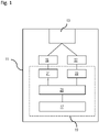
- Fig. 1 schematically depicts a vehicle 11 including a plurality of radar sensors 13, a point feature module 15, a tracker feature module 17 and a processing device 19.
- the radar sensors 13, the point feature module 15 and the tracker feature module 17 may already be incorporated in a known modern vehicle 11 which is equipped with a system configured to track objects in the environment of the vehicle 11.
- the processing device 19 is configured to perform a method according to the disclosure as described below. Therefore, the processing device 19 includes a point encoding module 21, a track encoding module 23, a temporal fusion module 25 and a classification module 27. By these modules, the processing device 19 is not only able to track objects in the environment of the vehicle 11 spatially, but it is also able to provide semantic information regarding the type of the tracked objects.
- the radar sensors 13 include four short range radars. Two of these radars are installed in the front of the vehicle on the left side and on the right side, whereas further two radars are installed in the rear of the vehicle on the left side and on the right side, respectively.
- the use of the system and the method according to the disclosure is not restricted to a radar system including four short range radars.
- a system including two radars which are installed on the left side and on the right side in the front of the vehicle only or a system including six short range radars (two additional radars in the center of the vehicle on the left and on the right sides, respectively) could be used.
- the radar sensors 13 are generally part of a centralized tracking system which can be found in many modern vehicles.
- Such a centralized tracking system usually includes the tracker feature module 17 which provides tracker features 18 (see Fig. 2 ) as output.
- Ft tracker features are provided by the tracker feature module 17, wherein Ft is 7 for the present example.
- the tracker features 18 include a variance of a velocity of a track (i.e. of an object which is tracked by the radar sensors 13), a length of the track, a velocity of the track in a vehicle coordinate system (VCS), a tangential acceleration of the track, a variance of a heading direction of the track, an absolute value of a curvature of the track, and an absolute difference of a pointing direction between two adjacent scans of the track in a world coordinate system (WCS).
- the heading direction refers to the direction of a velocity vector of the detected or tracked object.
- the pointing direction refers to an orientation of a body frame of the track
- the absolute difference of the pointing direction refers to such from two adjacent radar scans.
- the centralized tracking system of the vehicle 11 includes the point feature module 15 which outputs point features 16 (see Fig. 2 ).
- point features 16 there are Fp point features 16, wherein for present embodiment, Fp is 3 and the point features 16 include a radar cross section (RCS) of a current radar detection of the radar sensors 13, a distance of the detection with respect to a track center (i.e. to the centroid of the track), and a compensated Doppler value, i.e. the relative velocity of the respective detection with respect to the vehicle 11.
- the Doppler values are first determined relative to the respective radar sensor and afterwards compensated for the ego-motion of the vehicle 11.
- each of the three point features 16 is determined for a sequence of ten subsequent detections in order to provide a set of point features 16 as an input for the point feature encoding module 21, i.e. as an output of the point feature module 15. That is, the radar detections of the radar sensors 13 are "upsampled" until the number of measured detections reaches ten.
- Fig. 2 depicts the modules of the processing device 19 and the method steps performed by these modules in more detail.
- the point encoding module 21 and the track encoding module 23 receive the point features 16 and the tracker features 18, respectively, as an input from the point feature module 15 and from the tracker feature module 17, respectively.
- Fp x nP point features 16 i.e. 3 x 10 for the present embodiment
- Ft tracker features 18 i.e. seven for the present embodiment
- the point encoding module 21 includes two fully connected layers 29 of a neural network which are used for point encoding, i.e. applied to each of the point features 16.
- each point feature is encoded separately, and therefore the point encoding module 21 includes nP sets of respective pairs of fully connected layers 29 for point encoding, wherein nP is the number of detections to be considered and equal to ten for the present embodiment.
- neurons of the fully connected layers include a plurality of weights W and a bias b, as is known in the field of neural networks. That is, the output of the neurons of a layer is obtained by applying a non-linear function on W x + b, wherein x is a respective input vector of the layer which is multiplied by the matrix W of the weights.
- a total number of pC2 x nP encoded point features are output by all fully connected layers 29 for point encoding, i.e. a total number of 320 for the present embodiment.
- These encoded point features are used as an input for further fully connected layers 31 for feature pooling.
- a maximum pooling is performed by these layers 31 in order to merge features from different points or point features 16.
- the mechanism of maximum pooling is known in the art.
- average pooling could be used.
- the outputs of the point encoding module 21 and of the track encoding module 23, i.e. the encoded point and tracker features, are provided as an input for the temporal fusion module 25.
- the temporal fusion module 25 first performs a concatenating step 35 in which the encoded point features and the encoded tracker features are concatenated in order to form a common tensor which is passed to a gated recurrent unit 37 of the temporal fusion module 25.
- the gated recurrent unit 37 is a special type of a recurrent neural network (RNN) in which the input information does not simply pass through layer by layer, but in which the information provided as an input is running in loops, and information from former inputs is also considered. That is, in the recurrent neural network information from the immediate past is added to the information from the present which is actually received per layer. Furthermore, gated recurrent unit (GRU) 37 is a similar extension to a RNN as a long-short term memory (LSTM). In addition to the internal feedback of a recurrent neural network, the LSTM includes three gates, an input gate, a forget gate and an output gate. The gated recurrent unit 37 which is used in the present embodiment is similar to a LSTM but lacks an output gate. Therefore, the gated recurrent unit (GRU) 37 has lower requirements regarding memory than a LSTM.
- RNN recurrent neural network
- the temporal fusion module 25 performs a reset of the hidden states of the GRU 37 for every 60 tracker scans, e.g. for every three seconds. These resets are performed in order to avoid an accumulation of noise in the memory of the GRU 37 by setting all hidden states within the GRU 37 to zero. Generally, such a reset may be performed each 20 to 80 scans, e.g. each one to four seconds.
- the output of the temporal fusion module 25, i.e. of the GRU 37 is provided as an input for the classification module 27.
- the classification module 27 includes two fully connected classification layers 39.
- the six classes are labeled "car” (i.e. a small vehicle), "truck/bus” (i.e. a large vehicle), "pedestrian”, “motorcycle”, “bicycle”, and “background” (which refers to unknown objects which may not be cared about).
- the definition of the classes is not restricted to these examples.
- the classification module 27 provides a classification output 41 which relates the track of the detected object to one of the six classes listed above. Therefore, in addition to the spatial information provided by the tracking system semantic information is provided by the method according to the disclosure, i.e. regarding the type of the tracked object.
- the method and the system modules as described above are applied to each track (i.e. to each detected object) separately.
- the method and the system may be applied to a plurality of tracks and objects in the environment of the vehicle 11 at the same time.
- the system and the method according to the disclosure require a small number of layers for the total neural network and a small number of neurons per layer. Therefore, the system of the present disclosure may be regarded as "light-weighted" and is therefore suitable for running on an ECU of a usual passenger car, e.g. on an Aurix-platform.
Landscapes
- Engineering & Computer Science (AREA)
- Physics & Mathematics (AREA)
- Remote Sensing (AREA)
- Radar, Positioning & Navigation (AREA)
- Theoretical Computer Science (AREA)
- General Physics & Mathematics (AREA)
- Data Mining & Analysis (AREA)
- Artificial Intelligence (AREA)
- Evolutionary Computation (AREA)
- General Engineering & Computer Science (AREA)
- Life Sciences & Earth Sciences (AREA)
- Computer Networks & Wireless Communication (AREA)
- Computational Linguistics (AREA)
- Biophysics (AREA)
- Molecular Biology (AREA)
- Mathematical Physics (AREA)
- Software Systems (AREA)
- General Health & Medical Sciences (AREA)
- Health & Medical Sciences (AREA)
- Biomedical Technology (AREA)
- Computing Systems (AREA)
- Evolutionary Biology (AREA)
- Computer Vision & Pattern Recognition (AREA)
- Bioinformatics & Computational Biology (AREA)
- Bioinformatics & Cheminformatics (AREA)
- Electromagnetism (AREA)
- Traffic Control Systems (AREA)
- Radar Systems Or Details Thereof (AREA)
Abstract
Description
- The present disclosure relates to a method for classifying a tracked object in an environment of a vehicle which includes a plurality of radar sensors and a processing device configured to establish a neural network.
- Modern vehicles are often provided with one or more radar sensors in order to be able to detect and to track an object in the environment of the vehicle. Conventional tracker systems which rely on data provided by the radar sensors of the vehicle can usually provide spatial information of objects only, e.g. information regarding location and velocity of the detected objects.
- In an Advanced Driver Assistance System (ADAS) complex decisions need to be made in order to navigate the vehicle properly. For these navigation decisions the spatial information provided by conventional tracker systems is not sufficient. This especially holds true in the field of autonomous driving.
- For a reliable navigation based on an ADAS, additional semantic information regarding detected objects is important, i.e. information regarding the type of the detected object. For example, a pedestrian may have a higher priority for performing auto-breaking than some small patches of debris on the road. In such a case, detecting and tracking an object is not sufficient for making a proper decision regarding the navigation of the vehicle.
- In an existing ADAS, a simple classification may be applied to the perception of objects. For example, a Bayesian classifier may be used which turned out, however, not to have a reliable performance in some relevant driving situations.
- Moreover, neural networks have been proposed for providing a semantic segmentation based on radar point clouds. Although a good performance has been achieved on test data, a deep neural network being used for providing semantic segmentation on radar point clouds requires a complex computation and a high computational effort exceeding the limitations of computer systems which are available in a vehicle. Therefore, providers of passenger cars have mostly refrained so far from implementing such neural networks which are applied to radar detections for semantic segmentation.
- Accordingly, there is a need to have a method and a system which are able to provide semantic information for a tracked object in an environment of a vehicle.
- The present disclosure provides a computer implemented method, a computer system and a non-transitory computer readable medium according to the independent claims. Embodiments are given in the subclaims, the description and the drawings.
- In one aspect, the present disclosure is directed at a computer implemented method for classifying a tracked object in an environment of a vehicle which includes a plurality of radar sensors and a processing device configured to establish a neural network. According to the method, local radar detections are captured from an object in the environment of the vehicle via the radar sensors. Based on the local radar detections, point features and tracker features are determined. The point features are encoded via point encoding layers of the neural network, whereas the tracker features are encoded via track encoding layers of the neural network. A temporal fusion of the encoded point features and the encoded tracker features is performed via temporal fusion layers of the neural network. The tracked object is classified based on the fused encoded point and tracker features via classifying layers of the neural network.
- Since many modern vehicles are already equipped with radar sensors and devices for processing radar detections and for tracking detected objects, devices and processing units for determining point features and tracker features may also be available already in such vehicles. Therefore, the method according to the disclosure may easily be implemented in existing systems and merged with existing tracking procedures. Therefore, hardware components may be used for executing the method which are already available on the vehicle, and the method according to the disclosure may therefore be implemented at low cost.
- In addition, the neural network is running individually on each track of the detected objects. Therefore, only local radar detections are considered, and no global information of the environment is required for the method. This again reduces the effort and the cost for performing the method according to the disclosure.
- The neural network may include fully connected layers, wherein the point encoding layers, the track encoding layers, the temporal fusion layers and the classifying layers may each form a separate group of layers of the neural network. For each group of these layers, a predefined minimum number and a predefined maximum number of layers may be set, for example two to four layers. If there are too many layers, the neural network will not be able to run in real time. On the other hand, if the number of layers is too low, the network may not be able to perform a suitable classification.
- Due to the restricted maximum number of layers of the entire neural network, the requirements regarding memory and computational performance are much lower than e.g. for deep neural networks. Therefore, the method according to the disclosure is suitable for an application on standard computational systems of passenger cars.
- The point features may comprise a radar cross section of each radar detection, a distance of each radar detection with respect to a track center, i.e. with respect to a centroid of the track, and a compensated Doppler value, i.e. a relative velocity of a respective radar detection with respect to the vehicle, wherein the velocity may be originally determined relative to a respective radar sensor and thereafter compensated for the motion of the vehicle. The point features may be determined for a time sequence of a certain number of subsequent radar detections, e.g. for ten subsequent detections. The tracker features may include a variance of velocity for each track, a length of each track, a velocity for each track in a vehicle coordinate system, a tangential acceleration for each track, a variance of a heading direction for each track, i.e. of the direction of the velocity vector, an absolute value of curvature of each track, and an absolute difference of a pointing direction between two adjacent scans of the track in a world coordinate system.
- For classifying the tracked object, classes for objects may be predefined, wherein the classes may be e.g. labeled as "car" (i.e. a small vehicle), "truck/bus" (i.e. a large vehicle), "pedestrian", "motorcycle", "bicycle", and "background" (which refers to unknown objects which may not be cared about). However, the classes are not restricted to these examples, and the predefinition of the classes may be performed flexibly in order to adapt the method to the requirements within the respective vehicle, i.e. within a respective Advanced Driver Assistance System (ADAS).
- Due to the classification of the tracked objects, the method is able to provide semantic information regarding the detected objects in addition to the spatial information provided by standard tracking methods. Due to the additional semantic information which may be provided to the Advanced Driver Assistance System of the vehicle, the navigation of the vehicle may be generally improved, especially regarding navigation decisions which are to be taken.
- The method may comprise one or more of the following features:
The point encoding layers of the neural network may encode each point feature separately and thereafter, a feature pooling may be performed by feature pooling layers of the neural network. The feature pooling may include a maximum pooling or an average pooling. - The temporal fusion layers of the neural network may form a recurrent neural network. The recurrent neural network may be configured as a gated recurrent unit or as a long-short term memory. Each layer of the neural network may include a predefined maximum number of neurons.
- A predetermined number of the local radar detections may be sampled before the point features are determined based on local radar detections. Performing the temporal fusion may include performing a hidden state reset.
- According to an embodiment, the point encoding layers of the neural network may encode each point feature separately and thereafter, a feature pooling may be performed by feature pooling layers of the neural network. The feature pooling may include a maximum pooling or alternatively an average pooling. Due to the feature pooling, features from different points related to radar detections or from different point features may merged which may support the classification task of the neural network.
- The temporal fusion layers of the neural network may form a recurrent neural network (RNN), which may be configured either as gated recurrent unit (GRU) or alternatively as a long-short term memory (LSTM). Since a recurrent neural network (RNN) has connections between paths and connections through time, i.e. feedback, as an intrinsic property, the temporal fusion or fusion of the encoded point and tracker features "over time" may be performed automatically when using a recurrent neural network. The internal feedback of the recurrent neural network may further support the classification task of the method. The gated recurrent unit (GRU) may generally need less parameters than the long-short term memory (LSTM) and may therefore require less memory and computational effort. On the other hand, the long-short term memory (LSTM) may increase the precision and reliability of the neural network and the method.
- Each layer of the neural network may include a predefined maximum number of neurons. For example, the maximum number of neurons per layer may be restricted to 256. Due to this restriction, the real-time capability of the neural network and the entire method may be ensured.
- A predetermined number of local radar detections may be sampled before the point features are determined based on local radar detections. The predetermined number may be for example ten detections. Due to this minimum number being required for determining the point features, the reliability of the determined point features may be enhanced.
- Performing the temporal fusion may include performing a hidden state reset within the neural network. The reset may be performed periodically, e.g. each 20 to 80 radar scans or each one to four seconds. Due to this reset, noise kept in hidden states of the temporal fusion layers may be reduced, which again may enhance the quality of the classification task. However, no reset may be performed as an alternative when performing the temporal fusion of the encoded features.
- In another aspect, the present disclosure is directed at a system for classifying a tracked object in the environment of a vehicle. The system includes a plurality of radar sensors configured to capture local radar detections from an object in the environment of the vehicle, a point feature module configured to determine point features based on the local radar detections, a tracker feature module configured to determine tracker features based on the local radar detections, and a processing device configured to establish a neural network. The processing device comprises a point encoding module including point encoding layers of the neural network which encode the point features, a track encoding module including track encoding layers of the neural network which encode the tracker features, a temporal fusion module including temporal fusion layers of the neural network which perform a temporal fusion of the encoded point features and the encoded tracker features, and a classification module including classifying layers of the neural network which classify the tracked object based on the fused encoded point and tracker features.
- As used herein, the term module may refer to, be part of, or include an Application Specific Integrated Circuit (ASIC); an electronic circuit; a combinational logic circuit; a field programmable gate array (FPGA); a processor (shared, dedicated, or group) that executes code; other suitable components that provide the described functionality; or a combination of some or all of the above, such as in a system-on-chip. The term module may include memory (shared, dedicated, or group) that stores code executed by the processor.
- In summary, the system according to the disclosure includes the radar sensors, the point feature module, the tracker feature module and the processing device including four further modules which are installed in the vehicle and which are configured to perform the steps as described above for the corresponding method.
- Therefore, the benefits, the advantages and the disclosure as described above for the method are also valid for the system according to the disclosure.
- According to an embodiment, the point encoding module may include additional layers of the neural network which perform a feature pooling. The feature pooling may facilitate the classification of tracked objects. The point feature module may include a flexible list of point features, and the tracker feature module may include a flexible list of tracker features. The system may be adapted to existing and future tracking devices due to the flexible lists of features.
- In another aspect, the present disclosure is directed at a computer system, said computer system being configured to carry out several or all steps of the computer implemented method described herein.
- The computer system may comprise a processing unit, at least one memory unit and at least one non-transitory data storage. The non-transitory data storage and/or the memory unit may comprise a computer program for instructing the computer to perform several or all steps or aspects of the computer implemented method described herein.
- In another aspect, the present disclosure is directed at a non-transitory computer readable medium comprising instructions for carrying out several or all steps or aspects of the computer implemented method described herein. The computer readable medium may be configured as: an optical medium, such as a compact disc (CD) or a digital versatile disk (DVD); a magnetic medium, such as a hard disk drive (HDD); a solid state drive (SSD); a read only memory (ROM); a flash memory; or the like. Furthermore, the computer readable medium may be configured as a data storage that is accessible via a data connection, such as an inter-net connection. The computer readable medium may, for example, be an online data repository or a cloud storage.
- The present disclosure is also directed at a computer program for instructing a computer to perform several or all steps or aspects of the computer implemented method described herein.
- Exemplary embodiments and functions of the present disclosure are described herein in conjunction with the following drawings, showing schematically:
- Fig. 1
- depicts an overview of a system according to the disclosure which is included in a vehicle, and
- Fig. 2
- depicts details of the system and of a method according to the disclosure.
-
Fig. 1 schematically depicts avehicle 11 including a plurality ofradar sensors 13, apoint feature module 15, atracker feature module 17 and aprocessing device 19. Theradar sensors 13, thepoint feature module 15 and thetracker feature module 17 may already be incorporated in a knownmodern vehicle 11 which is equipped with a system configured to track objects in the environment of thevehicle 11. - The
processing device 19, however, is configured to perform a method according to the disclosure as described below. Therefore, theprocessing device 19 includes apoint encoding module 21, atrack encoding module 23, atemporal fusion module 25 and aclassification module 27. By these modules, theprocessing device 19 is not only able to track objects in the environment of thevehicle 11 spatially, but it is also able to provide semantic information regarding the type of the tracked objects. - The
radar sensors 13 include four short range radars. Two of these radars are installed in the front of the vehicle on the left side and on the right side, whereas further two radars are installed in the rear of the vehicle on the left side and on the right side, respectively. However, the use of the system and the method according to the disclosure is not restricted to a radar system including four short range radars. As alternatives, a system including two radars which are installed on the left side and on the right side in the front of the vehicle only or a system including six short range radars (two additional radars in the center of the vehicle on the left and on the right sides, respectively) could be used. In addition, there is no limitation regarding the sensor types used in the radar system. Theradar sensors 13 are generally part of a centralized tracking system which can be found in many modern vehicles. - Such a centralized tracking system usually includes the
tracker feature module 17 which provides tracker features 18 (seeFig. 2 ) as output. For the system of the present embodiment, Ft tracker features are provided by thetracker feature module 17, wherein Ft is 7 for the present example. The tracker features 18 include a variance of a velocity of a track (i.e. of an object which is tracked by the radar sensors 13), a length of the track, a velocity of the track in a vehicle coordinate system (VCS), a tangential acceleration of the track, a variance of a heading direction of the track, an absolute value of a curvature of the track, and an absolute difference of a pointing direction between two adjacent scans of the track in a world coordinate system (WCS). The heading direction refers to the direction of a velocity vector of the detected or tracked object. Similarly, the pointing direction refers to an orientation of a body frame of the track, and the absolute difference of the pointing direction refers to such from two adjacent radar scans. - Furthermore, the centralized tracking system of the
vehicle 11 includes thepoint feature module 15 which outputs point features 16 (seeFig. 2 ). There are Fp point features 16, wherein for present embodiment, Fp is 3 and the point features 16 include a radar cross section (RCS) of a current radar detection of theradar sensors 13, a distance of the detection with respect to a track center (i.e. to the centroid of the track), and a compensated Doppler value, i.e. the relative velocity of the respective detection with respect to thevehicle 11. Actually, the Doppler values are first determined relative to the respective radar sensor and afterwards compensated for the ego-motion of thevehicle 11. - For the present example, each of the three point features 16 is determined for a sequence of ten subsequent detections in order to provide a set of point features 16 as an input for the point
feature encoding module 21, i.e. as an output of thepoint feature module 15. That is, the radar detections of theradar sensors 13 are "upsampled" until the number of measured detections reaches ten. -
Fig. 2 depicts the modules of theprocessing device 19 and the method steps performed by these modules in more detail. Thepoint encoding module 21 and thetrack encoding module 23 receive the point features 16 and the tracker features 18, respectively, as an input from thepoint feature module 15 and from thetracker feature module 17, respectively. In detail, Fp x nP point features 16 (i.e. 3 x 10 for the present embodiment) and Ft tracker features 18 (i.e. seven for the present embodiment) are provided. - The
point encoding module 21 includes two fullyconnected layers 29 of a neural network which are used for point encoding, i.e. applied to each of the point features 16. For the present embodiment, the first of these twolayers 29 includes pC1 neurons (pC1=8 for the present example), whereas the second layer includes pC2 neurons for encoding each point feature (pC2=32 for the present example). In thepoint encoding module 21, each point feature is encoded separately, and therefore thepoint encoding module 21 includes nP sets of respective pairs of fully connectedlayers 29 for point encoding, wherein nP is the number of detections to be considered and equal to ten for the present embodiment. Generally, neurons of the fully connected layers include a plurality of weights W and a bias b, as is known in the field of neural networks. That is, the output of the neurons of a layer is obtained by applying a non-linear function on W x + b, wherein x is a respective input vector of the layer which is multiplied by the matrix W of the weights. - Hence, a total number of pC2 x nP encoded point features are output by all fully
connected layers 29 for point encoding, i.e. a total number of 320 for the present embodiment. These encoded point features are used as an input for further fully connectedlayers 31 for feature pooling. In detail, a maximum pooling is performed by theselayers 31 in order to merge features from different points or point features 16. The mechanism of maximum pooling is known in the art. As an alternative, average pooling could be used. Finally, thepoint encoding module 21 outputs a number of pC2 encoded point features (pC2=32 for the present example) to which a maximum pooling has been applied. - Similarly, Ft tracker features 18 are encoded (Ft=7 for the present example) by two fully
connected layers 33 for tracker encoding. For the present embodiment, the first layer includes tC1=16 neurons, and the second layer includes tC2=32 neurons for performing the tracker encoding. Therefore, thetrack encoding module 23 outputs tC2 encoded tracker features, i.e. 32 for the present embodiment. - The outputs of the
point encoding module 21 and of thetrack encoding module 23, i.e. the encoded point and tracker features, are provided as an input for thetemporal fusion module 25. Thetemporal fusion module 25 first performs a concatenatingstep 35 in which the encoded point features and the encoded tracker features are concatenated in order to form a common tensor which is passed to a gatedrecurrent unit 37 of thetemporal fusion module 25. - The gated
recurrent unit 37 is a special type of a recurrent neural network (RNN) in which the input information does not simply pass through layer by layer, but in which the information provided as an input is running in loops, and information from former inputs is also considered. That is, in the recurrent neural network information from the immediate past is added to the information from the present which is actually received per layer. Furthermore, gated recurrent unit (GRU) 37 is a similar extension to a RNN as a long-short term memory (LSTM). In addition to the internal feedback of a recurrent neural network, the LSTM includes three gates, an input gate, a forget gate and an output gate. The gatedrecurrent unit 37 which is used in the present embodiment is similar to a LSTM but lacks an output gate. Therefore, the gated recurrent unit (GRU) 37 has lower requirements regarding memory than a LSTM. - The gated recurrent unit (GRU) 37 includes gC so-called hidden states (gC=32 for the present embodiment) which include the temporal feedback or loops as described above. Therefore, the concatenated input data of the
GRU 37 is fused over time, i.e. over the time period for which the nP=10 detections are sampled via the radar sensors 13 (seeFig. 1 ). - In addition, the
temporal fusion module 25 performs a reset of the hidden states of theGRU 37 for every 60 tracker scans, e.g. for every three seconds. These resets are performed in order to avoid an accumulation of noise in the memory of theGRU 37 by setting all hidden states within theGRU 37 to zero. Generally, such a reset may be performed each 20 to 80 scans, e.g. each one to four seconds. The output of thetemporal fusion module 25, i.e. of theGRU 37, is provided as an input for theclassification module 27. - The
classification module 27 includes two fully connected classification layers 39. For the classification module orclassification head 27, nC=6 classes are predefined in order to classify the tracked objects. For thevehicle 11, the six classes are labeled "car" (i.e. a small vehicle), "truck/bus" (i.e. a large vehicle), "pedestrian", "motorcycle", "bicycle", and "background" (which refers to unknown objects which may not be cared about). However, the definition of the classes is not restricted to these examples. For the present example, theclassification module 27 receives gC=32 input data values, and there are oC=32 neurons of the first layer and nC=6 neurons of the second layer of the classification head. That is, theclassification module 27 provides aclassification output 41 which relates the track of the detected object to one of the six classes listed above. Therefore, in addition to the spatial information provided by the tracking system semantic information is provided by the method according to the disclosure, i.e. regarding the type of the tracked object. - The method and the system modules as described above are applied to each track (i.e. to each detected object) separately. However, the method and the system may be applied to a plurality of tracks and objects in the environment of the
vehicle 11 at the same time. Besides, the system and the method according to the disclosure require a small number of layers for the total neural network and a small number of neurons per layer. Therefore, the system of the present disclosure may be regarded as "light-weighted" and is therefore suitable for running on an ECU of a usual passenger car, e.g. on an Aurix-platform. -
- 11
- vehicle
- 13
- radar sensors
- 15
- point feature module
- 16
- point features
- 17
- tracker feature module
- 18
- tracker features
- 19
- processing device
- 21
- point encoding module
- 23
- track encoding module
- 25
- temporal fusion module
- 27
- classification module
- 29
- fully connected layers for point encoding
- 31
- fully connected layers for feature pooling
- 33
- fully connected layers for tracker encoding
- 35
- concatenating step
- 37
- gated recurrent unit (GRU)
- 39
- classification layer
- 41
- classification output
Claims (15)
- Computer implemented method for classifying a tracked object in an environment of a vehicle (11) which includes a plurality of radar sensors (13) and a processing device (19) configured to establish a neural network,
the method comprising:- capturing local radar detections from an object in the environment of the vehicle (11) via the radar sensors (13),- determining point features (16) based on the local radar detections,- determining tracker features (18) based on the local radar detections,- encoding the point features (16) via point encoding layers (29) of the neural network,- encoding the tracker features (18) via track encoding layers (33) of the neural network,- performing a temporal fusion of the encoded point features and the encoded tracker features via temporal fusion layers of the neural network, and- classifying the tracked object based on the fused encoded point and tracker features via classifying layers (39) of the neural network. - The method according to claim 1, wherein
the point encoding layers (39) of the neural network encode each point feature (16) separately and thereafter a feature pooling is performed by feature pooling layers (31) of the neural network. - The method according to claim 2, wherein
the feature pooling includes a maximum pooling. - The method according to claim 2, wherein
the feature pooling includes an average pooling. - The method according to anyone of the preceding claims, wherein
the temporal fusion layers of the neural network form a recurrent neural network. - The method according to claim 5, wherein
the recurrent neural network is configured as a gated recurrent unit (37). - The method according to claim 5, wherein
the recurrent neural network is configured as a long-short term memory. - The method according to anyone of the preceding claims, wherein
each layer of the neural network includes a predefined maximum number of neurons. - The method according to anyone of the preceding claims, wherein
a predetermined number of the local radar detections is sampled before the point features (16) are determined based on local radar detections. - The method according to anyone of the preceding claims, wherein performing the temporal fusion includes performing a hidden state reset.
- System for classifying a tracked object in the environment of a vehicle (11), the system including:- a plurality of radar sensors (13) configured to capture local radar detections from an object in the environment of the vehicle (11),- a point feature module (15) configured to determine point features (16) based on the local radar detections,- a tracker feature module (17) configured to determine tracker features (18) based on the local radar detections, and- a processing device (19) configured to establish a neural network, the processing device (19) comprising:a point encoding module (21) including point encoding layers (39) of the neural network which encode the point features (16),a track encoding module (23) including track encoding layers (33) of the neural network which encode the tracker features (18),a temporal fusion module (25) including temporal fusion layers of the neural network which perform a temporal fusion of the encoded point features and the encoded tracker features, anda classification module (27) including classifying layers (39) of the neural network which classify the tracked object based on the fused encoded point and tracker features.
- The system according to claim 11, wherein
point encoding module (21) includes additional layers (31) of the neural network which perform a feature pooling. - The system according to claim 11 or 12, wherein
the point feature module (15) includes a flexible list of point features (16), and the tracker feature module (17) includes a flexible list of tracker features (18). - Computer system, the computer system being configured to carry out the computer implemented method of at least one of claims 1 to 10.
- Non-transitory computer readable medium comprising instructions for carrying out the computer implemented method of at least one of claims 1 to 10.
Priority Applications (3)
| Application Number | Priority Date | Filing Date | Title |
|---|---|---|---|
| EP20212928.4A EP4012603B1 (en) | 2020-12-10 | 2020-12-10 | Method for classifying a tracked object |
| US17/643,586 US12013919B2 (en) | 2020-12-10 | 2021-12-09 | Method for classifying a tracked object |
| CN202111507901.6A CN114676744B (en) | 2020-12-10 | 2021-12-10 | Method for classifying tracked objects |
Applications Claiming Priority (1)
| Application Number | Priority Date | Filing Date | Title |
|---|---|---|---|
| EP20212928.4A EP4012603B1 (en) | 2020-12-10 | 2020-12-10 | Method for classifying a tracked object |
Publications (2)
| Publication Number | Publication Date |
|---|---|
| EP4012603A1 true EP4012603A1 (en) | 2022-06-15 |
| EP4012603B1 EP4012603B1 (en) | 2023-12-06 |
Family
ID=73792960
Family Applications (1)
| Application Number | Title | Priority Date | Filing Date |
|---|---|---|---|
| EP20212928.4A Active EP4012603B1 (en) | 2020-12-10 | 2020-12-10 | Method for classifying a tracked object |
Country Status (3)
| Country | Link |
|---|---|
| US (1) | US12013919B2 (en) |
| EP (1) | EP4012603B1 (en) |
| CN (1) | CN114676744B (en) |
Families Citing this family (8)
| Publication number | Priority date | Publication date | Assignee | Title |
|---|---|---|---|---|
| WO2022256397A1 (en) * | 2021-06-03 | 2022-12-08 | Wavesense, Inc. | Vehicle identification using surface-penetrating radar |
| EP4148456A1 (en) * | 2021-09-10 | 2023-03-15 | Aptiv Technologies Limited | Computer implemented method, computer system and computer readable medium for object detection in a vehicle |
| US12287405B1 (en) | 2022-06-22 | 2025-04-29 | Zoox, Inc. | Inferring object attributes from distortions in temporal data |
| US12436284B1 (en) * | 2022-06-22 | 2025-10-07 | Zoox, Inc. | Inferring object attributes from track associations |
| US12333823B1 (en) | 2022-06-22 | 2025-06-17 | Zoox, Inc. | Machine-learned model training for inferring object attributes from distortions in temporal data |
| EP4567465B1 (en) * | 2023-12-08 | 2025-09-17 | Axis AB | Radar aided video tracking |
| US20250314764A1 (en) * | 2024-04-09 | 2025-10-09 | Aptiv Technologies AG | Hybrid neural network-based object tracking with bounding box state estimation from a sparse radar detection distribution |
| CN119902194B (en) * | 2024-12-30 | 2025-10-14 | 西安电子工程研究所 | A network radar point trace fusion method and computer program product |
Citations (2)
| Publication number | Priority date | Publication date | Assignee | Title |
|---|---|---|---|---|
| US20200242382A1 (en) * | 2019-01-25 | 2020-07-30 | Fujitsu Limited | Deep learning model used for driving behavior recognition and training apparatus and method thereof |
| US10732261B1 (en) * | 2019-12-31 | 2020-08-04 | Aurora Innovation, Inc. | Generating data using radar observation model based on machine learning |
Family Cites Families (37)
| Publication number | Priority date | Publication date | Assignee | Title |
|---|---|---|---|---|
| JP6567832B2 (en) * | 2015-01-29 | 2019-08-28 | 日本電産株式会社 | Radar system, radar signal processing apparatus, vehicle travel control apparatus and method, and computer program |
| US11055605B2 (en) * | 2017-04-25 | 2021-07-06 | Nec Corporation | Detecting dangerous driving situations by parsing a scene graph of radar detections |
| DE102017131114A1 (en) * | 2017-12-22 | 2019-06-27 | S.M.S, Smart Microwave Sensors Gmbh | Method and device for determining at least one parameter of an object |
| US20190204834A1 (en) * | 2018-01-04 | 2019-07-04 | Metawave Corporation | Method and apparatus for object detection using convolutional neural network systems |
| US11327156B2 (en) * | 2018-04-26 | 2022-05-10 | Metawave Corporation | Reinforcement learning engine for a radar system |
| EP3588136B1 (en) * | 2018-06-28 | 2021-03-03 | Veoneer Sweden AB | Object representation and classification based on vehicle sensor detections |
| CN109239670B (en) * | 2018-08-29 | 2020-08-04 | 杭州电子科技大学 | Radar HRRP (high resolution ratio) identification method based on structure embedding and deep neural network |
| US11823461B1 (en) * | 2018-09-28 | 2023-11-21 | Direct Current Capital LLC | Systems and methods for perceiving a scene around a mobile device |
| KR102592826B1 (en) * | 2018-10-10 | 2023-10-23 | 현대자동차주식회사 | Apparatus and method for identificating short cut in vehicle and vehicle including the same |
| US11927668B2 (en) * | 2018-11-30 | 2024-03-12 | Qualcomm Incorporated | Radar deep learning |
| KR102592830B1 (en) * | 2018-12-05 | 2023-10-23 | 현대자동차주식회사 | Apparatus and method for predicting sensor fusion target in vehicle and vehicle including the same |
| US11585896B2 (en) * | 2019-02-04 | 2023-02-21 | Metawave Corporation | Motion-based object detection in a vehicle radar using convolutional neural network systems |
| DE102020100685A1 (en) * | 2019-03-15 | 2020-09-17 | Nvidia Corporation | PREDICTION OF TEMPORARY INFORMATION IN AUTONOMOUS MACHINE APPLICATIONS |
| US11260852B2 (en) * | 2019-03-26 | 2022-03-01 | GM Global Technology Operations LLC | Collision behavior recognition and avoidance |
| US11327170B2 (en) * | 2019-04-22 | 2022-05-10 | GM Global Technology Operations LLC | Azimuth and elevation radar imaging with single-dimension antenna arrays of radar system |
| CN110428008A (en) * | 2019-08-02 | 2019-11-08 | 深圳市唯特视科技有限公司 | A kind of target detection and identification device and method based on more merge sensors |
| US11460568B2 (en) * | 2019-08-29 | 2022-10-04 | Zoox, Inc. | Estimating in-plane velocity from an arbitrary radar return |
| EP3805785A1 (en) * | 2019-10-07 | 2021-04-14 | Centre National de la Recherche Scientifique | Device for characterising the actimetry of a subject in real time |
| US11885907B2 (en) * | 2019-11-21 | 2024-01-30 | Nvidia Corporation | Deep neural network for detecting obstacle instances using radar sensors in autonomous machine applications |
| US12050285B2 (en) * | 2019-11-21 | 2024-07-30 | Nvidia Corporation | Deep neural network for detecting obstacle instances using radar sensors in autonomous machine applications |
| US11308641B1 (en) * | 2019-12-20 | 2022-04-19 | Ambarella International Lp | Oncoming car detection using lateral emirror cameras |
| DE102020200911B3 (en) * | 2020-01-27 | 2020-10-29 | Robert Bosch Gesellschaft mit beschränkter Haftung | Method for recognizing objects in the surroundings of a vehicle |
| US11774582B2 (en) * | 2020-01-28 | 2023-10-03 | Aptiv Technologies Limited | Imaging and radar fusion for multiple-object tracking |
| US11625041B2 (en) * | 2020-02-21 | 2023-04-11 | Zoox, Inc. | Combined track confidence and classification model |
| US11364883B2 (en) * | 2020-03-27 | 2022-06-21 | Nvidia Corporation | Leveraging rear-view sensors for automatic emergency braking in autonomous machine applications |
| US11628855B1 (en) * | 2020-05-05 | 2023-04-18 | Zoox, Inc. | Object velocity detection from multi-modal sensor data |
| US11222232B1 (en) * | 2020-06-19 | 2022-01-11 | Nvidia Corporation | Using temporal filters for automated real-time classification |
| CN115398477A (en) * | 2020-06-22 | 2022-11-25 | 辉达公司 | Hybrid solution for stereoscopic imaging |
| US11682272B2 (en) * | 2020-07-07 | 2023-06-20 | Nvidia Corporation | Systems and methods for pedestrian crossing risk assessment and directional warning |
| US12054164B2 (en) * | 2020-08-14 | 2024-08-06 | Nvidia Corporation | Hardware fault detection for feedback control systems in autonomous machine applications |
| EP3985411B1 (en) * | 2020-10-19 | 2025-03-19 | Aptiv Technologies AG | Method and device for detecting objects |
| CN116635919B (en) * | 2020-10-28 | 2026-01-20 | 京瓷株式会社 | Object tracking device and object tracking method |
| EP4009228B1 (en) * | 2020-12-02 | 2025-10-29 | Aptiv Technologies AG | Method for determining a semantic free space |
| EP4009236A1 (en) * | 2020-12-02 | 2022-06-08 | Aptiv Technologies Limited | Method for determining a semantic segmentation of an environment of a vehicle |
| US11698452B2 (en) * | 2020-12-10 | 2023-07-11 | GM Global Technology Operations LLC | Target tracking during acceleration events |
| US12092734B2 (en) * | 2021-03-25 | 2024-09-17 | Aptiv Technologies AG | Partially-learned model for speed estimates in radar tracking |
| US20230260266A1 (en) * | 2022-02-15 | 2023-08-17 | Waymo Llc | Camera-radar data fusion for efficient object detection |
-
2020
- 2020-12-10 EP EP20212928.4A patent/EP4012603B1/en active Active
-
2021
- 2021-12-09 US US17/643,586 patent/US12013919B2/en active Active
- 2021-12-10 CN CN202111507901.6A patent/CN114676744B/en active Active
Patent Citations (2)
| Publication number | Priority date | Publication date | Assignee | Title |
|---|---|---|---|---|
| US20200242382A1 (en) * | 2019-01-25 | 2020-07-30 | Fujitsu Limited | Deep learning model used for driving behavior recognition and training apparatus and method thereof |
| US10732261B1 (en) * | 2019-12-31 | 2020-08-04 | Aurora Innovation, Inc. | Generating data using radar observation model based on machine learning |
Non-Patent Citations (1)
| Title |
|---|
| OUAKNINE A ET AL: "CARRADA Dataset: Camera and Automotive Radar with Range-Angle-Doppler Annotations", ARXIV.ORG, CORNELL UNIVERSITY LIBRARY, 201 OLIN LIBRARY CORNELL UNIVERSITY ITHACA, NY 14853, 4 May 2020 (2020-05-04), XP081657486 * |
Also Published As
| Publication number | Publication date |
|---|---|
| US20220188582A1 (en) | 2022-06-16 |
| CN114676744B (en) | 2025-04-18 |
| US12013919B2 (en) | 2024-06-18 |
| CN114676744A (en) | 2022-06-28 |
| EP4012603B1 (en) | 2023-12-06 |
Similar Documents
| Publication | Publication Date | Title |
|---|---|---|
| US12013919B2 (en) | Method for classifying a tracked object | |
| US11774582B2 (en) | Imaging and radar fusion for multiple-object tracking | |
| US12055658B2 (en) | Method and device for detecting objects | |
| CN110781949B (en) | Asynchronous serial multi-sensor-based flight path data fusion method and storage medium | |
| US20210331679A1 (en) | Method for Determining a Drivable Area | |
| US9592764B2 (en) | Redundant object detection for driver assistance systems | |
| KR102712307B1 (en) | Apparatus and method for preventing vehicle collision | |
| KR102592830B1 (en) | Apparatus and method for predicting sensor fusion target in vehicle and vehicle including the same | |
| EP3825733B1 (en) | Long range lidar-based speed estimation | |
| US20130236047A1 (en) | Enhanced data association of fusion using weighted bayesian filtering | |
| Faisal et al. | Object detection and distance measurement using AI | |
| CN114518574A (en) | Kurtosis-based pruning for sensor fusion systems | |
| JP7583827B2 (en) | Object tracking device and object tracking method | |
| EP4009228B1 (en) | Method for determining a semantic free space | |
| Liu et al. | A detachable and expansible multisensor data fusion model for perception in level 3 autonomous driving system | |
| US20230067751A1 (en) | Methods and Systems for Controlling a Vehicle | |
| CN114624713A (en) | Target tracking during acceleration events | |
| Kumar et al. | Entangled bimodal vision in vehicles for decision during risk situation | |
| CN120207363A (en) | Wire-controlled chassis safety assurance method, device, electronic device and readable storage medium | |
| US20250284289A1 (en) | Method for Controlling a Robot Device | |
| Escamilla-Ambrosio et al. | A multiple-sensor multiple-target tracking approach for the autotaxi system | |
| US12541864B2 (en) | Object tracking device and object tracking method | |
| WO2022215348A1 (en) | Target detection device | |
| Yang et al. | Data-driven confidence model for ADAS object detection | |
| EP4531003A1 (en) | Methods and systems for determining information related to an environment of a vehicle |
Legal Events
| Date | Code | Title | Description |
|---|---|---|---|
| PUAI | Public reference made under article 153(3) epc to a published international application that has entered the european phase |
Free format text: ORIGINAL CODE: 0009012 |
|
| STAA | Information on the status of an ep patent application or granted ep patent |
Free format text: STATUS: THE APPLICATION HAS BEEN PUBLISHED |
|
| AK | Designated contracting states |
Kind code of ref document: A1 Designated state(s): AL AT BE BG CH CY CZ DE DK EE ES FI FR GB GR HR HU IE IS IT LI LT LU LV MC MK MT NL NO PL PT RO RS SE SI SK SM TR |
|
| STAA | Information on the status of an ep patent application or granted ep patent |
Free format text: STATUS: REQUEST FOR EXAMINATION WAS MADE |
|
| 17P | Request for examination filed |
Effective date: 20221206 |
|
| RBV | Designated contracting states (corrected) |
Designated state(s): AL AT BE BG CH CY CZ DE DK EE ES FI FR GB GR HR HU IE IS IT LI LT LU LV MC MK MT NL NO PL PT RO RS SE SI SK SM TR |
|
| RAP3 | Party data changed (applicant data changed or rights of an application transferred) |
Owner name: APTIV TECHNOLOGIES LIMITED |
|
| REG | Reference to a national code |
Ref country code: DE Ref legal event code: R079 Free format text: PREVIOUS MAIN CLASS: G06K0009000000 Ipc: G06F0018250000 Ref country code: DE Ref legal event code: R079 Ref document number: 602020022250 Country of ref document: DE Free format text: PREVIOUS MAIN CLASS: G06K0009000000 Ipc: G06F0018250000 |
|
| GRAP | Despatch of communication of intention to grant a patent |
Free format text: ORIGINAL CODE: EPIDOSNIGR1 |
|
| STAA | Information on the status of an ep patent application or granted ep patent |
Free format text: STATUS: GRANT OF PATENT IS INTENDED |
|
| RIC1 | Information provided on ipc code assigned before grant |
Ipc: G06N 3/045 20230101ALI20230628BHEP Ipc: G06N 3/044 20230101ALI20230628BHEP Ipc: G01S 13/931 20200101ALI20230628BHEP Ipc: G01S 13/72 20060101ALI20230628BHEP Ipc: G01S 7/41 20060101ALI20230628BHEP Ipc: G06F 18/25 20230101AFI20230628BHEP |
|
| INTG | Intention to grant announced |
Effective date: 20230712 |
|
| P01 | Opt-out of the competence of the unified patent court (upc) registered |
Effective date: 20230912 |
|
| P02 | Opt-out of the competence of the unified patent court (upc) changed |
Effective date: 20230913 |
|
| GRAS | Grant fee paid |
Free format text: ORIGINAL CODE: EPIDOSNIGR3 |
|
| GRAA | (expected) grant |
Free format text: ORIGINAL CODE: 0009210 |
|
| STAA | Information on the status of an ep patent application or granted ep patent |
Free format text: STATUS: THE PATENT HAS BEEN GRANTED |
|
| AK | Designated contracting states |
Kind code of ref document: B1 Designated state(s): AL AT BE BG CH CY CZ DE DK EE ES FI FR GB GR HR HU IE IS IT LI LT LU LV MC MK MT NL NO PL PT RO RS SE SI SK SM TR |
|
| REG | Reference to a national code |
Ref country code: GB Ref legal event code: FG4D |
|
| REG | Reference to a national code |
Ref country code: CH Ref legal event code: EP |
|
| REG | Reference to a national code |
Ref country code: DE Ref legal event code: R096 Ref document number: 602020022250 Country of ref document: DE |
|
| REG | Reference to a national code |
Ref country code: IE Ref legal event code: FG4D |
|
| REG | Reference to a national code |
Ref country code: LT Ref legal event code: MG9D |
|
| PG25 | Lapsed in a contracting state [announced via postgrant information from national office to epo] |
Ref country code: GR Free format text: LAPSE BECAUSE OF FAILURE TO SUBMIT A TRANSLATION OF THE DESCRIPTION OR TO PAY THE FEE WITHIN THE PRESCRIBED TIME-LIMIT Effective date: 20240307 |
|
| REG | Reference to a national code |
Ref country code: NL Ref legal event code: MP Effective date: 20231206 |
|
| PG25 | Lapsed in a contracting state [announced via postgrant information from national office to epo] |
Ref country code: LT Free format text: LAPSE BECAUSE OF FAILURE TO SUBMIT A TRANSLATION OF THE DESCRIPTION OR TO PAY THE FEE WITHIN THE PRESCRIBED TIME-LIMIT Effective date: 20231206 |
|
| PG25 | Lapsed in a contracting state [announced via postgrant information from national office to epo] |
Ref country code: ES Free format text: LAPSE BECAUSE OF FAILURE TO SUBMIT A TRANSLATION OF THE DESCRIPTION OR TO PAY THE FEE WITHIN THE PRESCRIBED TIME-LIMIT Effective date: 20231206 |
|
| PG25 | Lapsed in a contracting state [announced via postgrant information from national office to epo] |
Ref country code: LT Free format text: LAPSE BECAUSE OF FAILURE TO SUBMIT A TRANSLATION OF THE DESCRIPTION OR TO PAY THE FEE WITHIN THE PRESCRIBED TIME-LIMIT Effective date: 20231206 Ref country code: GR Free format text: LAPSE BECAUSE OF FAILURE TO SUBMIT A TRANSLATION OF THE DESCRIPTION OR TO PAY THE FEE WITHIN THE PRESCRIBED TIME-LIMIT Effective date: 20240307 Ref country code: ES Free format text: LAPSE BECAUSE OF FAILURE TO SUBMIT A TRANSLATION OF THE DESCRIPTION OR TO PAY THE FEE WITHIN THE PRESCRIBED TIME-LIMIT Effective date: 20231206 Ref country code: BG Free format text: LAPSE BECAUSE OF FAILURE TO SUBMIT A TRANSLATION OF THE DESCRIPTION OR TO PAY THE FEE WITHIN THE PRESCRIBED TIME-LIMIT Effective date: 20240306 |
|
| REG | Reference to a national code |
Ref country code: AT Ref legal event code: MK05 Ref document number: 1639095 Country of ref document: AT Kind code of ref document: T Effective date: 20231206 |
|
| PG25 | Lapsed in a contracting state [announced via postgrant information from national office to epo] |
Ref country code: NL Free format text: LAPSE BECAUSE OF FAILURE TO SUBMIT A TRANSLATION OF THE DESCRIPTION OR TO PAY THE FEE WITHIN THE PRESCRIBED TIME-LIMIT Effective date: 20231206 |
|
| PG25 | Lapsed in a contracting state [announced via postgrant information from national office to epo] |
Ref country code: SE Free format text: LAPSE BECAUSE OF FAILURE TO SUBMIT A TRANSLATION OF THE DESCRIPTION OR TO PAY THE FEE WITHIN THE PRESCRIBED TIME-LIMIT Effective date: 20231206 Ref country code: RS Free format text: LAPSE BECAUSE OF FAILURE TO SUBMIT A TRANSLATION OF THE DESCRIPTION OR TO PAY THE FEE WITHIN THE PRESCRIBED TIME-LIMIT Effective date: 20231206 Ref country code: NO Free format text: LAPSE BECAUSE OF FAILURE TO SUBMIT A TRANSLATION OF THE DESCRIPTION OR TO PAY THE FEE WITHIN THE PRESCRIBED TIME-LIMIT Effective date: 20240306 Ref country code: NL Free format text: LAPSE BECAUSE OF FAILURE TO SUBMIT A TRANSLATION OF THE DESCRIPTION OR TO PAY THE FEE WITHIN THE PRESCRIBED TIME-LIMIT Effective date: 20231206 Ref country code: LV Free format text: LAPSE BECAUSE OF FAILURE TO SUBMIT A TRANSLATION OF THE DESCRIPTION OR TO PAY THE FEE WITHIN THE PRESCRIBED TIME-LIMIT Effective date: 20231206 Ref country code: HR Free format text: LAPSE BECAUSE OF FAILURE TO SUBMIT A TRANSLATION OF THE DESCRIPTION OR TO PAY THE FEE WITHIN THE PRESCRIBED TIME-LIMIT Effective date: 20231206 |
|
| PG25 | Lapsed in a contracting state [announced via postgrant information from national office to epo] |
Ref country code: IS Free format text: LAPSE BECAUSE OF FAILURE TO SUBMIT A TRANSLATION OF THE DESCRIPTION OR TO PAY THE FEE WITHIN THE PRESCRIBED TIME-LIMIT Effective date: 20240406 |
|
| PG25 | Lapsed in a contracting state [announced via postgrant information from national office to epo] |
Ref country code: CZ Free format text: LAPSE BECAUSE OF FAILURE TO SUBMIT A TRANSLATION OF THE DESCRIPTION OR TO PAY THE FEE WITHIN THE PRESCRIBED TIME-LIMIT Effective date: 20231206 Ref country code: AT Free format text: LAPSE BECAUSE OF FAILURE TO SUBMIT A TRANSLATION OF THE DESCRIPTION OR TO PAY THE FEE WITHIN THE PRESCRIBED TIME-LIMIT Effective date: 20231206 |
|
| PG25 | Lapsed in a contracting state [announced via postgrant information from national office to epo] |
Ref country code: SK Free format text: LAPSE BECAUSE OF FAILURE TO SUBMIT A TRANSLATION OF THE DESCRIPTION OR TO PAY THE FEE WITHIN THE PRESCRIBED TIME-LIMIT Effective date: 20231206 |
|
| PG25 | Lapsed in a contracting state [announced via postgrant information from national office to epo] |
Ref country code: SM Free format text: LAPSE BECAUSE OF FAILURE TO SUBMIT A TRANSLATION OF THE DESCRIPTION OR TO PAY THE FEE WITHIN THE PRESCRIBED TIME-LIMIT Effective date: 20231206 Ref country code: SK Free format text: LAPSE BECAUSE OF FAILURE TO SUBMIT A TRANSLATION OF THE DESCRIPTION OR TO PAY THE FEE WITHIN THE PRESCRIBED TIME-LIMIT Effective date: 20231206 Ref country code: RO Free format text: LAPSE BECAUSE OF FAILURE TO SUBMIT A TRANSLATION OF THE DESCRIPTION OR TO PAY THE FEE WITHIN THE PRESCRIBED TIME-LIMIT Effective date: 20231206 Ref country code: IT Free format text: LAPSE BECAUSE OF FAILURE TO SUBMIT A TRANSLATION OF THE DESCRIPTION OR TO PAY THE FEE WITHIN THE PRESCRIBED TIME-LIMIT Effective date: 20231206 Ref country code: IS Free format text: LAPSE BECAUSE OF FAILURE TO SUBMIT A TRANSLATION OF THE DESCRIPTION OR TO PAY THE FEE WITHIN THE PRESCRIBED TIME-LIMIT Effective date: 20240406 Ref country code: EE Free format text: LAPSE BECAUSE OF FAILURE TO SUBMIT A TRANSLATION OF THE DESCRIPTION OR TO PAY THE FEE WITHIN THE PRESCRIBED TIME-LIMIT Effective date: 20231206 Ref country code: CZ Free format text: LAPSE BECAUSE OF FAILURE TO SUBMIT A TRANSLATION OF THE DESCRIPTION OR TO PAY THE FEE WITHIN THE PRESCRIBED TIME-LIMIT Effective date: 20231206 Ref country code: AT Free format text: LAPSE BECAUSE OF FAILURE TO SUBMIT A TRANSLATION OF THE DESCRIPTION OR TO PAY THE FEE WITHIN THE PRESCRIBED TIME-LIMIT Effective date: 20231206 |
|
| REG | Reference to a national code |
Ref country code: CH Ref legal event code: PL |
|
| PG25 | Lapsed in a contracting state [announced via postgrant information from national office to epo] |
Ref country code: PL Free format text: LAPSE BECAUSE OF FAILURE TO SUBMIT A TRANSLATION OF THE DESCRIPTION OR TO PAY THE FEE WITHIN THE PRESCRIBED TIME-LIMIT Effective date: 20231206 Ref country code: PT Free format text: LAPSE BECAUSE OF FAILURE TO SUBMIT A TRANSLATION OF THE DESCRIPTION OR TO PAY THE FEE WITHIN THE PRESCRIBED TIME-LIMIT Effective date: 20240408 |
|
| PG25 | Lapsed in a contracting state [announced via postgrant information from national office to epo] |
Ref country code: LU Free format text: LAPSE BECAUSE OF NON-PAYMENT OF DUE FEES Effective date: 20231210 |
|
| REG | Reference to a national code |
Ref country code: BE Ref legal event code: MM Effective date: 20231231 |
|
| PG25 | Lapsed in a contracting state [announced via postgrant information from national office to epo] |
Ref country code: PT Free format text: LAPSE BECAUSE OF FAILURE TO SUBMIT A TRANSLATION OF THE DESCRIPTION OR TO PAY THE FEE WITHIN THE PRESCRIBED TIME-LIMIT Effective date: 20240408 Ref country code: PL Free format text: LAPSE BECAUSE OF FAILURE TO SUBMIT A TRANSLATION OF THE DESCRIPTION OR TO PAY THE FEE WITHIN THE PRESCRIBED TIME-LIMIT Effective date: 20231206 Ref country code: LU Free format text: LAPSE BECAUSE OF NON-PAYMENT OF DUE FEES Effective date: 20231210 |
|
| REG | Reference to a national code |
Ref country code: DE Ref legal event code: R097 Ref document number: 602020022250 Country of ref document: DE |
|
| PG25 | Lapsed in a contracting state [announced via postgrant information from national office to epo] |
Ref country code: MC Free format text: LAPSE BECAUSE OF FAILURE TO SUBMIT A TRANSLATION OF THE DESCRIPTION OR TO PAY THE FEE WITHIN THE PRESCRIBED TIME-LIMIT Effective date: 20231206 |
|
| REG | Reference to a national code |
Ref country code: IE Ref legal event code: MM4A |
|
| PG25 | Lapsed in a contracting state [announced via postgrant information from national office to epo] |
Ref country code: IE Free format text: LAPSE BECAUSE OF NON-PAYMENT OF DUE FEES Effective date: 20231210 |
|
| PG25 | Lapsed in a contracting state [announced via postgrant information from national office to epo] |
Ref country code: DK Free format text: LAPSE BECAUSE OF FAILURE TO SUBMIT A TRANSLATION OF THE DESCRIPTION OR TO PAY THE FEE WITHIN THE PRESCRIBED TIME-LIMIT Effective date: 20231206 |
|
| PLBE | No opposition filed within time limit |
Free format text: ORIGINAL CODE: 0009261 |
|
| STAA | Information on the status of an ep patent application or granted ep patent |
Free format text: STATUS: NO OPPOSITION FILED WITHIN TIME LIMIT |
|
| PG25 | Lapsed in a contracting state [announced via postgrant information from national office to epo] |
Ref country code: BE Free format text: LAPSE BECAUSE OF NON-PAYMENT OF DUE FEES Effective date: 20231231 |
|
| PG25 | Lapsed in a contracting state [announced via postgrant information from national office to epo] |
Ref country code: CH Free format text: LAPSE BECAUSE OF NON-PAYMENT OF DUE FEES Effective date: 20231231 |
|
| PG25 | Lapsed in a contracting state [announced via postgrant information from national office to epo] |
Ref country code: SI Free format text: LAPSE BECAUSE OF FAILURE TO SUBMIT A TRANSLATION OF THE DESCRIPTION OR TO PAY THE FEE WITHIN THE PRESCRIBED TIME-LIMIT Effective date: 20231206 |
|
| PG25 | Lapsed in a contracting state [announced via postgrant information from national office to epo] |
Ref country code: SI Free format text: LAPSE BECAUSE OF FAILURE TO SUBMIT A TRANSLATION OF THE DESCRIPTION OR TO PAY THE FEE WITHIN THE PRESCRIBED TIME-LIMIT Effective date: 20231206 Ref country code: IE Free format text: LAPSE BECAUSE OF NON-PAYMENT OF DUE FEES Effective date: 20231210 Ref country code: DK Free format text: LAPSE BECAUSE OF FAILURE TO SUBMIT A TRANSLATION OF THE DESCRIPTION OR TO PAY THE FEE WITHIN THE PRESCRIBED TIME-LIMIT Effective date: 20231206 Ref country code: CH Free format text: LAPSE BECAUSE OF NON-PAYMENT OF DUE FEES Effective date: 20231231 Ref country code: BE Free format text: LAPSE BECAUSE OF NON-PAYMENT OF DUE FEES Effective date: 20231231 |
|
| 26N | No opposition filed |
Effective date: 20240909 |
|
| REG | Reference to a national code |
Ref country code: DE Ref legal event code: R081 Ref document number: 602020022250 Country of ref document: DE Owner name: APTIV TECHNOLOGIES AG, CH Free format text: FORMER OWNER: APTIV TECHNOLOGIES LIMITED, ST. MICHAEL, BB |
|
| PG25 | Lapsed in a contracting state [announced via postgrant information from national office to epo] |
Ref country code: FI Free format text: LAPSE BECAUSE OF FAILURE TO SUBMIT A TRANSLATION OF THE DESCRIPTION OR TO PAY THE FEE WITHIN THE PRESCRIBED TIME-LIMIT Effective date: 20231207 |
|
| PG25 | Lapsed in a contracting state [announced via postgrant information from national office to epo] |
Ref country code: CY Free format text: LAPSE BECAUSE OF FAILURE TO SUBMIT A TRANSLATION OF THE DESCRIPTION OR TO PAY THE FEE WITHIN THE PRESCRIBED TIME-LIMIT; INVALID AB INITIO Effective date: 20201210 |
|
| PG25 | Lapsed in a contracting state [announced via postgrant information from national office to epo] |
Ref country code: HU Free format text: LAPSE BECAUSE OF FAILURE TO SUBMIT A TRANSLATION OF THE DESCRIPTION OR TO PAY THE FEE WITHIN THE PRESCRIBED TIME-LIMIT; INVALID AB INITIO Effective date: 20201210 |
|
| PG25 | Lapsed in a contracting state [announced via postgrant information from national office to epo] |
Ref country code: TR Free format text: LAPSE BECAUSE OF FAILURE TO SUBMIT A TRANSLATION OF THE DESCRIPTION OR TO PAY THE FEE WITHIN THE PRESCRIBED TIME-LIMIT Effective date: 20231206 |
|
| PGFP | Annual fee paid to national office [announced via postgrant information from national office to epo] |
Ref country code: DE Payment date: 20251117 Year of fee payment: 6 |
|
| PGFP | Annual fee paid to national office [announced via postgrant information from national office to epo] |
Ref country code: GB Payment date: 20251107 Year of fee payment: 6 |
|
| PGFP | Annual fee paid to national office [announced via postgrant information from national office to epo] |
Ref country code: FR Payment date: 20251112 Year of fee payment: 6 |