EP4012515B1 - Preventive controller switchover - Google Patents
Preventive controller switchover Download PDFInfo
- Publication number
- EP4012515B1 EP4012515B1 EP20212782.5A EP20212782A EP4012515B1 EP 4012515 B1 EP4012515 B1 EP 4012515B1 EP 20212782 A EP20212782 A EP 20212782A EP 4012515 B1 EP4012515 B1 EP 4012515B1
- Authority
- EP
- European Patent Office
- Prior art keywords
- signatures
- controller
- primary controller
- patterns
- operational parameters
- Prior art date
- Legal status (The legal status is an assumption and is not a legal conclusion. Google has not performed a legal analysis and makes no representation as to the accuracy of the status listed.)
- Active
Links
Images
Classifications
-
- G—PHYSICS
- G05—CONTROLLING; REGULATING
- G05B—CONTROL OR REGULATING SYSTEMS IN GENERAL; FUNCTIONAL ELEMENTS OF SUCH SYSTEMS; MONITORING OR TESTING ARRANGEMENTS FOR SUCH SYSTEMS OR ELEMENTS
- G05B9/00—Safety arrangements
- G05B9/02—Safety arrangements electric
- G05B9/03—Safety arrangements electric with multiple-channel loop, i.e. redundant control systems
-
- G—PHYSICS
- G05—CONTROLLING; REGULATING
- G05B—CONTROL OR REGULATING SYSTEMS IN GENERAL; FUNCTIONAL ELEMENTS OF SUCH SYSTEMS; MONITORING OR TESTING ARRANGEMENTS FOR SUCH SYSTEMS OR ELEMENTS
- G05B23/00—Testing or monitoring of control systems or parts thereof
- G05B23/02—Electric testing or monitoring
- G05B23/0205—Electric testing or monitoring by means of a monitoring system capable of detecting and responding to faults
- G05B23/0218—Electric testing or monitoring by means of a monitoring system capable of detecting and responding to faults characterised by the fault detection method dealing with either existing or incipient faults
- G05B23/0224—Process history based detection method, e.g. whereby history implies the availability of large amounts of data
- G05B23/024—Quantitative history assessment, e.g. mathematical relationships between available data; Functions therefor; Principal component analysis [PCA]; Partial least square [PLS]; Statistical classifiers, e.g. Bayesian networks, linear regression or correlation analysis; Neural networks
-
- G—PHYSICS
- G06—COMPUTING OR CALCULATING; COUNTING
- G06F—ELECTRIC DIGITAL DATA PROCESSING
- G06F11/00—Error detection; Error correction; Monitoring
- G06F11/30—Monitoring
- G06F11/34—Recording or statistical evaluation of computer activity, e.g. of down time, of input/output operation ; Recording or statistical evaluation of user activity, e.g. usability assessment
- G06F11/3452—Performance evaluation by statistical analysis
-
- G—PHYSICS
- G05—CONTROLLING; REGULATING
- G05B—CONTROL OR REGULATING SYSTEMS IN GENERAL; FUNCTIONAL ELEMENTS OF SUCH SYSTEMS; MONITORING OR TESTING ARRANGEMENTS FOR SUCH SYSTEMS OR ELEMENTS
- G05B23/00—Testing or monitoring of control systems or parts thereof
- G05B23/02—Electric testing or monitoring
- G05B23/0205—Electric testing or monitoring by means of a monitoring system capable of detecting and responding to faults
- G05B23/0259—Electric testing or monitoring by means of a monitoring system capable of detecting and responding to faults characterized by the response to fault detection
- G05B23/0286—Modifications to the monitored process, e.g. stopping operation or adapting control
- G05B23/0289—Reconfiguration to prevent failure, e.g. usually as a reaction to incipient failure detection
-
- G—PHYSICS
- G06—COMPUTING OR CALCULATING; COUNTING
- G06F—ELECTRIC DIGITAL DATA PROCESSING
- G06F11/00—Error detection; Error correction; Monitoring
- G06F11/07—Responding to the occurrence of a fault, e.g. fault tolerance
- G06F11/16—Error detection or correction of the data by redundancy in hardware
- G06F11/20—Error detection or correction of the data by redundancy in hardware using active fault-masking, e.g. by switching out faulty elements or by switching in spare elements
- G06F11/202—Error detection or correction of the data by redundancy in hardware using active fault-masking, e.g. by switching out faulty elements or by switching in spare elements where processing functionality is redundant
- G06F11/2023—Failover techniques
- G06F11/2025—Failover techniques using centralised failover control functionality
-
- G—PHYSICS
- G06—COMPUTING OR CALCULATING; COUNTING
- G06F—ELECTRIC DIGITAL DATA PROCESSING
- G06F11/00—Error detection; Error correction; Monitoring
- G06F11/07—Responding to the occurrence of a fault, e.g. fault tolerance
- G06F11/16—Error detection or correction of the data by redundancy in hardware
- G06F11/20—Error detection or correction of the data by redundancy in hardware using active fault-masking, e.g. by switching out faulty elements or by switching in spare elements
- G06F11/202—Error detection or correction of the data by redundancy in hardware using active fault-masking, e.g. by switching out faulty elements or by switching in spare elements where processing functionality is redundant
- G06F11/2023—Failover techniques
- G06F11/2028—Failover techniques eliminating a faulty processor or activating a spare
-
- G—PHYSICS
- G06—COMPUTING OR CALCULATING; COUNTING
- G06F—ELECTRIC DIGITAL DATA PROCESSING
- G06F11/00—Error detection; Error correction; Monitoring
- G06F11/30—Monitoring
- G06F11/3055—Monitoring arrangements for monitoring the status of the computing system or of the computing system component, e.g. monitoring if the computing system is on, off, available, not available
-
- G—PHYSICS
- G06—COMPUTING OR CALCULATING; COUNTING
- G06F—ELECTRIC DIGITAL DATA PROCESSING
- G06F2201/00—Indexing scheme relating to error detection, to error correction, and to monitoring
- G06F2201/86—Event-based monitoring
Definitions
- the present invention relates to predicting primary controller failure events and perform switchover to secondary controller.
- Process/ industrial plants comprises a plurality of equipment such as pumps, drives, air compressors, machinery, electrical appliances, etc. It is essential to operate the industrial equipment continuously to ensure maximum output of the process/ industrial plant.
- Current technology enables continuous operation of the equipment to reduce downtime of the equipment operation.
- the equipment is controlled by controllers, and due to fault in controllers, the equipment operation is halted.
- a redundant controller is configured as a hot stand-by which takes over the control of the equipment when a primary controller fails.
- the redundant controller may store all the configuration settings and parameters related to operating the equipment when switched from the primary controller. Hence, the redundant controller helps in smooth operation of the process/ industrial plant.
- the controller switchover occurs after the primary controller has failed.
- the cause of the primary controller failing may also occur in the redundant controller, thus failing the redundant controller.
- the switchover occurs at critical time when the primary controller has actually failed.
- the primary controller is required to transfer status and operating parameters of the primary controller to the redundant controller.
- the primary controller cannot transfer all the required data to the redundant controller to efficiently control the equipment.
- delay in switching from primary controller to redundant controller during the critical time may add to operational failure.
- Reference EP 2 813 912 A1 describes a method of providing fault tolerance in an Industrial Automation and Control System IACS.
- CN 103 617 104 A shows an active and passive redundant computer system node fault detection method.
- the present invention relates to a method, server and a system according to claims 1, 6 and 9 respectively.
- the operational parameters comprises at least one of, hardware parameters, software parameters, firmware parameters and network parameters.
- the one or more trained models are Artificial Intelligence (AI) based models.
- the server generates the reference patterns or signatures by performing the following steps.
- the server receives training log files comprising historical operational parameters of the primary controller. Further, the server detects one or more events which led to the switchover from the primary controller to the secondary controller using the historical operational parameters. Further, the server identifies patterns or signatures in the historical parameters in the training log files corresponding to the one or more events. Thereafter, the server classifies normal patterns or signatures and abnormal patterns or signatures based on the identified patterns or signatures, where the classified patterns are stored as reference patterns. In an embodiment, the one or more trained models determines the abnormal patterns or signatures and predicts the one or more events in real-time.
- the predicted one or more events are displayed on a display unit.
- Embodiments of the present invention relates to performing preventive switchover from a primary controller to a secondary controller even before the primary controller fails.
- a server collects log files comprising operational parameters of the primary controller from the primary controller in real-time. Further, the server determines abnormal patterns or signatures in the operational parameters of the primary controller by comparing the operational parameters with reference patterns or signatures. The reference patterns or signatures are generated by training one or more Artificial Intelligence (AI) based models. After determining the abnormal patterns or signatures, the server predicts events that will lead to switchover from the primary controller to the secondary controller. Thereafter, the server provides a signal to the primary controller to perform preventive switchover to the secondary controller before the primary controller fails. Therefore, the abnormality in the operational parameters is notified and precaution is taken when secondary controller takes over such that the abnormalities do not occur in the secondary controller.
- AI Artificial Intelligence
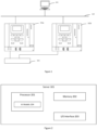
- Fig. 1 illustrates controller redundancy in a process/ industrial plant.
- the process/ industrial plant comprises one or more equipment (104). Examples of equipment includes, but are not limited to, a motor, a drive, a pump, machinery, and the like.
- the one or more equipment (104) are controlled by a primary controller (102a).
- the primary controller (102a) may be connected to the one or more equipment (104) via industry standard communication protocols, examples including but not limited to, Ethernet, RS232, and RS485.
- the primary controller (102a) may be connected to a server (101) via a network (103).
- the network (103) may support Ethernet LAN, WAN, Wi-Fi, and the like.
- the server (101) may be part of a Distributed Control System (DCS) or a Supervisory Control and Data Acquisition (SCADA) system, or a standalone system.
- the server (101) is configured to acquire data of the process/ industrial plant and perform analytics on the acquired data.
- the server (101) may acquire data of the processes, the one or more equipment (104), and the primary controller (102a).
- the server (101) may be replaced with a personal computer, a laptop, a mobile, or any other electronic device which is capable of analyzing a plurality of operational parameters of the primary controller (102a) and predicting failure condition in the primary controller (102a).
- a secondary controller (102a) is commissioned as a redundant controller in the process/ industrial plant.
- the secondary controller (102b) is used as the redundant controller.
- the secondary controller (102b) is connected to the one or more equipment (104) and to the server (101).
- the primary controller (102a) and the secondary controller (102b) may be connected via a redundancy link.
- the redundancy link may support Ethernet protocol. Other protocols known in the art may be used as the redundancy link as well.
- the switchover occurs from the primary controller(102a) to the secondary controller (102b).
- the primary controller (102a) initiates the redundancy switchover to the secondary controller (102b).
- the primary controller (102a) transfers the plurality of operational parameters and a status of the one or more equipment to the secondary controller while initiating the redundancy switchover. Therefore, when the secondary controller (102b) takes over, the operation of the process/ industrial plant can resume from where the primary controller (102a) had failed.
- reasons for failure of the primary controller (102a) can include, but not limited to, hardware faults, software faults, firmware faults, and network faults.
- the secondary controller (102b) may be connected to the server (101) via network (103) different from the network used for connecting the primary controller (102a) to the server (101). Therefore, when the primary controller (102a) has failed due to network fault, the secondary controller (102b) is secure from the network fault.
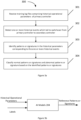
- Fig. 2 illustrates internal architecture of the server (101).
- the server comprises one or more processors (201), a memory (202) and an Input/ Output (I/O) interface (203).
- the I/O interface (203) provisions connection between the server (101), and the primary controller (102a) and the secondary controller (102b).
- the I/O interface (203) may also provision connection between the server (101) and the DCS or SCADA.
- the memory (202) stores the plurality of operational parameters of the primary equipment (102a).
- the memory (202) may be a database.
- the one or more processors (201) is configured to receive the plurality of operational parameters of the primary controller (102a) in real-time.
- the one or more processors (201) may receive the operational parameters at regular intervals.
- the one or more parameters may be time series data.
- the one or more processors (201) determines abnormal patterns or signatures in the plurality of operational parameters by comparing the plurality of operational parameters with reference patterns or signatures.
- the reference patterns or signatures are generated by one or more trained models (Al models (204)). Further, the one or more models (204) predicts one or more events that leads to failure of the primary controller (102a), which eventually leads to switchover from the primary controller (102a) to the secondary controller (102b).
- the one or more processors (201) provides a signal to the primary controller (102a) to perform a switchover from the primary controller (102a) to the secondary controller (102b) based on the predicted one or more events. Therefore, the switchover is performed even before the primary controller (102a) fails, which leads to a preventive controller switchover.
- the preventive controller switchover enable smooth switchover. Also, as the predictive controller switchover occurs before the primary controller (102a) fails, the criticality of the switchover is reduced, thus providing more efficient switchover to the secondary controller (102a).
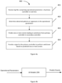
- Fig. 3a illustrates training and inference stages of one or more models (204) for generating reference patterns or signatures.
- the one or more models (204) are implemented in the server (101), and the one or more models (204) are trained to generate the reference patterns or signatures.
- the one or more models (204) receive training log files comprising historical operational parameters of the primary controller (102a).
- the training log files may be obtained from one or more historians associated with the process/ industrial plant.
- the training logs may be selected which comprises the historical operational parameters which led to the switchover from the primary controller (102a) to the secondary controller (102b).
- the one or more models (204) detect one or more historical events that led to the switchover from the primary controller (102a) to the secondary controller (102b).
- a domain expert may label the historical operational parameters with the one or more historical events.
- the one or more events are failure events in the primary controller (102a).
- the domain expert may label for few historical operational parameters and train the one or more models (204) to label for a large set of historical operational parameters. For example, the domain expert may label a first set of historical operational parameters with the label "memory fault", a second set of historical operational parameters with the label "communication port fault”, a third set of historical parameters with the label "null zero fault", a fourth set of historical operational parameters with a label "communication fault”.
- each type of controller failure may be diagnosed and a root cause may be associated.
- the failure "memory fault” may be associated with a root cause "insufficient memory”
- the failure “null zero fault” may be associated with a root cause “incorrect dynamic memory allocation”
- the failure "communication fault” may be associated with a root cause “firmware incompatibility”
- the failure "communication port fault” may be associated with the root cause "burnt port”.
- the one or more models (204) identify patterns or signatures in the historical operational parameters corresponding to the one or more historical events.
- the one or more models (204) may include, but not limited to classification models, regression models or any other type of models which are capable of determining patterns or signatures in the historical operational parameters.
- the patterns may refer to variations in the historical operational parameters before the one or more historical events occurred in the primary controller (102a). For example, there may be specific pattern in the historical operational parameters when a "memory fault' occurred. There may be specific variations in the values of the historical operational parameters that led to the "memory fault" in the primary controller.
- the one or more models (204) may require time series data to identify the patterns.
- the signatures may also be identified.
- a specific variation in the historical operational parameters may also have led to the one or more historical events. Such specific variation can be considered as signatures, which may not need time series data, but data at a specific time (for example one value of an operational parameter).
- the domain expert may have labelled few historical operational parameters while the one or more models (204) may use the labels to further label the historical operational parameters which may comprise huge data set.
- An auto-labeller may be used to label the historical operational parameters.
- the Auto-labeller may be an Al based model.
- the one or more models (204) may also determine time taken for the primary controller (102a) failed from the identified patterns or signatures.
- the one or more models (204) may map the time value against each of the one or more events.
- the one or more models (204) classifies the identified patterns or signatures into normal patterns or signatures and abnormal patterns or signatures.
- the domain expert may also label few historical operational parameters with normal patterns and abnormal patterns.
- the one or more models (204) may be trained to label the historical operational parameters with the normal patterns and the abnormal patterns using the labels provided by the domain expert.
- the abnormal patterns may be an entire region after a certain point in the time series data.
- the abnormal signature may be a point value in the historical operational parameters. It is apparent to a person skilled in the art that point values or time series data can be used to observe the abnormal signatures in the primary controller (102a).
- the classification models may be used for classifying into normal patterns and abnormal patterns.
- the normal patterns or abnormal patterns may be stored as reference patterns.
- the abnormal patterns may be stored as reference patterns.
- the normal patterns may be stored as reference patterns.
- the reference patterns are compared with real-time operational parameters of the primary controller (102a) to predict the one or more events.
- the training of the one or more models (204) is concluded when the one or more models (204) have a defined efficiency.
- Fig. 3b shows an example diagram of generating the reference patterns or signatures.
- the one or more models (204) receive the historical operational parameters as inputs.
- the one or more models (204) may also receive labels as inputs.
- the one or more models (204) may cluster the different types of events and label the clusters without the domain expert providing the labels as input.
- the one or more models (204) generate the reference patterns or signatures using the historical operational parameters as described in Fig. 3a . The reference patterns or signatures are then saved in the memory (202).
- Fig. 4a illustrates an exemplary flowchart for performing redundancy switchover in a process/ industrial plant. The following steps are performed in real-time.
- the server (101) receives log files comprising the operational parameters of the primary controller (102a) in real-time.
- the operational parameters may be received at regular time intervals (for example every 5 minutes).
- the operational parameters are received during normal operation of the primary controller (102a).
- the secondary controller (102b) is in hot stand-by.
- the operational parameters includes hardware parameters, software parameters, firmware parameters and network parameters.
- the server (101) determines abnormal patterns or signatures in the operational parameters by comparing the operational parameters with the reference patterns or signatures.
- the server (101) may compare the operational parameters with reference abnormal patterns or signatures or with reference normal patterns or signatures.
- the abnormal patterns or signatures in the operational parameters is determined when the values of the operational parameters deviate from the normal patterns or signatures.
- the abnormal patterns or signatures in the operational parameters is determined when the values of the operational parameters match the abnormal patterns or signatures.
- the server (101) predicts the one or more events leading to switchover from the primary controller (102a) to the secondary controller (102b).
- the one or more events are the events that lead to failure of the primary controller (102a).
- the one or more trained models are used to predict the one or more events.
- the one or more trained models may have associated the events with the reference patterns or the signatures.
- the one or more models (204) predicts the one or more events in real time.
- the one or more models (204) may identify abnormal patterns in operational parameters related to memory of the primary controller (102a) and predict that a memory fault may occur.
- the one or more models (204) may also predict time to failure of the primary controller (012a).
- the one or more models (204) may predict that the primary controller (102a) may fail after 5 minutes from detecting the abnormal patterns in the operational parameters related to the memory.
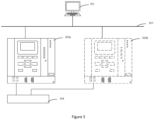
- Fig. 5 illustrates an exemplary scenario where the primary controller (102a) is operating normally and the secondary controller (102b) is in hot stand-by, while the server (101) receives the operational parameters of the primary controller (102a).
- the server (101) provides a signal to the primary controller (102a) to perform switchover to the secondary controller (102b).
- the server (101) provides the signal to the primary controller (102a) even before the primary controller (102a) fails.
- the switchover from the primary controller (102a) to the secondary controller (102b) occurs before the primary controller (102a) fails.
- the problems associated with switchover after the primary controller (102a) fails is avoided.
- the primary controller (102a) receives the signal from the serve (101) the primary controller (102a) transfers its operational parameters along with the status associated with the equipment (104). Further, the secondary controller (102b) controls the equipment (104) and the primary controller (102a) is inactive and may be scheduled for maintenance.
- a notification may be provided to indicate the one or more events.
- An operator may attend the notification and resolve the one or more events before the switchover so that the one or more events do not occur in the secondary controller (102b).
- the operational parameters of the secondary controller (102b) may be modified to avoid the one or more events from occurring in the secondary controller (102b). For example, in case of "memory fault” the operator may provide the secondary controller (102b) with additional memory. Hence, the predicted event of "memory fault” does not occur in the secondary controller (102b).
- the one or more models (204) are provided with the real-time operational parameters of the primary controller (102a). Since the one or more models (204) are trained and have generated the reference patterns or signatures, the one or more models (204) compare the operational parameters to the reference patterns or signatures. Based on the comparison, the one or more models (204) predict the one or more events (failure events) in the primary controller (102a), and the signal is provided to the primary controller (102a) to perform the preventive switchover to the secondary controller (102b) even before the primary controller (102a) fails.
- the signal provided by the server (101) enable preventive switchover from the primary controller (102a) to the secondary controller (102b).
- the fault in the primary controller (102a) does not occur, logs comprising failure events are reduced and such logs can be closed.
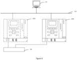
- Fig. 6 illustrates a scenario where the secondary controller (102b) controls the equipment (104) and the primary controller (102a) is inactive.
Landscapes
- Engineering & Computer Science (AREA)
- Theoretical Computer Science (AREA)
- Physics & Mathematics (AREA)
- General Physics & Mathematics (AREA)
- General Engineering & Computer Science (AREA)
- Quality & Reliability (AREA)
- Automation & Control Theory (AREA)
- Evolutionary Biology (AREA)
- Bioinformatics & Cheminformatics (AREA)
- Computing Systems (AREA)
- Computer Hardware Design (AREA)
- Bioinformatics & Computational Biology (AREA)
- Life Sciences & Earth Sciences (AREA)
- Probability & Statistics with Applications (AREA)
- Mathematical Physics (AREA)
- Chemical Kinetics & Catalysis (AREA)
- Evolutionary Computation (AREA)
- Chemical & Material Sciences (AREA)
- Artificial Intelligence (AREA)
- Testing And Monitoring For Control Systems (AREA)
- Hardware Redundancy (AREA)
- Safety Devices In Control Systems (AREA)
Description
- The present invention relates to predicting primary controller failure events and perform switchover to secondary controller.
- Process/ industrial plants comprises a plurality of equipment such as pumps, drives, air compressors, machinery, electrical appliances, etc. It is essential to operate the industrial equipment continuously to ensure maximum output of the process/ industrial plant. Current technology enables continuous operation of the equipment to reduce downtime of the equipment operation. Generally, the equipment is controlled by controllers, and due to fault in controllers, the equipment operation is halted. Typically, a redundant controller is configured as a hot stand-by which takes over the control of the equipment when a primary controller fails. The redundant controller may store all the configuration settings and parameters related to operating the equipment when switched from the primary controller. Hence, the redundant controller helps in smooth operation of the process/ industrial plant.
- In existing controller redundancy systems, the controller switchover occurs after the primary controller has failed. However, the cause of the primary controller failing may also occur in the redundant controller, thus failing the redundant controller. Also, the switchover occurs at critical time when the primary controller has actually failed. Often times, the primary controller is required to transfer status and operating parameters of the primary controller to the redundant controller. However, when the primary controller has failed, the primary controller cannot transfer all the required data to the redundant controller to efficiently control the equipment. Also, delay in switching from primary controller to redundant controller during the critical time may add to operational failure. Reference
EP 2 813 912 A1 , for example, describes a method of providing fault tolerance in an Industrial Automation and Control System IACS. Furthermore, in referenceUS 2014/9298113 A1 a storage medium and an information processing apparatus which uses failure-predictive information for management processes in a redundant system is described. Finally,CN 103 617 104 A - Hence, there is a need to provide a preventive switchover from primary controller to the redundant controller before the primary controller fails.
- In an embodiment, the present invention relates to a method, server and a system according to claims 1, 6 and 9 respectively.
- In an embodiment, the operational parameters comprises at least one of, hardware parameters, software parameters, firmware parameters and network parameters.
- In an embodiment, the one or more trained models are Artificial Intelligence (AI) based models.
- According to the invention, the server generates the reference patterns or signatures by performing the following steps. The server receives training log files comprising historical operational parameters of the primary controller. Further, the server detects one or more events which led to the switchover from the primary controller to the secondary controller using the historical operational parameters. Further, the server identifies patterns or signatures in the historical parameters in the training log files corresponding to the one or more events. Thereafter, the server classifies normal patterns or signatures and abnormal patterns or signatures based on the identified patterns or signatures, where the classified patterns are stored as reference patterns. In an embodiment, the one or more trained models determines the abnormal patterns or signatures and predicts the one or more events in real-time.
- In an embodiment, the predicted one or more events are displayed on a display unit.
- Systems of varying scope are described herein. In addition to the aspects and advantages described in this summary, further aspects and advantages will become apparent by reference to the drawings and with reference to the detailed description that follows.
- The subject matter of the invention will be explained in more detail in the following text with reference to preferred exemplary embodiments which are illustrated in the drawings, in which:
-
Fig. 1 illustrates controller redundancy in a process/ industrial plant, in accordance with some embodiments of the present invention; -
Fig. 2 illustrates internal architecture of a server for performing preventive switchover in a process/ industrial plant, in accordance with some embodiments of the present invention; -
Fig. 3a illustrates training and inference stages of models for generating reference patterns or signatures, in accordance with some embodiments of the present invention; -
Fig. 3b illustrates an exemplary diagram of generating reference patterns or signatures, in accordance with some embodiments of the present invention -
Fig. 4a illustrates an exemplary flowchart for performing redundancy switchover in a process/ industrial plant, in accordance with some embodiments of the present invention; -
Fig. 4b illustrates an exemplary diagram of predicting events in the primary controller, in accordance with some embodiments of the present invention; -
Fig. 5 illustrates an exemplary scenario of normal operation of a primary controller in a process/ industrial plant, in accordance with some embodiments of the present invention; and -
Fig. 6 illustrates an exemplary scenario of abnormal operation of a primary controller in a process/ industrial plant, in accordance with some embodiments of the present invention. - Embodiments of the present invention relates to performing preventive switchover from a primary controller to a secondary controller even before the primary controller fails. A server collects log files comprising operational parameters of the primary controller from the primary controller in real-time. Further, the server determines abnormal patterns or signatures in the operational parameters of the primary controller by comparing the operational parameters with reference patterns or signatures. The reference patterns or signatures are generated by training one or more Artificial Intelligence (AI) based models. After determining the abnormal patterns or signatures, the server predicts events that will lead to switchover from the primary controller to the secondary controller. Thereafter, the server provides a signal to the primary controller to perform preventive switchover to the secondary controller before the primary controller fails. Therefore, the abnormality in the operational parameters is notified and precaution is taken when secondary controller takes over such that the abnormalities do not occur in the secondary controller.
-
Fig. 1 illustrates controller redundancy in a process/ industrial plant. The process/ industrial plant comprises one or more equipment (104). Examples of equipment includes, but are not limited to, a motor, a drive, a pump, machinery, and the like. The one or more equipment (104) are controlled by a primary controller (102a). In an exemplary embodiment, the primary controller (102a) may be connected to the one or more equipment (104) via industry standard communication protocols, examples including but not limited to, Ethernet, RS232, and RS485. Further, the primary controller (102a) may be connected to a server (101) via a network (103). The network (103) may support Ethernet LAN, WAN, Wi-Fi, and the like. In an embodiment, the server (101) may be part of a Distributed Control System (DCS) or a Supervisory Control and Data Acquisition (SCADA) system, or a standalone system. In an embodiment, the server (101) is configured to acquire data of the process/ industrial plant and perform analytics on the acquired data. For example, the server (101) may acquire data of the processes, the one or more equipment (104), and the primary controller (102a). In an embodiment, the server (101) may be replaced with a personal computer, a laptop, a mobile, or any other electronic device which is capable of analyzing a plurality of operational parameters of the primary controller (102a) and predicting failure condition in the primary controller (102a). - In an embodiment, a secondary controller (102a) is commissioned as a redundant controller in the process/ industrial plant. In order to reduce downtime due to failure of the primary controller (102a), the secondary controller (102b) is used as the redundant controller. In an embodiment, the secondary controller (102b) is connected to the one or more equipment (104) and to the server (101). In an embodiment, the primary controller (102a) and the secondary controller (102b) may be connected via a redundancy link. The redundancy link may support Ethernet protocol. Other protocols known in the art may be used as the redundancy link as well. Conventionally, when the primary controller (102a) fails, the switchover occurs from the primary controller(102a) to the secondary controller (102b). The primary controller (102a) initiates the redundancy switchover to the secondary controller (102b). Generally, the primary controller (102a) transfers the plurality of operational parameters and a status of the one or more equipment to the secondary controller while initiating the redundancy switchover. Therefore, when the secondary controller (102b) takes over, the operation of the process/ industrial plant can resume from where the primary controller (102a) had failed. In an embodiment, reasons for failure of the primary controller (102a) can include, but not limited to, hardware faults, software faults, firmware faults, and network faults. In an embodiment, the secondary controller (102b) may be connected to the server (101) via network (103) different from the network used for connecting the primary controller (102a) to the server (101). Therefore, when the primary controller (102a) has failed due to network fault, the secondary controller (102b) is secure from the network fault.
- Reference is now made to
Fig. 2. Fig. 2 illustrates internal architecture of the server (101). The server comprises one or more processors (201), a memory (202) and an Input/ Output (I/O) interface (203). The I/O interface (203) provisions connection between the server (101), and the primary controller (102a) and the secondary controller (102b). The I/O interface (203) may also provision connection between the server (101) and the DCS or SCADA. In an embodiment, the memory (202) stores the plurality of operational parameters of the primary equipment (102a). In an embodiment, the memory (202) may be a database. In an embodiment, the one or more processors (201) is configured to receive the plurality of operational parameters of the primary controller (102a) in real-time. In an embodiment, the one or more processors (201) may receive the operational parameters at regular intervals. In one embodiment, the one or more parameters may be time series data. The one or more processors (201) determines abnormal patterns or signatures in the plurality of operational parameters by comparing the plurality of operational parameters with reference patterns or signatures. The reference patterns or signatures are generated by one or more trained models (Al models (204)). Further, the one or more models (204) predicts one or more events that leads to failure of the primary controller (102a), which eventually leads to switchover from the primary controller (102a) to the secondary controller (102b). Thereafter, the one or more processors (201) provides a signal to the primary controller (102a) to perform a switchover from the primary controller (102a) to the secondary controller (102b) based on the predicted one or more events. Therefore, the switchover is performed even before the primary controller (102a) fails, which leads to a preventive controller switchover. The preventive controller switchover enable smooth switchover. Also, as the predictive controller switchover occurs before the primary controller (102a) fails, the criticality of the switchover is reduced, thus providing more efficient switchover to the secondary controller (102a). The advantages can be realized in view of further embodiments which are explained along with examples. -
Fig. 3a illustrates training and inference stages of one or more models (204) for generating reference patterns or signatures. The one or more models (204) are implemented in the server (101), and the one or more models (204) are trained to generate the reference patterns or signatures. - At step (301) the one or more models (204) receive training log files comprising historical operational parameters of the primary controller (102a). The training log files may be obtained from one or more historians associated with the process/ industrial plant. The training logs may be selected which comprises the historical operational parameters which led to the switchover from the primary controller (102a) to the secondary controller (102b).
- At step (302) the one or more models (204) detect one or more historical events that led to the switchover from the primary controller (102a) to the secondary controller (102b). In an embodiment, a domain expert may label the historical operational parameters with the one or more historical events. The one or more events are failure events in the primary controller (102a). In an embodiment, the domain expert may label for few historical operational parameters and train the one or more models (204) to label for a large set of historical operational parameters. For example, the domain expert may label a first set of historical operational parameters with the label "memory fault", a second set of historical operational parameters with the label "communication port fault", a third set of historical parameters with the label "null zero fault", a fourth set of historical operational parameters with a label "communication fault". In an embodiment, each type of controller failure (historical events) may be diagnosed and a root cause may be associated. For example, the failure "memory fault" may be associated with a root cause "insufficient memory", the failure "null zero fault" may be associated with a root cause "incorrect dynamic memory allocation", the failure "communication fault" may be associated with a root cause "firmware incompatibility", and the failure "communication port fault" may be associated with the root cause "burnt port". The above examples should not be considered as limitations and other examples commonly known to a person skilled in the art are also envisaged with the instant invention.
- At step (303), the one or more models (204) identify patterns or signatures in the historical operational parameters corresponding to the one or more historical events. In an embodiment, the one or more models (204) may include, but not limited to classification models, regression models or any other type of models which are capable of determining patterns or signatures in the historical operational parameters. In some embodiment, the patterns may refer to variations in the historical operational parameters before the one or more historical events occurred in the primary controller (102a). For example, there may be specific pattern in the historical operational parameters when a "memory fault' occurred. There may be specific variations in the values of the historical operational parameters that led to the "memory fault" in the primary controller. The one or more models (204) may require time series data to identify the patterns. In some embodiments, the signatures may also be identified. Not always patterns may lead to the failure in the primary controller (102a). A specific variation in the historical operational parameters may also have led to the one or more historical events. Such specific variation can be considered as signatures, which may not need time series data, but data at a specific time (for example one value of an operational parameter). In one embodiment, the domain expert may have labelled few historical operational parameters while the one or more models (204) may use the labels to further label the historical operational parameters which may comprise huge data set. An auto-labeller may be used to label the historical operational parameters. The Auto-labeller may be an Al based model. In an embodiment, the one or more models (204) may also determine time taken for the primary controller (102a) failed from the identified patterns or signatures. In some embodiment, the one or more models (204) may map the time value against each of the one or more events.
- At step (304) the one or more models (204) classifies the identified patterns or signatures into normal patterns or signatures and abnormal patterns or signatures. In one embodiment, the domain expert may also label few historical operational parameters with normal patterns and abnormal patterns. The one or more models (204) may be trained to label the historical operational parameters with the normal patterns and the abnormal patterns using the labels provided by the domain expert. In an embodiment, the abnormal patterns may be an entire region after a certain point in the time series data. In an embodiment, the abnormal signature may be a point value in the historical operational parameters. It is apparent to a person skilled in the art that point values or time series data can be used to observe the abnormal signatures in the primary controller (102a). Therefore, it will also be apparent to the person skilled in the art how the Al models are trained and used for inferring the abnormal behavior of the primary controller (102a). In an embodiment, the classification models may be used for classifying into normal patterns and abnormal patterns. In an embodiment, the normal patterns or abnormal patterns may be stored as reference patterns. For example, in process/ industrial plants where the one or more historical events are certain and are known to the domain experts, the abnormal patterns may be stored as reference patterns. In process/ industrial plants where the one or more historical events are uncertain and are generally not known to the domain experts, the normal patterns may be stored as reference patterns. The reference patterns are compared with real-time operational parameters of the primary controller (102a) to predict the one or more events. In an embodiment, the training of the one or more models (204) is concluded when the one or more models (204) have a defined efficiency.
-
Fig. 3b shows an example diagram of generating the reference patterns or signatures. As shown, the one or more models (204) receive the historical operational parameters as inputs. Optionally, the one or more models (204) may also receive labels as inputs. In an embodiment, the one or more models (204) may cluster the different types of events and label the clusters without the domain expert providing the labels as input. Further, the one or more models (204) generate the reference patterns or signatures using the historical operational parameters as described inFig. 3a . The reference patterns or signatures are then saved in the memory (202). -
Fig. 4a illustrates an exemplary flowchart for performing redundancy switchover in a process/ industrial plant. The following steps are performed in real-time. - At step (401) the server (101) receives log files comprising the operational parameters of the primary controller (102a) in real-time. In an embodiment, the operational parameters may be received at regular time intervals (for example every 5 minutes). In an embodiment, the operational parameters are received during normal operation of the primary controller (102a). When the primary controller (102a) is operating normally, the secondary controller (102b) is in hot stand-by. The operational parameters includes hardware parameters, software parameters, firmware parameters and network parameters.
- At step (402) the server (101) determines abnormal patterns or signatures in the operational parameters by comparing the operational parameters with the reference patterns or signatures. In an embodiment, the server (101) may compare the operational parameters with reference abnormal patterns or signatures or with reference normal patterns or signatures. When comparing the operational parameters with normal patterns or signatures, the abnormal patterns or signatures in the operational parameters is determined when the values of the operational parameters deviate from the normal patterns or signatures. When comparing the operational parameters with abnormal patterns or signatures, the abnormal patterns or signatures in the operational parameters is determined when the values of the operational parameters match the abnormal patterns or signatures.
- At step (403) the server (101) predicts the one or more events leading to switchover from the primary controller (102a) to the secondary controller (102b). The one or more events are the events that lead to failure of the primary controller (102a). In an embodiment, the one or more trained models are used to predict the one or more events. The one or more trained models may have associated the events with the reference patterns or the signatures. Using the association, the one or more models (204) predicts the one or more events in real time. For example, the one or more models (204) may identify abnormal patterns in operational parameters related to memory of the primary controller (102a) and predict that a memory fault may occur. In an embodiment, the one or more models (204) may also predict time to failure of the primary controller (012a). For example, the one or more models (204) may predict that the primary controller (102a) may fail after 5 minutes from detecting the abnormal patterns in the operational parameters related to the memory.
Fig. 5 illustrates an exemplary scenario where the primary controller (102a) is operating normally and the secondary controller (102b) is in hot stand-by, while the server (101) receives the operational parameters of the primary controller (102a). - At step (404) the server (101) provides a signal to the primary controller (102a) to perform switchover to the secondary controller (102b). In an embodiment, the server (101) provides the signal to the primary controller (102a) even before the primary controller (102a) fails. Hence, the switchover from the primary controller (102a) to the secondary controller (102b) occurs before the primary controller (102a) fails. Thus, the problems associated with switchover after the primary controller (102a) fails is avoided. When the primary controller (102a) receives the signal from the serve (101) the primary controller (102a) transfers its operational parameters along with the status associated with the equipment (104). Further, the secondary controller (102b) controls the equipment (104) and the primary controller (102a) is inactive and may be scheduled for maintenance. In an embodiment, when the one or more models (204) predict the one or more events, a notification may be provided to indicate the one or more events. An operator may attend the notification and resolve the one or more events before the switchover so that the one or more events do not occur in the secondary controller (102b). In an embodiment, the operational parameters of the secondary controller (102b) may be modified to avoid the one or more events from occurring in the secondary controller (102b). For example, in case of "memory fault" the operator may provide the secondary controller (102b) with additional memory. Hence, the predicted event of "memory fault" does not occur in the secondary controller (102b).
- As shown in
Fig. 4b the one or more models (204) are provided with the real-time operational parameters of the primary controller (102a). Since the one or more models (204) are trained and have generated the reference patterns or signatures, the one or more models (204) compare the operational parameters to the reference patterns or signatures. Based on the comparison, the one or more models (204) predict the one or more events (failure events) in the primary controller (102a), and the signal is provided to the primary controller (102a) to perform the preventive switchover to the secondary controller (102b) even before the primary controller (102a) fails. - Therefore, the signal provided by the server (101) enable preventive switchover from the primary controller (102a) to the secondary controller (102b). In an embodiment, as the fault in the primary controller (102a) does not occur, logs comprising failure events are reduced and such logs can be closed.
Fig. 6 illustrates a scenario where the secondary controller (102b) controls the equipment (104) and the primary controller (102a) is inactive. -
- 101 - server
- 102a - primary controller
- 102b - secondary controller
- 103 - network
- 104 - equipment
- 201 - processor
- 202 - memory
- 203 - I/O interface
- 204 - Al models
Claims (12)
- A method of performing redundancy switchover in a process/ industrial plant, wherein the process/ industrial plant comprises a primary controller (102a) and a secondary controller (102b), wherein the secondary controller (102b) is redundant to the primary controller(102a), wherein the primary controller (102a) is configured to operate one or more equipment, wherein the primary controller (102a) and the secondary controller (102b) are connected to a server (101), wherein the method is performed by the server, comprising:receiving (401) log files from the primary controller (102a) in real-time, wherein the log files comprises a plurality of operational parameters of the primary controller (102a);determining (402) abnormal patterns or signatures in the plurality of operational parameters of the primary controller (102a) by comparing the plurality of operational parameters with reference patterns or signatures, wherein the reference patterns or signatures are generated based on one or more trained models (204);predicting (403) one or more events leading to a switchover from the primary controller (102a) to the secondary controller (102b) based on the abnormal patterns or signatures in the plurality of operational parameters of the primary controller (102a); and providing (404) a signal to the primary controller (102a) to perform the switchover based on the predicted one or more events, thereby performing preventive controller switchover from the primary controller (102a) to the secondary controller (102b),wherein generating the reference patterns or signatures comprises:receiving (301) training log files comprising historical operational parameters of the primary controller (102a);detecting (302) one or more historical events which led to switchover from the primary controller (102a) to the secondary controller (102b);identifying (303) patterns or signatures in the historical operational parameters in the training log files corresponding to the one or more historical events which led to the switchover;classifying (304) normal patterns or signatures and abnormal patterns or signatures based on the identified patterns or signatures, wherein the reference patterns or signatures are one of, the normal patterns or signatures or the abnormal patterns or signatures.
- The method of claim 1, wherein the plurality of operational parameters comprises at least one of, hardware parameters, software parameters, firmware parameters, and network parameters.
- The method of claim 1, wherein the one or more trained models (204) are Artificial Intelligence based models (204).
- The method of claim 1, wherein the abnormal patters or signatures are determined and the one or more events are predicted by the one or more trained models (204).
- The method of claim 1, wherein based on the predicted one or more events operational parameters of the secondary controller (102b) are modified before performing the switchover from the primary controller (102a) to the secondary controller (102b).
- A server (102b) for performing redundancy switchover in a process/ industrial plant, wherein the process/ industrial plant comprises a primary controller (102a) and a secondary controller (102b), wherein the secondary controller (102b) is redundant to the primary controller (102a), wherein the primary controller (102a) is configured to operate one or more equipment, wherein the primary controller (102a) and the secondary controller (102b) are connected to the server (102b), wherein the server comprising:a memory (202); andone or more processors (201) configured to:receive log files (401) from the primary controller (102a) in real-time, wherein the log files comprises a plurality of operational parameters of the primary controller (102a);determine (402) abnormal patterns or signatures in the plurality of operational parameters of the primary controller (102a) by comparing the plurality of operational parameters with reference patterns or signatures, wherein the reference patterns or signatures are generated based on one or more trained models (204);predict (403) one or more events leading to a switchover from the primary controller (102a) to the secondary controller (102b) based on the abnormal patterns or signatures in the plurality of operational parameters of the primary controller (102a); andprovide (404) a signal to the primary controller (102a) to perform the switchover based on the predicted one or more events, thereby performing preventive controller switchover from the primary controller (102a) to the secondary controller (102b),wherein, for generating the reference patterns or signatures, the one or more processors (201) are configured to:receive (301) training log files comprising historical operational parameters of the primary controller (102a);detect (302) one or more historical events which led to switchover from the primary controller (102a) to the secondary controller (102b);identify (303) patterns or signatures in the historical operational parameters in the training log files corresponding to the one or more historical events which led to the switchover;classify (304) normal patterns or signatures and abnormal patterns or signatures based on the identified patterns or signatures, wherein the reference patterns or signatures are one of, the normal patterns or signatures or the abnormal patterns or signatures.
- The server (102b) of claim 6, wherein the one or more trained models (204) are Artificial Intelligence based models (204).
- The sever of claim 6, wherein the one or more processors (201) are associated with a display unit to display a notification about the predicted one or more events.
- A system for performing redundancy switchover in a process/ industrial plant, the system comprising:a primary controller (102a) configured to operate one or more equipment in the process/ industrial plant;a secondary controller (102b) redundant to the primary controller (102a); anda server (102b) configured to:receive log files from the primary controller (102a) in real-time, wherein the log files comprises a plurality of operational parameters of the primary controller (102a);determine abnormal patterns or signatures in the plurality of operational parameters of the primary controller (102a) by comparing the plurality of operational parameters with reference patterns or signatures, wherein the reference patterns or signatures are generated based on one or more trained models (204);predict one or more events leading to a switchover from the primary controller (102a) to the secondary controller (102b) based on the abnormal patterns or signatures in the plurality of operational parameters; andprovide a signal to the primary controller (102a) to perform the switchover based on the predicted one or more events, thereby performing preventive controller switchover from the primary controller (102a) to the secondary controller (102b),wherein, for generating the reference patterns or signatures, the server (102b) is configured to:receive training log files comprising historical operational parameters of the primary controller (102a);detect one or more historical events which led to switchover from the primary controller (102a) to the secondary controller (102b);identify patterns or signatures in the historical operational parameters in the training log files corresponding to the one or more historical events which led to the switchover;classify normal patterns or signatures and abnormal patterns or signatures based on the identified patterns or signatures, wherein the reference patterns or signatures are one of, the normal patterns or signatures or the abnormal patterns or signatures.
- The system of claim 9, wherein the one or more trained models (204)are Artificial Intelligence based models (204).
- The system of claim 9, further comprises a display unit to display a notification about the predicted one or more events.
- The system of claim 9, wherein based on the predicted one or more events operational parameters of the secondary controller (102b) are modified before performing the switchover from the primary controller (102a) to the secondary controller (102b).
Priority Applications (3)
| Application Number | Priority Date | Filing Date | Title |
|---|---|---|---|
| EP20212782.5A EP4012515B1 (en) | 2020-12-09 | 2020-12-09 | Preventive controller switchover |
| CN202111231752.5A CN114624989B (en) | 2020-12-09 | 2021-10-22 | Preventive controller switching |
| US17/545,131 US11675685B2 (en) | 2020-12-09 | 2021-12-08 | Preventive controller switchover |
Applications Claiming Priority (1)
| Application Number | Priority Date | Filing Date | Title |
|---|---|---|---|
| EP20212782.5A EP4012515B1 (en) | 2020-12-09 | 2020-12-09 | Preventive controller switchover |
Publications (2)
| Publication Number | Publication Date |
|---|---|
| EP4012515A1 EP4012515A1 (en) | 2022-06-15 |
| EP4012515B1 true EP4012515B1 (en) | 2025-03-19 |
Family
ID=73789946
Family Applications (1)
| Application Number | Title | Priority Date | Filing Date |
|---|---|---|---|
| EP20212782.5A Active EP4012515B1 (en) | 2020-12-09 | 2020-12-09 | Preventive controller switchover |
Country Status (3)
| Country | Link |
|---|---|
| US (1) | US11675685B2 (en) |
| EP (1) | EP4012515B1 (en) |
| CN (1) | CN114624989B (en) |
Families Citing this family (1)
| Publication number | Priority date | Publication date | Assignee | Title |
|---|---|---|---|---|
| CN116827761B (en) * | 2023-08-30 | 2023-11-10 | 深圳鼎信通达股份有限公司 | Dual-machine hot standby switching method, system, equipment and medium |
Citations (1)
| Publication number | Priority date | Publication date | Assignee | Title |
|---|---|---|---|---|
| CN103617104A (en) * | 2013-12-01 | 2014-03-05 | 中国船舶重工集团公司第七一六研究所 | Active and passive redundant computer system node fault detection method based on IPMI |
Family Cites Families (12)
| Publication number | Priority date | Publication date | Assignee | Title |
|---|---|---|---|---|
| TW292365B (en) * | 1995-05-31 | 1996-12-01 | Hitachi Ltd | Computer management system |
| WO2001086775A1 (en) * | 2000-05-05 | 2001-11-15 | Aprisma Management Technologies, Inc. | Help desk systems and methods for use with communications networks |
| EP1484682B1 (en) * | 2003-06-02 | 2012-12-05 | Hewlett-Packard Development Company, L.P. | Method and apparatus for providing support for an electronic device |
| JP5949780B2 (en) * | 2011-12-19 | 2016-07-13 | 富士通株式会社 | Program, information processing apparatus and method |
| EP2813912B1 (en) * | 2013-06-14 | 2019-08-07 | ABB Schweiz AG | Fault tolerant industrial automation control system |
| JP6834446B2 (en) * | 2016-12-14 | 2021-02-24 | オムロン株式会社 | Control system, control program and control method |
| CN106814603A (en) * | 2016-12-23 | 2017-06-09 | 北京航天测控技术有限公司 | A kind of dual redundant fault-tolerant system based on non-real time operating system |
| US10279816B2 (en) * | 2017-03-07 | 2019-05-07 | GM Global Technology Operations LLC | Method and apparatus for monitoring an on-vehicle controller |
| US20180359172A1 (en) * | 2017-06-12 | 2018-12-13 | Juniper Networks, Inc. | Network path prediction and selection using machine learning |
| US10944623B2 (en) * | 2018-05-24 | 2021-03-09 | Rosemount Aerospace Inc. | Prognosis and graceful degradation of wireless aircraft networks |
| CN110703587A (en) * | 2019-10-23 | 2020-01-17 | 中船动力研究院有限公司 | Redundancy method and device for main control unit of low-speed engine for ship |
| US11513925B2 (en) * | 2020-06-24 | 2022-11-29 | EMC IP Holding Company LLC | Artificial intelligence-based redundancy management framework |
-
2020
- 2020-12-09 EP EP20212782.5A patent/EP4012515B1/en active Active
-
2021
- 2021-10-22 CN CN202111231752.5A patent/CN114624989B/en active Active
- 2021-12-08 US US17/545,131 patent/US11675685B2/en active Active
Patent Citations (1)
| Publication number | Priority date | Publication date | Assignee | Title |
|---|---|---|---|---|
| CN103617104A (en) * | 2013-12-01 | 2014-03-05 | 中国船舶重工集团公司第七一六研究所 | Active and passive redundant computer system node fault detection method based on IPMI |
Also Published As
| Publication number | Publication date |
|---|---|
| EP4012515A1 (en) | 2022-06-15 |
| CN114624989A (en) | 2022-06-14 |
| US11675685B2 (en) | 2023-06-13 |
| CN114624989B (en) | 2025-10-14 |
| US20220237100A1 (en) | 2022-07-28 |
Similar Documents
| Publication | Publication Date | Title |
|---|---|---|
| CN113614666B (en) | Systems and methods for detecting and predicting faults in industrial process automation systems | |
| US11966214B2 (en) | Industrial internet of things systems for intelligent repair of manufacturing equipment and control methods thereof | |
| CN117784765B (en) | Ship cabin diagnosis method for fault relation analysis | |
| US8914135B2 (en) | Integrated monitoring, control and equipment maintenance and tracking system | |
| JP6647824B2 (en) | Error diagnosis system and error diagnosis method | |
| CN111897671A (en) | Failure recovery method, computer device, and storage medium | |
| CN115695150B (en) | Method and device for detecting networking equipment based on distributed heterogeneous fusion | |
| US11113236B2 (en) | Method for automatic processing of a number of protocol files of an automation system | |
| WO2019209146A1 (en) | Method and system for identifying and forecasting the development of faults in equipment | |
| CN110275795A (en) | An alarm-based operation and maintenance method and device | |
| US20220365508A1 (en) | Service console log processing devices, systems, and methods | |
| KR20210109206A (en) | Intelligent condition monitoring method and system for nuclear power plants | |
| US11675685B2 (en) | Preventive controller switchover | |
| US12360173B2 (en) | Monitoring of a converter | |
| CN119227980B (en) | An artificial intelligence-based emergency plan generation method and system | |
| CN119511909A (en) | Frequency converter thermal redundancy control method, system, computer equipment and storage medium | |
| WO2000043846A2 (en) | Integration of diagnostics and control in a component-based production line | |
| CN111650898B (en) | Distributed control system and method with high fault tolerance performance | |
| Syrotkina et al. | Mathematical Methods for Detecting and Localizing Failures in Complex Hardware/Software Systems | |
| US12169403B2 (en) | Method for monitoring the vitality of devices of a distributed system | |
| CN121309265B (en) | An edge computing gateway | |
| US20250085672A1 (en) | Ai-based orchestration in industrial control systems | |
| CN115335790A (en) | Method and system for diagnosing messages | |
| CN120993087A (en) | Industrial network power supply fault diagnosis methods, devices and storage media | |
| US12085486B2 (en) | Systems and methods for container-based data collection and analysis in an operational technology network |
Legal Events
| Date | Code | Title | Description |
|---|---|---|---|
| PUAI | Public reference made under article 153(3) epc to a published international application that has entered the european phase |
Free format text: ORIGINAL CODE: 0009012 |
|
| STAA | Information on the status of an ep patent application or granted ep patent |
Free format text: STATUS: REQUEST FOR EXAMINATION WAS MADE |
|
| 17P | Request for examination filed |
Effective date: 20201209 |
|
| AK | Designated contracting states |
Kind code of ref document: A1 Designated state(s): AL AT BE BG CH CY CZ DE DK EE ES FI FR GB GR HR HU IE IS IT LI LT LU LV MC MK MT NL NO PL PT RO RS SE SI SK SM TR |
|
| RBV | Designated contracting states (corrected) |
Designated state(s): AL AT BE BG CH CY CZ DE DK EE ES FI FR GB GR HR HU IE IS IT LI LT LU LV MC MK MT NL NO PL PT RO RS SE SI SK SM TR |
|
| STAA | Information on the status of an ep patent application or granted ep patent |
Free format text: STATUS: EXAMINATION IS IN PROGRESS |
|
| 17Q | First examination report despatched |
Effective date: 20230628 |
|
| REG | Reference to a national code |
Ref country code: DE Ref legal event code: R079 Free format text: PREVIOUS MAIN CLASS: G05B0019042000 Ipc: G05B0023020000 Ref country code: DE Ref legal event code: R079 Ref document number: 602020047866 Country of ref document: DE Free format text: PREVIOUS MAIN CLASS: G05B0019042000 Ipc: G05B0023020000 |
|
| GRAP | Despatch of communication of intention to grant a patent |
Free format text: ORIGINAL CODE: EPIDOSNIGR1 |
|
| STAA | Information on the status of an ep patent application or granted ep patent |
Free format text: STATUS: GRANT OF PATENT IS INTENDED |
|
| RIC1 | Information provided on ipc code assigned before grant |
Ipc: G05B 23/02 20060101AFI20240930BHEP |
|
| INTG | Intention to grant announced |
Effective date: 20241025 |
|
| GRAS | Grant fee paid |
Free format text: ORIGINAL CODE: EPIDOSNIGR3 |
|
| GRAA | (expected) grant |
Free format text: ORIGINAL CODE: 0009210 |
|
| STAA | Information on the status of an ep patent application or granted ep patent |
Free format text: STATUS: THE PATENT HAS BEEN GRANTED |
|
| AK | Designated contracting states |
Kind code of ref document: B1 Designated state(s): AL AT BE BG CH CY CZ DE DK EE ES FI FR GB GR HR HU IE IS IT LI LT LU LV MC MK MT NL NO PL PT RO RS SE SI SK SM TR |
|
| REG | Reference to a national code |
Ref country code: GB Ref legal event code: FG4D |
|
| REG | Reference to a national code |
Ref country code: CH Ref legal event code: EP |
|
| REG | Reference to a national code |
Ref country code: IE Ref legal event code: FG4D |
|
| REG | Reference to a national code |
Ref country code: DE Ref legal event code: R096 Ref document number: 602020047866 Country of ref document: DE |
|
| PG25 | Lapsed in a contracting state [announced via postgrant information from national office to epo] |
Ref country code: RS Free format text: LAPSE BECAUSE OF FAILURE TO SUBMIT A TRANSLATION OF THE DESCRIPTION OR TO PAY THE FEE WITHIN THE PRESCRIBED TIME-LIMIT Effective date: 20250619 |
|
| PG25 | Lapsed in a contracting state [announced via postgrant information from national office to epo] |
Ref country code: FI Free format text: LAPSE BECAUSE OF FAILURE TO SUBMIT A TRANSLATION OF THE DESCRIPTION OR TO PAY THE FEE WITHIN THE PRESCRIBED TIME-LIMIT Effective date: 20250319 |
|
| REG | Reference to a national code |
Ref country code: LT Ref legal event code: MG9D |
|
| PG25 | Lapsed in a contracting state [announced via postgrant information from national office to epo] |
Ref country code: NO Free format text: LAPSE BECAUSE OF FAILURE TO SUBMIT A TRANSLATION OF THE DESCRIPTION OR TO PAY THE FEE WITHIN THE PRESCRIBED TIME-LIMIT Effective date: 20250619 |
|
| PG25 | Lapsed in a contracting state [announced via postgrant information from national office to epo] |
Ref country code: HR Free format text: LAPSE BECAUSE OF FAILURE TO SUBMIT A TRANSLATION OF THE DESCRIPTION OR TO PAY THE FEE WITHIN THE PRESCRIBED TIME-LIMIT Effective date: 20250319 |
|
| PG25 | Lapsed in a contracting state [announced via postgrant information from national office to epo] |
Ref country code: LV Free format text: LAPSE BECAUSE OF FAILURE TO SUBMIT A TRANSLATION OF THE DESCRIPTION OR TO PAY THE FEE WITHIN THE PRESCRIBED TIME-LIMIT Effective date: 20250319 |
|
| PG25 | Lapsed in a contracting state [announced via postgrant information from national office to epo] |
Ref country code: GR Free format text: LAPSE BECAUSE OF FAILURE TO SUBMIT A TRANSLATION OF THE DESCRIPTION OR TO PAY THE FEE WITHIN THE PRESCRIBED TIME-LIMIT Effective date: 20250620 Ref country code: BG Free format text: LAPSE BECAUSE OF FAILURE TO SUBMIT A TRANSLATION OF THE DESCRIPTION OR TO PAY THE FEE WITHIN THE PRESCRIBED TIME-LIMIT Effective date: 20250319 |
|
| REG | Reference to a national code |
Ref country code: NL Ref legal event code: MP Effective date: 20250319 |
|
| REG | Reference to a national code |
Ref country code: AT Ref legal event code: MK05 Ref document number: 1777440 Country of ref document: AT Kind code of ref document: T Effective date: 20250319 |
|
| PG25 | Lapsed in a contracting state [announced via postgrant information from national office to epo] |
Ref country code: NL Free format text: LAPSE BECAUSE OF FAILURE TO SUBMIT A TRANSLATION OF THE DESCRIPTION OR TO PAY THE FEE WITHIN THE PRESCRIBED TIME-LIMIT Effective date: 20250319 |
|
| PG25 | Lapsed in a contracting state [announced via postgrant information from national office to epo] |
Ref country code: SE Free format text: LAPSE BECAUSE OF FAILURE TO SUBMIT A TRANSLATION OF THE DESCRIPTION OR TO PAY THE FEE WITHIN THE PRESCRIBED TIME-LIMIT Effective date: 20250319 |
|
| PG25 | Lapsed in a contracting state [announced via postgrant information from national office to epo] |
Ref country code: SM Free format text: LAPSE BECAUSE OF FAILURE TO SUBMIT A TRANSLATION OF THE DESCRIPTION OR TO PAY THE FEE WITHIN THE PRESCRIBED TIME-LIMIT Effective date: 20250319 |
|
| PG25 | Lapsed in a contracting state [announced via postgrant information from national office to epo] |
Ref country code: ES Free format text: LAPSE BECAUSE OF FAILURE TO SUBMIT A TRANSLATION OF THE DESCRIPTION OR TO PAY THE FEE WITHIN THE PRESCRIBED TIME-LIMIT Effective date: 20250319 Ref country code: PT Free format text: LAPSE BECAUSE OF FAILURE TO SUBMIT A TRANSLATION OF THE DESCRIPTION OR TO PAY THE FEE WITHIN THE PRESCRIBED TIME-LIMIT Effective date: 20250721 |
|
| PG25 | Lapsed in a contracting state [announced via postgrant information from national office to epo] |
Ref country code: PL Free format text: LAPSE BECAUSE OF FAILURE TO SUBMIT A TRANSLATION OF THE DESCRIPTION OR TO PAY THE FEE WITHIN THE PRESCRIBED TIME-LIMIT Effective date: 20250319 Ref country code: IT Free format text: LAPSE BECAUSE OF FAILURE TO SUBMIT A TRANSLATION OF THE DESCRIPTION OR TO PAY THE FEE WITHIN THE PRESCRIBED TIME-LIMIT Effective date: 20250319 |
|
| PG25 | Lapsed in a contracting state [announced via postgrant information from national office to epo] |
Ref country code: AT Free format text: LAPSE BECAUSE OF FAILURE TO SUBMIT A TRANSLATION OF THE DESCRIPTION OR TO PAY THE FEE WITHIN THE PRESCRIBED TIME-LIMIT Effective date: 20250319 |
|
| PG25 | Lapsed in a contracting state [announced via postgrant information from national office to epo] |
Ref country code: CZ Free format text: LAPSE BECAUSE OF FAILURE TO SUBMIT A TRANSLATION OF THE DESCRIPTION OR TO PAY THE FEE WITHIN THE PRESCRIBED TIME-LIMIT Effective date: 20250319 Ref country code: EE Free format text: LAPSE BECAUSE OF FAILURE TO SUBMIT A TRANSLATION OF THE DESCRIPTION OR TO PAY THE FEE WITHIN THE PRESCRIBED TIME-LIMIT Effective date: 20250319 |
|
| PG25 | Lapsed in a contracting state [announced via postgrant information from national office to epo] |
Ref country code: RO Free format text: LAPSE BECAUSE OF FAILURE TO SUBMIT A TRANSLATION OF THE DESCRIPTION OR TO PAY THE FEE WITHIN THE PRESCRIBED TIME-LIMIT Effective date: 20250319 |
|
| PG25 | Lapsed in a contracting state [announced via postgrant information from national office to epo] |
Ref country code: SK Free format text: LAPSE BECAUSE OF FAILURE TO SUBMIT A TRANSLATION OF THE DESCRIPTION OR TO PAY THE FEE WITHIN THE PRESCRIBED TIME-LIMIT Effective date: 20250319 |
|
| PG25 | Lapsed in a contracting state [announced via postgrant information from national office to epo] |
Ref country code: IS Free format text: LAPSE BECAUSE OF FAILURE TO SUBMIT A TRANSLATION OF THE DESCRIPTION OR TO PAY THE FEE WITHIN THE PRESCRIBED TIME-LIMIT Effective date: 20250719 |
|
| REG | Reference to a national code |
Ref country code: DE Ref legal event code: R097 Ref document number: 602020047866 Country of ref document: DE |
|
| PGFP | Annual fee paid to national office [announced via postgrant information from national office to epo] |
Ref country code: DE Payment date: 20251211 Year of fee payment: 6 |
|
| PGFP | Annual fee paid to national office [announced via postgrant information from national office to epo] |
Ref country code: GB Payment date: 20251219 Year of fee payment: 6 |
|
| PG25 | Lapsed in a contracting state [announced via postgrant information from national office to epo] |
Ref country code: DK Free format text: LAPSE BECAUSE OF FAILURE TO SUBMIT A TRANSLATION OF THE DESCRIPTION OR TO PAY THE FEE WITHIN THE PRESCRIBED TIME-LIMIT Effective date: 20250319 |
|
| PLBE | No opposition filed within time limit |
Free format text: ORIGINAL CODE: 0009261 |
|
| STAA | Information on the status of an ep patent application or granted ep patent |
Free format text: STATUS: NO OPPOSITION FILED WITHIN TIME LIMIT |
|
| REG | Reference to a national code |
Ref country code: CH Ref legal event code: L10 Free format text: ST27 STATUS EVENT CODE: U-0-0-L10-L00 (AS PROVIDED BY THE NATIONAL OFFICE) Effective date: 20260128 |
|
| 26N | No opposition filed |
Effective date: 20251222 |