EP4012474B1 - Lens and lamp with lens thereof - Google Patents
Lens and lamp with lens thereof Download PDFInfo
- Publication number
- EP4012474B1 EP4012474B1 EP21193605.9A EP21193605A EP4012474B1 EP 4012474 B1 EP4012474 B1 EP 4012474B1 EP 21193605 A EP21193605 A EP 21193605A EP 4012474 B1 EP4012474 B1 EP 4012474B1
- Authority
- EP
- European Patent Office
- Prior art keywords
- light
- total reflection
- lens
- optical axis
- main optical
- Prior art date
- Legal status (The legal status is an assumption and is not a legal conclusion. Google has not performed a legal analysis and makes no representation as to the accuracy of the status listed.)
- Active
Links
Images




Classifications
-
- F—MECHANICAL ENGINEERING; LIGHTING; HEATING; WEAPONS; BLASTING
- F21—LIGHTING
- F21S—NON-PORTABLE LIGHTING DEVICES; SYSTEMS THEREOF; VEHICLE LIGHTING DEVICES SPECIALLY ADAPTED FOR VEHICLE EXTERIORS
- F21S4/00—Lighting devices or systems using a string or strip of light sources
- F21S4/20—Lighting devices or systems using a string or strip of light sources with light sources held by or within elongate supports
- F21S4/28—Lighting devices or systems using a string or strip of light sources with light sources held by or within elongate supports rigid, e.g. LED bars
-
- F—MECHANICAL ENGINEERING; LIGHTING; HEATING; WEAPONS; BLASTING
- F21—LIGHTING
- F21S—NON-PORTABLE LIGHTING DEVICES; SYSTEMS THEREOF; VEHICLE LIGHTING DEVICES SPECIALLY ADAPTED FOR VEHICLE EXTERIORS
- F21S8/00—Lighting devices intended for fixed installation
-
- F—MECHANICAL ENGINEERING; LIGHTING; HEATING; WEAPONS; BLASTING
- F21—LIGHTING
- F21V—FUNCTIONAL FEATURES OR DETAILS OF LIGHTING DEVICES OR SYSTEMS THEREOF; STRUCTURAL COMBINATIONS OF LIGHTING DEVICES WITH OTHER ARTICLES, NOT OTHERWISE PROVIDED FOR
- F21V5/00—Refractors for light sources
-
- F—MECHANICAL ENGINEERING; LIGHTING; HEATING; WEAPONS; BLASTING
- F21—LIGHTING
- F21V—FUNCTIONAL FEATURES OR DETAILS OF LIGHTING DEVICES OR SYSTEMS THEREOF; STRUCTURAL COMBINATIONS OF LIGHTING DEVICES WITH OTHER ARTICLES, NOT OTHERWISE PROVIDED FOR
- F21V5/00—Refractors for light sources
- F21V5/04—Refractors for light sources of lens shape
-
- F—MECHANICAL ENGINEERING; LIGHTING; HEATING; WEAPONS; BLASTING
- F21—LIGHTING
- F21V—FUNCTIONAL FEATURES OR DETAILS OF LIGHTING DEVICES OR SYSTEMS THEREOF; STRUCTURAL COMBINATIONS OF LIGHTING DEVICES WITH OTHER ARTICLES, NOT OTHERWISE PROVIDED FOR
- F21V5/00—Refractors for light sources
- F21V5/04—Refractors for light sources of lens shape
- F21V5/045—Refractors for light sources of lens shape the lens having discontinuous faces, e.g. Fresnel lenses
-
- F—MECHANICAL ENGINEERING; LIGHTING; HEATING; WEAPONS; BLASTING
- F21—LIGHTING
- F21V—FUNCTIONAL FEATURES OR DETAILS OF LIGHTING DEVICES OR SYSTEMS THEREOF; STRUCTURAL COMBINATIONS OF LIGHTING DEVICES WITH OTHER ARTICLES, NOT OTHERWISE PROVIDED FOR
- F21V7/00—Reflectors for light sources
- F21V7/0091—Reflectors for light sources using total internal reflection
-
- F—MECHANICAL ENGINEERING; LIGHTING; HEATING; WEAPONS; BLASTING
- F21—LIGHTING
- F21V—FUNCTIONAL FEATURES OR DETAILS OF LIGHTING DEVICES OR SYSTEMS THEREOF; STRUCTURAL COMBINATIONS OF LIGHTING DEVICES WITH OTHER ARTICLES, NOT OTHERWISE PROVIDED FOR
- F21V7/00—Reflectors for light sources
- F21V7/04—Optical design
-
- G—PHYSICS
- G02—OPTICS
- G02B—OPTICAL ELEMENTS, SYSTEMS OR APPARATUS
- G02B19/00—Condensers, e.g. light collectors or similar non-imaging optics
- G02B19/0004—Condensers, e.g. light collectors or similar non-imaging optics characterised by the optical means employed
- G02B19/0028—Condensers, e.g. light collectors or similar non-imaging optics characterised by the optical means employed refractive and reflective surfaces, e.g. non-imaging catadioptric systems
-
- G—PHYSICS
- G02—OPTICS
- G02B—OPTICAL ELEMENTS, SYSTEMS OR APPARATUS
- G02B19/00—Condensers, e.g. light collectors or similar non-imaging optics
- G02B19/0033—Condensers, e.g. light collectors or similar non-imaging optics characterised by the use
- G02B19/0047—Condensers, e.g. light collectors or similar non-imaging optics characterised by the use for use with a light source
- G02B19/0061—Condensers, e.g. light collectors or similar non-imaging optics characterised by the use for use with a light source the light source comprising a LED
-
- F—MECHANICAL ENGINEERING; LIGHTING; HEATING; WEAPONS; BLASTING
- F21—LIGHTING
- F21V—FUNCTIONAL FEATURES OR DETAILS OF LIGHTING DEVICES OR SYSTEMS THEREOF; STRUCTURAL COMBINATIONS OF LIGHTING DEVICES WITH OTHER ARTICLES, NOT OTHERWISE PROVIDED FOR
- F21V3/00—Globes; Bowls; Cover glasses
- F21V3/02—Globes; Bowls; Cover glasses characterised by the shape
-
- F—MECHANICAL ENGINEERING; LIGHTING; HEATING; WEAPONS; BLASTING
- F21—LIGHTING
- F21V—FUNCTIONAL FEATURES OR DETAILS OF LIGHTING DEVICES OR SYSTEMS THEREOF; STRUCTURAL COMBINATIONS OF LIGHTING DEVICES WITH OTHER ARTICLES, NOT OTHERWISE PROVIDED FOR
- F21V3/00—Globes; Bowls; Cover glasses
- F21V3/04—Globes; Bowls; Cover glasses characterised by materials, surface treatments or coatings
- F21V3/049—Patterns or structured surfaces for diffusing light, e.g. frosted surfaces
-
- F—MECHANICAL ENGINEERING; LIGHTING; HEATING; WEAPONS; BLASTING
- F21—LIGHTING
- F21V—FUNCTIONAL FEATURES OR DETAILS OF LIGHTING DEVICES OR SYSTEMS THEREOF; STRUCTURAL COMBINATIONS OF LIGHTING DEVICES WITH OTHER ARTICLES, NOT OTHERWISE PROVIDED FOR
- F21V31/00—Gas-tight or water-tight arrangements
-
- F—MECHANICAL ENGINEERING; LIGHTING; HEATING; WEAPONS; BLASTING
- F21—LIGHTING
- F21V—FUNCTIONAL FEATURES OR DETAILS OF LIGHTING DEVICES OR SYSTEMS THEREOF; STRUCTURAL COMBINATIONS OF LIGHTING DEVICES WITH OTHER ARTICLES, NOT OTHERWISE PROVIDED FOR
- F21V7/00—Reflectors for light sources
- F21V7/005—Reflectors for light sources with an elongated shape to cooperate with linear light sources
-
- F—MECHANICAL ENGINEERING; LIGHTING; HEATING; WEAPONS; BLASTING
- F21—LIGHTING
- F21Y—INDEXING SCHEME ASSOCIATED WITH SUBCLASSES F21K, F21L, F21S and F21V, RELATING TO THE FORM OR THE KIND OF THE LIGHT SOURCES OR OF THE COLOUR OF THE LIGHT EMITTED
- F21Y2103/00—Elongate light sources, e.g. fluorescent tubes
- F21Y2103/10—Elongate light sources, e.g. fluorescent tubes comprising a linear array of point-like light-generating elements
-
- F—MECHANICAL ENGINEERING; LIGHTING; HEATING; WEAPONS; BLASTING
- F21—LIGHTING
- F21Y—INDEXING SCHEME ASSOCIATED WITH SUBCLASSES F21K, F21L, F21S and F21V, RELATING TO THE FORM OR THE KIND OF THE LIGHT SOURCES OR OF THE COLOUR OF THE LIGHT EMITTED
- F21Y2115/00—Light-generating elements of semiconductor light sources
- F21Y2115/10—Light-emitting diodes [LED]
Definitions
- LED lamps such as bedroom, kitchen, living room and other home lighting applications and commercial lighting applications, such as in freezers, cold chains, shelves and the like.
- US 2019/011086 A1 discloses a lens-shaped light flux control member, and a light-emitting device comprising the same. A portion of the light from the light emitted by a light-emitting element enters the entrance region, then, is reflected by the first reflective surface on the same side as this entrance region with respect to the optical axis serving as a boundary, and is caused to exit from the second reflective surface on this same side.
- EP 3 037 719 A1 discloses a lens body with a light entry surface arranged centrally in a cross section and two further light entry surfaces arranged laterally thereof, wherein the light entry surfaces are arranged in such a way that a first partial light beam from at least one LED arranged centrally above the lens body enters the central light entry surface and two further partial light beams from the same LED enter in each case one of the lateral light entry surfaces, and a centrally arranged light output coupling surface, through which the first partial light beam leaves the lens body in the direction of the main radiation direction of the LED.
- the two further partial light beams are in each case totally reflected at at least one boundary surface of the lens body and leave the lens body through in each case one further light output coupling surface counter to the main radiation direction of the LED, as well as a luminaire with such a lens body.
- the second side portion comprises: a first light inlet surface; a first connecting surface, which is connected to an outer end of the first light inlet surface; a first total reflection surface, being inclined relative outwardly relative to the main optical axis in a direction extending away from the horizontal axis, if viewed in the plane where the main optical axis and the horizontal axis are located, said first total reflection surface being configured for total reflection of incident light from the first light inlet surface outwardly; a second total reflection surface, being inclined outwardly relative to the main optical axis in a direction extending away from the horizontal axis, if viewed in the plane where the main optical axis and the horizontal axis are located, a first end of said second total reflection surface being connected with a free end of the first connecting surface, said second total reflection surface being configured for receiving and reflecting the reflected light from the first total reflection surface; a third total reflection surface, being inclined inwardly relative to the main optical axis in a direction extending away from the horizontal
- the lens 100 of the present embodiment includes a light source setting portion 103, a first side portion 101 and a second side portion 102.
- the lens 100 is used to distribute and properly shape the light intensity distribution if the light emitted from the light source 200, and the light source setting portion 103 refers to the position where the light source 200 is located.
- the light source 200 may have many types of light distribution, which can be a three-dimensional 360° luminescence, or a single three-dimensional 180° luminescence, or other angles. In order to achieve an efficient and directional lighting, it is more advantageous to use a single three-dimensional 180° luminescence for secondary lighting. Therefore, the light source 200 in this embodiment is a single-sided, three-dimensional luminescence of 180°.
- the most common such light source 200 is an LED chip with a circuit board and its maximum light intensity direction is vertical to the circuit board.
- the light source setting portion 103 is defined with a main optical axis 104, a longitudinal axis 105 and a horizontal axis 106 passing through its center and extending perpendicular to each other.
- the light source 200 has a maximum light intensity direction that coincides with the main optical axis 104.
- the second side portion 102 deflects light from the light source 200 on its side towards the first side portion 101, and the second side portion 102 includes a first light inlet surface 1021, a first connecting surface 1022, a first total reflection surface 1023, a second total reflection surface 1024, a third total reflection surface 1025 and a first light outlet surface 1026.
- the first light inlet surface 1021 receives the light beam from the light source 200, and the first connecting surface 1022 is connected to the outer end of the first light inlet surface 1021.
- the first connecting surface 1022 is used for transition and connection and does not participate in modifying the main lighting distribution, and its shape is related to the shape of other light distribution surfaces.
- the first side portion 101 and the second side portion 102 are integrally formed in this embodiment, and the connecting line is located at the main optical axis 104.
Landscapes
- Engineering & Computer Science (AREA)
- General Engineering & Computer Science (AREA)
- Physics & Mathematics (AREA)
- General Physics & Mathematics (AREA)
- Optics & Photonics (AREA)
- Non-Portable Lighting Devices Or Systems Thereof (AREA)
- Lenses (AREA)
Description
- The present invention relates to the field of lighting techniques, in particular to a lens and a lamp comprising such a lens.
- With the popularity of LED lamps, there are more and more occasions to start using LED lamps, such as bedroom, kitchen, living room and other home lighting applications and commercial lighting applications, such as in freezers, cold chains, shelves and the like.
- An LED chip can be used as a point-like light source with a certain (fixed) light intensity distribution, but for practical use, focus or uniform illumination over a large area is required. Therefore, in the prior art, optical elements are generally disposed in the LED chip light direction for secondary light distribution, so as to achieve the required light intensity distribution.
- With the development of lighting technology, new requirements have also been put forward. In indoor lighting, especially in products such as freezers and shelves, which are often located in corner locations, efficient single-side large-area lighting is required, and miniaturization of the volume is also required. At present, the existing lamps cannot meet the needs.
-
US 2019/011086 A1 discloses a lens-shaped light flux control member, and a light-emitting device comprising the same. A portion of the light from the light emitted by a light-emitting element enters the entrance region, then, is reflected by the first reflective surface on the same side as this entrance region with respect to the optical axis serving as a boundary, and is caused to exit from the second reflective surface on this same side. Another portion of the light enters the entrance region, is reflected by the second reflective surface and the third reflective surface, in this order, on the same side as this entrance region with respect to the optical axis serving as the boundary, is then caused to exit from the connection surface on this same side, re-enters from the first reflective surface or the connection surface on the opposite side with respect to the optical axis, and is then caused to exit from the second reflective surface on this opposite side. -
EP 3 037 719 A1 discloses a lens body with a light entry surface arranged centrally in a cross section and two further light entry surfaces arranged laterally thereof, wherein the light entry surfaces are arranged in such a way that a first partial light beam from at least one LED arranged centrally above the lens body enters the central light entry surface and two further partial light beams from the same LED enter in each case one of the lateral light entry surfaces, and a centrally arranged light output coupling surface, through which the first partial light beam leaves the lens body in the direction of the main radiation direction of the LED. The two further partial light beams are in each case totally reflected at at least one boundary surface of the lens body and leave the lens body through in each case one further light output coupling surface counter to the main radiation direction of the LED, as well as a luminaire with such a lens body. - It is an object of the present invention to provide a lens and a lamp with such a lens, wherein the lens is configured to realize uniform lighting in a large area on one side, and has small volume and high light efficiency.
- This problem is solved by a lens as claimed by claim 1, and by a lamp as claimed by claim 11. Further advantageous embodiments are the subject-matter of the dependent claims.
- A lens according to the present invention comprises: a light source setting portion with a main optical axis, a longitudinal axis and a horizontal axis passing through its center and perpendicular to each other; said lens being divided into a first side portion and second side portion, in a plane where the main optical axis and the horizontal axis are located, which are disposed on opposite sides of the main optical axis, wherein the first side portion is configured to deflect light from a light source disposed at the light source setting portion and having a maximum light intensity direction that coincides with the main optical axis in a direction away from the second side portion and such that a reverse extension line of the maximum light intensity direction of the first beam after deflection by the first side portion intersects the main optical axis. According to the present invention the second side portion comprises: a first light inlet surface; a first connecting surface, which is connected to an outer end of the first light inlet surface; a first total reflection surface, being inclined relative outwardly relative to the main optical axis in a direction extending away from the horizontal axis, if viewed in the plane where the main optical axis and the horizontal axis are located, said first total reflection surface being configured for total reflection of incident light from the first light inlet surface outwardly; a second total reflection surface, being inclined outwardly relative to the main optical axis in a direction extending away from the horizontal axis, if viewed in the plane where the main optical axis and the horizontal axis are located, a first end of said second total reflection surface being connected with a free end of the first connecting surface, said second total reflection surface being configured for receiving and reflecting the reflected light from the first total reflection surface; a third total reflection surface, being inclined inwardly relative to the main optical axis in a direction extending away from the horizontal axis, if viewed in the plane where the main optical axis and the horizontal axis are located, one end of the third total reflection surface being connected with a second end of the second total reflection surface opposite to the first end of the second total reflection surface, said third total reflection surface being configured for total reflection of the reflected light from the second total reflection surface; and a first light outlet surface, being connected to the free end of the first total reflection surface and the third total reflection surface, and being configured for emitting the reflected light from the third total reflection surface; wherein the second light beam emitted from the first light outlet surface has a maximum light intensity direction intersecting with the main optical axis.
- The lens of the present invention and the lamp with the lens realizes uniform lighting in a large area on one side, and has small volume and high light efficiency.
- Exemplary embodiments of the present invention will be described below with reference to the drawings, in which:
- FIG. 1
- is a three-dimensional structure diagram of the lens of the present embodiment;
- FIG.2
- is a schematic cross-sectional view of the lens of the present embodiment;
- FIG.3
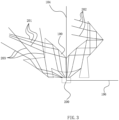
- is an optical path diagram of the lens of the present embodiment;
- FIG.4
- is an optical path diagram of the lens of the present embodiment showing also the illumination surface; and
- FIG.5
- is a structural diagram of a lamp according to the present embodiment comprising a lens according to the present invention.
- Specific embodiments of the present invention will be described in further detail below based on the drawings. It should be understood that the description of the embodiments of the present invention herein is not intended to limit the protection scope of the present invention.
- As shown in
FIGs. 1 to 4 , thelens 100 of the present embodiment includes a lightsource setting portion 103, afirst side portion 101 and asecond side portion 102. Thelens 100 is used to distribute and properly shape the light intensity distribution if the light emitted from thelight source 200, and the lightsource setting portion 103 refers to the position where thelight source 200 is located. Thelight source 200 may have many types of light distribution, which can be a three-dimensional 360° luminescence, or a single three-dimensional 180° luminescence, or other angles. In order to achieve an efficient and directional lighting, it is more advantageous to use a single three-dimensional 180° luminescence for secondary lighting. Therefore, thelight source 200 in this embodiment is a single-sided, three-dimensional luminescence of 180°. At present the most commonsuch light source 200 is an LED chip with a circuit board and its maximum light intensity direction is vertical to the circuit board. For convenience of description, the lightsource setting portion 103 is defined with a mainoptical axis 104, alongitudinal axis 105 and ahorizontal axis 106 passing through its center and extending perpendicular to each other. In general, thelight source 200 has a maximum light intensity direction that coincides with the mainoptical axis 104. - The
lens 100 of the present invention is divided into afirst side portion 101 and asecond side portion 102, in the plane where the mainoptical axis 104 and thehorizontal axis 106 are located, and on each side of the mainoptical axis 104, respectively. The light from thelight source 200 arranged at the lightsource setting portion 103 forms afirst light beam 201 after modification of the light distribution by means of thefirst side portion 101, and the reverse extension line of the maximum light intensity direction of thefirst light beam 201 intersects the mainoptical axis 104. Thefirst side portion 101 deflects light from thelight source 200 on its side in a direction away from thesecond side portion 102. The specific shape and structure can be configured according to the desired deflection angle and beam angle. - When a high-efficiency single-sided illumination is required, the
second side portion 102 deflects light from thelight source 200 on its side towards thefirst side portion 101, and thesecond side portion 102 includes a firstlight inlet surface 1021, a first connectingsurface 1022, a firsttotal reflection surface 1023, a secondtotal reflection surface 1024, a thirdtotal reflection surface 1025 and a firstlight outlet surface 1026. The firstlight inlet surface 1021 receives the light beam from thelight source 200, and the first connectingsurface 1022 is connected to the outer end of the firstlight inlet surface 1021. The first connectingsurface 1022 is used for transition and connection and does not participate in modifying the main lighting distribution, and its shape is related to the shape of other light distribution surfaces. The firsttotal reflection surface 1023 is arranged with an outward tilt relative to the mainoptical axis 104, and is used (configured) to for total reflection of the incident light from the firstlight inlet surface 1011 outwardly. The consistency of the light beam from thelight source 200 is usually not good enough, and the firsttotal reflection surface 1023 is a curved surface that improves the consistency of the light beam. The secondtotal reflection surface 1024 is inclined outwardly relative to the mainoptical axis 104, and one end thereof is connected with the free end of the first connectingsurface 1022, configured for receiving and total reflection of the reflected light from the firsttotal reflection surface 1023. The thirdtotal reflection surface 1025 is inclined inwardly relative to the mainoptical axis 104, and one end thereof is connected with the free end of the secondtotal reflection surface 1024, and it is configured for total reflection of the reflected light from the secondtotal reflection surface 1024. A part (portion) of the light beam from thelight source 200 on the side where thesecond side portion 102 is located is deflected by the three afore-mentioned total reflection surfaces and finally emitted via the firstlight outlet surface 1026. The firstlight outlet surface 1026 is connected to the free end of the firsttotal reflection surface 1023 and the thirdtotal reflection surface 1025, and the maximum light intensity direction of thesecond light beam 202 emitted from the firstlight outlet surface 1026 intersects with the mainoptical axis 104. - The light inlet and outlet surfaces of the
first side portion 101 are both condenser surfaces and can also realize a deflection of the light beam, but not only uneven and the deflection angle cannot be very large, it is difficult to achieve a large range of lighting. In this embodiment, thefirst side portion 101 includes a secondlight inlet surface 1011, a second connectingsurface 1012, a fourthtotal reflection surface 1013, a secondlight outlet surface 1014, a fifthtotal reflection surface 1015, and a thirdlight outlet surface 1016. The second connectingsurface 1012 is connected with the outer end of the secondlight inlet surface 1011. Similarly, the second connectingsurface 1012 is used for transition and connection, and does not participate in modification of the main light intensity distribution. Its shape is related to the shape of other light distribution surfaces. The fourthtotal reflection surface 1013 is inclined outwardly relative to the mainoptical axis 104, and is used for total reflection of the incident light from the secondlight inlet surface 1021 that is near the mainoptical axis 104 to the outside. In order to make the light more consistent, more uniform on the irradiation surface, the fourthtotal reflection surface 1013 is a curved surface to improve the consistency of the light beam. The secondlight outlet surface 1014 is used for emitting the reflected light from the fourthtotal reflection surface 1013 to form afirst light beam 201. The fifthtotal reflection surface 1015 is inclined outwardly relative to the mainoptical axis 104, and one end thereof is connected with the free end of the second connectingsurface 1012, and the incident light from the secondlight inlet surface 1021 that is away from the mainoptical axis 104 is totally reflected to form a reflected light near the mainoptical axis 104. A thirdlight outlet surface 1016 is located above the fifthtotal reflection surface 1015 for emitting the reflected light which is from the fifthtotal reflection surface 1015 to form a thirdlight beam 203. Thefirst side portion 101 deflects the incident light near the mainoptical axis 104 outward to obtain thefirst light beam 201, which is used for large-area illumination, and a large angle deflection can be achieved by the afore-mentioned total reflection. In addition, in order to compensate for the illumination oflens 100 in the direction of mainoptical axis 104, in this embodiment, incident light from the secondlight inlet surface 1021 away from the mainoptical axis 104 is reflected by the fifthtotal reflection surface 1015. - In order to increase the light efficiency, in the present embodiment, the first
light inlet surface 1021 is a light collecting surface. The secondlight inlet surface 1011 near the mainoptical axis 104 is a light collecting surface, and the part away from the mainoptical axis 104 is the side wall of the counter bore 107. The arrangement of the counter bore 107 can improve the light efficiency, which is not described in conventional settings. - In order to improve optical efficiency, in this embodiment, the maximum light intensity directions of the second
light beam 202 and the lightfirst beam 201 are parallel or intersect at an angle of less than 5°. - The included angle between the reverse extension line of the maximum light intensity direction of the
first light beam 201 and the mainoptical axis 104 is 60 ° to 80 °. - In order to facilitate manufacturing and light distribution calculation, the
first side portion 101 and thesecond side portion 102 are integrally formed in this embodiment, and the connecting line is located at the mainoptical axis 104. - With the
lens 100 of the present embodiment theillumination surface 600 will receive a wide range of uniform illumination on a single side. - The invention is mainly used for light distribution of line-shaped light source, and the
lens 100 is a strip-shaped lens extending along thelongitudinal axis 105. - As shown in
FIG.5 , the lamp in this embodiment includes alamp holder 300, alens 100 and alight source 200, and thelight source 200 is arranged on (at) the lightsource setting portion 103. Thelamp holder 300 is a strip-shaped lamp holder extending along thelongitudinal axis 105, thelens 100 is a strip-shaped lens extending along thelongitudinal axis 105, and thelight source 200 is a linear light source extending along thelongitudinal axis 105. The lamp also comprises alamp cover 400 arranged on thelamp holder 300 and located above thelens 100. Anoptical film 500, stretching the light from thelight source 200 along thelongitudinal axis 105, is arranged between thelens 100 and thelamp cover 400. Thelight source 200 includes a strip-shapedcircuit board 204 extending along thelongitudinal axis 105 and a plurality ofLED chips 205 arranged on the strip-shapedcircuit board 204. - The
lamp holder 300 is a strip-shaped lamp holder extending along thelongitudinal axis 105, thelens 100 is a strip-shaped lens extending along thelongitudinal axis 105, and thelight source 200 is a linear light source extending along thelongitudinal axis 105. The lamp also comprises alamp cover 400 arranged on thelamp holder 300 and located above thelens 100. Anoptical film 500, stretching the light from thelight source 200 along thelongitudinal axis 105, is arranged between thelens 100 and thelamp cover 400. Thelight source 200 includes a strip-shapedcircuit board 204 extending along thelongitudinal axis 105 and a plurality ofLED chips 205 arranged on the strip-shapedcircuit board 204. - The above are only preferred embodiments of the present invention, and are not used to limit the protection scope of the present invention.
Claims (14)
- A lens (100), comprising:a light source setting portion (103) with a main optical axis (104), a longitudinal axis (105) and a horizontal axis (106) passing through its center and perpendicular to each other; said lens (100) being divided into a first side portion (101) and second side portion (102), in a plane where the main optical axis (104) and the horizontal axis (106) are located, which are disposed on opposite sides of the main optical axis (104), whereinthe first side portion (101) is configured to deflect light from a light source (200) disposed at the light source setting portion (103) and having a maximum light intensity direction that coincides with the main optical axis in a direction away from the second side portion (102) and such that a reverse extension line of the maximum light intensity direction of the first beam (201) after deflection by the first side portion (101) intersects the main optical axis (104);characterized in that the second side portion (102) comprises:a first light inlet surface (1021);a first connecting surface (1022), which is connected to an outer end of the first light inlet surface (1021);a first total reflection surface (1023), being inclined outwardly relative to the main optical axis (104) in a direction extending away from the horizontal axis (106), if viewed in the plane where the main optical axis (104) and the horizontal axis (106) are located, said first total reflection surface (1023) being configured for total reflection of incident light from the first light inlet surface (1011) outwardly;a second total reflection surface (1024), being inclined outwardly relative to the main optical axis (104) in a direction extending away from the horizontal axis (106), if viewed in the plane where the main optical axis (104) and the horizontal axis (106) are located, a first end of said second total reflection surface (1024) being connected with a free end of the first connecting surface (1022), said second total reflection surface (1024) being configured for receiving and reflecting the reflected light from the first total reflection surface (1023);a third total reflection surface (1025), being inclined inwardly relative to the main optical axis (104) in a direction extending away from the horizontal axis (106), if viewed in the plane where the main optical axis (104) and the horizontal axis (106) are located, one end of the third total reflection surface (1025) being connected with a second end of the second total reflection surface (1024) opposite to the first end of the second total reflection surface (1024), said third total reflection surface (1025) being configured for total reflection of the reflected light from the second total reflection surface (1024); anda first light outlet surface (1026), being connected to the free end of the first total reflection surface (1023) and the third total reflection surface (1025), and being configured for emitting the reflected light from the third total reflection surface (1025); whereinthe second light beam (202) emitted from the first light outlet surface (1026) has a maximum light intensity direction intersecting with the main optical axis (104).
- The lens (100) as claimed in claim 1, wherein the first side portion (101) comprises:a second light inlet surface (1011);a second connecting surface (1012), being connected with an outer end of the second light inlet surface (1011);a fourth total reflection surface (1013), being inclined outwardly relative to the main optical axis (104) in a direction extending away from the horizontal axis (106), if viewed in the plane where the main optical axis (104) and the horizontal axis (106) are located, said fourth total reflection surface (1013) being configured for total reflection of the incident light from a portion of the second light inlet surface (1021) that is near the main optical axis (104) to the outside;a second light outlet surface (1014), for emitting reflected light from the fourth total reflection surface (1013) to form a first light beam (201);a fifth total reflection surface (1015), being inclined outwardly relative to the main optical axis (104) in a direction extending away from the horizontal axis (106), if viewed in the plane where the main optical axis (104) and the horizontal axis (106) are located, one end of the fifth total reflection surface (1015) being connected with the free end of the second connecting surface (1012), for total reflection of incident light from the second light inlet surface (1021) away from the main optical axis (104) to form a reflected light close to the main optical axis (104); anda third light outlet surface (1016), located above the fifth total reflection surface (1015), for emitting reflected light is from the fifth total reflection surface (1015) to form a third beam (203).
- The lens (100) as claimed in claim 1 or 2, wherein the first light inlet surface (1021) is a light collecting surface.
- The lens (100) as claimed in any of the preceding claims, wherein at least a portion of the second light inlet surface (1011) near the main optical axis (104) is a light collecting or focusing surface.
- The lens (100) as claimed in any of the preceding claims, wherein the first total reflection surface (1023) is a curved surface, for improving a consistency of the light beam.
- The lens (100) as claimed in any of the preceding claims, wherein the fourth total reflection surface (1013) is a curved surface, for improving consistency of the light beam.
- A lens (100) as claimed in any of the preceding claims, wherein the maximum light intensity directions of the second light beam (202) and the first light beam (201) are parallel or intersect at an angle less than 5°.
- The lens (100) as claimed in any of claims 1 to 6, wherein the included angle between the reverse extension line of the maximum light intensity direction of the first light beam (201) and the main optical axis (104) is 60 ° to 80 °.
- The lens (100) as claimed in any of the preceding claims, wherein the first side portion (101) and the second side portion (102) are integrally formed, and the connecting line is located at the main optical axis (104).
- The lens (100) as claimed in any of the preceding claims, wherein the lens (100) is a strip lens or bar-shaped lens extending along a longitudinal axis (105).
- A lamp, comprising a lamp holder (300), a lens (100), and a light source (200), characterized in that the lens (100) comprises the lens (100) as claimed in any of claims 1 to 10, wherein the light source (200) is arranged on or at the light source setting portion (103).
- The lamp as claimed in claim 11, whereinthe lamp holder (300) is a strip-shaped lamp holder extending along the longitudinal axis (105),the lens (100) is a strip-shaped lens extending along the longitudinal axis (105), andthe light source (200) is a linear source extending along the longitudinal axis (105).
- The lamp as claimed in claim 11 or 12, wherein the lamp further comprises a lamp cover (400) arranged on the lamp holder (300) and located above the lens (100).
- The lamp as claimed in any of claims 11 to 13, wherein an optical film (500) for stretching the light from the light source (200) along the longitudinal axis (105) is disposed between the lens (100) and the lamp cover (400).
Applications Claiming Priority (1)
| Application Number | Priority Date | Filing Date | Title |
|---|---|---|---|
| CN202011447057.8A CN112483939B (en) | 2020-12-11 | 2020-12-11 | Lens and lamp with the same |
Publications (2)
| Publication Number | Publication Date |
|---|---|
| EP4012474A1 EP4012474A1 (en) | 2022-06-15 |
| EP4012474B1 true EP4012474B1 (en) | 2024-07-10 |
Family
ID=74941566
Family Applications (1)
| Application Number | Title | Priority Date | Filing Date |
|---|---|---|---|
| EP21193605.9A Active EP4012474B1 (en) | 2020-12-11 | 2021-08-27 | Lens and lamp with lens thereof |
Country Status (3)
| Country | Link |
|---|---|
| US (1) | US20220186909A1 (en) |
| EP (1) | EP4012474B1 (en) |
| CN (1) | CN112483939B (en) |
Families Citing this family (4)
| Publication number | Priority date | Publication date | Assignee | Title |
|---|---|---|---|---|
| US11666045B2 (en) * | 2021-01-04 | 2023-06-06 | Robert Joseph Marques | Submersible illuminating apparatus |
| CN114427673A (en) * | 2021-12-31 | 2022-05-03 | 赛尔富电子有限公司 | Lens and illumination method |
| CN114811522B (en) * | 2022-05-23 | 2025-11-21 | 欧普照明股份有限公司 | Polarized lens and lighting lamp |
| CN115930159A (en) * | 2022-12-22 | 2023-04-07 | 赛尔富电子有限公司 | a lighting lens |
Family Cites Families (16)
| Publication number | Priority date | Publication date | Assignee | Title |
|---|---|---|---|---|
| US7967477B2 (en) * | 2007-09-06 | 2011-06-28 | Philips Lumileds Lighting Company Llc | Compact optical system and lenses for producing uniform collimated light |
| JP2010224089A (en) * | 2009-03-23 | 2010-10-07 | Brother Ind Ltd | Prism |
| US8465190B2 (en) * | 2009-05-22 | 2013-06-18 | Sylvan R. Shemitz Designs Incorporated | Total internal reflective (TIR) optic light assembly |
| JP5518559B2 (en) * | 2010-04-22 | 2014-06-11 | スタンレー電気株式会社 | Lamp unit |
| CN103672729B (en) * | 2012-09-13 | 2016-12-21 | 赛尔富电子有限公司 | Lens, LED module and use the illuminator of this LED module |
| CN105318275B (en) * | 2014-07-31 | 2019-03-12 | 欧普照明股份有限公司 | A lens and asymmetric light distribution lighting device with the lens |
| DE102014119616A1 (en) * | 2014-12-23 | 2016-06-23 | Siteco Beleuchtungstechnik Gmbh | LED lens body for generating a direct and indirect light component |
| JP6541126B2 (en) * | 2015-06-29 | 2019-07-10 | 株式会社エンプラス | Light flux control member, light emitting device and lighting device |
| TWI554724B (en) * | 2015-11-12 | 2016-10-21 | 國立臺灣科技大學 | Total internal reflection lens |
| CN107654860B (en) * | 2017-10-31 | 2024-03-29 | 欧普道路照明有限公司 | Lens combination, light source module and lighting device |
| CN110529823A (en) * | 2019-06-19 | 2019-12-03 | 赛尔富电子有限公司 | A kind of optical element and the headlamp with the optical element |
| CN110285335A (en) * | 2019-06-19 | 2019-09-27 | 赛尔富电子有限公司 | An optical element and a lamp with the optical element |
| CN209801374U (en) * | 2019-07-05 | 2019-12-17 | 深圳市希尔光学技术有限公司 | Polarizing lens with large deflection angle and lamp |
| CN110886983A (en) * | 2019-11-07 | 2020-03-17 | 赛尔富电子有限公司 | a lighting lamp |
| CN111706830A (en) * | 2020-07-24 | 2020-09-25 | 深圳爱克莱特科技股份有限公司 | Double polarized LED lens and LED lens module |
| CN215636690U (en) * | 2020-12-11 | 2022-01-25 | 赛尔富电子有限公司 | A lens and a lamp with the lens |
-
2020
- 2020-12-11 CN CN202011447057.8A patent/CN112483939B/en active Active
-
2021
- 2021-08-25 US US17/445,853 patent/US20220186909A1/en not_active Abandoned
- 2021-08-27 EP EP21193605.9A patent/EP4012474B1/en active Active
Also Published As
| Publication number | Publication date |
|---|---|
| EP4012474A1 (en) | 2022-06-15 |
| CN112483939A (en) | 2021-03-12 |
| US20220186909A1 (en) | 2022-06-16 |
| CN112483939B (en) | 2025-08-08 |
Similar Documents
| Publication | Publication Date | Title |
|---|---|---|
| EP4012474A1 (en) | Lens and lamp with lens thereof | |
| EP2467637B1 (en) | A lighting device and a lens suitable for such a lighting device | |
| US20050024744A1 (en) | Circumferentially emitting luminaires and lens-elements formed by transverse-axis profile-sweeps | |
| US20040105262A1 (en) | LED light source with reflecting side wall | |
| CN102498338B (en) | Lighting device | |
| EP3754248B1 (en) | Optical element and lighting lamp with the same | |
| US20220034463A1 (en) | Multi-beam vehicle light | |
| CN108253381B (en) | Lens and light-emitting device comprising same | |
| EP2034237B1 (en) | Energy-saving lampshade with even light distribution | |
| CN107504421A (en) | Vehicle lighting means | |
| CN206093924U (en) | Reflector and light source module | |
| US8646961B2 (en) | Reflective plate, planar lamp and planar lamp fixture including the same | |
| CN105333397B (en) | A polarizing lens and lighting fixture having the polarizing lens | |
| CN102798079A (en) | A lamp cup for LED lamp | |
| CN215636690U (en) | A lens and a lamp with the lens | |
| CN210801025U (en) | Optical element and illuminating lamp with same | |
| CN209540791U (en) | A kind of combined type optical texture and its lamps and lanterns | |
| EP4530524A1 (en) | Led optical system capable of uniformly emitting light, and lamp | |
| CN220436321U (en) | An optical lens, lighting device and operating light | |
| CN107489986A (en) | Reflector and light source module | |
| CN216952912U (en) | Lens and bias light distribution lamp | |
| CN213178196U (en) | Illumination lens subassembly and cut-off type lamps and lanterns | |
| CN210800738U (en) | Optical element and lamp with same | |
| CN222911443U (en) | Optical system and lamp with small hole light output | |
| CN224246001U (en) | Lens and lamp |
Legal Events
| Date | Code | Title | Description |
|---|---|---|---|
| PUAI | Public reference made under article 153(3) epc to a published international application that has entered the european phase |
Free format text: ORIGINAL CODE: 0009012 |
|
| STAA | Information on the status of an ep patent application or granted ep patent |
Free format text: STATUS: THE APPLICATION HAS BEEN PUBLISHED |
|
| AK | Designated contracting states |
Kind code of ref document: A1 Designated state(s): AL AT BE BG CH CY CZ DE DK EE ES FI FR GB GR HR HU IE IS IT LI LT LU LV MC MK MT NL NO PL PT RO RS SE SI SK SM TR |
|
| STAA | Information on the status of an ep patent application or granted ep patent |
Free format text: STATUS: REQUEST FOR EXAMINATION WAS MADE |
|
| 17P | Request for examination filed |
Effective date: 20221214 |
|
| RBV | Designated contracting states (corrected) |
Designated state(s): AL AT BE BG CH CY CZ DE DK EE ES FI FR GB GR HR HU IE IS IT LI LT LU LV MC MK MT NL NO PL PT RO RS SE SI SK SM TR |
|
| GRAP | Despatch of communication of intention to grant a patent |
Free format text: ORIGINAL CODE: EPIDOSNIGR1 |
|
| STAA | Information on the status of an ep patent application or granted ep patent |
Free format text: STATUS: GRANT OF PATENT IS INTENDED |
|
| INTG | Intention to grant announced |
Effective date: 20240415 |
|
| GRAS | Grant fee paid |
Free format text: ORIGINAL CODE: EPIDOSNIGR3 |
|
| GRAA | (expected) grant |
Free format text: ORIGINAL CODE: 0009210 |
|
| STAA | Information on the status of an ep patent application or granted ep patent |
Free format text: STATUS: THE PATENT HAS BEEN GRANTED |
|
| AK | Designated contracting states |
Kind code of ref document: B1 Designated state(s): AL AT BE BG CH CY CZ DE DK EE ES FI FR GB GR HR HU IE IS IT LI LT LU LV MC MK MT NL NO PL PT RO RS SE SI SK SM TR |
|
| REG | Reference to a national code |
Ref country code: CH Ref legal event code: EP |
|
| REG | Reference to a national code |
Ref country code: DE Ref legal event code: R096 Ref document number: 602021015379 Country of ref document: DE |
|
| REG | Reference to a national code |
Ref country code: LT Ref legal event code: MG9D |
|
| REG | Reference to a national code |
Ref country code: NL Ref legal event code: MP Effective date: 20240710 |
|
| PG25 | Lapsed in a contracting state [announced via postgrant information from national office to epo] |
Ref country code: PT Free format text: LAPSE BECAUSE OF FAILURE TO SUBMIT A TRANSLATION OF THE DESCRIPTION OR TO PAY THE FEE WITHIN THE PRESCRIBED TIME-LIMIT Effective date: 20241111 |
|
| REG | Reference to a national code |
Ref country code: AT Ref legal event code: MK05 Ref document number: 1702546 Country of ref document: AT Kind code of ref document: T Effective date: 20240710 |
|
| PG25 | Lapsed in a contracting state [announced via postgrant information from national office to epo] |
Ref country code: NL Free format text: LAPSE BECAUSE OF FAILURE TO SUBMIT A TRANSLATION OF THE DESCRIPTION OR TO PAY THE FEE WITHIN THE PRESCRIBED TIME-LIMIT Effective date: 20240710 |
|
| PG25 | Lapsed in a contracting state [announced via postgrant information from national office to epo] |
Ref country code: PT Free format text: LAPSE BECAUSE OF FAILURE TO SUBMIT A TRANSLATION OF THE DESCRIPTION OR TO PAY THE FEE WITHIN THE PRESCRIBED TIME-LIMIT Effective date: 20241111 Ref country code: NL Free format text: LAPSE BECAUSE OF FAILURE TO SUBMIT A TRANSLATION OF THE DESCRIPTION OR TO PAY THE FEE WITHIN THE PRESCRIBED TIME-LIMIT Effective date: 20240710 |
|
| PG25 | Lapsed in a contracting state [announced via postgrant information from national office to epo] |
Ref country code: NO Free format text: LAPSE BECAUSE OF FAILURE TO SUBMIT A TRANSLATION OF THE DESCRIPTION OR TO PAY THE FEE WITHIN THE PRESCRIBED TIME-LIMIT Effective date: 20241010 |
|
| PG25 | Lapsed in a contracting state [announced via postgrant information from national office to epo] |
Ref country code: FI Free format text: LAPSE BECAUSE OF FAILURE TO SUBMIT A TRANSLATION OF THE DESCRIPTION OR TO PAY THE FEE WITHIN THE PRESCRIBED TIME-LIMIT Effective date: 20240710 Ref country code: GR Free format text: LAPSE BECAUSE OF FAILURE TO SUBMIT A TRANSLATION OF THE DESCRIPTION OR TO PAY THE FEE WITHIN THE PRESCRIBED TIME-LIMIT Effective date: 20241011 Ref country code: PL Free format text: LAPSE BECAUSE OF FAILURE TO SUBMIT A TRANSLATION OF THE DESCRIPTION OR TO PAY THE FEE WITHIN THE PRESCRIBED TIME-LIMIT Effective date: 20240710 |
|
| PG25 | Lapsed in a contracting state [announced via postgrant information from national office to epo] |
Ref country code: BG Free format text: LAPSE BECAUSE OF FAILURE TO SUBMIT A TRANSLATION OF THE DESCRIPTION OR TO PAY THE FEE WITHIN THE PRESCRIBED TIME-LIMIT Effective date: 20240710 |
|
| PG25 | Lapsed in a contracting state [announced via postgrant information from national office to epo] |
Ref country code: LV Free format text: LAPSE BECAUSE OF FAILURE TO SUBMIT A TRANSLATION OF THE DESCRIPTION OR TO PAY THE FEE WITHIN THE PRESCRIBED TIME-LIMIT Effective date: 20240710 |
|
| PG25 | Lapsed in a contracting state [announced via postgrant information from national office to epo] |
Ref country code: AT Free format text: LAPSE BECAUSE OF FAILURE TO SUBMIT A TRANSLATION OF THE DESCRIPTION OR TO PAY THE FEE WITHIN THE PRESCRIBED TIME-LIMIT Effective date: 20240710 Ref country code: IS Free format text: LAPSE BECAUSE OF FAILURE TO SUBMIT A TRANSLATION OF THE DESCRIPTION OR TO PAY THE FEE WITHIN THE PRESCRIBED TIME-LIMIT Effective date: 20241110 |
|
| PG25 | Lapsed in a contracting state [announced via postgrant information from national office to epo] |
Ref country code: HR Free format text: LAPSE BECAUSE OF FAILURE TO SUBMIT A TRANSLATION OF THE DESCRIPTION OR TO PAY THE FEE WITHIN THE PRESCRIBED TIME-LIMIT Effective date: 20240710 |
|
| PG25 | Lapsed in a contracting state [announced via postgrant information from national office to epo] |
Ref country code: ES Free format text: LAPSE BECAUSE OF FAILURE TO SUBMIT A TRANSLATION OF THE DESCRIPTION OR TO PAY THE FEE WITHIN THE PRESCRIBED TIME-LIMIT Effective date: 20240710 Ref country code: RS Free format text: LAPSE BECAUSE OF FAILURE TO SUBMIT A TRANSLATION OF THE DESCRIPTION OR TO PAY THE FEE WITHIN THE PRESCRIBED TIME-LIMIT Effective date: 20241010 |
|
| PG25 | Lapsed in a contracting state [announced via postgrant information from national office to epo] |
Ref country code: RS Free format text: LAPSE BECAUSE OF FAILURE TO SUBMIT A TRANSLATION OF THE DESCRIPTION OR TO PAY THE FEE WITHIN THE PRESCRIBED TIME-LIMIT Effective date: 20241010 Ref country code: PL Free format text: LAPSE BECAUSE OF FAILURE TO SUBMIT A TRANSLATION OF THE DESCRIPTION OR TO PAY THE FEE WITHIN THE PRESCRIBED TIME-LIMIT Effective date: 20240710 Ref country code: NO Free format text: LAPSE BECAUSE OF FAILURE TO SUBMIT A TRANSLATION OF THE DESCRIPTION OR TO PAY THE FEE WITHIN THE PRESCRIBED TIME-LIMIT Effective date: 20241010 Ref country code: LV Free format text: LAPSE BECAUSE OF FAILURE TO SUBMIT A TRANSLATION OF THE DESCRIPTION OR TO PAY THE FEE WITHIN THE PRESCRIBED TIME-LIMIT Effective date: 20240710 Ref country code: IS Free format text: LAPSE BECAUSE OF FAILURE TO SUBMIT A TRANSLATION OF THE DESCRIPTION OR TO PAY THE FEE WITHIN THE PRESCRIBED TIME-LIMIT Effective date: 20241110 Ref country code: HR Free format text: LAPSE BECAUSE OF FAILURE TO SUBMIT A TRANSLATION OF THE DESCRIPTION OR TO PAY THE FEE WITHIN THE PRESCRIBED TIME-LIMIT Effective date: 20240710 Ref country code: GR Free format text: LAPSE BECAUSE OF FAILURE TO SUBMIT A TRANSLATION OF THE DESCRIPTION OR TO PAY THE FEE WITHIN THE PRESCRIBED TIME-LIMIT Effective date: 20241011 Ref country code: FI Free format text: LAPSE BECAUSE OF FAILURE TO SUBMIT A TRANSLATION OF THE DESCRIPTION OR TO PAY THE FEE WITHIN THE PRESCRIBED TIME-LIMIT Effective date: 20240710 Ref country code: ES Free format text: LAPSE BECAUSE OF FAILURE TO SUBMIT A TRANSLATION OF THE DESCRIPTION OR TO PAY THE FEE WITHIN THE PRESCRIBED TIME-LIMIT Effective date: 20240710 Ref country code: BG Free format text: LAPSE BECAUSE OF FAILURE TO SUBMIT A TRANSLATION OF THE DESCRIPTION OR TO PAY THE FEE WITHIN THE PRESCRIBED TIME-LIMIT Effective date: 20240710 Ref country code: AT Free format text: LAPSE BECAUSE OF FAILURE TO SUBMIT A TRANSLATION OF THE DESCRIPTION OR TO PAY THE FEE WITHIN THE PRESCRIBED TIME-LIMIT Effective date: 20240710 |
|
| REG | Reference to a national code |
Ref country code: CH Ref legal event code: PL |
|
| REG | Reference to a national code |
Ref country code: DE Ref legal event code: R097 Ref document number: 602021015379 Country of ref document: DE |
|
| PG25 | Lapsed in a contracting state [announced via postgrant information from national office to epo] |
Ref country code: RO Free format text: LAPSE BECAUSE OF FAILURE TO SUBMIT A TRANSLATION OF THE DESCRIPTION OR TO PAY THE FEE WITHIN THE PRESCRIBED TIME-LIMIT Effective date: 20240710 Ref country code: SM Free format text: LAPSE BECAUSE OF FAILURE TO SUBMIT A TRANSLATION OF THE DESCRIPTION OR TO PAY THE FEE WITHIN THE PRESCRIBED TIME-LIMIT Effective date: 20240710 Ref country code: DK Free format text: LAPSE BECAUSE OF FAILURE TO SUBMIT A TRANSLATION OF THE DESCRIPTION OR TO PAY THE FEE WITHIN THE PRESCRIBED TIME-LIMIT Effective date: 20240710 |
|
| PG25 | Lapsed in a contracting state [announced via postgrant information from national office to epo] |
Ref country code: LU Free format text: LAPSE BECAUSE OF NON-PAYMENT OF DUE FEES Effective date: 20240827 |
|
| PG25 | Lapsed in a contracting state [announced via postgrant information from national office to epo] |
Ref country code: MC Free format text: LAPSE BECAUSE OF FAILURE TO SUBMIT A TRANSLATION OF THE DESCRIPTION OR TO PAY THE FEE WITHIN THE PRESCRIBED TIME-LIMIT Effective date: 20240710 Ref country code: CH Free format text: LAPSE BECAUSE OF NON-PAYMENT OF DUE FEES Effective date: 20240831 Ref country code: EE Free format text: LAPSE BECAUSE OF FAILURE TO SUBMIT A TRANSLATION OF THE DESCRIPTION OR TO PAY THE FEE WITHIN THE PRESCRIBED TIME-LIMIT Effective date: 20240710 |
|
| PG25 | Lapsed in a contracting state [announced via postgrant information from national office to epo] |
Ref country code: CZ Free format text: LAPSE BECAUSE OF FAILURE TO SUBMIT A TRANSLATION OF THE DESCRIPTION OR TO PAY THE FEE WITHIN THE PRESCRIBED TIME-LIMIT Effective date: 20240710 |
|
| PG25 | Lapsed in a contracting state [announced via postgrant information from national office to epo] |
Ref country code: SK Free format text: LAPSE BECAUSE OF FAILURE TO SUBMIT A TRANSLATION OF THE DESCRIPTION OR TO PAY THE FEE WITHIN THE PRESCRIBED TIME-LIMIT Effective date: 20240710 Ref country code: IT Free format text: LAPSE BECAUSE OF FAILURE TO SUBMIT A TRANSLATION OF THE DESCRIPTION OR TO PAY THE FEE WITHIN THE PRESCRIBED TIME-LIMIT Effective date: 20240710 |
|
| PLBE | No opposition filed within time limit |
Free format text: ORIGINAL CODE: 0009261 |
|
| STAA | Information on the status of an ep patent application or granted ep patent |
Free format text: STATUS: NO OPPOSITION FILED WITHIN TIME LIMIT |
|
| 26N | No opposition filed |
Effective date: 20250411 |
|
| REG | Reference to a national code |
Ref country code: BE Ref legal event code: MM Effective date: 20240831 |
|
| PG25 | Lapsed in a contracting state [announced via postgrant information from national office to epo] |
Ref country code: BE Free format text: LAPSE BECAUSE OF NON-PAYMENT OF DUE FEES Effective date: 20240831 |
|
| PG25 | Lapsed in a contracting state [announced via postgrant information from national office to epo] |
Ref country code: IE Free format text: LAPSE BECAUSE OF NON-PAYMENT OF DUE FEES Effective date: 20240827 |
|
| PG25 | Lapsed in a contracting state [announced via postgrant information from national office to epo] |
Ref country code: SE Free format text: LAPSE BECAUSE OF FAILURE TO SUBMIT A TRANSLATION OF THE DESCRIPTION OR TO PAY THE FEE WITHIN THE PRESCRIBED TIME-LIMIT Effective date: 20240710 |
|
| PGFP | Annual fee paid to national office [announced via postgrant information from national office to epo] |
Ref country code: DE Payment date: 20250829 Year of fee payment: 5 |
|
| PGFP | Annual fee paid to national office [announced via postgrant information from national office to epo] |
Ref country code: GB Payment date: 20250829 Year of fee payment: 5 |
|
| PGFP | Annual fee paid to national office [announced via postgrant information from national office to epo] |
Ref country code: FR Payment date: 20250829 Year of fee payment: 5 |
|
| PG25 | Lapsed in a contracting state [announced via postgrant information from national office to epo] |
Ref country code: CY Free format text: LAPSE BECAUSE OF FAILURE TO SUBMIT A TRANSLATION OF THE DESCRIPTION OR TO PAY THE FEE WITHIN THE PRESCRIBED TIME-LIMIT; INVALID AB INITIO Effective date: 20210827 |
|
| PG25 | Lapsed in a contracting state [announced via postgrant information from national office to epo] |
Ref country code: HU Free format text: LAPSE BECAUSE OF FAILURE TO SUBMIT A TRANSLATION OF THE DESCRIPTION OR TO PAY THE FEE WITHIN THE PRESCRIBED TIME-LIMIT; INVALID AB INITIO Effective date: 20210827 |