EP4012391A1 - Method and device for analyzing the diffraction pattern of a mixture, and information storage medium therefor - Google Patents
Method and device for analyzing the diffraction pattern of a mixture, and information storage medium therefor Download PDFInfo
- Publication number
- EP4012391A1 EP4012391A1 EP21207661.6A EP21207661A EP4012391A1 EP 4012391 A1 EP4012391 A1 EP 4012391A1 EP 21207661 A EP21207661 A EP 21207661A EP 4012391 A1 EP4012391 A1 EP 4012391A1
- Authority
- EP
- European Patent Office
- Prior art keywords
- pattern
- fitting
- intensity ratio
- unknown
- observed
- Prior art date
- Legal status (The legal status is an assumption and is not a legal conclusion. Google has not performed a legal analysis and makes no representation as to the accuracy of the status listed.)
- Granted
Links
Images


Classifications
-
- G—PHYSICS
- G01—MEASURING; TESTING
- G01N—INVESTIGATING OR ANALYSING MATERIALS BY DETERMINING THEIR CHEMICAL OR PHYSICAL PROPERTIES
- G01N23/00—Investigating or analysing materials by the use of wave or particle radiation, e.g. X-rays or neutrons, not covered by groups G01N3/00 – G01N17/00, G01N21/00 or G01N22/00
- G01N23/20—Investigating or analysing materials by the use of wave or particle radiation, e.g. X-rays or neutrons, not covered by groups G01N3/00 – G01N17/00, G01N21/00 or G01N22/00 by using diffraction of the radiation by the materials, e.g. for investigating crystal structure; by using scattering of the radiation by the materials, e.g. for investigating non-crystalline materials; by using reflection of the radiation by the materials
-
- G—PHYSICS
- G01—MEASURING; TESTING
- G01N—INVESTIGATING OR ANALYSING MATERIALS BY DETERMINING THEIR CHEMICAL OR PHYSICAL PROPERTIES
- G01N23/00—Investigating or analysing materials by the use of wave or particle radiation, e.g. X-rays or neutrons, not covered by groups G01N3/00 – G01N17/00, G01N21/00 or G01N22/00
- G01N23/20—Investigating or analysing materials by the use of wave or particle radiation, e.g. X-rays or neutrons, not covered by groups G01N3/00 – G01N17/00, G01N21/00 or G01N22/00 by using diffraction of the radiation by the materials, e.g. for investigating crystal structure; by using scattering of the radiation by the materials, e.g. for investigating non-crystalline materials; by using reflection of the radiation by the materials
- G01N23/2055—Analysing diffraction patterns
-
- C—CHEMISTRY; METALLURGY
- C04—CEMENTS; CONCRETE; ARTIFICIAL STONE; CERAMICS; REFRACTORIES
- C04B—LIME, MAGNESIA; SLAG; CEMENTS; COMPOSITIONS THEREOF, e.g. MORTARS, CONCRETE OR LIKE BUILDING MATERIALS; ARTIFICIAL STONE; CERAMICS; REFRACTORIES; TREATMENT OF NATURAL STONE
- C04B2235/00—Aspects relating to ceramic starting mixtures or sintered ceramic products
- C04B2235/02—Composition of constituents of the starting material or of secondary phases of the final product
- C04B2235/30—Constituents and secondary phases not being of a fibrous nature
- C04B2235/36—Glass starting materials for making ceramics, e.g. silica glass
-
- G—PHYSICS
- G01—MEASURING; TESTING
- G01N—INVESTIGATING OR ANALYSING MATERIALS BY DETERMINING THEIR CHEMICAL OR PHYSICAL PROPERTIES
- G01N2223/00—Investigating materials by wave or particle radiation
- G01N2223/05—Investigating materials by wave or particle radiation by diffraction, scatter or reflection
- G01N2223/056—Investigating materials by wave or particle radiation by diffraction, scatter or reflection diffraction
- G01N2223/0566—Investigating materials by wave or particle radiation by diffraction, scatter or reflection diffraction analysing diffraction pattern
-
- G—PHYSICS
- G01—MEASURING; TESTING
- G01N—INVESTIGATING OR ANALYSING MATERIALS BY DETERMINING THEIR CHEMICAL OR PHYSICAL PROPERTIES
- G01N2223/00—Investigating materials by wave or particle radiation
- G01N2223/10—Different kinds of radiation or particles
- G01N2223/101—Different kinds of radiation or particles electromagnetic radiation
- G01N2223/1016—X-ray
-
- G—PHYSICS
- G01—MEASURING; TESTING
- G01N—INVESTIGATING OR ANALYSING MATERIALS BY DETERMINING THEIR CHEMICAL OR PHYSICAL PROPERTIES
- G01N2223/00—Investigating materials by wave or particle radiation
- G01N2223/30—Accessories, mechanical or electrical features
- G01N2223/306—Accessories, mechanical or electrical features computer control
-
- G—PHYSICS
- G01—MEASURING; TESTING
- G01N—INVESTIGATING OR ANALYSING MATERIALS BY DETERMINING THEIR CHEMICAL OR PHYSICAL PROPERTIES
- G01N2223/00—Investigating materials by wave or particle radiation
- G01N2223/60—Specific applications or type of materials
- G01N2223/605—Specific applications or type of materials phases
-
- G—PHYSICS
- G01—MEASURING; TESTING
- G01N—INVESTIGATING OR ANALYSING MATERIALS BY DETERMINING THEIR CHEMICAL OR PHYSICAL PROPERTIES
- G01N2223/00—Investigating materials by wave or particle radiation
- G01N2223/60—Specific applications or type of materials
- G01N2223/62—Specific applications or type of materials powders
-
- G—PHYSICS
- G01—MEASURING; TESTING
- G01N—INVESTIGATING OR ANALYSING MATERIALS BY DETERMINING THEIR CHEMICAL OR PHYSICAL PROPERTIES
- G01N2223/00—Investigating materials by wave or particle radiation
- G01N2223/60—Specific applications or type of materials
- G01N2223/66—Specific applications or type of materials multiple steps inspection, e.g. coarse/fine
Definitions
- the present invention relates to a method and a device for analyzing a diffraction pattern of a mixture, and an information storage medium, and to technology for calculating intensity ratios of one or a plurality of known diffraction patterns included in an observed pattern of X-ray diffraction.
- Quantitative phase analysis of a mixture can be performed through use of an X-ray diffraction method.
- An actually observed diffraction pattern of the mixture includes known diffraction patterns derived from respective components in a superimposed manner.
- intensity ratios of the known diffraction patterns derived from the respective components in the actually observed diffraction pattern are calculated.
- a direct derivation method which is a method of quantitative phase analysis developed by the inventor of the present invention, can be used to calculate weight fractions of the respective components.
- a direct derivation method which is a method of quantitative phase analysis developed by the inventor of the present invention, can be used to calculate weight fractions of the respective components.
- a direct derivation method which is a method of quantitative phase analysis developed by the inventor of the present invention, can be used to calculate weight fractions of the respective components.
- the present invention has been made in view of the above-mentioned problem, and therefore has an object to provide a method and a device for analyzing a diffraction pattern of a mixture, and a computer-readable information storage medium, with which, even in a case in which diffraction patterns are known for only some components, intensity ratios of the diffraction patterns of those components can be calculated.
- a method of analyzing a diffraction pattern of a mixture including: an observed pattern acquisition step of acquiring an observed pattern of X-ray diffraction; a fitting pattern acquisition step of acquiring a fitting pattern including a term obtained by multiplying a known target pattern indicating a target component by a first intensity ratio, and a term obtained by multiplying an unknown pattern indicating a residual group consisting of one or more residual components by a second intensity ratio, and having the first intensity ratio, the second intensity ratio, and the unknown pattern as fitting parameters; a first fitting step of fitting the fitting pattern to the observed pattern by changing the first intensity ratio and the second intensity ratio under a state in which the unknown pattern is set to an initial pattern; and a second fitting step of fitting, after the first fitting step, the fitting pattern to the observed pattern by changing the unknown pattern while restricting the changes of the first intensity ratio and the second intensity ratio.
- the first fitting step and the second fitting step may be repeated a plurality of times.
- the fitting pattern may further include a term of a temporary pattern serving as a fitting parameter.
- the first fitting step may include fitting the fitting pattern to the observed pattern by changing the temporary pattern as well as the first intensity ratio and the second intensity ratio.
- the second fitting step may include changing the unknown pattern so that at least a part of the term of the temporary pattern is absorbed by the term related to the residual group.
- quantitative phase analysis of the target component may be performed based on the first intensity ratio and the second intensity ratio.
- a device for analyzing a diffraction pattern including: an observed pattern storage configured to store data of an observed pattern acquisition step of acquiring an observed pattern of X-ray diffraction; a fitting pattern storage configured to store data indicating a fitting pattern acquisition step of acquiring a fitting pattern including a term obtained by multiplying a known target pattern indicating a target component by a first intensity ratio, and a term obtained by multiplying an unknown pattern indicating a residual group consisting of one or more residual components by a second intensity ratio, and having the first intensity ratio, the second intensity ratio, and the unknown pattern as fitting parameters; a first fitting module configured to fit the fitting pattern to the observed pattern by changing the first intensity ratio and the second intensity ratio in a state where the unknown pattern is set to an initial pattern; and a second fitting module configured to fit, after the fitting by the first fitting module, the fitting pattern to the observed pattern by changing the unknown pattern while restricting the changes of the first intensity ratio and the second intensity ratio.
- an information storage medium having stored therein a program for causing a computer to function as: an observed pattern storage configured to store data of an observed pattern of X-ray diffraction; a fitting pattern storage configured to store data indicating a fitting pattern including a term obtained by multiplying a known target pattern indicating a target component by a first intensity ratio, and a term obtained by multiplying an unknown pattern indicating a residual group consisting of one or more residual components by a second intensity ratio, and having the first intensity ratio, the second intensity ratio, and the unknown pattern as fitting parameters; a first fitting module configured to fit the fitting pattern to the observed pattern by changing the first intensity ratio and the second intensity ratio in a state where the unknown pattern is set to an initial pattern; and a second fitting module configured to fit, after the fitting by the first fitting module, the fitting pattern to the observed pattern by changing the unknown pattern while restricting the changes of the first intensity ratio and the second intensity ratio.
- FIG. 1 is a diagram illustrating a configuration of an analysis system in one embodiment of the present invention.
- an analysis system 10 in the at least one embodiment includes an X-ray diffractometer 12, an analysis device 14, a storage unit 16, and a display unit 18.
- the X-ray diffractometer 12 performs powder X-ray diffraction measurement. Specifically, the X-ray diffractometer 12 allows an X-ray having a known wavelength to enter a sample material, and measures an intensity of a diffraction X-ray. Data of an X-ray intensity for each value of a diffraction angle 2 ⁇ is output as an observed pattern from the X-ray diffractometer 12 to the analysis device 14. The observed pattern output to the analysis device 14 may have been subjected to correction with a Lorentz-polarization factor (Lp correction).
- Lp correction Lorentz-polarization factor
- the sample material to be analyzed by the system is a mixture, and the mixture contains one or more target components (target substances) and a residual group.
- the target components are components constituting subjects of quantitative measurement.
- the residual group consists of one or more residual components (substances other than the target components).
- An example of the residual group is a group in which, although it is known at what mixture ratios components of what chemical compositions exist, diffraction patterns of the components are unknown.
- Another example is a group in which, although a chemical composition of the entire mixture is known by fluorescent analysis, for example, chemical compositions or mixture ratios are unknown for the residual group.
- the analysis device 14 is formed of a known computer system, for example, and includes an arithmetic device and a memory.
- the storage unit 16 formed of a computer-readable information storage medium, for example, a solid state disk (SSD) or a hard disk drive (HDD), is connected to the analysis device 14.
- the storage unit 16 has stored therein an analysis program in at least one embodiment of the present invention, and this analysis program is executed by the analysis device 14 to implement an analysis method in at least one embodiment of the present invention.
- X-ray diffraction patterns of the respective target components alone are further stored in advance as target patterns.
- Those target patterns may be X-ray diffraction patterns obtained through measurement by the X-ray diffractometer 12 using the target components alone as samples.
- an initial pattern of an unknown pattern which is an X-ray diffraction pattern of the residual group, is further stored.
- the unknown pattern is brought closer to a true pattern while this initial pattern is changed.
- the initial pattern may be an X-ray diffraction pattern of a main component of components contained in the residual group.
- the initial pattern may be a linear combination of respective X-ray diffraction patterns of a plurality of components contained in the residual group.
- the initial pattern is not limited thereto. As described later, the initial pattern is changed to an appropriate pattern in the course of calculation, and hence an X-ray diffraction pattern of a substance that is not actually contained in the residual group may be used as the initial pattern.
- chemical composition information (types and atomic weights of contained atoms) of the target components is further stored.
- chemical composition information of the entire mixture, which is the sample may be stored.
- the display unit 18 is a display device for displaying results of analysis by the analysis device 14. For example, the display unit 18 displays intensity ratios of the target patterns and the unknown pattern, weight fractions of the respective target components, and a weight fraction of the entire residual group.
- the analysis in the analysis device 14 is to analyze the observed pattern including the unknown pattern through application of a direct derivation method.
- a weight fraction w k of the k-th component is expressed by the following equation (1).
- w k a k S k a 1 S 1 + a 2 S 2 + ⁇ + a K S K
- S k represents a total sum of intensities of the k-th component that have been subjected to the Lp correction, and corresponds to an observed intensity.
- a k is a parameter calculated based on chemical composition information of the k-th component, which is stored in the storage unit 16, and corresponds to a reciprocal of a scattering intensity per unit weight.
- M k is a chemical formula weight of the k-th component.
- n ki' is the number of electrons contained in the i-th atom forming the k-th component.
- ⁇ means a sum of all atoms in the chemical formula of the k-th component.
- S R is a total sum of observed intensities of the residual group that have been subjected to the Lp correction.
- S R means the following equation (4).
- S R S KT+1 + s KT+2 + ⁇ + S K
- a R_av is calculated based on chemical composition information of the entire residual group. A method of calculating a R_av will be described later.
- a weight fraction W R of the entire residual group is expressed by the following equation (5).
- a fitting pattern is expressed by the following equation (6).
- Y i R represents an intensity at the i-th diffraction angle in the initial pattern.
- Sci is a correction factor with respect to the intensity at the i-th diffraction angle, by which the initial pattern is multiplied. Every Sci is set to 1 at the start of fitting.
- the fitting pattern expressed by the equation (6) includes a term obtained by multiplying a known target pattern indicating a target component by an intensity ratio thereof, and a term obtained by multiplying an unknown pattern indicating the residual group by an intensity ratio thereof. Further, the two intensity ratios and the unknown pattern are fitting parameters.
- Y i TMP represents an intensity at the i-th diffraction angle in a temporary pattern.
- a polynomial having coefficients of the respective terms as fitting parameters can be adopted, for example.
- Y i TMP is a provisional term having a role of causing the unknown pattern to converge satisfactorily, and takes zero or a value extremely close to zero at the end of calculation.
- the unknown pattern Sc i ⁇ Y i R is changed to fit the fitting pattern Yi calc to the observed pattern Y i obs .
- Sci is changed to change the unknown pattern Sc i ⁇ Y i R .
- Sci is calculated by the following equation (8).
- the first fitting step is executed again using the normalized Sci.
- the first fitting step and the second fitting step are executed a plurality of times repetitively until the error between Y i obs and Yi calc converges.
- the equation (8) expresses a value of Sci in a case where it is assumed that a sum of the first term and the second term on the right-hand side of the equation (6) is equal to the observed pattern Y i obs .
- the value of the temporary pattern Y i TMP is absorbed by the second term related to the residual group.
- the value of the temporary pattern Y i TMP converges to zero, or a value extremely close to zero.
- Sc k T and Sc R are determined as described above, values of S k and S R are calculated using those values. For example, when Y ki T and Y i R are standardized in advance, S k is equal to Sc k T , and S R is equal to Sc R . Then, those values are substituted into the equation (3) to calculate the weight fraction w k . Further, the value of the weight fraction w k is substituted into the equation (5) to calculate the weight fraction w R related to the residual group.
- a R_av can be determined directly from those items of information.
- the residual group consists of a substance A (W A g) and a substance B (W B g)
- the residual group gives a scattering intensity expressed by the following equation (12) .
- a scattering intensity per unit weight that is, a R_av .
- a R_av W A a A ⁇ 1 + W B a B ⁇ 1 W A + W B
- a R_av is expressed using the weight fraction w k as in the following equation (14).
- a k' can be calculated based on the chemical composition information using the equation (2). Accordingly, in the case where it is known at what mixture ratios components of what chemical compositions exist in the residual group, a R_av can be calculated based on the equation (14).
- the chemical composition information of the batch composition can be determined by applying fluorescent analysis to the batch composition, for example. Alternatively, when it can be assumed that there is no volatile component, chemical composition information of a raw material used for synthesis of the mixture can be directly used.
- a B of the batch composition is expressed by the following equation (15).
- a R_av for the residual group is expressed by the following equation (16).
- a B and a k' are known, but weight fractions w R and w k ' are unknown.
- the weight fractions w R and w k ' are calculated based on the equations (3) and (5), and are substituted again into the equation (16) to calculate a R_av again. This calculation can be repeated to calculate a R_av that is close to a true value.
- FIG. 2 and FIG. 3 are flow charts illustrating operation of the analysis device 14.
- the analysis device 14 first acquires the observed pattern Y i obs from the X-ray diffractometer 12 (Step S101). Further, a target pattern Y ki T is read from the storage unit 16 (Step S102) . Thereafter, S A and S Bk are calculated based on the equations (10) and (11) (Step S103). Further, the initial pattern Y i R is read from the storage unit 16 (Step S104).
- Step S105 every value of a correction pattern S ci is initialized to 1 (Step S105), and the first fitting step described above is executed (Step S106) .
- SC k T , Sc R , and Y i TMP serving as fitting parameters are determined so that the error between Y i calc expressed in the equation (6) and the observed pattern Y i obs is minimized.
- Step S106 Yi calc expressed in the equation (6) is acquired, and the values obtained in Step S102, Step S104, and Step S105 are substituted thereinto.
- Step S109 The processing of Step S105 to Step S108 described above is repeated until the error between Yi calc and the observed pattern Y i obs satisfies a convergence condition.
- the analysis device 14 reads the chemical composition information of the target components from the storage unit 16, and calculates a k based on the equation (2) (Step S110) . Further, the analysis device 14 calculates a R_av for the residual group (Step S111). For example, in the case where it is known at what mixture ratios components of what chemical compositions exist in the residual group, a R_av is calculated based on the equation (14).
- the weight fraction w k of the target components is calculated based on the equation (3) (Step S112). Further, the weight fraction w R of the residual group is calculated based on the equation (5) (Step S113). Then, the weight fractions w k and w R are displayed on the display unit 18 (Step S114) .
- FIG. 4 is a flow chart illustrating a procedure of calculating a variable a R_av .
- the processing illustrated in FIG. 4 is an example of the processing of Step S111 illustrated in FIG. 3 .
- the analysis device 14 reads the chemical composition information of the batch composition from the storage unit 16, and calculates a B for the batch composition based on the equation (2) (Step S201) .
- a B -1 is set as an initial value of a R_av -1 (Step S202), and the weight fractions w k and w R are calculated based on the equation (3) and the equation (5) (Step S203). Those values are substituted into the equation (16) to calculate a R_av -1 (Step S204) .
- Step S203 and Step S204 are repeated until a R_av -1 satisfies a convergence condition, and when the convergence condition is satisfied, a R_av -1 is output (Step S206) .
- This value may be used in the processing of Step S112.
- FIG. 5 and FIG. 6 are graphs showing examples of analysis of X-ray diffraction patterns of a mixture sample by the analysis system 10 in the at least one embodiment of the present invention.
- the sample is a mixture containing ⁇ -quartz, albite, and kaolinite at mixture ratios of 1:1:1.
- a target component is ⁇ -quartz.
- a residual group is a mixture of albite and kaolinite.
- a diffraction pattern of the residual group per se is unknown.
- a weight fraction of the target pattern is calculated using a known diffraction pattern of albite alone as Y i R of the equation (6).
- the reference symbol 5A denotes the observed pattern Y i obs and the fitting pattern Yi calc in a superimposed manner.
- the reference symbol 5B denotes an error between the observed pattern Y i obs and the fitting pattern Y i calc .
- the observed pattern Y i obs and the fitting pattern Yi calc completely fit to each other, and hence the error traces a straight line.
- the reference symbol 5C denotes the correction pattern S ci for the error.
- the pattern denoted by the reference symbol 5C closely matches a known diffraction pattern of kaolinite alone (not shown).
- a weight fraction of the target pattern is calculated using a known diffraction pattern of glass-SiO 2 alone as Y i R of the equation (6).
- the reference symbol 6A denotes the observed pattern Y i obs and the fitting pattern Yi calc in a superimposed manner.
- the reference symbol 6B denotes an error between the observed pattern Y i obs and the fitting pattern Y i calc .
- the observed pattern Y i obs and the fitting pattern Yi calc completely fit to each other, and hence the error also traces a straight line in this case.
- the reference symbol 6C denotes the correction pattern S ci .
- the pattern denoted by the reference symbol 6C also resembles a pattern obtained by synthesizing the known diffraction pattern of albite alone and the known diffraction pattern of kaolinite alone (not shown) .
- the weight fraction of ⁇ -quartz was calculated, the relative error with respect to the true value was similarly about 0.70%.
- intensity ratios can be calculated not only for the components for which the diffraction patterns are known, but also for the residual group for which diffraction patterns are unknown, and weight fractions of those components can be calculated accurately.
- the intensity ratios are calculated by the present method to perform quantitative phase analysis, but the intensity ratios may be used for other purposes than quantitative phase analysis.
- the component forming the residual group can be identified based on the unknown pattern Sc i ⁇ Y i R after the calculation has converged.
Landscapes
- Chemical & Material Sciences (AREA)
- Crystallography & Structural Chemistry (AREA)
- Physics & Mathematics (AREA)
- Health & Medical Sciences (AREA)
- Life Sciences & Earth Sciences (AREA)
- Analytical Chemistry (AREA)
- Biochemistry (AREA)
- General Health & Medical Sciences (AREA)
- General Physics & Mathematics (AREA)
- Immunology (AREA)
- Pathology (AREA)
- Analysing Materials By The Use Of Radiation (AREA)
Abstract
Description
- The present invention relates to a method and a device for analyzing a diffraction pattern of a mixture, and an information storage medium, and to technology for calculating intensity ratios of one or a plurality of known diffraction patterns included in an observed pattern of X-ray diffraction.
- Quantitative phase analysis of a mixture can be performed through use of an X-ray diffraction method. An actually observed diffraction pattern of the mixture includes known diffraction patterns derived from respective components in a superimposed manner. When the quantitative phase analysis is performed, intensity ratios of the known diffraction patterns derived from the respective components in the actually observed diffraction pattern are calculated. Once the intensity ratios are found, for example, a direct derivation method, which is a method of quantitative phase analysis developed by the inventor of the present invention, can be used to calculate weight fractions of the respective components. For example, in each of
JP 2017/149913 A1 JP 2019/031019 A1 Japanese Patent Application Laid-open No. 2019-184254 - With the method of the related art described above, in decomposing the observed diffraction pattern into the plurality of known diffraction patterns, it is required to prepare the known diffraction patterns for all possible components. However, it is often difficult to prepare the known diffraction patterns for all components in reality. Meanwhile, in quantitative phase analysis of a mixture through use of the X-ray diffraction method, there are many application scenarios in which only a weight fraction of a particular known substance, for example, an amount of a known substance mixed with an unknown substance, is required.
- The present invention has been made in view of the above-mentioned problem, and therefore has an object to provide a method and a device for analyzing a diffraction pattern of a mixture, and a computer-readable information storage medium, with which, even in a case in which diffraction patterns are known for only some components, intensity ratios of the diffraction patterns of those components can be calculated.
- In order to solve the above-mentioned problem, according to at least one embodiment of the present invention, there is provided a method of analyzing a diffraction pattern of a mixture, the method including: an observed pattern acquisition step of acquiring an observed pattern of X-ray diffraction; a fitting pattern acquisition step of acquiring a fitting pattern including a term obtained by multiplying a known target pattern indicating a target component by a first intensity ratio, and a term obtained by multiplying an unknown pattern indicating a residual group consisting of one or more residual components by a second intensity ratio, and having the first intensity ratio, the second intensity ratio, and the unknown pattern as fitting parameters; a first fitting step of fitting the fitting pattern to the observed pattern by changing the first intensity ratio and the second intensity ratio under a state in which the unknown pattern is set to an initial pattern; and a second fitting step of fitting, after the first fitting step, the fitting pattern to the observed pattern by changing the unknown pattern while restricting the changes of the first intensity ratio and the second intensity ratio.
- The first fitting step and the second fitting step may be repeated a plurality of times.
- Further, the fitting pattern may further include a term of a temporary pattern serving as a fitting parameter. The first fitting step may include fitting the fitting pattern to the observed pattern by changing the temporary pattern as well as the first intensity ratio and the second intensity ratio. The second fitting step may include changing the unknown pattern so that at least a part of the term of the temporary pattern is absorbed by the term related to the residual group.
- Further, quantitative phase analysis of the target component may be performed based on the first intensity ratio and the second intensity ratio.
- Further, according to at least one embodiment of the present invention, there is provided a device for analyzing a diffraction pattern, the device including: an observed pattern storage configured to store data of an observed pattern acquisition step of acquiring an observed pattern of X-ray diffraction; a fitting pattern storage configured to store data indicating a fitting pattern acquisition step of acquiring a fitting pattern including a term obtained by multiplying a known target pattern indicating a target component by a first intensity ratio, and a term obtained by multiplying an unknown pattern indicating a residual group consisting of one or more residual components by a second intensity ratio, and having the first intensity ratio, the second intensity ratio, and the unknown pattern as fitting parameters; a first fitting module configured to fit the fitting pattern to the observed pattern by changing the first intensity ratio and the second intensity ratio in a state where the unknown pattern is set to an initial pattern; and a second fitting module configured to fit, after the fitting by the first fitting module, the fitting pattern to the observed pattern by changing the unknown pattern while restricting the changes of the first intensity ratio and the second intensity ratio.
- Further, according to at least one embodiment of the present invention, there is provided an information storage medium having stored therein a program for causing a computer to function as: an observed pattern storage configured to store data of an observed pattern of X-ray diffraction; a fitting pattern storage configured to store data indicating a fitting pattern including a term obtained by multiplying a known target pattern indicating a target component by a first intensity ratio, and a term obtained by multiplying an unknown pattern indicating a residual group consisting of one or more residual components by a second intensity ratio, and having the first intensity ratio, the second intensity ratio, and the unknown pattern as fitting parameters; a first fitting module configured to fit the fitting pattern to the observed pattern by changing the first intensity ratio and the second intensity ratio in a state where the unknown pattern is set to an initial pattern; and a second fitting module configured to fit, after the fitting by the first fitting module, the fitting pattern to the observed pattern by changing the unknown pattern while restricting the changes of the first intensity ratio and the second intensity ratio.
-
-
FIG. 1 is a diagram illustrating a configuration of an analysis system in at least one embodiment of the present invention. -
FIG. 2 is a flow chart illustrating operation of an analysis device. -
FIG. 3 is a flow chart illustrating the operation of the analysis device. -
FIG. 4 is a flow chart illustrating a procedure of calculating a variable aR_av. -
FIG. 5 is a graph showing an example of analysis by the analysis system in the at least one embodiment of the present invention. -
FIG. 6 is a graph showing an example of analysis by the analysis system in the at least one embodiment of the present invention. - Now, at least one embodiment of the present invention will be described in detail with reference to the drawings.
-
FIG. 1 is a diagram illustrating a configuration of an analysis system in one embodiment of the present invention. As illustrated inFIG. 1 , ananalysis system 10 in the at least one embodiment includes anX-ray diffractometer 12, ananalysis device 14, astorage unit 16, and adisplay unit 18. - The
X-ray diffractometer 12 performs powder X-ray diffraction measurement. Specifically, theX-ray diffractometer 12 allows an X-ray having a known wavelength to enter a sample material, and measures an intensity of a diffraction X-ray. Data of an X-ray intensity for each value of a diffraction angle 2θ is output as an observed pattern from theX-ray diffractometer 12 to theanalysis device 14. The observed pattern output to theanalysis device 14 may have been subjected to correction with a Lorentz-polarization factor (Lp correction). - In this example, the sample material to be analyzed by the system is a mixture, and the mixture contains one or more target components (target substances) and a residual group. The target components are components constituting subjects of quantitative measurement. The residual group consists of one or more residual components (substances other than the target components). An example of the residual group is a group in which, although it is known at what mixture ratios components of what chemical compositions exist, diffraction patterns of the components are unknown. Another example is a group in which, although a chemical composition of the entire mixture is known by fluorescent analysis, for example, chemical compositions or mixture ratios are unknown for the residual group.
- The
analysis device 14 is formed of a known computer system, for example, and includes an arithmetic device and a memory. Thestorage unit 16 formed of a computer-readable information storage medium, for example, a solid state disk (SSD) or a hard disk drive (HDD), is connected to theanalysis device 14. Thestorage unit 16 has stored therein an analysis program in at least one embodiment of the present invention, and this analysis program is executed by theanalysis device 14 to implement an analysis method in at least one embodiment of the present invention. - In the
storage unit 16, X-ray diffraction patterns of the respective target components alone are further stored in advance as target patterns. Those target patterns may be X-ray diffraction patterns obtained through measurement by theX-ray diffractometer 12 using the target components alone as samples. - In the
storage unit 16, an initial pattern of an unknown pattern, which is an X-ray diffraction pattern of the residual group, is further stored. In the at least one embodiment, the unknown pattern is brought closer to a true pattern while this initial pattern is changed. The initial pattern may be an X-ray diffraction pattern of a main component of components contained in the residual group. Alternatively, the initial pattern may be a linear combination of respective X-ray diffraction patterns of a plurality of components contained in the residual group. However, the initial pattern is not limited thereto. As described later, the initial pattern is changed to an appropriate pattern in the course of calculation, and hence an X-ray diffraction pattern of a substance that is not actually contained in the residual group may be used as the initial pattern. - In the
storage unit 16, chemical composition information (types and atomic weights of contained atoms) of the target components is further stored. In thestorage unit 16, chemical composition information of the entire mixture, which is the sample, may be stored. - The
display unit 18 is a display device for displaying results of analysis by theanalysis device 14. For example, thedisplay unit 18 displays intensity ratios of the target patterns and the unknown pattern, weight fractions of the respective target components, and a weight fraction of the entire residual group. - Now, description will be given of a theoretical background of X-ray diffraction pattern analysis performed by the
analysis device 14. The analysis in theanalysis device 14 is to analyze the observed pattern including the unknown pattern through application of a direct derivation method. - According to the direct derivation method, when a mixture being a sample has K components, a weight fraction wk of the k-th component is expressed by the following equation (1).

- Sk represents a total sum of intensities of the k-th component that have been subjected to the Lp correction, and corresponds to an observed intensity. Further, ak is a parameter calculated based on chemical composition information of the k-th component, which is stored in the
storage unit 16, and corresponds to a reciprocal of a scattering intensity per unit weight. The parameter ak is expressed by the following equation (2).
- In the equation (2), Mk is a chemical formula weight of the k-th component. Further, nki' is the number of electrons contained in the i-th atom forming the k-th component. Σ means a sum of all atoms in the chemical formula of the k-th component.
- Next, when the number of target components is KT (k=1 to KT), and the number of residual components is K-KT (k=KT+1 to K), the weight fraction wk (k=1 to KT) of the k-th component, which is one of the target components, is expressed by the following equation (3).

- In the equation (3), SR is a total sum of observed intensities of the residual group that have been subjected to the Lp correction. In other words, SR means the following equation (4).

- It should be noted, however, that it is one of features of the at least one embodiment that, instead of calculating total sums SKT+1, SKT+2, ..., SK of observed intensities of the residual components, respectively, SR of the entire residual group is calculated.
- Further, aR_av is calculated based on chemical composition information of the entire residual group. A method of calculating aR_av will be described later.
- A weight fraction WR of the entire residual group is expressed by the following equation (5).

- The parameter ak (k=1 to KT) is known for the target components, and Sk (k=1 to KT) can also be calculated based on intensity ratios of the target patterns included in the observed pattern. As described later, a plurality of calculation methods exist also for aR_av. Further, as described below, the unknown pattern related to the residual group can also be calculated, and SR can also be calculated based on an intensity ratio of the unknown pattern. Thus, the weight fraction wk for each of the target components, and the weight fraction wR for the residual group can be determined based on the equations (3) and (5).
- A fitting pattern is expressed by the following equation (6).

- In the equation (6), "i" represents each step of diffraction angle (i=1 to N). Yicalc represents an intensity at the i-th diffraction angle in the fitting pattern. Sck T represents an intensity ratio of the k-th target component. Yki T represents an intensity of the k-th target component at the i-th diffraction angle in a diffraction pattern. ScR represents an intensity ratio of the residual group. Sci×Yi R represents an unknown pattern, which is a diffraction pattern of the residual group. Of the unknown pattern Sci×Yi R, Yi R represents the initial pattern of the unknown pattern. Specifically, Yi R represents an intensity at the i-th diffraction angle in the initial pattern. Sci is a correction factor with respect to the intensity at the i-th diffraction angle, by which the initial pattern is multiplied. Every Sci is set to 1 at the start of fitting. In order to keep an integrated intensity of the unknown pattern constant, Sci has a constraint condition of the following equation (7).

- In other words, the fitting pattern expressed by the equation (6) includes a term obtained by multiplying a known target pattern indicating a target component by an intensity ratio thereof, and a term obtained by multiplying an unknown pattern indicating the residual group by an intensity ratio thereof. Further, the two intensity ratios and the unknown pattern are fitting parameters.
- Further, in the equation (6), Yi TMP represents an intensity at the i-th diffraction angle in a temporary pattern. For Yi TMP, a polynomial having coefficients of the respective terms as fitting parameters can be adopted, for example. Yi TMP is a provisional term having a role of causing the unknown pattern to converge satisfactorily, and takes zero or a value extremely close to zero at the end of calculation.
- In fitting, in a state where the unknown pattern is first set to Yi R being the initial pattern, Sck T being a first intensity ratio, ScR being a second intensity ratio, and Yi TMP are changed to fit the fitting pattern Yicalc to an observed pattern Yi obs. Specifically, in order to set the unknown pattern to Yi R being the initial pattern, every Sci is set to 1. For example, Sck T, ScR, and Yi TMP are determined so that a difference between Yicalc expressed in the equation (6) and the observed pattern Yi obs obtained from the
X-ray diffractometer 12 is minimized through use of the least squares method or other methods. - Next, in a state where Sck T, ScR, and Yi TMP are fixed to the values determined in the first fitting step, the unknown pattern Sci×Yi R is changed to fit the fitting pattern Yicalc to the observed pattern Yi obs. In this example, Sci is changed to change the unknown pattern Sci×Yi R.
- Specifically, Sci is calculated by the following equation (8).

- Sci expressed by the equation (8) does not satisfy the requirement of the equation (7). To address this problem, Sci is normalized by the following equation (9).

- In the equation (9), Sci new represents the normalized Sci, and Sci old represents the left-hand side of the equation (8) . Further, SA and SBk are expressed by the following equations (10) and (11), respectively.

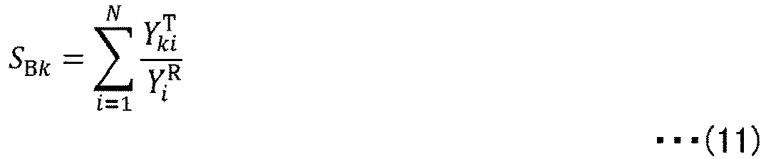
- Then, the first fitting step is executed again using the normalized Sci. In other words, the first fitting step and the second fitting step are executed a plurality of times repetitively until the error between Yi obs and Yicalc converges. The equation (8) expresses a value of Sci in a case where it is assumed that a sum of the first term and the second term on the right-hand side of the equation (6) is equal to the observed pattern Yi obs. As a result, the value of the temporary pattern Yi TMP is absorbed by the second term related to the residual group. Thus, at the end of calculation, the value of the temporary pattern Yi TMP converges to zero, or a value extremely close to zero.
- After Sck T and ScR are determined as described above, values of Sk and SR are calculated using those values. For example, when Yki T and Yi R are standardized in advance, Sk is equal to Sck T, and SR is equal to ScR. Then, those values are substituted into the equation (3) to calculate the weight fraction wk. Further, the value of the weight fraction wk is substituted into the equation (5) to calculate the weight fraction wR related to the residual group.
- Now, a method of calculating aR_av will be described.
- In a case where it is known at what mixture ratios components of what chemical compositions exist with respect to the residual group, aR_av can be determined directly from those items of information.
- In other words, when the residual group consists of a substance A (WA g) and a substance B (WB g), the residual group gives a scattering intensity expressed by the following equation (12) .

- When this scattering intensity is divided by a gross weight of the residual group, a scattering intensity per unit weight, that is, aR_av, is determined. In other words, aR_av is given by the following equation (13).

- When the equation (13) is generalized to the residual group consisting of K-T components, aR_av is expressed using the weight fraction wk as in the following equation (14).

- In the equation (14), ak' can be calculated based on the chemical composition information using the equation (2). Accordingly, in the case where it is known at what mixture ratios components of what chemical compositions exist in the residual group, aR_av can be calculated based on the equation (14).
- Next, description will be given of a case where, although the chemical composition information of the entire mixture (batch composition) is known, the chemical composition information is unknown for the residual group. The chemical composition information of the batch composition can be determined by applying fluorescent analysis to the batch composition, for example. Alternatively, when it can be assumed that there is no volatile component, chemical composition information of a raw material used for synthesis of the mixture can be directly used.
- In such case, the chemical composition information of the batch composition is substituted into the equation (2) to calculate ak for the entire mixture sample. This value is denoted by aB.
- As in the equation (14), aB of the batch composition is expressed by the following equation (15).

- The equation (15) is modified, and aR_av for the residual group is expressed by the following equation (16).

- In the equation (16), aB and ak' are known, but weight fractions wR and wk' are unknown. Thus, for example, assuming an initial value of aR_av to be aB, the weight fractions wR and wk' are calculated based on the equations (3) and (5), and are substituted again into the equation (16) to calculate aR_av again. This calculation can be repeated to calculate aR_av that is close to a true value.
-
FIG. 2 andFIG. 3 are flow charts illustrating operation of theanalysis device 14. - The
analysis device 14 first acquires the observed pattern Yi obs from the X-ray diffractometer 12 (Step S101). Further, a target pattern Yki T is read from the storage unit 16 (Step S102) . Thereafter, SA and SBk are calculated based on the equations (10) and (11) (Step S103). Further, the initial pattern Yi R is read from the storage unit 16 (Step S104). - Thereafter, every value of a correction pattern Sci is initialized to 1 (Step S105), and the first fitting step described above is executed (Step S106) . In other words, SCk T, ScR, and Yi TMP serving as fitting parameters are determined so that the error between Yi calc expressed in the equation (6) and the observed pattern Yi obs is minimized. In Step S106, Yicalc expressed in the equation (6) is acquired, and the values obtained in Step S102, Step S104, and Step S105 are substituted thereinto.
- Next, the correction pattern Sci (before normalization) is calculated based on the equation (8) (Step S107), and is normalized based on the equation (9) (Step S108).
- The processing of Step S105 to Step S108 described above is repeated until the error between Yicalc and the observed pattern Yi obs satisfies a convergence condition (Step S109).
- Thereafter, the
analysis device 14 reads the chemical composition information of the target components from thestorage unit 16, and calculates ak based on the equation (2) (Step S110) . Further, theanalysis device 14 calculates aR_av for the residual group (Step S111). For example, in the case where it is known at what mixture ratios components of what chemical compositions exist in the residual group, aR_av is calculated based on the equation (14). - Thereafter, the weight fraction wk of the target components is calculated based on the equation (3) (Step S112). Further, the weight fraction wR of the residual group is calculated based on the equation (5) (Step S113). Then, the weight fractions wk and wR are displayed on the display unit 18 (Step S114) .
-
FIG. 4 is a flow chart illustrating a procedure of calculating a variable aR_av. The processing illustrated inFIG. 4 is an example of the processing of Step S111 illustrated inFIG. 3 . Theanalysis device 14 reads the chemical composition information of the batch composition from thestorage unit 16, and calculates aB for the batch composition based on the equation (2) (Step S201) . Next, aB -1 is set as an initial value of aR_av -1 (Step S202), and the weight fractions wk and wR are calculated based on the equation (3) and the equation (5) (Step S203). Those values are substituted into the equation (16) to calculate aR_av -1 (Step S204) . The processing of Step S203 and Step S204 is repeated until aR_av -1 satisfies a convergence condition, and when the convergence condition is satisfied, aR_av -1 is output (Step S206) . This value may be used in the processing of Step S112. -
FIG. 5 andFIG. 6 are graphs showing examples of analysis of X-ray diffraction patterns of a mixture sample by theanalysis system 10 in the at least one embodiment of the present invention. The sample is a mixture containing α-quartz, albite, and kaolinite at mixture ratios of 1:1:1. A target component is α-quartz. A residual group is a mixture of albite and kaolinite. A diffraction pattern of the residual group per se is unknown. - In
FIG. 5 , a weight fraction of the target pattern is calculated using a known diffraction pattern of albite alone as Yi R of the equation (6). InFIG. 5 , thereference symbol 5A denotes the observed pattern Yi obs and the fitting pattern Yicalc in a superimposed manner. Thereference symbol 5B denotes an error between the observed pattern Yi obs and the fitting pattern Yi calc. The observed pattern Yi obs and the fitting pattern Yicalc completely fit to each other, and hence the error traces a straight line. Thereference symbol 5C denotes the correction pattern Sci for the error. The pattern denoted by thereference symbol 5C closely matches a known diffraction pattern of kaolinite alone (not shown). When a weight fraction of α-quartz was calculated under the above-mentioned conditions, a relative error with respect to a true value was about 0.17%. - Meanwhile, in
FIG. 6 , a weight fraction of the target pattern is calculated using a known diffraction pattern of glass-SiO2 alone as Yi R of the equation (6). InFIG. 6 , thereference symbol 6A denotes the observed pattern Yi obs and the fitting pattern Yicalc in a superimposed manner. Thereference symbol 6B denotes an error between the observed pattern Yi obs and the fitting pattern Yi calc. The observed pattern Yi obs and the fitting pattern Yicalc completely fit to each other, and hence the error also traces a straight line in this case. Thereference symbol 6C denotes the correction pattern Sci. The pattern denoted by thereference symbol 6C also resembles a pattern obtained by synthesizing the known diffraction pattern of albite alone and the known diffraction pattern of kaolinite alone (not shown) . When the weight fraction of α-quartz was calculated, the relative error with respect to the true value was similarly about 0.70%. - According to the at least one embodiment of the present invention described above, even in the case where diffraction patterns are known for only some components, intensity ratios can be calculated not only for the components for which the diffraction patterns are known, but also for the residual group for which diffraction patterns are unknown, and weight fractions of those components can be calculated accurately.
- In the above description, the intensity ratios are calculated by the present method to perform quantitative phase analysis, but the intensity ratios may be used for other purposes than quantitative phase analysis. For example, in a case where the residual group contains only one component, the component forming the residual group can be identified based on the unknown pattern Sci×Yi R after the calculation has converged.
- While there have been described what are at present considered to be certain embodiments of the invention, it will be understood that various modifications may be made thereto, and it is intended that the appended claims cover all such modifications as fall within the true spirit and scope of the invention.
Claims (6)
- A method of analyzing a diffraction pattern of a mixture, the method comprising:an observed pattern acquisition step (S101) of acquiring an observed pattern of X-ray diffraction;a fitting pattern acquisition step (S102-S105) of acquiring a fitting pattern including a term obtained by multiplying a known target pattern indicating a target component by a first intensity ratio, and a term obtained by multiplying an unknown pattern indicating a residual group consisting of one or more residual components by a second intensity ratio, and having the first intensity ratio, the second intensity ratio, and the unknown pattern as fitting parameters;a first fitting step (S106) of fitting the fitting pattern to the observed pattern by changing the first intensity ratio and the second intensity ratio in a state where the unknown pattern is set to an initial pattern; anda second fitting step (S107 and S108) of fitting, after the first fitting step (S106), the fitting pattern to the observed pattern by changing the unknown pattern while restricting the changes of the first intensity ratio and the second intensity ratio.
- The method of analyzing a diffraction pattern of a mixture according to claim 1, further comprising repeating the first fitting step and the second fitting step a plurality of times (S109).
- The method of analyzing a diffraction pattern of a mixture according to claim 1 or 2,wherein the fitting pattern further includes a term of a temporary pattern serving as a fitting parameter,wherein the first fitting step includes fitting the fitting pattern to the observed pattern by changing the temporary pattern as well as the first intensity ratio and the second intensity ratio, andwherein the second fitting step (S107 and S108) includes changing the unknown pattern so that at least a part of the term of the temporary pattern is absorbed by the term related to the residual group.
- The method of analyzing a diffraction pattern of a mixture according to any one of claims 1 to 3, further comprising performing quantitative phase analysis of the target component based on the first intensity ratio and the second intensity ratio (S110-S114) .
- A device for analyzing a diffraction pattern of a mixture, the device comprising:an observed pattern storage (16) configured to store data of an observed pattern of X-ray diffraction;a fitting pattern storage (16) configured to store data indicating a fitting pattern including a term obtained by multiplying a known target pattern indicating a target component by a first intensity ratio, and a term obtained by multiplying an unknown pattern indicating a residual group consisting of one or more residual components by a second intensity ratio, and having the first intensity ratio, the second intensity ratio, and the unknown pattern as fitting parameters;a first fitting module (14) configured to fit the fitting pattern to the observed pattern by changing the first intensity ratio and the second intensity ratio in a state where the unknown pattern is set to an initial pattern; anda second fitting module (14) configured to fit, after the fitting by the first fitting module, the fitting pattern to the observed pattern by changing the unknown pattern while restricting the changes of the first intensity ratio and the second intensity ratio.
- A computer-readable information storage medium having stored thereon a program for causing a computer to function as:an observed pattern storage (16) configured to store data of an observed pattern of X-ray diffraction;a fitting pattern storage (16) configured to store data indicating a fitting pattern including a term obtained by multiplying a known target pattern indicating a target component by a first intensity ratio, and a term obtained by multiplying an unknown pattern indicating a residual group consisting of one or more residual components by a second intensity ratio, and having the first intensity ratio, the second intensity ratio, and the unknown pattern as fitting parameters;a first fitting module (14) configured to fit the fitting pattern to the observed pattern by changing the first intensity ratio and the second intensity ratio in a state where the unknown pattern is set to an initial pattern; anda second fitting module (14) configured to fit, after the fitting by the first fitting module, the fitting pattern to the observed pattern by changing the unknown pattern while restricting the changes of the first intensity ratio and the second intensity ratio.
Applications Claiming Priority (1)
| Application Number | Priority Date | Filing Date | Title |
|---|---|---|---|
| JP2020206310A JP7414280B2 (en) | 2020-12-11 | 2020-12-11 | Mixture diffraction pattern analysis method, device, program and information storage medium |
Publications (2)
| Publication Number | Publication Date |
|---|---|
| EP4012391A1 true EP4012391A1 (en) | 2022-06-15 |
| EP4012391B1 EP4012391B1 (en) | 2024-10-16 |
Family
ID=78598884
Family Applications (1)
| Application Number | Title | Priority Date | Filing Date |
|---|---|---|---|
| EP21207661.6A Active EP4012391B1 (en) | 2020-12-11 | 2021-11-11 | Method and device for analyzing the diffraction pattern of a mixture, and information storage medium therefor |
Country Status (4)
| Country | Link |
|---|---|
| US (1) | US12031927B2 (en) |
| EP (1) | EP4012391B1 (en) |
| JP (1) | JP7414280B2 (en) |
| CN (1) | CN114689627B (en) |
Families Citing this family (2)
| Publication number | Priority date | Publication date | Assignee | Title |
|---|---|---|---|---|
| JP7833174B2 (en) * | 2022-03-02 | 2026-03-19 | 株式会社リガク | Diffraction pattern analyzer for mixtures, method, program, and information storage medium |
| JP7837555B2 (en) * | 2022-10-13 | 2026-03-31 | 株式会社リガク | Processing apparatus, system, method, and program |
Citations (3)
| Publication number | Priority date | Publication date | Assignee | Title |
|---|---|---|---|---|
| EP3425379A1 (en) * | 2016-02-29 | 2019-01-09 | Rigaku Corporation | Crystal phase quantitative analysis device, crystal phase quantitative analysis method, and crystal phase quantitative analysis program |
| JP2019184254A (en) | 2018-04-02 | 2019-10-24 | 株式会社リガク | Quantitative analyzer of amorphous phase, quantitative analysis method of amorphous phase, and quantitative analysis program of amorphous phase |
| EP3667304A1 (en) * | 2017-08-09 | 2020-06-17 | Rigaku Corporation | Crystal-phase quantitative analysis device, crystal-phase quantitative analysis method, and crystal-phase quantitative analysis program |
Family Cites Families (16)
| Publication number | Priority date | Publication date | Assignee | Title |
|---|---|---|---|---|
| JP2001083107A (en) | 1999-09-14 | 2001-03-30 | Asahi Kasei Corp | Material property analyzer for membrane |
| US7469036B2 (en) * | 2002-04-19 | 2008-12-23 | Los Alamos National Security, Llc | Analysis of macromolecules, ligands and macromolecule-ligand complexes |
| US7372941B2 (en) * | 2002-08-06 | 2008-05-13 | Ssci, Inc. | System and method for matching diffraction patterns |
| US7700915B2 (en) * | 2006-11-28 | 2010-04-20 | Canatu Oy | Method, computer program and apparatus for the characterization of molecules |
| KR100782712B1 (en) * | 2006-12-19 | 2007-12-05 | 주식회사 포스코 | Method of predicting component ratio of unknown mixture |
| JP2010249784A (en) | 2009-04-20 | 2010-11-04 | Rigaku Corp | X-ray diffraction analysis system and x-ray diffraction analysis method |
| JP2014140632A (en) * | 2012-12-27 | 2014-08-07 | Canon Inc | Computation apparatus, image acquisition method, program, and x-ray imaging system |
| JP6013950B2 (en) * | 2013-03-14 | 2016-10-25 | 株式会社リガク | Crystal phase identification method, crystal phase identification apparatus, and crystal phase identification program |
| US9372163B2 (en) * | 2014-01-28 | 2016-06-21 | Bruker Axs, Inc. | Method of conducting an X-ray diffraction-based crystallography analysis |
| GB201402318D0 (en) * | 2014-02-11 | 2014-03-26 | Oxford Instr Nanotechnology Tools Ltd | Method for materials analysis |
| US9494536B1 (en) * | 2015-06-01 | 2016-11-15 | Chevron U.S.A. Inc. | Methods for predicting corrosion rate of crude oil derived samples using X-ray absorption spectroscopy |
| WO2017063839A1 (en) * | 2015-10-12 | 2017-04-20 | Asml Netherlands B.V. | Methods and apparatus for simulating interaction of radiation with structures, metrology methods and apparatus, device manufacturing method |
| CN108770365B (en) * | 2016-02-17 | 2021-04-16 | 株式会社理学 | Analysis device, analysis method, and recording medium |
| JP6497784B2 (en) * | 2016-05-24 | 2019-04-10 | 株式会社リガク | Crystal phase identification method, crystal phase identification apparatus, and X-ray diffraction measurement system |
| JP6269886B1 (en) * | 2017-06-02 | 2018-01-31 | 株式会社フィゾニット | Calculation method of best solution, calculation method of dominant solution for powder diffraction pattern, and program thereof |
| EP3428629B1 (en) * | 2017-07-14 | 2022-12-07 | Malvern Panalytical B.V. | Analysis of x-ray spectra using curve fitting |
-
2020
- 2020-12-11 JP JP2020206310A patent/JP7414280B2/en active Active
-
2021
- 2021-11-11 EP EP21207661.6A patent/EP4012391B1/en active Active
- 2021-11-16 CN CN202111353444.XA patent/CN114689627B/en active Active
- 2021-12-09 US US17/546,656 patent/US12031927B2/en active Active
Patent Citations (4)
| Publication number | Priority date | Publication date | Assignee | Title |
|---|---|---|---|---|
| EP3425379A1 (en) * | 2016-02-29 | 2019-01-09 | Rigaku Corporation | Crystal phase quantitative analysis device, crystal phase quantitative analysis method, and crystal phase quantitative analysis program |
| EP3667304A1 (en) * | 2017-08-09 | 2020-06-17 | Rigaku Corporation | Crystal-phase quantitative analysis device, crystal-phase quantitative analysis method, and crystal-phase quantitative analysis program |
| JP2019184254A (en) | 2018-04-02 | 2019-10-24 | 株式会社リガク | Quantitative analyzer of amorphous phase, quantitative analysis method of amorphous phase, and quantitative analysis program of amorphous phase |
| EP3779418A1 (en) * | 2018-04-02 | 2021-02-17 | Rigaku Corporation | Amorphous phase quantitative analysis apparatus, amorphous phase quantitative analysis method, and amorphous phase quantitative analysis program |
Also Published As
| Publication number | Publication date |
|---|---|
| US20220187225A1 (en) | 2022-06-16 |
| US12031927B2 (en) | 2024-07-09 |
| JP7414280B2 (en) | 2024-01-16 |
| JP2022093174A (en) | 2022-06-23 |
| CN114689627B (en) | 2025-09-12 |
| CN114689627A (en) | 2022-07-01 |
| EP4012391B1 (en) | 2024-10-16 |
Similar Documents
| Publication | Publication Date | Title |
|---|---|---|
| DAVIS | RED SYSTEM OF THE CN MOLECULE. | |
| Zhang et al. | Iso-Compass: New freeware software for isotopic data reduction of LA-MC-ICP-MS | |
| JP6614740B2 (en) | X-ray fluorescence analysis method, X-ray fluorescence analysis program, and fluorescence X-ray analyzer | |
| Pereira et al. | Oxygen lines in solar granulation-II. Centre-to-limb variation, NLTE line formation, blends, and the solar oxygen abundance | |
| EP4012391B1 (en) | Method and device for analyzing the diffraction pattern of a mixture, and information storage medium therefor | |
| CN101473197B (en) | Method for making a multidimensional calibration model | |
| EP2859313B1 (en) | System and method for determining the presence of spectral components in the spectra of mixture | |
| WO2006014123A1 (en) | Method for producing independent multidimensional calibrating patterns | |
| John | Optimizing sample and spike concentrations for isotopic analysis by double-spike ICPMS | |
| Harutyunyan et al. | 3D non-LTE corrections for Li abundance and 6Li/7Li isotopic ratio in solar-type stars: I. Application to HD 207129 and HD 95456 | |
| US12287300B2 (en) | Device and method for analyzing diffraction pattern of mixture, and information storage medium | |
| CN112041670B (en) | Quantitative analysis device, analysis method and analysis procedure for amorphous phase | |
| Guarneri et al. | Fundamental physics with ESPRESSO: a new determination of the D/H ratio towards PKS1937-101 | |
| Dickinson et al. | Measuring 13C‐enriched CO2 in air with a cavity ring‐down spectroscopy gas analyser: Evaluation and calibration | |
| Šarčević et al. | Joint modelling of astrophysical systematics for cosmology with LSST cosmic shear | |
| Teixeira et al. | New Teff and [Fe/H] spectroscopic calibration for FGK dwarfs and GK giants | |
| JP7382508B2 (en) | A method for calibrating at least one mass spectrometer | |
| Schoeller | A review of the statistical considerations involved in the treatment of isotope dilution calibration data | |
| Pavlinskii et al. | Determination of low atomic number elements by X-ray fluorescence fundamental parameter method | |
| Webb | SIXPACK: A graphical user interface for XAS analysis | |
| US20250137921A1 (en) | Per-frequency correction of spectroscopic interference | |
| Gutierrez et al. | An elementary method to generate asymmetric profiles and some applications in X-ray diffraction analysis | |
| JPH11271244A (en) | Quantitative analysis method by X-ray spectrum | |
| Ampere | defined by fixed numerical values of seven defin-ing constants (Table 17.2) providing a fundamen | |
| Short | The ChromaStar+ modelling suite and the VALD line list |
Legal Events
| Date | Code | Title | Description |
|---|---|---|---|
| PUAI | Public reference made under article 153(3) epc to a published international application that has entered the european phase |
Free format text: ORIGINAL CODE: 0009012 |
|
| STAA | Information on the status of an ep patent application or granted ep patent |
Free format text: STATUS: THE APPLICATION HAS BEEN PUBLISHED |
|
| AK | Designated contracting states |
Kind code of ref document: A1 Designated state(s): AL AT BE BG CH CY CZ DE DK EE ES FI FR GB GR HR HU IE IS IT LI LT LU LV MC MK MT NL NO PL PT RO RS SE SI SK SM TR |
|
| STAA | Information on the status of an ep patent application or granted ep patent |
Free format text: STATUS: REQUEST FOR EXAMINATION WAS MADE |
|
| 17P | Request for examination filed |
Effective date: 20220930 |
|
| RBV | Designated contracting states (corrected) |
Designated state(s): AL AT BE BG CH CY CZ DE DK EE ES FI FR GB GR HR HU IE IS IT LI LT LU LV MC MK MT NL NO PL PT RO RS SE SI SK SM TR |
|
| GRAP | Despatch of communication of intention to grant a patent |
Free format text: ORIGINAL CODE: EPIDOSNIGR1 |
|
| STAA | Information on the status of an ep patent application or granted ep patent |
Free format text: STATUS: GRANT OF PATENT IS INTENDED |
|
| INTG | Intention to grant announced |
Effective date: 20240612 |
|
| GRAS | Grant fee paid |
Free format text: ORIGINAL CODE: EPIDOSNIGR3 |
|
| GRAA | (expected) grant |
Free format text: ORIGINAL CODE: 0009210 |
|
| STAA | Information on the status of an ep patent application or granted ep patent |
Free format text: STATUS: THE PATENT HAS BEEN GRANTED |
|
| AK | Designated contracting states |
Kind code of ref document: B1 Designated state(s): AL AT BE BG CH CY CZ DE DK EE ES FI FR GB GR HR HU IE IS IT LI LT LU LV MC MK MT NL NO PL PT RO RS SE SI SK SM TR |
|
| REG | Reference to a national code |
Ref country code: GB Ref legal event code: FG4D |
|
| REG | Reference to a national code |
Ref country code: NL Ref legal event code: FP |
|
| REG | Reference to a national code |
Ref country code: CH Ref legal event code: EP |
|
| REG | Reference to a national code |
Ref country code: IE Ref legal event code: FG4D |
|
| REG | Reference to a national code |
Ref country code: DE Ref legal event code: R096 Ref document number: 602021020288 Country of ref document: DE |
|
| REG | Reference to a national code |
Ref country code: LT Ref legal event code: MG9D |
|
| REG | Reference to a national code |
Ref country code: AT Ref legal event code: MK05 Ref document number: 1733295 Country of ref document: AT Kind code of ref document: T Effective date: 20241016 |
|
| PG25 | Lapsed in a contracting state [announced via postgrant information from national office to epo] |
Ref country code: PT Free format text: LAPSE BECAUSE OF FAILURE TO SUBMIT A TRANSLATION OF THE DESCRIPTION OR TO PAY THE FEE WITHIN THE PRESCRIBED TIME-LIMIT Effective date: 20250217 Ref country code: IS Free format text: LAPSE BECAUSE OF FAILURE TO SUBMIT A TRANSLATION OF THE DESCRIPTION OR TO PAY THE FEE WITHIN THE PRESCRIBED TIME-LIMIT Effective date: 20250216 Ref country code: HR Free format text: LAPSE BECAUSE OF FAILURE TO SUBMIT A TRANSLATION OF THE DESCRIPTION OR TO PAY THE FEE WITHIN THE PRESCRIBED TIME-LIMIT Effective date: 20241016 |
|
| PG25 | Lapsed in a contracting state [announced via postgrant information from national office to epo] |
Ref country code: FI Free format text: LAPSE BECAUSE OF FAILURE TO SUBMIT A TRANSLATION OF THE DESCRIPTION OR TO PAY THE FEE WITHIN THE PRESCRIBED TIME-LIMIT Effective date: 20241016 |
|
| PG25 | Lapsed in a contracting state [announced via postgrant information from national office to epo] |
Ref country code: BG Free format text: LAPSE BECAUSE OF FAILURE TO SUBMIT A TRANSLATION OF THE DESCRIPTION OR TO PAY THE FEE WITHIN THE PRESCRIBED TIME-LIMIT Effective date: 20241016 |
|
| PG25 | Lapsed in a contracting state [announced via postgrant information from national office to epo] |
Ref country code: ES Free format text: LAPSE BECAUSE OF FAILURE TO SUBMIT A TRANSLATION OF THE DESCRIPTION OR TO PAY THE FEE WITHIN THE PRESCRIBED TIME-LIMIT Effective date: 20241016 |
|
| PG25 | Lapsed in a contracting state [announced via postgrant information from national office to epo] |
Ref country code: NO Free format text: LAPSE BECAUSE OF FAILURE TO SUBMIT A TRANSLATION OF THE DESCRIPTION OR TO PAY THE FEE WITHIN THE PRESCRIBED TIME-LIMIT Effective date: 20250116 |
|
| PG25 | Lapsed in a contracting state [announced via postgrant information from national office to epo] |
Ref country code: GR Free format text: LAPSE BECAUSE OF FAILURE TO SUBMIT A TRANSLATION OF THE DESCRIPTION OR TO PAY THE FEE WITHIN THE PRESCRIBED TIME-LIMIT Effective date: 20250117 Ref country code: LV Free format text: LAPSE BECAUSE OF FAILURE TO SUBMIT A TRANSLATION OF THE DESCRIPTION OR TO PAY THE FEE WITHIN THE PRESCRIBED TIME-LIMIT Effective date: 20241016 Ref country code: AT Free format text: LAPSE BECAUSE OF FAILURE TO SUBMIT A TRANSLATION OF THE DESCRIPTION OR TO PAY THE FEE WITHIN THE PRESCRIBED TIME-LIMIT Effective date: 20241016 |
|
| PG25 | Lapsed in a contracting state [announced via postgrant information from national office to epo] |
Ref country code: PL Free format text: LAPSE BECAUSE OF FAILURE TO SUBMIT A TRANSLATION OF THE DESCRIPTION OR TO PAY THE FEE WITHIN THE PRESCRIBED TIME-LIMIT Effective date: 20241016 |
|
| PG25 | Lapsed in a contracting state [announced via postgrant information from national office to epo] |
Ref country code: RS Free format text: LAPSE BECAUSE OF FAILURE TO SUBMIT A TRANSLATION OF THE DESCRIPTION OR TO PAY THE FEE WITHIN THE PRESCRIBED TIME-LIMIT Effective date: 20250116 |
|
| PG25 | Lapsed in a contracting state [announced via postgrant information from national office to epo] |
Ref country code: SM Free format text: LAPSE BECAUSE OF FAILURE TO SUBMIT A TRANSLATION OF THE DESCRIPTION OR TO PAY THE FEE WITHIN THE PRESCRIBED TIME-LIMIT Effective date: 20241016 |
|
| PG25 | Lapsed in a contracting state [announced via postgrant information from national office to epo] |
Ref country code: MC Free format text: LAPSE BECAUSE OF FAILURE TO SUBMIT A TRANSLATION OF THE DESCRIPTION OR TO PAY THE FEE WITHIN THE PRESCRIBED TIME-LIMIT Effective date: 20241016 |
|
| PG25 | Lapsed in a contracting state [announced via postgrant information from national office to epo] |
Ref country code: DK Free format text: LAPSE BECAUSE OF FAILURE TO SUBMIT A TRANSLATION OF THE DESCRIPTION OR TO PAY THE FEE WITHIN THE PRESCRIBED TIME-LIMIT Effective date: 20241016 |
|
| PG25 | Lapsed in a contracting state [announced via postgrant information from national office to epo] |
Ref country code: LU Free format text: LAPSE BECAUSE OF NON-PAYMENT OF DUE FEES Effective date: 20241111 |
|
| REG | Reference to a national code |
Ref country code: DE Ref legal event code: R097 Ref document number: 602021020288 Country of ref document: DE |
|
| PG25 | Lapsed in a contracting state [announced via postgrant information from national office to epo] |
Ref country code: EE Free format text: LAPSE BECAUSE OF FAILURE TO SUBMIT A TRANSLATION OF THE DESCRIPTION OR TO PAY THE FEE WITHIN THE PRESCRIBED TIME-LIMIT Effective date: 20241016 |
|
| PG25 | Lapsed in a contracting state [announced via postgrant information from national office to epo] |
Ref country code: RO Free format text: LAPSE BECAUSE OF FAILURE TO SUBMIT A TRANSLATION OF THE DESCRIPTION OR TO PAY THE FEE WITHIN THE PRESCRIBED TIME-LIMIT Effective date: 20241016 |
|
| PG25 | Lapsed in a contracting state [announced via postgrant information from national office to epo] |
Ref country code: SK Free format text: LAPSE BECAUSE OF FAILURE TO SUBMIT A TRANSLATION OF THE DESCRIPTION OR TO PAY THE FEE WITHIN THE PRESCRIBED TIME-LIMIT Effective date: 20241016 |
|
| PG25 | Lapsed in a contracting state [announced via postgrant information from national office to epo] |
Ref country code: CZ Free format text: LAPSE BECAUSE OF FAILURE TO SUBMIT A TRANSLATION OF THE DESCRIPTION OR TO PAY THE FEE WITHIN THE PRESCRIBED TIME-LIMIT Effective date: 20241016 |
|
| PG25 | Lapsed in a contracting state [announced via postgrant information from national office to epo] |
Ref country code: IT Free format text: LAPSE BECAUSE OF FAILURE TO SUBMIT A TRANSLATION OF THE DESCRIPTION OR TO PAY THE FEE WITHIN THE PRESCRIBED TIME-LIMIT Effective date: 20241016 |
|
| PLBE | No opposition filed within time limit |
Free format text: ORIGINAL CODE: 0009261 |
|
| STAA | Information on the status of an ep patent application or granted ep patent |
Free format text: STATUS: NO OPPOSITION FILED WITHIN TIME LIMIT |
|
| REG | Reference to a national code |
Ref country code: BE Ref legal event code: MM Effective date: 20241130 |
|
| PG25 | Lapsed in a contracting state [announced via postgrant information from national office to epo] |
Ref country code: SE Free format text: LAPSE BECAUSE OF FAILURE TO SUBMIT A TRANSLATION OF THE DESCRIPTION OR TO PAY THE FEE WITHIN THE PRESCRIBED TIME-LIMIT Effective date: 20241016 |
|
| 26N | No opposition filed |
Effective date: 20250717 |
|
| PG25 | Lapsed in a contracting state [announced via postgrant information from national office to epo] |
Ref country code: BE Free format text: LAPSE BECAUSE OF NON-PAYMENT OF DUE FEES Effective date: 20241130 |
|
| PG25 | Lapsed in a contracting state [announced via postgrant information from national office to epo] |
Ref country code: IE Free format text: LAPSE BECAUSE OF NON-PAYMENT OF DUE FEES Effective date: 20241111 |
|
| REG | Reference to a national code |
Ref country code: CH Ref legal event code: U11 Free format text: ST27 STATUS EVENT CODE: U-0-0-U10-U11 (AS PROVIDED BY THE NATIONAL OFFICE) Effective date: 20251201 |
|
| PGFP | Annual fee paid to national office [announced via postgrant information from national office to epo] |
Ref country code: NL Payment date: 20251119 Year of fee payment: 5 |
|
| PGFP | Annual fee paid to national office [announced via postgrant information from national office to epo] |
Ref country code: DE Payment date: 20251119 Year of fee payment: 5 |
|
| PGFP | Annual fee paid to national office [announced via postgrant information from national office to epo] |
Ref country code: GB Payment date: 20251121 Year of fee payment: 5 |
|
| PGFP | Annual fee paid to national office [announced via postgrant information from national office to epo] |
Ref country code: FR Payment date: 20251126 Year of fee payment: 5 |
|
| PGFP | Annual fee paid to national office [announced via postgrant information from national office to epo] |
Ref country code: CH Payment date: 20251201 Year of fee payment: 5 |
|
| PG25 | Lapsed in a contracting state [announced via postgrant information from national office to epo] |
Ref country code: HU Free format text: LAPSE BECAUSE OF FAILURE TO SUBMIT A TRANSLATION OF THE DESCRIPTION OR TO PAY THE FEE WITHIN THE PRESCRIBED TIME-LIMIT; INVALID AB INITIO Effective date: 20211111 |
|
| PG25 | Lapsed in a contracting state [announced via postgrant information from national office to epo] |
Ref country code: CY Free format text: LAPSE BECAUSE OF FAILURE TO SUBMIT A TRANSLATION OF THE DESCRIPTION OR TO PAY THE FEE WITHIN THE PRESCRIBED TIME-LIMIT; INVALID AB INITIO Effective date: 20211111 |