EP4012361A2 - Optical forms for multi-channel double-pass dispersive spectrometers - Google Patents
Optical forms for multi-channel double-pass dispersive spectrometers Download PDFInfo
- Publication number
- EP4012361A2 EP4012361A2 EP21208888.4A EP21208888A EP4012361A2 EP 4012361 A2 EP4012361 A2 EP 4012361A2 EP 21208888 A EP21208888 A EP 21208888A EP 4012361 A2 EP4012361 A2 EP 4012361A2
- Authority
- EP
- European Patent Office
- Prior art keywords
- pass
- double
- mirror
- spectrometer
- electromagnetic radiation
- Prior art date
- Legal status (The legal status is an assumption and is not a legal conclusion. Google has not performed a legal analysis and makes no representation as to the accuracy of the status listed.)
- Withdrawn
Links
Images


Classifications
-
- G—PHYSICS
- G01—MEASURING; TESTING
- G01J—MEASUREMENT OF INTENSITY, VELOCITY, SPECTRAL CONTENT, POLARISATION, PHASE OR PULSE CHARACTERISTICS OF INFRARED, VISIBLE OR ULTRAVIOLET LIGHT; COLORIMETRY; RADIATION PYROMETRY
- G01J3/00—Spectrometry; Spectrophotometry; Monochromators; Measuring colours
- G01J3/28—Investigating the spectrum
- G01J3/2823—Imaging spectrometer
-
- G—PHYSICS
- G01—MEASURING; TESTING
- G01J—MEASUREMENT OF INTENSITY, VELOCITY, SPECTRAL CONTENT, POLARISATION, PHASE OR PULSE CHARACTERISTICS OF INFRARED, VISIBLE OR ULTRAVIOLET LIGHT; COLORIMETRY; RADIATION PYROMETRY
- G01J3/00—Spectrometry; Spectrophotometry; Monochromators; Measuring colours
- G01J3/02—Details
- G01J3/0205—Optical elements not provided otherwise, e.g. optical manifolds, diffusers, windows
- G01J3/0208—Optical elements not provided otherwise, e.g. optical manifolds, diffusers, windows using focussing or collimating elements, e.g. lenses or mirrors; performing aberration correction
-
- G—PHYSICS
- G01—MEASURING; TESTING
- G01J—MEASUREMENT OF INTENSITY, VELOCITY, SPECTRAL CONTENT, POLARISATION, PHASE OR PULSE CHARACTERISTICS OF INFRARED, VISIBLE OR ULTRAVIOLET LIGHT; COLORIMETRY; RADIATION PYROMETRY
- G01J3/00—Spectrometry; Spectrophotometry; Monochromators; Measuring colours
- G01J3/02—Details
- G01J3/0286—Constructional arrangements for compensating for fluctuations caused by temperature, humidity or pressure, or using cooling or temperature stabilization of parts of the device; Controlling the atmosphere inside a spectrometer, e.g. vacuum
-
- G—PHYSICS
- G01—MEASURING; TESTING
- G01J—MEASUREMENT OF INTENSITY, VELOCITY, SPECTRAL CONTENT, POLARISATION, PHASE OR PULSE CHARACTERISTICS OF INFRARED, VISIBLE OR ULTRAVIOLET LIGHT; COLORIMETRY; RADIATION PYROMETRY
- G01J3/00—Spectrometry; Spectrophotometry; Monochromators; Measuring colours
- G01J3/02—Details
- G01J3/0294—Multi-channel spectroscopy
-
- G—PHYSICS
- G01—MEASURING; TESTING
- G01J—MEASUREMENT OF INTENSITY, VELOCITY, SPECTRAL CONTENT, POLARISATION, PHASE OR PULSE CHARACTERISTICS OF INFRARED, VISIBLE OR ULTRAVIOLET LIGHT; COLORIMETRY; RADIATION PYROMETRY
- G01J3/00—Spectrometry; Spectrophotometry; Monochromators; Measuring colours
- G01J3/12—Generating the spectrum; Monochromators
- G01J3/18—Generating the spectrum; Monochromators using diffraction elements, e.g. grating
Definitions
- an imaging spectrometer is composed of an objective or imaging optical module, which forms a scene image at a slit, and a spectral optical module, which receives and collimates the line field of view from the objective, disperses or separates the radiation as a function of wavelength, and images it onto a two dimensional detector array.
- a double pass technique is sometimes used in the spectral optics.
- U.S. Patent No. 5,260,767 discloses the use of the non-relayed reflective triplet optical form as a double-pass, single-channel dispersive spectrometer.
- 7,382,498 discloses the use of the non-relayed reflective triplet optical form as a double-pass, dual-channel dispersive spectrometer.
- the reflective triplet optical form is non-reimaging (non-relayed)
- the entire spectrometer optical train must be cooled, generally inside a cryo-vac housing. This requirement results in a cool-down time measuring several hours, which may severely limit the use of the instrument in certain applications or environments.
- aspects and embodiments are directed to the use of a reimaging or relayed all-reflective optical form, including a four-mirror anastigmat (4MA) or five-mirror anastigmat (5MA), in double-pass dispersive spectrometers.
- the relayed nature of the 4MA or 5MA allows for removal of the optics from the cooling chamber (e.g., cryo-vac housing), resulting in an ability to use a much smaller chamber that houses only the slit(s) and imaging detectors/sensors, such as a tactical-style Dewar, for example, and greatly reduced cool-down times. For example, cool-down times on the order of a few minutes may be achieved.
- the all-reflective 4MA or 5MA optical forms may preserve all the benefits of the conventional reflective triplet (such as little to no spectral limitations and multi-channel capability), while accommodating larger format imaging detectors and providing fast optical speeds, as discussed further below.
- a multi-channel double-pass imaging spectrometer comprises at least one slit through which incident electromagnetic radiation enters the spectrometer, at least one imaging detector positioned at an image plane of the spectrometer, the image plane being co-located with the at least one slit, double-pass all-reflective reimaging optics configured to receive the electromagnetic radiation from the at least one slit and to output a collimated beam of the electromagnetic radiation, and further configured to produce a reimaged pupil positioned between the double-pass all-reflective reimaging optics and the image plane, a beamsplitter configured to split the collimated beam of the electromagnetic radiation into a first spectral band and a second spectral band, a first dispersive element configured to spectrally disperse the first spectral band of the electromagnetic radiation to provide a first dispersed output, the first dispersive element being oriented to direct the first dispersed output through the double-pass all-reflective reimaging optics
- the multi-channel double-pass imaging spectrometer further comprises a cooling chamber positioned between the reimaged pupil and the at least one slit, the at least one imaging detector being located within the cooling chamber.
- the double-pass all-reflective reimaging optics includes a four-mirror anastigmat.
- the four-mirror anastigmat may include, for example, a primary mirror having a positive optical power, a secondary mirror, a tertiary mirror having a negative optical power, and a quaternary mirror having a positive optical power.
- the secondary mirror is non-powered.
- a sum of the optical powers of the primary, secondary, tertiary, and quaternary mirrors is zero.
- the double-pass all-reflective reimaging optics includes a five-mirror anastigmat.
- the five-mirror anastigmat may include, for example, a first mirror having a positive optical power, a second mirror having a negative optical power, a third mirror having a positive optical power, a fourth mirror having a negative optical power, and a fifth mirror having a positive optical power.
- a sum of the optical powers of the first, second, third, fourth, and fifth mirrors is zero.
- first and second dispersive elements are prisms. In another example the first and second dispersive elements are diffraction gratings.
- the at least one imaging detector may include a focal plane array sensor, for example.
- the double-pass all-reflective reimaging optics may further include a real entrance pupil, and be configured to output the collimated beam of the electromagnetic radiation at the real entrance pupil.
- the first and second dispersive elements are located proximate the real entrance pupil.
- a double-pass infrared imaging spectrometer comprises at least one slit through which incident infrared electromagnetic radiation enters the spectrometer, at least one imaging detector positioned at an image plane of the spectrometer, the image plane being co-located with the at least one slit, double-pass all-reflective reimaging optics configured to receive the infrared electromagnetic radiation from the at least one slit and to output a collimated beam of the infrared electromagnetic radiation at a real entrance pupil, and further configured to produce a reimaged pupil positioned between the double-pass all-reflective reimaging optics and the image plane, at least one dispersive element positioned proximate the real entrance pupil and configured to spectrally disperse the infrared electromagnetic radiation to provide a dispersed output, the dispersive element being oriented to direct the dispersed output through the double-pass all-reflective reimaging optics to the image plane, and a cooling chamber positioned
- the double-pass all-reflective reimaging optics includes a four-mirror anastigmat. In another example the double-pass all-reflective reimaging optics includes a five-mirror anastigmat.
- the double-pass infrared imaging spectrometer may be a dual-channel spectrometer, for example.
- the dual-channel double-pass infrared imaging spectrometer may further comprise a beamsplitter configured to separate the collimated beam of the infrared electromagnetic radiation into a first spectral band and a second spectral band.
- the at least one dispersive element may include a first dispersive element configured to spectrally disperse the first spectral band of the electromagnetic radiation to provide a first dispersed output, the first dispersive element being oriented to direct the first dispersed output through the double-pass all-reflective reimaging optics to the image plane, and a second dispersive element configured to spectrally disperse the second spectral band of the electromagnetic radiation to provide a second dispersed output, the second dispersive element being oriented to direct the second dispersed output through the double-pass all-reflective reimaging optics to the image plane.
- aspects and embodiments are directed to the use of relayed optical form, such as a four-mirror anastigmat (4MA) or five-mirror anastigmat (5MA) in double-pass, multi-channel, dispersive imaging spectrometers.
- the 4MA or 5MA optical forms disclosed and used herein are all-reflective and flat-field, and provide a real entrance pupil, as discussed further below.
- U.S. Patent 5,550,672 discloses examples of the structural and functional characteristics of the 4MA optical form in detail.
- U.S. Patent 6,902,282 discloses examples of the structural and functional characteristics of the 5MA optical form in detail.
- the relayed nature of the 4MA and 5MA optical forms provides the advantage of allowing for ambient optics for infrared applications; a significant benefit over conventional non-reimaging optical forms, such as the reflective triplet.
- the additional mirrors included in the 4MA and 5MA optical forms relative to the reflective triplet may accommodate larger format slit(s) and FPA(s) configurations and faster optical speeds.
- U.S. Patent No. 8,507,866 discloses an infrared spectrometer having ambient optics; however that configuration has spectral limitations and may not be suited to multi-channel operation. Additionally, the use of a "narcissus mirror" slit substrate, as disclosed in U.S. Patent No. 8,507,866 may pose difficulties for spectrometers with large formats. Embodiments of the spectrometers disclosed herein using the 4MA or 5MA optical forms may avoid such disadvantages and retain the benefits associated with the conventional reflective triplet optical form, while providing additional capability, as discussed in more detail below.
- references to "or” may be construed as inclusive so that any terms described using “or” may indicate any of a single, more than one, and all of the described terms. Any references to front and back, left and right, top and bottom, upper and lower, and vertical and horizontal are intended for convenience of description, not to limit the present systems and methods or their components to any one positional or spatial orientation.
- a multi-channel dispersive imaging spectrometer is implemented using an all-reflective 4MA optical form.
- FIGS. 1A and 1B there is illustrated an example of a dual-channel double-pass spectrometer using the all-reflective 4MA optical form.
- the spectrometer 100 is dual-channel in the tangential plane; however those skilled in the art will readily appreciate that the spectrometer could alternatively be dual-channel in the sagittal plane.
- Electromagnetic radiation from a viewed scene is input to the spectrometer, as indicated by arrow 105, via a slit 110.
- the spectrometer 100 is a dual-channel spectrometer, and accordingly, the electromagnetic radiation may be split into a first spectral band (channel) 120a and a second spectral band 120b.
- Two imaging sensors or detectors 130a and 130b, one for each spectral channel, may be located at a common image plane substantially co-located with the slit 110.
- the spectrometer optics includes a 4MA 170 comprised of a primary mirror 140, a secondary mirror 145, a tertiary mirror 150, and a quaternary mirror 155, arranged in a double-pass configuration and forming a reimaged pupil at 160.
- the spectrometer 100 further includes a real entrance pupil 165 at which a pair of reflective dispersive elements, one for each spectral channel, may be placed and which spectrally disperse the electromagnetic radiation and reflect the dispersed radiation back through the 4MA 170 to the imaging detectors 130a, 130b.
- FIGS. 1A and 1B illustrates an example of the spectrometer 100 showing first and second dispersive elements 210 and 215, respectively, along with a beamsplitter 220 configured to split the electromagnetic radiation into the two spectral bands 120a, 120b and direct each spectral band to the respective dispersive element.
- the dispersive elements 210, 215 may be diffraction gratings or prisms, for example.
- the electromagnetic radiation 120a, 120b enters the spectrometer system via the slit 110 and the mirrors of the 4MA 170 cooperate to collimate the incident radiation to the real entrance pupil 165 and dispersive elements 210 and 215, and back to the imaging detectors 130a, 103b adjacent to the slit 110.
- the 4MA 170 is thus termed double-pass because the electromagnetic radiation is collimated on the way to the dispersive elements 210, 215 and returns through the 4MA to be imaged on the common image plane where the imaging detectors 130a, 103b are located.
- the imaging detectors 130a, 130b are focal plane array (FPA) imaging sensors.
- the spectrometer 100 includes two imaging sensors 130a, 130b, one for each of the two spectral channels; however, in other examples, a single dual-band FPA or other imaging sensor may be used.
- the power distribution of the primary mirror 140, tertiary mirror 150, and quaternary mirror 155 is positive, negative, and positive, respectively.
- the secondary mirror 145 is preferably non-powered, but could have a slight positive or negative power, and it may have a higher-order aspheric figure.
- the precise powers of the mirrors 140, 145, 150, and 155 may be selected such that the sum of the powers is zero.
- a zero sum provides correction of the Petzval sum, causing a zero curvature in the focal plane (i.e., a substantially flat field condition).
- the cross-section of the primary mirror 140 may be conic (e.g., paraboloid, hyperboloid or ellipsoid) or a higher-order aspheric.
- the cross-section of the tertiary mirror 150 may be hyperboloid, but can also be a higher-order aspheric.
- the cross-section of the quaternary mirror 155 may be ellipsoid, but can also be a higher-order aspheric.
- the secondary mirror 145 though nominally flat, may generally be provided with an aspheric surface. The aspheric surface also allows the secondary mirror 145 to reduce aberrations in the pupil imagery.
- the geometries of the mirrors may be selected at the discretion of the optical designer. Composition of the mirrors 140, 145, 150, and 155 is dependent upon the application for which the spectrometer 100 is intended.
- the mirrors 140, 145, 150, and 155 can be made of materials such as glass, plastic, metal, or advanced composite materials.
- the method of fabricating the mirrors 140, 145, 150, and 155 may be dependent upon the composition. Fabrication processes may include conventional polishing, computer-controlled polishing, precision machining, replication, and molding, for example.
- the 4MA 170 provides compact, reimaging, all-reflective optics configured to image a wide field of view onto a flat field, thus being well suited for multi-channel spectrometer applications.
- the relayed nature of the 4MA 170, with its associated reimaged pupil 160 allows for location of the slit(s) 110 and the imaging sensors 130a, 130b inside a cooling chamber, while the optical train can remain at ambient temperature.
- a relatively small cooling chamber 230 which houses the imaging detectors 130a, 130b may be positioned between the reimaged pupil 160 and the slit(s) 110.
- the chamber 230 may be a tactical Dewar or other type of cryo-vac chamber, for example.
- the chamber 230 may include a first window 245 and a second window 240 that are transparent to the electromagnetic radiation 120a, 120b to allow the electromagnetic radiation to enter and leave the chamber.
- the first window 245 may be positioned prior to but substantially close to the slit(s) 110, and the second window 240 may be positioned after but substantially close to the reimaged pupil 160.
- the mirrors 140, 145, 150, and 155, along with the dispersive elements 210, 215 and the beamsplitter 220 are located outside of the cooling chamber 230 and are therefore at ambient temperature.
- the electromagnetic radiation from the slit(s) 110 to the dispersive elements 210, 215 and back to the imaging detectors 130a, 130b may be entirely confined to the ambient low emissivity mirror surfaces of the 4MA, and thus the imaging detectors 130a, 130b "see" a minimum of thermally emitted background radiation.
- FIG. 3 illustrates an example of a conventional dual-channel imaging spectrometer 300 including two imaging detectors 310a, 310b and based on the reflective triplet optical form.
- incident electromagnetic radiation enters the spectrometer via an entrance pupil 320, is collimated by a conventional three-mirror reflective triplet comprised of mirrors 330, 335, 340 on its way to dispersive elements 350, 355, and returns via the reflective triplet to be imaged on a common image plane at which the imaging detectors 310a, 310b are located.
- a beamsplitter 360 is used to the split the electromagnetic radiation into two spectral channels.
- the reflective triplet (comprised of mirrors 330, 335, 340) of the conventional spectrometer 300 is non-reimaged and does not produce an intermediate image plane or reimaged pupil.
- the entire optical train must be cooled within a large cooling chamber 370, as illustrated in FIG. 3 .
- the cooling chamber 370 includes an optically transparent window 375 positioned prior to but substantially close to the entrance pupil 320. Comparison between FIGS.
- the cooling time for the spectrometer 100 may be on the order of minutes, rather than hours as is typically the case for the conventional spectrometer 300.
- a multi-channel dispersive imaging spectrometer may be implemented using an all-reflective 5MA optical form in a double-pass configuration.
- FIGS. 4A and 4B illustrate an example of a dual-channel double-pass spectrometer 400 using the 5MA optical form.
- the spectrometer 400 is dual-channel in the sagittal plane and includes a pair of slits 110a 110b; however those skilled in the art will readily appreciate that the spectrometer could alternatively be dual-channel in the tangential plane.
- Electromagnetic radiation from a viewed scene is input to the spectrometer 400, as indicated by arrow 105, via the slit(s) 110.
- the spectrometer 400 is a dual-channel spectrometer, and accordingly, the electromagnetic radiation may be split into a first spectral band (channel) 120a and a second spectral band 120b using a beamsplitter 220, as discussed above and as illustrated in FIG. 5 , for example.
- Two imaging detectors 130a and 130b, one for each spectral channel, may be located at image planes substantially co-located with the slits 110a, 110b.
- the spectrometer optics includes a 5MA 410 comprised of a first mirror 420, a second mirror 425, a third mirror 430, a fourth mirror 435, and a fifth mirror 440 arranged in a double-pass configuration and having an entrance pupil at 165 and a reimaged pupil 160.
- the first mirror 420 reflects the electromagnetic radiation to and from a real entrance pupil 165. In one example, the first mirror 420 has positive optical power.
- the second mirror 425 reflects the electromagnetic radiation to and from the first mirror 420. In one example, the second mirror 425 has negative optical power.
- the third mirror 430 reflects the electromagnetic radiation to and from the second mirror 425. In one example, the third mirror 430 has positive optical power.
- the fourth mirror 435 reflects the electromagnetic radiation to and from the third mirror 430. In one example, the fourth mirror 435 has negative optical power.
- the fifth mirror 440 reflects the electromagnetic radiation to and from the fourth mirror 435. In one example, the fifth mirror 440 has positive optical power.
- the fifth mirror 440 further receives the electromagnetic radiation from the slit(s) 110 and, on the return path, reflects the electromagnetic radiation toward the imaging detectors 130a and 130b. Desirably, the sum of the optical powers of all of the mirrors 420, 425, 430, 435, and 440 is substantially zero. This satisfies the Petzval sum criterion of substantially zero to form a flat image at the image plane(s) at which the imaging detectors 130a, 130b are located.
- the spectrometer 400 further includes a pair of reflective dispersive elements, one for each spectral channel, located at or near the real entrance pupil 165 and which spectrally disperse the electromagnetic radiation and reflect the dispersed radiation back through the 5MA 410 to the imaging detectors 130a, 130b.
- FIG. 5 illustrates an example of the spectrometer 400 showing first and second dispersive elements 210 and 215, respectively, and a beamsplitter 220 configured to split the electromagnetic radiation into the two spectral bands 120a, 120b and direct each spectral band to the respective dispersive element.
- the 5MA 410 provides all-reflective reimaging optics configured to image a wide field of view onto a flat field, and, like the 4MA 170, is well suited for multi-channel spectrometer applications.
- the relayed nature of the 5MA , 410 allows for location of the slit(s) 110 and the imaging sensors 130a, 130b inside a cooling chamber, while the optical train can remain at ambient temperature.
- a relatively small cooling chamber 510 which houses the imaging detectors 130a, 130b may be positioned between the reimaged pupil 160 and the slit(s) 110.
- the chamber 510 may be a tactical Dewar or other type of cryo-vac chamber, for example.
- the 5MA 410, along with the dispersive elements 210, 215 and the beamsplitter 220 are located outside of the cooling chamber 510 and are therefore at ambient temperature.
- the electromagnetic radiation from the slit(s) 110 to the dispersive elements 210, 215 and back to the imaging detectors 130a, 130b may be entirely confined to the ambient low emissivity mirror surfaces of the 5MA, and thus the imaging detectors 130a, 130b "see" a minimum of thermally emitted background radiation. Comparison between FIGS.
- the cooling time for the spectrometer 400 may be on the order of minutes, rather than hours as is typically the case for the conventional spectrometer 300.
- the five mirrors of the 5MA 410 provide additional design choices and degrees of freedom relative to the 4MA 170, and even more so relative to the conventional three-mirror reflective triplet. Accordingly, the 5MA 410 may provide enhanced capability to correct for aberrations and/or distortion, and use of the 5MA 410 for the spectrometer 400 allows for the spectrometer 400 to accommodate larger slit(s) and FPA(s) formats and faster optical speeds. Additionally, use of the all-reflective 5MA 410 preserves all the capabilities of the conventional reflective triplet configuration (e.g., no spectral limitations and multi-channel operation), while allowing the spectrometer optics to be placed outside of the cooling chamber, as discussed above.
- Table 1 below provides two design examples of spectrometer configurations using examples of the 5MA 410.
- Example 1 corresponds to an optical speed of F/2.5
- example 2 corresponds to an optical speed of F/2.0.
- the dimensional extent of the 5MA 410 (measured from the upper tip of the first mirror 420 to the lower tip of the fifth mirror 440 in FIG. 4B is approximately 71 cm.
- Example 2 Aperture (grating) 10.3 cm 12.8 cm Optical Speed F/2.5 F/2.0 Focal Length 25.75 cm 25.52 cm Format 3.7 cm ⁇ 8.37 cm 3.7 cm ⁇ 8.37 cm Field of view (FOV) 8.2 ⁇ 18.5 degrees 8.2 ⁇ 18.5 degrees Cavity Pupil 6.2 cm 7.9 cm Pupil Magnification 1.66X 1.62X Cavity Length 15.6 cm 15.7 cm Diffraction limited at 2.26 ⁇ m 2.85 ⁇ m Distortion Average 4 ⁇ m 7 ⁇ m Pupil Error Average 0.4 mm 0.5 mm
- aspects and embodiments provide optical forms for a multi-channel double-pass imaging spectrometer that may enable design and implementation of a compact, high performance spectrometer with numerous advantages.
- the use of the 4MA or 5MA reimaging optical form allows the spectrometer optics to be maintained at ambient temperature while a relatively small cooling chamber that houses only the imaging sensors, and optionally the slit(s) and/or some small components associated with the imaging sensors (e.g., a filter), can be used to provide the desired cooling. This dramatically reduces the cooling time and energy while maintaining high performance for infrared imaging applications.
- the all-reflective 4MA or 5MA optical forms have little to no spectral limitations (unlike optical forms that include refractive elements, which are highly spectrally dependent/variable) and are easily compatible with multi-channel applications.
- spectrometers based on the 4MA or 5MA optical forms, as disclosed herein, may provide numerous advantages and improvements over conventional imaging spectrometers based on the reflective triplet, or other non-reimaging and/or refractive optical forms.
Landscapes
- Physics & Mathematics (AREA)
- Spectroscopy & Molecular Physics (AREA)
- General Physics & Mathematics (AREA)
- Spectrometry And Color Measurement (AREA)
- Lenses (AREA)
Abstract
Description
- Typically, an imaging spectrometer is composed of an objective or imaging optical module, which forms a scene image at a slit, and a spectral optical module, which receives and collimates the line field of view from the objective, disperses or separates the radiation as a function of wavelength, and images it onto a two dimensional detector array. A double pass technique is sometimes used in the spectral optics. For example,
U.S. Patent No. 5,260,767 discloses the use of the non-relayed reflective triplet optical form as a double-pass, single-channel dispersive spectrometer. For another example,U.S. Patent No. 7,382,498 discloses the use of the non-relayed reflective triplet optical form as a double-pass, dual-channel dispersive spectrometer. As the reflective triplet optical form is non-reimaging (non-relayed), when used for infrared applications, the entire spectrometer optical train must be cooled, generally inside a cryo-vac housing. This requirement results in a cool-down time measuring several hours, which may severely limit the use of the instrument in certain applications or environments. - Aspects and embodiments are directed to the use of a reimaging or relayed all-reflective optical form, including a four-mirror anastigmat (4MA) or five-mirror anastigmat (5MA), in double-pass dispersive spectrometers. For infrared applications, the relayed nature of the 4MA or 5MA allows for removal of the optics from the cooling chamber (e.g., cryo-vac housing), resulting in an ability to use a much smaller chamber that houses only the slit(s) and imaging detectors/sensors, such as a tactical-style Dewar, for example, and greatly reduced cool-down times. For example, cool-down times on the order of a few minutes may be achieved. Additionally, the all-reflective 4MA or 5MA optical forms may preserve all the benefits of the conventional reflective triplet (such as little to no spectral limitations and multi-channel capability), while accommodating larger format imaging detectors and providing fast optical speeds, as discussed further below.
- According to one embodiment, a multi-channel double-pass imaging spectrometer comprises at least one slit through which incident electromagnetic radiation enters the spectrometer, at least one imaging detector positioned at an image plane of the spectrometer, the image plane being co-located with the at least one slit, double-pass all-reflective reimaging optics configured to receive the electromagnetic radiation from the at least one slit and to output a collimated beam of the electromagnetic radiation, and further configured to produce a reimaged pupil positioned between the double-pass all-reflective reimaging optics and the image plane, a beamsplitter configured to split the collimated beam of the electromagnetic radiation into a first spectral band and a second spectral band, a first dispersive element configured to spectrally disperse the first spectral band of the electromagnetic radiation to provide a first dispersed output, the first dispersive element being oriented to direct the first dispersed output through the double-pass all-reflective reimaging optics to the image plane, and a second dispersive element configured to spectrally disperse the second spectral band of the electromagnetic radiation to provide a second dispersed output, the second dispersive element being oriented to direct the second dispersed output through the double-pass all-reflective reimaging optics to the image plane.
- In one example the multi-channel double-pass imaging spectrometer further comprises a cooling chamber positioned between the reimaged pupil and the at least one slit, the at least one imaging detector being located within the cooling chamber.
- In one example the double-pass all-reflective reimaging optics includes a four-mirror anastigmat. The four-mirror anastigmat may include, for example, a primary mirror having a positive optical power, a secondary mirror, a tertiary mirror having a negative optical power, and a quaternary mirror having a positive optical power. In one example the secondary mirror is non-powered. In another example a sum of the optical powers of the primary, secondary, tertiary, and quaternary mirrors is zero.
- In another example the double-pass all-reflective reimaging optics includes a five-mirror anastigmat. The five-mirror anastigmat may include, for example, a first mirror having a positive optical power, a second mirror having a negative optical power, a third mirror having a positive optical power, a fourth mirror having a negative optical power, and a fifth mirror having a positive optical power. In one example a sum of the optical powers of the first, second, third, fourth, and fifth mirrors is zero.
- In one example the first and second dispersive elements are prisms. In another example the first and second dispersive elements are diffraction gratings.
- The at least one imaging detector may include a focal plane array sensor, for example.
- The double-pass all-reflective reimaging optics may further include a real entrance pupil, and be configured to output the collimated beam of the electromagnetic radiation at the real entrance pupil. In one example the first and second dispersive elements are located proximate the real entrance pupil.
- According to another embodiment, a double-pass infrared imaging spectrometer comprises at least one slit through which incident infrared electromagnetic radiation enters the spectrometer, at least one imaging detector positioned at an image plane of the spectrometer, the image plane being co-located with the at least one slit, double-pass all-reflective reimaging optics configured to receive the infrared electromagnetic radiation from the at least one slit and to output a collimated beam of the infrared electromagnetic radiation at a real entrance pupil, and further configured to produce a reimaged pupil positioned between the double-pass all-reflective reimaging optics and the image plane, at least one dispersive element positioned proximate the real entrance pupil and configured to spectrally disperse the infrared electromagnetic radiation to provide a dispersed output, the dispersive element being oriented to direct the dispersed output through the double-pass all-reflective reimaging optics to the image plane, and a cooling chamber positioned between the reimaged pupil and the at least one slit, the at least one imaging detector being positioned within the cooling chamber, and the double-pass all-reflective reimaging optics being positioned outside the cooling chamber.
- In one example the double-pass all-reflective reimaging optics includes a four-mirror anastigmat. In another example the double-pass all-reflective reimaging optics includes a five-mirror anastigmat.
- The double-pass infrared imaging spectrometer may be a dual-channel spectrometer, for example. In one such example, the dual-channel double-pass infrared imaging spectrometer may further comprise a beamsplitter configured to separate the collimated beam of the infrared electromagnetic radiation into a first spectral band and a second spectral band. The at least one dispersive element may include a first dispersive element configured to spectrally disperse the first spectral band of the electromagnetic radiation to provide a first dispersed output, the first dispersive element being oriented to direct the first dispersed output through the double-pass all-reflective reimaging optics to the image plane, and a second dispersive element configured to spectrally disperse the second spectral band of the electromagnetic radiation to provide a second dispersed output, the second dispersive element being oriented to direct the second dispersed output through the double-pass all-reflective reimaging optics to the image plane.
- Still other aspects, embodiments, and advantages of these exemplary aspects and embodiments are discussed in detail below. Embodiments disclosed herein may be combined with other embodiments in any manner consistent with at least one of the principles disclosed herein, and references to "an embodiment," "some embodiments," "an alternate embodiment," "various embodiments," "one embodiment" or the like are not necessarily mutually exclusive and are intended to indicate that a particular feature, structure, or characteristic described may be included in at least one embodiment. The appearances of such terms herein are not necessarily all referring to the same embodiment.
- Various aspects of at least one embodiment are discussed below with reference to the accompanying figures, which are not intended to be drawn to scale. The figures are included to provide illustration and a further understanding of the various aspects and embodiments, and are incorporated in and constitute a part of this specification, but are not intended as a definition of the limits of the invention. In the figures, each identical or nearly identical component that is illustrated in various figures is represented by a like numeral. For purposes of clarity, not every component may be labeled in every figure. In the figures:
-
FIG. 1A is a ray trace section of one example of a dual-channel double-pass spectrometer in the tangential plane using the four-mirror anastigmat optical form according to aspects of the present invention; -
FIG. 1B is a plan view of the ray trace ofFIG. 1A ; -
FIG. 2 is a ray trace section of one of example of the spectrometer ofFIGS. 1A and1B according to aspects of the present invention; -
FIG. 3 is a ray trace section of a conventional dual-channel spectrometer using a reflective triplet optical form; -
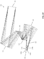
FIG. 4A is a plan view of a ray trace section of one example of a dual-channel double pass spectrometer in the sagittal plane using the five mirror anastigmat optical form according to aspects of the present invention; -
FIG. 4B is a tangential plane view of the ray trace section ofFIG. 4A ; and -
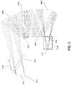
FIG. 5 is a ray trace section of one of example of the spectrometer ofFIGS. 4A and4B according to aspects of the present invention. - Aspects and embodiments are directed to the use of relayed optical form, such as a four-mirror anastigmat (4MA) or five-mirror anastigmat (5MA) in double-pass, multi-channel, dispersive imaging spectrometers. The 4MA or 5MA optical forms disclosed and used herein are all-reflective and flat-field, and provide a real entrance pupil, as discussed further below.
U.S. Patent 5,550,672 discloses examples of the structural and functional characteristics of the 4MA optical form in detail. Similarly,U.S. Patent 6,902,282 discloses examples of the structural and functional characteristics of the 5MA optical form in detail. The relayed nature of the 4MA and 5MA optical forms provides the advantage of allowing for ambient optics for infrared applications; a significant benefit over conventional non-reimaging optical forms, such as the reflective triplet. In addition, as discussed further below, the additional mirrors included in the 4MA and 5MA optical forms relative to the reflective triplet may accommodate larger format slit(s) and FPA(s) configurations and faster optical speeds. -
U.S. Patent No. 8,507,866 discloses an infrared spectrometer having ambient optics; however that configuration has spectral limitations and may not be suited to multi-channel operation. Additionally, the use of a "narcissus mirror" slit substrate, as disclosed inU.S. Patent No. 8,507,866 may pose difficulties for spectrometers with large formats. Embodiments of the spectrometers disclosed herein using the 4MA or 5MA optical forms may avoid such disadvantages and retain the benefits associated with the conventional reflective triplet optical form, while providing additional capability, as discussed in more detail below. - It is to be appreciated that embodiments of the methods and apparatuses discussed herein are not limited in application to the details of construction and the arrangement of components set forth in the following description or illustrated in the accompanying drawings. The methods and apparatuses are capable of implementation in other embodiments and of being practiced or of being carried out in various ways. Examples of specific implementations are provided herein for illustrative purposes only and are not intended to be limiting. Also, the phraseology and terminology used herein is for the purpose of description and should not be regarded as limiting. The use herein of "including," "comprising," "having," "containing," "involving," and variations thereof is meant to encompass the items listed thereafter and equivalents thereof as well as additional items. References to "or" may be construed as inclusive so that any terms described using "or" may indicate any of a single, more than one, and all of the described terms. Any references to front and back, left and right, top and bottom, upper and lower, and vertical and horizontal are intended for convenience of description, not to limit the present systems and methods or their components to any one positional or spatial orientation.
- As discussed above, according to one embodiment, a multi-channel dispersive imaging spectrometer is implemented using an all-reflective 4MA optical form. Referring to
FIGS. 1A and1B , there is illustrated an example of a dual-channel double-pass spectrometer using the all-reflective 4MA optical form. In the illustrated example, thespectrometer 100 is dual-channel in the tangential plane; however those skilled in the art will readily appreciate that the spectrometer could alternatively be dual-channel in the sagittal plane. Electromagnetic radiation from a viewed scene is input to the spectrometer, as indicated byarrow 105, via aslit 110. In the illustrated example, thespectrometer 100 is a dual-channel spectrometer, and accordingly, the electromagnetic radiation may be split into a first spectral band (channel) 120a and a secondspectral band 120b. Two imaging sensors ordetectors slit 110. - In the illustrated example, the spectrometer optics includes a
4MA 170 comprised of aprimary mirror 140, asecondary mirror 145, atertiary mirror 150, and aquaternary mirror 155, arranged in a double-pass configuration and forming a reimaged pupil at 160. Thespectrometer 100 further includes areal entrance pupil 165 at which a pair of reflective dispersive elements, one for each spectral channel, may be placed and which spectrally disperse the electromagnetic radiation and reflect the dispersed radiation back through the4MA 170 to theimaging detectors FIG. 2 illustrates an example of thespectrometer 100 showing first and seconddispersive elements beamsplitter 220 configured to split the electromagnetic radiation into the twospectral bands dispersive elements FIGS. 1A and1B , theelectromagnetic radiation slit 110 and the mirrors of the4MA 170 cooperate to collimate the incident radiation to thereal entrance pupil 165 anddispersive elements imaging detectors 130a, 103b adjacent to theslit 110. The4MA 170 is thus termed double-pass because the electromagnetic radiation is collimated on the way to thedispersive elements imaging detectors 130a, 103b are located. - In one example the
imaging detectors spectrometer 100 includes twoimaging sensors - According to one embodiment, the power distribution of the
primary mirror 140,tertiary mirror 150, andquaternary mirror 155 is positive, negative, and positive, respectively. Thesecondary mirror 145 is preferably non-powered, but could have a slight positive or negative power, and it may have a higher-order aspheric figure. The precise powers of themirrors primary mirror 140 may be conic (e.g., paraboloid, hyperboloid or ellipsoid) or a higher-order aspheric. The cross-section of thetertiary mirror 150 may be hyperboloid, but can also be a higher-order aspheric. The cross-section of thequaternary mirror 155 may be ellipsoid, but can also be a higher-order aspheric. Thesecondary mirror 145, though nominally flat, may generally be provided with an aspheric surface. The aspheric surface also allows thesecondary mirror 145 to reduce aberrations in the pupil imagery. The geometries of the mirrors may be selected at the discretion of the optical designer. Composition of themirrors spectrometer 100 is intended. For example, for infrared applications, themirrors mirrors - The
4MA 170 provides compact, reimaging, all-reflective optics configured to image a wide field of view onto a flat field, thus being well suited for multi-channel spectrometer applications. In addition, the relayed nature of the4MA 170, with its associatedreimaged pupil 160, allows for location of the slit(s) 110 and theimaging sensors FIG. 2 , a relatively small cooling chamber 230 (or cavity) which houses theimaging detectors reimaged pupil 160 and the slit(s) 110. Thechamber 230 may be a tactical Dewar or other type of cryo-vac chamber, for example. Thechamber 230 may include afirst window 245 and asecond window 240 that are transparent to theelectromagnetic radiation first window 245 may be positioned prior to but substantially close to the slit(s) 110, and thesecond window 240 may be positioned after but substantially close to thereimaged pupil 160. Themirrors dispersive elements beamsplitter 220 are located outside of thecooling chamber 230 and are therefore at ambient temperature. The electromagnetic radiation from the slit(s) 110 to thedispersive elements imaging detectors imaging detectors -
FIG. 3 illustrates an example of a conventional dual-channel imaging spectrometer 300 including twoimaging detectors entrance pupil 320, is collimated by a conventional three-mirror reflective triplet comprised ofmirrors dispersive elements imaging detectors beamsplitter 360 is used to the split the electromagnetic radiation into two spectral channels. In contrast to embodiments of thespectrometer 100 based on the4MA 170 discussed above, the reflective triplet (comprised ofmirrors conventional spectrometer 300 is non-reimaged and does not produce an intermediate image plane or reimaged pupil. As a result, for infrared applications, the entire optical train must be cooled within alarge cooling chamber 370, as illustrated inFIG. 3 . The coolingchamber 370 includes an opticallytransparent window 375 positioned prior to but substantially close to theentrance pupil 320. Comparison betweenFIGS. 2 and3 illustrates one advantage of thespectrometer 100 based on the 4MA optical form, namely the ability to use a far smaller cooling chamber 230 (compared to the chamber 370) with most of the optical components being at ambient temperature. As a result, the cooling time for thespectrometer 100 may be on the order of minutes, rather than hours as is typically the case for theconventional spectrometer 300. - According to another embodiment, a multi-channel dispersive imaging spectrometer may be implemented using an all-reflective 5MA optical form in a double-pass configuration.
FIGS. 4A and4B illustrate an example of a dual-channel double-pass spectrometer 400 using the 5MA optical form. In the illustrated example, thespectrometer 400 is dual-channel in the sagittal plane and includes a pair ofslits 110a 110b; however those skilled in the art will readily appreciate that the spectrometer could alternatively be dual-channel in the tangential plane. Electromagnetic radiation from a viewed scene is input to thespectrometer 400, as indicated byarrow 105, via the slit(s) 110. In the illustrated example, thespectrometer 400 is a dual-channel spectrometer, and accordingly, the electromagnetic radiation may be split into a first spectral band (channel) 120a and a secondspectral band 120b using abeamsplitter 220, as discussed above and as illustrated inFIG. 5 , for example. Twoimaging detectors slits - In the illustrated example, the spectrometer optics includes a
5MA 410 comprised of afirst mirror 420, asecond mirror 425, athird mirror 430, afourth mirror 435, and afifth mirror 440 arranged in a double-pass configuration and having an entrance pupil at 165 and areimaged pupil 160. Thefirst mirror 420 reflects the electromagnetic radiation to and from areal entrance pupil 165. In one example, thefirst mirror 420 has positive optical power. Thesecond mirror 425 reflects the electromagnetic radiation to and from thefirst mirror 420. In one example, thesecond mirror 425 has negative optical power. Thethird mirror 430 reflects the electromagnetic radiation to and from thesecond mirror 425. In one example, thethird mirror 430 has positive optical power. Thefourth mirror 435 reflects the electromagnetic radiation to and from thethird mirror 430. In one example, thefourth mirror 435 has negative optical power. Thefifth mirror 440 reflects the electromagnetic radiation to and from thefourth mirror 435. In one example, thefifth mirror 440 has positive optical power. Thefifth mirror 440 further receives the electromagnetic radiation from the slit(s) 110 and, on the return path, reflects the electromagnetic radiation toward theimaging detectors mirrors imaging detectors - The
spectrometer 400 further includes a pair of reflective dispersive elements, one for each spectral channel, located at or near thereal entrance pupil 165 and which spectrally disperse the electromagnetic radiation and reflect the dispersed radiation back through the5MA 410 to theimaging detectors FIG. 5 illustrates an example of thespectrometer 400 showing first and seconddispersive elements beamsplitter 220 configured to split the electromagnetic radiation into the twospectral bands - Thus, the
5MA 410 provides all-reflective reimaging optics configured to image a wide field of view onto a flat field, and, like the4MA 170, is well suited for multi-channel spectrometer applications. In addition, similar to the4MA 170, the relayed nature of the 5MA , 410 allows for location of the slit(s) 110 and theimaging sensors FIG. 5 , a relativelysmall cooling chamber 510 which houses theimaging detectors reimaged pupil 160 and the slit(s) 110. Thechamber 510 may be a tactical Dewar or other type of cryo-vac chamber, for example. The5MA 410, along with thedispersive elements beamsplitter 220 are located outside of thecooling chamber 510 and are therefore at ambient temperature. The electromagnetic radiation from the slit(s) 110 to thedispersive elements imaging detectors imaging detectors FIGS. 5 and3 illustrates one advantage of thespectrometer 400 based on the 5MA optical form, namely the ability to use a far smaller cooling chamber 510 (compared to the chamber 370) with most of the optical components being at ambient temperature. As a result, the cooling time for thespectrometer 400 may be on the order of minutes, rather than hours as is typically the case for theconventional spectrometer 300. - In addition, the five mirrors of the
5MA 410 provide additional design choices and degrees of freedom relative to the4MA 170, and even more so relative to the conventional three-mirror reflective triplet. Accordingly, the5MA 410 may provide enhanced capability to correct for aberrations and/or distortion, and use of the5MA 410 for thespectrometer 400 allows for thespectrometer 400 to accommodate larger slit(s) and FPA(s) formats and faster optical speeds. Additionally, use of the all-reflective 5MA 410 preserves all the capabilities of the conventional reflective triplet configuration (e.g., no spectral limitations and multi-channel operation), while allowing the spectrometer optics to be placed outside of the cooling chamber, as discussed above. - Table 1 below provides two design examples of spectrometer configurations using examples of the
5MA 410. Example 1 corresponds to an optical speed of F/2.5, and example 2 corresponds to an optical speed of F/2.0. In each case, the dimensional extent of the 5MA 410 (measured from the upper tip of thefirst mirror 420 to the lower tip of thefifth mirror 440 inFIG. 4B is approximately 71 cm.TABLE 1 Characteristic Example 1 Example 2 Aperture (grating) 10.3 cm 12.8 cm Optical Speed F/2.5 F/2.0 Focal Length 25.75 cm 25.52 cm Format 3.7 cm × 8.37 cm 3.7 cm × 8.37 cm Field of view (FOV) 8.2 × 18.5 degrees 8.2 × 18.5 degrees Cavity Pupil 6.2 cm 7.9 cm Pupil Magnification 1.66X 1.62X Cavity Length 15.6 cm 15.7 cm Diffraction limited at 2.26 µm 2.85 µm Distortion Average 4 µm 7 µm Pupil Error Average 0.4 mm 0.5 mm - Thus, aspects and embodiments provide optical forms for a multi-channel double-pass imaging spectrometer that may enable design and implementation of a compact, high performance spectrometer with numerous advantages. As discussed above, for infrared applications in which cooling of the imaging sensors is highly desirable and typically necessary to achieve acceptable performance, the use of the 4MA or 5MA reimaging optical form allows the spectrometer optics to be maintained at ambient temperature while a relatively small cooling chamber that houses only the imaging sensors, and optionally the slit(s) and/or some small components associated with the imaging sensors (e.g., a filter), can be used to provide the desired cooling. This dramatically reduces the cooling time and energy while maintaining high performance for infrared imaging applications. In addition, the all-reflective 4MA or 5MA optical forms have little to no spectral limitations (unlike optical forms that include refractive elements, which are highly spectrally dependent/variable) and are easily compatible with multi-channel applications. Thus, spectrometers based on the 4MA or 5MA optical forms, as disclosed herein, may provide numerous advantages and improvements over conventional imaging spectrometers based on the reflective triplet, or other non-reimaging and/or refractive optical forms.
- Having described above several aspects of at least one embodiment, it is to be appreciated various alterations, modifications, and improvements will readily occur to those skilled in the art. Such alterations, modifications, and improvements are intended to be part of this disclosure and are intended to be within the scope of the invention. Accordingly, the foregoing description and drawings are by way of example only, and the scope of the invention should be determined from proper construction of the appended claims, and their equivalents.
- The following is a non-exhaustive list of embodiments that may or may not be claimed.
- 1. A multi-channel double-pass imaging spectrometer comprising:
- at least one slit through which incident electromagnetic radiation enters the spectrometer;
- at least one imaging detector positioned at an image plane of the spectrometer, the image plane being co-located with the at least one slit;
- double-pass all-reflective reimaging optics configured to receive the electromagnetic radiation from the at least one slit and to output a collimated beam of the electromagnetic radiation, and further configured to produce a reimaged pupil positioned between the double-pass all-reflective reimaging optics and the image plane;
- a beamsplitter configured to split the collimated beam of the electromagnetic radiation into a first spectral band and a second spectral band;
- a first dispersive element configured to spectrally disperse the first spectral band of the electromagnetic radiation to provide a first dispersed output, the first dispersive element being oriented to direct the first dispersed output through the double-pass all-reflective reimaging optics to the image plane; and
- a second dispersive element configured to spectrally disperse the second spectral band of the electromagnetic radiation to provide a second dispersed output, the second dispersive element being oriented to direct the second dispersed output through the double-pass all-reflective reimaging optics to the image plane.
- 2. The multi-channel double-pass imaging spectrometer of embodiment 1 further comprising a cooling chamber positioned between the reimaged pupil and the at least one slit, the at least one imaging detector being located within the cooling chamber.
- 3. The multi-channel double-pass imaging spectrometer of embodiment 1 wherein the double- pass all-reflective reimaging optics includes a four-mirror anastigmat.
- 4. The multi-channel double-pass imaging spectrometer of embodiment 3 wherein the four-mirror anastigmat includes:
- a primary mirror having a positive optical power;
- a secondary mirror;
- a tertiary mirror having a negative optical power; and
- a quaternary mirror having a positive optical power.
- 5. The multi-channel double-pass imaging spectrometer of embodiment 4 wherein the secondary mirror is non-powered.
- 6. The multi-channel double-pass imaging spectrometer of embodiment 5 wherein a sum of the optical powers of the primary, secondary, tertiary, and quaternary mirrors is zero.
- 7. The multi-channel double-pass imaging spectrometer of embodiment 1 wherein the double-pass all-reflective reimaging optics includes a five-mirror anastigmat.
- 8. The multi-channel double-pass imaging spectrometer of embodiment 7 wherein the five-mirror anastigmat includes:
- a first mirror having a positive optical power;
- a second mirror having a negative optical power;
- a third mirror having a positive optical power;
- a fourth mirror having a negative optical power; and
- a fifth mirror having a positive optical power.
- 9. The multi-channel double-pass imaging spectrometer of embodiment 8 wherein a sum of the optical powers of the first, second, third, fourth, and fifth mirrors is zero.
- 10. The multi-channel double-pass imaging spectrometer of embodiment 1 wherein the first and second dispersive elements are prisms.
- 11. The multi-channel double-pass imaging spectrometer of embodiment 1 wherein the first and second dispersive elements are diffraction gratings.
- 12. The multi-channel double-pass imaging spectrometer of embodiment 1 wherein the at least one imaging detector includes a focal plane array sensor.
- 13. The multi-channel double-pass imaging spectrometer of embodiment 1 wherein the double-pass all-reflective reimaging optics further include a real entrance pupil, and are configured to output the collimated beam of the electromagnetic radiation at the real entrance pupil.
- 14. The multi-channel double-pass imaging spectrometer of embodiment 13 wherein the first and second dispersive elements are located proximate the real entrance pupil.
- 15. A double-pass infrared imaging spectrometer comprising:
- at least one slit through which incident infrared electromagnetic radiation enters the spectrometer;
- at least one imaging detector positioned at an image plane of the spectrometer, the image plane being co-located with the at least one slit;
- double-pass all-reflective reimaging optics configured to receive the infrared electromagnetic radiation from the at least one slit and to output a collimated beam of the infrared electromagnetic radiation at a real entrance pupil, and further configured to produce a reimaged pupil positioned between the double-pass all-reflective reimaging optics and the image plane;
- at least one dispersive element positioned proximate the real entrance pupil and configured to spectrally disperse the infrared electromagnetic radiation to provide a dispersed output, the dispersive element being oriented to direct the dispersed output through the double-pass all-reflective reimaging optics to the image plane; and
- a cooling chamber positioned between the reimaged pupil and the at least one slit, the at least one imaging detector being positioned within the cooling chamber, and the double-pass all-reflective reimaging optics being positioned outside the cooling chamber.
- 16. The double-pass infrared imaging spectrometer of embodiment 15 wherein the double-pass all-reflective reimaging optics includes a four-mirror anastigmat.
- 17. The double-pass infrared imaging spectrometer of embodiment 15 wherein the double-pass all-reflective reimaging optics includes a five-mirror anastigmat.
- 18. The double-pass infrared imaging spectrometer of embodiment 15 wherein the spectrometer is a dual-channel spectrometer and further comprising a beamsplitter configured to separate the collimated beam of the infrared electromagnetic radiation into a first spectral band and a second spectral band; and
wherein the at least one dispersive element includes:- a first dispersive element configured to spectrally disperse the first spectral band of the electromagnetic radiation to provide a first dispersed output, the first dispersive element being oriented to direct the first dispersed output through the double-pass all-reflective reimaging optics to the image plane; and
- a second dispersive element configured to spectrally disperse the second spectral band of the electromagnetic radiation to provide a second dispersed output, the second dispersive element being oriented to direct the second dispersed output through the double-pass all-reflective reimaging optics to the image plane.
Claims (13)
- A double-pass infrared imaging spectrometer comprising:at least one slit through which incident infrared electromagnetic radiation enters the spectrometer;at least one imaging detector positioned at an image plane of the spectrometer, the image plane being co-located with the at least one slit;double-pass all-reflective reimaging optics configured to receive the infrared electromagnetic radiation from the at least one slit and to collimate the infrared electromagnetic radiation to a real entrance pupil, and further configured to produce a reimaged pupil positioned between the double-pass all-reflective reimaging optics and the image plane;at least one dispersive element positioned proximate the real entrance pupil and configured to spectrally disperse the infrared electromagnetic radiation to provide a dispersed output, the dispersive element being oriented to direct the dispersed output through the double-pass all-reflective reimaging optics to the image plane; anda cooling chamber positioned between the reimaged pupil and the at least one slit, the at least one imaging detector being positioned within the cooling chamber, and the double-pass all-reflective reimaging optics being positioned outside the cooling chamber.
- The double-pass infrared imaging spectrometer of claim 1 wherein the double-pass all-reflective reimaging optics includes a four-mirror anastigmat.
- The multi-channel double-pass imaging spectrometer of claim 2 wherein the four-mirror anastigmat includes:a primary mirror having a positive optical power;a secondary mirror;a tertiary mirror having a negative optical power; anda quaternary mirror having a positive optical power.
- The multi-channel double-pass imaging spectrometer of claim 3 wherein the secondary mirror is non-powered.
- The multi-channel double-pass imaging spectrometer of claim 4 wherein a sum of the optical powers of the primary, secondary, tertiary, and quaternary mirrors is zero.
- The double-pass infrared imaging spectrometer of claim 1 wherein the double-pass all-reflective reimaging optics includes a five-mirror anastigmat.
- The multi-channel double-pass imaging spectrometer of claim 6 wherein the five-mirror anastigmat includes:a first mirror having a positive optical power;a second mirror having a negative optical power;a third mirror having a positive optical power;a fourth mirror having a negative optical power; anda fifth mirror having a positive optical power.
- The multi-channel double-pass imaging spectrometer of claim 7 wherein a sum of the optical powers of the first, second, third, fourth, and fifth mirrors is zero.
- The multi-channel double-pass imaging spectrometer of claim 1 wherein the first and second dispersive elements are prisms.
- The multi-channel double-pass imaging spectrometer of claim 1 wherein the first and second dispersive elements are diffraction gratings.
- The multi-channel double-pass imaging spectrometer of claim 1 wherein the at least one imaging detector includes a focal plane array sensor.
- The multi-channel double-pass imaging spectrometer of claim 1 wherein the first and second dispersive elements are located proximate the real entrance pupil.
- The double-pass infrared imaging spectrometer of claim 1 wherein the spectrometer is a dual-channel spectrometer and further comprising a beamsplitter configured to separate the collimated infrared electromagnetic radiation into a first spectral band and a second spectral band; and
wherein the at least one dispersive element includes:a first dispersive element configured to spectrally disperse the first spectral band of the electromagnetic radiation to provide a first dispersed output, the first dispersive element being oriented to direct the first dispersed output through the double-pass all-reflective reimaging optics to the image plane; anda second dispersive element configured to spectrally disperse the second spectral band of the electromagnetic radiation to provide a second dispersed output, the second dispersive element being oriented to direct the second dispersed output through the double-pass all-reflective reimaging optics to the image plane.
Applications Claiming Priority (3)
| Application Number | Priority Date | Filing Date | Title |
|---|---|---|---|
| US14/689,229 US9354116B1 (en) | 2015-04-17 | 2015-04-17 | Optical forms for multi-channel double-pass dispersive spectrometers |
| PCT/US2016/015886 WO2016167856A1 (en) | 2015-04-17 | 2016-02-01 | Optical forms for multi-channel double-pass dispersive spectrometers |
| EP16705876.7A EP3283862A1 (en) | 2015-04-17 | 2016-02-01 | Optical forms for multi-channel double-pass dispersive spectrometers |
Related Parent Applications (1)
| Application Number | Title | Priority Date | Filing Date |
|---|---|---|---|
| EP16705876.7A Division EP3283862A1 (en) | 2015-04-17 | 2016-02-01 | Optical forms for multi-channel double-pass dispersive spectrometers |
Publications (2)
| Publication Number | Publication Date |
|---|---|
| EP4012361A2 true EP4012361A2 (en) | 2022-06-15 |
| EP4012361A3 EP4012361A3 (en) | 2022-08-17 |
Family
ID=55405465
Family Applications (2)
| Application Number | Title | Priority Date | Filing Date |
|---|---|---|---|
| EP16705876.7A Withdrawn EP3283862A1 (en) | 2015-04-17 | 2016-02-01 | Optical forms for multi-channel double-pass dispersive spectrometers |
| EP21208888.4A Withdrawn EP4012361A3 (en) | 2015-04-17 | 2016-02-01 | Optical forms for multi-channel double-pass dispersive spectrometers |
Family Applications Before (1)
| Application Number | Title | Priority Date | Filing Date |
|---|---|---|---|
| EP16705876.7A Withdrawn EP3283862A1 (en) | 2015-04-17 | 2016-02-01 | Optical forms for multi-channel double-pass dispersive spectrometers |
Country Status (5)
| Country | Link |
|---|---|
| US (1) | US9354116B1 (en) |
| EP (2) | EP3283862A1 (en) |
| IL (1) | IL253629B (en) |
| TW (1) | TWI685646B (en) |
| WO (1) | WO2016167856A1 (en) |
Families Citing this family (11)
| Publication number | Priority date | Publication date | Assignee | Title |
|---|---|---|---|---|
| FR3066618B1 (en) * | 2017-05-18 | 2019-06-28 | Thales | BIFOCAL ANASTIGMATE TELESCOPE WITH FIVE MIRRORS |
| US10185133B1 (en) | 2017-09-15 | 2019-01-22 | Raytheon Company | Reflective triplet foreoptics for multi-channel double-pass dispersive spectrometers |
| US10809124B2 (en) | 2018-05-07 | 2020-10-20 | Perkinelmer Health Sciences, Inc. | Spectrometers and instruments including them |
| US11287637B2 (en) | 2020-01-22 | 2022-03-29 | Raytheon Company | Multi-channel sensor using a rear-stopped reflective triplet |
| US11268860B2 (en) | 2020-07-24 | 2022-03-08 | Raytheon Company | Radiometric calibration of detector |
| KR20230136669A (en) * | 2021-02-10 | 2023-09-26 | 주식회사 씨에스오 | Small form factor multi-spectrum four-reflector-based imaging system |
| CN113804631A (en) * | 2021-08-23 | 2021-12-17 | 中国科学院国家空间科学中心 | Surveillance System for Spectral Information Acquisition |
| CN113899450B (en) * | 2021-09-24 | 2022-12-09 | 中国科学院西安光学精密机械研究所 | Medium wave infrared spectrometer capable of eliminating heat difference |
| DE102021211046A1 (en) * | 2021-09-30 | 2023-03-30 | Micro-Epsilon Optronic Gmbh | Spectrometer, distance measuring system and method for operating a spectrometer |
| CN117232652B (en) * | 2022-06-08 | 2026-04-14 | 中国科学院长春光学精密机械与物理研究所 | Ultraviolet double-channel common-path imaging spectrometer |
| CN116337227A (en) * | 2023-04-19 | 2023-06-27 | 苏州中科行智智能科技有限公司 | Small Color Distortion Slit Spectrometer |
Citations (5)
| Publication number | Priority date | Publication date | Assignee | Title |
|---|---|---|---|---|
| US5260767A (en) | 1991-12-16 | 1993-11-09 | Hughes Aircraft Company | Compact all-reflective imaging spectrometer |
| US5550672A (en) | 1994-05-23 | 1996-08-27 | Hughes Electronics | Off-axis three-mirror anastignat having corrector mirror |
| US6902282B2 (en) | 2002-03-22 | 2005-06-07 | Raytheon Company | Fast, wide-field-of-view, relayed multimirror optical system |
| US7382498B1 (en) | 2007-04-30 | 2008-06-03 | Raytheon Company | Two-channel imaging spectrometer utilizing shared objective, collimating, and imaging optics |
| US8507866B2 (en) | 2011-12-13 | 2013-08-13 | Raytheon Company | Cold-shielded infrared dispersive spectrometer with all ambient optics |
Family Cites Families (5)
| Publication number | Priority date | Publication date | Assignee | Title |
|---|---|---|---|---|
| US4733955A (en) | 1986-04-14 | 1988-03-29 | Hughes Aircraft Company | Reflective optical triplet having a real entrance pupil |
| ATE411543T1 (en) | 2004-12-15 | 2008-10-15 | Europ Agence Spatiale | WIDE-ANGLE FOUR-MIRROR TELESCOPE WITH ASPHERIC EXTERNAL-AXIS MIRRORS |
| FR2925173B1 (en) | 2007-12-18 | 2010-04-23 | Thales Sa | WIDE CATOPTRIC SYSTEM |
| US8436992B2 (en) * | 2011-07-27 | 2013-05-07 | Raytheon Company | Low distortion spectrometer |
| US9030660B2 (en) * | 2012-09-19 | 2015-05-12 | Raytheon Company | Multi-band imaging spectrometer |
-
2015
- 2015-04-17 US US14/689,229 patent/US9354116B1/en active Active
-
2016
- 2016-02-01 WO PCT/US2016/015886 patent/WO2016167856A1/en not_active Ceased
- 2016-02-01 EP EP16705876.7A patent/EP3283862A1/en not_active Withdrawn
- 2016-02-01 EP EP21208888.4A patent/EP4012361A3/en not_active Withdrawn
- 2016-02-01 TW TW105103123A patent/TWI685646B/en not_active IP Right Cessation
-
2017
- 2017-07-24 IL IL253629A patent/IL253629B/en active IP Right Grant
Patent Citations (5)
| Publication number | Priority date | Publication date | Assignee | Title |
|---|---|---|---|---|
| US5260767A (en) | 1991-12-16 | 1993-11-09 | Hughes Aircraft Company | Compact all-reflective imaging spectrometer |
| US5550672A (en) | 1994-05-23 | 1996-08-27 | Hughes Electronics | Off-axis three-mirror anastignat having corrector mirror |
| US6902282B2 (en) | 2002-03-22 | 2005-06-07 | Raytheon Company | Fast, wide-field-of-view, relayed multimirror optical system |
| US7382498B1 (en) | 2007-04-30 | 2008-06-03 | Raytheon Company | Two-channel imaging spectrometer utilizing shared objective, collimating, and imaging optics |
| US8507866B2 (en) | 2011-12-13 | 2013-08-13 | Raytheon Company | Cold-shielded infrared dispersive spectrometer with all ambient optics |
Also Published As
| Publication number | Publication date |
|---|---|
| EP4012361A3 (en) | 2022-08-17 |
| TW201638565A (en) | 2016-11-01 |
| WO2016167856A1 (en) | 2016-10-20 |
| TWI685646B (en) | 2020-02-21 |
| US9354116B1 (en) | 2016-05-31 |
| EP3283862A1 (en) | 2018-02-21 |
| IL253629B (en) | 2018-10-31 |
| IL253629A0 (en) | 2017-09-28 |
Similar Documents
| Publication | Publication Date | Title |
|---|---|---|
| US9354116B1 (en) | Optical forms for multi-channel double-pass dispersive spectrometers | |
| US9689744B2 (en) | Visible-infrared plane grating imaging spectrometer | |
| Seifahrt et al. | Development and construction of MAROON-X | |
| EP4235250B1 (en) | Two-color very wide field of view refractive eyepiece-type optical form | |
| US10054774B2 (en) | Five-mirror afocal wide field of view optical system | |
| EP2862017B1 (en) | All reflective real pupil telecentric imager | |
| US8507866B2 (en) | Cold-shielded infrared dispersive spectrometer with all ambient optics | |
| JP4991539B2 (en) | Imaging optical system including a telescope and an uncooled warm stop structure | |
| JP2008508569A5 (en) | ||
| US10168209B2 (en) | Modular imaging spectrometer assembly and method | |
| US11086111B1 (en) | Telecentric reflective imager | |
| Guerri et al. | The optical design of the MAJIS instrument on board of the JUICE mission | |
| US10185133B1 (en) | Reflective triplet foreoptics for multi-channel double-pass dispersive spectrometers | |
| US10677651B1 (en) | Immersed reflective triplet imaging spectrometer | |
| Ouaknine et al. | The FCI on board MTG: Optical design and performances | |
| US8937764B2 (en) | Optical system with off-axis packaged illuminator | |
| Jeanneau et al. | Maunakea Spectroscopic Explorer Low Moderate Resolution Spectrograph: paths toward the Preliminary Design Phase | |
| Cagigas et al. | HARMONI pre-optics design at PDR | |
| US9841587B2 (en) | On-axis unobscured telescope | |
| Ribeiro et al. | Optical design for the giant magellan telescope multi-object astronomical and cosmological spectrograph (gmacs): design methodology, issues, and trade-offs | |
| Morrison et al. | An alternative approach to infrared optics | |
| Ji et al. | The current status of the imaging and spectrogragh (IMSP) for 4m telescope | |
| Gillingham et al. | Optical Design for IRIS2: the AAT's next Infrared Spectrometer | |
| US20170329113A1 (en) | Compact five-reflection optical system as a unity magnification finite conjugate relay | |
| Agócs et al. | A set of innovative immersed grating based spectrometer designs for METIS |
Legal Events
| Date | Code | Title | Description |
|---|---|---|---|
| PUAI | Public reference made under article 153(3) epc to a published international application that has entered the european phase |
Free format text: ORIGINAL CODE: 0009012 |
|
| STAA | Information on the status of an ep patent application or granted ep patent |
Free format text: STATUS: THE APPLICATION HAS BEEN PUBLISHED |
|
| AC | Divisional application: reference to earlier application |
Ref document number: 3283862 Country of ref document: EP Kind code of ref document: P |
|
| AK | Designated contracting states |
Kind code of ref document: A2 Designated state(s): AL AT BE BG CH CY CZ DE DK EE ES FI FR GB GR HR HU IE IS IT LI LT LU LV MC MK MT NL NO PL PT RO RS SE SI SK SM TR |
|
| PUAL | Search report despatched |
Free format text: ORIGINAL CODE: 0009013 |
|
| AK | Designated contracting states |
Kind code of ref document: A3 Designated state(s): AL AT BE BG CH CY CZ DE DK EE ES FI FR GB GR HR HU IE IS IT LI LT LU LV MC MK MT NL NO PL PT RO RS SE SI SK SM TR |
|
| RIC1 | Information provided on ipc code assigned before grant |
Ipc: G01J 3/28 20060101ALI20220711BHEP Ipc: G01J 3/02 20060101ALI20220711BHEP Ipc: G01J 3/18 20060101AFI20220711BHEP |
|
| STAA | Information on the status of an ep patent application or granted ep patent |
Free format text: STATUS: REQUEST FOR EXAMINATION WAS MADE |
|
| 17P | Request for examination filed |
Effective date: 20230206 |
|
| RBV | Designated contracting states (corrected) |
Designated state(s): AL AT BE BG CH CY CZ DE DK EE ES FI FR GB GR HR HU IE IS IT LI LT LU LV MC MK MT NL NO PL PT RO RS SE SI SK SM TR |
|
| STAA | Information on the status of an ep patent application or granted ep patent |
Free format text: STATUS: EXAMINATION IS IN PROGRESS |
|
| 17Q | First examination report despatched |
Effective date: 20241001 |
|
| STAA | Information on the status of an ep patent application or granted ep patent |
Free format text: STATUS: THE APPLICATION IS DEEMED TO BE WITHDRAWN |
|
| 18D | Application deemed to be withdrawn |
Effective date: 20250204 |