EP4012323A1 - Distributor for plate heat exchanger, and plate heat exchanger - Google Patents
Distributor for plate heat exchanger, and plate heat exchanger Download PDFInfo
- Publication number
- EP4012323A1 EP4012323A1 EP21213035.5A EP21213035A EP4012323A1 EP 4012323 A1 EP4012323 A1 EP 4012323A1 EP 21213035 A EP21213035 A EP 21213035A EP 4012323 A1 EP4012323 A1 EP 4012323A1
- Authority
- EP
- European Patent Office
- Prior art keywords
- tube part
- distributor
- flange
- heat exchanger
- plate heat
- Prior art date
- Legal status (The legal status is an assumption and is not a legal conclusion. Google has not performed a legal analysis and makes no representation as to the accuracy of the status listed.)
- Granted
Links
Images


Classifications
-
- F—MECHANICAL ENGINEERING; LIGHTING; HEATING; WEAPONS; BLASTING
- F28—HEAT EXCHANGE IN GENERAL
- F28D—HEAT-EXCHANGE APPARATUS, NOT PROVIDED FOR IN ANOTHER SUBCLASS, IN WHICH THE HEAT-EXCHANGE MEDIA DO NOT COME INTO DIRECT CONTACT
- F28D9/00—Heat-exchange apparatus having stationary plate-like or laminated conduit assemblies for both heat-exchange media, the media being in contact with different sides of a conduit wall
- F28D9/0031—Heat-exchange apparatus having stationary plate-like or laminated conduit assemblies for both heat-exchange media, the media being in contact with different sides of a conduit wall the conduits for one heat-exchange medium being formed by paired plates touching each other
- F28D9/0043—Heat-exchange apparatus having stationary plate-like or laminated conduit assemblies for both heat-exchange media, the media being in contact with different sides of a conduit wall the conduits for one heat-exchange medium being formed by paired plates touching each other the plates having openings therein for circulation of at least one heat-exchange medium from one conduit to another
- F28D9/005—Heat-exchange apparatus having stationary plate-like or laminated conduit assemblies for both heat-exchange media, the media being in contact with different sides of a conduit wall the conduits for one heat-exchange medium being formed by paired plates touching each other the plates having openings therein for circulation of at least one heat-exchange medium from one conduit to another the plates having openings therein for both heat-exchange media
-
- F—MECHANICAL ENGINEERING; LIGHTING; HEATING; WEAPONS; BLASTING
- F28—HEAT EXCHANGE IN GENERAL
- F28F—DETAILS OF HEAT-EXCHANGE AND HEAT-TRANSFER APPARATUS, OF GENERAL APPLICATION
- F28F3/00—Plate-like or laminated elements; Assemblies of plate-like or laminated elements
- F28F3/08—Elements constructed for building-up into stacks, e.g. capable of being taken apart for cleaning
- F28F3/086—Elements constructed for building-up into stacks, e.g. capable of being taken apart for cleaning having one or more openings therein forming tubular heat-exchange passages
-
- F—MECHANICAL ENGINEERING; LIGHTING; HEATING; WEAPONS; BLASTING
- F28—HEAT EXCHANGE IN GENERAL
- F28F—DETAILS OF HEAT-EXCHANGE AND HEAT-TRANSFER APPARATUS, OF GENERAL APPLICATION
- F28F3/00—Plate-like or laminated elements; Assemblies of plate-like or laminated elements
- F28F3/08—Elements constructed for building-up into stacks, e.g. capable of being taken apart for cleaning
- F28F3/083—Elements constructed for building-up into stacks, e.g. capable of being taken apart for cleaning capable of being taken apart
-
- F—MECHANICAL ENGINEERING; LIGHTING; HEATING; WEAPONS; BLASTING
- F28—HEAT EXCHANGE IN GENERAL
- F28F—DETAILS OF HEAT-EXCHANGE AND HEAT-TRANSFER APPARATUS, OF GENERAL APPLICATION
- F28F3/00—Plate-like or laminated elements; Assemblies of plate-like or laminated elements
- F28F3/08—Elements constructed for building-up into stacks, e.g. capable of being taken apart for cleaning
- F28F3/10—Arrangements for sealing the margins
-
- F—MECHANICAL ENGINEERING; LIGHTING; HEATING; WEAPONS; BLASTING
- F28—HEAT EXCHANGE IN GENERAL
- F28F—DETAILS OF HEAT-EXCHANGE AND HEAT-TRANSFER APPARATUS, OF GENERAL APPLICATION
- F28F9/00—Casings; Header boxes; Auxiliary supports for elements; Auxiliary members within casings
- F28F9/02—Header boxes; End plates
- F28F9/026—Header boxes; End plates with static flow control means, e.g. with means for uniformly distributing heat exchange media into conduits
-
- F—MECHANICAL ENGINEERING; LIGHTING; HEATING; WEAPONS; BLASTING
- F28—HEAT EXCHANGE IN GENERAL
- F28F—DETAILS OF HEAT-EXCHANGE AND HEAT-TRANSFER APPARATUS, OF GENERAL APPLICATION
- F28F9/00—Casings; Header boxes; Auxiliary supports for elements; Auxiliary members within casings
- F28F9/02—Header boxes; End plates
- F28F9/026—Header boxes; End plates with static flow control means, e.g. with means for uniformly distributing heat exchange media into conduits
- F28F9/0282—Header boxes; End plates with static flow control means, e.g. with means for uniformly distributing heat exchange media into conduits by varying the geometry of conduit ends, e.g. by using inserts or attachments for modifying the pattern of flow at the conduit inlet or outlet
Definitions
- the embodiments of the present invention relate to a distributor for a plate heat exchanger, and a plate heat exchanger.
- a heat exchange space is formed between two adjacent heat transfer plates. Fluid flows into the heat exchange space of the heat exchanger through a connecting pipe, a channel formed in the heat transfer plates, and a distributor.
- the function of the distributor is to control the distribution of fluid via one or more through-holes.
- An object of the embodiments of the present invention is to provide a distributor for a plate heat exchanger, and a plate heat exchanger, and thereby reduce the difficulty of manufacture of distributors and plate heat exchangers.
- a distributor for a plate heat exchanger comprising: a tube part, having a tube wall and having a first end and a second end, with a tube part inner cavity being defined in the tube part; a first flange formed at the first end, the first flange extending from the first end in a direction away from an axis of the tube part, the first flange having an outer edge remote from the tube part; and a connecting protrusion, projecting from the tube wall of the tube part in a direction away from the axis of the tube part, and projecting from the first flange at the inside of the outer edge of the first flange in a direction towards the second end of the tube part; the connecting protrusion having a connecting protrusion wall, with a connecting protrusion inner cavity being defined in the connecting protrusion wall, the connecting protrusion inner cavity being in communication with the tube part inner cavity; the connecting protrusion wall having an axial connecting protrusion wall which faces in the axial direction of
- the axial connecting protrusion wall is at 1/3 to 2/3 of a distance between the first end and second end of the tube part.
- a distance between an outer edge of the axial connecting protrusion wall and an edge of the through-hole is 1 - 10 mm.
- a width of the first flange is 1 - 10 mm.
- the distributor for a plate heat exchanger further comprises: a positioning structure, configured to position the distributor relative to a heat transfer plate of the plate heat exchanger.
- the positioning structure is a positioning protrusion, which projects from the first flange at the inside of the outer edge of the first flange in a direction towards the second end of the tube part.
- the positioning protrusion projects from the tube wall of the tube part in a direction away from the axis of the tube part, and projects from the first flange at the inside of the outer edge of the first flange in a direction towards the second end of the tube part;
- the positioning protrusion has a positioning protrusion wall, with a positioning protrusion inner cavity being defined in the positioning protrusion wall, the positioning protrusion inner cavity being in communication with the tube part inner cavity.
- the positioning structure is a positioning piece projecting from an inner edge of the second flange.
- the positioning structure is a positioning piece projecting from the outer edge of the first flange.
- the distributor for a plate heat exchanger further comprises: a second flange formed at the second end of the tube part, the second flange extending from the second end of the tube part in a direction towards the axis of the tube part.
- the first flange and second flange are perpendicular to the axis of the tube part.
- the distributor is formed from a plate by stamping.
- the tube part is a truncated-cone-shaped tube part, with a diameter of the first end being greater than a diameter of the second end; the first flange extends radially outward from the first end; and the second flange extends radially inward from the second end.
- a plate heat exchanger comprising: a plurality of heat transfer plates; a heat exchange space formed between adjacent heat transfer plates amongst the plurality of heat transfer plates; a channel formed in the heat transfer plates, the channel allowing a heat exchange medium to flow into or out of the heat exchanger, wherein openings of the plurality of heat transfer plates form the channel; and the distributor described above, arranged at at least one said channel.
- the distributor further comprises: a positioning structure, configured to position the distributor relative to the heat transfer plate of the plate heat exchanger.
- the positioning structure is a positioning protrusion, which projects from the first flange at the inside of the outer edge of the first flange in a direction towards the second end of the tube part, and the heat transfer plate comprises a positioning protrusion, which is engaged in the positioning protrusion of the distributor.
- the positioning structure is a positioning piece projecting from an inner edge of the second flange
- the heat transfer plate comprises a positioning notch, which extends from an edge of the opening in a direction away from the opening, and the positioning piece of the distributor is bent and thereby engaged in the positioning notch of the heat transfer plate.
- the positioning structure is a positioning piece projecting from the outer edge of the first flange, and the heat transfer plate comprises a positioning through-hole which runs through the heat transfer plate, and the positioning piece of the distributor is bent and thereby engaged in the positioning through-hole of the heat transfer plate.
- the distributor is pre-fixed to the heat transfer plate by welding or bonding, such that the distributor is positioned relative to the heat transfer plate.
- the distributor and plate heat exchanger according to embodiments of the present invention may reduce the difficulty of manufacture of distributors and plate heat exchangers.
- a plate heat exchanger 100 comprises a plurality of heat transfer plates 10; a heat exchange space formed between adjacent heat transfer plates 10 amongst the plurality of heat transfer plates 10; a channel 11 formed in the heat transfer plates 10, the channel 11 allowing a heat exchange medium (e.g. a refrigerant) to flow into or out of the heat exchanger 100, wherein openings 13 of the plurality of heat transfer plates 10 form the channel 11; and a distributor 30 arranged at at least one said channel 11.
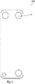
- the heat exchanger 100 may be a single-circuit heat exchanger such as that shown in Fig. 1 , or a dual-circuit heat exchanger such as that shown in Fig. 5 .
- the distributor 30 for a plate heat exchanger comprises: a tube part 31, the tube part 31 having a tube wall 310 and having a first end 311 and a second end 312, with a tube part inner cavity being defined in the tube part 31; a first flange 321 formed at the first end 311, the first flange 321 extending from the first end 311 in a direction away from an axis of the tube part 31, the first flange 321 having an outer edge 3210 remote from the tube part 31; and a connecting protrusion 33, the connecting protrusion 33 projecting from the tube wall 310 of the tube part 31 in a direction away from the axis of the tube part 31, and projecting from the first flange 321 at the inside of the outer edge 3210 of the first flange 321 in a direction towards the second end 312 of the tube part 31; the connecting protrusion 33 has a connecting protrusion wall 330, with a connecting protrusion inner
- the number of through-hole(s) 331 may be one, two or more, and the shape of the through-hole 331 may be round or any other suitable shape.
- the number of connecting protrusion(s) 33 may be one, two or more, and the connecting protrusion 33 may have any suitable shape, e.g. substantially round or rectangular.
- the distributor 30 further comprises: a second flange 322 formed at the second end 312 of the tube part 31, the second flange 322 extending from the second end 312 of the tube part 31 in a direction towards the axis of the tube part 31.
- the first flange 321 and second flange 322 may be perpendicular to the axis of the tube part 31.
- the distributor 30 may be formed from a plate by stamping.
- the tube part 31 may be a truncated-cone-shaped tube part 31, with the diameter of the first end 311 being greater than the diameter of the second end 312; the first flange 321 extends radially outward from the first end 311; and the second flange 322 extends radially inward from the second end 312.
- the first flange 321 and second flange 322 have an annular shape, and have openings therein.
- the distributor 30 is arranged at the channel 11, between adjacent heat transfer plates 10, and is configured to connect the channel 11 to the heat exchange space between the adjacent heat transfer plates 10.
- the first flange 321 is connected to one of the adjacent heat transfer plates 10, and the second flange 322 is connected to the other of the adjacent heat transfer plates 10.
- the distributor 30 is generally provided at the channel that acts as a refrigerant inlet.
- the axial connecting protrusion wall 3301 may be at 1/3 to 2/3 of a distance between the first end 311 and second end 312 of the tube part 31, e.g. may be substantially at the midpoint between the first end 311 and second end 312.
- a distance between an outer edge of the axial connecting protrusion wall 3301 and an edge of the through-hole 331 may be 1 - 10 mm.
- a width of the first flange 321 (i.e. the width thereof in a radial direction) is 1 - 10 mm.
- the distributor 30 further comprises a positioning structure, configured to position the distributor 30 relative to the heat transfer plate 10 of the plate heat exchanger 100.
- the positioning structure may be a positioning protrusion 35, which projects from the first flange 321 at the inside of the outer edge 3210 of the first flange 321 in a direction towards the second end 312 of the tube part 31.
- the positioning protrusion 35 projects from the tube wall 310 of the tube part 31 in a direction away from the axis of the tube part 31, and projects from the first flange 321 at the inside of the outer edge 3210 of the first flange 321 in a direction towards the second end 312 of the tube part 31;
- the positioning protrusion 35 has a positioning protrusion wall 350, with a positioning protrusion inner cavity being defined in the positioning protrusion wall 350, the positioning protrusion inner cavity being in communication with the tube part inner cavity.
- the heat transfer plate 10 of the heat exchanger 100 has a positioning protrusion 15; the positioning protrusion 15 of the heat transfer plate 10 may be a protrusion pressed out of the heat transfer plate 10, or a part that is turned up after cutting open a part of the heat transfer plate 10.
- the positioning protrusion 15 of the heat transfer plate 10 extends (e.g. extends radially) from an edge of the opening 13 in a direction away from the opening, and extends from the heat transfer plate 10 towards one side of the heat transfer plate 10 (one side in the direction in which the heat exchange plates 10 are stacked).
- the positioning protrusion 15 of the heat transfer plate 10 is engaged in the positioning protrusion 35 of the distributor 30, in order to position the distributor 30 relative to the heat transfer plate 10.
- the number of positioning protrusion(s) 35 may be one, two or more. In this way, an angle ⁇ between a line connecting the through-hole 331 to a centre line of the distributor 30, and a horizontal plane passing through the centre line of the distributor 30, is fixed. When the heat exchanger is placed according to requirements of use, the through-hole 331 is below this horizontal plane. That is to say, the angle ⁇ is 0° - 180°; in a preferred solution, ⁇ is 30° - 90°.
- the specific form and quantity of the positioning structure(s) positioning by shape or positioning by engagement slot are possible.
- the positioning structure is a positioning piece projecting from an inner edge of the second flange 322, and the heat transfer plate 10 comprises a positioning notch; the positioning notch of the heat transfer plate 10 extends from the edge of the opening 13 in a direction away from the opening 13, and the positioning piece of the distributor 30 is bent and thereby engaged in the positioning notch of the heat transfer plate 10, such that a part of the positioning piece is bent onto a surface of the heat transfer plate 10, thus locking the distributor 30.
- the positioning structure is a positioning piece projecting from the outer edge 3210 of the first flange 321, and the heat transfer plate 10 comprises a positioning through-hole; the positioning through-hole of the heat transfer plate 10 runs through the heat transfer plate 10, and the positioning piece of the distributor 30 is bent and thereby engaged in the positioning through-hole of the heat transfer plate 10, such that a part of the positioning piece is bent onto a surface of the heat transfer plate 10, thus locking the distributor 30.
- the distributor 30 is pre-fixed to the heat transfer plate 10 by welding or bonding, such that the distributor 30 is positioned relative to the heat transfer plate 10.
- the distributor 30 further comprises: a protruding piece 36 projecting from the outer edge 3210 of the first flange 321 in a direction away from the axis of the tube part 31, or an indentation that is sunk from the outer edge 3210 of the first flange 321 in a direction towards the axis of the tube part 31, to enable an automated production line to identify front and back sides of the distributor 30.
- the height of the distributor 30 may be substantially equal to the distance between those parts of the heat transfer plates 10 that surround the channel 11.
- the distributor requires only two technical processes, namely stamping and punching, using a plate, thus the difficulty of manufacture may be reduced.
- the design of the connecting protrusion 33 and the through-hole 3301 not only ensures excellent distribution, but may also avoid the risk of the through-hole 3301 being blocked by solder, such as copper film, during brazing.
Landscapes
- Engineering & Computer Science (AREA)
- Physics & Mathematics (AREA)
- Thermal Sciences (AREA)
- Mechanical Engineering (AREA)
- General Engineering & Computer Science (AREA)
- Geometry (AREA)
- Heat-Exchange Devices With Radiators And Conduit Assemblies (AREA)
- Details Of Heat-Exchange And Heat-Transfer (AREA)
Abstract
Description
- The embodiments of the present invention relate to a distributor for a plate heat exchanger, and a plate heat exchanger.
- In a plate heat exchanger, a heat exchange space is formed between two adjacent heat transfer plates. Fluid flows into the heat exchange space of the heat exchanger through a connecting pipe, a channel formed in the heat transfer plates, and a distributor. The function of the distributor is to control the distribution of fluid via one or more through-holes.
- An object of the embodiments of the present invention is to provide a distributor for a plate heat exchanger, and a plate heat exchanger, and thereby reduce the difficulty of manufacture of distributors and plate heat exchangers.
- According to an embodiment of the present invention, a distributor for a plate heat exchanger is provided, comprising: a tube part, having a tube wall and having a first end and a second end, with a tube part inner cavity being defined in the tube part; a first flange formed at the first end, the first flange extending from the first end in a direction away from an axis of the tube part, the first flange having an outer edge remote from the tube part; and a connecting protrusion, projecting from the tube wall of the tube part in a direction away from the axis of the tube part, and projecting from the first flange at the inside of the outer edge of the first flange in a direction towards the second end of the tube part; the connecting protrusion having a connecting protrusion wall, with a connecting protrusion inner cavity being defined in the connecting protrusion wall, the connecting protrusion inner cavity being in communication with the tube part inner cavity; the connecting protrusion wall having an axial connecting protrusion wall which faces in the axial direction of the tube part and is remote from the first flange, the axial connecting protrusion wall being between the first end and the second end of the tube part, and having at least one through-hole.
- According to an embodiment of the present invention, the axial connecting protrusion wall is at 1/3 to 2/3 of a distance between the first end and second end of the tube part.
- According to an embodiment of the present invention, a distance between an outer edge of the axial connecting protrusion wall and an edge of the through-hole is 1 - 10 mm.
- According to an embodiment of the present invention, a width of the first flange is 1 - 10 mm.
- According to an embodiment of the present invention, the distributor for a plate heat exchanger further comprises: a positioning structure, configured to position the distributor relative to a heat transfer plate of the plate heat exchanger.
- According to an embodiment of the present invention, the positioning structure is a positioning protrusion, which projects from the first flange at the inside of the outer edge of the first flange in a direction towards the second end of the tube part.
- According to an embodiment of the present invention, the positioning protrusion projects from the tube wall of the tube part in a direction away from the axis of the tube part, and projects from the first flange at the inside of the outer edge of the first flange in a direction towards the second end of the tube part; the positioning protrusion has a positioning protrusion wall, with a positioning protrusion inner cavity being defined in the positioning protrusion wall, the positioning protrusion inner cavity being in communication with the tube part inner cavity.
- According to an embodiment of the present invention, the positioning structure is a positioning piece projecting from an inner edge of the second flange.
- According to an embodiment of the present invention, the positioning structure is a positioning piece projecting from the outer edge of the first flange.
- According to an embodiment of the present invention, the distributor for a plate heat exchanger further comprises: a second flange formed at the second end of the tube part, the second flange extending from the second end of the tube part in a direction towards the axis of the tube part.
- According to an embodiment of the present invention, the first flange and second flange are perpendicular to the axis of the tube part.
- According to an embodiment of the present invention, the distributor is formed from a plate by stamping.
- According to an embodiment of the present invention, the tube part is a truncated-cone-shaped tube part, with a diameter of the first end being greater than a diameter of the second end; the first flange extends radially outward from the first end; and the second flange extends radially inward from the second end.
- According to an embodiment of the present invention, a plate heat exchanger is provided, comprising: a plurality of heat transfer plates; a heat exchange space formed between adjacent heat transfer plates amongst the plurality of heat transfer plates; a channel formed in the heat transfer plates, the channel allowing a heat exchange medium to flow into or out of the heat exchanger, wherein openings of the plurality of heat transfer plates form the channel; and the distributor described above, arranged at at least one said channel.
- According to an embodiment of the present invention, the distributor further comprises: a positioning structure, configured to position the distributor relative to the heat transfer plate of the plate heat exchanger.
- According to an embodiment of the present invention, the positioning structure is a positioning protrusion, which projects from the first flange at the inside of the outer edge of the first flange in a direction towards the second end of the tube part, and the heat transfer plate comprises a positioning protrusion, which is engaged in the positioning protrusion of the distributor.
- According to an embodiment of the present invention, the positioning structure is a positioning piece projecting from an inner edge of the second flange, and the heat transfer plate comprises a positioning notch, which extends from an edge of the opening in a direction away from the opening, and the positioning piece of the distributor is bent and thereby engaged in the positioning notch of the heat transfer plate.
- According to an embodiment of the present invention, the positioning structure is a positioning piece projecting from the outer edge of the first flange, and the heat transfer plate comprises a positioning through-hole which runs through the heat transfer plate, and the positioning piece of the distributor is bent and thereby engaged in the positioning through-hole of the heat transfer plate.
- According to an embodiment of the present invention, the distributor is pre-fixed to the heat transfer plate by welding or bonding, such that the distributor is positioned relative to the heat transfer plate.
- The distributor and plate heat exchanger according to embodiments of the present invention may reduce the difficulty of manufacture of distributors and plate heat exchangers.
-
-
Fig. 1 is a schematic top view of a plate heat exchanger according to an embodiment of the present invention; -
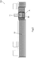
Fig. 2 is a schematic view of the plate heat exchanger shown inFig. 1 , looking obliquely towards the top from the bottom left corner, wherein a port at the lower left corner has been cut open; -
Fig. 3 is a schematic enlarged sectional view of part A of the plate heat exchanger shown inFig. 1 ; -
Fig. 4 is a schematic perspective view of a distributor for a plate heat exchanger according to an embodiment of the present invention; -
Fig. 5 is a schematic top view of a plate heat exchanger according to an embodiment of the present invention; -
Fig. 6 is a schematic partial enlarged sectional view of a plate heat exchanger according to an embodiment of the present invention; and -
Fig. 7 is a schematic top view of a distributor for a plate heat exchanger according to an embodiment of the present invention. - The present invention is explained further below in conjunction with the drawings and particular embodiments.
- As shown in
Figs. 1 - 7 , aplate heat exchanger 100 according to an embodiment of the present invention comprises a plurality ofheat transfer plates 10; a heat exchange space formed between adjacentheat transfer plates 10 amongst the plurality ofheat transfer plates 10; achannel 11 formed in theheat transfer plates 10, thechannel 11 allowing a heat exchange medium (e.g. a refrigerant) to flow into or out of theheat exchanger 100, whereinopenings 13 of the plurality ofheat transfer plates 10 form thechannel 11; and adistributor 30 arranged at at least one saidchannel 11. Theheat exchanger 100 may be a single-circuit heat exchanger such as that shown inFig. 1 , or a dual-circuit heat exchanger such as that shown inFig. 5 . - As shown in
Figs. 4 and6 , thedistributor 30 for a plate heat exchanger according to an embodiment of the present invention comprises: atube part 31, thetube part 31 having atube wall 310 and having afirst end 311 and asecond end 312, with a tube part inner cavity being defined in thetube part 31; afirst flange 321 formed at thefirst end 311, thefirst flange 321 extending from thefirst end 311 in a direction away from an axis of thetube part 31, thefirst flange 321 having anouter edge 3210 remote from thetube part 31; and a connectingprotrusion 33, the connectingprotrusion 33 projecting from thetube wall 310 of thetube part 31 in a direction away from the axis of thetube part 31, and projecting from thefirst flange 321 at the inside of theouter edge 3210 of thefirst flange 321 in a direction towards thesecond end 312 of thetube part 31; the connectingprotrusion 33 has a connectingprotrusion wall 330, with a connecting protrusion inner cavity being defined in the connectingprotrusion wall 330, the connecting protrusion inner cavity being in communication with the tube part inner cavity; the connectingprotrusion wall 330 has an axial connectingprotrusion wall 3301 which faces in the axial direction of thetube part 31 and is remote from thefirst flange 321, the axial connectingprotrusion wall 3301 being between thefirst end 311 and thesecond end 312 of thetube part 31, and having at least one through-hole 331. The number of through-hole(s) 331 may be one, two or more, and the shape of the through-hole 331 may be round or any other suitable shape. The number of connecting protrusion(s) 33 may be one, two or more, and the connectingprotrusion 33 may have any suitable shape, e.g. substantially round or rectangular. - As shown in
Figs. 4 and6 , in an embodiment of the present invention, thedistributor 30 further comprises: asecond flange 322 formed at thesecond end 312 of thetube part 31, thesecond flange 322 extending from thesecond end 312 of thetube part 31 in a direction towards the axis of thetube part 31. Thefirst flange 321 andsecond flange 322 may be perpendicular to the axis of thetube part 31. Thedistributor 30 may be formed from a plate by stamping. According to an example of the present invention, thetube part 31 may be a truncated-cone-shaped tube part 31, with the diameter of thefirst end 311 being greater than the diameter of thesecond end 312; thefirst flange 321 extends radially outward from thefirst end 311; and thesecond flange 322 extends radially inward from thesecond end 312. Thefirst flange 321 andsecond flange 322 have an annular shape, and have openings therein. - As shown in
Fig. 3 , thedistributor 30 is arranged at thechannel 11, between adjacentheat transfer plates 10, and is configured to connect thechannel 11 to the heat exchange space between the adjacentheat transfer plates 10. Thefirst flange 321 is connected to one of the adjacentheat transfer plates 10, and thesecond flange 322 is connected to the other of the adjacentheat transfer plates 10. Thedistributor 30 is generally provided at the channel that acts as a refrigerant inlet. - As shown in
Figs. 4 ,6 and7 , in an embodiment of the present invention, the axial connectingprotrusion wall 3301 may be at 1/3 to 2/3 of a distance between thefirst end 311 andsecond end 312 of thetube part 31, e.g. may be substantially at the midpoint between thefirst end 311 andsecond end 312. A distance between an outer edge of the axial connectingprotrusion wall 3301 and an edge of the through-hole 331 may be 1 - 10 mm. A width of the first flange 321 (i.e. the width thereof in a radial direction) is 1 - 10 mm. - Referring to
Figs. 5 - 7 , in an embodiment of the present invention, thedistributor 30 further comprises a positioning structure, configured to position thedistributor 30 relative to theheat transfer plate 10 of theplate heat exchanger 100. The positioning structure may be apositioning protrusion 35, which projects from thefirst flange 321 at the inside of theouter edge 3210 of thefirst flange 321 in a direction towards thesecond end 312 of thetube part 31. According to an example of the present invention, thepositioning protrusion 35 projects from thetube wall 310 of thetube part 31 in a direction away from the axis of thetube part 31, and projects from thefirst flange 321 at the inside of theouter edge 3210 of thefirst flange 321 in a direction towards thesecond end 312 of thetube part 31; thepositioning protrusion 35 has apositioning protrusion wall 350, with a positioning protrusion inner cavity being defined in thepositioning protrusion wall 350, the positioning protrusion inner cavity being in communication with the tube part inner cavity. According to an example of the present invention, theheat transfer plate 10 of theheat exchanger 100 has apositioning protrusion 15; thepositioning protrusion 15 of theheat transfer plate 10 may be a protrusion pressed out of theheat transfer plate 10, or a part that is turned up after cutting open a part of theheat transfer plate 10. Referring toFig. 6 , thepositioning protrusion 15 of theheat transfer plate 10 extends (e.g. extends radially) from an edge of theopening 13 in a direction away from the opening, and extends from theheat transfer plate 10 towards one side of the heat transfer plate 10 (one side in the direction in which theheat exchange plates 10 are stacked). Thepositioning protrusion 15 of theheat transfer plate 10 is engaged in thepositioning protrusion 35 of thedistributor 30, in order to position thedistributor 30 relative to theheat transfer plate 10. The number of positioning protrusion(s) 35 may be one, two or more. In this way, an angle α between a line connecting the through-hole 331 to a centre line of thedistributor 30, and a horizontal plane passing through the centre line of thedistributor 30, is fixed. When the heat exchanger is placed according to requirements of use, the through-hole 331 is below this horizontal plane. That is to say, the angle α is 0° - 180°; in a preferred solution, α is 30° - 90°. There are no restrictions on the specific form and quantity of the positioning structure(s); positioning by shape or positioning by engagement slot are possible. For example, two positioning protrusions may be formed on a bottom surface of the distributor, or a part of the heat transfer plate may be cut open and then turned up, and at the same time, two matching positioning protrusions may be formed at the same positions on the plate below the distributor. According to an example of the present invention, the positioning structure is a positioning piece projecting from an inner edge of thesecond flange 322, and theheat transfer plate 10 comprises a positioning notch; the positioning notch of theheat transfer plate 10 extends from the edge of theopening 13 in a direction away from theopening 13, and the positioning piece of thedistributor 30 is bent and thereby engaged in the positioning notch of theheat transfer plate 10, such that a part of the positioning piece is bent onto a surface of theheat transfer plate 10, thus locking thedistributor 30. According to another example of the present invention, the positioning structure is a positioning piece projecting from theouter edge 3210 of thefirst flange 321, and theheat transfer plate 10 comprises a positioning through-hole; the positioning through-hole of theheat transfer plate 10 runs through theheat transfer plate 10, and the positioning piece of thedistributor 30 is bent and thereby engaged in the positioning through-hole of theheat transfer plate 10, such that a part of the positioning piece is bent onto a surface of theheat transfer plate 10, thus locking thedistributor 30. According to another example of the present invention, thedistributor 30 is pre-fixed to theheat transfer plate 10 by welding or bonding, such that thedistributor 30 is positioned relative to theheat transfer plate 10. - Referring to
Figs. 5 and7 , in an embodiment of the present invention, thedistributor 30 further comprises: a protrudingpiece 36 projecting from theouter edge 3210 of thefirst flange 321 in a direction away from the axis of thetube part 31, or an indentation that is sunk from theouter edge 3210 of thefirst flange 321 in a direction towards the axis of thetube part 31, to enable an automated production line to identify front and back sides of thedistributor 30. - According to an embodiment of the present invention, the height of the
distributor 30 may be substantially equal to the distance between those parts of theheat transfer plates 10 that surround thechannel 11. - According to an embodiment of the present invention, the distributor requires only two technical processes, namely stamping and punching, using a plate, thus the difficulty of manufacture may be reduced. The design of the connecting
protrusion 33 and the through-hole 3301 not only ensures excellent distribution, but may also avoid the risk of the through-hole 3301 being blocked by solder, such as copper film, during brazing.
Claims (15)
- Distributor for a plate heat exchanger, comprising:a tube part, having a tube wall and having a first end and a second end, with a tube part inner cavity being defined in the tube part;a first flange formed at the first end, the first flange extending from the first end in a direction away from an axis of the tube part, the first flange having an outer edge remote from the tube part; anda connecting protrusion, projecting from the tube wall of the tube part in a direction away from the axis of the tube part, and projecting from the first flange at the inside of the outer edge of the first flange in a direction towards the second end of the tube part; the connecting protrusion having a connecting protrusion wall, with a connecting protrusion inner cavity being defined in the connecting protrusion wall, the connecting protrusion inner cavity being in communication with the tube part inner cavity; the connecting protrusion wall having an axial connecting protrusion wall which faces in the axial direction of the tube part and is remote from the first flange, the axial connecting protrusion wall being between the first end and the second end of the tube part, and having at least one through-hole.
- Distributor for a plate heat exchanger according to Claim 1, wherein:
the axial connecting protrusion wall is at 1/3 to 2/3 of a distance between the first end and second end of the tube part. - Distributor for a plate heat exchanger according to Claim 1, wherein:
a distance between an outer edge of the axial connecting protrusion wall and an edge of the through-hole is 1 - 10 mm. - Distributor for a plate heat exchanger according to Claim 1, wherein:
a width of the first flange is 1 - 10 mm. - Distributor for a plate heat exchanger according to Claim 1, further comprising:
a positioning structure, configured to position the distributor relative to a heat transfer plate of the plate heat exchanger. - Distributor for a plate heat exchanger according to Claim 5, wherein:
the positioning structure is a positioning protrusion, which projects from the first flange at the inside of the outer edge of the first flange in a direction towards the second end of the tube part. - Distributor for a plate heat exchanger according to Claim 6, wherein:
the positioning protrusion projects from the tube wall of the tube part in a direction away from the axis of the tube part, and projects from the first flange at the inside of the outer edge of the first flange in a direction towards the second end of the tube part; the positioning protrusion has a positioning protrusion wall, with a positioning protrusion inner cavity being defined in the positioning protrusion wall, the positioning protrusion inner cavity being in communication with the tube part inner cavity. - Distributor for a plate heat exchanger according to Claim 1, further comprising:
a second flange formed at the second end of the tube part, the second flange extending from the second end of the tube part in a direction towards the axis of the tube part. - Distributor for a plate heat exchanger according to Claim 8, wherein:
the first flange and second flange are perpendicular to the axis of the tube part. - Distributor for a plate heat exchanger according to Claim 1, wherein:
the distributor is formed from a plate by stamping. - Distributor for a plate heat exchanger according to Claim 8, wherein:the tube part is a truncated-cone-shaped tube part, with a diameter of the first end being greater than a diameter of the second end;the first flange extends radially outward from the first end; andthe second flange extends radially inward from the second end.
- Plate heat exchanger, comprising:a plurality of heat transfer plates;a heat exchange space formed between adjacent heat transfer plates amongst the plurality of heat transfer plates;a channel formed in the heat transfer plates, the channel allowing a heat exchange medium to flow into or out of the heat exchanger, wherein openings of the plurality of heat transfer plates form the channel; andthe distributor according to Claim 1, arranged at at least one said channel.
- Plate heat exchanger according to Claim 12, wherein:
the distributor further comprises: a positioning structure, configured to position the distributor relative to the heat transfer plate of the plate heat exchanger. - Plate heat exchanger according to Claim 13, wherein:the positioning structure is a positioning protrusion, which projects from the first flange at the inside of the outer edge of the first flange in a direction towards the second end of the tube part, andthe heat transfer plate comprises a positioning protrusion, which is engaged in the positioning protrusion of the distributor.
- Plate heat exchanger according to Claim 12, wherein:
the distributor is pre-fixed to the heat transfer plate by welding or bonding, such that the distributor is positioned relative to the heat transfer plate.
Applications Claiming Priority (2)
| Application Number | Priority Date | Filing Date | Title |
|---|---|---|---|
| CN202011462217.6A CN114623721A (en) | 2020-12-10 | 2020-12-10 | Distributor for plate heat exchanger and plate heat exchanger |
| CN202022939568.3U CN215003144U (en) | 2020-12-10 | 2020-12-10 | Distributor for plate heat exchanger and plate heat exchanger |
Publications (2)
| Publication Number | Publication Date |
|---|---|
| EP4012323A1 true EP4012323A1 (en) | 2022-06-15 |
| EP4012323B1 EP4012323B1 (en) | 2024-12-25 |
Family
ID=78825159
Family Applications (1)
| Application Number | Title | Priority Date | Filing Date |
|---|---|---|---|
| EP21213035.5A Active EP4012323B1 (en) | 2020-12-10 | 2021-12-08 | Distributor for plate heat exchanger, and plate heat exchanger |
Country Status (4)
| Country | Link |
|---|---|
| US (1) | US11920876B2 (en) |
| EP (1) | EP4012323B1 (en) |
| MX (1) | MX2021015194A (en) |
| PL (1) | PL4012323T3 (en) |
Families Citing this family (4)
| Publication number | Priority date | Publication date | Assignee | Title |
|---|---|---|---|---|
| CN113154910A (en) * | 2020-01-22 | 2021-07-23 | 丹佛斯有限公司 | Plate heat exchanger |
| CN114608368A (en) * | 2020-12-08 | 2022-06-10 | 绍兴三花新能源汽车部件有限公司 | Heat exchanger |
| KR20230148240A (en) * | 2021-02-22 | 2023-10-24 | 스웹 인터네셔널 에이비이 | Brazed plate heat exchanger |
| CN117889585A (en) * | 2024-01-25 | 2024-04-16 | 赤壁银轮工业换热器有限公司 | Plate heat exchanger |
Citations (4)
| Publication number | Priority date | Publication date | Assignee | Title |
|---|---|---|---|---|
| WO2005121685A1 (en) * | 2004-06-14 | 2005-12-22 | Institutt For Energiteknikk | Inlet arrangement for a plate heat exchanger |
| EP3104110A1 (en) * | 2014-01-28 | 2016-12-14 | Danfoss Micro Channel Heat Exchanger (Jiaxing) Co., Ltd. | Board-type heat exchanger |
| WO2019161657A1 (en) * | 2018-02-23 | 2019-08-29 | 江苏宝得换热设备股份有限公司 | Block fluid distributor and manufacturing method therefor |
| US20190331436A1 (en) * | 2018-04-27 | 2019-10-31 | Mahle International Gmbh | Stacked plate heat exchanger |
Family Cites Families (16)
| Publication number | Priority date | Publication date | Assignee | Title |
|---|---|---|---|---|
| SE502984C2 (en) * | 1993-06-17 | 1996-03-04 | Alfa Laval Thermal Ab | Flat heat exchanger with specially designed door sections |
| SE526409C2 (en) * | 2004-01-09 | 2005-09-06 | Alfa Laval Corp Ab | plate heat exchangers |
| SE531241C2 (en) * | 2005-04-13 | 2009-01-27 | Alfa Laval Corp Ab | Plate heat exchanger with substantially uniform cylindrical inlet duct |
| US20070089872A1 (en) * | 2005-10-25 | 2007-04-26 | Kaori Heat Treatment Co., Ltd. | Heat exchanger having flow control device |
| US20070261833A1 (en) * | 2006-05-09 | 2007-11-15 | Kaori Heat Treatment Co., Ltd. | Heat exchanger having different flowing paths |
| US20070261834A1 (en) * | 2006-05-09 | 2007-11-15 | Kaori Heat Treatment Co., Ltd. | Heat exchanger having uneven flowing paths |
| JP5940970B2 (en) * | 2012-02-10 | 2016-06-29 | 株式会社ティラド | Laminate heat exchanger |
| PT2730878T (en) * | 2012-11-07 | 2019-05-30 | Alfa Laval Corp Ab | Plate package and method of making a plate package |
| CN103791759B (en) * | 2014-03-07 | 2016-03-30 | 丹佛斯微通道换热器(嘉兴)有限公司 | Heat exchange plate for plate heat exchanger and plate heat exchanger with heat exchange plate |
| CN106556263B (en) * | 2015-09-28 | 2019-01-25 | 丹佛斯微通道换热器(嘉兴)有限公司 | Plate Heat Exchanger |
| SE541284C2 (en) * | 2016-05-30 | 2019-06-11 | Alfa Laval Corp Ab | A plate heat exchanger |
| CN109387111A (en) * | 2017-08-10 | 2019-02-26 | 丹佛斯微通道换热器(嘉兴)有限公司 | Channel pieces and plate heat exchangers for channels of plate heat exchangers |
| CN108195212B (en) * | 2018-02-23 | 2024-05-14 | 江苏宝得换热设备股份有限公司 | Brazing plate type heat exchanger |
| IT201900000665U1 (en) * | 2019-02-27 | 2020-08-27 | Onda S P A | PLATE HEAT EXCHANGER. |
| CN211575949U (en) * | 2020-01-22 | 2020-09-25 | 丹佛斯有限公司 | Plate heat exchanger |
| CN113154910A (en) * | 2020-01-22 | 2021-07-23 | 丹佛斯有限公司 | Plate heat exchanger |
-
2021
- 2021-12-06 US US17/542,598 patent/US11920876B2/en active Active
- 2021-12-08 EP EP21213035.5A patent/EP4012323B1/en active Active
- 2021-12-08 PL PL21213035.5T patent/PL4012323T3/en unknown
- 2021-12-09 MX MX2021015194A patent/MX2021015194A/en unknown
Patent Citations (4)
| Publication number | Priority date | Publication date | Assignee | Title |
|---|---|---|---|---|
| WO2005121685A1 (en) * | 2004-06-14 | 2005-12-22 | Institutt For Energiteknikk | Inlet arrangement for a plate heat exchanger |
| EP3104110A1 (en) * | 2014-01-28 | 2016-12-14 | Danfoss Micro Channel Heat Exchanger (Jiaxing) Co., Ltd. | Board-type heat exchanger |
| WO2019161657A1 (en) * | 2018-02-23 | 2019-08-29 | 江苏宝得换热设备股份有限公司 | Block fluid distributor and manufacturing method therefor |
| US20190331436A1 (en) * | 2018-04-27 | 2019-10-31 | Mahle International Gmbh | Stacked plate heat exchanger |
Also Published As
| Publication number | Publication date |
|---|---|
| PL4012323T3 (en) | 2025-04-14 |
| US20220187031A1 (en) | 2022-06-16 |
| EP4012323B1 (en) | 2024-12-25 |
| US11920876B2 (en) | 2024-03-05 |
| MX2021015194A (en) | 2022-06-13 |
Similar Documents
| Publication | Publication Date | Title |
|---|---|---|
| US11920876B2 (en) | Distributor for plate heat exchanger and plate heat exchanger | |
| CN215003144U (en) | Distributor for plate heat exchanger and plate heat exchanger | |
| EP2977706B1 (en) | Manifold and heat exchanger having same | |
| CN101858705B (en) | Heat exchanger and partition thereof | |
| EP3816556B1 (en) | Heat exchanger | |
| WO2020238781A1 (en) | Plate heat exchanger | |
| EP3301394B1 (en) | Heat exchanger, header for the same and manufacturing method thereof | |
| JP2002506196A (en) | 3-circuit plate heat exchanger | |
| EP4006477A1 (en) | Plate heat exchanger | |
| CN211575949U (en) | Plate heat exchanger | |
| CN116793118A (en) | Plate heat exchanger | |
| EP2650078B1 (en) | Method for manufacturing refrigerant guide tube of heat exchanger, refrigerant guide tube manufactured using the method and heat exchanger with the refrigerant guide tube | |
| CN114623721A (en) | Distributor for plate heat exchanger and plate heat exchanger | |
| CN112146475B (en) | Collecting pipe and heat exchanger | |
| CN116086219B (en) | Plate heat exchanger with distribution hole structure | |
| US20230032094A1 (en) | Heat exchanger and assembly method therefor | |
| CN216081099U (en) | Compact heat exchanger | |
| EP4095478B1 (en) | Plate heat exchanger | |
| CN112033185B (en) | Header box and heat exchanger | |
| CN106959038A (en) | Distributor and plate type heat exchanger for plate type heat exchanger | |
| CN216205544U (en) | Heat exchange plate and compact heat exchanger | |
| CN116659275B (en) | Plate heat exchanger | |
| EP4145591A1 (en) | Heat exchange device | |
| WO2011039563A1 (en) | A heat exchanger | |
| US20210180883A1 (en) | Heat exchanger with one-piece through fittings |
Legal Events
| Date | Code | Title | Description |
|---|---|---|---|
| PUAI | Public reference made under article 153(3) epc to a published international application that has entered the european phase |
Free format text: ORIGINAL CODE: 0009012 |
|
| STAA | Information on the status of an ep patent application or granted ep patent |
Free format text: STATUS: THE APPLICATION HAS BEEN PUBLISHED |
|
| AK | Designated contracting states |
Kind code of ref document: A1 Designated state(s): AL AT BE BG CH CY CZ DE DK EE ES FI FR GB GR HR HU IE IS IT LI LT LU LV MC MK MT NL NO PL PT RO RS SE SI SK SM TR |
|
| STAA | Information on the status of an ep patent application or granted ep patent |
Free format text: STATUS: REQUEST FOR EXAMINATION WAS MADE |
|
| 17P | Request for examination filed |
Effective date: 20220905 |
|
| RBV | Designated contracting states (corrected) |
Designated state(s): AL AT BE BG CH CY CZ DE DK EE ES FI FR GB GR HR HU IE IS IT LI LT LU LV MC MK MT NL NO PL PT RO RS SE SI SK SM TR |
|
| P01 | Opt-out of the competence of the unified patent court (upc) registered |
Effective date: 20230713 |
|
| STAA | Information on the status of an ep patent application or granted ep patent |
Free format text: STATUS: EXAMINATION IS IN PROGRESS |
|
| 17Q | First examination report despatched |
Effective date: 20230927 |
|
| GRAP | Despatch of communication of intention to grant a patent |
Free format text: ORIGINAL CODE: EPIDOSNIGR1 |
|
| STAA | Information on the status of an ep patent application or granted ep patent |
Free format text: STATUS: GRANT OF PATENT IS INTENDED |
|
| INTG | Intention to grant announced |
Effective date: 20240808 |
|
| GRAS | Grant fee paid |
Free format text: ORIGINAL CODE: EPIDOSNIGR3 |
|
| GRAA | (expected) grant |
Free format text: ORIGINAL CODE: 0009210 |
|
| STAA | Information on the status of an ep patent application or granted ep patent |
Free format text: STATUS: THE PATENT HAS BEEN GRANTED |
|
| AK | Designated contracting states |
Kind code of ref document: B1 Designated state(s): AL AT BE BG CH CY CZ DE DK EE ES FI FR GB GR HR HU IE IS IT LI LT LU LV MC MK MT NL NO PL PT RO RS SE SI SK SM TR |
|
| REG | Reference to a national code |
Ref country code: GB Ref legal event code: FG4D |
|
| REG | Reference to a national code |
Ref country code: CH Ref legal event code: EP |
|
| REG | Reference to a national code |
Ref country code: DE Ref legal event code: R096 Ref document number: 602021023828 Country of ref document: DE |
|
| REG | Reference to a national code |
Ref country code: IE Ref legal event code: FG4D |
|
| REG | Reference to a national code |
Ref country code: SE Ref legal event code: TRGR |
|
| REG | Reference to a national code |
Ref country code: SK Ref legal event code: T3 Ref document number: E 45689 Country of ref document: SK |
|
| REG | Reference to a national code |
Ref country code: LT Ref legal event code: MG9D |
|
| PG25 | Lapsed in a contracting state [announced via postgrant information from national office to epo] |
Ref country code: HR Free format text: LAPSE BECAUSE OF FAILURE TO SUBMIT A TRANSLATION OF THE DESCRIPTION OR TO PAY THE FEE WITHIN THE PRESCRIBED TIME-LIMIT Effective date: 20241225 |
|
| PG25 | Lapsed in a contracting state [announced via postgrant information from national office to epo] |
Ref country code: FI Free format text: LAPSE BECAUSE OF FAILURE TO SUBMIT A TRANSLATION OF THE DESCRIPTION OR TO PAY THE FEE WITHIN THE PRESCRIBED TIME-LIMIT Effective date: 20241225 |
|
| PG25 | Lapsed in a contracting state [announced via postgrant information from national office to epo] |
Ref country code: BG Free format text: LAPSE BECAUSE OF FAILURE TO SUBMIT A TRANSLATION OF THE DESCRIPTION OR TO PAY THE FEE WITHIN THE PRESCRIBED TIME-LIMIT Effective date: 20241225 |
|
| PG25 | Lapsed in a contracting state [announced via postgrant information from national office to epo] |
Ref country code: NO Free format text: LAPSE BECAUSE OF FAILURE TO SUBMIT A TRANSLATION OF THE DESCRIPTION OR TO PAY THE FEE WITHIN THE PRESCRIBED TIME-LIMIT Effective date: 20250325 |
|
| PG25 | Lapsed in a contracting state [announced via postgrant information from national office to epo] |
Ref country code: GR Free format text: LAPSE BECAUSE OF FAILURE TO SUBMIT A TRANSLATION OF THE DESCRIPTION OR TO PAY THE FEE WITHIN THE PRESCRIBED TIME-LIMIT Effective date: 20250326 Ref country code: LV Free format text: LAPSE BECAUSE OF FAILURE TO SUBMIT A TRANSLATION OF THE DESCRIPTION OR TO PAY THE FEE WITHIN THE PRESCRIBED TIME-LIMIT Effective date: 20241225 |
|
| PG25 | Lapsed in a contracting state [announced via postgrant information from national office to epo] |
Ref country code: RS Free format text: LAPSE BECAUSE OF FAILURE TO SUBMIT A TRANSLATION OF THE DESCRIPTION OR TO PAY THE FEE WITHIN THE PRESCRIBED TIME-LIMIT Effective date: 20250325 |
|
| REG | Reference to a national code |
Ref country code: NL Ref legal event code: MP Effective date: 20241225 |
|
| PG25 | Lapsed in a contracting state [announced via postgrant information from national office to epo] |
Ref country code: NL Free format text: LAPSE BECAUSE OF FAILURE TO SUBMIT A TRANSLATION OF THE DESCRIPTION OR TO PAY THE FEE WITHIN THE PRESCRIBED TIME-LIMIT Effective date: 20241225 |
|
| REG | Reference to a national code |
Ref country code: AT Ref legal event code: MK05 Ref document number: 1754473 Country of ref document: AT Kind code of ref document: T Effective date: 20241225 |
|
| PG25 | Lapsed in a contracting state [announced via postgrant information from national office to epo] |
Ref country code: SM Free format text: LAPSE BECAUSE OF FAILURE TO SUBMIT A TRANSLATION OF THE DESCRIPTION OR TO PAY THE FEE WITHIN THE PRESCRIBED TIME-LIMIT Effective date: 20241225 |
|
| PG25 | Lapsed in a contracting state [announced via postgrant information from national office to epo] |
Ref country code: ES Free format text: LAPSE BECAUSE OF FAILURE TO SUBMIT A TRANSLATION OF THE DESCRIPTION OR TO PAY THE FEE WITHIN THE PRESCRIBED TIME-LIMIT Effective date: 20241225 |
|
| PG25 | Lapsed in a contracting state [announced via postgrant information from national office to epo] |
Ref country code: IS Free format text: LAPSE BECAUSE OF FAILURE TO SUBMIT A TRANSLATION OF THE DESCRIPTION OR TO PAY THE FEE WITHIN THE PRESCRIBED TIME-LIMIT Effective date: 20250425 |
|
| PG25 | Lapsed in a contracting state [announced via postgrant information from national office to epo] |
Ref country code: PT Free format text: LAPSE BECAUSE OF FAILURE TO SUBMIT A TRANSLATION OF THE DESCRIPTION OR TO PAY THE FEE WITHIN THE PRESCRIBED TIME-LIMIT Effective date: 20250428 |
|
| PG25 | Lapsed in a contracting state [announced via postgrant information from national office to epo] |
Ref country code: EE Free format text: LAPSE BECAUSE OF FAILURE TO SUBMIT A TRANSLATION OF THE DESCRIPTION OR TO PAY THE FEE WITHIN THE PRESCRIBED TIME-LIMIT Effective date: 20241225 |
|
| PG25 | Lapsed in a contracting state [announced via postgrant information from national office to epo] |
Ref country code: AT Free format text: LAPSE BECAUSE OF FAILURE TO SUBMIT A TRANSLATION OF THE DESCRIPTION OR TO PAY THE FEE WITHIN THE PRESCRIBED TIME-LIMIT Effective date: 20241225 Ref country code: RO Free format text: LAPSE BECAUSE OF FAILURE TO SUBMIT A TRANSLATION OF THE DESCRIPTION OR TO PAY THE FEE WITHIN THE PRESCRIBED TIME-LIMIT Effective date: 20241225 |
|
| PG25 | Lapsed in a contracting state [announced via postgrant information from national office to epo] |
Ref country code: CZ Free format text: LAPSE BECAUSE OF FAILURE TO SUBMIT A TRANSLATION OF THE DESCRIPTION OR TO PAY THE FEE WITHIN THE PRESCRIBED TIME-LIMIT Effective date: 20241225 |
|
| REG | Reference to a national code |
Ref country code: DE Ref legal event code: R097 Ref document number: 602021023828 Country of ref document: DE |
|
| PG25 | Lapsed in a contracting state [announced via postgrant information from national office to epo] |
Ref country code: DK Free format text: LAPSE BECAUSE OF FAILURE TO SUBMIT A TRANSLATION OF THE DESCRIPTION OR TO PAY THE FEE WITHIN THE PRESCRIBED TIME-LIMIT Effective date: 20241225 |
|
| PLBE | No opposition filed within time limit |
Free format text: ORIGINAL CODE: 0009261 |
|
| STAA | Information on the status of an ep patent application or granted ep patent |
Free format text: STATUS: NO OPPOSITION FILED WITHIN TIME LIMIT |
|
| REG | Reference to a national code |
Ref country code: CH Ref legal event code: L10 Free format text: ST27 STATUS EVENT CODE: U-0-0-L10-L00 (AS PROVIDED BY THE NATIONAL OFFICE) Effective date: 20251105 |
|
| 26N | No opposition filed |
Effective date: 20250926 |
|
| PGFP | Annual fee paid to national office [announced via postgrant information from national office to epo] |
Ref country code: DE Payment date: 20251104 Year of fee payment: 5 |
|
| PGFP | Annual fee paid to national office [announced via postgrant information from national office to epo] |
Ref country code: IT Payment date: 20251121 Year of fee payment: 5 |
|
| PGFP | Annual fee paid to national office [announced via postgrant information from national office to epo] |
Ref country code: FR Payment date: 20251117 Year of fee payment: 5 |
|
| PGFP | Annual fee paid to national office [announced via postgrant information from national office to epo] |
Ref country code: SE Payment date: 20251112 Year of fee payment: 5 |
|
| PGFP | Annual fee paid to national office [announced via postgrant information from national office to epo] |
Ref country code: PL Payment date: 20251117 Year of fee payment: 5 |
|
| PGFP | Annual fee paid to national office [announced via postgrant information from national office to epo] |
Ref country code: SK Payment date: 20251112 Year of fee payment: 5 |
|
| PG25 | Lapsed in a contracting state [announced via postgrant information from national office to epo] |
Ref country code: LT Free format text: LAPSE BECAUSE OF FAILURE TO SUBMIT A TRANSLATION OF THE DESCRIPTION OR TO PAY THE FEE WITHIN THE PRESCRIBED TIME-LIMIT Effective date: 20241225 |
|
| PG25 | Lapsed in a contracting state [announced via postgrant information from national office to epo] |
Ref country code: MC Free format text: LAPSE BECAUSE OF FAILURE TO SUBMIT A TRANSLATION OF THE DESCRIPTION OR TO PAY THE FEE WITHIN THE PRESCRIBED TIME-LIMIT Effective date: 20241225 |
|
| REG | Reference to a national code |
Ref country code: CH Ref legal event code: H13 Free format text: ST27 STATUS EVENT CODE: U-0-0-H10-H13 (AS PROVIDED BY THE NATIONAL OFFICE) Effective date: 20260723 |