EP4012307A1 - Refrigerator - Google Patents
Refrigerator Download PDFInfo
- Publication number
- EP4012307A1 EP4012307A1 EP20849414.6A EP20849414A EP4012307A1 EP 4012307 A1 EP4012307 A1 EP 4012307A1 EP 20849414 A EP20849414 A EP 20849414A EP 4012307 A1 EP4012307 A1 EP 4012307A1
- Authority
- EP
- European Patent Office
- Prior art keywords
- ice making
- chamber door
- door
- ice
- storage chamber
- Prior art date
- Legal status (The legal status is an assumption and is not a legal conclusion. Google has not performed a legal analysis and makes no representation as to the accuracy of the status listed.)
- Granted
Links
Images


Classifications
-
- F—MECHANICAL ENGINEERING; LIGHTING; HEATING; WEAPONS; BLASTING
- F25—REFRIGERATION OR COOLING; COMBINED HEATING AND REFRIGERATION SYSTEMS; HEAT PUMP SYSTEMS; MANUFACTURE OR STORAGE OF ICE; LIQUEFACTION SOLIDIFICATION OF GASES
- F25D—REFRIGERATORS; COLD ROOMS; ICE-BOXES; COOLING OR FREEZING APPARATUS NOT OTHERWISE PROVIDED FOR
- F25D11/00—Self-contained movable devices, e.g. domestic refrigerators
- F25D11/02—Self-contained movable devices, e.g. domestic refrigerators with cooling compartments at different temperatures
-
- F—MECHANICAL ENGINEERING; LIGHTING; HEATING; WEAPONS; BLASTING
- F25—REFRIGERATION OR COOLING; COMBINED HEATING AND REFRIGERATION SYSTEMS; HEAT PUMP SYSTEMS; MANUFACTURE OR STORAGE OF ICE; LIQUEFACTION SOLIDIFICATION OF GASES
- F25C—PRODUCING, WORKING OR HANDLING ICE
- F25C5/00—Working or handling ice
- F25C5/20—Distributing ice
- F25C5/22—Distributing ice particularly adapted for household refrigerators
-
- F—MECHANICAL ENGINEERING; LIGHTING; HEATING; WEAPONS; BLASTING
- F25—REFRIGERATION OR COOLING; COMBINED HEATING AND REFRIGERATION SYSTEMS; HEAT PUMP SYSTEMS; MANUFACTURE OR STORAGE OF ICE; LIQUEFACTION SOLIDIFICATION OF GASES
- F25C—PRODUCING, WORKING OR HANDLING ICE
- F25C1/00—Producing ice
-
- F—MECHANICAL ENGINEERING; LIGHTING; HEATING; WEAPONS; BLASTING
- F25—REFRIGERATION OR COOLING; COMBINED HEATING AND REFRIGERATION SYSTEMS; HEAT PUMP SYSTEMS; MANUFACTURE OR STORAGE OF ICE; LIQUEFACTION SOLIDIFICATION OF GASES
- F25D—REFRIGERATORS; COLD ROOMS; ICE-BOXES; COOLING OR FREEZING APPARATUS NOT OTHERWISE PROVIDED FOR
- F25D17/00—Arrangements for circulating cooling fluids; Arrangements for circulating gas, e.g. air, within refrigerated spaces
- F25D17/04—Arrangements for circulating cooling fluids; Arrangements for circulating gas, e.g. air, within refrigerated spaces for circulating air, e.g. by convection
-
- F—MECHANICAL ENGINEERING; LIGHTING; HEATING; WEAPONS; BLASTING
- F25—REFRIGERATION OR COOLING; COMBINED HEATING AND REFRIGERATION SYSTEMS; HEAT PUMP SYSTEMS; MANUFACTURE OR STORAGE OF ICE; LIQUEFACTION SOLIDIFICATION OF GASES
- F25D—REFRIGERATORS; COLD ROOMS; ICE-BOXES; COOLING OR FREEZING APPARATUS NOT OTHERWISE PROVIDED FOR
- F25D23/00—General constructional features
- F25D23/02—Doors; Covers
-
- F—MECHANICAL ENGINEERING; LIGHTING; HEATING; WEAPONS; BLASTING
- F25—REFRIGERATION OR COOLING; COMBINED HEATING AND REFRIGERATION SYSTEMS; HEAT PUMP SYSTEMS; MANUFACTURE OR STORAGE OF ICE; LIQUEFACTION SOLIDIFICATION OF GASES
- F25D—REFRIGERATORS; COLD ROOMS; ICE-BOXES; COOLING OR FREEZING APPARATUS NOT OTHERWISE PROVIDED FOR
- F25D23/00—General constructional features
- F25D23/02—Doors; Covers
- F25D23/025—Secondary closures
-
- F—MECHANICAL ENGINEERING; LIGHTING; HEATING; WEAPONS; BLASTING
- F25—REFRIGERATION OR COOLING; COMBINED HEATING AND REFRIGERATION SYSTEMS; HEAT PUMP SYSTEMS; MANUFACTURE OR STORAGE OF ICE; LIQUEFACTION SOLIDIFICATION OF GASES
- F25D—REFRIGERATORS; COLD ROOMS; ICE-BOXES; COOLING OR FREEZING APPARATUS NOT OTHERWISE PROVIDED FOR
- F25D23/00—General constructional features
- F25D23/12—Arrangements of compartments additional to cooling compartments; Combinations of refrigerators with other equipment, e.g. stove
-
- F—MECHANICAL ENGINEERING; LIGHTING; HEATING; WEAPONS; BLASTING
- F25—REFRIGERATION OR COOLING; COMBINED HEATING AND REFRIGERATION SYSTEMS; HEAT PUMP SYSTEMS; MANUFACTURE OR STORAGE OF ICE; LIQUEFACTION SOLIDIFICATION OF GASES
- F25D—REFRIGERATORS; COLD ROOMS; ICE-BOXES; COOLING OR FREEZING APPARATUS NOT OTHERWISE PROVIDED FOR
- F25D2323/00—General constructional features not provided for in other groups of this subclass
- F25D2323/02—Details of doors or covers not otherwise covered
- F25D2323/023—Door in door constructions
Definitions
- the present invention relates to household electrical appliance, and particularly to a refrigerator.
- a door of a refrigerator is usually provided with an ice making chamber for mounting an ice maker and a dispenser for dispensing ice.
- the ice making chamber has an opening towards the interior of the cabinet of the refrigerator, and an ice making chamber door for opening or closing the ice making chamber is mounted at the opening.
- the present invention provides a refrigerator which is capable of reducing leakage of cold air from the interior of the cabinet of the refrigerator and meanwhile preventing external pollutants such as dust from entering the dispenser, by providing an ice making chamber door and an auxiliary door on a front surface of the storage chamber door of the refrigerator.
- the present invention provides a refrigerator, comprising:
- auxiliary door is pivotally connected to the storage chamber door and completely covers the front surface of the ice making chamber door and the storage chamber door.
- a further improvement as an embodiment of the present invention wherein the ice making chamber door is pivotally mounted to the storage chamber door, and a pivot axis of the ice making chamber door is parallel to the pivot axis of the storage chamber door.
- a further improvement as an embodiment of the present invention wherein the ice making chamber door is pivotally mounted to the storage chamber door, and a pivot axis of the ice making chamber door is perpendicular to the pivot axis of the storage chamber door.
- auxiliary door is pivotally connected to the storage chamber door and completely covers the front surface of the storage chamber door, and the auxiliary door is provided with an ice chamber opening corresponding to the ice making chamber.
- a further improvement as an embodiment of the present invention wherein the ice making chamber door covers a front surface of the storage chamber door and has an ice-dispensing opening, and the auxiliary door is pivotally connected to the ice making chamber door and configured to open or close the ice-dispensing opening.
- a further improvement as an embodiment of the present invention wherein the storage chamber door and the ice making chamber door both have a heat insulating layer, and the auxiliary door is configured to limit heat insulation.
- the storage space comprises a refrigerating chamber and a freezing chamber located below the refrigerating chamber, an ice making evaporation chamber and a freezing evaporation chamber are disposed in the freezing chamber, the freezing evaporation chamber can communicate with the storage space, and the ice making evaporation chamber is communicated with the ice making chamber through an ice making air duct.
- the ice making air duct is disposed on a sidewall of the cabinet and comprises an air supply duct and an air return duct, an air supply inlet of the air supply duct and an air return outlet of the air return duct are both disposed on the sidewall of the cabinet, and the ice making chamber is provided with an ice making air inlet and an ice making air outlet corresponding to the air supply inlet and the air return outlet respectively; when the storage chamber door is closed, the air supply inlet and the air return outlet are respectively connected to the ice making air inlet and the ice making air outlet to supply cold air to the ice making chamber.
- the refrigerator according to the present invention can prevent dust from entering the dispenser while reducing the leakage of cold air, thereby providing a good experience to the user.
- FIG. 1 it illustrates a preferred embodiment of a refrigerator 100 according to the present invention.
- the refrigerator 100 comprises a cabinet 110 and a storage chamber door 120, a storage space is formed in the cabinet 110, and the storage chamber door 120 is pivotally connected to the cabinet 110 to open or close the storage space.
- the storage chamber door 120 comprises a refrigerating chamber door and a freezing chamber door.
- An ice making chamber 130 is provided on a front surface of the storage chamber door 120, the ice making chamber 130 is inwardly recessed, i.e., the ice making chamber 130 is recessed towards the interior of the cabinet 110, and has an opening facing towards outside the cabinet 110.
- An ice maker and an ice bin are mounted in the ice making chamber 130, and the ice bin is located below the ice maker and configured to receive ice made by the ice maker.
- the front surface of the storage chamber door 120 is provided with a dispenser 160 for discharging ice from the ice bin. When the storage chamber door 120 is closed, the user may operate the dispenser 160 to dispense ice.
- the refrigerator 100 further comprises an ice making chamber door 140 and an auxiliary door 150. Both the ice making chamber door 140 and the auxiliary door 150 are mounted on the front surface of the storage chamber door 120, the ice making chamber door 140 is used to open or close the storage chamber door 120, the auxiliary door 150 is pivotally connected to the storage chamber door 120 and completely covers the front surface of the ice making chamber door 140 and the storage chamber 120.
- a locking mechanism (not shown) is disposed between the auxiliary door 150 and the storage chamber door 120 to lock the auxiliary door 150 on the storage chamber door 120 such that the user can pull the auxiliary door 150 to drive the storage chamber door 120 to open or close the storage space.
- the user When the user uses the dispenser 160 to dispense ice, the user needs to open the auxiliary door 150 first, i.e., operate the locking mechanism to separate the auxiliary door 150 from the storage chamber door 120.
- the auxiliary door 150 By providing the ice making chamber door 140 and the auxiliary door 150 completely covering the storage chamber door 120 on the front surface of the storage chamber door 120, the user can open the auxiliary door 150 and selectively use the dispenser 160 to take ice or open the ice making chamber 130 door 140 to take out the ice bin to take ice, which can reduce the leakage of cold air from the storage space during ice taking.
- the auxiliary door 150 can prevent the external dust from entering the ice making chamber 130 and the dispenser 160, which can reduce the user's cleaning times, and prevent ice cubes from being contaminated during ice dispensing.
- the auxiliary door 150 and the ice making chamber door 140 are both pivotally connected to the storage chamber door 120, the auxiliary door 150 and the ice making chamber door 140 are arranged in parallel vertically.
- the auxiliary door 150 may also completely cover the front surface of the storage chamber, an ice chamber opening corresponding to the ice making chamber door 140 is provided on the storage chamber door 120, and the ice making chamber door 140 is exposed to the outside through the ice chamber opening.
- the auxiliary door 150 and the ice making chamber door 140 are both exposed outside, and the user may selectively open the auxiliary door 150 or the ice making chamber door 140, and operate conveniently.
- the ice making chamber door 140 may also completely cover the front surface of the storage chamber door 120, and an ice dispensing opening 161 may be disposed on the ice making chamber door 140.
- the user may operate the dispenser 160 to take ice through the ice dispensing opening 161 in a state that the ice making chamber door 140 is closed.
- the auxiliary door 150 is disposed at the ice dispensing opening 161 to open or close the ice dispensing opening.
- the auxiliary door 150 is pivotally connected to the ice making chamber door 140, a locking mechanism is disposed between the auxiliary door 150 and the ice making chamber door 140 to fix the auxiliary door 150 operably and fixedly to the ice making chamber door 140.
- the user operates the locking mechanism to open the auxiliary door 150 to dispense ice through the dispenser 160.
- the user needs to open the ice making chamber 130, he only needs to open the ice making chamber door 140, which is convenient and quick.
- auxiliary door 150 and the ice making chamber door 140 are both pivotally connected to the storage chamber door 120, a pivot axis of the auxiliary door 150 is parallel to the pivot axis of the storage chamber door 120 to facilitate installation and manufacture, the pivot axis of the ice making chamber door 140 is parallel to the pivot axis of the storage chamber door 120, and the user can turn in the same turning direction as turning the storage chamber door 120 to open and close the auxiliary door 150 and ice making chamber door 140 with better experience.
- the pivot axis of the ice making chamber door 140 may be perpendicular to the pivot axis of the storage chamber door 120.
- both the storage chamber door 120 and the ice making chamber door 140 have a heat insulating layer to prevent leakage of cold air out of the storage space and the ice making chamber 130.
- a heat-insulating foaming material or mount a vacuum heat insulating plate, or employ a combination of the two.
- the auxiliary door 150 is configured to limit the heat insulation, that is, the auxiliary door 150 is not foamed or filled with other heat-insulating materials.
- the auxiliary door 150 may be made of a material such as plastic, metal, transparent glass, thereby reducing the overall thickness of the storage chamber door 120 and the auxiliary door 150.
- the storage space comprises a refrigerating chamber 111 and a freezing chamber 112 located below the refrigerating chamber 111.
- An ice making evaporation chamber 170 and a freezing evaporation chamber are disposed in the freezing chamber 112.
- the freezing evaporation chamber delivers cold air to the storage space. Disposing both the ice making evaporation chamber 170 and the freezing evaporation chamber in the freezing cabinet 110 can prevent the evaporation chamber from delivering cold air to the refrigerating chamber and affecting the ice making effect of the refrigerating chamber.
- an ice making air duct is disposed on a sidewall of the cabinet 110 and comprises an air supply duct 180 and an air return duct 190.
- An air supply outlet 181 of the air supply duct 180 and an air return inlet 191 of the air return duct 190 are both disposed on the sidewall of the cabinet 110.
- the ice making chamber is provided with an ice making air inlet 182 and an ice making air outlet 192 corresponding to the air supply inlet and the air return outlet 191, respectively.
- the air supply inlet and the air return outlet 191 are respectively connected to the ice making air inlet 182 and the ice making air outlet 192 to supply cold air to the ice making chamber 130.
- the ice making evaporation chamber 170 communicates with the ice making chamber 130 through the ice making air duct, and only delivers cold air to the ice making chamber 130 to prevent the odor of the food in the storage space from entering the ice making chamber 130.
Landscapes
- Engineering & Computer Science (AREA)
- Physics & Mathematics (AREA)
- Mechanical Engineering (AREA)
- Thermal Sciences (AREA)
- General Engineering & Computer Science (AREA)
- Chemical & Material Sciences (AREA)
- Combustion & Propulsion (AREA)
- Devices That Are Associated With Refrigeration Equipment (AREA)
- Cold Air Circulating Systems And Constructional Details In Refrigerators (AREA)
- Refrigerator Housings (AREA)
Abstract
Description
- The present invention relates to household electrical appliance, and particularly to a refrigerator.
- To satisfy users' pluralistic demands, a door of a refrigerator is usually provided with an ice making chamber for mounting an ice maker and a dispenser for dispensing ice. Usually, the ice making chamber has an opening towards the interior of the cabinet of the refrigerator, and an ice making chamber door for opening or closing the ice making chamber is mounted at the opening. When the user needs to repair the ice maker or take a large amount of ice, he needs to open the door of the refrigerator and then open the door of the ice making chamber, which is prone to cause leakage of a large amount of cold air from the interior of the cabinet of the refrigerator; furthermore, the dispenser is generally exposed out of the refrigerator, and external dust is apt to enter the dispenser and cause contamination.
- The present invention provides a refrigerator which is capable of reducing leakage of cold air from the interior of the cabinet of the refrigerator and meanwhile preventing external pollutants such as dust from entering the dispenser, by providing an ice making chamber door and an auxiliary door on a front surface of the storage chamber door of the refrigerator.
- To achieve the object, the present invention provides a refrigerator, comprising:
- a cabinet in which a storage space is formed;
- a storage chamber door pivotally connected to the cabinet and configured to open or close the storage space;
- wherein the refrigerator further comprises an ice making chamber which is formed on a front surface of the storage chamber door and inwardly recessed to receive an ice maker and an ice bin;
- a dispenser disposed at the front surface of the storage chamber door and configured to discharge ice from the ice bin;
- an ice making chamber door mounted to the front surface of the storage chamber door and configured to open or close the ice making chamber;
- an auxiliary door pivotally connected to the storage chamber door or the ice making chamber door and completely covering the dispenser.
- A further improvement as an embodiment of the present invention, wherein a pivot axis of the auxiliary door is parallel to the pivot axis of the storage chamber door.
- A further improvement as an embodiment of the present invention, wherein the auxiliary door is pivotally connected to the storage chamber door and completely covers the front surface of the ice making chamber door and the storage chamber door.
- A further improvement as an embodiment of the present invention, wherein the ice making chamber door is pivotally mounted to the storage chamber door, and a pivot axis of the ice making chamber door is parallel to the pivot axis of the storage chamber door.
- A further improvement as an embodiment of the present invention, wherein the ice making chamber door is pivotally mounted to the storage chamber door, and a pivot axis of the ice making chamber door is perpendicular to the pivot axis of the storage chamber door.
- A further improvement as an embodiment of the present invention, wherein the auxiliary door is pivotally connected to the storage chamber door and completely covers the front surface of the storage chamber door, and the auxiliary door is provided with an ice chamber opening corresponding to the ice making chamber.
- A further improvement as an embodiment of the present invention, wherein the ice making chamber door covers a front surface of the storage chamber door and has an ice-dispensing opening, and the auxiliary door is pivotally connected to the ice making chamber door and configured to open or close the ice-dispensing opening.
- A further improvement as an embodiment of the present invention, wherein the storage chamber door and the ice making chamber door both have a heat insulating layer, and the auxiliary door is configured to limit heat insulation.
- A further improvement as an embodiment of the present invention, wherein the storage space comprises a refrigerating chamber and a freezing chamber located below the refrigerating chamber, an ice making evaporation chamber and a freezing evaporation chamber are disposed in the freezing chamber, the freezing evaporation chamber can communicate with the storage space, and the ice making evaporation chamber is communicated with the ice making chamber through an ice making air duct.
- A further improvement as an embodiment of the present invention, wherein the ice making air duct is disposed on a sidewall of the cabinet and comprises an air supply duct and an air return duct, an air supply inlet of the air supply duct and an air return outlet of the air return duct are both disposed on the sidewall of the cabinet, and the ice making chamber is provided with an ice making air inlet and an ice making air outlet corresponding to the air supply inlet and the air return outlet respectively; when the storage chamber door is closed, the air supply inlet and the air return outlet are respectively connected to the ice making air inlet and the ice making air outlet to supply cold air to the ice making chamber.
- With the ice making chamber door and the auxiliary door being provided on the external surface of the storage chamber door, the refrigerator according to the present invention can prevent dust from entering the dispenser while reducing the leakage of cold air, thereby providing a good experience to the user.
-
-
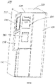
FIG. 1 is a perspective view of a refrigerator in an embodiment of the present invention; -
FIG. 2 is a perspective view of a refrigerator in another embodiment of the present invention; -
FIG. 3 is a perspective view of a refrigerator in a further embodiment of the present invention; -
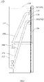
FIG. 4 is a cross-sectional view of the refrigerator shown inFIG. 1 . - Technical solutions in the embodiments of the present invention will be clearly and completely described below with reference to the figures in embodiments of the present invention. Obviously, the described embodiments are merely partial embodiments of the present invention, not all of the embodiments. Based on the embodiments of the present invention, all other embodiments obtained by those having ordinary skill in the art without making inventive efforts fall within the extent of protection of the present invention.
- Referring to
FIG. 1 , it illustrates a preferred embodiment of arefrigerator 100 according to the present invention. Therefrigerator 100 comprises acabinet 110 and astorage chamber door 120, a storage space is formed in thecabinet 110, and thestorage chamber door 120 is pivotally connected to thecabinet 110 to open or close the storage space. Specifically, there are a refrigeratingchamber 111 and afreezing chamber 112 disposed under the refrigeratingchamber 111 in thecabinet 110, and thestorage chamber door 120 comprises a refrigerating chamber door and a freezing chamber door. Anice making chamber 130 is provided on a front surface of thestorage chamber door 120, theice making chamber 130 is inwardly recessed, i.e., theice making chamber 130 is recessed towards the interior of thecabinet 110, and has an opening facing towards outside thecabinet 110. An ice maker and an ice bin are mounted in theice making chamber 130, and the ice bin is located below the ice maker and configured to receive ice made by the ice maker. The front surface of thestorage chamber door 120 is provided with adispenser 160 for discharging ice from the ice bin. When thestorage chamber door 120 is closed, the user may operate thedispenser 160 to dispense ice. - The
refrigerator 100 further comprises an icemaking chamber door 140 and anauxiliary door 150. Both the ice makingchamber door 140 and theauxiliary door 150 are mounted on the front surface of thestorage chamber door 120, the icemaking chamber door 140 is used to open or close thestorage chamber door 120, theauxiliary door 150 is pivotally connected to thestorage chamber door 120 and completely covers the front surface of the ice makingchamber door 140 and thestorage chamber 120. A locking mechanism (not shown) is disposed between theauxiliary door 150 and thestorage chamber door 120 to lock theauxiliary door 150 on thestorage chamber door 120 such that the user can pull theauxiliary door 150 to drive thestorage chamber door 120 to open or close the storage space. When the user uses thedispenser 160 to dispense ice, the user needs to open theauxiliary door 150 first, i.e., operate the locking mechanism to separate theauxiliary door 150 from thestorage chamber door 120. By providing the ice makingchamber door 140 and theauxiliary door 150 completely covering thestorage chamber door 120 on the front surface of thestorage chamber door 120, the user can open theauxiliary door 150 and selectively use thedispenser 160 to take ice or open theice making chamber 130door 140 to take out the ice bin to take ice, which can reduce the leakage of cold air from the storage space during ice taking. Meanwhile, theauxiliary door 150 can prevent the external dust from entering theice making chamber 130 and thedispenser 160, which can reduce the user's cleaning times, and prevent ice cubes from being contaminated during ice dispensing. - Certainly, referring to
FIG. 2 , theauxiliary door 150 and the ice makingchamber door 140 are both pivotally connected to thestorage chamber door 120, theauxiliary door 150 and the ice makingchamber door 140 are arranged in parallel vertically. Certainly, theauxiliary door 150 may also completely cover the front surface of the storage chamber, an ice chamber opening corresponding to the icemaking chamber door 140 is provided on thestorage chamber door 120, and the ice makingchamber door 140 is exposed to the outside through the ice chamber opening. Theauxiliary door 150 and the icemaking chamber door 140 are both exposed outside, and the user may selectively open theauxiliary door 150 or the icemaking chamber door 140, and operate conveniently. - Referring to
FIG. 3 , it may be implemented that the ice makingchamber door 140 may also completely cover the front surface of thestorage chamber door 120, and anice dispensing opening 161 may be disposed on the icemaking chamber door 140. The user may operate thedispenser 160 to take ice through the ice dispensing opening 161 in a state that the icemaking chamber door 140 is closed. Meanwhile, theauxiliary door 150 is disposed at the ice dispensing opening 161 to open or close the ice dispensing opening. Theauxiliary door 150 is pivotally connected to the icemaking chamber door 140, a locking mechanism is disposed between theauxiliary door 150 and the ice makingchamber door 140 to fix theauxiliary door 150 operably and fixedly to the icemaking chamber door 140. The user operates the locking mechanism to open theauxiliary door 150 to dispense ice through thedispenser 160. When the user needs to open theice making chamber 130, he only needs to open the icemaking chamber door 140, which is convenient and quick. - Furthermore, the
auxiliary door 150 and the icemaking chamber door 140 are both pivotally connected to thestorage chamber door 120, a pivot axis of theauxiliary door 150 is parallel to the pivot axis of thestorage chamber door 120 to facilitate installation and manufacture, the pivot axis of the icemaking chamber door 140 is parallel to the pivot axis of thestorage chamber door 120, and the user can turn in the same turning direction as turning thestorage chamber door 120 to open and close theauxiliary door 150 and icemaking chamber door 140 with better experience. Certainly, to facilitate the manufacture and installation, the pivot axis of the icemaking chamber door 140 may be perpendicular to the pivot axis of thestorage chamber door 120. - Furthermore, both the
storage chamber door 120 and the icemaking chamber door 140 have a heat insulating layer to prevent leakage of cold air out of the storage space and theice making chamber 130. Specifically, it is possible to fill a heat-insulating foaming material, or mount a vacuum heat insulating plate, or employ a combination of the two. Theauxiliary door 150 is configured to limit the heat insulation, that is, theauxiliary door 150 is not foamed or filled with other heat-insulating materials. Specifically, theauxiliary door 150 may be made of a material such as plastic, metal, transparent glass, thereby reducing the overall thickness of thestorage chamber door 120 and theauxiliary door 150. - Further, referring to
FIG. 4 , the storage space comprises a refrigeratingchamber 111 and afreezing chamber 112 located below the refrigeratingchamber 111. An ice makingevaporation chamber 170 and a freezing evaporation chamber are disposed in thefreezing chamber 112. The freezing evaporation chamber delivers cold air to the storage space. Disposing both the ice makingevaporation chamber 170 and the freezing evaporation chamber in the freezingcabinet 110 can prevent the evaporation chamber from delivering cold air to the refrigerating chamber and affecting the ice making effect of the refrigerating chamber. - Furthermore, an ice making air duct is disposed on a sidewall of the
cabinet 110 and comprises anair supply duct 180 and anair return duct 190. Anair supply outlet 181 of theair supply duct 180 and anair return inlet 191 of theair return duct 190 are both disposed on the sidewall of thecabinet 110. The ice making chamber is provided with an ice makingair inlet 182 and an ice makingair outlet 192 corresponding to the air supply inlet and theair return outlet 191, respectively. When thestorage chamber door 120 is closed, the air supply inlet and theair return outlet 191 are respectively connected to the ice makingair inlet 182 and the ice makingair outlet 192 to supply cold air to theice making chamber 130. The ice makingevaporation chamber 170 communicates with theice making chamber 130 through the ice making air duct, and only delivers cold air to theice making chamber 130 to prevent the odor of the food in the storage space from entering theice making chamber 130. - It should be understood that although the description is described according to the embodiments, not every embodiment only includes one independent technical solution, that such a description manner is only for the sake of clarity, that those skilled in the art should take the description as an integral part, and that the technical solutions in the embodiments may be suitably combined to form other embodiments understandable by those skilled in the art.
- The detailed descriptions set forth above are merely specific illustrations of feasible embodiments of the present invention, and are not intended to limit the scope of protection of the present invention. All equivalent embodiments or modifications that do not depart from the art spirit of the present invention should fall within the scope of protection of the present invention.
Claims (10)
- A refrigerator, comprising:a cabinet in which a storage space is formed;a storage chamber door pivotally connected to the cabinet and configured to open or close the storage space;wherein the refrigerator further comprises an ice making chamber which is formed on a front surface of the storage chamber door and inwardly recessed to receive an ice maker and an ice bin;a dispenser disposed at the front surface of the storage chamber door and configured to discharge ice from the ice bin;an ice making chamber door mounted to the front surface of the storage chamber door and configured to open or close the ice making chamber;an auxiliary door pivotally connected to the storage chamber door or the ice making chamber door and completely covering the dispenser.
- The refrigerator according to claim 1, wherein a pivot axis of the auxiliary door is parallel to the pivot axis of the storage chamber door.
- The refrigerator according to claim 2, wherein the auxiliary door is pivotally connected to the storage chamber door and completely covers the front surface of the ice making chamber door and the storage chamber door.
- The refrigerator according to claim 3, wherein the ice making chamber door is pivotally mounted to the storage chamber door, and a pivot axis of the ice making chamber door is parallel to the pivot axis of the storage chamber door.
- The refrigerator according to claim 3, wherein the ice making chamber door is pivotally mounted to the storage chamber door, and a pivot axis of the ice making chamber door is perpendicular to the pivot axis of the storage chamber door.
- The refrigerator according to claim 2, wherein the auxiliary door is pivotally connected to the storage chamber door and completely covers the front surface of the storage chamber door, and the auxiliary door is provided with an ice chamber opening corresponding to the ice making chamber.
- The refrigerator according to claim 1, wherein the ice making chamber door covers a front surface of the storage chamber door and has an ice-dispensing opening, and the auxiliary door is pivotally connected to the ice making chamber door and configured to open or close the ice-dispensing opening.
- The refrigerator according to claim 1, wherein the storage chamber door and the ice making chamber door both have a heat insulating layer, and the auxiliary door is configured to limit heat insulation.
- The refrigerator according to claim 1, wherein the storage space comprises a refrigerating chamber and a freezing chamber located below the refrigerating chamber, an ice making evaporation chamber and a freezing evaporation chamber are disposed in the freezing chamber, the freezing evaporation chamber can communicate with the storage space, and the ice making evaporation chamber is communicated with the ice making chamber through an ice making air duct.
- The refrigerator according to claim 9, wherein the ice making air duct is disposed on a sidewall of the cabinet and comprises an air supply duct and an air return duct, an air supply inlet of the air supply duct and an air return outlet of the air return duct are both disposed on the sidewall of the cabinet, and the ice making chamber is provided with an ice making air inlet and an ice making air outlet corresponding to the air supply inlet and the air return outlet respectively; when the storage chamber door is closed, the air supply inlet and the air return outlet are respectively connected to the ice making air inlet and the ice making air outlet to supply cold air to the ice making chamber.
Applications Claiming Priority (2)
| Application Number | Priority Date | Filing Date | Title |
|---|---|---|---|
| CN201910728174.2A CN112344616B (en) | 2019-08-08 | 2019-08-08 | Refrigerator with a door |
| PCT/CN2020/095105 WO2021022893A1 (en) | 2019-08-08 | 2020-06-09 | Refrigerator |
Publications (3)
| Publication Number | Publication Date |
|---|---|
| EP4012307A1 true EP4012307A1 (en) | 2022-06-15 |
| EP4012307A4 EP4012307A4 (en) | 2022-09-21 |
| EP4012307B1 EP4012307B1 (en) | 2024-04-10 |
Family
ID=74367318
Family Applications (1)
| Application Number | Title | Priority Date | Filing Date |
|---|---|---|---|
| EP20849414.6A Active EP4012307B1 (en) | 2019-08-08 | 2020-06-09 | Refrigerator |
Country Status (4)
| Country | Link |
|---|---|
| EP (1) | EP4012307B1 (en) |
| CN (1) | CN112344616B (en) |
| AU (1) | AU2020326927B2 (en) |
| WO (1) | WO2021022893A1 (en) |
Cited By (1)
| Publication number | Priority date | Publication date | Assignee | Title |
|---|---|---|---|---|
| EP4603769A4 (en) * | 2022-10-13 | 2026-01-21 | Lg Electronics Inc | Refrigerator |
Families Citing this family (6)
| Publication number | Priority date | Publication date | Assignee | Title |
|---|---|---|---|---|
| CN117366968A (en) * | 2022-06-29 | 2024-01-09 | 青岛海尔电冰箱有限公司 | refrigerator |
| CN119197027A (en) * | 2023-06-26 | 2024-12-27 | 青岛海尔电冰箱有限公司 | Refrigerator control method, storage medium and refrigerator |
| CN119197023A (en) * | 2023-06-26 | 2024-12-27 | 青岛海尔电冰箱有限公司 | Refrigerator control method, storage medium and refrigerator |
| CN119197026A (en) * | 2023-06-26 | 2024-12-27 | 青岛海尔电冰箱有限公司 | Refrigerator control method, storage medium and refrigerator |
| CN119196999A (en) * | 2023-06-26 | 2024-12-27 | 青岛海尔电冰箱有限公司 | refrigerator |
| WO2025001848A1 (en) * | 2023-06-26 | 2025-01-02 | 青岛海尔电冰箱有限公司 | Refrigerator, refrigerator control method, and storage medium |
Family Cites Families (12)
| Publication number | Priority date | Publication date | Assignee | Title |
|---|---|---|---|---|
| KR101351090B1 (en) * | 2007-01-16 | 2014-01-14 | 삼성전자주식회사 | Refrigerator |
| DE202008011436U1 (en) * | 2008-08-27 | 2009-02-19 | Panasonic Corp., Kadoma | fridge |
| KR20100122230A (en) * | 2009-05-12 | 2010-11-22 | 엘지전자 주식회사 | Refrigerator |
| KR101669421B1 (en) * | 2010-04-05 | 2016-10-26 | 삼성전자주식회사 | Refrigerator |
| KR20120040891A (en) * | 2010-10-20 | 2012-04-30 | 삼성전자주식회사 | Refrigerator |
| KR20130061423A (en) * | 2011-12-01 | 2013-06-11 | 동부대우전자 주식회사 | Refrigerator mounted with home-bar |
| CN102818414A (en) * | 2012-06-06 | 2012-12-12 | 海尔集团公司 | Three-evaporator refrigerator with refrigerating and door-body ice-making functions |
| EP3001125B1 (en) * | 2014-09-23 | 2021-02-24 | Samsung Electronics Co., Ltd. | Refrigerator with an ice-making compartment |
| KR101627935B1 (en) * | 2014-10-22 | 2016-06-07 | 엘지전자 주식회사 | Refrigerator |
| US9816746B1 (en) * | 2016-11-18 | 2017-11-14 | Whirlpool Corporation | Slide out door bin |
| KR102756990B1 (en) * | 2016-12-08 | 2025-01-21 | 삼성전자주식회사 | Refrigerator |
| CN207778902U (en) * | 2017-12-22 | 2018-08-28 | 青岛海尔股份有限公司 | refrigerator |
-
2019
- 2019-08-08 CN CN201910728174.2A patent/CN112344616B/en active Active
-
2020
- 2020-06-09 AU AU2020326927A patent/AU2020326927B2/en active Active
- 2020-06-09 WO PCT/CN2020/095105 patent/WO2021022893A1/en not_active Ceased
- 2020-06-09 EP EP20849414.6A patent/EP4012307B1/en active Active
Cited By (1)
| Publication number | Priority date | Publication date | Assignee | Title |
|---|---|---|---|---|
| EP4603769A4 (en) * | 2022-10-13 | 2026-01-21 | Lg Electronics Inc | Refrigerator |
Also Published As
| Publication number | Publication date |
|---|---|
| AU2020326927A1 (en) | 2022-03-03 |
| AU2020326927B2 (en) | 2023-04-13 |
| EP4012307B1 (en) | 2024-04-10 |
| CN112344616A (en) | 2021-02-09 |
| WO2021022893A1 (en) | 2021-02-11 |
| EP4012307A4 (en) | 2022-09-21 |
| CN112344616B (en) | 2022-04-15 |
Similar Documents
| Publication | Publication Date | Title |
|---|---|---|
| AU2020326927B2 (en) | Refrigerator | |
| US7007500B2 (en) | Dispenser of refrigerator | |
| US3640088A (en) | Household refrigerator including exterior ice service | |
| US7958742B2 (en) | Dispenser and refrigerator having the same | |
| US5442933A (en) | Refrigerator through the door ice dispenser | |
| KR102360680B1 (en) | Refrigerator | |
| KR102615047B1 (en) | Refrigerator | |
| EP3150946B1 (en) | Refrigerator having locking device for ice bucket and method for installing locking device for Ice bucket | |
| US20070289669A1 (en) | Dispenser and refrigerator having the same | |
| CA3083017A1 (en) | Refrigerator integrated with ice maker | |
| EP3745058A1 (en) | Refrigerator | |
| US20110138843A1 (en) | Refrigeration device having an ice-cube maker | |
| CN112361690A (en) | Refrigerator with a door | |
| KR102628625B1 (en) | Refrigerator | |
| US11150004B1 (en) | Integrated ice chute with dispenser housing | |
| US8220283B2 (en) | Ice crushing mechanism | |
| CN221122647U (en) | Refrigerating apparatus | |
| CN101749916A (en) | Refrigerator | |
| CN114719512B (en) | refrigerator | |
| US20240410639A1 (en) | Articulating door latch for a built-in icebox | |
| JP7785193B2 (en) | refrigerator | |
| CN222733078U (en) | Storage equipment | |
| CN121594605A (en) | refrigerator | |
| JP7560375B2 (en) | Ice maker | |
| KR200299613Y1 (en) | A water dispensing lever for the water dispenser of a refrigerator |
Legal Events
| Date | Code | Title | Description |
|---|---|---|---|
| STAA | Information on the status of an ep patent application or granted ep patent |
Free format text: STATUS: THE INTERNATIONAL PUBLICATION HAS BEEN MADE |
|
| PUAI | Public reference made under article 153(3) epc to a published international application that has entered the european phase |
Free format text: ORIGINAL CODE: 0009012 |
|
| STAA | Information on the status of an ep patent application or granted ep patent |
Free format text: STATUS: REQUEST FOR EXAMINATION WAS MADE |
|
| 17P | Request for examination filed |
Effective date: 20220208 |
|
| AK | Designated contracting states |
Kind code of ref document: A1 Designated state(s): AL AT BE BG CH CY CZ DE DK EE ES FI FR GB GR HR HU IE IS IT LI LT LU LV MC MK MT NL NO PL PT RO RS SE SI SK SM TR |
|
| A4 | Supplementary search report drawn up and despatched |
Effective date: 20220823 |
|
| RIC1 | Information provided on ipc code assigned before grant |
Ipc: F25C 5/20 20180101ALI20220817BHEP Ipc: F25D 23/02 20060101ALI20220817BHEP Ipc: F25D 23/12 20060101AFI20220817BHEP |
|
| DAV | Request for validation of the european patent (deleted) | ||
| DAX | Request for extension of the european patent (deleted) | ||
| GRAP | Despatch of communication of intention to grant a patent |
Free format text: ORIGINAL CODE: EPIDOSNIGR1 |
|
| STAA | Information on the status of an ep patent application or granted ep patent |
Free format text: STATUS: GRANT OF PATENT IS INTENDED |
|
| INTG | Intention to grant announced |
Effective date: 20231107 |
|
| GRAS | Grant fee paid |
Free format text: ORIGINAL CODE: EPIDOSNIGR3 |
|
| GRAA | (expected) grant |
Free format text: ORIGINAL CODE: 0009210 |
|
| STAA | Information on the status of an ep patent application or granted ep patent |
Free format text: STATUS: THE PATENT HAS BEEN GRANTED |
|
| AK | Designated contracting states |
Kind code of ref document: B1 Designated state(s): AL AT BE BG CH CY CZ DE DK EE ES FI FR GB GR HR HU IE IS IT LI LT LU LV MC MK MT NL NO PL PT RO RS SE SI SK SM TR |
|
| REG | Reference to a national code |
Ref country code: GB Ref legal event code: FG4D |
|
| REG | Reference to a national code |
Ref country code: CH Ref legal event code: EP |
|
| REG | Reference to a national code |
Ref country code: DE Ref legal event code: R096 Ref document number: 602020028919 Country of ref document: DE |
|
| REG | Reference to a national code |
Ref country code: IE Ref legal event code: FG4D |
|
| REG | Reference to a national code |
Ref country code: LT Ref legal event code: MG9D |
|
| REG | Reference to a national code |
Ref country code: NL Ref legal event code: MP Effective date: 20240410 |
|
| REG | Reference to a national code |
Ref country code: AT Ref legal event code: MK05 Ref document number: 1675283 Country of ref document: AT Kind code of ref document: T Effective date: 20240410 |
|
| PG25 | Lapsed in a contracting state [announced via postgrant information from national office to epo] |
Ref country code: NL Free format text: LAPSE BECAUSE OF FAILURE TO SUBMIT A TRANSLATION OF THE DESCRIPTION OR TO PAY THE FEE WITHIN THE PRESCRIBED TIME-LIMIT Effective date: 20240410 |
|
| PG25 | Lapsed in a contracting state [announced via postgrant information from national office to epo] |
Ref country code: NL Free format text: LAPSE BECAUSE OF FAILURE TO SUBMIT A TRANSLATION OF THE DESCRIPTION OR TO PAY THE FEE WITHIN THE PRESCRIBED TIME-LIMIT Effective date: 20240410 |
|
| PG25 | Lapsed in a contracting state [announced via postgrant information from national office to epo] |
Ref country code: IS Free format text: LAPSE BECAUSE OF FAILURE TO SUBMIT A TRANSLATION OF THE DESCRIPTION OR TO PAY THE FEE WITHIN THE PRESCRIBED TIME-LIMIT Effective date: 20240810 |
|
| PG25 | Lapsed in a contracting state [announced via postgrant information from national office to epo] |
Ref country code: BG Free format text: LAPSE BECAUSE OF FAILURE TO SUBMIT A TRANSLATION OF THE DESCRIPTION OR TO PAY THE FEE WITHIN THE PRESCRIBED TIME-LIMIT Effective date: 20240410 |
|
| PG25 | Lapsed in a contracting state [announced via postgrant information from national office to epo] |
Ref country code: HR Free format text: LAPSE BECAUSE OF FAILURE TO SUBMIT A TRANSLATION OF THE DESCRIPTION OR TO PAY THE FEE WITHIN THE PRESCRIBED TIME-LIMIT Effective date: 20240410 Ref country code: FI Free format text: LAPSE BECAUSE OF FAILURE TO SUBMIT A TRANSLATION OF THE DESCRIPTION OR TO PAY THE FEE WITHIN THE PRESCRIBED TIME-LIMIT Effective date: 20240410 |
|
| PG25 | Lapsed in a contracting state [announced via postgrant information from national office to epo] |
Ref country code: GR Free format text: LAPSE BECAUSE OF FAILURE TO SUBMIT A TRANSLATION OF THE DESCRIPTION OR TO PAY THE FEE WITHIN THE PRESCRIBED TIME-LIMIT Effective date: 20240711 |
|
| PG25 | Lapsed in a contracting state [announced via postgrant information from national office to epo] |
Ref country code: PT Free format text: LAPSE BECAUSE OF FAILURE TO SUBMIT A TRANSLATION OF THE DESCRIPTION OR TO PAY THE FEE WITHIN THE PRESCRIBED TIME-LIMIT Effective date: 20240812 |
|
| PG25 | Lapsed in a contracting state [announced via postgrant information from national office to epo] |
Ref country code: ES Free format text: LAPSE BECAUSE OF FAILURE TO SUBMIT A TRANSLATION OF THE DESCRIPTION OR TO PAY THE FEE WITHIN THE PRESCRIBED TIME-LIMIT Effective date: 20240410 |
|
| PG25 | Lapsed in a contracting state [announced via postgrant information from national office to epo] |
Ref country code: AT Free format text: LAPSE BECAUSE OF FAILURE TO SUBMIT A TRANSLATION OF THE DESCRIPTION OR TO PAY THE FEE WITHIN THE PRESCRIBED TIME-LIMIT Effective date: 20240410 |
|
| PG25 | Lapsed in a contracting state [announced via postgrant information from national office to epo] |
Ref country code: PL Free format text: LAPSE BECAUSE OF FAILURE TO SUBMIT A TRANSLATION OF THE DESCRIPTION OR TO PAY THE FEE WITHIN THE PRESCRIBED TIME-LIMIT Effective date: 20240410 |
|
| PG25 | Lapsed in a contracting state [announced via postgrant information from national office to epo] |
Ref country code: LV Free format text: LAPSE BECAUSE OF FAILURE TO SUBMIT A TRANSLATION OF THE DESCRIPTION OR TO PAY THE FEE WITHIN THE PRESCRIBED TIME-LIMIT Effective date: 20240410 |
|
| PG25 | Lapsed in a contracting state [announced via postgrant information from national office to epo] |
Ref country code: PT Free format text: LAPSE BECAUSE OF FAILURE TO SUBMIT A TRANSLATION OF THE DESCRIPTION OR TO PAY THE FEE WITHIN THE PRESCRIBED TIME-LIMIT Effective date: 20240812 Ref country code: PL Free format text: LAPSE BECAUSE OF FAILURE TO SUBMIT A TRANSLATION OF THE DESCRIPTION OR TO PAY THE FEE WITHIN THE PRESCRIBED TIME-LIMIT Effective date: 20240410 Ref country code: NO Free format text: LAPSE BECAUSE OF FAILURE TO SUBMIT A TRANSLATION OF THE DESCRIPTION OR TO PAY THE FEE WITHIN THE PRESCRIBED TIME-LIMIT Effective date: 20240710 Ref country code: LV Free format text: LAPSE BECAUSE OF FAILURE TO SUBMIT A TRANSLATION OF THE DESCRIPTION OR TO PAY THE FEE WITHIN THE PRESCRIBED TIME-LIMIT Effective date: 20240410 Ref country code: IS Free format text: LAPSE BECAUSE OF FAILURE TO SUBMIT A TRANSLATION OF THE DESCRIPTION OR TO PAY THE FEE WITHIN THE PRESCRIBED TIME-LIMIT Effective date: 20240810 Ref country code: HR Free format text: LAPSE BECAUSE OF FAILURE TO SUBMIT A TRANSLATION OF THE DESCRIPTION OR TO PAY THE FEE WITHIN THE PRESCRIBED TIME-LIMIT Effective date: 20240410 Ref country code: GR Free format text: LAPSE BECAUSE OF FAILURE TO SUBMIT A TRANSLATION OF THE DESCRIPTION OR TO PAY THE FEE WITHIN THE PRESCRIBED TIME-LIMIT Effective date: 20240711 Ref country code: FI Free format text: LAPSE BECAUSE OF FAILURE TO SUBMIT A TRANSLATION OF THE DESCRIPTION OR TO PAY THE FEE WITHIN THE PRESCRIBED TIME-LIMIT Effective date: 20240410 Ref country code: ES Free format text: LAPSE BECAUSE OF FAILURE TO SUBMIT A TRANSLATION OF THE DESCRIPTION OR TO PAY THE FEE WITHIN THE PRESCRIBED TIME-LIMIT Effective date: 20240410 Ref country code: BG Free format text: LAPSE BECAUSE OF FAILURE TO SUBMIT A TRANSLATION OF THE DESCRIPTION OR TO PAY THE FEE WITHIN THE PRESCRIBED TIME-LIMIT Effective date: 20240410 Ref country code: AT Free format text: LAPSE BECAUSE OF FAILURE TO SUBMIT A TRANSLATION OF THE DESCRIPTION OR TO PAY THE FEE WITHIN THE PRESCRIBED TIME-LIMIT Effective date: 20240410 Ref country code: RS Free format text: LAPSE BECAUSE OF FAILURE TO SUBMIT A TRANSLATION OF THE DESCRIPTION OR TO PAY THE FEE WITHIN THE PRESCRIBED TIME-LIMIT Effective date: 20240710 |
|
| REG | Reference to a national code |
Ref country code: DE Ref legal event code: R097 Ref document number: 602020028919 Country of ref document: DE |
|
| PG25 | Lapsed in a contracting state [announced via postgrant information from national office to epo] |
Ref country code: DK Free format text: LAPSE BECAUSE OF FAILURE TO SUBMIT A TRANSLATION OF THE DESCRIPTION OR TO PAY THE FEE WITHIN THE PRESCRIBED TIME-LIMIT Effective date: 20240410 |
|
| PG25 | Lapsed in a contracting state [announced via postgrant information from national office to epo] |
Ref country code: EE Free format text: LAPSE BECAUSE OF FAILURE TO SUBMIT A TRANSLATION OF THE DESCRIPTION OR TO PAY THE FEE WITHIN THE PRESCRIBED TIME-LIMIT Effective date: 20240410 |
|
| PG25 | Lapsed in a contracting state [announced via postgrant information from national office to epo] |
Ref country code: CZ Free format text: LAPSE BECAUSE OF FAILURE TO SUBMIT A TRANSLATION OF THE DESCRIPTION OR TO PAY THE FEE WITHIN THE PRESCRIBED TIME-LIMIT Effective date: 20240410 |
|
| PG25 | Lapsed in a contracting state [announced via postgrant information from national office to epo] |
Ref country code: SK Free format text: LAPSE BECAUSE OF FAILURE TO SUBMIT A TRANSLATION OF THE DESCRIPTION OR TO PAY THE FEE WITHIN THE PRESCRIBED TIME-LIMIT Effective date: 20240410 Ref country code: RO Free format text: LAPSE BECAUSE OF FAILURE TO SUBMIT A TRANSLATION OF THE DESCRIPTION OR TO PAY THE FEE WITHIN THE PRESCRIBED TIME-LIMIT Effective date: 20240410 |
|
| PG25 | Lapsed in a contracting state [announced via postgrant information from national office to epo] |
Ref country code: SM Free format text: LAPSE BECAUSE OF FAILURE TO SUBMIT A TRANSLATION OF THE DESCRIPTION OR TO PAY THE FEE WITHIN THE PRESCRIBED TIME-LIMIT Effective date: 20240410 |
|
| PG25 | Lapsed in a contracting state [announced via postgrant information from national office to epo] |
Ref country code: SM Free format text: LAPSE BECAUSE OF FAILURE TO SUBMIT A TRANSLATION OF THE DESCRIPTION OR TO PAY THE FEE WITHIN THE PRESCRIBED TIME-LIMIT Effective date: 20240410 Ref country code: SK Free format text: LAPSE BECAUSE OF FAILURE TO SUBMIT A TRANSLATION OF THE DESCRIPTION OR TO PAY THE FEE WITHIN THE PRESCRIBED TIME-LIMIT Effective date: 20240410 Ref country code: RO Free format text: LAPSE BECAUSE OF FAILURE TO SUBMIT A TRANSLATION OF THE DESCRIPTION OR TO PAY THE FEE WITHIN THE PRESCRIBED TIME-LIMIT Effective date: 20240410 Ref country code: EE Free format text: LAPSE BECAUSE OF FAILURE TO SUBMIT A TRANSLATION OF THE DESCRIPTION OR TO PAY THE FEE WITHIN THE PRESCRIBED TIME-LIMIT Effective date: 20240410 Ref country code: DK Free format text: LAPSE BECAUSE OF FAILURE TO SUBMIT A TRANSLATION OF THE DESCRIPTION OR TO PAY THE FEE WITHIN THE PRESCRIBED TIME-LIMIT Effective date: 20240410 Ref country code: CZ Free format text: LAPSE BECAUSE OF FAILURE TO SUBMIT A TRANSLATION OF THE DESCRIPTION OR TO PAY THE FEE WITHIN THE PRESCRIBED TIME-LIMIT Effective date: 20240410 Ref country code: MC Free format text: LAPSE BECAUSE OF FAILURE TO SUBMIT A TRANSLATION OF THE DESCRIPTION OR TO PAY THE FEE WITHIN THE PRESCRIBED TIME-LIMIT Effective date: 20240410 |
|
| REG | Reference to a national code |
Ref country code: CH Ref legal event code: PL |
|
| PG25 | Lapsed in a contracting state [announced via postgrant information from national office to epo] |
Ref country code: IT Free format text: LAPSE BECAUSE OF FAILURE TO SUBMIT A TRANSLATION OF THE DESCRIPTION OR TO PAY THE FEE WITHIN THE PRESCRIBED TIME-LIMIT Effective date: 20240410 |
|
| PLBE | No opposition filed within time limit |
Free format text: ORIGINAL CODE: 0009261 |
|
| STAA | Information on the status of an ep patent application or granted ep patent |
Free format text: STATUS: NO OPPOSITION FILED WITHIN TIME LIMIT |
|
| PG25 | Lapsed in a contracting state [announced via postgrant information from national office to epo] |
Ref country code: LU Free format text: LAPSE BECAUSE OF NON-PAYMENT OF DUE FEES Effective date: 20240609 |
|
| 26N | No opposition filed |
Effective date: 20250113 |
|
| PG25 | Lapsed in a contracting state [announced via postgrant information from national office to epo] |
Ref country code: IE Free format text: LAPSE BECAUSE OF NON-PAYMENT OF DUE FEES Effective date: 20240609 |
|
| PG25 | Lapsed in a contracting state [announced via postgrant information from national office to epo] |
Ref country code: SI Free format text: LAPSE BECAUSE OF FAILURE TO SUBMIT A TRANSLATION OF THE DESCRIPTION OR TO PAY THE FEE WITHIN THE PRESCRIBED TIME-LIMIT Effective date: 20240410 Ref country code: BE Free format text: LAPSE BECAUSE OF NON-PAYMENT OF DUE FEES Effective date: 20240630 Ref country code: CH Free format text: LAPSE BECAUSE OF NON-PAYMENT OF DUE FEES Effective date: 20240630 |
|
| REG | Reference to a national code |
Ref country code: BE Ref legal event code: MM Effective date: 20240630 |
|
| PGFP | Annual fee paid to national office [announced via postgrant information from national office to epo] |
Ref country code: DE Payment date: 20250617 Year of fee payment: 6 |
|
| PGFP | Annual fee paid to national office [announced via postgrant information from national office to epo] |
Ref country code: GB Payment date: 20250625 Year of fee payment: 6 |
|
| PGFP | Annual fee paid to national office [announced via postgrant information from national office to epo] |
Ref country code: FR Payment date: 20250630 Year of fee payment: 6 |
|
| PG25 | Lapsed in a contracting state [announced via postgrant information from national office to epo] |
Ref country code: SE Free format text: LAPSE BECAUSE OF FAILURE TO SUBMIT A TRANSLATION OF THE DESCRIPTION OR TO PAY THE FEE WITHIN THE PRESCRIBED TIME-LIMIT Effective date: 20240410 |
|
| PG25 | Lapsed in a contracting state [announced via postgrant information from national office to epo] |
Ref country code: CY Free format text: LAPSE BECAUSE OF FAILURE TO SUBMIT A TRANSLATION OF THE DESCRIPTION OR TO PAY THE FEE WITHIN THE PRESCRIBED TIME-LIMIT; INVALID AB INITIO Effective date: 20200609 |
|
| PG25 | Lapsed in a contracting state [announced via postgrant information from national office to epo] |
Ref country code: HU Free format text: LAPSE BECAUSE OF FAILURE TO SUBMIT A TRANSLATION OF THE DESCRIPTION OR TO PAY THE FEE WITHIN THE PRESCRIBED TIME-LIMIT; INVALID AB INITIO Effective date: 20200609 |