EP4012274A1 - Air conditioner indoor unit and air conditioner - Google Patents
Air conditioner indoor unit and air conditioner Download PDFInfo
- Publication number
- EP4012274A1 EP4012274A1 EP20882223.9A EP20882223A EP4012274A1 EP 4012274 A1 EP4012274 A1 EP 4012274A1 EP 20882223 A EP20882223 A EP 20882223A EP 4012274 A1 EP4012274 A1 EP 4012274A1
- Authority
- EP
- European Patent Office
- Prior art keywords
- heat exchanger
- air conditioner
- indoor unit
- volute
- conditioner indoor
- Prior art date
- Legal status (The legal status is an assumption and is not a legal conclusion. Google has not performed a legal analysis and makes no representation as to the accuracy of the status listed.)
- Pending
Links
Images






Classifications
-
- F—MECHANICAL ENGINEERING; LIGHTING; HEATING; WEAPONS; BLASTING
- F24—HEATING; RANGES; VENTILATING
- F24F—AIR-CONDITIONING; AIR-HUMIDIFICATION; VENTILATION; USE OF AIR CURRENTS FOR SCREENING
- F24F1/00—Room units for air-conditioning, e.g. separate or self-contained units or units receiving primary air from a central station
- F24F1/0007—Indoor units, e.g. fan coil units
- F24F1/0018—Indoor units, e.g. fan coil units characterised by fans
-
- F—MECHANICAL ENGINEERING; LIGHTING; HEATING; WEAPONS; BLASTING
- F24—HEATING; RANGES; VENTILATING
- F24F—AIR-CONDITIONING; AIR-HUMIDIFICATION; VENTILATION; USE OF AIR CURRENTS FOR SCREENING
- F24F1/00—Room units for air-conditioning, e.g. separate or self-contained units or units receiving primary air from a central station
- F24F1/0007—Indoor units, e.g. fan coil units
- F24F1/0011—Indoor units, e.g. fan coil units characterised by air outlets
-
- F—MECHANICAL ENGINEERING; LIGHTING; HEATING; WEAPONS; BLASTING
- F24—HEATING; RANGES; VENTILATING
- F24F—AIR-CONDITIONING; AIR-HUMIDIFICATION; VENTILATION; USE OF AIR CURRENTS FOR SCREENING
- F24F1/00—Room units for air-conditioning, e.g. separate or self-contained units or units receiving primary air from a central station
- F24F1/0007—Indoor units, e.g. fan coil units
- F24F1/0018—Indoor units, e.g. fan coil units characterised by fans
- F24F1/0025—Cross-flow or tangential fans
-
- F—MECHANICAL ENGINEERING; LIGHTING; HEATING; WEAPONS; BLASTING
- F24—HEATING; RANGES; VENTILATING
- F24F—AIR-CONDITIONING; AIR-HUMIDIFICATION; VENTILATION; USE OF AIR CURRENTS FOR SCREENING
- F24F1/00—Room units for air-conditioning, e.g. separate or self-contained units or units receiving primary air from a central station
- F24F1/0007—Indoor units, e.g. fan coil units
- F24F1/0059—Indoor units, e.g. fan coil units characterised by heat exchangers
- F24F1/0063—Indoor units, e.g. fan coil units characterised by heat exchangers by the mounting or arrangement of the heat exchangers
-
- F—MECHANICAL ENGINEERING; LIGHTING; HEATING; WEAPONS; BLASTING
- F24—HEATING; RANGES; VENTILATING
- F24F—AIR-CONDITIONING; AIR-HUMIDIFICATION; VENTILATION; USE OF AIR CURRENTS FOR SCREENING
- F24F1/00—Room units for air-conditioning, e.g. separate or self-contained units or units receiving primary air from a central station
- F24F1/0007—Indoor units, e.g. fan coil units
- F24F1/0083—Indoor units, e.g. fan coil units with dehumidification means
-
- F—MECHANICAL ENGINEERING; LIGHTING; HEATING; WEAPONS; BLASTING
- F24—HEATING; RANGES; VENTILATING
- F24F—AIR-CONDITIONING; AIR-HUMIDIFICATION; VENTILATION; USE OF AIR CURRENTS FOR SCREENING
- F24F1/00—Room units for air-conditioning, e.g. separate or self-contained units or units receiving primary air from a central station
- F24F1/0007—Indoor units, e.g. fan coil units
- F24F1/0087—Indoor units, e.g. fan coil units with humidification means
Definitions
- the present disclosure relates to the technical field of air conditioners, and in particular, to an air conditioner indoor unit and an air conditioner.
- the main objective of the present disclosure is to provide an air conditioner indoor unit, which aims to improve the heat exchange effect of the heat exchanger.
- an air conditioner indoor unit including:
- the top of the volute has a curved surface segment and a straight surface segment connected with the curved surface segment, and the straight surface segment is sloped downward relative to a tangent plane to a top of the curved surface segment.
- the curved surface segment is smoothly connected with the straight surface segment.
- an angle between a direction of the air outlet of the volute and an inclination direction of the first heat exchanger is at least 135° and no more than 150°.
- the top of the volute has a curved surface segment and a straight surface segment connected with the curved surface segment, an angle between the straight surface segment and a tangent plane to a top of the curved surface segment is at least 5° and not more than 10°; and/or an angle between the first heat exchanger and the bottom of the installation cavity is at least 40° and no more than 50°.
- the air conditioner indoor unit further includes a second heat exchanger, the second heat exchanger is connected in series or in parallel with the first heat exchanger in a refrigerant loop for an air conditioner, and the second heat exchanger is located on a side of the first heat exchanger facing away from the volute.
- the second heat exchanger is s provided vertically.
- the air conditioner indoor unit further includes a connection plate, one side of the connection plate is fixedly connected with a first side plate of the first heat exchanger, and another side of the connection plate is fixedly connected with a second side plate of the second heat exchanger.
- connection plate is in parallel with the first side plate and the second side plate, the first side plate and the second side plate are provided with installation holes for installing a refrigerant pipe, fastening lugs are respectively provided on adjacent or opposite sides of the connection plate, and the fastening lugs are extended between two adjacent installation holes and are fastened to corresponding side plates through fasteners.
- connection plate one or more among the connection plate, the first side plate and the second side plate are fixedly connected to an end of the housing.
- a bottom of the first heat exchanger and/or a bottom of the second heat exchanger is fixedly connected to a bottom of the housing.
- the air conditioner indoor unit further includes a water receiving tray, the water receiving tray is located directly below the first heat exchanger, and the water receiving tray is fixedly connected with the bottom of the housing.
- the air outlet of the volute is inclined towards the bottom of the installation cavity, and the first heat exchanger is inclined along the inclination trend of the air outlet of the volute, such that the airflow from the volute has a component that flows along the inlet side of the first heat exchanger, the airflow can fill the air inlet side of the first heat exchanger and pass through the first heat exchanger under the action of the horizontal component of the airflow.
- the heat exchange time and heat exchange efficiency between the air and the first heat exchanger are greatly improved, which is beneficial to improve the energy efficiency of the air conditioner.
- the downward angle of the first heat exchanger can be reduced (the angle with the bottom of the housing is increased), which facilitates the installation of the first heat exchanger (the horizontal distance between the center of gravity of the first heat exchanger and the support position of the bottom of the first heat exchanger is reduced).
- the inclination of the first heat exchanger is beneficial to increase the heat exchange area of the first heat exchanger, thereby improving the heat exchange efficiency.
- Reference sign Name 100 housing 110 end plate 111 mounting plate 112 pressing pipe plate 200 fan 210 volute 211 curved surface segment 212 straight surface segment 220 wind wheel 230 motor 250 air outlet 270 fastening plate 300 muffler 400 humidification pipe 500 indoor heat exchanger 510 first heat exchanger 511 first side plate 520 second heat exchanger 521 second side plate 530 connection plate 531 fastening lug 600 siphon device 700 water receiving tray
- the directional indication is only used to explain the relative positional relationship, movement, etc. of the components in a certain posture (as shown in the drawings). If the specific posture changes, the directional indication will change accordingly.
- the descriptions associated with, e.g., "first” and “second,” in the present disclosure are merely for descriptive purposes, and cannot be understood as indicating or suggesting relative importance or impliedly indicating the number of the indicated technical feature. Therefore, the feature associated with “first” or “second” can expressly or impliedly include at least one such feature.
- the meaning of "and/or” appearing in the disclosure includes three parallel scenarios. For example, “A and/or B” includes only A, or only B, or both A and B.
- the technical solutions between the various embodiments can be combined with each other, but they must be based on the realization of those of ordinary skill in the art. When the combination of technical solutions is contradictory or cannot be achieved, it should be considered that such a combination of technical solutions does not exist, nor is it within the scope of the present disclosure.
- the present disclosure provides an air conditioner indoor unit.
- air conditioner indoor unit There are many forms of air conditioner indoor unit, such as wall-mounted air conditioner indoor unit, floor-standing air conditioner indoor unit, or the like.
- the positional relationship between the air outlet direction of the volute 210 and the indoor heat exchanger 500 can be adjusted, such that the airflow may extend along the surface of the heat exchanger and pass through the heat exchanger to increase the heat exchanger efficiency of the airflow and the heat exchanger.
- the air conditioner indoor unit includes:
- the air conditioner indoor unit is described by taking the air conditioner indoor unit with duct as an example.
- the overall shape of the housing 100 can have many shapes, such as cuboid-like (on the basis of cuboid, depressions, protrusions, and openings are provided according to actual needs), cylindrical, or the like.
- the housing 100 has an air inlet, an air outlet, and an air duct communicating the air inlet with the air outlet. Both the fan 200 and the indoor heat exchanger 500 are installed in the installation cavity, and in some embodiments, the installation cavity is a part of the air duct.
- the air conditioner indoor unit includes a first heat exchanger 510, and in some embodiments, can include both a first heat exchanger 510 and a second heat exchanger 520.
- the first heat exchanger 510 and the second heat exchanger 520 are provided in parallel in the refrigerant loop, and can also be provided in series in the refrigerant loop. Regardless of whether the first heat exchanger 510 and the second heat exchanger 520 are connected in series or in parallel, by setting a reasonable outdoor refrigerant flow path, the working modes of the first heat exchanger 510 and the second heat exchanger 520 are different or the same. That is, the first heat exchanger 510 and the second heat exchanger 520 can simultaneously cool and heat; or one can cool and the other one can heat.
- the fan 200 includes a volute 210 and a wind wheel 220 provided in the volute 210, the motor 230 drives the wind wheel 220 to rotate, and a negative pressure area and a positive pressure area are formed in the volute 210, such that the airflow enters the volute 210 from the air inlet of the volute 210, and flows out of the volute 210 from the air outlet 250 of the volute 210.
- the volute 210 includes a curved surface portion and a straight surface portion, both of the curved surface portion and the straight surface portion enclose an accommodating cavity for accommodating the wind wheel 220, and an air outlet duct communicating with the accommodating cavity. The air outlet is located at one end of the air outlet duct away from the accommodating cavity.
- the direction of the air outlet determines the direction in which the air is discharged from the volute 210.
- the direction of the air outlet of the volute 210 is inclined towards the bottom of the installation cavity, so that the air outlet direction of the volute 210 is blown out obliquely towards the bottom of the installation cavity.
- the top of the volute 210 has a curved surface segment 211 and a straight surface segment 212 connected with the curved surface segment 211, and the straight surface segment 212 slopes downward relative to a tangent to a top of the curved surface segment 211.
- the airflow flows out of the air outlet duct, it first flows along the curved surface segment 211 of the volute 210, and then flows along the straight surface segment 212 of the volute 210, so as to flow downwardly obliquely.
- the curved surface segment 211 is smoothly connected with the straight surface segment 212, such that the airflow can smoothly flow downwardly obliquely.
- the first heat exchanger 510 is extended from a bottom of the volute 210 to a top of the volute 210, such that the first heat exchanger 510 is obliquely provided in the installation cavity, and a higher side of the first heat exchanger 510 is close to the top of the volute 210, and a lower side of the first heat exchanger 510 is close to the bottom of the installation cavity, and even directly connected to the bottom of the installation cavity.
- the airflow blown out from the volute 210 has a component extending along the air inlet side of the first heat exchanger 510, so that the airflow can sufficiently pass through various positions of the first heat exchanger 510.
- An air inlet cavity is formed between the volute 210, the first heat exchanger 510, and the bottom of the installation cavity, such that the airflow flowing out of the volute 210 needs to pass through the first heat exchanger 510 before being discharged from the air outlet of the air duct, that is, the airflow needs to exchange heat with the first heat exchanger 510.
- the air outlet 250 of the volute 210 is inclined towards the bottom of the installation cavity, and the first heat exchanger is inclined along the inclination trend of the air outlet 250 of the volute 210, such that the airflow out of the volute 210 has a component that flows along the air inlet side of the first heat exchanger 510, the airflow can fill the air inlet side of the first heat exchanger 510 and pass through the first heat exchanger 510 under the action of the horizontal component of the airflow, and the heat exchange time and heat exchange efficiency between the air and the first heat exchanger 510 are greatly improved, which is beneficial to improve the energy efficiency of the air conditioner.
- the downward angle of the first heat exchanger 510 can be reduced (the angle with the bottom of the housing 100 is increased).
- the installation of the first heat exchanger 510 is facilitated (the horizontal distance between the center of gravity of the first heat exchanger 510 and the support position of the bottom of the first heat exchanger 510 is reduced).
- the inclination of the first heat exchanger 510 is beneficial to increase the heat exchange area of the first heat exchanger 510, thereby increasing the heat exchange efficiency.
- an angle between a direction of the air outlet 250 of the volute 210 and an inclination direction of the first heat exchanger 510 is at least 135° and no more than 150°. Within this angle range, it can be ensured that the airflow blown out from the volute 210 fills the first heat exchanger 510, and a large amount of the airflow will not directly blow the bottom of the installation cavity.
- the angle is less than 135°, it is difficult for the airflow out of the volute 210 to fill the air inlet side of the first heat exchanger 510, so that the amount of the air passing through the bottom of the first heat exchanger 510 is too small, and the utilization rate of the bottom of the first heat exchanger 510 is reduced.
- the angle is greater than 150°, the airflow out of the volute 210 partially flows to the bottom of the air duct, the amount of air passing through the bottom of the first heat exchanger 510 is too large, resulting in poor heat exchange effect and at the same time reducing the utilization rate of the upper portion of the first heat exchanger 510.
- the angle between a direction of the air outlet 250 of the volute 210 and the inclination direction of the first heat exchanger 510 is at least 135° and no more than 150°. An example is given below for description.
- the top of the volute 210 has a curved surface segment 211 and a straight surface segment 212 connected with the curved surface segment 211, an angle ⁇ between the straight surface segment 212 and a tangent plane to a top of the curved surface segment 211 is at least 5° and not more than 10°; and/or an angle ⁇ between the first heat exchanger 510 and the bottom of the installation cavity is at least 40° and no more than 50°.
- the angle between the straight surface segment 212 and the tangent plane at the top of the curved surface segment 211 should not be too small.
- the first heat exchanger 510 must be deflected by a larger angle in order to satisfy the better heat exchange efficiency, which is not conducive to the installation of the first heat exchanger 510, and will also lead to an increase in the width dimension occupied by the first heat exchanger 510, and is not conducive to the rational utilization of space.
- the angle between the straight surface segment 212 and the tangent plane at the top of the curved surface segment 211 should not be too large.
- the angle between the first heat exchanger 510 and the bottom of the installation cavity should not be too small.
- the angle is less than 40°, the lower end of the first heat exchanger 510 is far away from the air outlet of the volute 210, which is unfavorable for the airflow in the volute 210 to flow to the bottom of the air inlet side of the first heat exchanger 510, will reduce the utilization rate of the bottom of the first heat exchanger 510, and is not conducive to the installation of the first heat exchanger 510, and will also lead to an increase in the width dimension occupied by the first heat exchanger 510, which is not conducive to the rational utilization of space.
- the angle between the first heat exchanger 510 and the bottom of the installation cavity should not be too large.
- the heat exchange area of the first heat exchanger 510 When the angle is greater than 50°, the heat exchange area of the first heat exchanger 510 will be reduced, and at the same time, the time for flowing out of the volute 210 and passing through the upper portion of the first heat exchanger 510 will be shortened, which is not conducive to the heat exchange between the airflow and the first heat exchanger 510.
- the air conditioner indoor unit further includes a second heat exchanger 520.
- the second heat exchanger 520 is connected in series or in parallel with the first heat exchanger 510 in a refrigerant loop of an air conditioner, and the second heat exchanger 520 is located on a side of the first heat exchanger 510 away from the volute 210.
- the air conditioner indoor unit can realize dehumidification and reheating, and can dehumidify the air without affecting the use of users by temperature changes.
- the second heat exchanger 520 is provided on the side of the first heat exchanger 510 facing away from the volute 210, so that the airflow is dehumidified first and then heated, which is beneficial to improve the dehumidification efficiency.
- An angle between the second heat exchanger 520 and the bottom of the housing 100 is ⁇ , and ⁇ is taken as an example of being 90 degrees.
- the second heat exchanger 520 is provided vertically. In this way, on the premise of ensuring the heat exchange efficiency, the arrangement among the fan 200, the first heat exchanger 510 and the second heat exchanger 520 is very compact, which is beneficial to improve the space utilization rate of the indoor unit.
- the air conditioner indoor unit further includes a connection plate 530, one side of the connection plate 530 is fixedly connected with a first side plate 511 of the first heat exchanger 510, and another side of the connection plate 530 is fixedly connected with a second side plate of 521 the second heat exchanger 520.
- the first heat exchanger 510 includes a first refrigerant pipe and a first side plate 511 connected to the first refrigerant pipe
- the second heat exchanger 520 includes a second refrigerant pipe and a second side plate 521 connected to the second refrigerant pipe.
- the first side of the connecting plate 530 is fixedly connected to the first side plate 511
- the second side of the connecting plate 530 is fixedly connected to the second side plate 521.
- the number of the connection plates 530 is two, which are respectively provided on both end surfaces of the first heat exchanger 510 and the second heat exchanger 520 and correspond to the first side plate 511 and the second side plate 521 respectively.
- the first heat exchanger 510, the second heat exchanger 520 and the connection plate 530 can form a module, and the three can be assembled first and then installed into the housing 100.
- the operable space since the operable space has been greatly increased, it is not only beneficial to greatly improve the installation efficiency of the three, and connecting the first heat exchanger 510 and the second heat exchanger 520 through the mounting plate 111 can also effectively ensure the relative positional relationship (angle) between the first heat exchanger 510 and the second heat exchanger 520.
- the second heat exchanger 520 When the second heat exchanger 520 is set to be vertical, it is very simple and convenient to ensure the off-angle of the first heat exchanger 510 relative to the bottom of the housing 100, therefore, it is beneficial to improve the installation accuracy of the first heat exchanger 510 and ensure the heat exchange effect of the heat exchanger.
- connection plate 530 There are many ways to fix the connection plate 530 and the first side plate 511 and the second side plate 521.
- the connection plate 530 is in parallel with the first side plate 511 and the second side plate 521, the first side plate 511 and the second side plate 521 are provided with installation holes for installing a refrigerant pipe, fastening lugs 531 are respectively provided on adjacent or opposite sides of the connection plate 530, and the fastening lugs 531 are extended between two adjacent installation holes and are fastened to the corresponding side plates through fasteners.
- the fastening lugs 531 are provided on the first side and the second side of the connection plate 530.
- the U-shaped refrigerant pipe is connected to the straight refrigerant pipe, and there is a gap for the fastening lugs 531 to be installed between two adjacent U-shaped pipes.
- the fastening lugs 531 are attached to the first side plate 511 or the second side plate 521, and the two are connected by fastening screws, bolts, or buckles. In this way, the reliability and installation accuracy between the first side plate 511, the second side plate 521 and the connection plate 530 are greatly improved.
- the indoor unit further includes a fastening plate 270, the air outlet end of the volute 210 is mounted on the fastening plate 270, and the fastening plate 270 is fixedly connected with the housing.
- the fastening plate 270 has a fastening opening for the air outlet end of the volute 210 to be installed.
- connection plate 530, the first side plate 511 and the second side plate 521 are fixedly connected to the end of the housing 100.
- One or more among the connection plate 530, the first side plate 511, and the second side plate 521 are fastened to the end plate 110 of the housing 100, and the fastening method includes screw connection, snap connection, and the like.
- the end plate 110 of the housing 100 corresponding to the connection plate 530, the first side plate 511 and the second side plate 521 is a pressing pipe plate 112, and the pressing pipe plate 112 is a part of the housing 100.
- the pressing pipe plate 112 can be a fastening plate independent from the housing 100.
- a bottom of the first heat exchanger 510 and/or a bottom of the second heat exchanger 520 is fixedly connected to a bottom of the housing.
- the air conditioner indoor unit further includes a water receiving tray 700 located directly below the first heat exchanger 510, and the water receiving tray 700 is fixedly connected to the bottom of the housing. At this time, the bottom of the first heat exchanger 510 can be connected to the water receiving tray 700.
- the air conditioner indoor unit in order to allow the air conditioner indoor unit to quietly humidify the air, the air conditioner indoor unit includes:
- a steam generator can also be provided.
- the steam generator has a steam cavity.
- a heating element is provided in the steam cavity, and when the temperature of the heating element reaches a preset temperature, water is injected into the heating element, so that the water forms high-pressure water vapor.
- the heating pipe can be in many forms, and can be a soft pipe or a rigid pipe, and a number of humidification holes are defined on the pipe wall of the humidification pipe 400.
- the water vapor After being vaporized or atomized by the steam generating device, the water vapor is guided through the humidification pipe 400, flows out from the humidification hole, enters the air duct, and is finally discharged into the room together with the airflow. No matter what kind of humidification method, it will bring certain noise. In this case, in order not to affect the use of the user, the muffler 300 is installed on the transmission path of the steam to avoid the spread and diffusion of noise.
- the water inlet end of the steam generating device obtains liquid water. After the liquid water is converted into water vapor through the steam generating device, it passes through the muffler 300, and the air inlet end of the humidification pipe 400 is communicated with the muffler 300, so that the steam enters the air duct through the humidification pipe 400.
- the muffler 300 taking the muffler pipe as an example. After the steam flows out of the steam generating device, it enters the humidification pipe 400 through the muffler pipe.
- the steam generating device and the muffler 300 are provided, such that the steam flowing out of the steam generating device, after passing through the muffler 300, enters the humidification pipe 400, and enters the housing 100 through the humidification pipe 400. After the steam flows out of the humidification hole, it enters the air duct, and then enters the room together with the airflow to humidify the room.
- the muffler 300 reduces the noise generated by the generation and transmission of steam, so that the air conditioner can humidify the air quietly.
- the humidification pipe 400 in order to prevent steam or water droplets (formed by steam condensation) from flowing back into the muffler 300 or the steam generating device, the humidification pipe 400 extends along the length direction of the housing 100, and one end away from the muffler 300 is inclined toward the bottom of the housing 100. In this way, the water droplets can only flow along the humidification pipe 400 in a direction away from the muffler 300, and finally flow out from the humidification pipe 400, enter the water receiving tray 700, or flow out of the air conditioner, to avoid backflow of water vapor or water droplets in the humidification pipe 400 to the muffler 300 and the steam generating device.
- the muffler 300 extends along the length direction or the width direction of the housing 100, and is inclined towards the bottom of the housing 100 near one end of the humidification pipe 400.
- the muffler 300 can extend along the length direction of the housing 100 or can extend along the width direction of the housing 100.
- One end of the muffler 300 connected to the humidification pipe 400 is lower than the end of the muffler 300 connected to the steam generating device, such that the steam or water droplets will not flow back into the steam generating device, and water will not be collected in the steam pipeline to avoid the growth of bacteria, which is beneficial to the user's healthy when using the air conditioner.
- the muffler 300 is fixedly connected to the outer side wall of one end of the housing 100.
- the muffler 300 is provided outside the housing 100, so that the installation and removal of the muffler 300 is very convenient.
- the humidification pipe 400 extends out of the housing 100 and is connected to the muffler 300.
- There are many ways to connect the humidification pipe 400 and the muffler 300 such as plug connection, connection through a fastening sleeve, and the like. Since the connection position of the humidification pipe 400 and the muffler 300 is located outside the housing 100, the installation and removal of the humidification pipe 400 are very convenient.
- the steam generating device in order to improve the space utilization rate and the compactness of the structure, and improve the convenience of assembling and disassembling the muffler 300, the steam generating device is installed inside the housing 100, and the exhaust pipe of the steam generating device extends out of the housing 100 and is connected to the end of the muffler 300 away from the humidification pipe 400.
- the connection position of the muffler 300 and the steam generating device is provided outside the housing 100, and the muffler 300 and the steam generating device can be separated without opening the housing 100.
- the air conditioner indoor unit further includes a siphon device 600, the drain end of the siphon device 600 is communicated with the steam generating device through a drain pipe, and the water inlet end of the siphon device 600 is used to communicate with the water source.
- the siphon device 600 is used for conveying water to the steam generating device, and can be in various forms, such as a water pump and the like.
- the air conditioner indoor unit has the ability to release water for the steam generating device, so as to supply water to the steam generating device of the air conditioner indoor unit without relying on external equipment, such that the air conditioner indoor unit can humidify the air in more occasions.
- the air conditioner indoor unit further includes a water receiving tray 700, and the water receiving tray 700 has a drain end.
- the siphon device 600 is disposed near the drain end of the water receiving tray 700, and the water inlet end of the siphon device 600 communicates with the water receiving tray 700.
- the overall shape of the water receiving tray 700 can be various, taking a rectangular tray as an example, the water receiving tray 700 is provided below the indoor heat exchanger 500 to receive the condensed water generated in the refrigeration process and the dehumidification and reheating process.
- One end of the water receiving tray 700 is provided with a drain pipe communicating the water receiving tray 700 and the outside of the water receiving tray 700.
- the siphon device 600 can be communicated with the water receiving tray 700 through a pipeline, or the water inlet end of the siphon device 600 can be directly provided in the water receiving tray 700, such that the siphon device 600 can absorb the water in the water receiving tray 700 and deliver the water to the steam generating device. In this way, it is beneficial to make full use of the existing structure and resources (the water receiving tray 700), and humidification can be performed without installing a water tank, which greatly simplifies the structure of the air conditioner indoor unit.
- the air conditioner indoor unit further includes a water level switch.
- the water level switch is provided near the siphon device 600, and the water inlet end of the siphon device 600 and the water level switch are located in the water receiving tray 700.
- the water level switch is electrically connected with the siphon device 600, and the water level switch is used to detect the water level in the water receiving tray 700.
- the water level switch can directly close the siphon device 600, or send the detected information to the main control circuit of the air conditioner, and the main control circuit controls the siphon device 600 to stop working.
- the water level switch can directly trigger the prompting device to work to prompt the user that there is a lack of water.
- the prompting device may be one or more of a sound prompting device, a light prompting device, a vibration prompting device and a short message prompting.
- the drain end of the water receiving tray 700 is provided with a first installation position for installing the water level switch, and a second installation position for installing the water inlet end of the siphon device 600.
- the first installation position and the second installation position are grooves recessed towards the bottom of the water receiving tray 700, so that the water in the water receiving tray 700 can flow into the first installation position and the second installation position.
- the first installation position is located upstream of the second installation position, so that the water first flows through the water level switch and then into the siphon device 600, the water level switch can timely control the siphon device 600 according to the detection result, so as to minimize the unloading of the siphon device 600, which is beneficial to protect the siphon device 600.
- one end of the housing 100 has a mounting plate 111, the mounting plate 111 is a part of the housing 100, and the siphon device 600 is mounted on the mounting plate 111.
- the mounting plate 111 on which the siphon device 600 is installed is used as a part of the housing 100, and the siphon device 600 can be installed and removed without opening the housing 100 during the disassembly process.
- the mounting plate 111 and the rest of the housing 100 can be connected by means of screws, snaps, and the like.
- the mounting plate 111 and the siphon device 600 can be inserted into the housing 100 together, and the mounting plate 111 and the rest of the housing 100 can be fastened. In this way, the disassembly and installation of the siphon device 600 is facilitated.
- one end of the housing 100 also has a pressing pipe plate 112, and the pressing pipe plate 112 is provided corresponding to one end of the indoor heat exchanger 500 of the air conditioner indoor unit.
- the pressing pipe plate 112 and the mounting plate 111 are spliced together to form part of the end plate 110 of the housing 100.
- the pressing pipe plate 112 extrudes the U-shaped refrigerant pipe, or is connected with the side plate of the indoor heat exchanger 500, and is used for installing and fixing the indoor heat exchanger 500.
- the pressing pipe plate 112 and the mounting plate 111 are connected by means of screws, buckles, etc., so that the mounting plate 111 and the pressing pipe plate 112 are mutually limited and fixed, and the installation stability of the two is improved.
- the siphon device 600 and the muffler 300 are located at opposite ends of the housing 100 respectively.
- the siphon water source and atomization, noise reduction and humidification are located at opposite ends of the housing 100, which is beneficial for the above-mentioned devices to be installed in the gaps between the housing 100 and the heat exchanger, and between the housing 100 and the wind wheel 220, therefore the space inside and outside the housing 100 is fully utilized, which is beneficial to improve the utilization rate of the space.
- the siphon device 600 communicates with the steam generating device through a hose to expose the water source.
- the siphon device 600, the humidification assembly and the muffler 300 can be regarded as an integral module, which can be set as an optional configuration.
- the siphon device 600, the humidification assembly and the muffler 300 can be easily added to the housing 100 or inside the housing 100 due to the convenience of disassembly of the humidification assembly, the muffler 300 and the siphon device 600.
- the functions of the air conditioner indoor unit can be adjusted according to the needs of different users, so as to meet the needs of different users, which is beneficial to improve the adaptability of the air conditioner indoor unit.
- the present disclosure further provides an air conditioner, including an outdoor unit and an air conditioner indoor unit.
- the specific structure of the air conditioner indoor unit refers to the above-mentioned embodiment. Since the air conditioner adopts all the technical solutions of all the above-mentioned embodiments, it has at least all the beneficial effects brought by the technical solutions of the above-mentioned embodiments, and will not be repeated herein.
- the outdoor unit and the indoor unit are connected through a refrigerant pipe to form a refrigerant circulation system.
Landscapes
- Engineering & Computer Science (AREA)
- Chemical & Material Sciences (AREA)
- Combustion & Propulsion (AREA)
- Mechanical Engineering (AREA)
- General Engineering & Computer Science (AREA)
- Physics & Mathematics (AREA)
- Thermal Sciences (AREA)
- Air Filters, Heat-Exchange Apparatuses, And Housings Of Air-Conditioning Units (AREA)
- Other Air-Conditioning Systems (AREA)
Abstract
Description
- This application claims priority to
Chinese Patent Application No. 201921852128.5, filed on October 30, 2019 Chinese Patent Application No. 201911057167.0, filed on October 30, 2019 - The present disclosure relates to the technical field of air conditioners, and in particular, to an air conditioner indoor unit and an air conditioner.
- With the improvement of people's living standards, the use of air conditioners is becoming increasingly common, and people have stricter requirements for air conditioners, such as energy efficiency. In the existing air duct machine, the direction of the air outlet of the volute and the arrangement of the indoor heat exchanger are unreasonable, such that the airflow flowing out of the volute cannot exchange heat well with the indoor heat exchanger, so that the heat exchange effect of the heat exchanger is poor.
- The main objective of the present disclosure is to provide an air conditioner indoor unit, which aims to improve the heat exchange effect of the heat exchanger.
- In order to achieve the above purpose, the present disclosure provides an air conditioner indoor unit, including:
- a housing provided with an installation cavity;
- a volute installed in the installation cavity, an air outlet of the volute being inclined towards a bottom of the installation cavity; and
- a first heat exchanger installed in the installation cavity corresponding to the air outlet, the first heat exchanger being extended from a bottom of the volute to a top of the volute, to form an air inlet cavity enclosed by the volute, the first heat exchanger and the bottom of the installation cavity.
- In an embodiment, the top of the volute has a curved surface segment and a straight surface segment connected with the curved surface segment, and the straight surface segment is sloped downward relative to a tangent plane to a top of the curved surface segment.
- In an embodiment, the curved surface segment is smoothly connected with the straight surface segment.
- In an embodiment, an angle between a direction of the air outlet of the volute and an inclination direction of the first heat exchanger is at least 135° and no more than 150°.
- In an embodiment, the top of the volute has a curved surface segment and a straight surface segment connected with the curved surface segment, an angle between the straight surface segment and a tangent plane to a top of the curved surface segment is at least 5° and not more than 10°; and/or
an angle between the first heat exchanger and the bottom of the installation cavity is at least 40° and no more than 50°. - In an embodiment, the air conditioner indoor unit further includes a second heat exchanger, the second heat exchanger is connected in series or in parallel with the first heat exchanger in a refrigerant loop for an air conditioner, and
the second heat exchanger is located on a side of the first heat exchanger facing away from the volute. - In an embodiment, the second heat exchanger is s provided vertically.
- In an embodiment, the air conditioner indoor unit further includes a connection plate, one side of the connection plate is fixedly connected with a first side plate of the first heat exchanger, and another side of the connection plate is fixedly connected with a second side plate of the second heat exchanger.
- In an embodiment, the connection plate is in parallel with the first side plate and the second side plate, the first side plate and the second side plate are provided with installation holes for installing a refrigerant pipe, fastening lugs are respectively provided on adjacent or opposite sides of the connection plate, and the fastening lugs are extended between two adjacent installation holes and are fastened to corresponding side plates through fasteners.
- In an embodiment, one or more among the connection plate, the first side plate and the second side plate are fixedly connected to an end of the housing.
- In an embodiment, a bottom of the first heat exchanger and/or a bottom of the second heat exchanger is fixedly connected to a bottom of the housing.
- In an embodiment, the air conditioner indoor unit further includes a water receiving tray, the water receiving tray is located directly below the first heat exchanger, and the water receiving tray is fixedly connected with the bottom of the housing.
- In technical solutions of the present disclosure, the air outlet of the volute is inclined towards the bottom of the installation cavity, and the first heat exchanger is inclined along the inclination trend of the air outlet of the volute, such that the airflow from the volute has a component that flows along the inlet side of the first heat exchanger, the airflow can fill the air inlet side of the first heat exchanger and pass through the first heat exchanger under the action of the horizontal component of the airflow. Thus, the heat exchange time and heat exchange efficiency between the air and the first heat exchanger are greatly improved, which is beneficial to improve the energy efficiency of the air conditioner. Since the air outlet of the volute is inclined downward, the downward angle of the first heat exchanger can be reduced (the angle with the bottom of the housing is increased), which facilitates the installation of the first heat exchanger (the horizontal distance between the center of gravity of the first heat exchanger and the support position of the bottom of the first heat exchanger is reduced). The inclination of the first heat exchanger is beneficial to increase the heat exchange area of the first heat exchanger, thereby improving the heat exchange efficiency.
- In order to more clearly illustrate the technical solutions of the embodiments of the present disclosure or the prior art, the following will briefly introduce the accompanying drawings that need to be used in the description of the embodiments or the prior art. Obviously, the drawings in the following description are only some embodiments of the present disclosure. For those of ordinary skill in the art, other drawings can also be obtained based on the structures shown in these drawings without any creative effort.
-
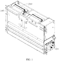
FIG. 1 is a schematic structural view of an air conditioner indoor unit according to an embodiment of the present disclosure. -
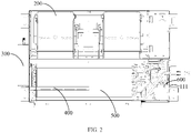
FIG. 2 is an internal schematic structural view ofFIG. 1 . -
FIG. 3 is a left side view ofFIG. 2 . -
FIG. 4 is a right side view ofFIG. 2 . -
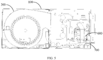
FIG. 5 is a schematic structural view of the air conditioner indoor unit according to another embodiment of the present disclosure. -
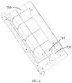
FIG. 6 is a schematic structural view of a water receiving tray of the air conditioner indoor unit of the present disclosure. -
FIG. 7 is a schematic view of a positional relationship between a fan and an indoor heat exchanger of the air conditioner indoor unit according to an embodiment of the present disclosure. -
FIG. 8 is a partial enlarged view of portion A inFIG. 7 . -
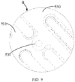
FIG. 9 is a partial enlarged view of portion B inFIG. 7 . -
FIG. 10 is a schematic view of a positional relationship between the fan and the indoor heat exchanger of the air conditioner indoor unit according to another embodiment of the present disclosure. -
FIG. 11 is a schematic structural view of a volute of the air conditioner indoor unit of the present disclosure. -
Table 1 Reference sign Name Reference sign Name 100 housing 110 end plate 111 mounting plate 112 pressing pipe plate 200 fan 210 volute 211 curved surface segment 212 straight surface segment 220 wind wheel 230 motor 250 air outlet 270 fastening plate 300 muffler 400 humidification pipe 500 indoor heat exchanger 510 first heat exchanger 511 first side plate 520 second heat exchanger 521 second side plate 530 connection plate 531 fastening lug 600 siphon device 700 water receiving tray - The realization of the objective, functional characteristics, and advantages of the present disclosure are further described with reference to the accompanying drawings.
- The technical solutions of the embodiments of the present disclosure will be described in more detail below with reference to the accompanying drawings. It is obvious that the embodiments to be described are only some rather than all of the embodiments of the present disclosure. All other embodiments obtained by persons skilled in the art based on the embodiments of the present disclosure without creative efforts shall fall within the scope of the present disclosure.
- It should be noted that if there is a directional indication (such as up, down, left, right, front, rear...) in the embodiments of the present disclosure, the directional indication is only used to explain the relative positional relationship, movement, etc. of the components in a certain posture (as shown in the drawings). If the specific posture changes, the directional indication will change accordingly.
- Besides, the descriptions associated with, e.g., "first" and "second," in the present disclosure are merely for descriptive purposes, and cannot be understood as indicating or suggesting relative importance or impliedly indicating the number of the indicated technical feature. Therefore, the feature associated with "first" or "second" can expressly or impliedly include at least one such feature. The meaning of "and/or" appearing in the disclosure includes three parallel scenarios. For example, "A and/or B" includes only A, or only B, or both A and B. In addition, the technical solutions between the various embodiments can be combined with each other, but they must be based on the realization of those of ordinary skill in the art. When the combination of technical solutions is contradictory or cannot be achieved, it should be considered that such a combination of technical solutions does not exist, nor is it within the scope of the present disclosure.
- The present disclosure provides an air conditioner indoor unit. There are many forms of air conditioner indoor unit, such as wall-mounted air conditioner indoor unit, floor-standing air conditioner indoor unit, or the like. The positional relationship between the air outlet direction of the
volute 210 and theindoor heat exchanger 500 can be adjusted, such that the airflow may extend along the surface of the heat exchanger and pass through the heat exchanger to increase the heat exchanger efficiency of the airflow and the heat exchanger. - The specific structure of the air conditioner indoor unit will be mainly described below.
- As shown in
FIG. 1 to FIG. 11 , in an embodiment of the present disclosure, the air conditioner indoor unit includes: - a
housing 100 provided with an installation cavity; - a
volute 210 installed in the installation cavity, anair outlet 250 of thevolute 210 being inclined towards a bottom of the installation cavity; and - a
first heat exchanger 510 installed in the installation cavity corresponding to the air outlet, thefirst heat exchanger 510 being extended from a bottom of thevolute 210 to a top of thevolute 210, to form an air inlet cavity defined by thevolute 210, thefirst heat exchanger 510 and the bottom of the installation cavity. - Specifically, in this embodiment, the air conditioner indoor unit is described by taking the air conditioner indoor unit with duct as an example. The overall shape of the
housing 100 can have many shapes, such as cuboid-like (on the basis of cuboid, depressions, protrusions, and openings are provided according to actual needs), cylindrical, or the like. Thehousing 100 has an air inlet, an air outlet, and an air duct communicating the air inlet with the air outlet. Both thefan 200 and theindoor heat exchanger 500 are installed in the installation cavity, and in some embodiments, the installation cavity is a part of the air duct. The air conditioner indoor unit includes afirst heat exchanger 510, and in some embodiments, can include both afirst heat exchanger 510 and asecond heat exchanger 520. Thefirst heat exchanger 510 and thesecond heat exchanger 520 are provided in parallel in the refrigerant loop, and can also be provided in series in the refrigerant loop. Regardless of whether thefirst heat exchanger 510 and thesecond heat exchanger 520 are connected in series or in parallel, by setting a reasonable outdoor refrigerant flow path, the working modes of thefirst heat exchanger 510 and thesecond heat exchanger 520 are different or the same. That is, thefirst heat exchanger 510 and thesecond heat exchanger 520 can simultaneously cool and heat; or one can cool and the other one can heat. - The
fan 200 includes avolute 210 and awind wheel 220 provided in thevolute 210, themotor 230 drives thewind wheel 220 to rotate, and a negative pressure area and a positive pressure area are formed in thevolute 210, such that the airflow enters the volute 210 from the air inlet of thevolute 210, and flows out of the volute 210 from theair outlet 250 of thevolute 210. Thevolute 210 includes a curved surface portion and a straight surface portion, both of the curved surface portion and the straight surface portion enclose an accommodating cavity for accommodating thewind wheel 220, and an air outlet duct communicating with the accommodating cavity. The air outlet is located at one end of the air outlet duct away from the accommodating cavity. The direction of the air outlet determines the direction in which the air is discharged from thevolute 210. The direction of the air outlet of thevolute 210 is inclined towards the bottom of the installation cavity, so that the air outlet direction of thevolute 210 is blown out obliquely towards the bottom of the installation cavity. - There are many ways to realize the downward inclination of the
air outlet 250, and an example is given below for description. - The top of the
volute 210 has acurved surface segment 211 and astraight surface segment 212 connected with thecurved surface segment 211, and thestraight surface segment 212 slopes downward relative to a tangent to a top of thecurved surface segment 211. Thus, when the airflow flows out of the air outlet duct, it first flows along thecurved surface segment 211 of thevolute 210, and then flows along thestraight surface segment 212 of thevolute 210, so as to flow downwardly obliquely. Thecurved surface segment 211 is smoothly connected with thestraight surface segment 212, such that the airflow can smoothly flow downwardly obliquely. - The
first heat exchanger 510 is extended from a bottom of thevolute 210 to a top of thevolute 210, such that thefirst heat exchanger 510 is obliquely provided in the installation cavity, and a higher side of thefirst heat exchanger 510 is close to the top of thevolute 210, and a lower side of thefirst heat exchanger 510 is close to the bottom of the installation cavity, and even directly connected to the bottom of the installation cavity. In this way, the airflow blown out from thevolute 210 has a component extending along the air inlet side of thefirst heat exchanger 510, so that the airflow can sufficiently pass through various positions of thefirst heat exchanger 510. An air inlet cavity is formed between the volute 210, thefirst heat exchanger 510, and the bottom of the installation cavity, such that the airflow flowing out of thevolute 210 needs to pass through thefirst heat exchanger 510 before being discharged from the air outlet of the air duct, that is, the airflow needs to exchange heat with thefirst heat exchanger 510. - In this embodiment, the
air outlet 250 of thevolute 210 is inclined towards the bottom of the installation cavity, and the first heat exchanger is inclined along the inclination trend of theair outlet 250 of thevolute 210, such that the airflow out of thevolute 210 has a component that flows along the air inlet side of thefirst heat exchanger 510, the airflow can fill the air inlet side of thefirst heat exchanger 510 and pass through thefirst heat exchanger 510 under the action of the horizontal component of the airflow, and the heat exchange time and heat exchange efficiency between the air and thefirst heat exchanger 510 are greatly improved, which is beneficial to improve the energy efficiency of the air conditioner. Since the air outlet of thevolute 210 is inclined downward, the downward angle of thefirst heat exchanger 510 can be reduced (the angle with the bottom of thehousing 100 is increased). Thus, the installation of thefirst heat exchanger 510 is facilitated (the horizontal distance between the center of gravity of thefirst heat exchanger 510 and the support position of the bottom of thefirst heat exchanger 510 is reduced). The inclination of thefirst heat exchanger 510 is beneficial to increase the heat exchange area of thefirst heat exchanger 510, thereby increasing the heat exchange efficiency. - In some embodiments, in order to ensure that the airflow flows along the air inlet side of the
first heat exchanger 510 and fills thefirst heat exchanger 510, an angle between a direction of theair outlet 250 of thevolute 210 and an inclination direction of thefirst heat exchanger 510 is at least 135° and no more than 150°. Within this angle range, it can be ensured that the airflow blown out from thevolute 210 fills thefirst heat exchanger 510, and a large amount of the airflow will not directly blow the bottom of the installation cavity. When the angle is less than 135°, it is difficult for the airflow out of thevolute 210 to fill the air inlet side of thefirst heat exchanger 510, so that the amount of the air passing through the bottom of thefirst heat exchanger 510 is too small, and the utilization rate of the bottom of thefirst heat exchanger 510 is reduced. When the angle is greater than 150°, the airflow out of thevolute 210 partially flows to the bottom of the air duct, the amount of air passing through the bottom of thefirst heat exchanger 510 is too large, resulting in poor heat exchange effect and at the same time reducing the utilization rate of the upper portion of thefirst heat exchanger 510. - There are many ways to realize that the angle between a direction of the
air outlet 250 of thevolute 210 and the inclination direction of thefirst heat exchanger 510 is at least 135° and no more than 150°. An example is given below for description. - The top of the
volute 210 has acurved surface segment 211 and astraight surface segment 212 connected with thecurved surface segment 211, an angle α between thestraight surface segment 212 and a tangent plane to a top of thecurved surface segment 211 is at least 5° and not more than 10°; and/or an angle β between thefirst heat exchanger 510 and the bottom of the installation cavity is at least 40° and no more than 50°. - The angle between the
straight surface segment 212 and the tangent plane at the top of thecurved surface segment 211 should not be too small. When the angle is less than 5°, thefirst heat exchanger 510 must be deflected by a larger angle in order to satisfy the better heat exchange efficiency, which is not conducive to the installation of thefirst heat exchanger 510, and will also lead to an increase in the width dimension occupied by thefirst heat exchanger 510, and is not conducive to the rational utilization of space. The angle between thestraight surface segment 212 and the tangent plane at the top of thecurved surface segment 211 should not be too large. When the angle is greater than 10°, too many tangent planes at the top of the offsetcurved surface segment 211 are facing the housing, such that when the airflow flows from thecurved surface segment 211 to the straight surface segment, a large deviation will be generated, resulting in excessive pressure loss of the airflow, which is not conducive to the efficient operation of thefan 200. - The angle between the
first heat exchanger 510 and the bottom of the installation cavity should not be too small. When the angle is less than 40°, the lower end of thefirst heat exchanger 510 is far away from the air outlet of thevolute 210, which is unfavorable for the airflow in thevolute 210 to flow to the bottom of the air inlet side of thefirst heat exchanger 510, will reduce the utilization rate of the bottom of thefirst heat exchanger 510, and is not conducive to the installation of thefirst heat exchanger 510, and will also lead to an increase in the width dimension occupied by thefirst heat exchanger 510, which is not conducive to the rational utilization of space. The angle between thefirst heat exchanger 510 and the bottom of the installation cavity should not be too large. When the angle is greater than 50°, the heat exchange area of thefirst heat exchanger 510 will be reduced, and at the same time, the time for flowing out of thevolute 210 and passing through the upper portion of thefirst heat exchanger 510 will be shortened, which is not conducive to the heat exchange between the airflow and thefirst heat exchanger 510. - The air conditioner indoor unit further includes a
second heat exchanger 520. Thesecond heat exchanger 520 is connected in series or in parallel with thefirst heat exchanger 510 in a refrigerant loop of an air conditioner, and thesecond heat exchanger 520 is located on a side of thefirst heat exchanger 510 away from thevolute 210. When thefirst heat exchanger 510 is cooling and thesecond heat exchanger 520 is heating, the air conditioner indoor unit can realize dehumidification and reheating, and can dehumidify the air without affecting the use of users by temperature changes. Thesecond heat exchanger 520 is provided on the side of thefirst heat exchanger 510 facing away from thevolute 210, so that the airflow is dehumidified first and then heated, which is beneficial to improve the dehumidification efficiency. An angle between thesecond heat exchanger 520 and the bottom of thehousing 100 is γ, and γ is taken as an example of being 90 degrees. - In some embodiments, in order to improve the compactness of the structure of the air conditioner indoor unit, the
second heat exchanger 520 is provided vertically. In this way, on the premise of ensuring the heat exchange efficiency, the arrangement among thefan 200, thefirst heat exchanger 510 and thesecond heat exchanger 520 is very compact, which is beneficial to improve the space utilization rate of the indoor unit. - In some embodiments, in order to further improve the convenience and stability of the installation of the
first heat exchanger 510 and thesecond heat exchanger 520, the air conditioner indoor unit further includes aconnection plate 530, one side of theconnection plate 530 is fixedly connected with afirst side plate 511 of thefirst heat exchanger 510, and another side of theconnection plate 530 is fixedly connected with a second side plate of 521 thesecond heat exchanger 520. - In this embodiment, the
first heat exchanger 510 includes a first refrigerant pipe and afirst side plate 511 connected to the first refrigerant pipe, and thesecond heat exchanger 520 includes a second refrigerant pipe and asecond side plate 521 connected to the second refrigerant pipe. The first side of the connectingplate 530 is fixedly connected to thefirst side plate 511, and the second side of the connectingplate 530 is fixedly connected to thesecond side plate 521. The number of theconnection plates 530 is two, which are respectively provided on both end surfaces of thefirst heat exchanger 510 and thesecond heat exchanger 520 and correspond to thefirst side plate 511 and thesecond side plate 521 respectively. Thefirst heat exchanger 510, thesecond heat exchanger 520 and theconnection plate 530 can form a module, and the three can be assembled first and then installed into thehousing 100. As such, since the operable space has been greatly increased, it is not only beneficial to greatly improve the installation efficiency of the three, and connecting thefirst heat exchanger 510 and thesecond heat exchanger 520 through the mountingplate 111 can also effectively ensure the relative positional relationship (angle) between thefirst heat exchanger 510 and thesecond heat exchanger 520. When thesecond heat exchanger 520 is set to be vertical, it is very simple and convenient to ensure the off-angle of thefirst heat exchanger 510 relative to the bottom of thehousing 100, therefore, it is beneficial to improve the installation accuracy of thefirst heat exchanger 510 and ensure the heat exchange effect of the heat exchanger. - There are many ways to fix the
connection plate 530 and thefirst side plate 511 and thesecond side plate 521. In order to make full use of space and improve connection reliability, theconnection plate 530 is in parallel with thefirst side plate 511 and thesecond side plate 521, thefirst side plate 511 and thesecond side plate 521 are provided with installation holes for installing a refrigerant pipe, fastening lugs 531 are respectively provided on adjacent or opposite sides of theconnection plate 530, and the fastening lugs 531 are extended between two adjacent installation holes and are fastened to the corresponding side plates through fasteners. - In this embodiment, the fastening lugs 531 are provided on the first side and the second side of the
connection plate 530. The U-shaped refrigerant pipe is connected to the straight refrigerant pipe, and there is a gap for the fastening lugs 531 to be installed between two adjacent U-shaped pipes. The fastening lugs 531 are attached to thefirst side plate 511 or thesecond side plate 521, and the two are connected by fastening screws, bolts, or buckles. In this way, the reliability and installation accuracy between thefirst side plate 511, thesecond side plate 521 and theconnection plate 530 are greatly improved. - It should be noted that, in some embodiments, in order to ensure the relative positional relationship between the
volute 210 and the first heat exchanger, the indoor unit further includes afastening plate 270, the air outlet end of thevolute 210 is mounted on thefastening plate 270, and thefastening plate 270 is fixedly connected with the housing. Thefastening plate 270 has a fastening opening for the air outlet end of thevolute 210 to be installed. Through the arrangement of thefastening plate 270, the installation accuracy of thevolute 210 is guaranteed, thereby helping to ensure the relative positional relationship between thevolute 210 and thefirst heat exchanger 510. - In some embodiments, in order to further improve the installation stability of the
first heat exchanger 510 and thesecond heat exchanger 520, one or more among theconnection plate 530, thefirst side plate 511 and thesecond side plate 521 are fixedly connected to the end of thehousing 100. One or more among theconnection plate 530, thefirst side plate 511, and thesecond side plate 521 are fastened to theend plate 110 of thehousing 100, and the fastening method includes screw connection, snap connection, and the like. Theend plate 110 of thehousing 100 corresponding to theconnection plate 530, thefirst side plate 511 and thesecond side plate 521 is apressing pipe plate 112, and thepressing pipe plate 112 is a part of thehousing 100. In some embodiments, thepressing pipe plate 112 can be a fastening plate independent from thehousing 100. - A bottom of the
first heat exchanger 510 and/or a bottom of thesecond heat exchanger 520 is fixedly connected to a bottom of the housing. There are many ways for thefirst heat exchanger 510 and thesecond heat exchanger 520 to be fixedly connected to the bottom of the housing, such as fastened connection by screws, fixed connection by snaps, and so on. In some embodiments, the air conditioner indoor unit further includes awater receiving tray 700 located directly below thefirst heat exchanger 510, and thewater receiving tray 700 is fixedly connected to the bottom of the housing. At this time, the bottom of thefirst heat exchanger 510 can be connected to thewater receiving tray 700. - In some embodiments, in order to allow the air conditioner indoor unit to quietly humidify the air, the air conditioner indoor unit includes:
- a
housing 100 defined with an air inlet, an air outlet, and an air duct communicating the air inlet with the air outlet; - a humidification assembly including a steam generating device and a
humidification pipe 400, one end of thehumidification pipe 400 away from the steam generating device extending into the air duct; and - a
muffler 300 provided between the steam generating device and thehumidification pipe 400, or provided on thehumidification pipe 400. - Specifically, in this embodiment, there are many forms of steam generating devices, for example, water can be changed into steam by ultrasonic. A steam generator can also be provided. The steam generator has a steam cavity. A heating element is provided in the steam cavity, and when the temperature of the heating element reaches a preset temperature, water is injected into the heating element, so that the water forms high-pressure water vapor. The heating pipe can be in many forms, and can be a soft pipe or a rigid pipe, and a number of humidification holes are defined on the pipe wall of the
humidification pipe 400. After being vaporized or atomized by the steam generating device, the water vapor is guided through thehumidification pipe 400, flows out from the humidification hole, enters the air duct, and is finally discharged into the room together with the airflow. No matter what kind of humidification method, it will bring certain noise. In this case, in order not to affect the use of the user, themuffler 300 is installed on the transmission path of the steam to avoid the spread and diffusion of noise. - Taking the
muffler 300 provided between the steam generating device and thehumidification pipe 400 as an example. The water inlet end of the steam generating device obtains liquid water. After the liquid water is converted into water vapor through the steam generating device, it passes through themuffler 300, and the air inlet end of thehumidification pipe 400 is communicated with themuffler 300, so that the steam enters the air duct through thehumidification pipe 400. There are many forms of themuffler 300, taking the muffler pipe as an example. After the steam flows out of the steam generating device, it enters thehumidification pipe 400 through the muffler pipe. - In this embodiment, the steam generating device and the
muffler 300 are provided, such that the steam flowing out of the steam generating device, after passing through themuffler 300, enters thehumidification pipe 400, and enters thehousing 100 through thehumidification pipe 400. After the steam flows out of the humidification hole, it enters the air duct, and then enters the room together with the airflow to humidify the room. During this process, themuffler 300 reduces the noise generated by the generation and transmission of steam, so that the air conditioner can humidify the air quietly. - In some embodiments, in order to prevent steam or water droplets (formed by steam condensation) from flowing back into the
muffler 300 or the steam generating device, thehumidification pipe 400 extends along the length direction of thehousing 100, and one end away from themuffler 300 is inclined toward the bottom of thehousing 100. In this way, the water droplets can only flow along thehumidification pipe 400 in a direction away from themuffler 300, and finally flow out from thehumidification pipe 400, enter thewater receiving tray 700, or flow out of the air conditioner, to avoid backflow of water vapor or water droplets in thehumidification pipe 400 to themuffler 300 and the steam generating device. - In order to further prevent backflow, the
muffler 300 extends along the length direction or the width direction of thehousing 100, and is inclined towards the bottom of thehousing 100 near one end of thehumidification pipe 400. Themuffler 300 can extend along the length direction of thehousing 100 or can extend along the width direction of thehousing 100. One end of themuffler 300 connected to thehumidification pipe 400 is lower than the end of themuffler 300 connected to the steam generating device, such that the steam or water droplets will not flow back into the steam generating device, and water will not be collected in the steam pipeline to avoid the growth of bacteria, which is beneficial to the user's healthy when using the air conditioner. - In order to improve the convenience of installation and removal of the
muffler 300 and thehumidification pipe 400, themuffler 300 is fixedly connected to the outer side wall of one end of thehousing 100. Themuffler 300 is provided outside thehousing 100, so that the installation and removal of themuffler 300 is very convenient. Thehumidification pipe 400 extends out of thehousing 100 and is connected to themuffler 300. There are many ways to connect thehumidification pipe 400 and themuffler 300, such as plug connection, connection through a fastening sleeve, and the like. Since the connection position of thehumidification pipe 400 and themuffler 300 is located outside thehousing 100, the installation and removal of thehumidification pipe 400 are very convenient. - In some embodiments, in order to improve the space utilization rate and the compactness of the structure, and improve the convenience of assembling and disassembling the
muffler 300, the steam generating device is installed inside thehousing 100, and the exhaust pipe of the steam generating device extends out of thehousing 100 and is connected to the end of themuffler 300 away from thehumidification pipe 400. The connection position of themuffler 300 and the steam generating device is provided outside thehousing 100, and themuffler 300 and the steam generating device can be separated without opening thehousing 100. - In some embodiments, in order to improve the adaptability and capability integrity of the air conditioner indoor unit, the air conditioner indoor unit further includes a siphon
device 600, the drain end of the siphondevice 600 is communicated with the steam generating device through a drain pipe, and the water inlet end of the siphondevice 600 is used to communicate with the water source. The siphondevice 600 is used for conveying water to the steam generating device, and can be in various forms, such as a water pump and the like. With the arrangement of the siphondevice 600, the air conditioner indoor unit has the ability to release water for the steam generating device, so as to supply water to the steam generating device of the air conditioner indoor unit without relying on external equipment, such that the air conditioner indoor unit can humidify the air in more occasions. - There can be many forms of water sources, an additional water tank can be provided, water can also be absorbed from the outside, and the water in the
water receiving tray 700 can also be collected by the air conditioner indoor unit. The air conditioner indoor unit further includes awater receiving tray 700, and thewater receiving tray 700 has a drain end. The siphondevice 600 is disposed near the drain end of thewater receiving tray 700, and the water inlet end of the siphondevice 600 communicates with thewater receiving tray 700. The overall shape of thewater receiving tray 700 can be various, taking a rectangular tray as an example, thewater receiving tray 700 is provided below theindoor heat exchanger 500 to receive the condensed water generated in the refrigeration process and the dehumidification and reheating process. One end of thewater receiving tray 700 is provided with a drain pipe communicating thewater receiving tray 700 and the outside of thewater receiving tray 700. The siphondevice 600 can be communicated with thewater receiving tray 700 through a pipeline, or the water inlet end of the siphondevice 600 can be directly provided in thewater receiving tray 700, such that the siphondevice 600 can absorb the water in thewater receiving tray 700 and deliver the water to the steam generating device. In this way, it is beneficial to make full use of the existing structure and resources (the water receiving tray 700), and humidification can be performed without installing a water tank, which greatly simplifies the structure of the air conditioner indoor unit. - When using the water in the
water receiving tray 700 for humidification, in order to prevent the siphondevice 600 from being unloaded, when the water volume in thewater receiving tray 700 is insufficient, the user is promptly reminded to turn off the siphondevice 600. - The air conditioner indoor unit further includes a water level switch. The water level switch is provided near the siphon
device 600, and the water inlet end of the siphondevice 600 and the water level switch are located in thewater receiving tray 700. The water level switch is electrically connected with the siphondevice 600, and the water level switch is used to detect the water level in thewater receiving tray 700. When the water level in thewater receiving tray 700 is low enough to supply the siphondevice 600, the water level switch can directly close the siphondevice 600, or send the detected information to the main control circuit of the air conditioner, and the main control circuit controls the siphondevice 600 to stop working. The water level switch can directly trigger the prompting device to work to prompt the user that there is a lack of water. The prompting device may be one or more of a sound prompting device, a light prompting device, a vibration prompting device and a short message prompting. - The drain end of the
water receiving tray 700 is provided with a first installation position for installing the water level switch, and a second installation position for installing the water inlet end of the siphondevice 600. The first installation position and the second installation position are grooves recessed towards the bottom of thewater receiving tray 700, so that the water in thewater receiving tray 700 can flow into the first installation position and the second installation position. The first installation position is located upstream of the second installation position, so that the water first flows through the water level switch and then into the siphondevice 600, the water level switch can timely control the siphondevice 600 according to the detection result, so as to minimize the unloading of the siphondevice 600, which is beneficial to protect the siphondevice 600. - In some embodiments, in order to improve the convenience of installation and removal of the siphon
device 600, one end of thehousing 100 has a mountingplate 111, the mountingplate 111 is a part of thehousing 100, and the siphondevice 600 is mounted on the mountingplate 111. The mountingplate 111 on which the siphondevice 600 is installed is used as a part of thehousing 100, and the siphondevice 600 can be installed and removed without opening thehousing 100 during the disassembly process. Specifically, the mountingplate 111 and the rest of thehousing 100 can be connected by means of screws, snaps, and the like. When disassembling the siphondevice 600, the cooperation between the mountingplate 111 and thehousing 100 can be disengaged, and the mountingplate 111 and the siphondevice 600 can be taken out together. When installing the siphondevice 600, the mountingplate 111 and the siphondevice 600 can be inserted into thehousing 100 together, and the mountingplate 111 and the rest of thehousing 100 can be fastened. In this way, the disassembly and installation of the siphondevice 600 is facilitated. - In some embodiments, in order to improve the installation stability of the heat exchanger and the installation stability of the siphon
device 600, one end of thehousing 100 also has apressing pipe plate 112, and thepressing pipe plate 112 is provided corresponding to one end of theindoor heat exchanger 500 of the air conditioner indoor unit. Thepressing pipe plate 112 and the mountingplate 111 are spliced together to form part of theend plate 110 of thehousing 100. As a part of theend plate 110 of thehousing 100, thepressing pipe plate 112 extrudes the U-shaped refrigerant pipe, or is connected with the side plate of theindoor heat exchanger 500, and is used for installing and fixing theindoor heat exchanger 500. Thepressing pipe plate 112 and the mountingplate 111 are connected by means of screws, buckles, etc., so that the mountingplate 111 and thepressing pipe plate 112 are mutually limited and fixed, and the installation stability of the two is improved. - In some embodiments, in order to make the space of the
housing 100 more reasonable and improve the compactness of the structure, the siphondevice 600 and themuffler 300 are located at opposite ends of thehousing 100 respectively. In this way, the siphon water source and atomization, noise reduction and humidification are located at opposite ends of thehousing 100, which is beneficial for the above-mentioned devices to be installed in the gaps between thehousing 100 and the heat exchanger, and between thehousing 100 and thewind wheel 220, therefore the space inside and outside thehousing 100 is fully utilized, which is beneficial to improve the utilization rate of the space. The siphondevice 600 communicates with the steam generating device through a hose to expose the water source. - It should be noted that in some embodiments, the siphon
device 600, the humidification assembly and themuffler 300 can be regarded as an integral module, which can be set as an optional configuration. When the user needs, the siphondevice 600, the humidification assembly and themuffler 300 can be easily added to thehousing 100 or inside thehousing 100 due to the convenience of disassembly of the humidification assembly, themuffler 300 and the siphondevice 600. In this way, the functions of the air conditioner indoor unit can be adjusted according to the needs of different users, so as to meet the needs of different users, which is beneficial to improve the adaptability of the air conditioner indoor unit. - The present disclosure further provides an air conditioner, including an outdoor unit and an air conditioner indoor unit. The specific structure of the air conditioner indoor unit refers to the above-mentioned embodiment. Since the air conditioner adopts all the technical solutions of all the above-mentioned embodiments, it has at least all the beneficial effects brought by the technical solutions of the above-mentioned embodiments, and will not be repeated herein. The outdoor unit and the indoor unit are connected through a refrigerant pipe to form a refrigerant circulation system.
- The above are only some embodiments of the present disclosure, and do not limit the scope of the present disclosure thereto. Under the inventive concept of the present disclosure, equivalent structural transformations made according to the description and drawings of the present disclosure, or direct/indirect application in other related technical fields are included in the scope of the present disclosure.
Claims (13)
- An air conditioner indoor unit, comprising:a housing provided with an installation cavity;a volute installed in the installation cavity, an air outlet of the volute being inclined towards a bottom of the installation cavity; anda first heat exchanger installed in the installation cavity corresponding to the air outlet, the first heat exchanger being extended from a bottom of the volute to a top of the volute, to form an air inlet cavity enclosed by the volute, the first heat exchanger and the bottom of the installation cavity.
- The air conditioner indoor unit of claim 1, wherein the top of the volute has a curved surface segment and a straight surface segment connected with the curved surface segment, wherein the straight surface segment is sloped downward relative to a tangent plane to a top of the curved surface segment.
- The air conditioner indoor unit of claim 2, wherein the curved surface segment is smoothly connected with the straight surface segment.
- The air conditioner indoor unit of claim 1, wherein an angle between a direction of the air outlet of the volute and an inclination direction of the first heat exchanger is at least 135° and no more than 150°.
- The air conditioner indoor unit of claim 4, wherein the top of the volute has a curved surface segment and a straight surface segment connected with the curved surface segment, an angle between the straight surface segment and a tangent plane to a top of the curved surface segment is at least 5° and not more than 10°; and/or
an angle between the first heat exchanger and the bottom of the installation cavity is at least 40° and no more than 50°. - The air conditioner indoor unit of claim 1, further comprising:a second heat exchanger;wherein the second heat exchanger is connected in series or in parallel with the first heat exchanger in a refrigerant loop for an air conditioner, and the second heat exchanger is located on a side of the first heat exchanger facing away from the volute.
- The air conditioner indoor unit of claim 6, wherein the second heat exchanger is vertically provided.
- The air conditioner indoor unit of claim 6, further comprising:a connection plate;wherein a side of the connection plate is fixedly connected with a first side plate of the first heat exchanger, and an other side of the connection plate is fixedly connected with a second side plate of the second heat exchanger.
- The air conditioner indoor unit of claim 8, wherein the connection plate is in parallel with the first side plate and the second side plate, the first side plate and the second side plate are provided with installation holes for installing a refrigerant pipe, fastening lugs are respectively provided on adjacent or opposite sides of the connection plate, and the fastening lugs are extended between two adjacent installation holes and are fastened to corresponding side plates through fasteners.
- The air conditioner indoor unit of claim 8, wherein one or more among the connection plate, the first side plate and the second side plate are fixedly connected to an end of the housing.
- The air conditioner indoor unit of claim 6, wherein a bottom of the first heat exchanger and/or a bottom of the second heat exchanger is fixedly connected to a bottom of the housing.
- The air conditioner indoor unit of claim 1, further comprising:a fastening plate,wherein the air outlet of the volute is mounted on the fastening plate, and the fastening plate is fixedly connected with the housing.
- An air conditioner, comprising:an air conditioner indoor unit of claim 1; andan outdoor unit communicated with the air conditioner indoor unit through a refrigerant pipe.
Applications Claiming Priority (3)
| Application Number | Priority Date | Filing Date | Title |
|---|---|---|---|
| CN201911057167.0A CN112747375A (en) | 2019-10-30 | 2019-10-30 | Indoor unit of air conditioner |
| CN201921852128.5U CN210801406U (en) | 2019-10-30 | 2019-10-30 | Air conditioner indoor unit |
| PCT/CN2020/078834 WO2021082328A1 (en) | 2019-10-30 | 2020-03-11 | Air conditioner indoor unit and air conditioner |
Publications (2)
| Publication Number | Publication Date |
|---|---|
| EP4012274A1 true EP4012274A1 (en) | 2022-06-15 |
| EP4012274A4 EP4012274A4 (en) | 2022-09-28 |
Family
ID=75715548
Family Applications (1)
| Application Number | Title | Priority Date | Filing Date |
|---|---|---|---|
| EP20882223.9A Pending EP4012274A4 (en) | 2019-10-30 | 2020-03-11 | AIR CONDITIONER AND AIR CONDITIONER INDOOR UNIT |
Country Status (3)
| Country | Link |
|---|---|
| US (1) | US11808464B2 (en) |
| EP (1) | EP4012274A4 (en) |
| WO (1) | WO2021082328A1 (en) |
Families Citing this family (1)
| Publication number | Priority date | Publication date | Assignee | Title |
|---|---|---|---|---|
| CN115654583B (en) * | 2022-10-13 | 2025-03-21 | 青岛海尔空调器有限总公司 | Air conditioner indoor unit |
Family Cites Families (17)
| Publication number | Priority date | Publication date | Assignee | Title |
|---|---|---|---|---|
| KR20080001311A (en) * | 2006-06-29 | 2008-01-03 | 주식회사 대우일렉트로닉스 | Air conditioner with multi-stage evaporator |
| CN201377863Y (en) * | 2009-02-25 | 2010-01-06 | 滁州扬子必威中央空调有限公司 | Fan coil unit with double rows of pipes and big enthalpy difference |
| JP5587060B2 (en) * | 2010-06-30 | 2014-09-10 | 三洋電機株式会社 | Built-in air conditioner |
| CN202452604U (en) * | 2012-02-29 | 2012-09-26 | 青岛海尔空调电子有限公司 | Indoor unit of duct type air conditioner |
| CN103267341B (en) * | 2013-05-31 | 2015-07-29 | 青岛海尔空调电子有限公司 | A kind of air nozzle structure and air-cooled ducted air conditioner |
| CN105066251A (en) * | 2015-08-10 | 2015-11-18 | 珠海格力电器股份有限公司 | Air duct machine |
| CN106839086B (en) * | 2015-11-27 | 2019-12-17 | 青岛海尔空调电子有限公司 | A fan coil unit |
| JP6717003B2 (en) | 2016-03-31 | 2020-07-01 | 東ソー株式会社 | Wavelength dispersion adjusting agent, resin composition containing the same, and optical film using the resin composition |
| WO2017179191A1 (en) * | 2016-04-15 | 2017-10-19 | 三菱電機株式会社 | Air conditioning indoor unit |
| US10865798B2 (en) * | 2016-05-30 | 2020-12-15 | Zhongshan Broad-Ocean Motor Co., Ltd. | Fan coil unit |
| CN106523434B (en) * | 2016-11-23 | 2020-02-28 | 青岛海尔空调电子有限公司 | A centrifugal fan volute and indoor unit |
| CN108489156A (en) * | 2018-03-26 | 2018-09-04 | 海信(山东)空调有限公司 | A kind of evaporator assemblies and its installation method, air-cooled ducted air conditioner |
| CN108758811B (en) * | 2018-06-05 | 2024-06-18 | 广东美的暖通设备有限公司 | Three-pipe duct type indoor unit and duct type air conditioner |
| CN208620440U (en) * | 2018-07-28 | 2019-03-19 | 宁波奥克斯电气股份有限公司 | A kind of air-cooled ducted air conditioner |
| CN209042572U (en) * | 2018-07-28 | 2019-06-28 | 宁波奥克斯电气股份有限公司 | a duct machine |
| CN109237625A (en) * | 2018-07-28 | 2019-01-18 | 宁波奥克斯电气股份有限公司 | A kind of air-cooled ducted air conditioner |
| CN109974115A (en) * | 2019-04-08 | 2019-07-05 | 广东美的暖通设备有限公司 | Air conditioner indoor unit and air conditioner |
-
2020
- 2020-03-11 WO PCT/CN2020/078834 patent/WO2021082328A1/en not_active Ceased
- 2020-03-11 EP EP20882223.9A patent/EP4012274A4/en active Pending
-
2022
- 2022-03-25 US US17/704,233 patent/US11808464B2/en active Active
Also Published As
| Publication number | Publication date |
|---|---|
| US11808464B2 (en) | 2023-11-07 |
| EP4012274A4 (en) | 2022-09-28 |
| WO2021082328A1 (en) | 2021-05-06 |
| US20220214051A1 (en) | 2022-07-07 |
Similar Documents
| Publication | Publication Date | Title |
|---|---|---|
| CN201571292U (en) | Active heat radiation type cabinet | |
| CN109842276A (en) | Frequency converter and air conditioner | |
| CN205079379U (en) | Computer lab air conditioner | |
| CN203467116U (en) | Cabinet air-conditioning system | |
| US11808464B2 (en) | Air conditioner indoor unit and air conditioner | |
| CN210801406U (en) | Air conditioner indoor unit | |
| CN210832220U (en) | Air conditioner indoor unit | |
| WO2020233621A1 (en) | Refrigeration cycle apparatus | |
| CN207094818U (en) | Wall-hanging air conditioner indoor unit and air conditioner | |
| CN215062476U (en) | Humidifiers and Air Conditioning Systems | |
| CN221881632U (en) | Indoor machine of vertical air conditioner | |
| CN210118873U (en) | Air conditioner indoor unit and air conditioner | |
| CN206755412U (en) | Automatically controlled radiator structure and air-conditioning equipment | |
| CN209801630U (en) | Air duct machine | |
| CN214949372U (en) | Humidification device and air conditioning system with same | |
| CN112747362B (en) | Air conditioner indoor unit | |
| CN210425295U (en) | Window air conditioner | |
| CN109974114A (en) | Air conditioner humidifier, air conditioner humidifier drip tray mounting structure and air conditioner | |
| CN209857223U (en) | Air conditioner humidifier, mounting structure of water collector of air conditioner humidifier and air conditioner | |
| CN117190323A (en) | Air conditioner | |
| CN112747375A (en) | Indoor unit of air conditioner | |
| CN207471729U (en) | Modular air conditioner | |
| CN207688306U (en) | Dehumidifier | |
| CN221375831U (en) | Air conditioner outdoor unit and air conditioner with same | |
| CN207422448U (en) | The hanging air conditioner that can fast assemble |
Legal Events
| Date | Code | Title | Description |
|---|---|---|---|
| STAA | Information on the status of an ep patent application or granted ep patent |
Free format text: STATUS: THE INTERNATIONAL PUBLICATION HAS BEEN MADE |
|
| PUAI | Public reference made under article 153(3) epc to a published international application that has entered the european phase |
Free format text: ORIGINAL CODE: 0009012 |
|
| STAA | Information on the status of an ep patent application or granted ep patent |
Free format text: STATUS: REQUEST FOR EXAMINATION WAS MADE |
|
| 17P | Request for examination filed |
Effective date: 20220310 |
|
| AK | Designated contracting states |
Kind code of ref document: A1 Designated state(s): AL AT BE BG CH CY CZ DE DK EE ES FI FR GB GR HR HU IE IS IT LI LT LU LV MC MK MT NL NO PL PT RO RS SE SI SK SM TR |
|
| A4 | Supplementary search report drawn up and despatched |
Effective date: 20220831 |
|
| RIC1 | Information provided on ipc code assigned before grant |
Ipc: F24F 1/0018 20190101ALI20220825BHEP Ipc: F24F 1/0025 20190101ALI20220825BHEP Ipc: F24F 1/0011 20190101ALI20220825BHEP Ipc: F24F 1/0063 20190101AFI20220825BHEP |
|
| DAV | Request for validation of the european patent (deleted) | ||
| DAX | Request for extension of the european patent (deleted) | ||
| STAA | Information on the status of an ep patent application or granted ep patent |
Free format text: STATUS: EXAMINATION IS IN PROGRESS |
|
| 17Q | First examination report despatched |
Effective date: 20240606 |