EP4012232A1 - Scraper ring for a piston - Google Patents
Scraper ring for a piston Download PDFInfo
- Publication number
- EP4012232A1 EP4012232A1 EP21209155.7A EP21209155A EP4012232A1 EP 4012232 A1 EP4012232 A1 EP 4012232A1 EP 21209155 A EP21209155 A EP 21209155A EP 4012232 A1 EP4012232 A1 EP 4012232A1
- Authority
- EP
- European Patent Office
- Prior art keywords
- scraper ring
- projection
- contact
- approximately
- extends
- Prior art date
- Legal status (The legal status is an assumption and is not a legal conclusion. Google has not performed a legal analysis and makes no representation as to the accuracy of the status listed.)
- Pending
Links
- 238000002485 combustion reaction Methods 0.000 claims abstract description 23
- 239000012530 fluid Substances 0.000 claims description 12
- 239000000446 fuel Substances 0.000 description 18
- 230000006835 compression Effects 0.000 description 8
- 238000007906 compression Methods 0.000 description 8
- 239000000203 mixture Substances 0.000 description 7
- 239000000463 material Substances 0.000 description 3
- 230000001419 dependent effect Effects 0.000 description 2
- 239000000126 substance Substances 0.000 description 2
- 239000011324 bead Substances 0.000 description 1
- 230000009286 beneficial effect Effects 0.000 description 1
- 230000003247 decreasing effect Effects 0.000 description 1
- 239000002283 diesel fuel Substances 0.000 description 1
- 238000004880 explosion Methods 0.000 description 1
- 230000013011 mating Effects 0.000 description 1
- 238000012986 modification Methods 0.000 description 1
- 230000004048 modification Effects 0.000 description 1
- 238000007789 sealing Methods 0.000 description 1
- 229910001220 stainless steel Inorganic materials 0.000 description 1
- 239000010935 stainless steel Substances 0.000 description 1
- 238000013022 venting Methods 0.000 description 1
Images


Classifications
-
- F—MECHANICAL ENGINEERING; LIGHTING; HEATING; WEAPONS; BLASTING
- F16—ENGINEERING ELEMENTS AND UNITS; GENERAL MEASURES FOR PRODUCING AND MAINTAINING EFFECTIVE FUNCTIONING OF MACHINES OR INSTALLATIONS; THERMAL INSULATION IN GENERAL
- F16J—PISTONS; CYLINDERS; SEALINGS
- F16J9/00—Piston-rings, e.g. non-metallic piston-rings, seats therefor; Ring sealings of similar construction
- F16J9/12—Details
- F16J9/20—Rings with special cross-section; Oil-scraping rings
- F16J9/206—One-piece oil-scraping rings
-
- F—MECHANICAL ENGINEERING; LIGHTING; HEATING; WEAPONS; BLASTING
- F16—ENGINEERING ELEMENTS AND UNITS; GENERAL MEASURES FOR PRODUCING AND MAINTAINING EFFECTIVE FUNCTIONING OF MACHINES OR INSTALLATIONS; THERMAL INSULATION IN GENERAL
- F16J—PISTONS; CYLINDERS; SEALINGS
- F16J9/00—Piston-rings, e.g. non-metallic piston-rings, seats therefor; Ring sealings of similar construction
- F16J9/12—Details
- F16J9/14—Joint-closures
-
- F—MECHANICAL ENGINEERING; LIGHTING; HEATING; WEAPONS; BLASTING
- F16—ENGINEERING ELEMENTS AND UNITS; GENERAL MEASURES FOR PRODUCING AND MAINTAINING EFFECTIVE FUNCTIONING OF MACHINES OR INSTALLATIONS; THERMAL INSULATION IN GENERAL
- F16J—PISTONS; CYLINDERS; SEALINGS
- F16J9/00—Piston-rings, e.g. non-metallic piston-rings, seats therefor; Ring sealings of similar construction
- F16J9/26—Piston-rings, e.g. non-metallic piston-rings, seats therefor; Ring sealings of similar construction characterised by the use of particular materials
Definitions
- the present disclosure relates generally to a piston ring and, for example, to a scraper ring for a piston.
- a power system powers a machine by converting chemical energy stored in fuel (e.g., diesel fuel, gasoline, and/or the like) into mechanical work.
- fuel e.g., diesel fuel, gasoline, and/or the like
- an air-fuel mixture is either formed in a combustion chamber of a cylinder or introduced into the combustion chamber of the cylinder.
- a piston is mounted within the cylinder to slide along a lubricated surface in a cycle between a top dead center (TDC) position and a bottom dead center (BDC) position.
- TDC top dead center
- BDC bottom dead center
- a force of the explosion drives the piston down towards the BDC position, and the cycle repeats. Because the piston is connected to a drivetrain of the machine, continued movement of the piston propels and/or powers the machine.
- the piston In order to substantially seal the combustion chamber (e.g., to substantially limit the air-fuel mixture from leaking out of the combustion chamber and/or to substantially limit oil on the lubricated surface from entering the combustion chamber), the piston includes expandable rings mounted to an outer surface thereof. However, because the expandable rings have end gaps, the expandable rings may permit a bead of the oil to flow directly into the combustion chamber. As a result, the power system may experience performance issues, such as increased oil consumption, surface deposits, emissions, and/or unintentional ignition of the charge.
- U.S. Publication No. 2012/0112415 which published on May 10, 2012 , discloses a rotating seal ring (or piston ring).
- the seal ring is split to define a first free end (or arm) and a second free end (or arm) that can contact overlap one another, and which can move relative to another in a circumferential direction along a split surface located at an interface between mating cut-out notch surfaces of the first and second free ends.
- the scraper ring of the present disclosure solves one or more of the problems set forth above and/or other problems in the art.
- a scraper ring for a piston includes an arcuate body comprising an inner surface, an outer surface, a first end surface connecting the inner surface to the outer surface, and a second end surface that is opposite to the first end surface, a first projection extending circumferentially from the first end surface, wherein the first projection comprises a first inner surface, a first outer surface, and a first contact surface connecting the first inner surface to the first outer surface; and a second projection extending circumferentially from the second end surface, wherein the second projection comprises a second inner surface, a second outer surface, and a second contact surface connecting the second inner surface to the second outer surface; wherein the first contact surface is configured to slidably contact the second contact surface to adjust a diameter of the scraper ring; and wherein, when the first contact surface contacts the second contact surface, the inner surface, the first inner surface, and the second inner surface together define an interior surface of the scraper ring that extends 360 degrees relative to a central axis of the scraper ring, and the
- a scraper ring for a piston includes a top surface having a first planar portion and a first angled portion; a bottom surface having a second planar portion and a second angled portion, wherein the second angled portion is configured to slidably contact the first angled portion to adjust a diameter of the scraper ring; an inner surface connecting the top surface to the bottom surface; and an outer surface that is opposite to the top surface, wherein the outer surface is configured to form 360 degrees of contact with a wall of a cylinder to substantially limit an amount of oil entering a combustion chamber of the cylinder.
- a scraper ring includes an outer surface that is configured to form 360 degrees of contact with a wall of a cylinder in order to substantially limit oil from passing between the scraper ring and the wall to enter a combustion chamber of the cylinder; and a bottom surface that is configured to form less than 360 degrees of contact with a land of a piston to permit gas to vent between the scraper ring and the land.
- a ring which is applicable to any system that includes a movable junction between two chambers of fluid.
- the system may be a power system
- the movable junction may be a piston that separates a combustion chamber of a cylinder from an interior of a crankcase.
- the combustion chamber may contain an air-fuel mixture, while the interior of the crankcase may contain oil.
- the power system may be implemented in a vehicle (e.g., a motor vehicle, a railed vehicle, a watercraft, an aircraft), a generator, or another machine.
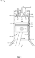
- Figs. 1-2 depict an exemplary power system 100.
- the power system 100 includes a cylinder 102, an intake valve 104, a fuel injector 106, an exhaust valve 108, a piston assembly 110, and a crankcase 112.
- the cylinder 102 includes an upper end 114, a lower end 116, and a wall 118 extending between the upper end 114 and the lower end 116.
- the upper end 114 of the cylinder 102 includes an air inlet 120, a fuel inlet 122, and an exhaust outlet 124.
- the intake valve 104 is movably seated in the air inlet 120 to allow air to pass therethrough into the cylinder 102.
- the fuel injector 106 is mounted to the fuel inlet 122 to allow fuel to pass therethrough into the cylinder 102 to mix with the air to form an air-fuel mixture.
- the exhaust valve 108 is movably seated in the exhaust outlet 124 to allow exhaust gas to pass therethrough to exit the cylinder 102.
- the lower end 116 of the cylinder 102 is connected to the crankcase 112.
- the piston assembly 110 includes a piston 126, a compression ring 128, a scraper ring 130, an oil control ring 132, and a connecting rod 134.
- the piston 126 which defines a lower end of a combustion chamber 136, is slidably mounted within the cylinder 102 to travel in a 4-stroke cycle (including an intake stroke, a compression stroke, a combustion stroke, and an exhaust stroke) to convert chemical energy stored in the fuel into mechanical work.
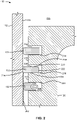
- the wall 118 may include a film of oil 202.
- the piston 126 includes a first annular groove 204, a second annular groove 206, and a third annular groove 208.
- a first land 210 separates the first annular groove 204 from the second annular groove 206, and a second land 212 separates the second annular groove 206 from the third annular groove 208.
- the first land 210 includes a first upper surface 214, which defines a floor of the first annular groove 204, and a first lower surface 216, which defines a ceiling of the second annular groove 206.
- the second land 212 includes a second upper surface 218, which defines a floor of the second annular groove 206, and a second lower surface 220, which defines a ceiling of the third annular groove 208.
- the compression ring 128 is structured and arranged within the first annular groove 204 to substantially limit the air-fuel mixture from exiting the combustion chamber 136 between the piston 126 and the wall 118.
- the scraper ring 130 which will be described below in connection with Figs. 3-6 , is structured and arranged within the second annular groove 206 to further seal the combustion chamber 136 and to substantially limit an amount of oil from the film of oil 202 entering the combustion chamber 136.
- the scraper ring 130 an interior surface 222, an exterior surface 224 that is opposite to the interior surface 222, an uppermost surface 226 that connects the interior surface 222 to the exterior surface 224, and a lowermost surface 228 that is opposite to the uppermost surface 226.
- the exterior surface 224 of the scraper ring 130 contacts the wall 118, and the lowermost surface 228 of the scraper ring 130 contacts the second upper surface 218 of the second land 212.
- the oil control ring 132 is structured and arranged within the third annular groove 208 to further limit the oil from entering the combustion chamber 136.
- the connecting rod 134 is configured to connect the piston 126 to one or more components within the crankcase 112 (e.g., a crankpin, a crank, and/or a crankshaft) to drive a drivetrain.
- Figs. 1-2 are provided as an example. Other examples may differ from what is described with regard to Figs. 1-2 .
- the number and arrangement of components e.g., the cylinder 102, the intake valve 104, the fuel injector 106, the exhaust valve 108, the crankcase 112, the piston 126, the compression ring 128, the scraper ring 130, and/or the oil control ring 132
- the power system 100 may alternatively be a gasoline engine or another type of system.
- the power system 100 may include a plurality of the cylinders 102 arranged in an in-line configuration, a "V" configuration, or another suitable configuration.
- Figs. 3-6 depict the scraper ring 130.
- a first end 302 and a second end 402 of the scraper ring 130 will be described.
- the first end 302 and the second end 402 are connected by a single, arcuate piece of material, which is referred to below as the arcuate body 304.
- the scraper ring 130 is a split ring that includes the arcuate body 304, a first projection 306, and a second projection 404.
- the arcuate body 304 includes an inner surface 308, an outer surface 310, a top surface 312, a bottom surface 314, a first end surface 316, and a second end surface 406.
- the inner surface 308 includes a chamfer 318, which facilitates sealing the scraper ring 130 against the second upper surface 218 of the second land 212 (e.g., due to a downward force of fluid trapped between the compression ring 128 and the scraper ring 130).
- the outer surface 310 which is substantially cylindrical and opposite to the inner surface 308, is configured to contact the wall 118 of the cylinder 102.
- the bottom surface 314 is configured to contact the second upper surface 218 of the second land 212 to substantially limit an amount of oil or other fluid from bypassing the scraper ring 130.
- the first projection 306 extends circumferentially from the first end surface 316 and has a substantially triangular prismatic shape.
- the first projection 306 includes a first inner surface 320, a first outer surface 322, a first contact surface 324, a first bottom surface 326, a first lateral surface 328, and a first groove 330.
- the first inner surface 320 of the first projection 306 abuts and extends from the inner surface 308 of the arcuate body 304.
- the first outer surface 322, which is opposite to the first inner surface 320, abuts and extends from the outer surface 310 of the arcuate body 304.
- the first contact surface 324 connects the first inner surface 320 to the first outer surface 322 and extends at a first angle relative to the first bottom surface 326.
- the first angle may be in a range of approximately 5 to approximately 65 degrees.
- the first angle may be in a range of approximately 10 degrees to approximately 30 degrees.
- the first bottom surface 326 which is opposite to the first contact surface 324, abuts and extends from the bottom surface 314 of the arcuate body 304.
- the first lateral surface 328 is substantially parallel to the first end surface 316.
- the first groove 330 which has a curved cross-sectional shape, extends radially from the first inner surface 320 to the first outer surface 322 between the first lateral surface 328 and the first bottom surface 326.
- the second projection 404 extends circumferentially from the second end surface 406, which includes a second groove 408 that extends radially from the inner surface 308 to the outer surface 310 of the arcuate body 304 along the bottom surface 314.
- the second projection 404 includes a second inner surface 410, a second outer surface 412, a second top surface 414, a second contact surface 416, and a second lateral surface 418.
- the second inner surface 410 which includes a second chamfer 420, abuts and extends from the inner surface 308 of the arcuate body 304.
- the second outer surface 412 which is opposite to the second inner surface 410, abuts and extends from the outer surface 310 of the arcuate body 304.
- the second top surface 414 abuts and extends from the top surface 312.
- the second contact surface 416 which is opposite to the second top surface 414, connects the second inner surface 410 to the second outer surface 412.
- the second contact surface 416 extends at a second angle relative to the second top surface 414 that is substantially equal to the first angle.
- the second angle may be in a range of approximately 5 to approximately 65 degrees.
- the second angle may be in a range of approximately 10 degrees to approximately 30 degrees.
- the second contact surface 416 is configured to slidably contact the first contact surface 324 to place the scraper ring in the overlapped state.
- the second lateral surface 418 is substantially parallel to the first end surface 316.
- the inner surface 308 of the arcuate body 304, the first inner surface 320 of the first projection 306, and the second inner surface 410 of the second projection 404 together define the interior surface 222, which extends 360 degrees about a central axis of the scraper ring 130.
- the outer surface 310 of the arcuate body 304, the first outer surface 322 of the first projection 306, and the second outer surface 412 of the second projection 404 together define the exterior surface 224, which extends 360 degrees about the central axis of the scraper ring 130.
- the exterior surface 224 of the scraper ring 130 is configured to form 360 degrees of contact with the wall 118 of the cylinder 102.
- the exterior surface 224 substantially limits an amount of oil that may travel along the wall 118 from the film of oil 202 into the combustion chamber 136.
- a lower portion 502 of the exterior surface 224 is configured to abrade away while maintaining the 360 degrees of contact with the wall 118.
- the first groove 330, the first lateral surface 328, the second groove 408, and the second end surface 406 together form a passage 504 for fluid (e.g., air, fuel, and/or oil) to flow from the interior surface 222 to the exterior surface 224 of the scraper ring 130.
- fluid e.g., air, fuel, and/or oil
- the scraper ring 130 is configured to vent the fluid regardless of the degree of overlap between the first end 302 and the second end 402 of the scraper ring 130. For example, even if the first lateral surface 328 and the second end surface 406 abut, the fluid may flow through the first groove 330 and/or the second groove 408 to relieve pressure between the compression ring 128 and the scraper ring 130.
- the scraper ring 130 is formed of a single, integral piece of material, such as stainless steel.
- the interior surface 222 of the scraper ring 130 may have a diameter in a range of approximately 50 millimeters (mm) to approximately 600 mm.
- the diameter of the interior surface 222 may be in a range of approximately 150 mm to approximately 175 mm.
- the uppermost surface 226 and/or the lowermost surface 228 of the scraper ring 130 may have a width, in a radial direction, that is greater than a distance between an exterior of the second land 212 and the wall 118.
- the width may be in a range of approximately 2 mm to approximately 25 mm.
- the width may be in a range of approximately 6 mm to approximately 7 mm.
- the interior surface 222 and/or the exterior surface 224 may have a height, in an axial direction, that is less than a height of the second annular groove 206.
- the height may be in a range of approximately 1 mm to approximately 15 mm.
- the height may be in a range of approximately 3 millimeters to approximately 4 millimeters. Other materials and/or dimensions are contemplated.
- Figs. 3-6 are provided as an example. Other examples may differ from what is described with regard to Figs. 3-6 .
- the number and arrangement of surfaces may differ from that shown in Figs. 1-2 .
- the first contact surface 324 and the second contact surface 416 may have curved shapes, a stepped shapes, serrated shapes, or another shape that allows the first contact surface 324 and the second contact surface 416 to slide relative to another while forming a seal.
- the scraper ring 130 may include only one of the first groove 330 or the second groove 408, the first groove 330 and the second grooves 408 may be have different shapes (e.g., a chamfered cross-section, a triangular cross-section, non-linear sides, and/or the like), may be provided at different and/or additional portions of the scraper ring 130, and/or may be provided, either additionally or alternatively, within the second upper surface 218 of the second land 212.
- the second upper surface 218 may include one or more radially-extending grooves having substantially the same structure and venting functionality as the first groove 330 and the second groove 408.
- the exterior surface 224 of the scraper ring 130 may be angled relative to the bottom surface 314 (e.g., at an 80 degree angle, at a 60 degree angle, and/or the like). In such an example, the lower portion 502 of the exterior surface 224 may continue to be configured to abrade away while maintaining the 360 degrees of contact with the wall 118.
- the scraper ring 130 of the present disclosure is particularly applicable to in a system that includes a movable junction between two chambers of fluid, such as the power system 100.
- the power system 100 may be implemented in a vehicle (e.g., a motor vehicle, a railed vehicle, a watercraft, an aircraft), a generator, or another machine.
- the scraper ring 130 Due to the structure and arrangement of the scraper ring 130 relative to the piston 126, the scraper ring has a number of benefits. For example, because the first end 302 and the second end 402 of the scraper ring 130 are configured to slidably overlap, the exterior surface 504 forms 360 degrees of contact with the wall 118 of the cylinder 102. As a result, the scraper ring 130 substantially limits an amount of oil that may pass from the film of oil 202 directly into the combustion chamber 136. Because of this, the scraper ring 130, relative to a typical split ring, improves performance of the power system 100 by decreasing oil consumption, surface deposits, emissions, and/or a possibility of unintentional ignition of the charge.
- the scraper ring 130 provides a vent for any fluid (e.g., air, fuel, and/or oil) that may be trapped between the compression ring 128 and the scraper ring 130.
- any fluid e.g., air, fuel, and/or oil
- Such a vent is beneficial because without it, the pressure between the compression ring 128 and the scraper ring 130 may at times be greater than the pressure in the combustion chamber 136, which may result in the fluid entering the combustion chamber 136.
- a As used herein, "a,” “an,” and a “set” are intended to include one or more items, and may be used interchangeably with “one or more.” Further, as used herein, the article “the” is intended to include one or more items referenced in connection with the article “the” and may be used interchangeably with “the one or more.” Further, the phrase “based on” is intended to mean “based, at least in part, on” unless explicitly stated otherwise. Also, as used herein, the term “or” is intended to be inclusive when used in a series and may be used interchangeably with “and/or,” unless explicitly stated otherwise (e.g., if used in combination with "either” or “only one of').
- spatially relative terms such as “below,” “lower,” “above,” “upper,” and the like, may be used herein for ease of description to describe one element or feature's relationship to another element(s) or feature(s) as illustrated in the figures.
- the spatially relative terms are intended to encompass different orientations of the apparatus, device, and/or element in use or operation in addition to the orientation depicted in the figures.
- the apparatus may be otherwise oriented (rotated 90 degrees or at other orientations) and the spatially relative descriptors used herein may likewise be interpreted accordingly.
Landscapes
- Engineering & Computer Science (AREA)
- General Engineering & Computer Science (AREA)
- Mechanical Engineering (AREA)
- Pistons, Piston Rings, And Cylinders (AREA)
Abstract
Description
- The present disclosure relates generally to a piston ring and, for example, to a scraper ring for a piston.
- A power system (e.g., a 4-stroke engine) powers a machine by converting chemical energy stored in fuel (e.g., diesel fuel, gasoline, and/or the like) into mechanical work. Depending upon the type of power system, an air-fuel mixture is either formed in a combustion chamber of a cylinder or introduced into the combustion chamber of the cylinder. A piston is mounted within the cylinder to slide along a lubricated surface in a cycle between a top dead center (TDC) position and a bottom dead center (BDC) position. As the piston moves toward the TDC position, the piston compresses the air-fuel mixture within the combustion chamber, and the fuel is ignited. A force of the explosion drives the piston down towards the BDC position, and the cycle repeats. Because the piston is connected to a drivetrain of the machine, continued movement of the piston propels and/or powers the machine.
- In order to substantially seal the combustion chamber (e.g., to substantially limit the air-fuel mixture from leaking out of the combustion chamber and/or to substantially limit oil on the lubricated surface from entering the combustion chamber), the piston includes expandable rings mounted to an outer surface thereof. However, because the expandable rings have end gaps, the expandable rings may permit a bead of the oil to flow directly into the combustion chamber. As a result, the power system may experience performance issues, such as increased oil consumption, surface deposits, emissions, and/or unintentional ignition of the charge.
-
U.S. Publication No. 2012/0112415, which published on May 10, 2012 , discloses a rotating seal ring (or piston ring). The seal ring is split to define a first free end (or arm) and a second free end (or arm) that can contact overlap one another, and which can move relative to another in a circumferential direction along a split surface located at an interface between mating cut-out notch surfaces of the first and second free ends. - The scraper ring of the present disclosure solves one or more of the problems set forth above and/or other problems in the art.
- In some implementations, a scraper ring for a piston includes an arcuate body comprising an inner surface, an outer surface, a first end surface connecting the inner surface to the outer surface, and a second end surface that is opposite to the first end surface, a first projection extending circumferentially from the first end surface, wherein the first projection comprises a first inner surface, a first outer surface, and a first contact surface connecting the first inner surface to the first outer surface; and a second projection extending circumferentially from the second end surface, wherein the second projection comprises a second inner surface, a second outer surface, and a second contact surface connecting the second inner surface to the second outer surface; wherein the first contact surface is configured to slidably contact the second contact surface to adjust a diameter of the scraper ring; and wherein, when the first contact surface contacts the second contact surface, the inner surface, the first inner surface, and the second inner surface together define an interior surface of the scraper ring that extends 360 degrees relative to a central axis of the scraper ring, and the outer surface, the first outer surface, and the second outer surface together define an exterior surface of the scraper ring that extends 360 degrees relative to the central axis; and wherein at least one of the first projection or the second end surface includes a groove to permit fluid to pass from the interior surface of the scraper ring to the exterior surface of the scraper ring.
- In some implementations, a scraper ring for a piston includes a top surface having a first planar portion and a first angled portion; a bottom surface having a second planar portion and a second angled portion, wherein the second angled portion is configured to slidably contact the first angled portion to adjust a diameter of the scraper ring; an inner surface connecting the top surface to the bottom surface; and an outer surface that is opposite to the top surface, wherein the outer surface is configured to form 360 degrees of contact with a wall of a cylinder to substantially limit an amount of oil entering a combustion chamber of the cylinder.
- In some implementations, a scraper ring includes an outer surface that is configured to form 360 degrees of contact with a wall of a cylinder in order to substantially limit oil from passing between the scraper ring and the wall to enter a combustion chamber of the cylinder; and a bottom surface that is configured to form less than 360 degrees of contact with a land of a piston to permit gas to vent between the scraper ring and the land.
-
-
Fig. 1 is an interior view of an exemplary power system including a plurality of rings. -
Fig. 2 is a cross-sectional view of the power system. -
Fig. 3 is an isometric view of a first end of a scraper ring of the plurality of rings. -
Fig. 4 is an isometric view of a second end of the scraper ring. -
Fig. 5 is a bottom isometric view of the first end and the second end of the scraper ring in an overlapped state. -
Fig. 6 is a top isometric view of the first end and the second end of the scraper ring in the overlapped state. - This disclosure relates to a ring, which is applicable to any system that includes a movable junction between two chambers of fluid. For example, the system may be a power system, and the movable junction may be a piston that separates a combustion chamber of a cylinder from an interior of a crankcase. The combustion chamber may contain an air-fuel mixture, while the interior of the crankcase may contain oil. The power system may be implemented in a vehicle (e.g., a motor vehicle, a railed vehicle, a watercraft, an aircraft), a generator, or another machine.
- To simplify the explanation below, the same reference numbers may be used to denote like features. The drawings may not be to scale.
-
Figs. 1-2 depict anexemplary power system 100. As shown inFig. 1 , thepower system 100 includes acylinder 102, anintake valve 104, afuel injector 106, anexhaust valve 108, apiston assembly 110, and acrankcase 112. Thecylinder 102 includes anupper end 114, alower end 116, and awall 118 extending between theupper end 114 and thelower end 116. Theupper end 114 of thecylinder 102 includes anair inlet 120, afuel inlet 122, and anexhaust outlet 124. Theintake valve 104 is movably seated in theair inlet 120 to allow air to pass therethrough into thecylinder 102. Thefuel injector 106 is mounted to thefuel inlet 122 to allow fuel to pass therethrough into thecylinder 102 to mix with the air to form an air-fuel mixture. Theexhaust valve 108 is movably seated in theexhaust outlet 124 to allow exhaust gas to pass therethrough to exit thecylinder 102. Thelower end 116 of thecylinder 102 is connected to thecrankcase 112. - The
piston assembly 110 includes apiston 126, acompression ring 128, ascraper ring 130, anoil control ring 132, and a connectingrod 134. Thepiston 126, which defines a lower end of acombustion chamber 136, is slidably mounted within thecylinder 102 to travel in a 4-stroke cycle (including an intake stroke, a compression stroke, a combustion stroke, and an exhaust stroke) to convert chemical energy stored in the fuel into mechanical work. As shown inFig. 2 , to minimize friction between thepiston 126 and thewall 118, thewall 118 may include a film ofoil 202. Thepiston 126 includes a firstannular groove 204, a secondannular groove 206, and a thirdannular groove 208. Afirst land 210 separates the firstannular groove 204 from the secondannular groove 206, and asecond land 212 separates the secondannular groove 206 from the thirdannular groove 208. In other words, thefirst land 210 includes a firstupper surface 214, which defines a floor of the firstannular groove 204, and a firstlower surface 216, which defines a ceiling of the secondannular groove 206. Thesecond land 212, in turn, includes a secondupper surface 218, which defines a floor of the secondannular groove 206, and a secondlower surface 220, which defines a ceiling of the thirdannular groove 208. - The
compression ring 128 is structured and arranged within the firstannular groove 204 to substantially limit the air-fuel mixture from exiting thecombustion chamber 136 between thepiston 126 and thewall 118. Thescraper ring 130, which will be described below in connection withFigs. 3-6 , is structured and arranged within the secondannular groove 206 to further seal thecombustion chamber 136 and to substantially limit an amount of oil from the film ofoil 202 entering thecombustion chamber 136. Thescraper ring 130 aninterior surface 222, anexterior surface 224 that is opposite to theinterior surface 222, anuppermost surface 226 that connects theinterior surface 222 to theexterior surface 224, and alowermost surface 228 that is opposite to theuppermost surface 226. In use, theexterior surface 224 of thescraper ring 130 contacts thewall 118, and thelowermost surface 228 of thescraper ring 130 contacts the secondupper surface 218 of thesecond land 212. Theoil control ring 132 is structured and arranged within the thirdannular groove 208 to further limit the oil from entering thecombustion chamber 136. The connectingrod 134 is configured to connect thepiston 126 to one or more components within the crankcase 112 (e.g., a crankpin, a crank, and/or a crankshaft) to drive a drivetrain. - As indicated above,
Figs. 1-2 are provided as an example. Other examples may differ from what is described with regard toFigs. 1-2 . For example, the number and arrangement of components (e.g., thecylinder 102, theintake valve 104, thefuel injector 106, theexhaust valve 108, thecrankcase 112, thepiston 126, thecompression ring 128, thescraper ring 130, and/or the oil control ring 132) may differ from that shown inFigs. 1-2 . Thus, there may be additional components, fewer components, different components, differently shaped components, and/or differently arranged components than those shown inFigs. 1-2 . Furthermore, as indicated above, it should be understood that thepower system 100, though shown and described above as a diesel engine, may alternatively be a gasoline engine or another type of system. Thepower system 100 may include a plurality of thecylinders 102 arranged in an in-line configuration, a "V" configuration, or another suitable configuration. -
Figs. 3-6 depict thescraper ring 130. In the description to follow, afirst end 302 and asecond end 402 of thescraper ring 130 will be described. However, it should be understood that thefirst end 302 and thesecond end 402 are connected by a single, arcuate piece of material, which is referred to below as thearcuate body 304. - As shown in
Figs. 3-6 , thescraper ring 130 is a split ring that includes thearcuate body 304, afirst projection 306, and asecond projection 404. Thearcuate body 304 includes aninner surface 308, anouter surface 310, atop surface 312, abottom surface 314, afirst end surface 316, and asecond end surface 406. Theinner surface 308 includes achamfer 318, which facilitates sealing thescraper ring 130 against the secondupper surface 218 of the second land 212 (e.g., due to a downward force of fluid trapped between thecompression ring 128 and the scraper ring 130). Theouter surface 310, which is substantially cylindrical and opposite to theinner surface 308, is configured to contact thewall 118 of thecylinder 102. Thetop surface 312, which defines theuppermost surface 226 of thescraper ring 130, is substantially planar and connects theinner surface 308 to theouter surface 310. Thebottom surface 314, which defines thelowermost surface 228 of thescraper ring 130 and is also substantially planar, is opposite to thetop surface 312. Thebottom surface 314 is configured to contact the secondupper surface 218 of thesecond land 212 to substantially limit an amount of oil or other fluid from bypassing thescraper ring 130. - The
first projection 306 extends circumferentially from thefirst end surface 316 and has a substantially triangular prismatic shape. Thefirst projection 306 includes a firstinner surface 320, a firstouter surface 322, afirst contact surface 324, a firstbottom surface 326, a firstlateral surface 328, and afirst groove 330. The firstinner surface 320 of thefirst projection 306 abuts and extends from theinner surface 308 of thearcuate body 304. The firstouter surface 322, which is opposite to the firstinner surface 320, abuts and extends from theouter surface 310 of thearcuate body 304. Thefirst contact surface 324 connects the firstinner surface 320 to the firstouter surface 322 and extends at a first angle relative to the firstbottom surface 326. For example, the first angle may be in a range of approximately 5 to approximately 65 degrees. As a further example, the first angle may be in a range of approximately 10 degrees to approximately 30 degrees. The firstbottom surface 326, which is opposite to thefirst contact surface 324, abuts and extends from thebottom surface 314 of thearcuate body 304. The firstlateral surface 328 is substantially parallel to thefirst end surface 316. Thefirst groove 330, which has a curved cross-sectional shape, extends radially from the firstinner surface 320 to the firstouter surface 322 between the firstlateral surface 328 and the firstbottom surface 326. - The
second projection 404 extends circumferentially from thesecond end surface 406, which includes asecond groove 408 that extends radially from theinner surface 308 to theouter surface 310 of thearcuate body 304 along thebottom surface 314. Thesecond projection 404 includes a secondinner surface 410, a secondouter surface 412, a secondtop surface 414, asecond contact surface 416, and a secondlateral surface 418. The secondinner surface 410, which includes asecond chamfer 420, abuts and extends from theinner surface 308 of thearcuate body 304. The secondouter surface 412, which is opposite to the secondinner surface 410, abuts and extends from theouter surface 310 of thearcuate body 304. The secondtop surface 414 abuts and extends from thetop surface 312. Thesecond contact surface 416, which is opposite to the secondtop surface 414, connects the secondinner surface 410 to the secondouter surface 412. In order to form a seal with thefirst contact surface 324, thesecond contact surface 416 extends at a second angle relative to the secondtop surface 414 that is substantially equal to the first angle. For example, the second angle may be in a range of approximately 5 to approximately 65 degrees. As a further example, the second angle may be in a range of approximately 10 degrees to approximately 30 degrees. Thus, thesecond contact surface 416 is configured to slidably contact thefirst contact surface 324 to place the scraper ring in the overlapped state. The secondlateral surface 418 is substantially parallel to thefirst end surface 316. - When the
scraper ring 130 is in the overlapped state (as shown inFigs. 5-6 ), theinner surface 308 of thearcuate body 304, the firstinner surface 320 of thefirst projection 306, and the secondinner surface 410 of thesecond projection 404 together define theinterior surface 222, which extends 360 degrees about a central axis of thescraper ring 130. Likewise, theouter surface 310 of thearcuate body 304, the firstouter surface 322 of thefirst projection 306, and the secondouter surface 412 of thesecond projection 404 together define theexterior surface 224, which extends 360 degrees about the central axis of thescraper ring 130. In other words, when thescraper ring 130 is positioned within the secondannular groove 206 of thepiston 126, theexterior surface 224 of thescraper ring 130 is configured to form 360 degrees of contact with thewall 118 of thecylinder 102. Thus, theexterior surface 224 substantially limits an amount of oil that may travel along thewall 118 from the film ofoil 202 into thecombustion chamber 136. Over time, and due to the contact with thewall 118, alower portion 502 of the exterior surface 224 (as shown by the dotted line) is configured to abrade away while maintaining the 360 degrees of contact with thewall 118. Thefirst groove 330, the firstlateral surface 328, thesecond groove 408, and thesecond end surface 406 together form apassage 504 for fluid (e.g., air, fuel, and/or oil) to flow from theinterior surface 222 to theexterior surface 224 of thescraper ring 130. By including thefirst groove 330 and/or thesecond groove 408 in thescraper ring 130, thescraper ring 130 is configured to vent the fluid regardless of the degree of overlap between thefirst end 302 and thesecond end 402 of thescraper ring 130. For example, even if the firstlateral surface 328 and thesecond end surface 406 abut, the fluid may flow through thefirst groove 330 and/or thesecond groove 408 to relieve pressure between thecompression ring 128 and thescraper ring 130. - The
scraper ring 130 is formed of a single, integral piece of material, such as stainless steel. In order to fit within the secondannular groove 206 of thepiston 126, theinterior surface 222 of thescraper ring 130 may have a diameter in a range of approximately 50 millimeters (mm) to approximately 600 mm. As an example, the diameter of theinterior surface 222 may be in a range of approximately 150 mm to approximately 175 mm. Theuppermost surface 226 and/or thelowermost surface 228 of thescraper ring 130 may have a width, in a radial direction, that is greater than a distance between an exterior of thesecond land 212 and thewall 118. For example, the width may be in a range of approximately 2 mm to approximately 25 mm. As a further example, the width may be in a range of approximately 6 mm to approximately 7 mm. In order to allow fluid (e.g., the air-fuel mixture) to enter the secondannular groove 206 to press thescraper ring 130 against thewall 118 and the secondupper surface 218 of thesecond land 212, theinterior surface 222 and/or theexterior surface 224 may have a height, in an axial direction, that is less than a height of the secondannular groove 206. For example, the height may be in a range of approximately 1 mm to approximately 15 mm. As a further example, the height may be in a range of approximately 3 millimeters to approximately 4 millimeters. Other materials and/or dimensions are contemplated. - As indicated above,
Figs. 3-6 are provided as an example. Other examples may differ from what is described with regard toFigs. 3-6 . For example, the number and arrangement of surfaces may differ from that shown inFigs. 1-2 . Thus, there may be additional surfaces, fewer surfaces, and/or differently shaped surfaces than those shown inFigs. 3-6 . For example, thefirst contact surface 324 and thesecond contact surface 416 may have curved shapes, a stepped shapes, serrated shapes, or another shape that allows thefirst contact surface 324 and thesecond contact surface 416 to slide relative to another while forming a seal. As another example, thescraper ring 130 may include only one of thefirst groove 330 or thesecond groove 408, thefirst groove 330 and thesecond grooves 408 may be have different shapes (e.g., a chamfered cross-section, a triangular cross-section, non-linear sides, and/or the like), may be provided at different and/or additional portions of thescraper ring 130, and/or may be provided, either additionally or alternatively, within the secondupper surface 218 of thesecond land 212. For example, in some implementations, the secondupper surface 218 may include one or more radially-extending grooves having substantially the same structure and venting functionality as thefirst groove 330 and thesecond groove 408. As a further example, theexterior surface 224 of thescraper ring 130 may be angled relative to the bottom surface 314 (e.g., at an 80 degree angle, at a 60 degree angle, and/or the like). In such an example, thelower portion 502 of theexterior surface 224 may continue to be configured to abrade away while maintaining the 360 degrees of contact with thewall 118. - The
scraper ring 130 of the present disclosure is particularly applicable to in a system that includes a movable junction between two chambers of fluid, such as thepower system 100. Thepower system 100 may be implemented in a vehicle (e.g., a motor vehicle, a railed vehicle, a watercraft, an aircraft), a generator, or another machine. - Due to the structure and arrangement of the
scraper ring 130 relative to thepiston 126, the scraper ring has a number of benefits. For example, because thefirst end 302 and thesecond end 402 of thescraper ring 130 are configured to slidably overlap, theexterior surface 504 forms 360 degrees of contact with thewall 118 of thecylinder 102. As a result, thescraper ring 130 substantially limits an amount of oil that may pass from the film ofoil 202 directly into thecombustion chamber 136. Because of this, thescraper ring 130, relative to a typical split ring, improves performance of thepower system 100 by decreasing oil consumption, surface deposits, emissions, and/or a possibility of unintentional ignition of the charge. Furthermore, by including thefirst groove 330 and/or thesecond groove 408, thescraper ring 130 provides a vent for any fluid (e.g., air, fuel, and/or oil) that may be trapped between thecompression ring 128 and thescraper ring 130. Such a vent is beneficial because without it, the pressure between thecompression ring 128 and thescraper ring 130 may at times be greater than the pressure in thecombustion chamber 136, which may result in the fluid entering thecombustion chamber 136. - The foregoing disclosure provides illustration and description, but is not intended to be exhaustive or to limit the implementations to the precise form disclosed. Modifications and variations may be made in light of the above disclosure or may be acquired from practice of the implementations. Furthermore, any of the implementations described herein may be combined unless the foregoing disclosure expressly provides a reason that one or more implementations cannot be combined. Even though particular combinations of features are recited in the claims and/or disclosed in the specification, these combinations are not intended to limit the disclosure of various implementations. Although each dependent claim listed below may directly depend on only one claim, the disclosure of various implementations includes each dependent claim in combination with every other claim in the claim set.
- As used herein, "a," "an," and a "set" are intended to include one or more items, and may be used interchangeably with "one or more." Further, as used herein, the article "the" is intended to include one or more items referenced in connection with the article "the" and may be used interchangeably with "the one or more." Further, the phrase "based on" is intended to mean "based, at least in part, on" unless explicitly stated otherwise. Also, as used herein, the term "or" is intended to be inclusive when used in a series and may be used interchangeably with "and/or," unless explicitly stated otherwise (e.g., if used in combination with "either" or "only one of'). Further, spatially relative terms, such as "below," "lower," "above," "upper," and the like, may be used herein for ease of description to describe one element or feature's relationship to another element(s) or feature(s) as illustrated in the figures. The spatially relative terms are intended to encompass different orientations of the apparatus, device, and/or element in use or operation in addition to the orientation depicted in the figures. The apparatus may be otherwise oriented (rotated 90 degrees or at other orientations) and the spatially relative descriptors used herein may likewise be interpreted accordingly.
Claims (10)
- A scraper ring (130) for a piston (126), comprising:an arcuate body (304) comprising an inner surface (308), an outer surface (310), a first end surface (316) connecting the inner surface (308) to the outer surface (310), and a second end surface (406) opposite to the first end surface (316),a first projection (306) extending circumferentially from the first end surface (316),
wherein the first projection (306) comprises a first inner surface (320), a first outer surface (322), and a first contact surface (324) connecting the first inner surface (320) to the first outer surface (322); anda second projection (404) extending circumferentially from the second end surface (406),
wherein the second projection (404) comprises a second inner surface (410), a second outer surface (412), and a second contact surface (416) connecting the second inner surface (410) to the second outer surface (412);wherein the first contact surface (324) is configured to slidably contact the second contact surface (416) to adjust a diameter of the scraper ring (130); andwherein, when the first contact surface (324) contacts the second contact surface (416),the inner surface (308), the first inner surface (320), and the second inner surface (410) together define an interior surface (502) of the scraper ring (130) that extends 360 degrees relative to a central axis of the scraper ring (130), andthe outer surface (310), the first outer surface (322), and the second outer surface (412) together define an exterior surface (504) of the scraper ring (130) that extends 360 degrees relative to the central axis; andwherein at least one of the first projection (306) or the second end surface (406) includes a groove (330, 408) to permit fluid to pass from the interior surface (502) of the scraper ring (130) to the exterior surface (504) of the scraper ring (130). - The scraper ring (130) of claim 1, whereinthe arcuate body (304) further includes:a bottom surface (314) connecting the inner surface (308) to the outer surface (310), anda top surface (312) opposite to the bottom surface (314);the first projection (306) further includes a first bottom surface (326) that is substantially co-planar with the bottom surface (314); andthe second projection (404) further includes a second top surface (414) that is substantially co-planar with the top surface (312).
- The scraper ring (130) of claim 2, whereinthe first contact surface (324) extends at an angle relative to the first bottom surface (326); andthe second contact surface (416) extends at the angle relative to the second top surface (414).
- The scraper ring (130) of claim 3, wherein the angle is in a range of approximately 10 degrees to approximately 30 degrees.
- The scraper ring (130) of any of claims 2-4, whereinthe at least one of the first projection (306) or the second end surface (406) is the first projection (306); andthe groove (330) extends along the first bottom surface (326) of the first projection (306) between the first inner surface (320) and the first outer surface (322) of the first projection (306).
- A scraper ring (130) for a piston (126), comprising:a top surface (312, 324, 414) having a first planar portion (312, 414) and a first angled portion (324);a bottom surface (314, 326, 416) having a second planar portion (314, 326) and a second angled portion (416),
wherein the second angled portion (416) is configured to slidably contact the first angled portion (324) to adjust a diameter of the scraper ring (130);an inner surface (308, 320, 410) connecting the top surface (312, 324, 414) to the bottom surface (314, 326, 416); andan outer surface (310, 322, 412) opposite to the inner surface (308, 320, 410),
wherein the outer surface (310, 322, 412) is configured to form 360 degrees of contact with a wall (118) of a cylinder (102) to substantially limit an amount of oil entering a combustion chamber (136) of the cylinder (102). - The scraper ring (130) of claim 6, wherein the inner surface (308, 320, 410) includes a chamfer (318, 420).
- The scraper ring (130) of any of claims 6-7, wherein the bottom surface (314, 326, 416) includes:a first groove (330) that extends between the inner surface (308, 320, 410) and the outer surface (310, 322, 412); anda second groove (408) that extends between the inner surface (308, 320, 410) and the outer surface (310, 322, 412).
- The scraper ring (130) of any of claims 6-8, whereinthe inner surface (308, 320, 410) of the scraper ring (130) defines the diameter; andwhen the first angled portion (324) contacts the second angled portion (416), the diameter of the scraper ring (130) is in a range of approximately 150 millimeters to approximately 175 millimeters.
- The scraper ring (130) of any of claims 6-9, whereinthe scraper ring (130) has a height in a range of approximately 3 millimeters to approximately 4 millimeters; andthe scraper ring (130) has a width in a range of approximately 6 millimeters to approximately 7 millimeters.
Applications Claiming Priority (1)
| Application Number | Priority Date | Filing Date | Title |
|---|---|---|---|
| US17/247,493 US11674595B2 (en) | 2020-12-14 | 2020-12-14 | Scraper ring for a piston |
Publications (1)
| Publication Number | Publication Date |
|---|---|
| EP4012232A1 true EP4012232A1 (en) | 2022-06-15 |
Family
ID=78709243
Family Applications (1)
| Application Number | Title | Priority Date | Filing Date |
|---|---|---|---|
| EP21209155.7A Pending EP4012232A1 (en) | 2020-12-14 | 2021-11-18 | Scraper ring for a piston |
Country Status (3)
| Country | Link |
|---|---|
| US (1) | US11674595B2 (en) |
| EP (1) | EP4012232A1 (en) |
| CN (1) | CN114623232A (en) |
Citations (5)
| Publication number | Priority date | Publication date | Assignee | Title |
|---|---|---|---|---|
| US1489335A (en) * | 1920-06-17 | 1924-04-08 | Seifert Henry Richard | Piston ring |
| JPS601469A (en) * | 1983-06-16 | 1985-01-07 | Nissan Motor Co Ltd | Piston ring device |
| GB2151721A (en) * | 1983-12-16 | 1985-07-24 | Ford Motor Co | Sealing ring relatively rotating machine parts |
| CN101929545A (en) * | 2009-06-19 | 2010-12-29 | 徐春桂 | Rupture-preventing sealing piston ring |
| US20120112415A1 (en) | 2010-11-10 | 2012-05-10 | United Technologies Corporation | Rotating seal ring with targeted split surface orientation |
Family Cites Families (16)
| Publication number | Priority date | Publication date | Assignee | Title |
|---|---|---|---|---|
| US1345804A (en) * | 1917-11-28 | 1920-07-06 | Edward R Norman | Packing-ring |
| US1365348A (en) * | 1918-12-11 | 1921-01-11 | Shetler Melvin | Piston-ring |
| US1532547A (en) * | 1919-11-17 | 1925-04-07 | Pruyn John Ernest | Piston ring |
| US1512393A (en) * | 1924-03-26 | 1924-10-21 | Leo R Behnke | Piston ring |
| US1833887A (en) * | 1930-12-03 | 1931-12-01 | William C Andrews | Piston ring |
| US2112103A (en) * | 1935-09-11 | 1938-03-22 | Sylvan R White | Oil ring |
| JPS601469B2 (en) | 1977-08-05 | 1985-01-14 | 清水建設株式会社 | Edge cutting jacking method in sliding form construction method |
| US4189161A (en) * | 1978-08-28 | 1980-02-19 | Muskegon Piston Ring Company | Bi-directional ring gap seal |
| US4848212A (en) * | 1986-04-24 | 1989-07-18 | Mazda Motor Corporation | Internal combustion engine piston with two compression rings having reduced oil consumption |
| JP2006017287A (en) | 2004-07-05 | 2006-01-19 | Riken Corp | Piston ring for internal combustion engine |
| CN101042191A (en) * | 2005-12-25 | 2007-09-26 | 宇秀明 | Sealed oil ring |
| US8017057B2 (en) * | 2006-06-15 | 2011-09-13 | E. I. Du Pont De Nemours And Company | Method for making a pressed part with separations or voids |
| CN101581259A (en) * | 2008-05-15 | 2009-11-18 | 高敦华 | Method for establishing piston ring mechanism for sealing single-ring piston engine |
| JP5106376B2 (en) * | 2008-12-25 | 2012-12-26 | Tpr株式会社 | Piston device for internal combustion engine |
| JP5781332B2 (en) | 2011-02-28 | 2015-09-24 | 三菱重工業株式会社 | piston ring |
| EP2551503A1 (en) * | 2011-07-25 | 2013-01-30 | Wärtsilä Schweiz AG | Piston, piston ring and oil distribution ring for a stroke piston combustion engine |
-
2020
- 2020-12-14 US US17/247,493 patent/US11674595B2/en active Active
-
2021
- 2021-11-18 EP EP21209155.7A patent/EP4012232A1/en active Pending
- 2021-12-03 CN CN202111465381.7A patent/CN114623232A/en active Pending
Patent Citations (5)
| Publication number | Priority date | Publication date | Assignee | Title |
|---|---|---|---|---|
| US1489335A (en) * | 1920-06-17 | 1924-04-08 | Seifert Henry Richard | Piston ring |
| JPS601469A (en) * | 1983-06-16 | 1985-01-07 | Nissan Motor Co Ltd | Piston ring device |
| GB2151721A (en) * | 1983-12-16 | 1985-07-24 | Ford Motor Co | Sealing ring relatively rotating machine parts |
| CN101929545A (en) * | 2009-06-19 | 2010-12-29 | 徐春桂 | Rupture-preventing sealing piston ring |
| US20120112415A1 (en) | 2010-11-10 | 2012-05-10 | United Technologies Corporation | Rotating seal ring with targeted split surface orientation |
Also Published As
| Publication number | Publication date |
|---|---|
| CN114623232A (en) | 2022-06-14 |
| US20220186833A1 (en) | 2022-06-16 |
| US11674595B2 (en) | 2023-06-13 |
Similar Documents
| Publication | Publication Date | Title |
|---|---|---|
| US20090020958A1 (en) | Methods and apparatus for operating an internal combustion engine | |
| US5052349A (en) | Rotary valve for internal combustion engine | |
| US9938925B2 (en) | Cylinder liner with chamfer and anti-polishing cuff | |
| KR102002662B1 (en) | Piston ring for an internal combustion engine | |
| EP3412940B1 (en) | Piston ring for an internal combustion engine | |
| US7866295B2 (en) | Piston skirt oil retention for an internal combustion engine | |
| US20140000549A1 (en) | Compression ring for an engine | |
| EP2746553A1 (en) | Unburned fuel venting in internal combustion engines | |
| EP2815156B1 (en) | Piston ring for an internal combustion engine | |
| US11674595B2 (en) | Scraper ring for a piston | |
| EP2746531A1 (en) | Unburned fuel venting in internal combustion engines | |
| US20080271597A1 (en) | Methods and apparatus for operating an internal combustion engine | |
| US11946434B1 (en) | System and method for enclosing piston cooling gallery | |
| US11313466B2 (en) | Piston assembly for an internal combustion engine of a motor vehicle | |
| WO2026030022A1 (en) | Seal for cylinder liner assembly and method for making the same | |
| KR20140123585A (en) | Piston ring for an internal combustion engine |
Legal Events
| Date | Code | Title | Description |
|---|---|---|---|
| PUAI | Public reference made under article 153(3) epc to a published international application that has entered the european phase |
Free format text: ORIGINAL CODE: 0009012 |
|
| STAA | Information on the status of an ep patent application or granted ep patent |
Free format text: STATUS: THE APPLICATION HAS BEEN PUBLISHED |
|
| AK | Designated contracting states |
Kind code of ref document: A1 Designated state(s): AL AT BE BG CH CY CZ DE DK EE ES FI FR GB GR HR HU IE IS IT LI LT LU LV MC MK MT NL NO PL PT RO RS SE SI SK SM TR |
|
| STAA | Information on the status of an ep patent application or granted ep patent |
Free format text: STATUS: REQUEST FOR EXAMINATION WAS MADE |
|
| 17P | Request for examination filed |
Effective date: 20221214 |
|
| RBV | Designated contracting states (corrected) |
Designated state(s): AL AT BE BG CH CY CZ DE DK EE ES FI FR GB GR HR HU IE IS IT LI LT LU LV MC MK MT NL NO PL PT RO RS SE SI SK SM TR |
|
| STAA | Information on the status of an ep patent application or granted ep patent |
Free format text: STATUS: EXAMINATION IS IN PROGRESS |
|
| 17Q | First examination report despatched |
Effective date: 20240422 |