EP4012211A1 - A bearing housing for a flow machine and a flow machine with a bearing housing - Google Patents
A bearing housing for a flow machine and a flow machine with a bearing housing Download PDFInfo
- Publication number
- EP4012211A1 EP4012211A1 EP20213791.5A EP20213791A EP4012211A1 EP 4012211 A1 EP4012211 A1 EP 4012211A1 EP 20213791 A EP20213791 A EP 20213791A EP 4012211 A1 EP4012211 A1 EP 4012211A1
- Authority
- EP
- European Patent Office
- Prior art keywords
- bearing
- lubricant
- chamber
- bearing housing
- cooling fin
- Prior art date
- Legal status (The legal status is an assumption and is not a legal conclusion. Google has not performed a legal analysis and makes no representation as to the accuracy of the status listed.)
- Granted
Links
Images

Classifications
-
- F—MECHANICAL ENGINEERING; LIGHTING; HEATING; WEAPONS; BLASTING
- F16—ENGINEERING ELEMENTS AND UNITS; GENERAL MEASURES FOR PRODUCING AND MAINTAINING EFFECTIVE FUNCTIONING OF MACHINES OR INSTALLATIONS; THERMAL INSULATION IN GENERAL
- F16C—SHAFTS; FLEXIBLE SHAFTS; ELEMENTS OR CRANKSHAFT MECHANISMS; ROTARY BODIES OTHER THAN GEARING ELEMENTS; BEARINGS
- F16C37/00—Cooling of bearings
- F16C37/007—Cooling of bearings of rolling bearings
-
- F—MECHANICAL ENGINEERING; LIGHTING; HEATING; WEAPONS; BLASTING
- F04—POSITIVE - DISPLACEMENT MACHINES FOR LIQUIDS; PUMPS FOR LIQUIDS OR ELASTIC FLUIDS
- F04D—NON-POSITIVE-DISPLACEMENT PUMPS
- F04D1/00—Radial-flow pumps, e.g. centrifugal pumps; Helico-centrifugal pumps
- F04D1/06—Multi-stage pumps
-
- F—MECHANICAL ENGINEERING; LIGHTING; HEATING; WEAPONS; BLASTING
- F04—POSITIVE - DISPLACEMENT MACHINES FOR LIQUIDS; PUMPS FOR LIQUIDS OR ELASTIC FLUIDS
- F04D—NON-POSITIVE-DISPLACEMENT PUMPS
- F04D29/00—Details, component parts, or accessories
- F04D29/04—Shafts or bearings, or assemblies thereof
- F04D29/046—Bearings
- F04D29/0462—Bearing cartridges
-
- F—MECHANICAL ENGINEERING; LIGHTING; HEATING; WEAPONS; BLASTING
- F04—POSITIVE - DISPLACEMENT MACHINES FOR LIQUIDS; PUMPS FOR LIQUIDS OR ELASTIC FLUIDS
- F04D—NON-POSITIVE-DISPLACEMENT PUMPS
- F04D29/00—Details, component parts, or accessories
- F04D29/04—Shafts or bearings, or assemblies thereof
- F04D29/046—Bearings
- F04D29/047—Bearings hydrostatic; hydrodynamic
- F04D29/0473—Bearings hydrostatic; hydrodynamic for radial pumps
-
- F—MECHANICAL ENGINEERING; LIGHTING; HEATING; WEAPONS; BLASTING
- F04—POSITIVE - DISPLACEMENT MACHINES FOR LIQUIDS; PUMPS FOR LIQUIDS OR ELASTIC FLUIDS
- F04D—NON-POSITIVE-DISPLACEMENT PUMPS
- F04D29/00—Details, component parts, or accessories
- F04D29/06—Lubrication
- F04D29/061—Lubrication especially adapted for liquid pumps
-
- F—MECHANICAL ENGINEERING; LIGHTING; HEATING; WEAPONS; BLASTING
- F04—POSITIVE - DISPLACEMENT MACHINES FOR LIQUIDS; PUMPS FOR LIQUIDS OR ELASTIC FLUIDS
- F04D—NON-POSITIVE-DISPLACEMENT PUMPS
- F04D29/00—Details, component parts, or accessories
- F04D29/58—Cooling; Heating; Diminishing heat transfer
- F04D29/586—Cooling; Heating; Diminishing heat transfer specially adapted for liquid pumps
- F04D29/588—Cooling; Heating; Diminishing heat transfer specially adapted for liquid pumps cooling or heating the machine
-
- F—MECHANICAL ENGINEERING; LIGHTING; HEATING; WEAPONS; BLASTING
- F16—ENGINEERING ELEMENTS AND UNITS; GENERAL MEASURES FOR PRODUCING AND MAINTAINING EFFECTIVE FUNCTIONING OF MACHINES OR INSTALLATIONS; THERMAL INSULATION IN GENERAL
- F16C—SHAFTS; FLEXIBLE SHAFTS; ELEMENTS OR CRANKSHAFT MECHANISMS; ROTARY BODIES OTHER THAN GEARING ELEMENTS; BEARINGS
- F16C33/00—Parts of bearings; Special methods for making bearings or parts thereof
- F16C33/30—Parts of ball or roller bearings
- F16C33/66—Special parts or details in view of lubrication
- F16C33/6637—Special parts or details in view of lubrication with liquid lubricant
- F16C33/6659—Details of supply of the liquid to the bearing, e.g. passages or nozzles
- F16C33/667—Details of supply of the liquid to the bearing, e.g. passages or nozzles related to conditioning, e.g. cooling, filtering
-
- F—MECHANICAL ENGINEERING; LIGHTING; HEATING; WEAPONS; BLASTING
- F16—ENGINEERING ELEMENTS AND UNITS; GENERAL MEASURES FOR PRODUCING AND MAINTAINING EFFECTIVE FUNCTIONING OF MACHINES OR INSTALLATIONS; THERMAL INSULATION IN GENERAL
- F16C—SHAFTS; FLEXIBLE SHAFTS; ELEMENTS OR CRANKSHAFT MECHANISMS; ROTARY BODIES OTHER THAN GEARING ELEMENTS; BEARINGS
- F16C35/00—Rigid support of bearing units; Housings, e.g. caps, covers
- F16C35/04—Rigid support of bearing units; Housings, e.g. caps, covers in the case of ball or roller bearings
- F16C35/042—Housings for rolling element bearings for rotary movement
-
- F—MECHANICAL ENGINEERING; LIGHTING; HEATING; WEAPONS; BLASTING
- F16—ENGINEERING ELEMENTS AND UNITS; GENERAL MEASURES FOR PRODUCING AND MAINTAINING EFFECTIVE FUNCTIONING OF MACHINES OR INSTALLATIONS; THERMAL INSULATION IN GENERAL
- F16C—SHAFTS; FLEXIBLE SHAFTS; ELEMENTS OR CRANKSHAFT MECHANISMS; ROTARY BODIES OTHER THAN GEARING ELEMENTS; BEARINGS
- F16C2360/00—Engines or pumps
- F16C2360/44—Centrifugal pumps
Definitions
- the invention relates to a bearing housing for a flow machine according to the preamble of the independent claim 1.
- the invention further relates to a flow machine with a bearing housing according to the independent claim 11.
- Flow machines for conveying a fluid typically comprise a stationary machine housing that encloses a rotor, e.g. an impeller, which is arranged on a shaft rotating around an axis of the flow machine.
- the flow machine also has at least one bearing unit with a radial and / or axial (thrust) bearing to support the shaft and the rotor.
- the bearing unit has a separate bearing housing that is firmly connected to the housing of the flow machine.
- the bearing housing comprises a bearing axis, a bearing chamber for receiving the bearing and a lubricant chamber for receiving a lubricant.
- the lubricant chamber and the bearing chamber are in fluid communication via an opening, so that the bearing can be cooled and lubricated by means of the lubricant during operation of the flow machine.
- the lubricant chamber has a wall portion for dissipating heat to the environment, wherein the wall portion has both an inner surface directed towards the lubricant chamber and an outer surface directed towards the environment.
- cooling fins are not required but are typically included to increase the surface area of the housing and therefore the overall cooling capacity. These cooling fins are part of the housing and not a separate item. In another way, cooling can also be achieved by water or by increasing the size of the lubricant chamber and/or by increasing the amount of lubricant. The current methods cool the housing itself and the lubricant is only cooled indirectly through being in contact with the housing. This is very inefficient and limits the maximum heat dissipation across the bearings.
- the invention relates to a bearing housing for a flow machine, wherein the bearing housing comprises a bearing chamber for receiving a bearing and a lubricant chamber arranged at the bearing chamber for receiving a lubricant.
- the bearing chamber is in fluid communication with the lubricant chamber via an opening such that the lubricant can flow between the bearing chamber and the lubricant chamber.
- the bearing housing comprises a wall portion with a cooling fin for dissipating a heat of the lubricant to an environment.
- the cooling fin comprises a conduit for the lubricant through which conduit the lubricant chamber and the bearing chamber are in fluid communication such that the lubricant can be conducted from the lubricant chamber into the bearing chamber through the conduit to dissipate heat to the environment.
- the bearing housing according to the invention has a cooling fin, which cooling fin increases the total surface area of the bearing housing, which increases the heat exchange with the environment as the heat of the lubricant can be more effectively transferred to the environment through the lubricant flowing through the cooling fin, since the heat exchange between the lubricant and the wall portion for the dissipation of heat to the environment is increased.
- the lubricant flows through the conduit in the cooling fin and is thereby directly cooled by the cooling fin and not only indirectly through being in contact with the bearing housing of the lubricant chamber. This is very efficient and enlarges the maximum heat dissipation across the bearing housing.
- the conduit is preferably arranged meandering in the cooling fin such that a majority of a volume of the cooling fin is filled through the conduit.
- the majority of the volume of the cooling fin is 50 to 90 %, especially 60 to 80 % of the volume of the cooling fin.
- the cooling fin is arranged on an outer surface of the wall portion (external cooling fin), which outer surface is directed towards the environment.
- the lubricant chamber is filled with the lubricant up to a lubricant level in the operating state and the cooling fin is designed as internal cooling fin extending inside the lubricant chamber preferably completely below the lubricant level.
- the bearing housing can comprise external and internal cooling fins. This increases the overall surface area available for heat exchange between the bearing housing and the environment.
- the cooling fin can comprise a cooling conduit through which cooling conduit a cooling fluid is flowable to additionally cool the lubricant which is flowable through the conduit.
- the lubricant can be guided from the lubricant chamber through the conduit in the cooling fins to the bearing housing (and through the opening back to the lubricant chamber or directly to the bearing) via a forced oil circulation. It has proven to be advantageous if the opening is formed as a slot. This results in an improved supply of lubricant from the bearing chamber into the lubricant chamber and an enlarged lubricant circulation.
- the slot extends in the direction of the bearing axis.
- the bearing housing can comprise a bearing axis, wherein the cooling fin extends in the direction of the bearing axis and / or wherein the cooling fin extends in a circumferential direction with respect to the bearing axis.
- the cooling fin can extend from the outer surface in a vertical direction to the bearing axis. This simplifies the production of the bearing housing.
- the cooling fin extends spirally with respect to the bearing axis.
- the cooling fin can be designed in such a way that it has a substantially rectangular cross-sectional area in a section perpendicular to the bearing axis.
- the bearing housing can comprise a plurality of cooling fins.
- the cooling fins can be designed as fin stack, which comprises a plurality of cooling fins.
- the bearing housing can also comprise a plurality of fin stacks.
- the cooling fin is detachably arranged on the bearing housing, in particular is detachably screwed to the bearing housing.
- the cooling fin is therefore removable and can be constructed via additive manufacturing or traditional methods.
- the removable cooling fins allows changing of the cooling fins to suit bearing heat load and environmental conditions.
- the plurality of cooling fins can be increased (attached) by a settable number of cooling fins if there is a high bearing heat load and the plurality of cooling fins can be decreased (removed) by a settable number of cooling fins if there is a lower bearing heat load. This increases the flexibility of the system.
- the cooling fins can be arranged parallel to each other.
- the conduit can be designed in different ways.
- the conduit can comprise a cooling chamber, which cooling chamber corresponds to a reservoir in the conduit that can increase cooling efficiency.
- the conduit can include a plurality of windings.
- the conduit can be arranged inside the cooling fins and / or on a surface of the cooling fins. If the conduit is arranged on the surface of the cooling fins, the conduit is preferably arranged meandering on the surface such that a majority of the surface is cover by the conduit. In particular the majority of the surface is 50 to 90 %, especially 60 to 80 % of the surface of the cooling fin.
- the invention also relates to a flow machine with the bearing housing according to the invention.
- the flow machine may be a pump, in particular a centrifugal pump.
- the flow machine comprises the bearing arranged in the bearing chamber and a shaft rotatably mounted in the bearing.
- a conveying wheel is arranged in the lubricant chamber and is connected to the shaft in a rotationally fixed manner for guiding the lubricant through the conduit.
- the flow machine can comprise a spiral housing arranged in the bearing housing, which spiral housing is arranged around the conveying wheel for discharging a flow of the lubricant to the cooling fin which flow is generatable by the conveying wheel.
- Fig. 1 shows a sectional view of an embodiment of a flow machine according to the invention, which is referred to in its unit with the reference sign 100.
- the embodiment of the flow machine 100 is a centrifugal pump 100 for conveying a fluid, for example water or crude oil or a multiphase liquid. It is clear, that the invention is neither limited to the centrifugal pump 100 shown in Fig. 1 , nor to centrifugal pumps as such, but it refers to flow machines 100 in general.
- the flow machine 100 may also be another type of pump, a compressor, a fan, an expander or a turbine.
- the centrifugal pump 100 comprises a housing 101, which may consist of a plurality of housing parts, which are connected to each other to form the housing 101.
- the housing 101 of the centrifugal pump 100 comprises an inlet 102, through which the fluid to be conveyed enters the pump 100 and an outlet 103 for discharging the fluid.
- At least one impeller 104 is provided inside the housing 101 to convey the fluid.
- the centrifugal pump illustrated in Fig. 1 is designed as a multi-stage pump with several impellers 104, here five impellers 104. All impellers 104 are arranged in a row on a shaft 110 in a torque-proof manner.
- the impellers 104 are rotated by means of the shaft 110 about an axial direction A, which is defined by the longitudinal axis of the shaft 110.
- the flow of the fluid is indicated in Fig. 1 by the arrows without a reference sign.
- the shaft 110 is driven by means of a drive unit, not shown here, for example, an electric motor or any other motor, to which the shaft 110 is coupled.
- the end of the shaft 110 coupled to the drive unit is referred to as the drive end 111 of the shaft, while the other end of the shaft 110 is referred to as the non-drive end 112.
- the drive end 110 connected to the drive unit is on the left side.
- the pump 100 comprises the following components starting from the drive end 111 of the shaft 110 and to the direction of the non-drive end 112: a drive end bearing housing 115 receiving a radial (or bearing journal) bearing 116; a mechanical sealing 117 for sealing the pump 100 against leakage of the fluid along the shaft 110; the plurality of the impellers 104; a relief piston 118 for compensating the axial thrust generated by the impellers 104; another mechanical sealing 119 for sealing the non-drive side of the shaft 110 against leakage of the fluid to be conveyed; and a non-drive end bearing housing 1 receiving another radial (or journal-shaped) bearing 120, and a thrust (or axial) bearing 121 for supporting the non-drive end 112 of the shaft 110 with respect to the radial direction and the axial direction A.
- the centrifugal pump 100 is provided with bearings 116, 120, 121 on both sides of the plurality of impellers 104, in this example at the drive end 111 of the shaft 110 and at the non-drive end 112 of the shaft 110.
- the bearing housing 115 arranged at the drive end 111 of the shaft 110 is designed according to the invention.
- the bearing housing according to the invention may also be provided at the non-drive end 112 or also at both ends of the centrifugal pump 100, i.e. at the drive end 111 and at the non-drive end 112.
- the centrifugal pump 100 according to Fig. 1 has a thrust (or axial) bearing 121 as mentioned above.
- the bearing housing according to the invention is also particularly suitable for pumps without a thrust (or axial) bearing.
- These pumps have a two-part relief device instead of the relief piston 118 ( Fig. 1 ) for axial thrust compensation comprising a co-rotating relief disc and a fixed relief counter-disc, which form a gap extending in the radial direction, through which gap a part of the fluid being under pressure in the pump is discharged to the outside.
- the shaft of the pump is kept in a state of equilibrium in the axial direction between the force generated by the axial thrust and the counterforce generated by the relief device.
- the relief device is "self-regulating" and compensates the entire axial thrust, so that no separate axial bearing is required at the pump.
- the bearing housing 115 will now be explained in more detail with reference to an embodiment of the bearing housing 115 for receiving the drive end 111 of the shaft 110.
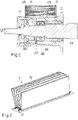
- Fig. 2 shows a sectional view of a first embodiment of the bearing housing 115 according to the invention for receiving the drive end 111 of the shaft 110 of the flow machine 100.
- the bearing housing 115 comprises a bearing axis LA and a bearing chamber 200 for receiving a bearing 116 and a lubricant chamber 202 arranged at the bearing chamber 200 for receiving a lubricant.
- the bearing chamber 200 is in fluid communication with the lubricant chamber 202 via an opening 222 such that the lubricant can flow between the bearing chamber 200 and the lubricant chamber 202.
- the bearing housing 115 comprises a wall portion 215 with a cooling fin 10 for dissipating a heat of the lubricant to an environment.
- the cooling fin 10 comprises a conduit 11 through which the lubricant can be conducted from the lubricant chamber 202 into the bearing chamber 200.
- the lubricant chamber 202 and the bearing chamber 200 are in fluid communication through the conduit 11.
- the cooling fin 10 is arranged on an outer surface 216 of the wall portion 215, which outer surface 216 is directed towards the environment.
- the outer surface 216 can be pressurized with a fluid such as water or air, for example via a fan.
- the cooling fin 10 extends in the direction of the bearing axis LA and from the outer surface 216 in a perpendicular direction to the bearing axis LA.
- the cooling fin could extend in a circumferential direction with respect to the bearing axis LA.
- the cooling fin 10 is detachably arranged on the bearing housing 115.
- the cooling fin 10 can in particular be screwed to the bearing housing 115.
- the conduit 11 is arranged meandering in the cooling fin such that a majority of a volume of the cooling fin 10 is filled through the conduit 11.
- Fig. 3 shows a perspective view of an embodiment of a fin stack 1 according to the invention.
- the fin stack 1 comprises a plurality of cooling fins which are arranged on a plate 12, which plate 12 can be attached to the outer surface 216 of the bearing housing 115. Therefore, the fin stack can be detachably arranged on the bearing housing 115.
- Fig. 4 shows a sectional view of a second embodiment of the bearing housing 115 according to the invention.
- the bearing housing 115 comprises a plurality of fin stacks 1 with a plurality of cooling fins 10.
- the fin stacks are detachably arranged on the bearing housing 115.
- the fin stacks 10 are therefore removable and can be constructed via additive manufacturing.
- the removable fin stacks 1 allow a changing of the cooling fins to suit a bearing heat load and environmental conditions.
- the plurality of cooling fins can be increased (attached) by attaching fin stacks with a higher number of cooling fins, thereby providing a bigger surface for heat exchange. This increases the flexibility of the system.
- a conveying wheel 230 is arranged in the lubricant chamber 202 and is connected to the shaft 110 in a rotationally fixed manner. If the shaft 10 is rotating in the operating state of the pump the conveying wheel 230 is rotating as well.
- a spiral housing 232 arranged around the conveying wheel 230 for discharging a flow of the lubricant to the cooling fin 10 which flow is generatable by the conveying wheel 230.
- Spiral housing 232 (also known as volute casing) is designed to guide the flow out of the conveying wheel 230 in order to convert the lubricants flow's kinetic energy into static pressure; it serves to collect the fluid discharged from the conveying wheel 230 and route it to a discharge nozzle 231 into the entry 16 of the conduits 10.
- the conveying wheel 230 and the spiral housing 232 thereby create forced lubricant circulation, such that the lubricant can be guide from the lubricant chamber through the conduit 11 in the cooling fins 10 to the bearing housing (and through the opening back to the lubricant chamber).
- Fig. 5 shows a sectional view of an embodiment of the cooling fins 10.
- the conduit 11 of the cooling fin 10 is arranged in the inside of the cooling fin.
- the conduit 11 thereby comprises a cooling chamber 13, which cooling chamber 13 is a reservoir in the conduit 11 that increases the cooling efficiency.
- the cooling chamber 13 can have any suitable shape and can be designed in different ways depending on the application.
Landscapes
- Engineering & Computer Science (AREA)
- General Engineering & Computer Science (AREA)
- Mechanical Engineering (AREA)
- Physics & Mathematics (AREA)
- Thermal Sciences (AREA)
- Fluid Mechanics (AREA)
- Structures Of Non-Positive Displacement Pumps (AREA)
- Mounting Of Bearings Or Others (AREA)
Abstract
Description
- The invention relates to a bearing housing for a flow machine according to the preamble of the
independent claim 1. The invention further relates to a flow machine with a bearing housing according to theindependent claim 11. - Flow machines for conveying a fluid, for example centrifugal pumps, compressors, fans, expanders or turbines typically comprise a stationary machine housing that encloses a rotor, e.g. an impeller, which is arranged on a shaft rotating around an axis of the flow machine. The flow machine also has at least one bearing unit with a radial and / or axial (thrust) bearing to support the shaft and the rotor. Typically, the bearing unit has a separate bearing housing that is firmly connected to the housing of the flow machine. In this case, the bearing housing comprises a bearing axis, a bearing chamber for receiving the bearing and a lubricant chamber for receiving a lubricant. The lubricant chamber and the bearing chamber are in fluid communication via an opening, so that the bearing can be cooled and lubricated by means of the lubricant during operation of the flow machine. Furthermore, the lubricant chamber has a wall portion for dissipating heat to the environment, wherein the wall portion has both an inner surface directed towards the lubricant chamber and an outer surface directed towards the environment.
- In order to dissipate the frictional heat generated in the bearing during operation of the flow machine, cooling fins are not required but are typically included to increase the surface area of the housing and therefore the overall cooling capacity. These cooling fins are part of the housing and not a separate item. In another way, cooling can also be achieved by water or by increasing the size of the lubricant chamber and/or by increasing the amount of lubricant. The current methods cool the housing itself and the lubricant is only cooled indirectly through being in contact with the housing. This is very inefficient and limits the maximum heat dissipation across the bearings.
- However, it has been shown in practice, that under certain operating conditions, for example high outside air temperatures, the cooling techniques mentioned are insufficient and expensive, resulting in an increased wear or even bearing failure or high bearing housing costs.
- Accordingly, it is an object of the invention to improve a bearing housing in such a way that sufficient cooling of the bearing and the lubricant can be achieved even at high ambient temperatures and high product temperatures, and thus the ambient temperature range for the operation of the flow machine can be extended, the operating range can be increased (e.g. running speed) and in particular to enlarge the maximum heat dissipation across the bearing.
- The objects of the invention meeting this problem are characterized by the features of the
independent claim 1 and ofindependent claim 11. - The dependent claims relate to particularly advantageous embodiments of the invention.
- Thus, the invention relates to a bearing housing for a flow machine, wherein the bearing housing comprises a bearing chamber for receiving a bearing and a lubricant chamber arranged at the bearing chamber for receiving a lubricant. The bearing chamber is in fluid communication with the lubricant chamber via an opening such that the lubricant can flow between the bearing chamber and the lubricant chamber. Furthermore, the bearing housing comprises a wall portion with a cooling fin for dissipating a heat of the lubricant to an environment.
- According to the invention, the cooling fin comprises a conduit for the lubricant through which conduit the lubricant chamber and the bearing chamber are in fluid communication such that the lubricant can be conducted from the lubricant chamber into the bearing chamber through the conduit to dissipate heat to the environment.
- Therefore, the bearing housing according to the invention has a cooling fin, which cooling fin increases the total surface area of the bearing housing, which increases the heat exchange with the environment as the heat of the lubricant can be more effectively transferred to the environment through the lubricant flowing through the cooling fin, since the heat exchange between the lubricant and the wall portion for the dissipation of heat to the environment is increased.
- This makes it possible to achieve sufficient cooling of the bearing and the lubricant even at high ambient temperatures and thus to expand the ambient temperature range for the operation of the flow machine. This ensures sufficient lubrication and cooling even at outside air temperatures above 50°C, which can increase the service life of the bearing.
- Therefore, in the operating state, the lubricant flows through the conduit in the cooling fin and is thereby directly cooled by the cooling fin and not only indirectly through being in contact with the bearing housing of the lubricant chamber. This is very efficient and enlarges the maximum heat dissipation across the bearing housing.
- In order to increase the heat dissipation, the conduit is preferably arranged meandering in the cooling fin such that a majority of a volume of the cooling fin is filled through the conduit. The more windings the conduit comprises and the more volume the conduit takes up in the cooling fin, the more effectively the heat can be released into the environment. In particular the majority of the volume of the cooling fin is 50 to 90 %, especially 60 to 80 % of the volume of the cooling fin.
- In a preferred embodiment, the cooling fin is arranged on an outer surface of the wall portion (external cooling fin), which outer surface is directed towards the environment.
- Alternatively, the lubricant chamber is filled with the lubricant up to a lubricant level in the operating state and the cooling fin is designed as internal cooling fin extending inside the lubricant chamber preferably completely below the lubricant level.
- In practice the bearing housing can comprise external and internal cooling fins. This increases the overall surface area available for heat exchange between the bearing housing and the environment.
- Furthermore, the cooling fin can comprise a cooling conduit through which cooling conduit a cooling fluid is flowable to additionally cool the lubricant which is flowable through the conduit.
- The lubricant can be guided from the lubricant chamber through the conduit in the cooling fins to the bearing housing (and through the opening back to the lubricant chamber or directly to the bearing) via a forced oil circulation. It has proven to be advantageous if the opening is formed as a slot. This results in an improved supply of lubricant from the bearing chamber into the lubricant chamber and an enlarged lubricant circulation. Preferably, the slot extends in the direction of the bearing axis.
- According to a preferred embodiment the bearing housing can comprise a bearing axis, wherein the cooling fin extends in the direction of the bearing axis and / or wherein the cooling fin extends in a circumferential direction with respect to the bearing axis. Thereby, the cooling fin can extend from the outer surface in a vertical direction to the bearing axis. This simplifies the production of the bearing housing. In addition, it is also possible, that the cooling fin extends spirally with respect to the bearing axis.
- In practice the cooling fin can be designed in such a way that it has a substantially rectangular cross-sectional area in a section perpendicular to the bearing axis. Furthermore, the bearing housing can comprise a plurality of cooling fins. In addition, the cooling fins can be designed as fin stack, which comprises a plurality of cooling fins. Of course, the bearing housing can also comprise a plurality of fin stacks.
- In a very advantageous embodiment, the cooling fin is detachably arranged on the bearing housing, in particular is detachably screwed to the bearing housing. The cooling fin is therefore removable and can be constructed via additive manufacturing or traditional methods. The removable cooling fins allows changing of the cooling fins to suit bearing heat load and environmental conditions. For example, the plurality of cooling fins can be increased (attached) by a settable number of cooling fins if there is a high bearing heat load and the plurality of cooling fins can be decreased (removed) by a settable number of cooling fins if there is a lower bearing heat load. This increases the flexibility of the system. In an embodiment according to the invention, the cooling fins can be arranged parallel to each other.
- In practice the conduit can be designed in different ways. For example, the conduit can comprise a cooling chamber, which cooling chamber corresponds to a reservoir in the conduit that can increase cooling efficiency. Furthermore, the conduit can include a plurality of windings. The conduit can be arranged inside the cooling fins and / or on a surface of the cooling fins. If the conduit is arranged on the surface of the cooling fins, the conduit is preferably arranged meandering on the surface such that a majority of the surface is cover by the conduit. In particular the majority of the surface is 50 to 90 %, especially 60 to 80 % of the surface of the cooling fin.
- The invention also relates to a flow machine with the bearing housing according to the invention. Here, the flow machine may be a pump, in particular a centrifugal pump. Preferably, the flow machine comprises the bearing arranged in the bearing chamber and a shaft rotatably mounted in the bearing. In a preferred embodiment, a conveying wheel is arranged in the lubricant chamber and is connected to the shaft in a rotationally fixed manner for guiding the lubricant through the conduit.
- In practice the flow machine can comprise a spiral housing arranged in the bearing housing, which spiral housing is arranged around the conveying wheel for discharging a flow of the lubricant to the cooling fin which flow is generatable by the conveying wheel.
- Further advantages, features and details of the invention result from the following description of embodiments and with reference to the drawings, in which identical or functionally identical elements are referred to with the same reference signs.
- There are shown:
- Fig. 1
- a sectional view of an embodiment of a flow machine according to the invention,
- Fig. 2
- a sectional view of a bearing housing according to the invention,
- Fig. 3
- a perspective view of an embodiment of fin stack according to the invention,
- Fig. 4
- a sectional view of a second embodiment of a bearing housing according to the invention;
- Fig. 5
- a sectional view of a fin stack with a cooling chamber.
- In the following description, reference is made by way of example to an important application, namely that the flow machine is designed as a centrifugal pump.
-
Fig. 1 shows a sectional view of an embodiment of a flow machine according to the invention, which is referred to in its unit with thereference sign 100. The embodiment of theflow machine 100 is acentrifugal pump 100 for conveying a fluid, for example water or crude oil or a multiphase liquid. It is clear, that the invention is neither limited to thecentrifugal pump 100 shown inFig. 1 , nor to centrifugal pumps as such, but it refers to flowmachines 100 in general. For example, theflow machine 100 may also be another type of pump, a compressor, a fan, an expander or a turbine. - The
centrifugal pump 100 comprises ahousing 101, which may consist of a plurality of housing parts, which are connected to each other to form thehousing 101. Thehousing 101 of thecentrifugal pump 100 comprises aninlet 102, through which the fluid to be conveyed enters thepump 100 and anoutlet 103 for discharging the fluid. At least oneimpeller 104 is provided inside thehousing 101 to convey the fluid. The centrifugal pump illustrated inFig. 1 is designed as a multi-stage pump withseveral impellers 104, here fiveimpellers 104. Allimpellers 104 are arranged in a row on ashaft 110 in a torque-proof manner. During operation of the pump, theimpellers 104 are rotated by means of theshaft 110 about an axial direction A, which is defined by the longitudinal axis of theshaft 110. The flow of the fluid is indicated inFig. 1 by the arrows without a reference sign. - The
shaft 110 is driven by means of a drive unit, not shown here, for example, an electric motor or any other motor, to which theshaft 110 is coupled. The end of theshaft 110 coupled to the drive unit is referred to as thedrive end 111 of the shaft, while the other end of theshaft 110 is referred to as thenon-drive end 112. According to the illustration inFig. 1 , thedrive end 110 connected to the drive unit (not shown) is on the left side. - The
pump 100 comprises the following components starting from thedrive end 111 of theshaft 110 and to the direction of the non-drive end 112: a driveend bearing housing 115 receiving a radial (or bearing journal) bearing 116; amechanical sealing 117 for sealing thepump 100 against leakage of the fluid along theshaft 110; the plurality of theimpellers 104; arelief piston 118 for compensating the axial thrust generated by theimpellers 104; another mechanical sealing 119 for sealing the non-drive side of theshaft 110 against leakage of the fluid to be conveyed; and a non-driveend bearing housing 1 receiving another radial (or journal-shaped) bearing 120, and a thrust (or axial) bearing 121 for supporting thenon-drive end 112 of theshaft 110 with respect to the radial direction and the axial direction A. - Thus, the
centrifugal pump 100 is provided withbearings impellers 104, in this example at thedrive end 111 of theshaft 110 and at thenon-drive end 112 of theshaft 110. - The bearing
housing 115 arranged at thedrive end 111 of theshaft 110 is designed according to the invention. Of course, the bearing housing according to the invention may also be provided at thenon-drive end 112 or also at both ends of thecentrifugal pump 100, i.e. at thedrive end 111 and at thenon-drive end 112. - The
centrifugal pump 100 according toFig. 1 has a thrust (or axial) bearing 121 as mentioned above. The bearing housing according to the invention is also particularly suitable for pumps without a thrust (or axial) bearing. These pumps have a two-part relief device instead of the relief piston 118 (Fig. 1 ) for axial thrust compensation comprising a co-rotating relief disc and a fixed relief counter-disc, which form a gap extending in the radial direction, through which gap a part of the fluid being under pressure in the pump is discharged to the outside. In doing so, the shaft of the pump is kept in a state of equilibrium in the axial direction between the force generated by the axial thrust and the counterforce generated by the relief device. In contrast to therelief piston 118, the relief device is "self-regulating" and compensates the entire axial thrust, so that no separate axial bearing is required at the pump. - The bearing
housing 115 will now be explained in more detail with reference to an embodiment of the bearinghousing 115 for receiving thedrive end 111 of theshaft 110. -
Fig. 2 shows a sectional view of a first embodiment of the bearinghousing 115 according to the invention for receiving thedrive end 111 of theshaft 110 of theflow machine 100. The bearinghousing 115 comprises a bearing axis LA and abearing chamber 200 for receiving abearing 116 and alubricant chamber 202 arranged at thebearing chamber 200 for receiving a lubricant. The bearingchamber 200 is in fluid communication with thelubricant chamber 202 via anopening 222 such that the lubricant can flow between thebearing chamber 200 and thelubricant chamber 202. Furthermore, the bearinghousing 115 comprises awall portion 215 with a coolingfin 10 for dissipating a heat of the lubricant to an environment. For effectively dissipating the heat of the lubricant to the environment the coolingfin 10 comprises aconduit 11 through which the lubricant can be conducted from thelubricant chamber 202 into the bearingchamber 200. Thelubricant chamber 202 and thebearing chamber 200 are in fluid communication through theconduit 11. - The cooling
fin 10 is arranged on anouter surface 216 of thewall portion 215, whichouter surface 216 is directed towards the environment. In order to achieve better cooling, theouter surface 216 can be pressurized with a fluid such as water or air, for example via a fan. - The cooling
fin 10 extends in the direction of the bearing axis LA and from theouter surface 216 in a perpendicular direction to the bearing axis LA. Alternatively, the cooling fin could extend in a circumferential direction with respect to the bearing axis LA. - The cooling
fin 10 is detachably arranged on the bearinghousing 115. The coolingfin 10 can in particular be screwed to the bearinghousing 115. - In order to increase the heat dissipation, the
conduit 11 is arranged meandering in the cooling fin such that a majority of a volume of the coolingfin 10 is filled through theconduit 11. The more windings theconduit 11 comprises and the more volume theconduit 11 takes up in the coolingfin 10, the more effectively the heat can be released into the environment. Therefore, 50 to 90 %, in particular 60 to 80 % of the volume of the coolingfin 10 are filled with theconduit 11. -
Fig. 3 shows a perspective view of an embodiment of afin stack 1 according to the invention. - The
fin stack 1 comprises a plurality of cooling fins which are arranged on aplate 12, whichplate 12 can be attached to theouter surface 216 of the bearinghousing 115. Therefore, the fin stack can be detachably arranged on the bearinghousing 115. -
Fig. 4 shows a sectional view of a second embodiment of the bearinghousing 115 according to the invention. - The bearing
housing 115 comprises a plurality offin stacks 1 with a plurality of coolingfins 10. The fin stacks are detachably arranged on the bearinghousing 115. The fin stacks 10 are therefore removable and can be constructed via additive manufacturing. Theremovable fin stacks 1 allow a changing of the cooling fins to suit a bearing heat load and environmental conditions. For example, the plurality of cooling fins can be increased (attached) by attaching fin stacks with a higher number of cooling fins, thereby providing a bigger surface for heat exchange. This increases the flexibility of the system. - A conveying
wheel 230 is arranged in thelubricant chamber 202 and is connected to theshaft 110 in a rotationally fixed manner. If theshaft 10 is rotating in the operating state of the pump the conveyingwheel 230 is rotating as well. Aspiral housing 232 arranged around the conveyingwheel 230 for discharging a flow of the lubricant to the coolingfin 10 which flow is generatable by the conveyingwheel 230. - Spiral housing 232 (also known as volute casing) is designed to guide the flow out of the conveying
wheel 230 in order to convert the lubricants flow's kinetic energy into static pressure; it serves to collect the fluid discharged from the conveyingwheel 230 and route it to adischarge nozzle 231 into theentry 16 of theconduits 10. The conveyingwheel 230 and thespiral housing 232 thereby create forced lubricant circulation, such that the lubricant can be guide from the lubricant chamber through theconduit 11 in the coolingfins 10 to the bearing housing (and through the opening back to the lubricant chamber). -
Fig. 5 shows a sectional view of an embodiment of the coolingfins 10. Theconduit 11 of the coolingfin 10 is arranged in the inside of the cooling fin. Theconduit 11 thereby comprises a coolingchamber 13, which coolingchamber 13 is a reservoir in theconduit 11 that increases the cooling efficiency. The coolingchamber 13 can have any suitable shape and can be designed in different ways depending on the application.
Claims (15)
- A bearing housing for a flow machine (100), wherein the bearing housing (115) comprises a bearing chamber (200) for receiving a bearing (116) and a lubricant chamber (202) arranged at the bearing chamber (200) for receiving a lubricant, and the bearing chamber (200) is in fluid communication with the lubricant chamber (202) via an opening (222) such that the lubricant can flow between the bearing chamber (200) and the lubricant chamber (202), the bearing housing (200) comprising a wall portion (215) with a cooling fin (10) for dissipating a heat of the lubricant to an environment, characterized in that the cooling fin (10) comprises a conduit (11) for the lubricant through which conduit (11) the lubricant chamber (202) and the bearing chamber (200) are in fluid communication such that the lubricant can be conducted from the lubricant chamber (202) into the bearing chamber (200) through the conduit (11) to dissipate the heat to the environment.
- A bearing housing according to claim 1, wherein the cooling fin (10) is arranged on an outer surface (216) of the wall portion (215), which outer surface (216) is directed towards the environment.
- A bearing housing according to claim 1 or 2, wherein the conduit (11) is arranged meandering in the cooling fin (10) such that a majority of a volume of the cooling fin (10) is filled through the conduit (11).
- A bearing housing according to one of the preceding claims comprising a bearing axis (LA), wherein the cooling fin (10) extends in the direction of the bearing axis (LA) and / or wherein the cooling fin (10) extends in a circumferential direction with respect to the bearing axis (LA).
- A bearing housing according to claim 4, wherein the cooling fin (10) extends from the outer surface (216) in a vertical direction to the bearing axis (LA).
- A bearing housing according to one of the preceding claims, wherein the cooling fin (10) is designed in such a way that it has a substantially rectangular cross-sectional area in a section perpendicular to the bearing axis (LA).
- A bearing housing according to one of the preceding claims, wherein the cooling fin (10) is detachably arranged on the bearing housing (115), in particular is detachably screwed to the bearing housing (115).
- A bearing housing according to one of the preceding claims, wherein the conduit (11) comprises a cooling chamber (13).
- A bearing housing according to one of the preceding claims comprising a plurality of cooling fins (10).
- A bearing housing according to claim 9, wherein the cooling fins (10) are arranged parallel to each other.
- A flow machine with a bearing housing (115) according to anyone of the claims 1 to 10.
- A flow machine according to claim 11, wherein the flow machine (100) is a pump (100), in particular a centrifugal pump (100).
- A flow machine according to claim 11 or 12 comprising the bearing (116) arranged in the bearing chamber (200) and a shaft (110) rotatably mounted in the bearing (116).
- A flow machine according to claim 13, wherein a conveying wheel (230) is arranged in the lubricant chamber (202) and is connected to the shaft (110) in a rotationally fixed manner for guiding the lubricant through the conduit (11).
- A flow machine according to claim 14 comprising a spiral housing (231) arranged in the bearing housing (115), which spiral housing (231) is arranged around the conveying wheel (230) for discharging a flow of the lubricant to the cooling fin (10) which flow is generatable by the conveying wheel (230).
Priority Applications (1)
| Application Number | Priority Date | Filing Date | Title |
|---|---|---|---|
| EP20213791.5A EP4012211B1 (en) | 2020-12-14 | 2020-12-14 | A bearing housing for a flow machine and a flow machine with a bearing housing |
Applications Claiming Priority (1)
| Application Number | Priority Date | Filing Date | Title |
|---|---|---|---|
| EP20213791.5A EP4012211B1 (en) | 2020-12-14 | 2020-12-14 | A bearing housing for a flow machine and a flow machine with a bearing housing |
Publications (2)
| Publication Number | Publication Date |
|---|---|
| EP4012211A1 true EP4012211A1 (en) | 2022-06-15 |
| EP4012211B1 EP4012211B1 (en) | 2023-10-18 |
Family
ID=73835429
Family Applications (1)
| Application Number | Title | Priority Date | Filing Date |
|---|---|---|---|
| EP20213791.5A Active EP4012211B1 (en) | 2020-12-14 | 2020-12-14 | A bearing housing for a flow machine and a flow machine with a bearing housing |
Country Status (1)
| Country | Link |
|---|---|
| EP (1) | EP4012211B1 (en) |
Cited By (1)
| Publication number | Priority date | Publication date | Assignee | Title |
|---|---|---|---|---|
| CN121402566A (en) * | 2025-12-27 | 2026-01-27 | 山东邦德重工科技有限公司 | A lightweight press with bearing air cooling function |
Citations (7)
| Publication number | Priority date | Publication date | Assignee | Title |
|---|---|---|---|---|
| US2352206A (en) * | 1942-02-07 | 1944-06-27 | George H Kendall | Controlled temperature bearing |
| DE961584C (en) * | 1941-07-25 | 1957-04-11 | Siemens Ag | Oil-cooled shaft bearings, especially plain bearings |
| FR2546605A1 (en) * | 1983-05-28 | 1984-11-30 | Klein Schanzlin & Becker Ag | OIL SUPPLYING DEVICE OF TREE BEARING SUBJECTED TO HIGH THERMAL SOLLICITATION |
| EP0235505A2 (en) * | 1986-03-03 | 1987-09-09 | TEIJIN SEIKI CO. Ltd. | Bearing cooling apparatus of heating roller |
| CN205071563U (en) * | 2015-07-03 | 2016-03-02 | 浙江嘉熙光电设备制造有限公司 | Superconductive gilled radiator of heat |
| WO2019002358A1 (en) * | 2017-06-28 | 2019-01-03 | Sulzer Management Ag | BEARING CASE FOR A FLOW MACHINE, AS WELL AS A FLOW MACHINE WITH A STORAGE CASE |
| EP3730796A1 (en) * | 2019-04-23 | 2020-10-28 | Sulzer Management AG | Centrifugal pump |
-
2020
- 2020-12-14 EP EP20213791.5A patent/EP4012211B1/en active Active
Patent Citations (7)
| Publication number | Priority date | Publication date | Assignee | Title |
|---|---|---|---|---|
| DE961584C (en) * | 1941-07-25 | 1957-04-11 | Siemens Ag | Oil-cooled shaft bearings, especially plain bearings |
| US2352206A (en) * | 1942-02-07 | 1944-06-27 | George H Kendall | Controlled temperature bearing |
| FR2546605A1 (en) * | 1983-05-28 | 1984-11-30 | Klein Schanzlin & Becker Ag | OIL SUPPLYING DEVICE OF TREE BEARING SUBJECTED TO HIGH THERMAL SOLLICITATION |
| EP0235505A2 (en) * | 1986-03-03 | 1987-09-09 | TEIJIN SEIKI CO. Ltd. | Bearing cooling apparatus of heating roller |
| CN205071563U (en) * | 2015-07-03 | 2016-03-02 | 浙江嘉熙光电设备制造有限公司 | Superconductive gilled radiator of heat |
| WO2019002358A1 (en) * | 2017-06-28 | 2019-01-03 | Sulzer Management Ag | BEARING CASE FOR A FLOW MACHINE, AS WELL AS A FLOW MACHINE WITH A STORAGE CASE |
| EP3730796A1 (en) * | 2019-04-23 | 2020-10-28 | Sulzer Management AG | Centrifugal pump |
Cited By (1)
| Publication number | Priority date | Publication date | Assignee | Title |
|---|---|---|---|---|
| CN121402566A (en) * | 2025-12-27 | 2026-01-27 | 山东邦德重工科技有限公司 | A lightweight press with bearing air cooling function |
Also Published As
| Publication number | Publication date |
|---|---|
| EP4012211B1 (en) | 2023-10-18 |
Similar Documents
| Publication | Publication Date | Title |
|---|---|---|
| US20200173496A1 (en) | Bearing housing for a turbomachine, and turbomachine having a bearing housing | |
| US6997686B2 (en) | Motor driven two-stage centrifugal air-conditioning compressor | |
| US5494413A (en) | High speed fluid pump powered by an integral canned electrical motor | |
| US10030672B2 (en) | Method and system for cooling a motor-compressor with a closed-loop cooling circuit | |
| US11754086B2 (en) | Bearing housing for a flow machine and a flow machine with a bearing housing | |
| EP3401549B1 (en) | Turbo compressor | |
| EP3450701B1 (en) | Turbomachine systems with magnetic bearing | |
| US20130129488A1 (en) | Foil bearing supported motor-driven blower | |
| US20150064026A1 (en) | Motor cooling system manifold | |
| US12234838B2 (en) | Turbo compressor comprising bearing cooling channel | |
| CN105626540B (en) | Sectional multi-stage centrifugal pump | |
| US20070212238A1 (en) | Rotodynamic Fluid Machine | |
| EP4012211B1 (en) | A bearing housing for a flow machine and a flow machine with a bearing housing | |
| CN117780663A (en) | Centrifugal compressors and refrigeration equipment | |
| CN101248280B (en) | Electric motor having a coaxially associated pump | |
| CA2382739C (en) | Pressurized bearing system for submersible motor | |
| KR100530692B1 (en) | Turbo machine | |
| CN113286947B (en) | Pump with bearing lubrication system | |
| EP3303776B1 (en) | Combined bearing and turbomachine including said bearing | |
| GB2187797A (en) | Turbocharger | |
| CN117083451A (en) | Supercharger | |
| CN116867975B (en) | Turbine compressor including bearing cooling passages |
Legal Events
| Date | Code | Title | Description |
|---|---|---|---|
| PUAI | Public reference made under article 153(3) epc to a published international application that has entered the european phase |
Free format text: ORIGINAL CODE: 0009012 |
|
| STAA | Information on the status of an ep patent application or granted ep patent |
Free format text: STATUS: THE APPLICATION HAS BEEN PUBLISHED |
|
| AK | Designated contracting states |
Kind code of ref document: A1 Designated state(s): AL AT BE BG CH CY CZ DE DK EE ES FI FR GB GR HR HU IE IS IT LI LT LU LV MC MK MT NL NO PL PT RO RS SE SI SK SM TR |
|
| STAA | Information on the status of an ep patent application or granted ep patent |
Free format text: STATUS: REQUEST FOR EXAMINATION WAS MADE |
|
| 17P | Request for examination filed |
Effective date: 20221215 |
|
| RBV | Designated contracting states (corrected) |
Designated state(s): AL AT BE BG CH CY CZ DE DK EE ES FI FR GB GR HR HU IE IS IT LI LT LU LV MC MK MT NL NO PL PT RO RS SE SI SK SM TR |
|
| GRAP | Despatch of communication of intention to grant a patent |
Free format text: ORIGINAL CODE: EPIDOSNIGR1 |
|
| STAA | Information on the status of an ep patent application or granted ep patent |
Free format text: STATUS: GRANT OF PATENT IS INTENDED |
|
| RIC1 | Information provided on ipc code assigned before grant |
Ipc: F04D 29/047 20060101ALI20230504BHEP Ipc: F04D 1/06 20060101ALI20230504BHEP Ipc: F04D 29/58 20060101ALI20230504BHEP Ipc: F04D 29/06 20060101ALI20230504BHEP Ipc: F04D 29/046 20060101ALI20230504BHEP Ipc: F16C 35/04 20060101ALI20230504BHEP Ipc: F16C 33/66 20060101ALI20230504BHEP Ipc: F16C 37/00 20060101AFI20230504BHEP |
|
| INTG | Intention to grant announced |
Effective date: 20230525 |
|
| GRAS | Grant fee paid |
Free format text: ORIGINAL CODE: EPIDOSNIGR3 |
|
| GRAA | (expected) grant |
Free format text: ORIGINAL CODE: 0009210 |
|
| STAA | Information on the status of an ep patent application or granted ep patent |
Free format text: STATUS: THE PATENT HAS BEEN GRANTED |
|
| P01 | Opt-out of the competence of the unified patent court (upc) registered |
Effective date: 20230830 |
|
| AK | Designated contracting states |
Kind code of ref document: B1 Designated state(s): AL AT BE BG CH CY CZ DE DK EE ES FI FR GB GR HR HU IE IS IT LI LT LU LV MC MK MT NL NO PL PT RO RS SE SI SK SM TR |
|
| REG | Reference to a national code |
Ref country code: GB Ref legal event code: FG4D |
|
| REG | Reference to a national code |
Ref country code: CH Ref legal event code: EP |
|
| REG | Reference to a national code |
Ref country code: IE Ref legal event code: FG4D |
|
| REG | Reference to a national code |
Ref country code: DE Ref legal event code: R096 Ref document number: 602020019392 Country of ref document: DE |
|
| REG | Reference to a national code |
Ref country code: NO Ref legal event code: T2 Effective date: 20231018 |
|
| REG | Reference to a national code |
Ref country code: LT Ref legal event code: MG9D |
|
| REG | Reference to a national code |
Ref country code: NL Ref legal event code: MP Effective date: 20231018 |
|
| REG | Reference to a national code |
Ref country code: AT Ref legal event code: MK05 Ref document number: 1622719 Country of ref document: AT Kind code of ref document: T Effective date: 20231018 |
|
| PG25 | Lapsed in a contracting state [announced via postgrant information from national office to epo] |
Ref country code: NL Free format text: LAPSE BECAUSE OF FAILURE TO SUBMIT A TRANSLATION OF THE DESCRIPTION OR TO PAY THE FEE WITHIN THE PRESCRIBED TIME-LIMIT Effective date: 20231018 |
|
| PG25 | Lapsed in a contracting state [announced via postgrant information from national office to epo] |
Ref country code: GR Free format text: LAPSE BECAUSE OF FAILURE TO SUBMIT A TRANSLATION OF THE DESCRIPTION OR TO PAY THE FEE WITHIN THE PRESCRIBED TIME-LIMIT Effective date: 20240119 |
|
| PG25 | Lapsed in a contracting state [announced via postgrant information from national office to epo] |
Ref country code: IS Free format text: LAPSE BECAUSE OF FAILURE TO SUBMIT A TRANSLATION OF THE DESCRIPTION OR TO PAY THE FEE WITHIN THE PRESCRIBED TIME-LIMIT Effective date: 20240218 |
|
| PG25 | Lapsed in a contracting state [announced via postgrant information from national office to epo] |
Ref country code: LT Free format text: LAPSE BECAUSE OF FAILURE TO SUBMIT A TRANSLATION OF THE DESCRIPTION OR TO PAY THE FEE WITHIN THE PRESCRIBED TIME-LIMIT Effective date: 20231018 |
|
| PG25 | Lapsed in a contracting state [announced via postgrant information from national office to epo] |
Ref country code: AT Free format text: LAPSE BECAUSE OF FAILURE TO SUBMIT A TRANSLATION OF THE DESCRIPTION OR TO PAY THE FEE WITHIN THE PRESCRIBED TIME-LIMIT Effective date: 20231018 |
|
| PG25 | Lapsed in a contracting state [announced via postgrant information from national office to epo] |
Ref country code: ES Free format text: LAPSE BECAUSE OF FAILURE TO SUBMIT A TRANSLATION OF THE DESCRIPTION OR TO PAY THE FEE WITHIN THE PRESCRIBED TIME-LIMIT Effective date: 20231018 |
|
| PG25 | Lapsed in a contracting state [announced via postgrant information from national office to epo] |
Ref country code: LT Free format text: LAPSE BECAUSE OF FAILURE TO SUBMIT A TRANSLATION OF THE DESCRIPTION OR TO PAY THE FEE WITHIN THE PRESCRIBED TIME-LIMIT Effective date: 20231018 Ref country code: IS Free format text: LAPSE BECAUSE OF FAILURE TO SUBMIT A TRANSLATION OF THE DESCRIPTION OR TO PAY THE FEE WITHIN THE PRESCRIBED TIME-LIMIT Effective date: 20240218 Ref country code: GR Free format text: LAPSE BECAUSE OF FAILURE TO SUBMIT A TRANSLATION OF THE DESCRIPTION OR TO PAY THE FEE WITHIN THE PRESCRIBED TIME-LIMIT Effective date: 20240119 Ref country code: ES Free format text: LAPSE BECAUSE OF FAILURE TO SUBMIT A TRANSLATION OF THE DESCRIPTION OR TO PAY THE FEE WITHIN THE PRESCRIBED TIME-LIMIT Effective date: 20231018 Ref country code: BG Free format text: LAPSE BECAUSE OF FAILURE TO SUBMIT A TRANSLATION OF THE DESCRIPTION OR TO PAY THE FEE WITHIN THE PRESCRIBED TIME-LIMIT Effective date: 20240118 Ref country code: AT Free format text: LAPSE BECAUSE OF FAILURE TO SUBMIT A TRANSLATION OF THE DESCRIPTION OR TO PAY THE FEE WITHIN THE PRESCRIBED TIME-LIMIT Effective date: 20231018 Ref country code: PT Free format text: LAPSE BECAUSE OF FAILURE TO SUBMIT A TRANSLATION OF THE DESCRIPTION OR TO PAY THE FEE WITHIN THE PRESCRIBED TIME-LIMIT Effective date: 20240219 |
|
| PG25 | Lapsed in a contracting state [announced via postgrant information from national office to epo] |
Ref country code: SE Free format text: LAPSE BECAUSE OF FAILURE TO SUBMIT A TRANSLATION OF THE DESCRIPTION OR TO PAY THE FEE WITHIN THE PRESCRIBED TIME-LIMIT Effective date: 20231018 Ref country code: RS Free format text: LAPSE BECAUSE OF FAILURE TO SUBMIT A TRANSLATION OF THE DESCRIPTION OR TO PAY THE FEE WITHIN THE PRESCRIBED TIME-LIMIT Effective date: 20231018 Ref country code: PL Free format text: LAPSE BECAUSE OF FAILURE TO SUBMIT A TRANSLATION OF THE DESCRIPTION OR TO PAY THE FEE WITHIN THE PRESCRIBED TIME-LIMIT Effective date: 20231018 Ref country code: LV Free format text: LAPSE BECAUSE OF FAILURE TO SUBMIT A TRANSLATION OF THE DESCRIPTION OR TO PAY THE FEE WITHIN THE PRESCRIBED TIME-LIMIT Effective date: 20231018 Ref country code: HR Free format text: LAPSE BECAUSE OF FAILURE TO SUBMIT A TRANSLATION OF THE DESCRIPTION OR TO PAY THE FEE WITHIN THE PRESCRIBED TIME-LIMIT Effective date: 20231018 |
|
| PG25 | Lapsed in a contracting state [announced via postgrant information from national office to epo] |
Ref country code: DK Free format text: LAPSE BECAUSE OF FAILURE TO SUBMIT A TRANSLATION OF THE DESCRIPTION OR TO PAY THE FEE WITHIN THE PRESCRIBED TIME-LIMIT Effective date: 20231018 |
|
| REG | Reference to a national code |
Ref country code: DE Ref legal event code: R097 Ref document number: 602020019392 Country of ref document: DE |
|
| PG25 | Lapsed in a contracting state [announced via postgrant information from national office to epo] |
Ref country code: CZ Free format text: LAPSE BECAUSE OF FAILURE TO SUBMIT A TRANSLATION OF THE DESCRIPTION OR TO PAY THE FEE WITHIN THE PRESCRIBED TIME-LIMIT Effective date: 20231018 |
|
| PG25 | Lapsed in a contracting state [announced via postgrant information from national office to epo] |
Ref country code: SK Free format text: LAPSE BECAUSE OF FAILURE TO SUBMIT A TRANSLATION OF THE DESCRIPTION OR TO PAY THE FEE WITHIN THE PRESCRIBED TIME-LIMIT Effective date: 20231018 |
|
| PG25 | Lapsed in a contracting state [announced via postgrant information from national office to epo] |
Ref country code: SM Free format text: LAPSE BECAUSE OF FAILURE TO SUBMIT A TRANSLATION OF THE DESCRIPTION OR TO PAY THE FEE WITHIN THE PRESCRIBED TIME-LIMIT Effective date: 20231018 Ref country code: SK Free format text: LAPSE BECAUSE OF FAILURE TO SUBMIT A TRANSLATION OF THE DESCRIPTION OR TO PAY THE FEE WITHIN THE PRESCRIBED TIME-LIMIT Effective date: 20231018 Ref country code: RO Free format text: LAPSE BECAUSE OF FAILURE TO SUBMIT A TRANSLATION OF THE DESCRIPTION OR TO PAY THE FEE WITHIN THE PRESCRIBED TIME-LIMIT Effective date: 20231018 Ref country code: IT Free format text: LAPSE BECAUSE OF FAILURE TO SUBMIT A TRANSLATION OF THE DESCRIPTION OR TO PAY THE FEE WITHIN THE PRESCRIBED TIME-LIMIT Effective date: 20231018 Ref country code: EE Free format text: LAPSE BECAUSE OF FAILURE TO SUBMIT A TRANSLATION OF THE DESCRIPTION OR TO PAY THE FEE WITHIN THE PRESCRIBED TIME-LIMIT Effective date: 20231018 Ref country code: DK Free format text: LAPSE BECAUSE OF FAILURE TO SUBMIT A TRANSLATION OF THE DESCRIPTION OR TO PAY THE FEE WITHIN THE PRESCRIBED TIME-LIMIT Effective date: 20231018 Ref country code: CZ Free format text: LAPSE BECAUSE OF FAILURE TO SUBMIT A TRANSLATION OF THE DESCRIPTION OR TO PAY THE FEE WITHIN THE PRESCRIBED TIME-LIMIT Effective date: 20231018 |
|
| REG | Reference to a national code |
Ref country code: CH Ref legal event code: PL |
|
| PLBE | No opposition filed within time limit |
Free format text: ORIGINAL CODE: 0009261 |
|
| STAA | Information on the status of an ep patent application or granted ep patent |
Free format text: STATUS: NO OPPOSITION FILED WITHIN TIME LIMIT |
|
| PG25 | Lapsed in a contracting state [announced via postgrant information from national office to epo] |
Ref country code: LU Free format text: LAPSE BECAUSE OF NON-PAYMENT OF DUE FEES Effective date: 20231214 |
|
| PG25 | Lapsed in a contracting state [announced via postgrant information from national office to epo] |
Ref country code: MC Free format text: LAPSE BECAUSE OF FAILURE TO SUBMIT A TRANSLATION OF THE DESCRIPTION OR TO PAY THE FEE WITHIN THE PRESCRIBED TIME-LIMIT Effective date: 20231018 |
|
| REG | Reference to a national code |
Ref country code: BE Ref legal event code: MM Effective date: 20231231 |
|
| PG25 | Lapsed in a contracting state [announced via postgrant information from national office to epo] |
Ref country code: MC Free format text: LAPSE BECAUSE OF FAILURE TO SUBMIT A TRANSLATION OF THE DESCRIPTION OR TO PAY THE FEE WITHIN THE PRESCRIBED TIME-LIMIT Effective date: 20231018 Ref country code: LU Free format text: LAPSE BECAUSE OF NON-PAYMENT OF DUE FEES Effective date: 20231214 |
|
| 26N | No opposition filed |
Effective date: 20240719 |
|
| REG | Reference to a national code |
Ref country code: IE Ref legal event code: MM4A |
|
| PG25 | Lapsed in a contracting state [announced via postgrant information from national office to epo] |
Ref country code: IE Free format text: LAPSE BECAUSE OF NON-PAYMENT OF DUE FEES Effective date: 20231214 |
|
| PG25 | Lapsed in a contracting state [announced via postgrant information from national office to epo] |
Ref country code: BE Free format text: LAPSE BECAUSE OF NON-PAYMENT OF DUE FEES Effective date: 20231231 |
|
| PG25 | Lapsed in a contracting state [announced via postgrant information from national office to epo] |
Ref country code: CH Free format text: LAPSE BECAUSE OF NON-PAYMENT OF DUE FEES Effective date: 20231231 |
|
| PG25 | Lapsed in a contracting state [announced via postgrant information from national office to epo] |
Ref country code: SI Free format text: LAPSE BECAUSE OF FAILURE TO SUBMIT A TRANSLATION OF THE DESCRIPTION OR TO PAY THE FEE WITHIN THE PRESCRIBED TIME-LIMIT Effective date: 20231018 |
|
| PG25 | Lapsed in a contracting state [announced via postgrant information from national office to epo] |
Ref country code: SI Free format text: LAPSE BECAUSE OF FAILURE TO SUBMIT A TRANSLATION OF THE DESCRIPTION OR TO PAY THE FEE WITHIN THE PRESCRIBED TIME-LIMIT Effective date: 20231018 Ref country code: IE Free format text: LAPSE BECAUSE OF NON-PAYMENT OF DUE FEES Effective date: 20231214 Ref country code: CH Free format text: LAPSE BECAUSE OF NON-PAYMENT OF DUE FEES Effective date: 20231231 Ref country code: BE Free format text: LAPSE BECAUSE OF NON-PAYMENT OF DUE FEES Effective date: 20231231 |
|
| PG25 | Lapsed in a contracting state [announced via postgrant information from national office to epo] |
Ref country code: FI Free format text: LAPSE BECAUSE OF FAILURE TO SUBMIT A TRANSLATION OF THE DESCRIPTION OR TO PAY THE FEE WITHIN THE PRESCRIBED TIME-LIMIT Effective date: 20231019 |
|
| PG25 | Lapsed in a contracting state [announced via postgrant information from national office to epo] |
Ref country code: CY Free format text: LAPSE BECAUSE OF FAILURE TO SUBMIT A TRANSLATION OF THE DESCRIPTION OR TO PAY THE FEE WITHIN THE PRESCRIBED TIME-LIMIT; INVALID AB INITIO Effective date: 20201214 |
|
| PG25 | Lapsed in a contracting state [announced via postgrant information from national office to epo] |
Ref country code: HU Free format text: LAPSE BECAUSE OF FAILURE TO SUBMIT A TRANSLATION OF THE DESCRIPTION OR TO PAY THE FEE WITHIN THE PRESCRIBED TIME-LIMIT; INVALID AB INITIO Effective date: 20201214 |
|
| PG25 | Lapsed in a contracting state [announced via postgrant information from national office to epo] |
Ref country code: TR Free format text: LAPSE BECAUSE OF FAILURE TO SUBMIT A TRANSLATION OF THE DESCRIPTION OR TO PAY THE FEE WITHIN THE PRESCRIBED TIME-LIMIT Effective date: 20231018 |
|
| PGFP | Annual fee paid to national office [announced via postgrant information from national office to epo] |
Ref country code: DE Payment date: 20251211 Year of fee payment: 6 |
|
| PGFP | Annual fee paid to national office [announced via postgrant information from national office to epo] |
Ref country code: GB Payment date: 20251219 Year of fee payment: 6 |
|
| PGFP | Annual fee paid to national office [announced via postgrant information from national office to epo] |
Ref country code: FR Payment date: 20251229 Year of fee payment: 6 |
|
| PGFP | Annual fee paid to national office [announced via postgrant information from national office to epo] |
Ref country code: NO Payment date: 20251230 Year of fee payment: 6 |