EP4012191A1 - Axial flow fan, and refrigeration cycle device - Google Patents
Axial flow fan, and refrigeration cycle device Download PDFInfo
- Publication number
- EP4012191A1 EP4012191A1 EP20852113.8A EP20852113A EP4012191A1 EP 4012191 A1 EP4012191 A1 EP 4012191A1 EP 20852113 A EP20852113 A EP 20852113A EP 4012191 A1 EP4012191 A1 EP 4012191A1
- Authority
- EP
- European Patent Office
- Prior art keywords
- reinforcing protrusion
- depression
- rotation direction
- axial fan
- virtual line
- Prior art date
- Legal status (The legal status is an assumption and is not a legal conclusion. Google has not performed a legal analysis and makes no representation as to the accuracy of the status listed.)
- Granted
Links
Images





Classifications
-
- F—MECHANICAL ENGINEERING; LIGHTING; HEATING; WEAPONS; BLASTING
- F04—POSITIVE - DISPLACEMENT MACHINES FOR LIQUIDS; PUMPS FOR LIQUIDS OR ELASTIC FLUIDS
- F04D—NON-POSITIVE-DISPLACEMENT PUMPS
- F04D29/00—Details, component parts, or accessories
- F04D29/26—Rotors specially for elastic fluids
- F04D29/32—Rotors specially for elastic fluids for axial flow pumps
- F04D29/38—Blades
- F04D29/384—Blades characterised by form
-
- F—MECHANICAL ENGINEERING; LIGHTING; HEATING; WEAPONS; BLASTING
- F04—POSITIVE - DISPLACEMENT MACHINES FOR LIQUIDS; PUMPS FOR LIQUIDS OR ELASTIC FLUIDS
- F04D—NON-POSITIVE-DISPLACEMENT PUMPS
- F04D29/00—Details, component parts, or accessories
- F04D29/26—Rotors specially for elastic fluids
- F04D29/32—Rotors specially for elastic fluids for axial flow pumps
- F04D29/38—Blades
-
- F—MECHANICAL ENGINEERING; LIGHTING; HEATING; WEAPONS; BLASTING
- F04—POSITIVE - DISPLACEMENT MACHINES FOR LIQUIDS; PUMPS FOR LIQUIDS OR ELASTIC FLUIDS
- F04D—NON-POSITIVE-DISPLACEMENT PUMPS
- F04D29/00—Details, component parts, or accessories
- F04D29/26—Rotors specially for elastic fluids
- F04D29/32—Rotors specially for elastic fluids for axial flow pumps
- F04D29/38—Blades
- F04D29/388—Blades characterised by construction
-
- F—MECHANICAL ENGINEERING; LIGHTING; HEATING; WEAPONS; BLASTING
- F04—POSITIVE - DISPLACEMENT MACHINES FOR LIQUIDS; PUMPS FOR LIQUIDS OR ELASTIC FLUIDS
- F04D—NON-POSITIVE-DISPLACEMENT PUMPS
- F04D29/00—Details, component parts, or accessories
- F04D29/66—Combating cavitation, whirls, noise, vibration or the like; Balancing
- F04D29/661—Combating cavitation, whirls, noise, vibration or the like; Balancing especially adapted for elastic fluid pumps
- F04D29/666—Combating cavitation, whirls, noise, vibration or the like; Balancing especially adapted for elastic fluid pumps by means of rotor construction or layout, e.g. unequal distribution of blades or vanes
-
- F—MECHANICAL ENGINEERING; LIGHTING; HEATING; WEAPONS; BLASTING
- F24—HEATING; RANGES; VENTILATING
- F24F—AIR-CONDITIONING; AIR-HUMIDIFICATION; VENTILATION; USE OF AIR CURRENTS FOR SCREENING
- F24F1/00—Room units for air-conditioning, e.g. separate or self-contained units or units receiving primary air from a central station
- F24F1/06—Separate outdoor units, e.g. outdoor unit to be linked to a separate room comprising a compressor and a heat exchanger
- F24F1/38—Fan details of outdoor units, e.g. bell-mouth shaped inlets or fan mountings
-
- F—MECHANICAL ENGINEERING; LIGHTING; HEATING; WEAPONS; BLASTING
- F24—HEATING; RANGES; VENTILATING
- F24F—AIR-CONDITIONING; AIR-HUMIDIFICATION; VENTILATION; USE OF AIR CURRENTS FOR SCREENING
- F24F1/00—Room units for air-conditioning, e.g. separate or self-contained units or units receiving primary air from a central station
- F24F1/06—Separate outdoor units, e.g. outdoor unit to be linked to a separate room comprising a compressor and a heat exchanger
- F24F1/40—Vibration or noise prevention at outdoor units
-
- F—MECHANICAL ENGINEERING; LIGHTING; HEATING; WEAPONS; BLASTING
- F05—INDEXING SCHEMES RELATING TO ENGINES OR PUMPS IN VARIOUS SUBCLASSES OF CLASSES F01-F04
- F05D—INDEXING SCHEME FOR ASPECTS RELATING TO NON-POSITIVE-DISPLACEMENT MACHINES OR ENGINES, GAS-TURBINES OR JET-PROPULSION PLANTS
- F05D2240/00—Components
- F05D2240/20—Rotors
- F05D2240/30—Characteristics of rotor blades, i.e. of any element transforming dynamic fluid energy to or from rotational energy and being attached to a rotor
- F05D2240/304—Characteristics of rotor blades, i.e. of any element transforming dynamic fluid energy to or from rotational energy and being attached to a rotor related to the trailing edge of a rotor blade
-
- F—MECHANICAL ENGINEERING; LIGHTING; HEATING; WEAPONS; BLASTING
- F05—INDEXING SCHEMES RELATING TO ENGINES OR PUMPS IN VARIOUS SUBCLASSES OF CLASSES F01-F04
- F05D—INDEXING SCHEME FOR ASPECTS RELATING TO NON-POSITIVE-DISPLACEMENT MACHINES OR ENGINES, GAS-TURBINES OR JET-PROPULSION PLANTS
- F05D2270/00—Control
- F05D2270/01—Purpose of the control system
- F05D2270/11—Purpose of the control system to prolong engine life
- F05D2270/114—Purpose of the control system to prolong engine life by limiting mechanical stresses
Definitions
- the present invention relates to an axial fan having a depression depressed in a rotation direction on a trailing edge of each blade, and a refrigeration cycle apparatus including the axial fan.
- Patent Literature 1 JP 2005-140081 A
- an axial fan including a depression in each blade (described as a rear edge concave portion in Patent Literature 1).
- the depression is provided on a trailing edge of each blade.
- centrifugal force generated by rotation of the blade causes force to be applied to the blade in a direction outward from a rotating shaft.
- a stress is concentrated around the depression. Therefore, in the axial fan including the depression, if the thickness of the blade is reduced in order to improve blast performance, damage is likely to occur around the depression.
- the axial fan including the depression in the blade has a problem of inhibiting damage to the blade having high blast performance.
- An axial fan is an axial fan rotating around a rotating shaft, and includes a hub and a plurality of blades extending in a radial direction from the hub.
- Each of the blades includes a leading edge located forward of a rotation direction and a trailing edge located rearward.
- the trailing edge includes a depression depressed forward of the rotation direction.
- Each of the blades includes a reinforcing protrusion located at least forwardmost of the rotation direction of the depression and having a wall thickness thicker than a surrounding portion.
- the reinforcing protrusion extends radially inside of the first virtual line and extends radially outside of the second virtual line, the first virtual line and the second virtual line respectively passing through a rearmost first endpoint of the rotation direction on a radially inside of a rear end that substantially overlaps the depression, and a rearmost second endpoint on a radially outside of the rear end.
- the axial fan according to the first aspect can reinforce surroundings of the depression of the blade. As a result, the axial fan can easily thin the blade and improve the blast performance.
- the axial fan according to a second aspect is the axial fan according to the first aspect, in which the wall thickness of a thickest portion of a place including the reinforcing protrusion of each of the blades is 1.5 times or less of the wall thickness of each of the blades in a thinnest portion around the reinforcing protrusion.
- the axial fan according to the second aspect can suppress the increase in noise caused by the reinforcing protrusion.
- the axial fan according to a third aspect is the axial fan according to the first aspect or second aspect, in which a height of the reinforcing protrusion from a pressure surface of each of the blades is 3 mm or less.
- the axial fan according to the third aspect can suppress the increase in noise caused by the reinforcing protrusion.
- the axial fan according to a fourth aspect is the axial fan according to any one of the first aspect to the third aspect, in which in the reinforcing protrusion, in regard to a length in a direction perpendicular to the radial direction, a length of a forward portion of the reinforcing protrusion is longer than a length of a rearward portion of the reinforcing protrusion.
- the forward portion being positioned forward of a front end of the depression in the rotation direction.
- the rearward portion being positioned rearward of the front end of the depression in the rotation direction.
- the front end is in front of the depression in the rotation direction.
- the axial fan according to the fourth aspect makes it easier to both suppress the increase in noise and reinforce the surroundings of the depression at the same time.
- the axial fan according to a fifth aspect is the axial fan according to the fourth aspect, in which the length of the forward portion forward of the front end of the depression in the rotation direction is 10 mm or more and 50 mm or less.
- the axial fan according to a sixth aspect is the axial fan according to any one of the first aspect to the fifth aspect, in which the depression is divided into a bow-shaped corner located forwardmost of the rotation direction, a first edge located radially inside the corner, and a second edge located radially outside the corner.
- the reinforcing protrusion does not include a portion located rearward of a rearmost third endpoint in the rotation direction radially inside the corner, and a portion located rearward of a rearmost fourth endpoint radially outside the corner.
- the axial fan according to the sixth aspect can suppress the increase in noise caused by the reinforcing protrusion.
- the axial fan according to a seventh aspect is the axial fan according to any one of the first aspect to the sixth aspect, in which the reinforcing protrusion protrudes from the pressure surface of each of the blades and does not protrude from a negative pressure surface.
- the axial fan according to the seventh aspect can suppress the increase in noise.
- the axial fan according to an eighth aspect is the axial fan according to any one of the first aspect to the seventh aspect, in which the rear end of the reinforcing protrusion has an arc shape, and when a first line segment connecting an inner peripheral end near the rotating shaft and a center point of the arc shape of the rear end is drawn, and when a second line segment connecting an outer peripheral end far from the rotating shaft and the center point is drawn, an angle formed by the first line segment and the second line segment on a side of the rear end is 60 degrees or more and 150 degrees or less.
- a refrigeration cycle apparatus includes a refrigerant circuit including a heat exchanger and executing a refrigeration cycle, and the axial fan according to any one of the first aspect to the eighth aspect.
- the refrigeration cycle apparatus By extending at least the reinforcing protrusion located forwardmost of the rotation direction of the depression in directions toward and away from the rotating shaft, the refrigeration cycle apparatus according to the ninth aspect can reinforce surroundings of the depression. As a result, the axial fan can easily thin the blade and improve the blast performance.
- FIG. 1 is a diagram showing an air conditioner 1 as an example of a refrigeration cycle apparatus.
- the air conditioner 1 includes an outdoor unit 2, which serves as a heat source, and an indoor unit 3, which uses heat obtained by the outdoor unit 2.
- the outdoor unit 2 and the indoor unit 3 are connected to each other by refrigerant connection pipes 4 and 5.
- the outdoor unit 2 includes shutoff valves 26 and 27 for connecting to the refrigerant connection pipes 4 and 5.
- a refrigerant circuit 10 is formed in the outdoor unit 2 and the indoor unit 3 connected by the refrigerant connection pipes 4 and 5.
- the refrigerant circuit 10 includes a compressor 21, a four-way valve 22, an outdoor heat exchanger 23, an expansion valve 24, an accumulator 25, and an indoor heat exchanger 31.
- the four-way valve 22 switches the direction in which a refrigerant flows, for example, between a cooling operation and a heating operation of the air conditioner 1.
- the four-way valve 22 is switched such that the refrigerant flows through the route shown by the solid line.
- the high-temperature, high-pressure refrigerant discharged from the compressor 21 flows through the outdoor heat exchanger 23.
- the outdoor heat exchanger 23 exchanges heat between the outdoor air and the refrigerant.
- the refrigerant from which heat is taken away in the outdoor heat exchanger 23 is decompressed in the expansion valve 24.
- the refrigerant decompressed in the expansion valve 24 flows through the indoor heat exchanger 31.
- the indoor heat exchanger 31 exchanges heat between the indoor air and the refrigerant.
- the refrigerant that has obtained heat from the indoor air in the indoor heat exchanger 31 is taken into the compressor 21 through the four-way valve 22 and the accumulator 25.
- the refrigerant When passing through the accumulator 25, the refrigerant is separated into a gas refrigerant and a liquid refrigerant, and the gas refrigerant is mainly taken into the compressor 21.
- a vapor compression refrigeration cycle is performed in the refrigerant circuit 10, and the room is cooled by the indoor air from which heat is taken away by heat exchange in the indoor heat exchanger 31.
- the outdoor heat exchanger 23 is supplied with outdoor air by an outdoor fan 40.
- the indoor heat exchanger 31 is supplied with indoor air by an indoor fan 32.
- the indoor fan 32 is a cross-flow fan.
- the four-way valve 22 is switched such that the refrigerant flows through the route shown by the broken line.
- the high-temperature, high-pressure refrigerant discharged from the compressor 21 flows through the indoor heat exchanger 31 through the four-way valve 22.
- the indoor heat exchanger 31 exchanges heat between the indoor air and the refrigerant.
- the refrigerant that has dissipated heat in the indoor heat exchanger 31 is decompressed in the expansion valve 24.
- the refrigerant decompressed in the expansion valve 24 flows through the outdoor heat exchanger 23.
- the outdoor heat exchanger 23 exchanges heat between the outdoor air and the refrigerant.
- the refrigerant that has obtained heat from the outdoor air in the outdoor heat exchanger 23 is taken into the compressor 21 through the four-way valve 22 and the accumulator 25. In this way, the vapor compression refrigeration cycle is performed in the refrigerant circuit 10, and the room is heated by the indoor air that has obtained heat by heat exchange in the indoor heat exchanger 31.
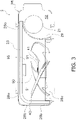
- the outdoor unit 2 includes a casing 28 having a substantially rectangular parallelepiped appearance, as shown in FIGS. 2 and 3 .
- a casing 28 having a substantially rectangular parallelepiped appearance, as shown in FIGS. 2 and 3 .
- an internal space of the casing 28 is divided by a partition plate 29 into a fan chamber S1 and a machine chamber S2.
- the machine chamber S2 in addition to the compressor 21 shown in FIG. 3 , although illustration is omitted in FIG. 3 , for example, the four-way valve 22, the expansion valve 24, and the accumulator 25 are disposed.
- the outdoor heat exchanger 23 and the outdoor fan 40 are disposed in the fan chamber S1.
- the outdoor heat exchanger 23 is L-shaped in a plan view. However, the shape of the outdoor heat exchanger 23 used in the outdoor unit 2 is not limited to L-shaped.
- openings 28a and 28b connected to the fan chamber S1 are formed on the opposite side of the outdoor fan 40 across the outdoor heat exchanger 23.
- the outdoor air flows into the fan chamber S1 from the openings 28a and 28b through the outdoor heat exchanger 23.
- a bell mouth 28c is disposed on the opposite side of the outdoor heat exchanger 23 across the outdoor fan 40.
- the bell mouth 28c includes a circular opening 28d when viewed in a rotating shaft direction of the outdoor fan 40.
- air is blown out from the inside of the fan chamber S1 to the outside through the bell mouth 28c.
- the circular opening 28d of the bell mouth 28c is covered by a grill 28e.
- the openings 28a and 28b of the casing 28 and the opening 28d of the bell mouth 28c are open even when the outdoor fan 40 is not driven. Therefore, if a strong wind blows outdoors, the strong wind blowing into the fan chamber S1 through the openings 28a and 28b or the opening 28d of the bell mouth 28c blows against the outdoor fan 40. The strong wind causes the outdoor fan 40 to rotate at a high speed, thereby generating a stress in the outdoor fan 40.
- the outdoor fan 40 is driven by a fan motor 90.
- the fan motor 90 is supported by a fan motor base 95.
- the fan motor base 95 fixes the fan motor 90 to the casing 28 with the outdoor unit 2 installed such that a rotating shaft 91 of the fan motor 90 extends substantially horizontally.
- the outdoor fan 40 may have the rotating shaft.
- the outdoor fan 40 When the outdoor fan 40 is attached to the horizontally extending rotating shaft 91, the outdoor fan 40 generates an air flow that flows substantially horizontally.
- the outdoor fan 40 is an axial fan.
- the outdoor fan 40 includes a hub 80 and a plurality of blades 42 extending radially from the hub 80.
- FIG. 4 is a view showing the outdoor fan 40 viewed from the rear side (side of the outdoor heat exchanger 23).
- the surface of the blade 42 drawn in FIG. 4 is a negative pressure surface 49.
- the negative pressure surface 49 is a surface on the side on which air flows in (upstream in the air flow direction) when the outdoor fan 40 is rotated.
- a pressure surface 48 is a surface on the side on which air flows out (downstream in the air flow direction) when the outdoor fan 40 is rotated.
- Each blade 42 includes a leading edge 43 located forward and a trailing edge 44 located rearward of the rotation direction (direction of arrows AR1 and AR2).
- the trailing edge 44 includes a depression 50 depressed in the rotation direction.
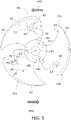
- FIG. 5 is a view showing the outdoor fan 40 viewed from the front side (side of the grill 28e).
- the surface of the blade 42 drawn in FIG. 5 is the pressure surface 48.
- the rotation direction of the outdoor fan 40 shown in FIG. 5 is in the direction of arrows AR3 and AR4.
- Each blade 42 includes a reinforcing protrusion 60 located at least forwardmost of the rotation direction of the depression 50 and having a wall thickness thicker than a surrounding portion.
- Each blade 42 includes the reinforcing protrusion 60 on the pressure surface 48.
- the reinforcing protrusion 60 protrudes from the pressure surface 48 of each blade 42 and does not protrude from the negative pressure surface 49.
- a rear end re of the reinforcing protrusion 60 (see FIG. 5 ) has a portion that substantially agrees with the depression 50 when viewed in the rotating shaft direction.
- the reinforcing protrusion 60 of the embodiment When viewed in the rotating shaft direction, the reinforcing protrusion 60 of the embodiment has substantially a shape obtained by removing a small fan shape having the same center point as a large fan shape (shape that partially overlaps the shape of the depression 50) from the large fan shape (hereafter, this shape is called a fan surface shape).
- the reinforcing protrusion 60 preferably has the fan surface shape substantially.
- the shape of the reinforcing protrusion 60 is not limited to the fan surface shape.
- FIG. 6 is an enlarged view of a cut surface shape of the reinforcing protrusion 60 cut along the line I-I of FIG. 5 and a surrounding portion 61 thereof.
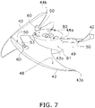
- FIG. 7 is a perspective view of the outdoor fan 40.
- a wall thickness th1 of the reinforcing protrusion 60 is thicker than a wall thickness th2 of the blade 42 in the surrounding portion 61 of the reinforcing protrusion 60.
- the wall thickness th2 of the surrounding portion 61 is the distance from the pressure surface 48 to the negative pressure surface 49 in the thinnest portion of the surrounding portion 61.
- the wall thickness th1 of the reinforcing protrusion 60 is the distance from a flat surface 60a of the reinforcing protrusion 60 to the negative pressure surface 49.
- the place of the flat surface 60a is the portion having the thickest wall thickness in the reinforcing protrusion 60.
- the reinforcing protrusion 60 extends radially inside of the first virtual line Li1 and extends radially outside of the second virtual line Li2.
- the first virtual line Li1 and the second virtual line Li2 respectively pass through a rearmost first endpoint P1 of the rotation direction on the radially inside of the rear end re that substantially overlaps the depression 50, and a rearmost second endpoint P2 on the radially outside of the rear end re.
- the reinforcing protrusion 60 includes the rear end re that substantially agrees with the depression 50 when viewed in the rotating shaft direction.
- the U-shaped portion on the rear side of the rotation direction of the reinforcing protrusion 60 is the rear end re.
- the rear end re of the reinforcing protrusion 60 includes the rearmost first endpoint P1 of the rotation direction on the radially inside.
- the rear end re of the reinforcing protrusion 60 includes the rearmost second endpoint P2 on the radially outside of the rear end re.
- the first virtual line Li1 passing through the first endpoint P1 and perpendicular to the radial direction can be drawn.
- the second virtual line Li2 passing through the second endpoint P2 and perpendicular to the radial direction can be drawn.
- the reinforcing protrusion 60 extends radially inside of the first virtual line Li1 and extends radially outside of the second virtual line Li2. Note that the reinforcing protrusion 60 has a configuration in which the rear end re does not overlap the whole of the depression 50, but the rear end re overlaps only some portion of the depression 50.
- the reinforcing protrusion 60 has a height h1 from the pressure surface 48 to the flat surface 60a.
- the reinforcing protrusion 60 inclines gently from the flat surface 60a to the pressure surface 48. Therefore, it is assumed that a contour when the reinforcing protrusion 60 is sliced thinly at half of the height h1 is a boundary line BL of the reinforcing protrusion 60.
- the boundary line BL of the reinforcing protrusion 60 the first endpoint P1 and the second endpoint P2 are defined.
- the outdoor fan 40 aims to improve blast performance and suppress noise by providing the depression 50 in the trailing edge 44 of each blade 42. Extending the reinforcing protrusion 60 disposed forwardmost of the rotation direction of the depression 50 in directions toward and away from the rotating shaft 91 can reinforce the surrounding portion of the depression 50. As a result, the outdoor fan 40, which is an axial fan, is able to thin the plurality of blades 42 and improve the blast performance.
- the outdoor fan 40 is a propeller fan.
- the outdoor fan 40 includes the hub 80 attached to the rotating shaft 91 of the fan motor 90.
- the hub 80 includes a cylindrical outer wall 81.
- the cylindrical outer wall 81 has a substantially constant thickness.
- the plurality of blades 42 is fixed to the outer wall 81 of the hub 80. In other words, the plurality of blades 42 is formed to protrude from an outer peripheral edge of the hub 80.
- the hub 80 and the plurality of blades 42 are made of resin.
- the hub 80 and the plurality of blades 42 are integrally molded.
- the hub 80 and the plurality of blades 42 are integrally molded, for example, by injection molding.
- This embodiment describes a case where the number of blades 42 fixed to the hub 80 is three, but the number of blades 42 is not limited to three.
- the number of blades 42 may be two, or four or more.
- a diameter of a circle passing through an outer peripheral portion 40a of the outdoor fan 40 is, for example, 500 mm to 700 mm.
- the shapes of the plurality of blades 42 are the same as each other. Pitch angles Pt1, Pt2, and Pt3 of the plurality of blades 42 are different from each other.
- the outdoor fan 40 is a fan of unequal pitch.
- the pitch angles Pt1, Pt2, and Pt3 are, for example, 110 degrees, 120 degrees, and 130 degrees, respectively.
- the leading edge 43 draws a recessed curve with respect to the rotation direction.
- the leading edge 43 extends out in the rotation direction as approaching the outer peripheral portion 40a.
- an outer peripheral end 43b of the leading edge 43 is located forward, in the rotation direction, of a straight line passing through a connection portion 43a between the leading edge 43 and the hub 80 and the rotating shaft 91.
- the trailing edge 44 of each blade 42 draws a curve Cv1 shown by a long dashed double-short dashed line in FIG. 4 , excluding the portion of the depression 50.
- the curve Cv1 draws a smooth curve protruding in a direction opposite to the rotation direction.
- an outer peripheral end 44b of the trailing edge 44 is located forward, in the rotation direction, of a straight line passing through a connection portion 44a between the trailing edge 44 and the hub 80 and the rotating shaft 91.
- the portion recessed in the rotation direction from the curve Cv1 is the depression 50.
- the depression 50 is divided into a first edge 51, a second edge 52, and a corner 53.
- the corner 53 shows a bow shape when viewed in the rotating shaft direction.
- the first edge 51 extends from the corner 53 toward the rear of the rotation direction.
- the second edge 52 is located farther from the rotating shaft 91 than the first edge 51.
- the second edge 52 extends from the corner 53 toward the rear of the rotation direction.
- Each blade 42 is inclined with respect to a plane perpendicular to the rotating shaft 91.
- the trailing edge 44 of each blade 42 protrudes in the wind blow-out direction (direction from the blade 42 toward the grill 28e) from the leading edge 43.
- the leading edge 43 is disposed closer to the fan motor 90, and the trailing edge 44 is disposed farther from the fan motor 90.
- a recessed surface is formed on the pressure surface 48 of each blade 42, and a protruding surface is formed on the negative pressure surface 49.
- the wall thickness of the blade 42 increases in a connection portion with the hub 80, and decreases toward the outer peripheral portion 40a.
- the wall thickness th1 of the reinforcing protrusion 60 shown in FIG. 6 is preferably 1.5 times or less of the wall thickness th2 of each blade 42 in the thinnest portion of the surrounding portion 61 of the reinforcing protrusion 60.
- the wall thickness th2 of each blade 42 is, for example, 3 mm to 8 mm.
- the wall thickness th1 of the reinforcing protrusion 60 is, for example, a thickness satisfying the condition of 4.5 mm to 12 mm and 1.5 times or less of the wall thickness th2. It is preferable that the height h1 of the reinforcing protrusion 60 from the pressure surface 48 of the blade 42 is 3 mm or less.
- the height h1 from the pressure surface 48 of the blade 42 is preferably set to 1 mm or more and 3 mm or less. Setting the wall thickness th1 and/or height h1 of the reinforcing protrusion 60 as described above makes it possible to suppress the increase in noise while performing reinforcement.
- an inclined surface 60c between the flat surface 60a of the reinforcing protrusion 60 and the pressure surface 48 draws a gentle curve protruding outward.
- an inclined surface 49a that draws a gentle curve protruding toward the side of the pressure surface 48 is formed from an outer peripheral side end 60d of the reinforcing protrusion 60.
- the depression 50 formed in the trailing edge 44 of the blade 42 is disposed closer to the outer peripheral portion 40a than the connection portion between the blade 42 and the hub 80.
- a radius r3 of a circle Cr1 passing through a rotation direction front end 53a of the corner 53 is greater than an intermediate radius between a radius r1 of the hub 80 and a radius r2 of the outer peripheral portion 40a of the outdoor fan 40 (r3 > ((r1 + r2) ⁇ 2)).
- the depression 50 shows a wedge shape with the tip rounded to a bow shape when viewed in the rotating shaft direction.
- the depression 50 is divided into the bow-shape corner 53 located forwardmost of the rotation direction, the first edge 51 located radially inside the corner 53, and the second edge 52 located radially outside the corner 53.
- the reinforcing protrusion 60 extends from at least the corner 53 to approach the rotating shaft 91. At the same time, the reinforcing protrusion 60 extends at least from the corner 53 to move away from the rotating shaft 91.
- the corner 53 is arc-shaped.
- the arc shape is one type of bow shape.
- FIG. 8 is an enlarged view of the depression 50 and the surroundings thereof.
- This boundary line BL is a line indicating the contour when the reinforcing protrusion 60 is sliced at half of the height h1.
- the rear end re is set such that an angle k formed by a first line segment Ls1 connecting the inner peripheral end P5 close to the rotating shaft 91 and a center point PO of the arc shape, and a second line segment Ls2 connecting the outer peripheral end P6 far from the rotating shaft 91 and the center point PO is 180 degrees or less.
- the angle k formed is an angle on the side of the rear end re.
- the angle k formed is preferably set, for example, to 60 degrees or more and 150 degrees or less.
- a length Lg1 of a forward portion of the reinforcing protrusion 60 is longer than a length Lg2 of a rearward portion of the reinforcing protrusion 60.
- the forward portion is positioned forward of a front end 50a of the depression 50 in the rotation direction.
- the rearward portion is positioned rearward of the front end 50a of the depression 50 in the rotation direction.
- the front end 50a is in front of the depression 50 in the rotation direction.
- the length Lg1 of the forward portion of the reinforcing protrusion 60 which is forward of the front end 50a in the rotation direction is preferably set to, for example, 10 mm or more and 50 mm or less.
- the rear end re of the reinforcing protrusion 60 does not span the first edge 51 and the second edge 52.
- the rear end re may be configured to span the first edge 51 and the second edge 52.
- the too long rear end re will increase noise, and therefore the rear end re extends halfway of the first edge 51 and the second edge 52.
- the rear end re is preferably formed so as not to exceed the midpoint of the first edge 51 and the second edge 52. Note that in FIG. 9 , the cross-sectional shape when cut along the line II-II is as shown in FIG. 6 , as in the embodiment.
- the reinforcing protrusion 60 is molded integrally with the blade 42 with the same resin as the blade 42.
- the reinforcing protrusion 60 a member made of a material different from the blade 42 may be attached.
- the reinforcing protrusion 60 may be formed by adhering a thin plate of resin, metal, or ceramic to the blade 42.
- the above-described outdoor fan 40 which is an axial fan, includes the depression 50 depressed toward the rotation direction in the trailing edge 44 of each blade 42. With the depression 50, the outdoor fan 40 aims to improve the blast performance and suppress noise. By extending the reinforcing protrusion 60 disposed forwardmost of the rotation direction of the depression 50 in the directions toward and away from the rotating shaft 91, the outdoor fan 40 can reinforce the surroundings of the depression 50 of the blade 42.
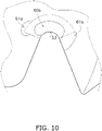
- the outdoor fan 40 can disperse the stress concentrated on the corner 53 over a wide range, such as a surrounding portion 61a on the inner peripheral side of the fan surface shape reinforcing protrusion 60, a center portion 60b of the reinforcing protrusion 60, and a surrounding portion 61b on the outer peripheral side of the reinforcing protrusion 60, as shown in FIG. 10 .
- the outdoor fan 40 can easily thin the blade 42 and improve the blast performance.
- the above-described outdoor fan 40 keeps the wall thickness th1 of the thickest portion of the reinforcing protrusion 60 to 1.5 times or less of the wall thickness th2 of the thinnest portion around the reinforcing protrusion 60, thereby suppressing the increase in noise caused by the reinforcing protrusion 60. Conversely, when the value of (th1 ⁇ th2) is 1.6 or more, a remarkable increase in noise may be observed.
- the above-described outdoor fan 40 can suppress the increase in noise caused by the reinforcing protrusion 60 by suppressing the height h1 of the reinforcing protrusion 60 to 3 mm or less. For example, if the height h1 of the reinforcing protrusion 60 is set to 4 mm or more, a remarkable increase in noise may be observed.
- the above-described outdoor fan 40 makes it easy to both suppress the increase in noise and reinforce the surroundings of the corner 53.
- the forward portion of the reinforcing protrusion 60 is positioned forward of the front end 50a of the depression 50 and the rear portion of the reinforcing protrusion 60 is positioned rearward of the front end 50a of the depression 50.
- the corner 53 of the above-described outdoor fan 40 has a bow shape when viewed in the rotating shaft direction.
- the reinforcing protrusion 60 does not include the portion located rearward of the rearmost third endpoint P3 in the rotation direction on the radially inside of the corner 53, and the portion located rearward of the rearmost fourth endpoint P4 on the radially outside of the corner 53.
- the reinforcing protrusion 60 shown in FIG. 8 has a smaller blast sound than the reinforcing protrusion 60 shown in FIG.
- the bow shape here means a bent shape like a bow.
- the bow shape includes, for example, an arc, an elliptical arc, a shape obtained by cutting a part from an egg shape, and a shape obtained by cutting a part from an ellipse.
- the reinforcing protrusion 60 of the above-described outdoor fan 40 does not protrude from the negative pressure surface 59. In this way, by not providing the reinforcing protrusion 60 on the negative pressure surface 59, the outdoor fan 40 can suppress the increase in noise more than when providing on both the pressure surface 58 and the negative pressure surface 59.
- the above-described outdoor fan 40 is provided in a refrigeration cycle apparatus.
- the refrigeration cycle apparatus is an apparatus that executes a refrigeration cycle.
- the refrigeration cycle apparatus can be applied to, for example, a heat pump water heater, a refrigerator, and a cooling apparatus for cooling the inside of a refrigerator, in addition to the air conditioner 1.
- the air conditioner 1 includes the outdoor heat exchanger 23, which is a heat exchanger provided in the refrigerant circuit 10 that executes the refrigeration cycle to exchange heat between the refrigerant circulating in the refrigerant circuit 10 and air.
- the outdoor fan 40 is an axial fan that creates an air flow for the outdoor heat exchanger 23.
- Patent Literature 1 JP 2005-140081 A
Landscapes
- Engineering & Computer Science (AREA)
- Mechanical Engineering (AREA)
- General Engineering & Computer Science (AREA)
- Chemical & Material Sciences (AREA)
- Combustion & Propulsion (AREA)
- Structures Of Non-Positive Displacement Pumps (AREA)
- Other Air-Conditioning Systems (AREA)
Abstract
Description
- The present invention relates to an axial fan having a depression depressed in a rotation direction on a trailing edge of each blade, and a refrigeration cycle apparatus including the axial fan.
- Conventionally, as described in Patent Literature 1 (
JP 2005-140081 A - In the axial fan, centrifugal force generated by rotation of the blade causes force to be applied to the blade in a direction outward from a rotating shaft. When the blade including the depression as described above rotates, a stress is concentrated around the depression. Therefore, in the axial fan including the depression, if the thickness of the blade is reduced in order to improve blast performance, damage is likely to occur around the depression.
- The axial fan including the depression in the blade has a problem of inhibiting damage to the blade having high blast performance.
- An axial fan according to a first aspect is an axial fan rotating around a rotating shaft, and includes a hub and a plurality of blades extending in a radial direction from the hub. Each of the blades includes a leading edge located forward of a rotation direction and a trailing edge located rearward. The trailing edge includes a depression depressed forward of the rotation direction. Each of the blades includes a reinforcing protrusion located at least forwardmost of the rotation direction of the depression and having a wall thickness thicker than a surrounding portion. As viewed in a rotating shaft direction, when a first virtual line and a second virtual line perpendicular to the radial direction are drawn, the reinforcing protrusion extends radially inside of the first virtual line and extends radially outside of the second virtual line, the first virtual line and the second virtual line respectively passing through a rearmost first endpoint of the rotation direction on a radially inside of a rear end that substantially overlaps the depression, and a rearmost second endpoint on a radially outside of the rear end.
- By extending at least the reinforcing protrusion located forwardmost of the rotation direction of the depression in directions toward and away from the rotating shaft, the axial fan according to the first aspect can reinforce surroundings of the depression of the blade. As a result, the axial fan can easily thin the blade and improve the blast performance.
- The axial fan according to a second aspect is the axial fan according to the first aspect, in which the wall thickness of a thickest portion of a place including the reinforcing protrusion of each of the blades is 1.5 times or less of the wall thickness of each of the blades in a thinnest portion around the reinforcing protrusion.
- By suppressing the wall thickness of the thickest portion of the reinforcing protrusion to 1.5 times or less of the wall thickness of the thinnest portion around the reinforcing protrusion, the axial fan according to the second aspect can suppress the increase in noise caused by the reinforcing protrusion.
- The axial fan according to a third aspect is the axial fan according to the first aspect or second aspect, in which a height of the reinforcing protrusion from a pressure surface of each of the blades is 3 mm or less.
- By suppressing the height of the reinforcing protrusion to 3 mm or less, the axial fan according to the third aspect can suppress the increase in noise caused by the reinforcing protrusion.
- The axial fan according to a fourth aspect is the axial fan according to any one of the first aspect to the third aspect, in which in the reinforcing protrusion, in regard to a length in a direction perpendicular to the radial direction, a length of a forward portion of the reinforcing protrusion is longer than a length of a rearward portion of the reinforcing protrusion. The forward portion being positioned forward of a front end of the depression in the rotation direction. The rearward portion being positioned rearward of the front end of the depression in the rotation direction. The front end is in front of the depression in the rotation direction.
- By making the length of the forward portion forward of the front end of the depression longer than the length of the rearward portion, the axial fan according to the fourth aspect makes it easier to both suppress the increase in noise and reinforce the surroundings of the depression at the same time.
- The axial fan according to a fifth aspect is the axial fan according to the fourth aspect, in which the length of the forward portion forward of the front end of the depression in the rotation direction is 10 mm or more and 50 mm or less.
- The axial fan according to a sixth aspect is the axial fan according to any one of the first aspect to the fifth aspect, in which the depression is divided into a bow-shaped corner located forwardmost of the rotation direction, a first edge located radially inside the corner, and a second edge located radially outside the corner. The reinforcing protrusion does not include a portion located rearward of a rearmost third endpoint in the rotation direction radially inside the corner, and a portion located rearward of a rearmost fourth endpoint radially outside the corner.
- By the reinforcing protrusion not including the portion located rearward of the third endpoint and the portion located rearward of the fourth endpoint, the axial fan according to the sixth aspect can suppress the increase in noise caused by the reinforcing protrusion.
- The axial fan according to a seventh aspect is the axial fan according to any one of the first aspect to the sixth aspect, in which the reinforcing protrusion protrudes from the pressure surface of each of the blades and does not protrude from a negative pressure surface.
- By not providing the reinforcing protrusion on the negative pressure surface, the axial fan according to the seventh aspect can suppress the increase in noise.
- The axial fan according to an eighth aspect is the axial fan according to any one of the first aspect to the seventh aspect, in which the rear end of the reinforcing protrusion has an arc shape, and when a first line segment connecting an inner peripheral end near the rotating shaft and a center point of the arc shape of the rear end is drawn, and when a second line segment connecting an outer peripheral end far from the rotating shaft and the center point is drawn, an angle formed by the first line segment and the second line segment on a side of the rear end is 60 degrees or more and 150 degrees or less.
- A refrigeration cycle apparatus according to a ninth aspect includes a refrigerant circuit including a heat exchanger and executing a refrigeration cycle, and the axial fan according to any one of the first aspect to the eighth aspect.
- By extending at least the reinforcing protrusion located forwardmost of the rotation direction of the depression in directions toward and away from the rotating shaft, the refrigeration cycle apparatus according to the ninth aspect can reinforce surroundings of the depression. As a result, the axial fan can easily thin the blade and improve the blast performance.
-
-
FIG. 1 is a circuit diagram showing a refrigerant circuit of an air conditioner according to an embodiment. -
FIG. 2 is a front view showing an appearance of an outdoor unit of the air conditioner. -
FIG. 3 is a schematic cross-sectional view for describing an internal structure of the outdoor unit ofFIG. 2 . -
FIG. 4 is a rear view showing one example of an outdoor fan used in the outdoor unit ofFIG. 2 . -
FIG. 5 is a front view of the outdoor fan ofFIG. 4 . -
FIG. 6 is an enlarged cross-sectional view of the outdoor fan when cut along the line I-I ofFIG. 5 . -
FIG. 7 is a perspective view of the outdoor fan ofFIG. 5 . -
FIG. 8 is a partially enlarged plan view of the outdoor fan for describing a reinforcing protrusion of the outdoor fan ofFIG. 5 . -
FIG. 9 is a partially enlarged plan view of the outdoor fan for describing the reinforcing protrusion according to a modification. -
FIG. 10 is a partially enlarged plan view of the outdoor fan for describing reinforcement by the reinforcing protrusion. -
FIG. 1 is a diagram showing anair conditioner 1 as an example of a refrigeration cycle apparatus. Theair conditioner 1 includes anoutdoor unit 2, which serves as a heat source, and anindoor unit 3, which uses heat obtained by theoutdoor unit 2. Theoutdoor unit 2 and theindoor unit 3 are connected to each other byrefrigerant connection pipes 4 and 5. Theoutdoor unit 2 includesshutoff valves refrigerant connection pipes 4 and 5. - A
refrigerant circuit 10 is formed in theoutdoor unit 2 and theindoor unit 3 connected by therefrigerant connection pipes 4 and 5. Therefrigerant circuit 10 includes acompressor 21, a four-way valve 22, anoutdoor heat exchanger 23, anexpansion valve 24, anaccumulator 25, and anindoor heat exchanger 31. The four-way valve 22 switches the direction in which a refrigerant flows, for example, between a cooling operation and a heating operation of theair conditioner 1. - During the cooling operation, the four-
way valve 22 is switched such that the refrigerant flows through the route shown by the solid line. During the cooling operation, the high-temperature, high-pressure refrigerant discharged from thecompressor 21 flows through theoutdoor heat exchanger 23. The outdoor heat exchanger 23 exchanges heat between the outdoor air and the refrigerant. The refrigerant from which heat is taken away in theoutdoor heat exchanger 23 is decompressed in theexpansion valve 24. The refrigerant decompressed in theexpansion valve 24 flows through theindoor heat exchanger 31. Theindoor heat exchanger 31 exchanges heat between the indoor air and the refrigerant. The refrigerant that has obtained heat from the indoor air in theindoor heat exchanger 31 is taken into thecompressor 21 through the four-way valve 22 and theaccumulator 25. When passing through theaccumulator 25, the refrigerant is separated into a gas refrigerant and a liquid refrigerant, and the gas refrigerant is mainly taken into thecompressor 21. In this way, a vapor compression refrigeration cycle is performed in therefrigerant circuit 10, and the room is cooled by the indoor air from which heat is taken away by heat exchange in theindoor heat exchanger 31. Theoutdoor heat exchanger 23 is supplied with outdoor air by anoutdoor fan 40. Theindoor heat exchanger 31 is supplied with indoor air by anindoor fan 32. Theindoor fan 32 is a cross-flow fan. - During the heating operation, the four-
way valve 22 is switched such that the refrigerant flows through the route shown by the broken line. During the heating operation, the high-temperature, high-pressure refrigerant discharged from thecompressor 21 flows through theindoor heat exchanger 31 through the four-way valve 22. Theindoor heat exchanger 31 exchanges heat between the indoor air and the refrigerant. The refrigerant that has dissipated heat in theindoor heat exchanger 31 is decompressed in theexpansion valve 24. The refrigerant decompressed in theexpansion valve 24 flows through theoutdoor heat exchanger 23. Theoutdoor heat exchanger 23 exchanges heat between the outdoor air and the refrigerant. The refrigerant that has obtained heat from the outdoor air in theoutdoor heat exchanger 23 is taken into thecompressor 21 through the four-way valve 22 and theaccumulator 25. In this way, the vapor compression refrigeration cycle is performed in therefrigerant circuit 10, and the room is heated by the indoor air that has obtained heat by heat exchange in theindoor heat exchanger 31. - The
outdoor unit 2 includes acasing 28 having a substantially rectangular parallelepiped appearance, as shown inFIGS. 2 and3 . In theoutdoor unit 2, an internal space of thecasing 28 is divided by apartition plate 29 into a fan chamber S1 and a machine chamber S2. In the machine chamber S2, in addition to thecompressor 21 shown inFIG. 3 , although illustration is omitted inFIG. 3 , for example, the four-way valve 22, theexpansion valve 24, and theaccumulator 25 are disposed. In the fan chamber S1, theoutdoor heat exchanger 23 and theoutdoor fan 40 are disposed. Theoutdoor heat exchanger 23 is L-shaped in a plan view. However, the shape of theoutdoor heat exchanger 23 used in theoutdoor unit 2 is not limited to L-shaped. - In the
casing 28,openings outdoor fan 40 across theoutdoor heat exchanger 23. When theoutdoor fan 40 is driven, the outdoor air flows into the fan chamber S1 from theopenings outdoor heat exchanger 23. In thecasing 28, abell mouth 28c is disposed on the opposite side of theoutdoor heat exchanger 23 across theoutdoor fan 40. Thebell mouth 28c includes acircular opening 28d when viewed in a rotating shaft direction of theoutdoor fan 40. When theoutdoor fan 40 is driven, air is blown out from the inside of the fan chamber S1 to the outside through thebell mouth 28c. Thecircular opening 28d of thebell mouth 28c is covered by agrill 28e. When theoutdoor fan 40 is driven, the outdoor air taken into thecasing 28 from theopenings casing 28 is blown out of thecasing 28 through theoutdoor heat exchanger 23, theoutdoor fan 40, thecircular opening 28d of thebell mouth 28c, and thegrill 28e. In this way, heat is exchanged between the outdoor air passing through theoutdoor heat exchanger 23 and the refrigerant flowing through theoutdoor heat exchanger 23. - The
openings casing 28 and theopening 28d of thebell mouth 28c are open even when theoutdoor fan 40 is not driven. Therefore, if a strong wind blows outdoors, the strong wind blowing into the fan chamber S1 through theopenings opening 28d of thebell mouth 28c blows against theoutdoor fan 40. The strong wind causes theoutdoor fan 40 to rotate at a high speed, thereby generating a stress in theoutdoor fan 40. - The
outdoor fan 40 is driven by afan motor 90. Thefan motor 90 is supported by afan motor base 95. Thefan motor base 95 fixes thefan motor 90 to thecasing 28 with theoutdoor unit 2 installed such that arotating shaft 91 of thefan motor 90 extends substantially horizontally. Here, the case where thefan motor 90 has therotating shaft 91 is shown, but theoutdoor fan 40 may have the rotating shaft. When theoutdoor fan 40 is attached to the horizontally extendingrotating shaft 91, theoutdoor fan 40 generates an air flow that flows substantially horizontally. - The
outdoor fan 40 is an axial fan. Theoutdoor fan 40 includes ahub 80 and a plurality ofblades 42 extending radially from thehub 80.FIG. 4 is a view showing theoutdoor fan 40 viewed from the rear side (side of the outdoor heat exchanger 23). The surface of theblade 42 drawn inFIG. 4 is anegative pressure surface 49. In other words, thenegative pressure surface 49 is a surface on the side on which air flows in (upstream in the air flow direction) when theoutdoor fan 40 is rotated. Apressure surface 48 is a surface on the side on which air flows out (downstream in the air flow direction) when theoutdoor fan 40 is rotated. - Each
blade 42 includes aleading edge 43 located forward and a trailingedge 44 located rearward of the rotation direction (direction of arrows AR1 and AR2). The trailingedge 44 includes adepression 50 depressed in the rotation direction. -
FIG. 5 is a view showing theoutdoor fan 40 viewed from the front side (side of thegrill 28e). The surface of theblade 42 drawn inFIG. 5 is thepressure surface 48. The rotation direction of theoutdoor fan 40 shown inFIG. 5 is in the direction of arrows AR3 and AR4. - Each
blade 42 includes a reinforcingprotrusion 60 located at least forwardmost of the rotation direction of thedepression 50 and having a wall thickness thicker than a surrounding portion. Eachblade 42 includes the reinforcingprotrusion 60 on thepressure surface 48. In other words, the reinforcingprotrusion 60 protrudes from thepressure surface 48 of eachblade 42 and does not protrude from thenegative pressure surface 49. A rear end re of the reinforcing protrusion 60 (seeFIG. 5 ) has a portion that substantially agrees with thedepression 50 when viewed in the rotating shaft direction. When viewed in the rotating shaft direction, the reinforcingprotrusion 60 of the embodiment has substantially a shape obtained by removing a small fan shape having the same center point as a large fan shape (shape that partially overlaps the shape of the depression 50) from the large fan shape (hereafter, this shape is called a fan surface shape). The reinforcingprotrusion 60 preferably has the fan surface shape substantially. However, the shape of the reinforcingprotrusion 60 is not limited to the fan surface shape.FIG. 6 is an enlarged view of a cut surface shape of the reinforcingprotrusion 60 cut along the line I-I ofFIG. 5 and a surroundingportion 61 thereof.FIG. 7 is a perspective view of theoutdoor fan 40. - A wall thickness th1 of the reinforcing
protrusion 60 is thicker than a wall thickness th2 of theblade 42 in the surroundingportion 61 of the reinforcingprotrusion 60. The wall thickness th2 of the surroundingportion 61 is the distance from thepressure surface 48 to thenegative pressure surface 49 in the thinnest portion of the surroundingportion 61. The wall thickness th1 of the reinforcingprotrusion 60 is the distance from aflat surface 60a of the reinforcingprotrusion 60 to thenegative pressure surface 49. The place of theflat surface 60a is the portion having the thickest wall thickness in the reinforcingprotrusion 60. - As shown in
FIG. 5 , as viewed in the rotating shaft direction, when a first virtual line Li1 and a second virtual line Li2 perpendicular to the radial direction are drawn, the reinforcingprotrusion 60 extends radially inside of the first virtual line Li1 and extends radially outside of the second virtual line Li2. The first virtual line Li1 and the second virtual line Li2 respectively pass through a rearmost first endpoint P1 of the rotation direction on the radially inside of the rear end re that substantially overlaps thedepression 50, and a rearmost second endpoint P2 on the radially outside of the rear end re. - Here, the above-described first endpoint P1, the second endpoint P2, the first virtual line Li1, and the second virtual line Li2 will be described with reference to
FIG. 5 . The reinforcingprotrusion 60 includes the rear end re that substantially agrees with thedepression 50 when viewed in the rotating shaft direction. InFIG. 5 , the U-shaped portion on the rear side of the rotation direction of the reinforcingprotrusion 60 is the rear end re. The rear end re of the reinforcingprotrusion 60 includes the rearmost first endpoint P1 of the rotation direction on the radially inside. The rear end re of the reinforcingprotrusion 60 includes the rearmost second endpoint P2 on the radially outside of the rear end re. The first virtual line Li1 passing through the first endpoint P1 and perpendicular to the radial direction can be drawn. The second virtual line Li2 passing through the second endpoint P2 and perpendicular to the radial direction can be drawn. As shown inFIG. 5 , the reinforcingprotrusion 60 extends radially inside of the first virtual line Li1 and extends radially outside of the second virtual line Li2. Note that the reinforcingprotrusion 60 has a configuration in which the rear end re does not overlap the whole of thedepression 50, but the rear end re overlaps only some portion of thedepression 50. - Here, the above description will be described in a little more detail. As shown in
FIG. 6 , the reinforcingprotrusion 60 has a height h1 from thepressure surface 48 to theflat surface 60a. The reinforcingprotrusion 60 inclines gently from theflat surface 60a to thepressure surface 48. Therefore, it is assumed that a contour when the reinforcingprotrusion 60 is sliced thinly at half of the height h1 is a boundary line BL of the reinforcingprotrusion 60. For the boundary line BL of the reinforcingprotrusion 60, the first endpoint P1 and the second endpoint P2 are defined. There is almost no difference in positions of the first endpoint P1 and the second endpoint P2, whether the boundary line BL is set in this way or not. However, if the first endpoint P1 and the second endpoint P2 need to be determined more accurately, the boundary line BL is used. - The
outdoor fan 40 aims to improve blast performance and suppress noise by providing thedepression 50 in the trailingedge 44 of eachblade 42. Extending the reinforcingprotrusion 60 disposed forwardmost of the rotation direction of thedepression 50 in directions toward and away from the rotatingshaft 91 can reinforce the surrounding portion of thedepression 50. As a result, theoutdoor fan 40, which is an axial fan, is able to thin the plurality ofblades 42 and improve the blast performance. - The
outdoor fan 40 is a propeller fan. Theoutdoor fan 40 includes thehub 80 attached to therotating shaft 91 of thefan motor 90. Thehub 80 includes a cylindricalouter wall 81. The cylindricalouter wall 81 has a substantially constant thickness. The plurality ofblades 42 is fixed to theouter wall 81 of thehub 80. In other words, the plurality ofblades 42 is formed to protrude from an outer peripheral edge of thehub 80. Thehub 80 and the plurality ofblades 42 are made of resin. Thehub 80 and the plurality ofblades 42 are integrally molded. Thehub 80 and the plurality ofblades 42 are integrally molded, for example, by injection molding. - This embodiment describes a case where the number of
blades 42 fixed to thehub 80 is three, but the number ofblades 42 is not limited to three. The number ofblades 42 may be two, or four or more. A diameter of a circle passing through an outerperipheral portion 40a of theoutdoor fan 40 is, for example, 500 mm to 700 mm. - The shapes of the plurality of
blades 42 are the same as each other. Pitch angles Pt1, Pt2, and Pt3 of the plurality ofblades 42 are different from each other. In other words, theoutdoor fan 40 is a fan of unequal pitch. The pitch angles Pt1, Pt2, and Pt3 are, for example, 110 degrees, 120 degrees, and 130 degrees, respectively. When viewed in the rotating shaft direction, the leadingedge 43 draws a recessed curve with respect to the rotation direction. When viewed in the rotating shaft direction, the leadingedge 43 extends out in the rotation direction as approaching the outerperipheral portion 40a. In other words, when viewed in the rotating shaft direction, an outerperipheral end 43b of the leadingedge 43 is located forward, in the rotation direction, of a straight line passing through aconnection portion 43a between theleading edge 43 and thehub 80 and therotating shaft 91. The trailingedge 44 of eachblade 42 draws a curve Cv1 shown by a long dashed double-short dashed line inFIG. 4 , excluding the portion of thedepression 50. The curve Cv1 draws a smooth curve protruding in a direction opposite to the rotation direction. When viewed in the rotating shaft direction, an outerperipheral end 44b of the trailingedge 44 is located forward, in the rotation direction, of a straight line passing through aconnection portion 44a between the trailingedge 44 and thehub 80 and therotating shaft 91. The portion recessed in the rotation direction from the curve Cv1 is thedepression 50. - The
depression 50 is divided into afirst edge 51, asecond edge 52, and acorner 53. Thecorner 53 shows a bow shape when viewed in the rotating shaft direction. Thefirst edge 51 extends from thecorner 53 toward the rear of the rotation direction. Thesecond edge 52 is located farther from the rotatingshaft 91 than thefirst edge 51. Thesecond edge 52 extends from thecorner 53 toward the rear of the rotation direction. - Each
blade 42 is inclined with respect to a plane perpendicular to therotating shaft 91. The trailingedge 44 of eachblade 42 protrudes in the wind blow-out direction (direction from theblade 42 toward thegrill 28e) from the leadingedge 43. In other words, the leadingedge 43 is disposed closer to thefan motor 90, and the trailingedge 44 is disposed farther from thefan motor 90. A recessed surface is formed on thepressure surface 48 of eachblade 42, and a protruding surface is formed on thenegative pressure surface 49. The wall thickness of theblade 42 increases in a connection portion with thehub 80, and decreases toward the outerperipheral portion 40a. - The wall thickness th1 of the reinforcing
protrusion 60 shown inFIG. 6 is preferably 1.5 times or less of the wall thickness th2 of eachblade 42 in the thinnest portion of the surroundingportion 61 of the reinforcingprotrusion 60. The wall thickness th2 of eachblade 42 is, for example, 3 mm to 8 mm. The wall thickness th1 of the reinforcingprotrusion 60 is, for example, a thickness satisfying the condition of 4.5 mm to 12 mm and 1.5 times or less of the wall thickness th2. It is preferable that the height h1 of the reinforcingprotrusion 60 from thepressure surface 48 of theblade 42 is 3 mm or less. If the height h1 is too small, the strength of the reinforcingprotrusion 60 will be weakened. Therefore, for example, the height h1 from thepressure surface 48 of theblade 42 is preferably set to 1 mm or more and 3 mm or less. Setting the wall thickness th1 and/or height h1 of the reinforcingprotrusion 60 as described above makes it possible to suppress the increase in noise while performing reinforcement. - In the cross-sectional shape along the rotation direction shown in
FIG. 6 , aninclined surface 60c between theflat surface 60a of the reinforcingprotrusion 60 and thepressure surface 48 draws a gentle curve protruding outward. In addition, in the cross-sectional shape along the rotation direction shown inFIG. 6 , aninclined surface 49a that draws a gentle curve protruding toward the side of thepressure surface 48 is formed from an outerperipheral side end 60d of the reinforcingprotrusion 60. - The
depression 50 formed in the trailingedge 44 of theblade 42 is disposed closer to the outerperipheral portion 40a than the connection portion between theblade 42 and thehub 80. In other words, a radius r3 of a circle Cr1 passing through a rotation direction front end 53a of thecorner 53 is greater than an intermediate radius between a radius r1 of thehub 80 and a radius r2 of the outerperipheral portion 40a of the outdoor fan 40 (r3 > ((r1 + r2) ÷ 2)). - The
depression 50 shows a wedge shape with the tip rounded to a bow shape when viewed in the rotating shaft direction. Thedepression 50 is divided into the bow-shape corner 53 located forwardmost of the rotation direction, thefirst edge 51 located radially inside thecorner 53, and thesecond edge 52 located radially outside thecorner 53. The reinforcingprotrusion 60 extends from at least thecorner 53 to approach the rotatingshaft 91. At the same time, the reinforcingprotrusion 60 extends at least from thecorner 53 to move away from the rotatingshaft 91. In this embodiment, thecorner 53 is arc-shaped. The arc shape is one type of bow shape.FIG. 8 is an enlarged view of thedepression 50 and the surroundings thereof. Of thecorner 53, the rearmost point of the rotation direction on the radially inside is a third endpoint P3. Of thecorner 53, the rearmost point on the radially outside is a fourth endpoint P4. Of the portion where the rear end re and thedepression 50 overlap each other, rearmost points in the travel direction are an inner peripheral end P5 and an outer peripheral end P6. This boundary line BL is a line indicating the contour when the reinforcingprotrusion 60 is sliced at half of the height h1. The rear end re is set such that an angle k formed by a first line segment Ls1 connecting the inner peripheral end P5 close to therotating shaft 91 and a center point PO of the arc shape, and a second line segment Ls2 connecting the outer peripheral end P6 far from the rotatingshaft 91 and the center point PO is 180 degrees or less. Note that the angle k formed is an angle on the side of the rear end re. The angle k formed is preferably set, for example, to 60 degrees or more and 150 degrees or less. - For the length perpendicular to the radial direction, a length Lg1 of a forward portion of the reinforcing
protrusion 60 is longer than a length Lg2 of a rearward portion of the reinforcingprotrusion 60. The forward portion is positioned forward of afront end 50a of thedepression 50 in the rotation direction. The rearward portion is positioned rearward of thefront end 50a of thedepression 50 in the rotation direction. Thefront end 50a is in front of thedepression 50 in the rotation direction. - The length Lg1 of the forward portion of the reinforcing
protrusion 60 which is forward of thefront end 50a in the rotation direction is preferably set to, for example, 10 mm or more and 50 mm or less. - The above-described embodiment has described the case where the rear end re of the reinforcing
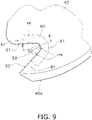
protrusion 60 does not span thefirst edge 51 and thesecond edge 52. However, as shown inFIG. 9 , the rear end re may be configured to span thefirst edge 51 and thesecond edge 52. However, the too long rear end re will increase noise, and therefore the rear end re extends halfway of thefirst edge 51 and thesecond edge 52. The rear end re is preferably formed so as not to exceed the midpoint of thefirst edge 51 and thesecond edge 52. Note that inFIG. 9 , the cross-sectional shape when cut along the line II-II is as shown inFIG. 6 , as in the embodiment. - The above-described embodiment has described the case where the reinforcing
protrusion 60 is molded integrally with theblade 42 with the same resin as theblade 42. However, as the reinforcingprotrusion 60, a member made of a material different from theblade 42 may be attached. For example, the reinforcingprotrusion 60 may be formed by adhering a thin plate of resin, metal, or ceramic to theblade 42. - The above-described
outdoor fan 40, which is an axial fan, includes thedepression 50 depressed toward the rotation direction in the trailingedge 44 of eachblade 42. With thedepression 50, theoutdoor fan 40 aims to improve the blast performance and suppress noise. By extending the reinforcingprotrusion 60 disposed forwardmost of the rotation direction of thedepression 50 in the directions toward and away from the rotatingshaft 91, theoutdoor fan 40 can reinforce the surroundings of thedepression 50 of theblade 42. Specifically, theoutdoor fan 40 can disperse the stress concentrated on thecorner 53 over a wide range, such as a surroundingportion 61a on the inner peripheral side of the fan surfaceshape reinforcing protrusion 60, acenter portion 60b of the reinforcingprotrusion 60, and a surroundingportion 61b on the outer peripheral side of the reinforcingprotrusion 60, as shown inFIG. 10 . As a result, theoutdoor fan 40 can easily thin theblade 42 and improve the blast performance. - The above-described
outdoor fan 40 keeps the wall thickness th1 of the thickest portion of the reinforcingprotrusion 60 to 1.5 times or less of the wall thickness th2 of the thinnest portion around the reinforcingprotrusion 60, thereby suppressing the increase in noise caused by the reinforcingprotrusion 60. Conversely, when the value of (th1 ÷ th2) is 1.6 or more, a remarkable increase in noise may be observed. - The above-described
outdoor fan 40 can suppress the increase in noise caused by the reinforcingprotrusion 60 by suppressing the height h1 of the reinforcingprotrusion 60 to 3 mm or less. For example, if the height h1 of the reinforcingprotrusion 60 is set to 4 mm or more, a remarkable increase in noise may be observed. - As shown in
FIG. 8 , by making the length Lg1 of the forward portion of the reinforcingprotrusion 60 longer than the length Lg2 of the rear portion, the above-describedoutdoor fan 40 makes it easy to both suppress the increase in noise and reinforce the surroundings of thecorner 53. In the rotation direction, the forward portion of the reinforcingprotrusion 60 is positioned forward of thefront end 50a of thedepression 50 and the rear portion of the reinforcingprotrusion 60 is positioned rearward of thefront end 50a of thedepression 50. - The
corner 53 of the above-describedoutdoor fan 40 has a bow shape when viewed in the rotating shaft direction. The reinforcingprotrusion 60 does not include the portion located rearward of the rearmost third endpoint P3 in the rotation direction on the radially inside of thecorner 53, and the portion located rearward of the rearmost fourth endpoint P4 on the radially outside of thecorner 53. As a result, it is possible to eliminate the portion extending along thefirst edge 51 and thesecond edge 52, and to suppress the increase in noise caused by the reinforcingprotrusion 60. Specifically, the reinforcingprotrusion 60 shown inFIG. 8 has a smaller blast sound than the reinforcingprotrusion 60 shown inFIG. 9 , with a difference only in the shape viewed in the rotating shaft direction. Note that the bow shape here means a bent shape like a bow. The bow shape includes, for example, an arc, an elliptical arc, a shape obtained by cutting a part from an egg shape, and a shape obtained by cutting a part from an ellipse. - The reinforcing
protrusion 60 of the above-describedoutdoor fan 40 does not protrude from the negative pressure surface 59. In this way, by not providing the reinforcingprotrusion 60 on the negative pressure surface 59, theoutdoor fan 40 can suppress the increase in noise more than when providing on both the pressure surface 58 and the negative pressure surface 59. - The above-described
outdoor fan 40 is provided in a refrigeration cycle apparatus. The refrigeration cycle apparatus is an apparatus that executes a refrigeration cycle. The refrigeration cycle apparatus can be applied to, for example, a heat pump water heater, a refrigerator, and a cooling apparatus for cooling the inside of a refrigerator, in addition to theair conditioner 1. Theair conditioner 1 includes theoutdoor heat exchanger 23, which is a heat exchanger provided in therefrigerant circuit 10 that executes the refrigeration cycle to exchange heat between the refrigerant circulating in therefrigerant circuit 10 and air. Theoutdoor fan 40 is an axial fan that creates an air flow for theoutdoor heat exchanger 23. - The embodiment of the present disclosure has been described above. It will be understood that various modifications to modes and details can be made without departing from the spirit and scope of the present disclosure recited in the claims.
-
- 1: air conditioner (example of refrigeration cycle apparatus)
- 10: refrigerant circuit
- 23: outdoor heat exchanger (example of heat exchanger)
- 40: outdoor fan (example of axial fan)
- 42: blade
- 43: leading edge
- 44: trailing edge
- 50: depression
- 51: first edge
- 52: second edge
- 53: corner
- 60: reinforcing protrusion
- Patent Literature 1:
JP 2005-140081 A
Claims (9)
- An axial fan (40) rotating around a rotating shaft, the axial fan (40) comprising:a hub (80); anda plurality of blades (42) extending in a radial direction from the hub,wherein each of the blades includes a leading edge (43) located forward of a rotation direction and a trailing edge (44) located rearward,the trailing edge includes a depression (50) depressed forward of the rotation direction,each of the blades includes a reinforcing protrusion (60) located at least forwardmost of the rotation direction of the depression and having a wall thickness thicker than a surrounding portion, andas viewed in a rotating shaft direction, when a first virtual line and a second virtual line perpendicular to the radial direction are drawn, the reinforcing protrusion extends radially inside of the first virtual line and extends radially outside of the second virtual line, the first virtual line and the second virtual line respectively passing through a rearmost first endpoint (P1) of the rotation direction on a radially inside of a rear end (re) that substantially overlaps the depression, and a rearmost second endpoint (P2) on a radially outside of the rear end.
- The axial fan according to claim 1, wherein
the wall thickness of a thickest portion of a place including the reinforcing protrusion of each of the blades is 1.5 times or less of the wall thickness of each of the blades in a thinnest portion around the reinforcing protrusion. - The axial fan according to claim 1 or 2, wherein
a height of the reinforcing protrusion from a pressure surface of each of the blades is 3 mm or less. - The axial fan according to any one of claims 1 to 3, wherein
in the reinforcing protrusion, in regard to a length in a direction perpendicular to the radial direction, a length of a forward portion of the reinforcing protrusion is longer than a length of a rearward portion of the reinforcing protrusion, the forward portion being positioned forward of a front end of the depression in the rotation direction, the rearward portion being positioned rearward of the front end of the depression in the rotation direction, the front end is in front of the depression in the rotation direction. - The axial fan according to claim 4, wherein
the length of the forward portion forward of the front end of the depression in the rotation direction is 10 mm or more and 50 mm or less. - The axial fan according to any one of claims 1 to 5, whereinthe depression is divided into a bow-shaped corner (53) located forwardmost of the rotation direction, a first edge (51) located radially inside the corner, and a second edge (52) located radially outside the corner, andthe reinforcing protrusion does not include a portion located rearward of a rearmost third endpoint (P3) in the rotation direction radially inside the corner, and a portion located rearward of a rearmost fourth endpoint (P4) radially outside the corner.
- The axial fan according to any one of claims 1 to 6, wherein
the reinforcing protrusion protrudes from the pressure surface (48) of each of the blades and does not protrude from a negative pressure surface (49). - The axial fan according to any one of claims 1 to 7, wherein
the rear end of the reinforcing protrusion has an arc shape, and when a first line segment connecting an inner peripheral end (P5) near the rotating shaft and a center point of the arc shape of the rear end is drawn, and when a second line segment connecting an outer peripheral end (P6) far from the rotating shaft and the center point is drawn, an angle formed by the first line segment and the second line segment on a side of the rear end is 60 degrees or more and 150 degrees or less. - A refrigeration cycle apparatus (1) comprising:a refrigerant circuit (10) including a heat exchanger (23) and executing a refrigeration cycle; andthe axial fan (40) according to any one of claims 1 to 7.
Applications Claiming Priority (2)
| Application Number | Priority Date | Filing Date | Title |
|---|---|---|---|
| JP2019147463A JP7014972B2 (en) | 2019-08-09 | 2019-08-09 | Axial fan and refrigeration cycle equipment |
| PCT/JP2020/030423 WO2021029375A1 (en) | 2019-08-09 | 2020-08-07 | Axial flow fan, and refrigeration cycle device |
Publications (3)
| Publication Number | Publication Date |
|---|---|
| EP4012191A1 true EP4012191A1 (en) | 2022-06-15 |
| EP4012191A4 EP4012191A4 (en) | 2022-09-28 |
| EP4012191B1 EP4012191B1 (en) | 2024-04-10 |
Family
ID=74570309
Family Applications (1)
| Application Number | Title | Priority Date | Filing Date |
|---|---|---|---|
| EP20852113.8A Active EP4012191B1 (en) | 2019-08-09 | 2020-08-07 | Axial flow fan, and refrigeration cycle device |
Country Status (6)
| Country | Link |
|---|---|
| US (1) | US11920609B2 (en) |
| EP (1) | EP4012191B1 (en) |
| JP (1) | JP7014972B2 (en) |
| CN (1) | CN114207291B (en) |
| ES (1) | ES2977914T3 (en) |
| WO (1) | WO2021029375A1 (en) |
Family Cites Families (9)
| Publication number | Priority date | Publication date | Assignee | Title |
|---|---|---|---|---|
| JP4467952B2 (en) | 2003-11-10 | 2010-05-26 | 東芝キヤリア株式会社 | Propeller fan, outdoor unit for air conditioner using this |
| JP4922698B2 (en) * | 2006-08-25 | 2012-04-25 | 三洋電機株式会社 | Axial fan |
| DE602007006116D1 (en) * | 2006-08-25 | 2010-06-10 | Sanyo Electric Co | Axial fan and design method for it |
| JP5252070B2 (en) * | 2011-12-28 | 2013-07-31 | ダイキン工業株式会社 | Axial fan |
| EP2711558B1 (en) * | 2012-09-24 | 2020-07-08 | Samsung Electronics Co., Ltd. | Propeller fan |
| JP6066691B2 (en) * | 2012-11-26 | 2017-01-25 | 株式会社サムスン日本研究所 | Propeller fan and air conditioner using the propeller fan |
| JP6097127B2 (en) * | 2013-04-10 | 2017-03-15 | ジョンソンコントロールズ ヒタチ エア コンディショニング テクノロジー(ホンコン)リミテッド | Air conditioner |
| JP6926428B2 (en) * | 2016-09-27 | 2021-08-25 | 株式会社富士通ゼネラル | Axial fan and outdoor unit using it |
| WO2018198300A1 (en) * | 2017-04-28 | 2018-11-01 | 三菱電機株式会社 | Propeller fan |
-
2019
- 2019-08-09 JP JP2019147463A patent/JP7014972B2/en active Active
-
2020
- 2020-08-07 WO PCT/JP2020/030423 patent/WO2021029375A1/en not_active Ceased
- 2020-08-07 ES ES20852113T patent/ES2977914T3/en active Active
- 2020-08-07 CN CN202080056406.5A patent/CN114207291B/en active Active
- 2020-08-07 EP EP20852113.8A patent/EP4012191B1/en active Active
-
2022
- 2022-02-07 US US17/666,029 patent/US11920609B2/en active Active
Also Published As
| Publication number | Publication date |
|---|---|
| EP4012191A4 (en) | 2022-09-28 |
| WO2021029375A1 (en) | 2021-02-18 |
| JP2021028478A (en) | 2021-02-25 |
| EP4012191B1 (en) | 2024-04-10 |
| CN114207291A (en) | 2022-03-18 |
| CN114207291B (en) | 2023-10-17 |
| US20220163049A1 (en) | 2022-05-26 |
| US11920609B2 (en) | 2024-03-05 |
| JP7014972B2 (en) | 2022-02-02 |
| ES2977914T3 (en) | 2024-09-02 |
Similar Documents
| Publication | Publication Date | Title |
|---|---|---|
| US8668460B2 (en) | Turbo fan and air conditioner with turbo fan | |
| KR101698788B1 (en) | Sirocco fan and Air condtioner having the same | |
| EP3460254B1 (en) | Air conditioner | |
| JP7199481B2 (en) | Air blower and refrigeration cycle device | |
| KR101788008B1 (en) | Centrifugal fan and air conditioner having the same | |
| JP2007100548A (en) | Centrifugal fan and air conditioner using the same | |
| KR20140100583A (en) | Axial flow fan | |
| JP6945739B2 (en) | Multi-blade blower and air conditioner | |
| EP3985262A1 (en) | Centrifugal blower, air conditioning device, and refrigeration cycle device | |
| EP4012191B1 (en) | Axial flow fan, and refrigeration cycle device | |
| AU2019389710B2 (en) | Propeller fan | |
| JP2000265997A (en) | Airfoil propeller fan | |
| CN110892201B (en) | Air conditioner | |
| JP6076286B2 (en) | Axial flow blower, ventilation device and refrigeration cycle device | |
| JP7241667B2 (en) | propeller fan | |
| WO2017060973A1 (en) | Air blower, outdoor unit, and refrigeration cycle device | |
| CN112050296B (en) | Air conditioner | |
| JP6044165B2 (en) | Multi-blade fan and air conditioner indoor unit including the same | |
| JP2000054992A (en) | Propeller fan | |
| AU2019387842B2 (en) | Propeller fan | |
| JPWO2020110969A1 (en) | Propeller fan | |
| JP6430032B2 (en) | Centrifugal fan, air conditioner and refrigeration cycle apparatus | |
| JP7103465B1 (en) | Blower and indoor unit | |
| JP2001165093A (en) | Air blower | |
| JPWO2018078757A1 (en) | Propeller fan, outdoor unit and refrigeration cycle equipment |
Legal Events
| Date | Code | Title | Description |
|---|---|---|---|
| STAA | Information on the status of an ep patent application or granted ep patent |
Free format text: STATUS: THE INTERNATIONAL PUBLICATION HAS BEEN MADE |
|
| PUAI | Public reference made under article 153(3) epc to a published international application that has entered the european phase |
Free format text: ORIGINAL CODE: 0009012 |
|
| STAA | Information on the status of an ep patent application or granted ep patent |
Free format text: STATUS: REQUEST FOR EXAMINATION WAS MADE |
|
| 17P | Request for examination filed |
Effective date: 20220217 |
|
| AK | Designated contracting states |
Kind code of ref document: A1 Designated state(s): AL AT BE BG CH CY CZ DE DK EE ES FI FR GB GR HR HU IE IS IT LI LT LU LV MC MK MT NL NO PL PT RO RS SE SI SK SM TR |
|
| A4 | Supplementary search report drawn up and despatched |
Effective date: 20220825 |
|
| RIC1 | Information provided on ipc code assigned before grant |
Ipc: F04D 29/38 20060101AFI20220819BHEP |
|
| DAV | Request for validation of the european patent (deleted) | ||
| DAX | Request for extension of the european patent (deleted) | ||
| RAP3 | Party data changed (applicant data changed or rights of an application transferred) |
Owner name: DAIKIN INDUSTRIES, LTD. |
|
| STAA | Information on the status of an ep patent application or granted ep patent |
Free format text: STATUS: EXAMINATION IS IN PROGRESS |
|
| P01 | Opt-out of the competence of the unified patent court (upc) registered |
Effective date: 20230525 |
|
| 17Q | First examination report despatched |
Effective date: 20230621 |
|
| GRAP | Despatch of communication of intention to grant a patent |
Free format text: ORIGINAL CODE: EPIDOSNIGR1 |
|
| STAA | Information on the status of an ep patent application or granted ep patent |
Free format text: STATUS: GRANT OF PATENT IS INTENDED |
|
| INTG | Intention to grant announced |
Effective date: 20231215 |
|
| GRAS | Grant fee paid |
Free format text: ORIGINAL CODE: EPIDOSNIGR3 |
|
| GRAA | (expected) grant |
Free format text: ORIGINAL CODE: 0009210 |
|
| STAA | Information on the status of an ep patent application or granted ep patent |
Free format text: STATUS: THE PATENT HAS BEEN GRANTED |
|
| AK | Designated contracting states |
Kind code of ref document: B1 Designated state(s): AL AT BE BG CH CY CZ DE DK EE ES FI FR GB GR HR HU IE IS IT LI LT LU LV MC MK MT NL NO PL PT RO RS SE SI SK SM TR |
|
| REG | Reference to a national code |
Ref country code: GB Ref legal event code: FG4D |
|
| REG | Reference to a national code |
Ref country code: CH Ref legal event code: EP |
|
| REG | Reference to a national code |
Ref country code: DE Ref legal event code: R096 Ref document number: 602020028924 Country of ref document: DE |
|
| REG | Reference to a national code |
Ref country code: IE Ref legal event code: FG4D |
|
| REG | Reference to a national code |
Ref country code: LT Ref legal event code: MG9D |
|
| REG | Reference to a national code |
Ref country code: NL Ref legal event code: MP Effective date: 20240410 |
|
| REG | Reference to a national code |
Ref country code: ES Ref legal event code: FG2A Ref document number: 2977914 Country of ref document: ES Kind code of ref document: T3 Effective date: 20240902 |
|
| REG | Reference to a national code |
Ref country code: AT Ref legal event code: MK05 Ref document number: 1675169 Country of ref document: AT Kind code of ref document: T Effective date: 20240410 |
|
| PG25 | Lapsed in a contracting state [announced via postgrant information from national office to epo] |
Ref country code: NL Free format text: LAPSE BECAUSE OF FAILURE TO SUBMIT A TRANSLATION OF THE DESCRIPTION OR TO PAY THE FEE WITHIN THE PRESCRIBED TIME-LIMIT Effective date: 20240410 |
|
| PG25 | Lapsed in a contracting state [announced via postgrant information from national office to epo] |
Ref country code: NL Free format text: LAPSE BECAUSE OF FAILURE TO SUBMIT A TRANSLATION OF THE DESCRIPTION OR TO PAY THE FEE WITHIN THE PRESCRIBED TIME-LIMIT Effective date: 20240410 |
|
| PG25 | Lapsed in a contracting state [announced via postgrant information from national office to epo] |
Ref country code: IS Free format text: LAPSE BECAUSE OF FAILURE TO SUBMIT A TRANSLATION OF THE DESCRIPTION OR TO PAY THE FEE WITHIN THE PRESCRIBED TIME-LIMIT Effective date: 20240810 |
|
| PG25 | Lapsed in a contracting state [announced via postgrant information from national office to epo] |
Ref country code: BG Free format text: LAPSE BECAUSE OF FAILURE TO SUBMIT A TRANSLATION OF THE DESCRIPTION OR TO PAY THE FEE WITHIN THE PRESCRIBED TIME-LIMIT Effective date: 20240410 |
|
| PG25 | Lapsed in a contracting state [announced via postgrant information from national office to epo] |
Ref country code: HR Free format text: LAPSE BECAUSE OF FAILURE TO SUBMIT A TRANSLATION OF THE DESCRIPTION OR TO PAY THE FEE WITHIN THE PRESCRIBED TIME-LIMIT Effective date: 20240410 Ref country code: FI Free format text: LAPSE BECAUSE OF FAILURE TO SUBMIT A TRANSLATION OF THE DESCRIPTION OR TO PAY THE FEE WITHIN THE PRESCRIBED TIME-LIMIT Effective date: 20240410 |
|
| PG25 | Lapsed in a contracting state [announced via postgrant information from national office to epo] |
Ref country code: GR Free format text: LAPSE BECAUSE OF FAILURE TO SUBMIT A TRANSLATION OF THE DESCRIPTION OR TO PAY THE FEE WITHIN THE PRESCRIBED TIME-LIMIT Effective date: 20240711 |
|
| PG25 | Lapsed in a contracting state [announced via postgrant information from national office to epo] |
Ref country code: PT Free format text: LAPSE BECAUSE OF FAILURE TO SUBMIT A TRANSLATION OF THE DESCRIPTION OR TO PAY THE FEE WITHIN THE PRESCRIBED TIME-LIMIT Effective date: 20240812 |
|
| PG25 | Lapsed in a contracting state [announced via postgrant information from national office to epo] |
Ref country code: AT Free format text: LAPSE BECAUSE OF FAILURE TO SUBMIT A TRANSLATION OF THE DESCRIPTION OR TO PAY THE FEE WITHIN THE PRESCRIBED TIME-LIMIT Effective date: 20240410 |
|
| PG25 | Lapsed in a contracting state [announced via postgrant information from national office to epo] |
Ref country code: PL Free format text: LAPSE BECAUSE OF FAILURE TO SUBMIT A TRANSLATION OF THE DESCRIPTION OR TO PAY THE FEE WITHIN THE PRESCRIBED TIME-LIMIT Effective date: 20240410 |
|
| PG25 | Lapsed in a contracting state [announced via postgrant information from national office to epo] |
Ref country code: LV Free format text: LAPSE BECAUSE OF FAILURE TO SUBMIT A TRANSLATION OF THE DESCRIPTION OR TO PAY THE FEE WITHIN THE PRESCRIBED TIME-LIMIT Effective date: 20240410 |
|
| PG25 | Lapsed in a contracting state [announced via postgrant information from national office to epo] |
Ref country code: PT Free format text: LAPSE BECAUSE OF FAILURE TO SUBMIT A TRANSLATION OF THE DESCRIPTION OR TO PAY THE FEE WITHIN THE PRESCRIBED TIME-LIMIT Effective date: 20240812 Ref country code: PL Free format text: LAPSE BECAUSE OF FAILURE TO SUBMIT A TRANSLATION OF THE DESCRIPTION OR TO PAY THE FEE WITHIN THE PRESCRIBED TIME-LIMIT Effective date: 20240410 Ref country code: NO Free format text: LAPSE BECAUSE OF FAILURE TO SUBMIT A TRANSLATION OF THE DESCRIPTION OR TO PAY THE FEE WITHIN THE PRESCRIBED TIME-LIMIT Effective date: 20240710 Ref country code: LV Free format text: LAPSE BECAUSE OF FAILURE TO SUBMIT A TRANSLATION OF THE DESCRIPTION OR TO PAY THE FEE WITHIN THE PRESCRIBED TIME-LIMIT Effective date: 20240410 Ref country code: IS Free format text: LAPSE BECAUSE OF FAILURE TO SUBMIT A TRANSLATION OF THE DESCRIPTION OR TO PAY THE FEE WITHIN THE PRESCRIBED TIME-LIMIT Effective date: 20240810 Ref country code: HR Free format text: LAPSE BECAUSE OF FAILURE TO SUBMIT A TRANSLATION OF THE DESCRIPTION OR TO PAY THE FEE WITHIN THE PRESCRIBED TIME-LIMIT Effective date: 20240410 Ref country code: GR Free format text: LAPSE BECAUSE OF FAILURE TO SUBMIT A TRANSLATION OF THE DESCRIPTION OR TO PAY THE FEE WITHIN THE PRESCRIBED TIME-LIMIT Effective date: 20240711 Ref country code: FI Free format text: LAPSE BECAUSE OF FAILURE TO SUBMIT A TRANSLATION OF THE DESCRIPTION OR TO PAY THE FEE WITHIN THE PRESCRIBED TIME-LIMIT Effective date: 20240410 Ref country code: BG Free format text: LAPSE BECAUSE OF FAILURE TO SUBMIT A TRANSLATION OF THE DESCRIPTION OR TO PAY THE FEE WITHIN THE PRESCRIBED TIME-LIMIT Effective date: 20240410 Ref country code: AT Free format text: LAPSE BECAUSE OF FAILURE TO SUBMIT A TRANSLATION OF THE DESCRIPTION OR TO PAY THE FEE WITHIN THE PRESCRIBED TIME-LIMIT Effective date: 20240410 Ref country code: RS Free format text: LAPSE BECAUSE OF FAILURE TO SUBMIT A TRANSLATION OF THE DESCRIPTION OR TO PAY THE FEE WITHIN THE PRESCRIBED TIME-LIMIT Effective date: 20240710 |
|
| REG | Reference to a national code |
Ref country code: DE Ref legal event code: R097 Ref document number: 602020028924 Country of ref document: DE |
|
| PG25 | Lapsed in a contracting state [announced via postgrant information from national office to epo] |
Ref country code: DK Free format text: LAPSE BECAUSE OF FAILURE TO SUBMIT A TRANSLATION OF THE DESCRIPTION OR TO PAY THE FEE WITHIN THE PRESCRIBED TIME-LIMIT Effective date: 20240410 |
|
| PG25 | Lapsed in a contracting state [announced via postgrant information from national office to epo] |
Ref country code: EE Free format text: LAPSE BECAUSE OF FAILURE TO SUBMIT A TRANSLATION OF THE DESCRIPTION OR TO PAY THE FEE WITHIN THE PRESCRIBED TIME-LIMIT Effective date: 20240410 |
|
| PG25 | Lapsed in a contracting state [announced via postgrant information from national office to epo] |
Ref country code: CZ Free format text: LAPSE BECAUSE OF FAILURE TO SUBMIT A TRANSLATION OF THE DESCRIPTION OR TO PAY THE FEE WITHIN THE PRESCRIBED TIME-LIMIT Effective date: 20240410 |
|
| PG25 | Lapsed in a contracting state [announced via postgrant information from national office to epo] |
Ref country code: SK Free format text: LAPSE BECAUSE OF FAILURE TO SUBMIT A TRANSLATION OF THE DESCRIPTION OR TO PAY THE FEE WITHIN THE PRESCRIBED TIME-LIMIT Effective date: 20240410 Ref country code: RO Free format text: LAPSE BECAUSE OF FAILURE TO SUBMIT A TRANSLATION OF THE DESCRIPTION OR TO PAY THE FEE WITHIN THE PRESCRIBED TIME-LIMIT Effective date: 20240410 |
|
| PG25 | Lapsed in a contracting state [announced via postgrant information from national office to epo] |
Ref country code: SM Free format text: LAPSE BECAUSE OF FAILURE TO SUBMIT A TRANSLATION OF THE DESCRIPTION OR TO PAY THE FEE WITHIN THE PRESCRIBED TIME-LIMIT Effective date: 20240410 |
|
| PG25 | Lapsed in a contracting state [announced via postgrant information from national office to epo] |
Ref country code: SM Free format text: LAPSE BECAUSE OF FAILURE TO SUBMIT A TRANSLATION OF THE DESCRIPTION OR TO PAY THE FEE WITHIN THE PRESCRIBED TIME-LIMIT Effective date: 20240410 Ref country code: SK Free format text: LAPSE BECAUSE OF FAILURE TO SUBMIT A TRANSLATION OF THE DESCRIPTION OR TO PAY THE FEE WITHIN THE PRESCRIBED TIME-LIMIT Effective date: 20240410 Ref country code: RO Free format text: LAPSE BECAUSE OF FAILURE TO SUBMIT A TRANSLATION OF THE DESCRIPTION OR TO PAY THE FEE WITHIN THE PRESCRIBED TIME-LIMIT Effective date: 20240410 Ref country code: EE Free format text: LAPSE BECAUSE OF FAILURE TO SUBMIT A TRANSLATION OF THE DESCRIPTION OR TO PAY THE FEE WITHIN THE PRESCRIBED TIME-LIMIT Effective date: 20240410 Ref country code: DK Free format text: LAPSE BECAUSE OF FAILURE TO SUBMIT A TRANSLATION OF THE DESCRIPTION OR TO PAY THE FEE WITHIN THE PRESCRIBED TIME-LIMIT Effective date: 20240410 Ref country code: CZ Free format text: LAPSE BECAUSE OF FAILURE TO SUBMIT A TRANSLATION OF THE DESCRIPTION OR TO PAY THE FEE WITHIN THE PRESCRIBED TIME-LIMIT Effective date: 20240410 |
|
| PLBE | No opposition filed within time limit |
Free format text: ORIGINAL CODE: 0009261 |
|
| STAA | Information on the status of an ep patent application or granted ep patent |
Free format text: STATUS: NO OPPOSITION FILED WITHIN TIME LIMIT |
|
| 26N | No opposition filed |
Effective date: 20250113 |
|
| REG | Reference to a national code |
Ref country code: CH Ref legal event code: PL |
|
| PG25 | Lapsed in a contracting state [announced via postgrant information from national office to epo] |
Ref country code: LU Free format text: LAPSE BECAUSE OF NON-PAYMENT OF DUE FEES Effective date: 20240807 |
|
| PG25 | Lapsed in a contracting state [announced via postgrant information from national office to epo] |
Ref country code: SI Free format text: LAPSE BECAUSE OF FAILURE TO SUBMIT A TRANSLATION OF THE DESCRIPTION OR TO PAY THE FEE WITHIN THE PRESCRIBED TIME-LIMIT Effective date: 20240410 Ref country code: MC Free format text: LAPSE BECAUSE OF FAILURE TO SUBMIT A TRANSLATION OF THE DESCRIPTION OR TO PAY THE FEE WITHIN THE PRESCRIBED TIME-LIMIT Effective date: 20240410 Ref country code: CH Free format text: LAPSE BECAUSE OF NON-PAYMENT OF DUE FEES Effective date: 20240831 |
|
| REG | Reference to a national code |
Ref country code: BE Ref legal event code: MM Effective date: 20240831 |
|
| PG25 | Lapsed in a contracting state [announced via postgrant information from national office to epo] |
Ref country code: BE Free format text: LAPSE BECAUSE OF NON-PAYMENT OF DUE FEES Effective date: 20240831 |
|
| PG25 | Lapsed in a contracting state [announced via postgrant information from national office to epo] |
Ref country code: IE Free format text: LAPSE BECAUSE OF NON-PAYMENT OF DUE FEES Effective date: 20240807 |
|
| PG25 | Lapsed in a contracting state [announced via postgrant information from national office to epo] |
Ref country code: SE Free format text: LAPSE BECAUSE OF FAILURE TO SUBMIT A TRANSLATION OF THE DESCRIPTION OR TO PAY THE FEE WITHIN THE PRESCRIBED TIME-LIMIT Effective date: 20240410 |
|
| PGFP | Annual fee paid to national office [announced via postgrant information from national office to epo] |
Ref country code: ES Payment date: 20250926 Year of fee payment: 6 |
|
| PGFP | Annual fee paid to national office [announced via postgrant information from national office to epo] |
Ref country code: DE Payment date: 20250820 Year of fee payment: 6 |
|
| PGFP | Annual fee paid to national office [announced via postgrant information from national office to epo] |
Ref country code: IT Payment date: 20250825 Year of fee payment: 6 |
|
| PGFP | Annual fee paid to national office [announced via postgrant information from national office to epo] |
Ref country code: GB Payment date: 20250820 Year of fee payment: 6 |
|
| PGFP | Annual fee paid to national office [announced via postgrant information from national office to epo] |
Ref country code: FR Payment date: 20250828 Year of fee payment: 6 |
|
| PG25 | Lapsed in a contracting state [announced via postgrant information from national office to epo] |
Ref country code: CY Free format text: LAPSE BECAUSE OF FAILURE TO SUBMIT A TRANSLATION OF THE DESCRIPTION OR TO PAY THE FEE WITHIN THE PRESCRIBED TIME-LIMIT; INVALID AB INITIO Effective date: 20200807 |
|
| PG25 | Lapsed in a contracting state [announced via postgrant information from national office to epo] |
Ref country code: HU Free format text: LAPSE BECAUSE OF FAILURE TO SUBMIT A TRANSLATION OF THE DESCRIPTION OR TO PAY THE FEE WITHIN THE PRESCRIBED TIME-LIMIT; INVALID AB INITIO Effective date: 20200807 |