EP4012143A1 - Appliance door hinge assembly - Google Patents
Appliance door hinge assembly Download PDFInfo
- Publication number
- EP4012143A1 EP4012143A1 EP21212125.5A EP21212125A EP4012143A1 EP 4012143 A1 EP4012143 A1 EP 4012143A1 EP 21212125 A EP21212125 A EP 21212125A EP 4012143 A1 EP4012143 A1 EP 4012143A1
- Authority
- EP
- European Patent Office
- Prior art keywords
- pivot member
- lower hinge
- coupled
- support
- appliance
- Prior art date
- Legal status (The legal status is an assumption and is not a legal conclusion. Google has not performed a legal analysis and makes no representation as to the accuracy of the status listed.)
- Withdrawn
Links
- 238000000034 method Methods 0.000 description 13
- 230000008878 coupling Effects 0.000 description 12
- 238000010168 coupling process Methods 0.000 description 12
- 238000005859 coupling reaction Methods 0.000 description 12
- 230000008569 process Effects 0.000 description 8
- 230000000712 assembly Effects 0.000 description 5
- 238000000429 assembly Methods 0.000 description 5
- 239000000463 material Substances 0.000 description 4
- 230000008901 benefit Effects 0.000 description 3
- 238000012986 modification Methods 0.000 description 3
- 230000004048 modification Effects 0.000 description 3
- 230000000717 retained effect Effects 0.000 description 3
- 239000003086 colorant Substances 0.000 description 2
- 238000010276 construction Methods 0.000 description 2
- 230000014759 maintenance of location Effects 0.000 description 2
- 238000010411 cooking Methods 0.000 description 1
- 238000013461 design Methods 0.000 description 1
- 239000011521 glass Substances 0.000 description 1
- 238000010438 heat treatment Methods 0.000 description 1
- 238000003780 insertion Methods 0.000 description 1
- 230000037431 insertion Effects 0.000 description 1
- 230000007246 mechanism Effects 0.000 description 1
- 238000012552 review Methods 0.000 description 1
- 238000006467 substitution reaction Methods 0.000 description 1
Images





Classifications
-
- E—FIXED CONSTRUCTIONS
- E05—LOCKS; KEYS; WINDOW OR DOOR FITTINGS; SAFES
- E05D—HINGES OR SUSPENSION DEVICES FOR DOORS, WINDOWS OR WINGS
- E05D11/00—Additional features or accessories of hinges
- E05D11/10—Devices for preventing movement between relatively-movable hinge parts
- E05D11/1028—Devices for preventing movement between relatively-movable hinge parts for maintaining the hinge in two or more positions, e.g. intermediate or fully open
-
- E—FIXED CONSTRUCTIONS
- E05—LOCKS; KEYS; WINDOW OR DOOR FITTINGS; SAFES
- E05D—HINGES OR SUSPENSION DEVICES FOR DOORS, WINDOWS OR WINGS
- E05D11/00—Additional features or accessories of hinges
- E05D11/06—Devices for limiting the opening movement of hinges
-
- E—FIXED CONSTRUCTIONS
- E05—LOCKS; KEYS; WINDOW OR DOOR FITTINGS; SAFES
- E05D—HINGES OR SUSPENSION DEVICES FOR DOORS, WINDOWS OR WINGS
- E05D11/00—Additional features or accessories of hinges
- E05D11/10—Devices for preventing movement between relatively-movable hinge parts
- E05D11/1028—Devices for preventing movement between relatively-movable hinge parts for maintaining the hinge in two or more positions, e.g. intermediate or fully open
- E05D11/1078—Devices for preventing movement between relatively-movable hinge parts for maintaining the hinge in two or more positions, e.g. intermediate or fully open the maintaining means acting parallel to the pivot
-
- E—FIXED CONSTRUCTIONS
- E05—LOCKS; KEYS; WINDOW OR DOOR FITTINGS; SAFES
- E05D—HINGES OR SUSPENSION DEVICES FOR DOORS, WINDOWS OR WINGS
- E05D5/00—Construction of single parts, e.g. the parts for attachment
- E05D5/02—Parts for attachment, e.g. flaps
- E05D5/06—Bent flaps
-
- E—FIXED CONSTRUCTIONS
- E05—LOCKS; KEYS; WINDOW OR DOOR FITTINGS; SAFES
- E05D—HINGES OR SUSPENSION DEVICES FOR DOORS, WINDOWS OR WINGS
- E05D7/00—Hinges or pivots of special construction
- E05D7/08—Hinges or pivots of special construction for use in suspensions comprising two spigots placed at opposite edges of the wing, especially at the top and the bottom, e.g. trunnions
- E05D7/081—Hinges or pivots of special construction for use in suspensions comprising two spigots placed at opposite edges of the wing, especially at the top and the bottom, e.g. trunnions the pivot axis of the wing being situated near one edge of the wing, especially at the top and bottom, e.g. trunnions
-
- E—FIXED CONSTRUCTIONS
- E05—LOCKS; KEYS; WINDOW OR DOOR FITTINGS; SAFES
- E05D—HINGES OR SUSPENSION DEVICES FOR DOORS, WINDOWS OR WINGS
- E05D7/00—Hinges or pivots of special construction
- E05D7/10—Hinges or pivots of special construction to allow easy separation or connection of the parts at the hinge axis
- E05D7/1005—Hinges or pivots of special construction to allow easy separation or connection of the parts at the hinge axis by axially moving free pins, balls or sockets
-
- E—FIXED CONSTRUCTIONS
- E05—LOCKS; KEYS; WINDOW OR DOOR FITTINGS; SAFES
- E05D—HINGES OR SUSPENSION DEVICES FOR DOORS, WINDOWS OR WINGS
- E05D5/00—Construction of single parts, e.g. the parts for attachment
- E05D5/10—Pins, sockets or sleeves; Removable pins
- E05D5/12—Securing pins in sockets, movably or not
- E05D5/121—Screw-threaded pins
- E05D2005/122—Screw-threaded pins externally threaded
-
- E—FIXED CONSTRUCTIONS
- E05—LOCKS; KEYS; WINDOW OR DOOR FITTINGS; SAFES
- E05D—HINGES OR SUSPENSION DEVICES FOR DOORS, WINDOWS OR WINGS
- E05D7/00—Hinges or pivots of special construction
- E05D7/04—Hinges adjustable relative to the wing or the frame
- E05D2007/0469—Hinges adjustable relative to the wing or the frame in an axial direction
-
- E—FIXED CONSTRUCTIONS
- E05—LOCKS; KEYS; WINDOW OR DOOR FITTINGS; SAFES
- E05D—HINGES OR SUSPENSION DEVICES FOR DOORS, WINDOWS OR WINGS
- E05D7/00—Hinges or pivots of special construction
- E05D7/10—Hinges or pivots of special construction to allow easy separation or connection of the parts at the hinge axis
- E05D7/1005—Hinges or pivots of special construction to allow easy separation or connection of the parts at the hinge axis by axially moving free pins, balls or sockets
- E05D2007/1027—Hinges or pivots of special construction to allow easy separation or connection of the parts at the hinge axis by axially moving free pins, balls or sockets by axially moving free pins
-
- E—FIXED CONSTRUCTIONS
- E05—LOCKS; KEYS; WINDOW OR DOOR FITTINGS; SAFES
- E05D—HINGES OR SUSPENSION DEVICES FOR DOORS, WINDOWS OR WINGS
- E05D11/00—Additional features or accessories of hinges
- E05D11/10—Devices for preventing movement between relatively-movable hinge parts
- E05D11/1028—Devices for preventing movement between relatively-movable hinge parts for maintaining the hinge in two or more positions, e.g. intermediate or fully open
- E05D2011/1035—Devices for preventing movement between relatively-movable hinge parts for maintaining the hinge in two or more positions, e.g. intermediate or fully open with circumferential and evenly distributed detents around the pivot-axis
-
- E—FIXED CONSTRUCTIONS
- E05—LOCKS; KEYS; WINDOW OR DOOR FITTINGS; SAFES
- E05D—HINGES OR SUSPENSION DEVICES FOR DOORS, WINDOWS OR WINGS
- E05D7/00—Hinges or pivots of special construction
- E05D7/10—Hinges or pivots of special construction to allow easy separation or connection of the parts at the hinge axis
- E05D7/1044—Hinges or pivots of special construction to allow easy separation or connection of the parts at the hinge axis in an axial direction
-
- E—FIXED CONSTRUCTIONS
- E05—LOCKS; KEYS; WINDOW OR DOOR FITTINGS; SAFES
- E05F—DEVICES FOR MOVING WINGS INTO OPEN OR CLOSED POSITION; CHECKS FOR WINGS; WING FITTINGS NOT OTHERWISE PROVIDED FOR, CONCERNED WITH THE FUNCTIONING OF THE WING
- E05F1/00—Closers or openers for wings, not otherwise provided for in this subclass
- E05F1/02—Closers or openers for wings, not otherwise provided for in this subclass gravity-actuated, e.g. by use of counterweights
- E05F1/04—Closers or openers for wings, not otherwise provided for in this subclass gravity-actuated, e.g. by use of counterweights for wings which lift during movement, operated by their own weight
- E05F1/06—Mechanisms in the shape of hinges or pivots, operated by the weight of the wing
- E05F1/061—Mechanisms in the shape of hinges or pivots, operated by the weight of the wing with cams or helical tracks
- E05F1/063—Mechanisms in the shape of hinges or pivots, operated by the weight of the wing with cams or helical tracks with complementary, substantially identical and slidingly cooperating cam surfaces
-
- E—FIXED CONSTRUCTIONS
- E05—LOCKS; KEYS; WINDOW OR DOOR FITTINGS; SAFES
- E05Y—INDEXING SCHEME ASSOCIATED WITH SUBCLASSES E05D AND E05F, RELATING TO CONSTRUCTION ELEMENTS, ELECTRIC CONTROL, POWER SUPPLY, POWER SIGNAL OR TRANSMISSION, USER INTERFACES, MOUNTING OR COUPLING, DETAILS, ACCESSORIES, AUXILIARY OPERATIONS NOT OTHERWISE PROVIDED FOR, APPLICATION THEREOF
- E05Y2201/00—Constructional elements; Accessories therefor
- E05Y2201/60—Suspension or transmission members; Accessories therefor
- E05Y2201/622—Suspension or transmission members elements
- E05Y2201/638—Cams; Ramps
-
- E—FIXED CONSTRUCTIONS
- E05—LOCKS; KEYS; WINDOW OR DOOR FITTINGS; SAFES
- E05Y—INDEXING SCHEME ASSOCIATED WITH SUBCLASSES E05D AND E05F, RELATING TO CONSTRUCTION ELEMENTS, ELECTRIC CONTROL, POWER SUPPLY, POWER SIGNAL OR TRANSMISSION, USER INTERFACES, MOUNTING OR COUPLING, DETAILS, ACCESSORIES, AUXILIARY OPERATIONS NOT OTHERWISE PROVIDED FOR, APPLICATION THEREOF
- E05Y2800/00—Details, accessories and auxiliary operations not otherwise provided for
- E05Y2800/26—Form or shape
- E05Y2800/298—Form or shape having indentations
-
- E—FIXED CONSTRUCTIONS
- E05—LOCKS; KEYS; WINDOW OR DOOR FITTINGS; SAFES
- E05Y—INDEXING SCHEME ASSOCIATED WITH SUBCLASSES E05D AND E05F, RELATING TO CONSTRUCTION ELEMENTS, ELECTRIC CONTROL, POWER SUPPLY, POWER SIGNAL OR TRANSMISSION, USER INTERFACES, MOUNTING OR COUPLING, DETAILS, ACCESSORIES, AUXILIARY OPERATIONS NOT OTHERWISE PROVIDED FOR, APPLICATION THEREOF
- E05Y2800/00—Details, accessories and auxiliary operations not otherwise provided for
- E05Y2800/26—Form or shape
- E05Y2800/33—Form or shape having protrusions
-
- E—FIXED CONSTRUCTIONS
- E05—LOCKS; KEYS; WINDOW OR DOOR FITTINGS; SAFES
- E05Y—INDEXING SCHEME ASSOCIATED WITH SUBCLASSES E05D AND E05F, RELATING TO CONSTRUCTION ELEMENTS, ELECTRIC CONTROL, POWER SUPPLY, POWER SIGNAL OR TRANSMISSION, USER INTERFACES, MOUNTING OR COUPLING, DETAILS, ACCESSORIES, AUXILIARY OPERATIONS NOT OTHERWISE PROVIDED FOR, APPLICATION THEREOF
- E05Y2900/00—Application of doors, windows, wings or fittings thereof
- E05Y2900/30—Application of doors, windows, wings or fittings thereof for domestic appliances
-
- E—FIXED CONSTRUCTIONS
- E05—LOCKS; KEYS; WINDOW OR DOOR FITTINGS; SAFES
- E05Y—INDEXING SCHEME ASSOCIATED WITH SUBCLASSES E05D AND E05F, RELATING TO CONSTRUCTION ELEMENTS, ELECTRIC CONTROL, POWER SUPPLY, POWER SIGNAL OR TRANSMISSION, USER INTERFACES, MOUNTING OR COUPLING, DETAILS, ACCESSORIES, AUXILIARY OPERATIONS NOT OTHERWISE PROVIDED FOR, APPLICATION THEREOF
- E05Y2900/00—Application of doors, windows, wings or fittings thereof
- E05Y2900/30—Application of doors, windows, wings or fittings thereof for domestic appliances
- E05Y2900/308—Application of doors, windows, wings or fittings thereof for domestic appliances for ovens
Definitions
- the present disclosure generally relates to a hinge assembly for an appliance door, and more specifically, to a self-retaining hinge assembly for an appliance door.
- Hinge assemblies are used on appliances to rotatably couple doors with cabinets.
- the door may include a mechanism for retaining the door in an open position.
- an appliance includes a door with a plurality of panels spaced apart by a vertical support and a lower hinge mount coupled with an appliance body.
- a first pivot member is coupled with the lower hinge mount and defines a first pin receptacle.
- the first pivot member includes a first protrusion that has a first inclined surface and a first horizontal surface.
- a lower hinge support is fixedly coupled with the vertical support and rotatable between first and second positions relative to the first pivot member.
- a second pivot member is coupled with the lower hinge support and defines a second pin receptacle.
- the second pivot member includes a second protrusion that has a second inclined surface and a second horizontal surface. The second horizontal surface contacts the first horizontal surface in the first position.
- a lower hinge pin is coupled with the lower hinge support and is vertically translated within the first pin receptacle when the second pivot member moves from the first position to the second position.
- the second pivot member defines a receiving space and the lower hinge support includes a stop monolithic with the lower hinge support. The stop extends toward the second pivot member and is received within the receiving space to non-rotatably couple the second pivot member with the lower hinge support.
- an appliance includes a door rotatable between open and closed positions.
- a lower hinge mount is coupled with an appliance body.
- a first pivot member is coupled with the lower hinge mount and defines a first pin receptacle.
- the first pivot member includes a first protrusion having a first inclined surface and a first horizontal surface.
- a second pivot member defines a second pin receptacle aligned with the first pin receptacle and includes a second protrusion having a second inclined surface and a second horizontal surface.
- the second pivot member is rotatable relative to the first pivot member between first and second positions.
- the second horizontal surface contacts the first horizontal surface in the first position, and the second inclined surface contacts the first inclined surface in the second position.
- a lower hinge pin is coupled with the second pivot member to rotate with the second pivot member.
- the lower hinge pin is vertically translated through the first and second pin receptacles when the second pivot member moves from the first position to the second position.
- a lower hinge assembly for an appliance door includes a lower pivot member coupled with a hinge mount and defining a first pin receptacle.
- the lower pivot member includes a lower protrusion having first and second inclined surfaces extending from a first horizontal surface.
- An upper pivot member defines a second pin receptacle aligned with the first pin receptacle and includes an upper protrusion having third and fourth inclined surfaces and a second horizontal surface.
- the upper pivot member is rotatable between first and second positions relative to the lower pivot member.
- the second horizontal surface is in contact with the first horizontal surface in the first position
- the third inclined surface is in contact with the second inclined surface in the second position.
- a lower hinge pin extends through the first and second pin receptacles and is coupled to rotate in conjunction with the upper pivot member.
- the lower hinge pin is vertically translated within the first and second pin receptacles when the upper pivot member moves from the first position to the second position.
- the present illustrated embodiments reside primarily in combinations of method steps and apparatus components related to a hinge assembly for an appliance door. Accordingly, the apparatus components and method steps have been represented, where appropriate, by conventional symbols in the drawings, showing only those specific details that are pertinent to understanding the embodiments of the present disclosure so as not to obscure the disclosure with details that will be readily apparent to those of ordinary skill in the art having the benefit of the description herein. Further, like numerals in the description and drawings represent like elements.
- the terms “upper,” “lower,” “right,” “left,” “rear,” “front,” “vertical,” “horizontal,” and derivatives thereof shall relate to the disclosure as oriented in FIG. 1 .
- the term “front” shall refer to the surface of the element closer to an intended viewer, and the term “rear” shall refer to the surface of the element further from the intended viewer.
- the disclosure may assume various alternative orientations, except where expressly specified to the contrary.
- the specific devices and processes illustrated in the attached drawings, and described in the following specification are simply exemplary embodiments of the inventive concepts defined in the appended claims. Hence, specific dimensions and other physical characteristics relating to the embodiments disclosed herein are not to be considered as limiting, unless the claims expressly state otherwise.
- reference numeral 10 generally designates door, referred to also as the bottom door 10 of the exemplary appliance 12 illustrated herein.
- the bottom door 10 includes a plurality of panels 14, 16 coupled with and spaced apart by one of first and second vertical supports 18, 20.
- a lower hinge mount 22 is coupled with an appliance body 24.
- a first pivot member 26 is coupled with the lower hinge mount 22 and includes a first protrusion 28a, 28b.
- the first protrusion 28a, 28b includes an inclined surface 30a-30d and a horizontal surface 32a, 32b and extends at least partially about a circumference of a first pin receptacle 34 defined by the first pivot member 26.
- a lower hinge support 36 is fixedly coupled with the vertical support 18, 20.
- a second pivot member 38 is coupled with the lower hinge support 36.
- the lower hinge support 36 is rotatable relative to the first pivot member 26 between a first position ( FIG. 11 ) and a second position ( FIG. 14 ).
- the second pivot member 38 includes a second protrusion 40a, 40b having an inclined surface 42a-42d and a horizontal surface 44a, 44b.
- the second protrusion 40a, 40b extends at least partially about a circumference of a second pin receptacle 46 defined by the second pivot member 38.
- a lower hinge pin 48 extends through the first and second pin receptacles 34, 46.
- the lower hinge pin 48 is fixedly coupled with the lower hinge support 36 and is vertically translated within the first and second pin receptacles 34, 46 as the second pivot member 38 moves from the first position to the second position.
- the appliance 12 is illustrated including the appliance body 24 defining a top cavity 74 and a bottom cavity 76.
- the appliance body 24 includes first and second side panels 60, 62, a top panel 64, a bottom panel 66, and a rear panel 68, and a front panel 70.
- the top cavity 74 and the bottom cavity 76 may be defined by liners 86, 88 positioned within the appliance body 24.
- the appliance body 24 encloses components typically found in a conventional cooking oven, such as electrical components, heating elements, gas lines, valves, control units, burner elements, broiled elements, and the like. Such components will not be described further herein except where necessary for a complete understanding of the aspects of the present disclosure.
- a top door 92 is positioned to selectively seal the top cavity 74, and the bottom door 10 is positioned to selectively seal the bottom cavity 76.
- Each of the doors 10, 92 is hingedly coupled with the appliance body 24 and movable between an open position and a closed position.
- Handles 94 may be coupled to each of the doors 10, 92 to facilitate rotation of the respective door 10, 92 between the open and closed positions.
- the top door 92 is rotatable about a horizontal axis X between the open and closed positions.
- the bottom door 10 is positioned below the top door 92 and is hingedly coupled with the appliance by upper and lower hinge assemblies 98, 100.
- the bottom door 10 is configured to be rotated about a vertical axis Y extending through the upper hinge assembly 98 and the lower hinge assembly 100 of the bottom door 10.
- the remainder of the disclosure is directed to the bottom door 10, the upper and lower hinge assemblies 98, 100 coupling the bottom door 10 with the appliance body 24, and the features directly relevant to these components. It will be understood that, while the top door 92 is illustrated with a different configuration, the top door 92 may be modified such that the same features described with respect to the bottom cavity 76 and the bottom door 10 may be applied to both the top and bottom doors 10, 92 without departing from the scope of the present disclosure.
- the bottom door 10 includes a plurality of door panels 14, 16 including at least an outer door panel 14 and an inner door panel 16.
- the door panels 14, 16 are coupled with a pair of vertical supports 18, 20 positioned on opposing sides of the door 10.
- the pair of vertical supports 18, 20 are configured to space apart the outer and inner door panels 14, 16. It will be understood that any number of panels, including intermediate panels, may be coupled with the vertical support(s) 18, 20, depending on the configuration of the door 10. It is also contemplated that one or all of the panels, including one or both of the outer and inner door panels 14, 16 may be configured as glass panels.
- the vertical support 18 positioned proximate the hinge axis Y of the door 10 is configured to be coupled with the upper and lower hinge assemblies 98, 100 of the bottom door 10 to hingedly couple the door 10 with the appliance 12, as described in more detail elsewhere herein.
- the upper hinge assembly 98 is illustrated coupled with the door 10 and the appliance body 24.
- the upper hinge assembly 98 includes an upper hinge mount 110 having a first portion 112 and a second portion 114.
- the second portion 114 extends substantially perpendicular from the first portion 112.
- the first portion 112 is configured to be coupled with the front panel 70 of the appliance body 24 such that the second portion 114 extends forward of the front panel 70.
- the front panel 70 of the appliance body 24 may define a recess 118 configured to receive the first portion 112 of the upper hinge mount 110.
- a plurality of fasteners 120 may be used to couple the first portion 112 with the front panel 70.
- the second portion 114 extends forward from the front panel 70 and defines a receiving space 124 configured to receive an upper hinge pin 128.
- the upper hinge pin 128 is fixedly coupled with the second portion 114 of the upper hinge mount 110 and extends downward from the second portion 114.
- the upper hinge pin 128 is further configured to be received by a receiving well 132 of an upper hinge support 134.
- the receiving well 132 may have a smaller diameter than the receiving space 124 to securely couple the upper hinge pin 128 with the second portion 114 such that the upper hinge support 134 is rotatable about the upper hinge pin 128.
- the upper hinge support 134 includes an elongated coupling plate 138 extending from a hinge arm 140.
- the coupling plate 138 may be substantially rectangular in shape or may have any other elongated shape.
- the coupling plate 138 of the upper hinge support 134 is configured to be aligned with and coupled to the vertical support 18 by a plurality of fasteners 142 such that the upper hinge support 134 rotates about the upper hinge pin 128 as the door 10 moves between the open and closed positions.
- the hinge arm 140 may be positioned substantially perpendicular to the coupling plate 138 and defines the receiving well 132 of the upper hinge support 134 to receive the upper hinge pin 128 to facilitate the rotation of the upper hinge support 134.
- the lower hinge assembly 100 is illustrated coupled with the door 10 ( FIG. 3 ) and with the door removed ( FIG. 6 ).
- the lower hinge assembly 100 includes the lower hinge mount 22 coupled with a first pivot member 26, also referred to herein as a lower pivot member 26.
- the lower hinge support 36 is rotatably coupled with the lower hinge mount 22.
- a second pivot member 38 also referred to herein as an upper pivot member 38, is coupled with the lower hinge support 36 and is configured to engage the first pivot member 26, as described in more detail elsewhere herein.
- the lower hinge mount 22 includes a base plate 150 extending at least partially forward of the appliance body 24. As best shown in FIGS. 7-9 , at least one foot 154 is integrally formed with, and extends rearward from, the base plate 150. It will be understood that the lower hinge mount 22 may include any number of feet 154 without departing from the scope of the present disclosure. Each foot 154 is configured to be coupled with the bottom panel 66 of the appliance body 24 by a fastener 156. As shown in FIGS. 8 and 9 , each foot 154 may include a step 158 to vertically offset the base plate 150 from the bottom panel 66.
- the lower hinge mount 22 further includes a side wall 162 integrally formed with, and extending upward from, the base plate 150.
- a mounting flange 166 extends perpendicularly from the side wall 162.
- the mounting flange 166 defines a plurality of receiving spaces 168 configured to align with through-holes 174 of the lower support 170.
- a plurality of fasteners 172 is configured to couple the mounting flange 166 with the lower support 170 and the front panel 70.
- the base plate 150 defines a mount pin receptacle 176 configured to at least partially receive the lower hinge pin 48, as described in more detail elsewhere herein.
- the mount pin receptacle 176 is defined proximate the side wall 162 and a forward edge of the base plate 150.
- the base plate 150 further defines a mount aperture 180 proximate the mount pin receptacle 176 and the forward edge of the base plate 150.
- the first pivot member 26 may be generally oblong and is configured to be coupled with the base plate 150.
- the first pivot member 26 defines a member aperture 184 at a first end of the first pivot member 26.
- the member aperture 184 is configured to align with the mount aperture 180 of the base plate 150.
- a fastener 186 is positioned through the apertures 180, 184 to couple the first pivot member 26 with the base plate 150.
- the first pivot member 26 further defines the first pin receptacle 34 at a second end of the first pivot member 26.
- the first pin receptacle 34 is aligned with the mount pin receptacle 176 when the fastener 186 is positioned through the apertures 180, 184.
- the first pin receptacle 34 is also configured to at least partially receive the lower hinge pin 48, as described in more detail elsewhere herein.
- the first pivot member 26 includes upwardly extending protrusions 28a, 28b extending at least partially about a circumference of the first pin receptacle 34.
- the upwardly extending protrusions 28a, 28b include a first protrusion 28a and a second protrusion 28b.
- the first protrusion 28a includes a first inclined surface 30a and a second inclined surface 30b
- the second protrusion 28b includes a third inclined surface 30c and a fourth inclined surface 30d.
- the inclined surfaces 30a-30d extend downward and outward from a corresponding horizontal surface 32a, 32b of the respective first or second protrusion 28a, 28b.
- the first and second protrusions 28a, 28b are spaced apart by at least one receiving well 190.
- the lower hinge assembly 100 further includes the lower hinge support 36.
- the lower hinge support 36 includes an elongated coupling plate 200 integrally formed with a hinge arm 202.
- the coupling plate 200 may be substantially rectangular in shape or may have any other elongated shape.
- the coupling plate 200 of the lower hinge support 36 is configured to be aligned with, and coupled with, the vertical support 18 by a plurality of fasteners 204 such that the lower hinge support 36 rotates about the lower hinge pin 48 as the door 10 moves between the open and closed positions.
- the upper hinge support 134 may be coupled at an upper end of the vertical support 18, and the lower hinge support 36 may be coupled at a lower, opposite end of the vertical support 18.
- the lower and upper hinge supports 36, 134 are rotatable simultaneously and in conjunction with the vertical support 18 to rotate the door 10 between open and closed positions.
- the hinge arm 202 may be positioned substantially perpendicular to the coupling plate 200 and defines a support pin receptacle 208.
- the support pin receptacle 208 is configured to be aligned with at least the mount pin receptacle 176 and the first pin receptacle 34 and is configured to at least partially received the lower hinge pin 48.
- the hinge arm 202 includes an interior linear edge 210.
- the interior linear edge 210 at least partially defines the support pin receptacle 208 and is configured to maintain the position of the lower hinge pin 48 within the support pin receptacle 208, as discussed in more detail elsewhere herein.
- the interior linear edge 210 is configured such that the lower hinge pin 48 is rotationally fixed (i.e., not rotatable) within the support pin receptacle 208.
- the lower hinge support 36 further includes a stop 214 extending outward and at least partially downward from the hinge arm 202.
- the stop 214 includes at least one linear side 216.
- the stop 214 may have a single linear side 216 or may have a pair of opposing linear sides 216.
- Each linear side 216 is configured to be engaged with and contact a portion of the second pivot member 38 to retain the position of the second pivot member 38 relative to the lower hinge support 36.
- the second pivot member 38 is coupled with the lower hinge support 36.
- the second pivot member 38 includes one or more linear edges 230 extending radially along the second pivot member 38 and at least partially defining a receiving space 226.
- the receiving space 226 is configured to receive the stop 214 of the lower hinge support 36.
- the linear edge 230 of the second pivot member 38 is in contact with the linear side 216 of the stop 214.
- the contact between the linear side 216 and the linear edge 230 facilitates rotation of the second pivot member 38 in conjunction with the lower hinge support 36.
- the second pivot member 38 includes downwardly extending protrusions 40a, 40b extending at least partially about a circumference of the second pin receptacle 46.
- the downwardly extending protrusions 40a, 40b include a first protrusion 40a and a second protrusion 40b.
- the first protrusion 40a includes a first inclined surface 42a and a second inclined surface 42b
- the second protrusion 40b includes a third inclined surface 42c and a fourth inclined surface 42d.
- the inclined surfaces 42a-42d extend downward and outward from a corresponding horizontal surface 44a, 44b of the respective first or second protrusion 40a, 40b.
- the first and second protrusions 40a, 40b are spaced apart by at lea 220.
- the lower hinge assembly 100 further includes the lower hinge pin 48 including a coupling end 240 integrally formed with and extending from a central portion 246.
- the coupling end 240 is configured to extend past the support pin receptacle 208 of the hinge arm 202 of the lower hinge support 36 and engage with a nut 242.
- the central portion 246 is configured to be received by the support pin receptacle 208 and includes at least one linear surface 248.
- the linear surface 248 is configured to be engaged with the interior linear edge 210 of the hinge arm 202.
- the engagement between the interior linear edge 210 and the linear surface 248 guides the insertion of the lower hinge pin 48 into the support pin receptacle 208.
- the engagement further acts to fixedly couple the lower hinge pin 48 with the second pivot member 38 such that the lower hinge pin 48 and the second pivot member 38 rotate in conjunction with the lower hinge support 36.
- the lower hinge pin 48 further includes a body 252.
- the body 252 is configured to extend through the first and second pin receptacles 34, 46 and the mount pin receptacle 176.
- the body 252 includes a substantially cylindrical shape such that the body 252 is rotatable within the receptacles 34, 46, 176.
- the body 252 is further configured to be vertically translated through the receptacles 34, 46, 176 as the lower hinge support 36 is moved from the first position to the second position, as discussed in more detail elsewhere below.
- the body 252 of the lower hinge pin 48 is vertically translatable within the first and second pin receptacles 34, 46 and the mount pin receptacle 176.
- the second pivot member 38, and the lower hinge pin 48 are rotated with the lower hinge support 36 to rotate the door 10 from an open position to a closed position.
- the first position of the lower hinge support 36 ( FIG. 11 ) corresponds with the closed position of the door 10 and the second position of the lower hinge support 36 ( FIG. 14 ) corresponds with the open position of the door 10.
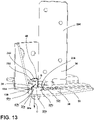
- the lower hinge support 36 is also configured to be retained in an intermediate position ( FIG. 13 ) to place the door 10 in a partially open position (not shown). It is contemplated that the door 10 may be retained in any number of intermediate positions based on the configuration of the pivot members 26, 38 without departing from the scope of the present disclosure.
- the first and second protrusions 28a, 28b of the first pivot member 26 include inclined surfaces 30a-30d.
- the second and fourth inclined surfaces 30b, 30d may be oriented at a first angle ⁇ relative to an interior surface 258 of the first pivot member 26.
- the first and third inclined surfaces 30a, 30c may be oriented at a second angle ⁇ relative to the interior surface 258 of the first pivot member 26.
- the angle ⁇ may be configured to be larger than the angle ⁇ .
- the angle ⁇ may be configured to be the same or substantially the same as angle ⁇ .
- the first and second protrusions 40a, 40b of the second pivot member 38 include inclined surfaces 42a-42d.
- the first and third inclined surfaces 42a, 42c may be configured as engagement surfaces and may be oriented at a first angle ⁇ ' relative to an interior surface 260 of the second pivot member 38.
- the second and fourth inclined surfaces 42b, 42d may be configured as retention surfaces and may be oriented at a second angle ⁇ ' relative to the interior surface 260 of the second pivot member 38.
- the angle ⁇ ' may be configured to be larger than the angle ⁇ '.
- the angle ⁇ ' may be configured to be the same or substantially the same as angle ⁇ '.
- angles ⁇ and ⁇ ' may be substantially the same size or may be different sizes, and it is further contemplated that the angles ⁇ and ⁇ ' may be substantially the same size or may be different sizes without departing from the scope of the present disclosure.
- the lower hinge support 36 is shown in the first position.
- the horizontal surface 32a of the first protrusion 28a of the first pivot member 26 is in contact with the horizontal surface 44a of the first protrusion 40a of the second pivot member 38.
- the horizontal surface 32b of the second protrusion 28b is also in contact with the horizontal surface 44b of the second protrusion 40b.
- the second pivot member 38 is rotated in a first direction (arrow A) from the first position ( FIG. 11 ) to an intermediate position ( FIG. 13 ).
- Each of the horizontal surfaces 44a, 44b of the first and second protrusions 40a, 40b of the second pivot member 38 is slidably engaged with the horizontal surface 32a, 32b of the corresponding protrusion of the first and second protrusions 28a, 28b of the first pivot member 26.
- the horizontal surfaces 44a, 44b are configured to slide along the corresponding horizontal surfaces 32a, 32b as the lower hinge support 36 is rotated from the first position into the intermediate position.
- each of the horizontal surfaces 44a, 44b is configured to slide along the corresponding horizontal surface 32a, 32b until one of the protrusions 40a, 40b is proximate the receiving well 190 of the first pivot member 26, as shown in FIG. 13 .
- the second inclined surface 42b of the first protrusion 40a of the second pivot member 38 slides downward to along arrow B to be in contact with the first inclined surfaces 30a of the first protrusion 28a of the first pivot member 26.
- first pivot member 26 may further define a second receiving well 190, as previously discussed, configured to receive the second protrusion 40b in the same or a similar manner such that the fourth inclined surface 42d of the second protrusion 40b slides into contact with the third inclined surface 30c of the second protrusion 28b.
- the receiving wells 190, 220 and protrusions 28a, 28b and 40a, 40b may be configured such that the first and third inclined surfaces 42a, 42c of the protrusions 40a, 40b of the second pivot member 38 are in contact with the second and fourth inclined surfaces 30b, 30d of the corresponding protrusion 28a, 28b of first pivot member 26.
- the receiving wells 190, 220 and protrusions 28a, 28b and 40a, 40b may be configured such that the first and third inclined surfaces 42a, 42c of the protrusions 40a, 40b of the second pivot member 38 are spaced apart from the second and further inclined surfaces 30b, 30d of the protrusions 28a, 28b of the first pivot member 26.
- the lower hinge support 36 and the second pivot member 38 are further rotatable in the first direction (see arrow A of FIG. 12 ) to move the lower hinge support 36 from the intermediate position to the second position, as shown in FIG. 14 .
- the second pivot member 38 in conjunction with the lower hinge support 36, is rotatable another 180 degrees along in the first direction such that the second protrusion 40b of the second pivot member 38 is received within the receiving well 190.
- the first and third inclined surfaces 42a, 42c of the first and second protrusions 40a, 40b of the second pivot member 38 slide upward along the second and fourth inclined surfaces 30b, 30d of the first or second protrusion 28a, 28b of the first pivot member 26 until the horizontal surfaces 44a, 44b of the second pivot member 38 are in slidable contact corresponding horizontal surfaces 32a, 32b of the first pivot member 26.
- the lower hinge support 36 is further rotated in the first direction until the second protrusion 40b is received by the receiving well 190 of the first pivot member 26, as shown in FIG. 14 .
- the angles ⁇ and ⁇ ' are sized to create a lower slope along the engagement surfaces and facilitate rotation of the second pivot member 38 in the first direction, and the angles ⁇ and ⁇ ' are sized to allow the retention surfaces to act as stops and require a larger force to rotate the second pivot member 38 in a second direction opposite the first direction, as shown by arrow D of FIG. 14 .
- the fourth inclined surface 42d is in contact with the first inclined surface 30a of the first protrusion 28a of the first pivot member 26 such that the lower hinge support 36 and the second pivot member 38 are substantially retained in the second position.
- a force F must be applied to overcome the contact between the fourth inclined surface 42d and the first inclined surface 30a and rotate the lower hinge support 36 and the second pivot member 38 in the second direction.
- an appliance includes a door having a plurality of panels spaced apart by a vertical support.
- a lower hinge mount is coupled with an appliance body.
- a first pivot member is coupled with the lower hinge mount and defines a first pin receptacle.
- the first pivot member includes a first protrusion having a first inclined surface and a first horizontal surface.
- a lower hinge support is fixedly coupled with the vertical support and is rotatable between first and second positions relative to the first pivot member.
- a second pivot member is coupled with the lower hinge support and defines a second pin receptacle.
- the second pivot member includes a second protrusion having a second inclined surface and a second horizontal surface. The second horizontal surface contacts the first horizontal surface in the first position.
- a lower hinge pin is coupled with the lower hinge support and is vertically translated within the first and second pin receptacles when the second pivot member moves from the first position to the second position.
- first and second positions of a lower hinge support correspond with closed and open positions of a door, respectively.
- a second inclined surface of a second protrusion contacts a first inclined surface of a first protrusion in a second position.
- an appliance includes an upper hinge mount coupled with an appliance body, an upper hinge support fixedly coupled with a vertical support, and an upper hinge pin extending downward from the upper hinge mount.
- the upper hinge support is rotatable about the upper hinge pin.
- a door is rotatable about a vertical axis extending between upper and lower hinge pins.
- a second pivot member includes a linear edge defining a receiving well, and a lower hinge support includes a stop configured to be received within the receiving well and abut the linear edge.
- a first protrusion of a first pivot member at least partially defines a receiving space, and a second protrusion is received by the receiving space when a second pivot member is in a second position.
- a lower hinge mount is coupled with a bottom panel of the appliance body.
- an appliance includes a door rotatable between open and closed positions.
- a lower hinge mount is coupled with an appliance body.
- a first pivot member is coupled with the lower hinge mount and defines a first pin receptacle.
- the first pivot member includes a first protrusion having a first inclined surface and a first horizontal surface.
- a second pivot member defines a second pin receptacle aligned with the first pin receptacle and includes a second protrusion having a second inclined surface and a second horizontal surface.
- the second pivot member is rotatable relative to the first pivot member between first and second positions.
- the second horizontal surface contacts the first horizontal surface in the first position, and the second inclined surface contacts the first inclined surface in the second position.
- a lower hinge pin is coupled with the second pivot member to rotate with the second pivot member.
- the lower hinge pin is vertically translated through the first and second pin receptacles when the second pivot member moves from the first position to the second position.
- an appliance includes a lower hinge support coupled with a door and defining a support pin receptacle aligned with first and second pin receptacles.
- the support pin receptacle is at least partially defined by an interior linear edge of the lower hinge support.
- a lower hinge pin includes a central portion having a linear side and extending from a body. The central portion is received by a support pin receptacle and the linear side is in contact with an interior linear edge of a lower hinge support to couple the lower hinge pin to rotate with the lower hinge support.
- a body of a lower hinge pin is received by and vertically translatable through first and second pin receptacles.
- a lower hinge support includes a stop, and a second pivot member defines a receiving space. The stop is received by the receiving space to fixedly couple the second pivot member with the lower hinge support.
- a lower hinge mount includes a foot coupled with a bottom panel of an appliance body.
- first and second positions of a second pivot member correspond with closed and open positions of a door, respectively.
- a lower hinge assembly for an appliance door includes a lower pivot member coupled with a hinge mount and defining a first pin receptacle.
- the lower pivot member includes a lower protrusion having first and second inclined surfaces extending from a first horizontal surface.
- An upper pivot member defines a second pin receptacle aligned with the first pin receptacle and includes an upper protrusion having third and fourth inclined surfaces and a second horizontal surface.
- the upper pivot member is rotatable between first and second positions relative to the lower pivot member.
- the second horizontal surface is in contact with the first horizontal surface in the first position
- the third inclined surface is in contact with the second inclined surface in the second position.
- a lower hinge pin extends through the first and second pin receptacles and is coupled to rotate in conjunction with the upper pivot member.
- the lower hinge pin is vertically translated within the first and second pin receptacles when the upper pivot member moves from the first position to the second position.
- an upper pivot member is rotatable into an intermediate position between first and second positions, and a fourth inclined surface is in contact with a first inclined surface in the intermediate position.
- a first inclined surface is oriented at a first angle relative to an interior surface of a lower pivot member, and a fourth inclined surface is oriented at a second angle relative to an interior surface of an upper pivot member.
- the first angle is substantially the same as the second angle.
- a lower pivot member defines a receiving well and a second protrusion of an upper pivot member is received by the receiving well in a second position.
- a lower hinge assembly includes a lower hinge support including a stop.
- An upper pivot member defines a receiving space, and the stop is received by the receiving space to fixedly couple the upper pivot member with the lower hinge support.
- the term "coupled” in all of its forms, couple, coupling, coupled, etc. generally means the joining of two components (electrical or mechanical) directly or indirectly to one another. Such joining may be stationary in nature or movable in nature. Such joining may be achieved with the two components (electrical or mechanical) and any additional intermediate members being integrally formed as a single unitary body with one another or with the two components. Such joining may be permanent in nature or may be removable or releasable in nature unless otherwise stated.
- elements shown as integrally formed may be constructed of multiple parts or elements shown as multiple parts may be integrally formed, the operation of the interfaces may be reversed or otherwise varied, the length or width of the structures and/or members, or connector, or other elements of the system may be varied, the nature or number of adjustment positions provided between the elements may be varied.
- the elements and/or assemblies of the system may be constructed from any of a wide variety of materials that provide sufficient strength or durability, in any of a wide variety of colors, textures, and combinations. Accordingly, all such modifications are intended to be included within the scope of the present innovations. Other substitutions, modifications, changes, and omissions may be made in the design, operating conditions, and arrangement of the desired and other exemplary embodiments without departing from the spirit of the present innovations.
Landscapes
- Engineering & Computer Science (AREA)
- Mechanical Engineering (AREA)
- Hinges (AREA)
- Pivots And Pivotal Connections (AREA)
Abstract
An appliance (12) includes a door (10) with a plurality of panels (14, 16) spaced apart by a vertical support (18, 20) and a lower hinge mount (22) coupled with an appliance body (24). A first pivot member (26) is coupled with the lower hinge mount (22) and defines a first pin receptacle (34), the first pivot member (26) includes a first protrusion (28a, 28b) with a first inclined surface (30a-30d) and a first horizontal surface (32a, 32b). A lower hinge support (36) is fixedly coupled with the vertical support (18, 20) and rotatable between first and second positions relative to the first pivot member (26). A second pivot member (38) is coupled with the lower hinge support (36) and defines a second pin receptacle (46). The second pivot member (38) includes a second protrusion (40a, 40b) with a second inclined surface (42a-42d) and a second horizontal surface (44a, 44b). The second horizontal surface (44a, 44b) contacts the first horizontal surface (32a, 32b) in the first position. A lower hinge pin (48) is coupled with the lower hinge support (36) and vertically translated within the first pin receptacle (34) when the second pivot member (38) moves from the first position to the second position. The second pivot member (38) defines a receiving space (226) and the lower hinge support (36) includes a stop (214) monolithic with the lower hinge support (36). The stop (214) extends toward the second pivot member (38) and is received within the receiving space (226) to non-rotatably couple the second pivot member (38) with the lower hinge support (36).
Description
- The present disclosure generally relates to a hinge assembly for an appliance door, and more specifically, to a self-retaining hinge assembly for an appliance door.
- Hinge assemblies are used on appliances to rotatably couple doors with cabinets. In various situations, the door may include a mechanism for retaining the door in an open position.
- According to one aspect of the present disclosure, an appliance includes a door with a plurality of panels spaced apart by a vertical support and a lower hinge mount coupled with an appliance body. A first pivot member is coupled with the lower hinge mount and defines a first pin receptacle. The first pivot member includes a first protrusion that has a first inclined surface and a first horizontal surface. A lower hinge support is fixedly coupled with the vertical support and rotatable between first and second positions relative to the first pivot member. A second pivot member is coupled with the lower hinge support and defines a second pin receptacle. The second pivot member includes a second protrusion that has a second inclined surface and a second horizontal surface. The second horizontal surface contacts the first horizontal surface in the first position. A lower hinge pin is coupled with the lower hinge support and is vertically translated within the first pin receptacle when the second pivot member moves from the first position to the second position. The second pivot member defines a receiving space and the lower hinge support includes a stop monolithic with the lower hinge support. The stop extends toward the second pivot member and is received within the receiving space to non-rotatably couple the second pivot member with the lower hinge support.
- According to another aspect of the present disclosure, an appliance includes a door rotatable between open and closed positions. A lower hinge mount is coupled with an appliance body. A first pivot member is coupled with the lower hinge mount and defines a first pin receptacle. The first pivot member includes a first protrusion having a first inclined surface and a first horizontal surface. A second pivot member defines a second pin receptacle aligned with the first pin receptacle and includes a second protrusion having a second inclined surface and a second horizontal surface. The second pivot member is rotatable relative to the first pivot member between first and second positions. The second horizontal surface contacts the first horizontal surface in the first position, and the second inclined surface contacts the first inclined surface in the second position. A lower hinge pin is coupled with the second pivot member to rotate with the second pivot member. The lower hinge pin is vertically translated through the first and second pin receptacles when the second pivot member moves from the first position to the second position.
- According to yet another aspect of the present disclosure, a lower hinge assembly for an appliance door includes a lower pivot member coupled with a hinge mount and defining a first pin receptacle. The lower pivot member includes a lower protrusion having first and second inclined surfaces extending from a first horizontal surface. An upper pivot member defines a second pin receptacle aligned with the first pin receptacle and includes an upper protrusion having third and fourth inclined surfaces and a second horizontal surface. The upper pivot member is rotatable between first and second positions relative to the lower pivot member. The second horizontal surface is in contact with the first horizontal surface in the first position, and the third inclined surface is in contact with the second inclined surface in the second position. A lower hinge pin extends through the first and second pin receptacles and is coupled to rotate in conjunction with the upper pivot member. The lower hinge pin is vertically translated within the first and second pin receptacles when the upper pivot member moves from the first position to the second position.
- These and other features, advantages, and objects of the present disclosure will be further understood and appreciated by those skilled in the art by reference to the following specification, claims, and appended drawings.
- In the drawings:
-
FIG. 1 is a side perspective view of an oven appliance including top and bottom doors, according to various examples; -
FIG. 2 is a partial side perspective view of the oven appliance ofFIG. 1 with the top door removed; -
FIG. 3 is a partial side profile view of the oven appliance ofFIG. 2 with an outer side panel removed; -
FIG. 4 is a partial front perspective view of the oven appliance ofFIG. 1 illustrating an upper hinge assembly of the bottom door when the bottom door is in an open position; -
FIG. 5 is a partial front perspective view of the oven appliance and upper hinge assembly ofFIG. 4 with the bottom door removed; -
FIG. 6 is a partial front perspective view of the oven appliance ofFIG. 1 illustrating a lower hinge assembly of the bottom door with the bottom door removed; -
FIG. 7 is an exploded view of the lower hinge assembly ofFIG. 6 ; -
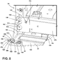
FIG. 8 is a partial front perspective view of a first portion of the lower hinge assembly ofFIG. 6 coupled with the appliance; -
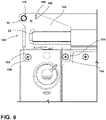
FIG. 9 is a bottom elevation view of the lower hinge assembly ofFIG. 8 ; -
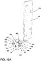
FIG. 10A is a first side perspective view of a second portion of the bottom hinge assembly ofFIG. 6 ; -
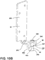
FIG. 10B is a second side perspective view of the second portion of the bottom hinge assembly ofFIG. 10A ; -
FIG. 11 is a side perspective view of the lower hinge assembly ofFIG. 6 removed from the appliance and in a first position; -
FIG. 12 is a side perspective view of the lower hinge assembly ofFIG. 11 in an intermediate position; -
FIG. 13 is a side perspective view of the lower hinge assembly ofFIG. 11 in an intermediate position; and; -
FIG. 14 is a side perspective view of the lower hinge assembly ofFIG. 11 in a second position. - The components in the figures are not necessarily to scale, emphasis instead being placed upon illustrating the principles described herein.
- The present illustrated embodiments reside primarily in combinations of method steps and apparatus components related to a hinge assembly for an appliance door. Accordingly, the apparatus components and method steps have been represented, where appropriate, by conventional symbols in the drawings, showing only those specific details that are pertinent to understanding the embodiments of the present disclosure so as not to obscure the disclosure with details that will be readily apparent to those of ordinary skill in the art having the benefit of the description herein. Further, like numerals in the description and drawings represent like elements.
- For purposes of description herein, the terms "upper," "lower," "right," "left," "rear," "front," "vertical," "horizontal," and derivatives thereof shall relate to the disclosure as oriented in
FIG. 1 . Unless stated otherwise, the term "front" shall refer to the surface of the element closer to an intended viewer, and the term "rear" shall refer to the surface of the element further from the intended viewer. However, it is to be understood that the disclosure may assume various alternative orientations, except where expressly specified to the contrary. It is also to be understood that the specific devices and processes illustrated in the attached drawings, and described in the following specification are simply exemplary embodiments of the inventive concepts defined in the appended claims. Hence, specific dimensions and other physical characteristics relating to the embodiments disclosed herein are not to be considered as limiting, unless the claims expressly state otherwise. - The terms "including," "comprises," "comprising," or any other variation thereof, are intended to cover a non-exclusive inclusion, such that a process, method, article, or apparatus that comprises a list of elements does not include only those elements but may include other elements not expressly listed or inherent to such process, method, article, or apparatus. An element proceeded by "comprises a ... " does not, without more constraints, preclude the existence of additional identical elements in the process, method, article, or apparatus that comprises the element.
- Referring to
FIGS. 1-14 ,reference numeral 10 generally designates door, referred to also as thebottom door 10 of theexemplary appliance 12 illustrated herein. Thebottom door 10 includes a plurality ofpanels vertical supports lower hinge mount 22 is coupled with anappliance body 24. Afirst pivot member 26 is coupled with thelower hinge mount 22 and includes afirst protrusion first protrusion inclined surface 30a-30d and ahorizontal surface first pin receptacle 34 defined by thefirst pivot member 26. Alower hinge support 36 is fixedly coupled with thevertical support second pivot member 38 is coupled with thelower hinge support 36. Thelower hinge support 36 is rotatable relative to thefirst pivot member 26 between a first position (FIG. 11 ) and a second position (FIG. 14 ). Thesecond pivot member 38 includes asecond protrusion inclined surface 42a-42d and ahorizontal surface second protrusion second pin receptacle 46 defined by thesecond pivot member 38. Thehorizontal surface second protrusion horizontal surface first protrusion lower hinge support 36 is in the first position, and theinclined surface 42a-42d of thesecond protrusion inclined surface 30a-30d of thefirst protrusion lower hinge pin 48 extends through the first andsecond pin receptacles lower hinge pin 48 is fixedly coupled with thelower hinge support 36 and is vertically translated within the first andsecond pin receptacles second pivot member 38 moves from the first position to the second position. - Referring now to
FIGS. 1 and2 , theappliance 12 is illustrated including theappliance body 24 defining atop cavity 74 and abottom cavity 76. Theappliance body 24 includes first andsecond side panels top panel 64, abottom panel 66, and arear panel 68, and afront panel 70. In various examples, thetop cavity 74 and thebottom cavity 76 may be defined byliners appliance body 24. It will be understood that theappliance body 24 encloses components typically found in a conventional cooking oven, such as electrical components, heating elements, gas lines, valves, control units, burner elements, broiled elements, and the like. Such components will not be described further herein except where necessary for a complete understanding of the aspects of the present disclosure. - As illustrated in
FIG. 1 , atop door 92 is positioned to selectively seal thetop cavity 74, and thebottom door 10 is positioned to selectively seal thebottom cavity 76. Each of thedoors appliance body 24 and movable between an open position and a closed position.Handles 94 may be coupled to each of thedoors respective door top door 92 is rotatable about a horizontal axis X between the open and closed positions. - The
bottom door 10 is positioned below thetop door 92 and is hingedly coupled with the appliance by upper andlower hinge assemblies bottom door 10 is configured to be rotated about a vertical axis Y extending through theupper hinge assembly 98 and thelower hinge assembly 100 of thebottom door 10. The remainder of the disclosure is directed to thebottom door 10, the upper andlower hinge assemblies bottom door 10 with theappliance body 24, and the features directly relevant to these components. It will be understood that, while thetop door 92 is illustrated with a different configuration, thetop door 92 may be modified such that the same features described with respect to thebottom cavity 76 and thebottom door 10 may be applied to both the top andbottom doors - Referring to
FIGS. 2 and3 , thebottom door 10 includes a plurality ofdoor panels outer door panel 14 and aninner door panel 16. Thedoor panels vertical supports door 10. The pair ofvertical supports inner door panels door 10. It is also contemplated that one or all of the panels, including one or both of the outer andinner door panels vertical support 18 positioned proximate the hinge axis Y of thedoor 10 is configured to be coupled with the upper andlower hinge assemblies bottom door 10 to hingedly couple thedoor 10 with theappliance 12, as described in more detail elsewhere herein. - Referring now to
FIGS. 3 and4 , theupper hinge assembly 98 is illustrated coupled with thedoor 10 and theappliance body 24. As best shown inFIG. 4 , theupper hinge assembly 98 includes anupper hinge mount 110 having afirst portion 112 and asecond portion 114. Thesecond portion 114 extends substantially perpendicular from thefirst portion 112. Thefirst portion 112 is configured to be coupled with thefront panel 70 of theappliance body 24 such that thesecond portion 114 extends forward of thefront panel 70. In various examples, thefront panel 70 of theappliance body 24 may define arecess 118 configured to receive thefirst portion 112 of theupper hinge mount 110. A plurality offasteners 120 may be used to couple thefirst portion 112 with thefront panel 70. - Referring now to
FIGS. 4 and5 , thesecond portion 114 extends forward from thefront panel 70 and defines a receivingspace 124 configured to receive anupper hinge pin 128. Theupper hinge pin 128 is fixedly coupled with thesecond portion 114 of theupper hinge mount 110 and extends downward from thesecond portion 114. Theupper hinge pin 128 is further configured to be received by a receiving well 132 of anupper hinge support 134. The receiving well 132 may have a smaller diameter than the receivingspace 124 to securely couple theupper hinge pin 128 with thesecond portion 114 such that theupper hinge support 134 is rotatable about theupper hinge pin 128. - As best shown in
FIG. 5 , theupper hinge support 134 includes anelongated coupling plate 138 extending from ahinge arm 140. Thecoupling plate 138 may be substantially rectangular in shape or may have any other elongated shape. Thecoupling plate 138 of theupper hinge support 134 is configured to be aligned with and coupled to thevertical support 18 by a plurality offasteners 142 such that theupper hinge support 134 rotates about theupper hinge pin 128 as thedoor 10 moves between the open and closed positions. Thehinge arm 140 may be positioned substantially perpendicular to thecoupling plate 138 and defines the receiving well 132 of theupper hinge support 134 to receive theupper hinge pin 128 to facilitate the rotation of theupper hinge support 134. - Referring now to
FIGS. 3 and6 , thelower hinge assembly 100 is illustrated coupled with the door 10 (FIG. 3 ) and with the door removed (FIG. 6 ). As best shown inFIGS. 6 and7 , thelower hinge assembly 100 includes thelower hinge mount 22 coupled with afirst pivot member 26, also referred to herein as alower pivot member 26. Thelower hinge support 36 is rotatably coupled with thelower hinge mount 22. Asecond pivot member 38, also referred to herein as anupper pivot member 38, is coupled with thelower hinge support 36 and is configured to engage thefirst pivot member 26, as described in more detail elsewhere herein. - Referring now to
FIGS. 6-9 , thelower hinge mount 22 includes abase plate 150 extending at least partially forward of theappliance body 24. As best shown inFIGS. 7-9 , at least onefoot 154 is integrally formed with, and extends rearward from, thebase plate 150. It will be understood that thelower hinge mount 22 may include any number offeet 154 without departing from the scope of the present disclosure. Eachfoot 154 is configured to be coupled with thebottom panel 66 of theappliance body 24 by afastener 156. As shown inFIGS. 8 and9 , eachfoot 154 may include astep 158 to vertically offset thebase plate 150 from thebottom panel 66. - Referring now to
FIGS. 6-8 , thelower hinge mount 22 further includes aside wall 162 integrally formed with, and extending upward from, thebase plate 150. A mountingflange 166 extends perpendicularly from theside wall 162. When the at least onefoot 154 is coupled with thebottom panel 66 of theappliance body 24, the mountingflange 166 is aligned with thefront panel 70 and alower support 170 of theappliance body 24. The mountingflange 166 defines a plurality of receivingspaces 168 configured to align with through-holes 174 of thelower support 170. As best shown inFIG. 6 , a plurality offasteners 172 is configured to couple the mountingflange 166 with thelower support 170 and thefront panel 70. - As best shown in
FIG. 7 , thebase plate 150 defines amount pin receptacle 176 configured to at least partially receive thelower hinge pin 48, as described in more detail elsewhere herein. Themount pin receptacle 176 is defined proximate theside wall 162 and a forward edge of thebase plate 150. Thebase plate 150 further defines amount aperture 180 proximate themount pin receptacle 176 and the forward edge of thebase plate 150. - As best shown in
FIGS. 7 and8 , thefirst pivot member 26 may be generally oblong and is configured to be coupled with thebase plate 150. Thefirst pivot member 26 defines amember aperture 184 at a first end of thefirst pivot member 26. Themember aperture 184 is configured to align with themount aperture 180 of thebase plate 150. Afastener 186 is positioned through theapertures first pivot member 26 with thebase plate 150. - The
first pivot member 26 further defines thefirst pin receptacle 34 at a second end of thefirst pivot member 26. Thefirst pin receptacle 34 is aligned with themount pin receptacle 176 when thefastener 186 is positioned through theapertures first pin receptacle 34 is also configured to at least partially receive thelower hinge pin 48, as described in more detail elsewhere herein. - As best shown in
FIG. 8 , thefirst pivot member 26 includes upwardly extendingprotrusions first pin receptacle 34. As illustrated, the upwardly extendingprotrusions first protrusion 28a and asecond protrusion 28b. Thefirst protrusion 28a includes a firstinclined surface 30a and a secondinclined surface 30b, and thesecond protrusion 28b includes a thirdinclined surface 30c and a fourthinclined surface 30d. Theinclined surfaces 30a-30d extend downward and outward from a correspondinghorizontal surface second protrusion second protrusions - Referring now to
FIGS. 10A and10B , thelower hinge assembly 100 further includes thelower hinge support 36. Thelower hinge support 36 includes anelongated coupling plate 200 integrally formed with ahinge arm 202. Thecoupling plate 200 may be substantially rectangular in shape or may have any other elongated shape. As shown inFIG. 3 , thecoupling plate 200 of thelower hinge support 36 is configured to be aligned with, and coupled with, thevertical support 18 by a plurality offasteners 204 such that thelower hinge support 36 rotates about thelower hinge pin 48 as thedoor 10 moves between the open and closed positions. Theupper hinge support 134 may be coupled at an upper end of thevertical support 18, and thelower hinge support 36 may be coupled at a lower, opposite end of thevertical support 18. The lower and upper hinge supports 36, 134 are rotatable simultaneously and in conjunction with thevertical support 18 to rotate thedoor 10 between open and closed positions. - Referring again to
FIGS. 10A and10B , thehinge arm 202 may be positioned substantially perpendicular to thecoupling plate 200 and defines asupport pin receptacle 208. Thesupport pin receptacle 208 is configured to be aligned with at least themount pin receptacle 176 and thefirst pin receptacle 34 and is configured to at least partially received thelower hinge pin 48. - As best shown in
FIG. 7 , thehinge arm 202 includes an interiorlinear edge 210. The interiorlinear edge 210 at least partially defines thesupport pin receptacle 208 and is configured to maintain the position of thelower hinge pin 48 within thesupport pin receptacle 208, as discussed in more detail elsewhere herein. In other words, the interiorlinear edge 210 is configured such that thelower hinge pin 48 is rotationally fixed (i.e., not rotatable) within thesupport pin receptacle 208. - Referring now to
FIGS. 7 and10A , thelower hinge support 36 further includes astop 214 extending outward and at least partially downward from thehinge arm 202. Thestop 214 includes at least onelinear side 216. In other words, thestop 214 may have a singlelinear side 216 or may have a pair of opposinglinear sides 216. Eachlinear side 216 is configured to be engaged with and contact a portion of thesecond pivot member 38 to retain the position of thesecond pivot member 38 relative to thelower hinge support 36. - As previously introduced, the
second pivot member 38 is coupled with thelower hinge support 36. Thesecond pivot member 38 includes one or morelinear edges 230 extending radially along thesecond pivot member 38 and at least partially defining a receivingspace 226. The receivingspace 226 is configured to receive thestop 214 of thelower hinge support 36. When thestop 214 is received by the receivingspace 226, thelinear edge 230 of thesecond pivot member 38 is in contact with thelinear side 216 of thestop 214. The contact between thelinear side 216 and thelinear edge 230 facilitates rotation of thesecond pivot member 38 in conjunction with thelower hinge support 36. - Referring again to
FIGS. 10A and10B , thesecond pivot member 38 includes downwardly extendingprotrusions second pin receptacle 46. As illustrated, the downwardly extendingprotrusions first protrusion 40a and asecond protrusion 40b. Thefirst protrusion 40a includes a firstinclined surface 42a and a secondinclined surface 42b, and thesecond protrusion 40b includes a thirdinclined surface 42c and a fourthinclined surface 42d. Theinclined surfaces 42a-42d extend downward and outward from a correspondinghorizontal surface second protrusion second protrusions lea 220. - As best shown in
FIG. 7 , thelower hinge assembly 100 further includes thelower hinge pin 48 including acoupling end 240 integrally formed with and extending from acentral portion 246. Thecoupling end 240 is configured to extend past thesupport pin receptacle 208 of thehinge arm 202 of thelower hinge support 36 and engage with anut 242. Thecentral portion 246 is configured to be received by thesupport pin receptacle 208 and includes at least onelinear surface 248. Thelinear surface 248 is configured to be engaged with the interiorlinear edge 210 of thehinge arm 202. The engagement between the interiorlinear edge 210 and thelinear surface 248 guides the insertion of thelower hinge pin 48 into thesupport pin receptacle 208. The engagement further acts to fixedly couple thelower hinge pin 48 with thesecond pivot member 38 such that thelower hinge pin 48 and thesecond pivot member 38 rotate in conjunction with thelower hinge support 36. - The
lower hinge pin 48 further includes abody 252. Thebody 252 is configured to extend through the first andsecond pin receptacles mount pin receptacle 176. Thebody 252 includes a substantially cylindrical shape such that thebody 252 is rotatable within thereceptacles body 252 is further configured to be vertically translated through thereceptacles lower hinge support 36 is moved from the first position to the second position, as discussed in more detail elsewhere below. In other words, thebody 252 of thelower hinge pin 48 is vertically translatable within the first andsecond pin receptacles mount pin receptacle 176. - In operation, the
second pivot member 38, and thelower hinge pin 48 are rotated with thelower hinge support 36 to rotate thedoor 10 from an open position to a closed position. The first position of the lower hinge support 36 (FIG. 11 ) corresponds with the closed position of thedoor 10 and the second position of the lower hinge support 36 (FIG. 14 ) corresponds with the open position of thedoor 10. As illustrated, thelower hinge support 36 is also configured to be retained in an intermediate position (FIG. 13 ) to place thedoor 10 in a partially open position (not shown). It is contemplated that thedoor 10 may be retained in any number of intermediate positions based on the configuration of thepivot members - Referring now to
FIGS. 10A-11 , the first andsecond protrusions first pivot member 26 includeinclined surfaces 30a-30d. The second and fourthinclined surfaces interior surface 258 of thefirst pivot member 26. The first and thirdinclined surfaces interior surface 258 of thefirst pivot member 26. The angle α may be configured to be larger than the angle β. Alternatively, the angle α may be configured to be the same or substantially the same as angle β. - The first and
second protrusions second pivot member 38 includeinclined surfaces 42a-42d. The first and thirdinclined surfaces interior surface 260 of thesecond pivot member 38. The second and fourthinclined surfaces interior surface 260 of thesecond pivot member 38. The angle α' may be configured to be larger than the angle β'. Alternatively, the angle α' may be configured to be the same or substantially the same as angle β'. It is contemplated that the angles α and α' may be substantially the same size or may be different sizes, and it is further contemplated that the angles β and β' may be substantially the same size or may be different sizes without departing from the scope of the present disclosure. - Referring now to
FIG. 11 , thelower hinge support 36 is shown in the first position. Thehorizontal surface 32a of thefirst protrusion 28a of thefirst pivot member 26 is in contact with thehorizontal surface 44a of thefirst protrusion 40a of thesecond pivot member 38. In the first position, thehorizontal surface 32b of thesecond protrusion 28b is also in contact with thehorizontal surface 44b of thesecond protrusion 40b. - As best shown in
FIG. 12 , thesecond pivot member 38 is rotated in a first direction (arrow A) from the first position (FIG. 11 ) to an intermediate position (FIG. 13 ). Each of thehorizontal surfaces second protrusions second pivot member 38 is slidably engaged with thehorizontal surface second protrusions first pivot member 26. Thehorizontal surfaces horizontal surfaces lower hinge support 36 is rotated from the first position into the intermediate position. - Referring now to
FIGS. 12 and13 , each of thehorizontal surfaces horizontal surface protrusions first pivot member 26, as shown inFIG. 13 . As illustrated, when thefirst protrusion 40a overlaps the receiving well 190, the secondinclined surface 42b of thefirst protrusion 40a of thesecond pivot member 38 slides downward to along arrow B to be in contact with the firstinclined surfaces 30a of thefirst protrusion 28a of thefirst pivot member 26. It will be understood that thefirst pivot member 26 may further define a second receiving well 190, as previously discussed, configured to receive thesecond protrusion 40b in the same or a similar manner such that the fourthinclined surface 42d of thesecond protrusion 40b slides into contact with the thirdinclined surface 30c of thesecond protrusion 28b. - As shown in
FIG. 13 , in the intermediate position, at least one of theprotrusions second pivot member 38 is received by a receiving well 190 of thefirst pivot member 26. Likewise, at least one of theprotrusions first pivot member 26 is received by a receiving well 220 of thesecond pivot member 38. When theprotrusions wells lower hinge pin 48 is vertically translated downward along arrow C. The receivingwells protrusions inclined surfaces protrusions second pivot member 38 are in contact with the second and fourthinclined surfaces corresponding protrusion first pivot member 26. Alternatively, the receivingwells protrusions inclined surfaces protrusions second pivot member 38 are spaced apart from the second and further inclinedsurfaces protrusions first pivot member 26. - The
lower hinge support 36 and thesecond pivot member 38 are further rotatable in the first direction (see arrow A ofFIG. 12 ) to move thelower hinge support 36 from the intermediate position to the second position, as shown inFIG. 14 . In other words, thesecond pivot member 38, in conjunction with thelower hinge support 36, is rotatable another 180 degrees along in the first direction such that thesecond protrusion 40b of thesecond pivot member 38 is received within the receiving well 190. When thesecond pivot member 38 is rotated from the intermediate position in the first direction, the first and thirdinclined surfaces second protrusions second pivot member 38 slide upward along the second and fourthinclined surfaces second protrusion first pivot member 26 until thehorizontal surfaces second pivot member 38 are in slidable contact correspondinghorizontal surfaces first pivot member 26. - The
lower hinge support 36 is further rotated in the first direction until thesecond protrusion 40b is received by the receiving well 190 of thefirst pivot member 26, as shown inFIG. 14 . The angles α and α' are sized to create a lower slope along the engagement surfaces and facilitate rotation of thesecond pivot member 38 in the first direction, and the angles β and β' are sized to allow the retention surfaces to act as stops and require a larger force to rotate thesecond pivot member 38 in a second direction opposite the first direction, as shown by arrow D ofFIG. 14 . When thesecond protrusion 40b is received by the receiving well 190 of thefirst pivot member 26, the fourthinclined surface 42d is in contact with the firstinclined surface 30a of thefirst protrusion 28a of thefirst pivot member 26 such that thelower hinge support 36 and thesecond pivot member 38 are substantially retained in the second position. To move thelower hinge support 36 and thesecond pivot member 38 back to the first position, and to move thedoor 10 into the closed position, a force F must be applied to overcome the contact between the fourthinclined surface 42d and the firstinclined surface 30a and rotate thelower hinge support 36 and thesecond pivot member 38 in the second direction. - According to one aspect, an appliance includes a door having a plurality of panels spaced apart by a vertical support. A lower hinge mount is coupled with an appliance body. A first pivot member is coupled with the lower hinge mount and defines a first pin receptacle. The first pivot member includes a first protrusion having a first inclined surface and a first horizontal surface. A lower hinge support is fixedly coupled with the vertical support and is rotatable between first and second positions relative to the first pivot member. A second pivot member is coupled with the lower hinge support and defines a second pin receptacle. The second pivot member includes a second protrusion having a second inclined surface and a second horizontal surface. The second horizontal surface contacts the first horizontal surface in the first position. A lower hinge pin is coupled with the lower hinge support and is vertically translated within the first and second pin receptacles when the second pivot member moves from the first position to the second position.
- According to another aspect, first and second positions of a lower hinge support correspond with closed and open positions of a door, respectively.
- According to another aspect, a second inclined surface of a second protrusion contacts a first inclined surface of a first protrusion in a second position.
- According to another aspect, an appliance includes an upper hinge mount coupled with an appliance body, an upper hinge support fixedly coupled with a vertical support, and an upper hinge pin extending downward from the upper hinge mount. The upper hinge support is rotatable about the upper hinge pin.
- According to another aspect, a door is rotatable about a vertical axis extending between upper and lower hinge pins.
- According to another aspect, a second pivot member includes a linear edge defining a receiving well, and a lower hinge support includes a stop configured to be received within the receiving well and abut the linear edge.
- According to another aspect, a first protrusion of a first pivot member at least partially defines a receiving space, and a second protrusion is received by the receiving space when a second pivot member is in a second position.
- According to another aspect, a lower hinge mount is coupled with a bottom panel of the appliance body.
- According to another aspect, an appliance includes a door rotatable between open and closed positions. A lower hinge mount is coupled with an appliance body. A first pivot member is coupled with the lower hinge mount and defines a first pin receptacle. The first pivot member includes a first protrusion having a first inclined surface and a first horizontal surface. A second pivot member defines a second pin receptacle aligned with the first pin receptacle and includes a second protrusion having a second inclined surface and a second horizontal surface. The second pivot member is rotatable relative to the first pivot member between first and second positions. The second horizontal surface contacts the first horizontal surface in the first position, and the second inclined surface contacts the first inclined surface in the second position. A lower hinge pin is coupled with the second pivot member to rotate with the second pivot member. The lower hinge pin is vertically translated through the first and second pin receptacles when the second pivot member moves from the first position to the second position.
- According to another aspect, an appliance includes a lower hinge support coupled with a door and defining a support pin receptacle aligned with first and second pin receptacles. The support pin receptacle is at least partially defined by an interior linear edge of the lower hinge support.
- According to another aspect, a lower hinge pin includes a central portion having a linear side and extending from a body. The central portion is received by a support pin receptacle and the linear side is in contact with an interior linear edge of a lower hinge support to couple the lower hinge pin to rotate with the lower hinge support.
- According to another aspect, a body of a lower hinge pin is received by and vertically translatable through first and second pin receptacles.
- According to another aspect, a lower hinge support includes a stop, and a second pivot member defines a receiving space. The stop is received by the receiving space to fixedly couple the second pivot member with the lower hinge support.
- According to another aspect, a lower hinge mount includes a foot coupled with a bottom panel of an appliance body.
- According to another aspect, first and second positions of a second pivot member correspond with closed and open positions of a door, respectively.
- According to another aspect, a lower hinge assembly for an appliance door includes a lower pivot member coupled with a hinge mount and defining a first pin receptacle. The lower pivot member includes a lower protrusion having first and second inclined surfaces extending from a first horizontal surface. An upper pivot member defines a second pin receptacle aligned with the first pin receptacle and includes an upper protrusion having third and fourth inclined surfaces and a second horizontal surface. The upper pivot member is rotatable between first and second positions relative to the lower pivot member. The second horizontal surface is in contact with the first horizontal surface in the first position, and the third inclined surface is in contact with the second inclined surface in the second position. A lower hinge pin extends through the first and second pin receptacles and is coupled to rotate in conjunction with the upper pivot member. The lower hinge pin is vertically translated within the first and second pin receptacles when the upper pivot member moves from the first position to the second position.
- According to another aspect, an upper pivot member is rotatable into an intermediate position between first and second positions, and a fourth inclined surface is in contact with a first inclined surface in the intermediate position.
- According to another aspect, a first inclined surface is oriented at a first angle relative to an interior surface of a lower pivot member, and a fourth inclined surface is oriented at a second angle relative to an interior surface of an upper pivot member. The first angle is substantially the same as the second angle.
- According to another aspect, a lower pivot member defines a receiving well and a second protrusion of an upper pivot member is received by the receiving well in a second position.
- According to another aspect, a lower hinge assembly includes a lower hinge support including a stop. An upper pivot member defines a receiving space, and the stop is received by the receiving space to fixedly couple the upper pivot member with the lower hinge support.
- It will be understood by one having ordinary skill in the art that construction of the described disclosure and other components is not limited to any specific material. Other exemplary embodiments of the disclosure disclosed herein may be formed from a wide variety of materials, unless described otherwise herein.
- For purposes of this disclosure, the term "coupled" (in all of its forms, couple, coupling, coupled, etc.) generally means the joining of two components (electrical or mechanical) directly or indirectly to one another. Such joining may be stationary in nature or movable in nature. Such joining may be achieved with the two components (electrical or mechanical) and any additional intermediate members being integrally formed as a single unitary body with one another or with the two components. Such joining may be permanent in nature or may be removable or releasable in nature unless otherwise stated.
- It is also important to note that the construction and arrangement of the elements of the disclosure as shown in the exemplary embodiments is illustrative only. Although only a few embodiments of the present innovations have been described in detail in this disclosure, those skilled in the art who review this disclosure will readily appreciate that many modifications are possible (e.g., variations in sizes, dimensions, structures, shapes and proportions of the various elements, values of parameters, mounting arrangements, use of materials, colors, orientations, etc.) without materially departing from the novel teachings and advantages of the subject matter recited. For example, elements shown as integrally formed may be constructed of multiple parts or elements shown as multiple parts may be integrally formed, the operation of the interfaces may be reversed or otherwise varied, the length or width of the structures and/or members, or connector, or other elements of the system may be varied, the nature or number of adjustment positions provided between the elements may be varied. It should be noted that the elements and/or assemblies of the system may be constructed from any of a wide variety of materials that provide sufficient strength or durability, in any of a wide variety of colors, textures, and combinations. Accordingly, all such modifications are intended to be included within the scope of the present innovations. Other substitutions, modifications, changes, and omissions may be made in the design, operating conditions, and arrangement of the desired and other exemplary embodiments without departing from the spirit of the present innovations.
- It will be understood that any described processes or steps within described processes may be combined with other disclosed processes or steps to form structures within the scope of the present disclosure. The exemplary structures and processes disclosed herein are for illustrative purposes and are not to be construed as limiting.
Claims (7)
- An appliance (12) comprising:a door (10) including a plurality of panels (14, 16) spaced apart by a vertical support (18, 20);a lower hinge mount (22) coupled with an appliance body (24);a first pivot member (26) coupled with the lower hinge mount (22) and defining a first pin receptacle (34), the first pivot member (26) including a first protrusion (28a, 28b) having a first inclined surface (30a-30d) and a first horizontal surface (32a, 32b);a lower hinge support (36) fixedly coupled with the vertical support (18, 20) and rotatable between first and second positions relative to the first pivot member (26);a second pivot member (38) coupled with the lower hinge support (36) and defining a second pin receptacle (46), the second pivot member (38) including a second protrusion (40a, 40b) having a second inclined surface (42a-42d) and a second horizontal surface (44a, 44b), wherein the second horizontal surface (44a, 44b) contacts the first horizontal surface (32a, 32b) in the first position; anda lower hinge pin (48) coupled with the lower hinge support (36) and vertically translated within the first pin receptacle (34) when the second pivot member (38) moves from the first position to the second position;wherein the second pivot member (38) defines a receiving space (226) and the lower hinge support (36) includes a stop (214) monolithic with the lower hinge support (36), wherein the stop (214) extends toward the second pivot member (38) and is received within the receiving space (226) to non-rotatably couple the second pivot member (38) with the lower hinge support (36).
- The appliance (12) of claim 1, wherein the first and second positions of the lower hinge support (36) correspond with closed and open positions of the door (10), respectively.
- The appliance (12) of either one of claims 1 or 2, wherein the second inclined surface (42a-42d) contacts the first inclined surface (30a-30d) in the second position.
- The appliance (12) of any one of claims 1-3, further comprising:an upper hinge mount (110) coupled with the appliance body (24);an upper hinge support (134) fixedly coupled with the vertical support (18, 20); andan upper hinge pin (128) extending downward from the upper hinge mount (110), wherein the upper hinge support (134) is rotatable about the upper hinge pin (128).
- The appliance (12) of claim 4, wherein the door (10) is rotatable about a vertical axis (Y) extending between the upper and lower hinge pins (128, 48).
- The appliance (12) of any one of claims 1-5, wherein the first protrusion (28a, 28b) of the first pivot member (26) at least partially defines a receiving well (132), and further wherein the second protrusion (40a, 40b) is received by the receiving well (132) when the second pivot member (38) is in the second position.
- The appliance (12) of any one of claims 1-6, wherein the lower hinge mount (22) is coupled with a bottom panel (66) of the appliance body (24).
Applications Claiming Priority (1)
| Application Number | Priority Date | Filing Date | Title |
|---|---|---|---|
| US17/117,442 US11236536B1 (en) | 2020-12-10 | 2020-12-10 | Appliance door hinge assembly |
Publications (1)
| Publication Number | Publication Date |
|---|---|
| EP4012143A1 true EP4012143A1 (en) | 2022-06-15 |
Family
ID=78821117
Family Applications (1)
| Application Number | Title | Priority Date | Filing Date |
|---|---|---|---|
| EP21212125.5A Withdrawn EP4012143A1 (en) | 2020-12-10 | 2021-12-02 | Appliance door hinge assembly |
Country Status (2)
| Country | Link |
|---|---|
| US (2) | US11236536B1 (en) |
| EP (1) | EP4012143A1 (en) |
Families Citing this family (2)
| Publication number | Priority date | Publication date | Assignee | Title |
|---|---|---|---|---|
| CN115807605A (en) * | 2021-09-15 | 2023-03-17 | 青岛海尔电冰箱有限公司 | Hinge and built-in refrigerator with the hinge |
| US20250354420A1 (en) * | 2024-05-17 | 2025-11-20 | Whirlpool Corporation | Household appliance |
Citations (6)
| Publication number | Priority date | Publication date | Assignee | Title |
|---|---|---|---|---|
| US3378881A (en) * | 1964-09-11 | 1968-04-23 | Stanley Works | Cafe hinge |
| US20050194875A1 (en) * | 2002-02-14 | 2005-09-08 | Reed William A. | Refrigeration unit |
| US20130154464A1 (en) * | 2011-12-15 | 2013-06-20 | Whirlpool Corporation | Cam plate for a door hinge assembly of a domestic refrigerator |
| WO2015031747A1 (en) * | 2013-08-29 | 2015-03-05 | Electrolux Home Products, Inc. | Hinge assembly for a refrigerator |
| US20160208531A1 (en) * | 2015-01-19 | 2016-07-21 | Kohler Co. | Shower door assemblies |
| US9834967B2 (en) * | 2015-12-15 | 2017-12-05 | Electrolux Home Products, Inc. | Hinge constructions |
Family Cites Families (46)
| Publication number | Priority date | Publication date | Assignee | Title |
|---|---|---|---|---|
| US753443A (en) * | 1904-03-01 | Self-locking hinge | ||
| US48264A (en) * | 1865-06-20 | Improvement in shutter-hinges | ||
| US208152A (en) * | 1878-09-17 | Improvement in lock-hinges | ||
| US606415A (en) * | 1898-06-28 | Taling | ||
| US2619673A (en) * | 1947-09-22 | 1952-12-02 | Fred S Evans | Three-piece hinge |
| US3131422A (en) * | 1961-03-01 | 1964-05-05 | Frank P Agius | Hinge for offset doors |
| US3113649A (en) * | 1962-05-23 | 1963-12-10 | Mills Company | Door assembly |
| US3398487A (en) * | 1966-09-16 | 1968-08-27 | Matyas John | Swinging door construction |
| US3628845A (en) * | 1970-05-11 | 1971-12-21 | Gen Electric | Refrigerator cabinet with self-closing door |
| US3722031A (en) * | 1971-04-20 | 1973-03-27 | Amana Refrigeration Inc | Door closing and check device for refrigerators, freezers and the like |
| US4090274A (en) * | 1976-12-20 | 1978-05-23 | Admiral Corporation | Gravity door closer |
| IT8424286U1 (en) | 1984-12-28 | 1986-06-28 | Nador Srl | Gravity-closing hinge structure for doors and the like |
| US5369842A (en) * | 1993-08-23 | 1994-12-06 | Whirlpool Corporation | "Hinge plate for a refrigerator" |
| SE509649C2 (en) | 1995-11-29 | 1999-02-22 | Torsby Verkstads Ab | hinge |
| US5788351A (en) | 1996-05-30 | 1998-08-04 | Prunty; Jeffrey L. | Cam for vertical adjustment of appliance doors |
| US6561180B1 (en) | 2002-01-15 | 2003-05-13 | Maytag Corporation | Oven door assembly |
| US6845545B2 (en) * | 2002-09-04 | 2005-01-25 | Samsung Electronics Co., Ltd. | Apparatus to close a door of a refrigerator |
| ITMI20030533U1 (en) | 2003-11-18 | 2005-05-19 | Candy Spa | APPLIANCES WITH DOOR SUPPORTED BY HIDDEN HINGE AND NORMAL AND BRAKED OPENING CORNER |
| US7111363B2 (en) * | 2004-02-26 | 2006-09-26 | Lotte Engineering & Machinery Mfg., Co., Ltd. | Door hinge structure for refrigerator |
| DE202004003997U1 (en) | 2004-03-15 | 2004-07-01 | BSH Bosch und Siemens Hausgeräte GmbH | A method for providing hinge adjustment to an oven door has a full height pivoting hinge bracket on the door and height adjustable fixed hinge brackets on the oven housing front corners |
| TWM281387U (en) * | 2005-08-17 | 2005-11-21 | Shin Zu Shing Co Ltd | Hinge having positioning and limiting functions |
| KR20080082848A (en) | 2007-03-09 | 2008-09-12 | 엘지전자 주식회사 | Hooded microwave oven |
| US7509709B2 (en) * | 2007-04-17 | 2009-03-31 | Shin Zu Shing Co., Ltd. | Hinge |
| US20090179539A1 (en) * | 2008-01-14 | 2009-07-16 | Dometic Ab | Refrigerator door stop |
| CN102365515B (en) * | 2009-02-27 | 2014-05-07 | 伊莱克斯家用产品公司 | Adjustable hinge for pivoting door |
| CN201568447U (en) * | 2009-10-30 | 2010-09-01 | 康准电子科技(昆山)有限公司 | Pivot device |
| KR101273825B1 (en) | 2011-07-21 | 2013-06-11 | 엘지전자 주식회사 | Door for oven |
| KR101295735B1 (en) * | 2011-09-16 | 2013-08-12 | 대영이앤비 주식회사 | The door hinge for a refrigerator |
| KR20130033068A (en) * | 2011-09-26 | 2013-04-03 | 삼성전자주식회사 | Refrigerator |
| US8544151B2 (en) * | 2011-11-22 | 2013-10-01 | Lang-Mekra North America, Llc | Engaging surfaces arrangement for a pivoting detent joint |
| KR20150016497A (en) * | 2012-05-03 | 2015-02-12 | 볼보 컨스트럭션 이큅먼트 에이비 | Apparatus for semi-automatically opening/closing door of construction equipment |
| US8721013B2 (en) * | 2012-06-08 | 2014-05-13 | Whirlpool Corporation | Grille cover assembly for domestic refrigerator |
| KR102030845B1 (en) * | 2012-11-13 | 2019-10-11 | 삼성전자주식회사 | Refrigerator and lower hinge module of the same |
| US9372001B2 (en) | 2013-09-06 | 2016-06-21 | Bsh Home Appliances Corporation | Home cooking appliance with a side swing oven door having an integral self capturing latch |
| US9395089B2 (en) | 2013-11-13 | 2016-07-19 | General Electric Company | Oven appliance and a hinge assembly for the same |
| US20150345203A1 (en) * | 2014-05-28 | 2015-12-03 | Nuova Star S.P.A. | Hinge for doors of electrical household appliances |
| KR20170127605A (en) | 2016-05-11 | 2017-11-22 | (주)토탈베이커리시스템 | Oven door hinge machine device |
| US9739523B1 (en) * | 2016-07-25 | 2017-08-22 | Haier Us Appliance Solutions, Inc. | Hinge assembly for a refrigerator appliance |
| KR102020537B1 (en) | 2017-08-07 | 2019-09-10 | 엘지전자 주식회사 | A Cooker Having a Door Capable of Being Opened Two Way |
| US10458164B2 (en) * | 2017-09-18 | 2019-10-29 | Haier Us Appliance Solutions, Inc. | Door hinge assembly for an appliance |
| CN110118465B (en) * | 2018-02-05 | 2022-05-10 | Bsh家用电器有限公司 | Household refrigeration appliances with specific height adjustment for doors |
| US10407958B1 (en) * | 2018-04-24 | 2019-09-10 | Kuo-Ho Tsou | Hinge device with a stop function |
| US11060333B2 (en) * | 2019-06-28 | 2021-07-13 | Whirlpool Corporation | Hinge assembly for a home appliance and method of assembling |
| US11326784B2 (en) * | 2019-06-28 | 2022-05-10 | Whirlpool Corporation | Mounting assembly for a door of a home appliance and method of use |
| US11015377B2 (en) * | 2019-08-26 | 2021-05-25 | Whirlpool Corporation | Hinge assembly |
| US12281797B2 (en) * | 2020-02-25 | 2025-04-22 | Whirlpool Corporation | Hinge assembly for an appliance door |
-
2020
- 2020-12-10 US US17/117,442 patent/US11236536B1/en not_active Expired - Fee Related
-
2021
- 2021-12-02 EP EP21212125.5A patent/EP4012143A1/en not_active Withdrawn
-
2022
- 2022-01-31 US US17/589,260 patent/US11661777B2/en active Active
Patent Citations (6)
| Publication number | Priority date | Publication date | Assignee | Title |
|---|---|---|---|---|
| US3378881A (en) * | 1964-09-11 | 1968-04-23 | Stanley Works | Cafe hinge |
| US20050194875A1 (en) * | 2002-02-14 | 2005-09-08 | Reed William A. | Refrigeration unit |
| US20130154464A1 (en) * | 2011-12-15 | 2013-06-20 | Whirlpool Corporation | Cam plate for a door hinge assembly of a domestic refrigerator |
| WO2015031747A1 (en) * | 2013-08-29 | 2015-03-05 | Electrolux Home Products, Inc. | Hinge assembly for a refrigerator |
| US20160208531A1 (en) * | 2015-01-19 | 2016-07-21 | Kohler Co. | Shower door assemblies |
| US9834967B2 (en) * | 2015-12-15 | 2017-12-05 | Electrolux Home Products, Inc. | Hinge constructions |
Also Published As
| Publication number | Publication date |
|---|---|
| US11236536B1 (en) | 2022-02-01 |
| US20220186538A1 (en) | 2022-06-16 |
| US11661777B2 (en) | 2023-05-30 |
Similar Documents
| Publication | Publication Date | Title |
|---|---|---|
| US20220186538A1 (en) | Appliance door hinge assembly | |
| US11834877B2 (en) | Hinge assembly for a home appliance and method of assembling | |
| US4909579A (en) | Casing for console (CPU) of personal computer with easy opening and locking means | |
| US12281797B2 (en) | Hinge assembly for an appliance door | |
| EP4023944A1 (en) | Appliance door hinge assembly | |
| US10732665B2 (en) | Joint and knob assembly and appliance having joint and knob assembly | |
| US20230404260A1 (en) | Mounting bracket assembly for appliance | |
| US20250327348A1 (en) | Hinge bracket assembly | |
| CN110118465A (en) | Household refrigerating appliances with specific height adjustment for doors | |
| US11015377B2 (en) | Hinge assembly | |
| CN215914219U (en) | Oven door assembly and hinged support | |
| EP3757321A1 (en) | Mounting assembly for a door of a home appliance and method of use | |
| US12428892B2 (en) | Adjustable bumper design for home appliances | |
| US11019746B1 (en) | Lateral alignment system for an appliance control panel assembly and method | |
| EP4067752A1 (en) | A door for an oven with decreased distance between door and a lower vent panel or lower second door | |
| EP3441679B1 (en) | Cooking apparatus including two-way openable door | |
| CN212227129U (en) | Button assembly for cooking appliance | |
| US12553616B2 (en) | Door latch for an appliance | |
| US12442546B2 (en) | Hinge lock mechanism for window air conditioner | |
| US12264822B2 (en) | Storable griddle-grill | |
| CN110945202A (en) | Snap hinge device | |
| EP4575157A1 (en) | Fittings for a window | |
| CA3241228A1 (en) | Antenna fixing system |
Legal Events
| Date | Code | Title | Description |
|---|---|---|---|
| PUAI | Public reference made under article 153(3) epc to a published international application that has entered the european phase |
Free format text: ORIGINAL CODE: 0009012 |
|
| STAA | Information on the status of an ep patent application or granted ep patent |
Free format text: STATUS: THE APPLICATION HAS BEEN PUBLISHED |
|
| AK | Designated contracting states |
Kind code of ref document: A1 Designated state(s): AL AT BE BG CH CY CZ DE DK EE ES FI FR GB GR HR HU IE IS IT LI LT LU LV MC MK MT NL NO PL PT RO RS SE SI SK SM TR |
|
| RAP3 | Party data changed (applicant data changed or rights of an application transferred) |
Owner name: WHIRLPOOL CORPORATION |
|
| STAA | Information on the status of an ep patent application or granted ep patent |
Free format text: STATUS: THE APPLICATION IS DEEMED TO BE WITHDRAWN |
|
| 18D | Application deemed to be withdrawn |
Effective date: 20221216 |