EP4011935A1 - Method for measuring optical constant of fluorine-containing organosilicon compound thin film - Google Patents
Method for measuring optical constant of fluorine-containing organosilicon compound thin film Download PDFInfo
- Publication number
- EP4011935A1 EP4011935A1 EP20850692.3A EP20850692A EP4011935A1 EP 4011935 A1 EP4011935 A1 EP 4011935A1 EP 20850692 A EP20850692 A EP 20850692A EP 4011935 A1 EP4011935 A1 EP 4011935A1
- Authority
- EP
- European Patent Office
- Prior art keywords
- thin film
- fluorine
- organosilicon compound
- containing organosilicon
- optical constants
- Prior art date
- Legal status (The legal status is an assumption and is not a legal conclusion. Google has not performed a legal analysis and makes no representation as to the accuracy of the status listed.)
- Granted
Links
Images


Classifications
-
- G—PHYSICS
- G01—MEASURING; TESTING
- G01N—INVESTIGATING OR ANALYSING MATERIALS BY DETERMINING THEIR CHEMICAL OR PHYSICAL PROPERTIES
- G01N21/00—Investigating or analysing materials by the use of optical means, i.e. using sub-millimetre waves, infrared, visible or ultraviolet light
- G01N21/17—Systems in which incident light is modified in accordance with the properties of the material investigated
- G01N21/21—Polarisation-affecting properties
- G01N21/211—Ellipsometry
-
- C—CHEMISTRY; METALLURGY
- C08—ORGANIC MACROMOLECULAR COMPOUNDS; THEIR PREPARATION OR CHEMICAL WORKING-UP; COMPOSITIONS BASED THEREON
- C08G—MACROMOLECULAR COMPOUNDS OBTAINED OTHERWISE THAN BY REACTIONS ONLY INVOLVING UNSATURATED CARBON-TO-CARBON BONDS
- C08G65/00—Macromolecular compounds obtained by reactions forming an ether link in the main chain of the macromolecule
- C08G65/002—Macromolecular compounds obtained by reactions forming an ether link in the main chain of the macromolecule from unsaturated compounds
- C08G65/005—Macromolecular compounds obtained by reactions forming an ether link in the main chain of the macromolecule from unsaturated compounds containing halogens
- C08G65/007—Macromolecular compounds obtained by reactions forming an ether link in the main chain of the macromolecule from unsaturated compounds containing halogens containing fluorine
-
- C—CHEMISTRY; METALLURGY
- C08—ORGANIC MACROMOLECULAR COMPOUNDS; THEIR PREPARATION OR CHEMICAL WORKING-UP; COMPOSITIONS BASED THEREON
- C08G—MACROMOLECULAR COMPOUNDS OBTAINED OTHERWISE THAN BY REACTIONS ONLY INVOLVING UNSATURATED CARBON-TO-CARBON BONDS
- C08G65/00—Macromolecular compounds obtained by reactions forming an ether link in the main chain of the macromolecule
- C08G65/02—Macromolecular compounds obtained by reactions forming an ether link in the main chain of the macromolecule from cyclic ethers by opening of the heterocyclic ring
- C08G65/32—Polymers modified by chemical after-treatment
- C08G65/329—Polymers modified by chemical after-treatment with organic compounds
- C08G65/336—Polymers modified by chemical after-treatment with organic compounds containing silicon
-
- C—CHEMISTRY; METALLURGY
- C09—DYES; PAINTS; POLISHES; NATURAL RESINS; ADHESIVES; COMPOSITIONS NOT OTHERWISE PROVIDED FOR; APPLICATIONS OF MATERIALS NOT OTHERWISE PROVIDED FOR
- C09D—COATING COMPOSITIONS, e.g. PAINTS, VARNISHES OR LACQUERS; FILLING PASTES; CHEMICAL PAINT OR INK REMOVERS; INKS; CORRECTING FLUIDS; WOODSTAINS; PASTES OR SOLIDS FOR COLOURING OR PRINTING; USE OF MATERIALS THEREFOR
- C09D171/00—Coating compositions based on polyethers obtained by reactions forming an ether link in the main chain; Coating compositions based on derivatives of such polymers
-
- G—PHYSICS
- G01—MEASURING; TESTING
- G01B—MEASURING LENGTH, THICKNESS OR SIMILAR LINEAR DIMENSIONS; MEASURING ANGLES; MEASURING AREAS; MEASURING IRREGULARITIES OF SURFACES OR CONTOURS
- G01B11/00—Measuring arrangements characterised by the use of optical techniques
- G01B11/30—Measuring arrangements characterised by the use of optical techniques for measuring roughness or irregularity of surfaces
-
- G—PHYSICS
- G01—MEASURING; TESTING
- G01B—MEASURING LENGTH, THICKNESS OR SIMILAR LINEAR DIMENSIONS; MEASURING ANGLES; MEASURING AREAS; MEASURING IRREGULARITIES OF SURFACES OR CONTOURS
- G01B21/00—Measuring arrangements or details thereof, where the measuring technique is not covered by the other groups of this subclass, unspecified or not relevant
- G01B21/02—Measuring arrangements or details thereof, where the measuring technique is not covered by the other groups of this subclass, unspecified or not relevant for measuring length, width, or thickness
- G01B21/08—Measuring arrangements or details thereof, where the measuring technique is not covered by the other groups of this subclass, unspecified or not relevant for measuring length, width, or thickness for measuring thickness
-
- G—PHYSICS
- G01—MEASURING; TESTING
- G01J—MEASUREMENT OF INTENSITY, VELOCITY, SPECTRAL CONTENT, POLARISATION, PHASE OR PULSE CHARACTERISTICS OF INFRARED, VISIBLE OR ULTRAVIOLET LIGHT; COLORIMETRY; RADIATION PYROMETRY
- G01J4/00—Measuring polarisation of light
- G01J4/04—Polarimeters using electric detection means
-
- G—PHYSICS
- G01—MEASURING; TESTING
- G01N—INVESTIGATING OR ANALYSING MATERIALS BY DETERMINING THEIR CHEMICAL OR PHYSICAL PROPERTIES
- G01N21/00—Investigating or analysing materials by the use of optical means, i.e. using sub-millimetre waves, infrared, visible or ultraviolet light
- G01N21/17—Systems in which incident light is modified in accordance with the properties of the material investigated
- G01N21/41—Refractivity; Phase-affecting properties, e.g. optical path length
-
- G—PHYSICS
- G01—MEASURING; TESTING
- G01N—INVESTIGATING OR ANALYSING MATERIALS BY DETERMINING THEIR CHEMICAL OR PHYSICAL PROPERTIES
- G01N21/00—Investigating or analysing materials by the use of optical means, i.e. using sub-millimetre waves, infrared, visible or ultraviolet light
- G01N21/84—Systems specially adapted for particular applications
- G01N21/8422—Investigating thin films, e.g. matrix isolation method
-
- G—PHYSICS
- G01—MEASURING; TESTING
- G01Q—SCANNING-PROBE TECHNIQUES OR APPARATUS; APPLICATIONS OF SCANNING-PROBE TECHNIQUES, e.g. SCANNING PROBE MICROSCOPY [SPM]
- G01Q60/00—Particular types of SPM [Scanning Probe Microscopy] or microscopes; Essential components thereof
- G01Q60/24—AFM [Atomic Force Microscopy] or apparatus therefor, e.g. AFM probes
-
- G—PHYSICS
- G02—OPTICS
- G02B—OPTICAL ELEMENTS, SYSTEMS OR APPARATUS
- G02B1/00—Optical elements characterised by the material of which they are made; Optical coatings for optical elements
- G02B1/10—Optical coatings produced by application to, or surface treatment of, optical elements
- G02B1/11—Anti-reflection coatings
- G02B1/111—Anti-reflection coatings using layers comprising organic materials
-
- G—PHYSICS
- G02—OPTICS
- G02B—OPTICAL ELEMENTS, SYSTEMS OR APPARATUS
- G02B1/00—Optical elements characterised by the material of which they are made; Optical coatings for optical elements
- G02B1/10—Optical coatings produced by application to, or surface treatment of, optical elements
- G02B1/18—Coatings for keeping optical surfaces clean, e.g. hydrophobic or photo-catalytic films
-
- G—PHYSICS
- G01—MEASURING; TESTING
- G01N—INVESTIGATING OR ANALYSING MATERIALS BY DETERMINING THEIR CHEMICAL OR PHYSICAL PROPERTIES
- G01N21/00—Investigating or analysing materials by the use of optical means, i.e. using sub-millimetre waves, infrared, visible or ultraviolet light
- G01N21/17—Systems in which incident light is modified in accordance with the properties of the material investigated
- G01N21/21—Polarisation-affecting properties
- G01N21/211—Ellipsometry
- G01N2021/213—Spectrometric ellipsometry
-
- G—PHYSICS
- G01—MEASURING; TESTING
- G01N—INVESTIGATING OR ANALYSING MATERIALS BY DETERMINING THEIR CHEMICAL OR PHYSICAL PROPERTIES
- G01N21/00—Investigating or analysing materials by the use of optical means, i.e. using sub-millimetre waves, infrared, visible or ultraviolet light
- G01N21/17—Systems in which incident light is modified in accordance with the properties of the material investigated
- G01N21/41—Refractivity; Phase-affecting properties, e.g. optical path length
- G01N2021/4126—Index of thin films
-
- G—PHYSICS
- G01—MEASURING; TESTING
- G01N—INVESTIGATING OR ANALYSING MATERIALS BY DETERMINING THEIR CHEMICAL OR PHYSICAL PROPERTIES
- G01N21/00—Investigating or analysing materials by the use of optical means, i.e. using sub-millimetre waves, infrared, visible or ultraviolet light
- G01N21/84—Systems specially adapted for particular applications
- G01N21/8422—Investigating thin films, e.g. matrix isolation method
- G01N2021/8427—Coatings
Definitions
- the present invention relates to a method for measuring optical constants of a thin film of a fluorine-containing organosilicon compound.
- the fluorine-containing organosilicon compound composing the thin film as a target of the optical constant measurement method of the present invention is a hydrolyzable fluorine-containing organosilicon compound usually having, in each molecule, a repetitive structure of perfluorooxyalkylene units (perfluoropolyether structure), and at least two hydrolyzable silyl groups or the like such as alkoxysilyl groups; and is disclosed in, for example, Patent documents 1 to 4.
- hydrolyzable fluorine-containing organosilicon compounds are used in a way such that they are applied to the surfaces of base materials such as metals, porcelain and glass to be cured so as to then form a water and oil repellent layer (antifouling coating thin film layer) on the surfaces of these base materials, thereby imparting to the base materials a function for avoiding oil and fat stains, fingerprint stains as well as other types of stains.
- this type of compound is used for antifouling purpose on antireflective films of in-vehicle lenses, in-vehicle displays and displays for mobile electronic device terminals.
- optical constants (refractive index n, extinction coefficient ⁇ ) of an inorganic material are measured using a bulk sample, where the optical constants are measured based on measured values of a spectral transmittance and spectral reflectivity of the bulk sample; and as for refractive index alone, a bulk sample molded and processed into a particular shape is used, and the measurement is carried out by, for example, a minimum deviation angle method, a critical angle method (with Abbe's refractometer) or a V-block method.
- an ellipsometry method is also used to measure optical constants. Further, if the sample is a thin film, the ellipsometry method can also be utilized to measure the film thickness of such thin film.
- optical constants of a thin film sample are different from the optical constants of a bulk sample obtained from a material composing the thin film sample. While there are various reasons for that, one of them may, for the example, be the fact that a bulk sample differs from a thin film sample in density and porosity.
- optical constants of a hydrolyzable fluorine-containing organosilicon compound are measured using a solution prepared by dissolving the compound into a fluorine-based solvent, where the optical constants are then indirectly measured based on measured values of a spectral transmittance and spectral reflectivity of such solution.
- the measurement is conventionally performed on a liquid sample (bulk sample) by, for example, a minimum deviation angle method, a critical angle method (with Abbe's refractometer) or a V-block method.
- Non-patent document 1 Phys. Chem. Minerals, 16, 286-290 (1988 )
- the purpose of the present invention is to directly measure, by ellipsometry, optical constants (refractive index n, extinction coefficient ⁇ ) of a thin film sample of a fluorine-containing organosilicon compound, particularly a hydrolyzable fluorine-containing organosilicon compound, so that it will be possible to precisely and reproducibly measure the optical constants (refractive index n, extinction coefficient ⁇ ) of a fluorine-containing organosilicon compound thin film considered as exhibiting values of optical constants that are different from those of a bulk sample or a solution sample due to a difference in density and porosity.
- the inventor of the present invention diligently conducted a series of studies to achieve the above purpose, and completed the invention as follows. That is, the inventor found that by utilizing an ellipsometry method to perform a measurement on a fluorine-containing organosilicon compound thin film that is formed on a base material, and has a flat and homogeneous surface as well as a thickness of 3 to 10 nm, the optical constants of the fluorine-containing organosilicon compound thin film can be precisely, reproducibly and directly measured.
- the present invention is to provide the following method for measuring optical constants of a thin film of a fluorine-containing organosilicon compound.
- the method of the invention is capable of directly and precisely measuring, by an ellipsometry method, optical constants of a fluorine-containing organosilicon compound thin film having a homogeneous surface with a small surface roughness and haze value, and is capable of reproducibly measuring optical constants (refractive index n, extinction coefficient ⁇ ) of a fluorine-containing organosilicon compound thin film originally considered as exhibiting values of optical constants that are different from those of a bulk sample or a solution sample owing to a difference in density and porosity.
- the method of the present invention for measuring optical constants has a step of forming a thin film of a fluorine-containing organosilicon compound on a base material, the thin film having, as surface roughnesses, an arithmetic mean roughness of smaller than 1.0 nm and a root mean square roughness of smaller than 2.0 nm, a haze value of smaller than 0.3 and a film thickness of 3 to 10 nm; and a step of measuring optical constants of the thin film formed on the base material by an ellipsometry method.
- the thin film of the fluorine-containing organosilicon compound is formed, and a homogeneity of the thin film of the fluorine-containing organosilicon compound is to be confirmed. Specifically, the homogeneity of the thin film of the fluorine-containing organosilicon compound is confirmed by measuring the surface roughness, film thickness and haze value.
- the thin film of the fluorine-containing organosilicon compound is obtained by applying a coating liquid to the surface of a flat base material by means of, for example, spray coating, ink-jet coating, spin coating, dip coating or vacuum deposition coating, the coating liquid containing a fluorine-containing organosilicon compound disclosed in, for example, any of the Patent documents 1 to 4, particularly a hydrolyzable fluorine-containing organosilicon compound having, in each molecule, a repetitive structure of perfluorooxyalkylene units (perfluoropolyether structure), and at least two hydrolyzable silyl groups or the like such as alkoxysilyl groups.
- the arithmetic mean roughness of the surface of the base material be smaller than 1.0 nm, and that the root mean square roughness thereof be smaller than 2.0 nm;
- the material of the base material may be a silicon single crystal, a glass or a silicon single crystal surface-treated with SiO 2 , (base material with a SiO 2 film previously formed thereon by, for example, deposition, sputtering, CVD or a thermal oxidation treatment).
- a solvent used in the coating liquid may, for example, be a fluorine-modified aliphatic hydrocarbon-based solvent (e.g. perfluoroheptane, perfluorooctane); a fluorine-modified aromatic hydrocarbon-based solvent (e.g. 1,3-bis(trifluoromethyl)benzene); a fluorine-modified ether-based solvent (e.g. methylperfluorobutylether, ethylperfluorobutylether, perfluoro(2-butyltetrahydrofuran)); a fluorine-modified alkylamine-based solvent (e.g.
- a fluorine-modified aliphatic hydrocarbon-based solvent e.g. perfluoroheptane, perfluorooctane
- aromatic hydrocarbon-based solvent e.g. 1,3-bis(trifluoromethyl)benzene
- a fluorine-modified ether-based solvent
- perfluorotributylamine perfluorotripentylamine
- a hydrocarbon-based solvent e.g. petroleum benzine, toluene, xylene
- ketone-based solvent e.g. acetone, methylethylketone, methylisobutylketone
- a fluorine-modified solvent is desired in terms of solubility and wettability; particularly preferred are 1,3-bis(trifluoromethyl)benzene, perfluoro(2-butyltetrahydrofuran), perfluorotributylamine and ethylperfluorobutylether.
- any two or more kinds of these solvents may be mixed together, and it is preferred that the hydrolyzable fluorine-containing organosilicon compound be uniformly dissolved therein.
- an optimum concentration of the hydrolyzable fluorine-containing organosilicon compound to be dissolved in the solvent varies depending on a treating method; the compound may simply be in an easily weighable amount.
- the hydrolyzable fluorine-containing organosilicon compound be in an amount of 0.01 to 10 parts by mass, particularly preferably 0.05 to 5 parts by mass, per 100 parts by mass of a sum total of the solvent and the hydrolyzable fluorine-containing organosilicon compound; if employing vacuum deposition coating, it is preferred that the hydrolyzable fluorine-containing organosilicon compound be in an amount of 1 to 100 parts by mass, particularly preferably 3 to 30 parts by mass, per 100 parts by mass of the sum total of the solvent and the hydrolyzable fluorine-containing organosilicon compound.
- the fluorine-containing organosilicon compound applied to (formed as a film on) the surface of the base material will favorably adhere to the base material as a result of being cured by hydrolytic condensation owing to the moisture (water) in the atmosphere.
- the fluorine-containing organosilicon compound and the base material may, for example, be left under an atmosphere having a temperature of 25°C and a relative humidity of 50% for 12 hours, or at 150°C for an hour.
- the film thickness of the thin film of the fluorine-containing organosilicon compound can be measured based on a difference in height between the thin film-uncoated portion and a thin film-coated portion.
- the film thickness of the thin film of the fluorine-containing organosilicon compound can also be measured by fluorescent X-ray measurement.
- the surface roughness is measured by measuring the arithmetic mean roughness and root mean square roughness of the surface of the thin film of the fluorine-containing organosilicon compound, using an atom force microscope or an optical three-dimensional shape measurement device (e.g. confocal laser microscope and laser interferometer).
- an atom force microscope or an optical three-dimensional shape measurement device e.g. confocal laser microscope and laser interferometer.
- the haze value is measured by measuring a haze value of the base material on which the thin film of the fluorine-containing organosilicon compound has been formed (applied thereto and cured thereon), using a hazemeter.
- the film thickness of the thin film of the fluorine-containing organosilicon compound is 3 to 10 nm, preferably 4 to 9 nm, more preferably 5 to 8 nm. If the thin film is thicker than 10 nm, a portion beyond 10 nm in thickness (an excess portion) will be removed by the following procedure.
- the excess portion of the thin film of the fluorine-containing organosilicon compound can be removed by either wiping it off with a commercially available tissue paper, or pouring and running a fluorine solvent thereon. After the removal of the excess portion, the film thickness is then confirmed by the above film thickness measurement method, and the removal process is to be repeated until an appropriate film thickness has been achieved.
- the arithmetic mean roughness is smaller than 1.0 nm (not smaller than 0 nm, but smaller than 1.0 nm), and the root mean square roughness is smaller than 2.0 nm (not smaller than 0 nm, but smaller than 2.0 nm); more preferably the arithmetic mean roughness is smaller than 0.5 nm (not smaller than 0 nm, but smaller than 0.5 nm), and the root mean square roughness is smaller than 1.0 nm (not smaller than 0 nm, but smaller than 1.0 nm); even more preferably the arithmetic mean roughness is 0 to 0.35 nm, and the root mean square roughness is 0 to 0.5 nm.
- the haze value of the thin film of the fluorine-containing organosilicon compound be smaller than 0.3 (not smaller than 0, but smaller than 0.3), more preferably not larger than 0.25 (0 to 0.25).
- the surface roughness and haze value of the thin film of the fluorine-containing organosilicon compound are out of the preferable ranges in the present invention, the surface roughness and haze value are to be adjusted by a method identical to the method for adjusting the film thickness.
- An ellipsometry method is to allow a polarized light to enter a sample with a flat surface, and then measure changes in a polarization state of a reflected light, thereby making it possible to measure optical constants (refractive index n, extinction coefficient ⁇ ) of the sample as well as the film thickness thereof if the sample is a thin film.
- a linear polarized light is allowed to enter the thin film formed on the base material, followed by measuring a value of a phase angle ⁇ of an elliptically polarized light reflected and a value of a tangent ⁇ obtained from an amplitude intensity ratio of the elliptically polarized light.
- the optical constants of the thin film can be identified based on a correlation between these known values and the values of ⁇ and ⁇ measured. This measurement is carried out by an ellipsometer.
- a compound 1 represented by the following formula was dissolved into a fluorine solvent (NOVEC7200 by 3M Company) so that a weight concentration would be 20%, thus obtaining a coating liquid.
- a glass base material on which a SiO 2 film having a thickness of 10 nm had been formed was placed into a resistance heating-type vacuum deposition device (VTR-350M by ULVAC KIKO, Inc.), followed by delivering 4 ⁇ L of the coating liquid by drops onto a resistance heating part, and reducing the pressure. Resistance heating was started once the pressure inside the container was reduced to 3 ⁇ 10 -3 Pa or lower. An electric power consumed for resistance heating was adjusted so that a maximum evaporation rate at a quartz crystal film thickness meter installed in a location about 20 cm away from the resistance heating part would be 1.0 nm/sec. After the evaporation rate at the quartz crystal film thickness meter had decreased to 0.1 nm/sec, resistance heating was continued for 100 sec. In order to cool the device, the device was left to stand for 5 min, followed by opening the device to the atmosphere so as to obtain a base material having a coating film of the compound 1.
- VTR-350M by ULVAC KIKO, Inc.
- the base material having the coating film of the compound 1 was left under an environment of 25°C, relative humidity 50% for not less than 12 hours, whereby the coating film was cured, and the thin film of the compound 1 was thus obtained.
- An atom force microscope (Nanocute by Hitachi High-Tech Corporation) was used to measure a surface topography image of a 500 nm squared region, thereby obtaining the film thickness of the thin film of the compound 1.
- a three-dimensional shape measurement microscope (LEXT OLS4100 by Olympus Corporation) was used to observe the surface shape of the thin film of the compound 1 with the aid of an objective lens at 50-fold magnification, thereby obtaining the surface roughness of the compound 1. If any of the arithmetic mean roughness or root mean square roughness was not larger than 2.0 nm, the surface roughness was then obtained from a surface topography image of an atom force microscope.
- a hazemeter (NDH5000 by NIPPON DENSHOKU INDUSTRIES CO., LTD.) was used to measure the haze value of the thin film of the compound 1.
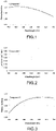
- FIG.1 and FIG.2 are respectively a graph showing a wavelength dispersion for the measured refractive index of the thin film of the compound 1 in the reference example 1; and a graph showing a wavelength dispersion for the measured extinction coefficient of the thin film of the compound 1 in the reference example 1.
- FIG.3 and FIG.4 are respectively a graph showing a wavelength dispersion for a measured refractive index of a thin film of the compound 2 in the reference example 2; and a graph showing a wavelength dispersion for a measured extinction coefficient of the thin film of the compound 2 in the reference example 2.
- FIG.5 and FIG.6 are respectively a graph showing a wavelength dispersion for a measured refractive index of a thin film of the compound 3 in the reference example 3; and a graph showing a wavelength dispersion for a measured extinction coefficient of the thin film of the compound 3 in the reference example 3.
- the optical constants were measured by a method similar to the one employed in the reference example 1, except that in order to adjust the film thickness, surface roughness and haze value, the film thickness, surface roughness and haze value of the coating film were adjusted by dry wiping the surface of the coating film with a tissue paper after the coating film had cured (100 times back and forth with the tissue paper being pressed against the surface of the coating film at a load of 500 g/cm 2 to 1,000 g/cm 2 ) (working example 1).
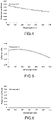
- FIG.7 and FIG.8 are respectively a graph showing a wavelength dispersion for a measured refractive index of an adjusted thin film of the compound 1 in the working example 1; and a graph showing a wavelength dispersion for a measured extinction coefficient of an adjusted thin film of the compound 1 in the working example 1.
- optical constants were measured by a method similar to the one employed in the reference example 2, except that in order to adjust the film thickness, surface roughness and haze value, the film thickness, surface roughness and haze value of the coating film were adjusted by dry wiping the surface of the coating film with a tissue paper after the coating film had cured (100 times back and forth with the tissue paper being pressed against the surface of the coating film at the load of 500 g/cm 2 to 1,000 g/cm 2 ) (working example 2).
- FIG.9 and FIG.10 are respectively a graph showing a wavelength dispersion for a measured refractive index of an adjusted thin film of the compound 2 in the working example 2; and a graph showing a wavelength dispersion for a measured extinction coefficient of an adjusted thin film of the compound 2 in the working example 2.
- the optical constants were measured by a method similar to the one employed in the reference example 3, except that in order to adjust the film thickness, surface roughness and haze value, the film thickness, surface roughness and haze value of the coating film were adjusted by dry wiping the surface of the coating film with a tissue paper after the coating film had cured (100 times back and forth with the tissue paper being pressed against the surface of the coating film at the load of 500 g/cm 2 to 1,000 g/cm 2 ) (working example 3).
- an Abbe's refractometer (DR-A1 by ATAGO CO., LTD.) was used to measure a refractive index of the compound 1 (bulk) at a wavelength of 589 nm under a temperature of 25°C.
- an Abbe's refractometer (DR-A1 by ATAGO CO., LTD.) was used to measure a refractive index of the compound 2 (bulk) at a wavelength of 589 nm under a temperature of 25°C.
- an Abbe's refractometer (DR-A1 by ATAGO CO., LTD.) was used to measure a refractive index of the compound 3 (bulk) at a wavelength of 589 nm under a temperature of 25°C.
Landscapes
- Chemical & Material Sciences (AREA)
- Physics & Mathematics (AREA)
- General Physics & Mathematics (AREA)
- Health & Medical Sciences (AREA)
- Life Sciences & Earth Sciences (AREA)
- General Health & Medical Sciences (AREA)
- Analytical Chemistry (AREA)
- Immunology (AREA)
- Biochemistry (AREA)
- Pathology (AREA)
- Chemical Kinetics & Catalysis (AREA)
- Organic Chemistry (AREA)
- Polymers & Plastics (AREA)
- Medicinal Chemistry (AREA)
- General Chemical & Material Sciences (AREA)
- Spectroscopy & Molecular Physics (AREA)
- Optics & Photonics (AREA)
- Mathematical Physics (AREA)
- Nuclear Medicine, Radiotherapy & Molecular Imaging (AREA)
- Radiology & Medical Imaging (AREA)
- Engineering & Computer Science (AREA)
- Wood Science & Technology (AREA)
- Materials Engineering (AREA)
- Investigating Or Analysing Materials By Optical Means (AREA)
- Length Measuring Devices By Optical Means (AREA)
- Surface Treatment Of Optical Elements (AREA)
- Polyethers (AREA)
Abstract
a step of forming the thin film of the fluorine-containing organosilicon compound on a base material, the thin film having, as surface roughnesses, an arithmetic mean roughness of smaller than 1.0 nm and a root mean square roughness of smaller than 2.0 nm, a haze value of smaller than 0.3 and a film thickness of 3 to 10 nm; and
a step of measuring the optical constants of the thin film formed on the base material by the ellipsometry method.
Description
- The present invention relates to a method for measuring optical constants of a thin film of a fluorine-containing organosilicon compound.
- The fluorine-containing organosilicon compound composing the thin film as a target of the optical constant measurement method of the present invention is a hydrolyzable fluorine-containing organosilicon compound usually having, in each molecule, a repetitive structure of perfluorooxyalkylene units (perfluoropolyether structure), and at least two hydrolyzable silyl groups or the like such as alkoxysilyl groups; and is disclosed in, for example,
Patent documents 1 to 4. These hydrolyzable fluorine-containing organosilicon compounds are used in a way such that they are applied to the surfaces of base materials such as metals, porcelain and glass to be cured so as to then form a water and oil repellent layer (antifouling coating thin film layer) on the surfaces of these base materials, thereby imparting to the base materials a function for avoiding oil and fat stains, fingerprint stains as well as other types of stains. In recent days, this type of compound is used for antifouling purpose on antireflective films of in-vehicle lenses, in-vehicle displays and displays for mobile electronic device terminals. - In general, optical constants (refractive index n, extinction coefficient κ) of an inorganic material (particularly, an optical material such as glass and other metal oxides) are measured using a bulk sample, where the optical constants are measured based on measured values of a spectral transmittance and spectral reflectivity of the bulk sample; and as for refractive index alone, a bulk sample molded and processed into a particular shape is used, and the measurement is carried out by, for example, a minimum deviation angle method, a critical angle method (with Abbe's refractometer) or a V-block method.
- Meanwhile, in the case of a bulk sample capable of forming a flat surface, an ellipsometry method is also used to measure optical constants. Further, if the sample is a thin film, the ellipsometry method can also be utilized to measure the film thickness of such thin film.
- However, it is known that the optical constants of a thin film sample are different from the optical constants of a bulk sample obtained from a material composing the thin film sample. While there are various reasons for that, one of them may, for the example, be the fact that a bulk sample differs from a thin film sample in density and porosity.
- For example, in the case of silicon dioxide (SiO2), a correlation between density and refractive index is particularly well known. According to
Non-patent document 1, the refractive index is significantly sensitive to the density. - Conventionally, optical constants of a hydrolyzable fluorine-containing organosilicon compound are measured using a solution prepared by dissolving the compound into a fluorine-based solvent, where the optical constants are then indirectly measured based on measured values of a spectral transmittance and spectral reflectivity of such solution. Further, as for the refractive index of a hydrolyzable fluorine-containing organosilicon compound alone, the measurement is conventionally performed on a liquid sample (bulk sample) by, for example, a minimum deviation angle method, a critical angle method (with Abbe's refractometer) or a V-block method.
- However, there has never been disclosed a method for directly measuring optical constants of a thin film formed of any of these hydrolyzable fluorine-containing organosilicon compounds.
-
- Patent document 1:
JP-A-2016-210854 - Patent document 2:
WO2017/212850 - Patent document 3:
Japanese Patent No.5761305 - Patent document 4:
Japanese Patent No.6451279 - Non-patent document 1: Phys. Chem. Minerals, 16, 286-290 (1988)
- Thus, the purpose of the present invention is to directly measure, by ellipsometry, optical constants (refractive index n, extinction coefficient κ) of a thin film sample of a fluorine-containing organosilicon compound, particularly a hydrolyzable fluorine-containing organosilicon compound, so that it will be possible to precisely and reproducibly measure the optical constants (refractive index n, extinction coefficient κ) of a fluorine-containing organosilicon compound thin film considered as exhibiting values of optical constants that are different from those of a bulk sample or a solution sample due to a difference in density and porosity.
- The inventor of the present invention diligently conducted a series of studies to achieve the above purpose, and completed the invention as follows. That is, the inventor found that by utilizing an ellipsometry method to perform a measurement on a fluorine-containing organosilicon compound thin film that is formed on a base material, and has a flat and homogeneous surface as well as a thickness of 3 to 10 nm, the optical constants of the fluorine-containing organosilicon compound thin film can be precisely, reproducibly and directly measured.
- That is, the present invention is to provide the following method for measuring optical constants of a thin film of a fluorine-containing organosilicon compound.
-
- [1] A method for measuring optical constants of a thin film of a fluorine-containing organosilicon compound, comprising:
- a step of forming the thin film of the fluorine-containing organosilicon compound on a base material, the thin film having, as surface roughnesses, an arithmetic mean roughness of smaller than 1.0 nm and a root mean square roughness of smaller than 2.0 nm, a haze value of smaller than 0.3 and a film thickness of 3 to 10 nm; and
- a step of measuring the optical constants of the thin film formed on the base material by an ellipsometry method.
- [2] The method for measuring the optical constants of the thin film of the fluorine-containing organosilicon compound according to [1], wherein the step of measuring the optical constants of the thin film formed on the base material by the ellipsometry method is a step where a value of a phase angle Δ of an elliptically polarized light with regard to the thin film and a value of a tangent ψ obtained from an amplitude intensity ratio of the elliptically polarized light are measured, followed by identifying the optical constants of the thin film based on the Δ value and ψ value measured.
- [3] The method for measuring the optical constants of the thin film of the fluorine-containing organosilicon compound according to [1] or [2], wherein the optical constants are a refractive index (n) and/or an extinction coefficient (κ).
- [4] The method for measuring the optical constants of the thin film of the fluorine-containing organosilicon compound according to any one of [1] to [3], wherein the base material is selected from a silicon single crystal base material, a glass base material, and a silicon single crystal base material coated with a silicon dioxide film.
- [5] The method for measuring the optical constants of the thin film of the fluorine-containing organosilicon compound according to any one of [1] to [4], wherein the film thickness of the thin film of the fluorine-containing organosilicon compound is measured by an atom force microscope or a stylus type step profiler.
- [6] The method for measuring the optical constants of the thin film of the fluorine-containing organosilicon compound according to any one of [1] to [5], wherein the surface roughnesses of the thin film of the fluorine-containing organosilicon compound are measured by a method in accordance with JIS B0601:2013.
- [7] The method for measuring the optical constants of the thin film of the fluorine-containing organosilicon compound according to any one of [1] to [6], wherein the haze value of the thin film of the fluorine-containing organosilicon compound is measured by a method in accordance with JIS K7136:2000.
- According to the present invention, the method of the invention is capable of directly and precisely measuring, by an ellipsometry method, optical constants of a fluorine-containing organosilicon compound thin film having a homogeneous surface with a small surface roughness and haze value, and is capable of reproducibly measuring optical constants (refractive index n, extinction coefficient κ) of a fluorine-containing organosilicon compound thin film originally considered as exhibiting values of optical constants that are different from those of a bulk sample or a solution sample owing to a difference in density and porosity.
-
-
FIG.1 is a graph showing a wavelength dispersion for a measured refractive index of a thin film of acompound 1 in a reference example 1. -
FIG.2 is a graph showing a wavelength dispersion for a measured extinction coefficient of the thin film of thecompound 1 in the reference example 1. -
FIG.3 is a graph showing a wavelength dispersion for a measured refractive index of a thin film of acompound 2 in a reference example 2. -
FIG.4 is a graph showing a wavelength dispersion for a measured extinction coefficient of the thin film of thecompound 2 in the reference example 2. -
FIG.5 is a graph showing a wavelength dispersion for a measured refractive index of a thin film of acompound 3 in a reference example 3. -
FIG.6 is a graph showing a wavelength dispersion for a measured extinction coefficient of the thin film of thecompound 3 in the reference example 3. -
FIG.7 is a graph showing a wavelength dispersion for a measured refractive index of an adjusted thin film of thecompound 1 in a working example 1. -
FIG.8 is a graph showing a wavelength dispersion for a measured extinction coefficient of the adjusted thin film of thecompound 1 in the working example 1. -
FIG.9 is a graph showing a wavelength dispersion for a measured refractive index of an adjusted thin film of thecompound 2 in a working example 2. -
FIG.10 is a graph showing a wavelength dispersion for a measured extinction coefficient of the adjusted thin film of thecompound 2 in the working example 2. -
FIG.1 1 is a graph showing a wavelength dispersion for a measured refractive index of an adjusted thin film of thecompound 3 in a working example 3. -
FIG.12 is a graph showing a wavelength dispersion for a measured extinction coefficient of the adjusted thin film of thecompound 3 in the working example 3. - The method of the present invention for measuring optical constants has a step of forming a thin film of a fluorine-containing organosilicon compound on a base material, the thin film having, as surface roughnesses, an arithmetic mean roughness of smaller than 1.0 nm and a root mean square roughness of smaller than 2.0 nm, a haze value of smaller than 0.3 and a film thickness of 3 to 10 nm; and a step of measuring optical constants of the thin film formed on the base material by an ellipsometry method.
- In the beginning, in the first step, the thin film of the fluorine-containing organosilicon compound is formed, and a homogeneity of the thin film of the fluorine-containing organosilicon compound is to be confirmed. Specifically, the homogeneity of the thin film of the fluorine-containing organosilicon compound is confirmed by measuring the surface roughness, film thickness and haze value.
- The thin film of the fluorine-containing organosilicon compound is obtained by applying a coating liquid to the surface of a flat base material by means of, for example, spray coating, ink-jet coating, spin coating, dip coating or vacuum deposition coating, the coating liquid containing a fluorine-containing organosilicon compound disclosed in, for example, any of the
Patent documents 1 to 4, particularly a hydrolyzable fluorine-containing organosilicon compound having, in each molecule, a repetitive structure of perfluorooxyalkylene units (perfluoropolyether structure), and at least two hydrolyzable silyl groups or the like such as alkoxysilyl groups. It is preferred that the arithmetic mean roughness of the surface of the base material be smaller than 1.0 nm, and that the root mean square roughness thereof be smaller than 2.0 nm; the material of the base material may be a silicon single crystal, a glass or a silicon single crystal surface-treated with SiO2, (base material with a SiO2 film previously formed thereon by, for example, deposition, sputtering, CVD or a thermal oxidation treatment). - A solvent used in the coating liquid may, for example, be a fluorine-modified aliphatic hydrocarbon-based solvent (e.g. perfluoroheptane, perfluorooctane); a fluorine-modified aromatic hydrocarbon-based solvent (e.g. 1,3-bis(trifluoromethyl)benzene); a fluorine-modified ether-based solvent (e.g. methylperfluorobutylether, ethylperfluorobutylether, perfluoro(2-butyltetrahydrofuran)); a fluorine-modified alkylamine-based solvent (e.g. perfluorotributylamine, perfluorotripentylamine); a hydrocarbon-based solvent (e.g. petroleum benzine, toluene, xylene); or a ketone-based solvent (e.g. acetone, methylethylketone, methylisobutylketone). Among these solvents, a fluorine-modified solvent is desired in terms of solubility and wettability; particularly preferred are 1,3-bis(trifluoromethyl)benzene, perfluoro(2-butyltetrahydrofuran), perfluorotributylamine and ethylperfluorobutylether.
- Any two or more kinds of these solvents may be mixed together, and it is preferred that the hydrolyzable fluorine-containing organosilicon compound be uniformly dissolved therein. Here, an optimum concentration of the hydrolyzable fluorine-containing organosilicon compound to be dissolved in the solvent varies depending on a treating method; the compound may simply be in an easily weighable amount. If employing spray coating, ink-jet coating, spin coating or dip coating, it is preferred that the hydrolyzable fluorine-containing organosilicon compound be in an amount of 0.01 to 10 parts by mass, particularly preferably 0.05 to 5 parts by mass, per 100 parts by mass of a sum total of the solvent and the hydrolyzable fluorine-containing organosilicon compound; if employing vacuum deposition coating, it is preferred that the hydrolyzable fluorine-containing organosilicon compound be in an amount of 1 to 100 parts by mass, particularly preferably 3 to 30 parts by mass, per 100 parts by mass of the sum total of the solvent and the hydrolyzable fluorine-containing organosilicon compound.
- When left under an environmental atmosphere for a given period of time, the fluorine-containing organosilicon compound applied to (formed as a film on) the surface of the base material will favorably adhere to the base material as a result of being cured by hydrolytic condensation owing to the moisture (water) in the atmosphere. As a condition(s) for leaving the fluorine-containing organosilicon compound and the base material, they may, for example, be left under an atmosphere having a temperature of 25°C and a relative humidity of 50% for 12 hours, or at 150°C for an hour.
- Using an atom force microscope or a stylus type step profiler, and by establishing a thin film-uncoated portion via a masking treatment or the like, the film thickness of the thin film of the fluorine-containing organosilicon compound can be measured based on a difference in height between the thin film-uncoated portion and a thin film-coated portion.
- Further, the film thickness of the thin film of the fluorine-containing organosilicon compound can also be measured by fluorescent X-ray measurement. In such case, it is necessary to draw, in advance, a calibration curve showing a correlation between the film thickness obtained using the atom force microscope or stylus type step profiler and a fluorescent X-ray intensity derived from elemental fluorine.
- With a method according to JIS B0601:2013, the surface roughness is measured by measuring the arithmetic mean roughness and root mean square roughness of the surface of the thin film of the fluorine-containing organosilicon compound, using an atom force microscope or an optical three-dimensional shape measurement device (e.g. confocal laser microscope and laser interferometer).
- With a method according to JIS K7136:2000, the haze value is measured by measuring a haze value of the base material on which the thin film of the fluorine-containing organosilicon compound has been formed (applied thereto and cured thereon), using a hazemeter.
- As a result of measuring the film thickness, surface roughness and haze value of the thin film by the aforementioned methods, if each value is within the range(s) shown below, it is then regarded that a homogeneity of the thin film has been confirmed, followed by carrying out a step of measuring optical constants of the thin film by an ellipsometry method.
- The film thickness of the thin film of the fluorine-containing organosilicon compound is 3 to 10 nm, preferably 4 to 9 nm, more preferably 5 to 8 nm. If the thin film is thicker than 10 nm, a portion beyond 10 nm in thickness (an excess portion) will be removed by the following procedure.
- The excess portion of the thin film of the fluorine-containing organosilicon compound can be removed by either wiping it off with a commercially available tissue paper, or pouring and running a fluorine solvent thereon. After the removal of the excess portion, the film thickness is then confirmed by the above film thickness measurement method, and the removal process is to be repeated until an appropriate film thickness has been achieved.
- As for the surface roughness of the thin film of the fluorine-containing organosilicon compound, it is preferred that the arithmetic mean roughness is smaller than 1.0 nm (not smaller than 0 nm, but smaller than 1.0 nm), and the root mean square roughness is smaller than 2.0 nm (not smaller than 0 nm, but smaller than 2.0 nm); more preferably the arithmetic mean roughness is smaller than 0.5 nm (not smaller than 0 nm, but smaller than 0.5 nm), and the root mean square roughness is smaller than 1.0 nm (not smaller than 0 nm, but smaller than 1.0 nm); even more preferably the arithmetic mean roughness is 0 to 0.35 nm, and the root mean square roughness is 0 to 0.5 nm.
- It is preferred that the haze value of the thin film of the fluorine-containing organosilicon compound be smaller than 0.3 (not smaller than 0, but smaller than 0.3), more preferably not larger than 0.25 (0 to 0.25).
- When the surface roughness and haze value of the thin film of the fluorine-containing organosilicon compound are out of the preferable ranges in the present invention, the surface roughness and haze value are to be adjusted by a method identical to the method for adjusting the film thickness.
- An ellipsometry method is to allow a polarized light to enter a sample with a flat surface, and then measure changes in a polarization state of a reflected light, thereby making it possible to measure optical constants (refractive index n, extinction coefficient κ) of the sample as well as the film thickness thereof if the sample is a thin film.
- In the ellipsometry method employed in the method for measuring the optical constants of the thin film of the fluorine-containing organosilicon compound of the present invention, a linear polarized light is allowed to enter the thin film formed on the base material, followed by measuring a value of a phase angle Δ of an elliptically polarized light reflected and a value of a tangent ψ obtained from an amplitude intensity ratio of the elliptically polarized light. Here, if the film thickness of the thin film as well as the optical constants and thickness of the base material are known, the optical constants of the thin film (refractive index n, extinction coefficient κ) can be identified based on a correlation between these known values and the values of Δ and ψ measured. This measurement is carried out by an ellipsometer.
- The present invention is described in detail hereunder with reference to working and comparative examples; the present invention shall not be limited to the following working examples.
- A
compound 1 represented by the following formula was dissolved into a fluorine solvent (NOVEC7200 by 3M Company) so that a weight concentration would be 20%, thus obtaining a coating liquid.
- A glass base material on which a SiO2 film having a thickness of 10 nm had been formed was placed into a resistance heating-type vacuum deposition device (VTR-350M by ULVAC KIKO, Inc.), followed by delivering 4 µL of the coating liquid by drops onto a resistance heating part, and reducing the pressure. Resistance heating was started once the pressure inside the container was reduced to 3×10⁻³ Pa or lower. An electric power consumed for resistance heating was adjusted so that a maximum evaporation rate at a quartz crystal film thickness meter installed in a location about 20 cm away from the resistance heating part would be 1.0 nm/sec. After the evaporation rate at the quartz crystal film thickness meter had decreased to 0.1 nm/sec, resistance heating was continued for 100 sec. In order to cool the device, the device was left to stand for 5 min, followed by opening the device to the atmosphere so as to obtain a base material having a coating film of the
compound 1. - The base material having the coating film of the
compound 1 was left under an environment of 25°C, relative humidity 50% for not less than 12 hours, whereby the coating film was cured, and the thin film of thecompound 1 was thus obtained. - An atom force microscope (Nanocute by Hitachi High-Tech Corporation) was used to measure a surface topography image of a 500 nm squared region, thereby obtaining the film thickness of the thin film of the
compound 1. - A three-dimensional shape measurement microscope (LEXT OLS4100 by Olympus Corporation) was used to observe the surface shape of the thin film of the
compound 1 with the aid of an objective lens at 50-fold magnification, thereby obtaining the surface roughness of thecompound 1. If any of the arithmetic mean roughness or root mean square roughness was not larger than 2.0 nm, the surface roughness was then obtained from a surface topography image of an atom force microscope. - A hazemeter (NDH5000 by NIPPON DENSHOKU INDUSTRIES CO., LTD.) was used to measure the haze value of the thin film of the
compound 1. - An ellipsometer (M-2000D by J.A.Woollam Co., Inc.) was used to measure a phase angle Δ and a tangent ψ at an incidence angle of 57° to 59°. The data measured were then fitted into curves to obtain a wavelength dispersion for each optical constant. As for the film thickness, the value obtained by the above method was used.
FIG.1 and FIG.2 are respectively a graph showing a wavelength dispersion for the measured refractive index of the thin film of thecompound 1 in the reference example 1; and a graph showing a wavelength dispersion for the measured extinction coefficient of the thin film of thecompound 1 in the reference example 1. - The optical constants were measured by a method similar to the one employed in the reference example 1, except that the
compound 1 was substituted with acompound 2 represented by the following formula.FIG.3 andFIG.4 are respectively a graph showing a wavelength dispersion for a measured refractive index of a thin film of thecompound 2 in the reference example 2; and a graph showing a wavelength dispersion for a measured extinction coefficient of the thin film of thecompound 2 in the reference example 2.
- The optical constants were measured by a method similar to the one employed in the reference example 1, except that the
compound 1 was substituted with acompound 3.FIG.5 and FIG.6 are respectively a graph showing a wavelength dispersion for a measured refractive index of a thin film of thecompound 3 in the reference example 3; and a graph showing a wavelength dispersion for a measured extinction coefficient of the thin film of thecompound 3 in the reference example 3.

- The optical constants were measured by a method similar to the one employed in the reference example 1, except that in order to adjust the film thickness, surface roughness and haze value, the film thickness, surface roughness and haze value of the coating film were adjusted by dry wiping the surface of the coating film with a tissue paper after the coating film had cured (100 times back and forth with the tissue paper being pressed against the surface of the coating film at a load of 500 g/cm2 to 1,000 g/cm2) (working example 1).
FIG.7 and FIG.8 are respectively a graph showing a wavelength dispersion for a measured refractive index of an adjusted thin film of thecompound 1 in the working example 1; and a graph showing a wavelength dispersion for a measured extinction coefficient of an adjusted thin film of thecompound 1 in the working example 1. - The optical constants were measured by a method similar to the one employed in the reference example 2, except that in order to adjust the film thickness, surface roughness and haze value, the film thickness, surface roughness and haze value of the coating film were adjusted by dry wiping the surface of the coating film with a tissue paper after the coating film had cured (100 times back and forth with the tissue paper being pressed against the surface of the coating film at the load of 500 g/cm2 to 1,000 g/cm2) (working example 2).
FIG.9 andFIG.10 are respectively a graph showing a wavelength dispersion for a measured refractive index of an adjusted thin film of thecompound 2 in the working example 2; and a graph showing a wavelength dispersion for a measured extinction coefficient of an adjusted thin film of thecompound 2 in the working example 2. - The optical constants were measured by a method similar to the one employed in the reference example 3, except that in order to adjust the film thickness, surface roughness and haze value, the film thickness, surface roughness and haze value of the coating film were adjusted by dry wiping the surface of the coating film with a tissue paper after the coating film had cured (100 times back and forth with the tissue paper being pressed against the surface of the coating film at the load of 500 g/cm2 to 1,000 g/cm2) (working example 3).
FIG.11 and FIG. 12 are respectively a graph showing a wavelength dispersion for a measured refractive index of an adjusted thin film of thecompound 3 in the working example 3; and a graph showing a wavelength dispersion for a measured extinction coefficient of an adjusted thin film of thecompound 3 in the working example 3. - With regard to the
compound 1 in a liquid state, an Abbe's refractometer (DR-A1 by ATAGO CO., LTD.) was used to measure a refractive index of the compound 1 (bulk) at a wavelength of 589 nm under a temperature of 25°C. - With regard to the
compound 2 in a liquid state, an Abbe's refractometer (DR-A1 by ATAGO CO., LTD.) was used to measure a refractive index of the compound 2 (bulk) at a wavelength of 589 nm under a temperature of 25°C. - With regard to the
compound 3 in a liquid state, an Abbe's refractometer (DR-A1 by ATAGO CO., LTD.) was used to measure a refractive index of the compound 3 (bulk) at a wavelength of 589 nm under a temperature of 25°C. - The above measurement results are shown in Table 1. As can be seen from the results shown in Table 1, it was confirmed that the optical constants of the thin film sample of the fluorine-containing organosilicon compound were able to be directly, precisely and reproducibly measured by the method of the present invention for measuring optical constants. Further, it was confirmed that while the refractive indexes of the (adjusted) thin film samples of the
compounds 1 to 3 in the working examples 1 to 3, which were measured by the optical constant measurement method of the present invention, were well correlated with the refractive indexes of the (liquid) bulk samples of thecompounds 1 to 3, the measured values of the refractive indexes of the thin film samples were slightly different from the measured values of the refractive indexes of the bulk samples.[Table 1] Film thickness (nm) Arithmetic mean roughness (nm) Root mean square roughness (nm) Haze value Refractive ndex Reference example 1 11.3 3.0 3.0 1.23 1.195 Reference example 2 10.7 3.0 6.0 1.55 1.264 Reference example 3 10.5 11.0 22.0 3.01 1.164 Working example 1 5.2 0.23 0.30 0.25 1.288 Working example 2 5.4 0.25 0.31 0.24 1.295 Working example 3 5.5 0.25 0.30 0.24 1.292 Comparative example 1 - - - - 1.308 Comparative example 2 - - - - 1.311 Comparative example 3 - - - - 1.312
Claims (7)
- A method for measuring optical constants of a thin film of a fluorine-containing organosilicon compound, comprising:a step of forming the thin film of the fluorine-containing organosilicon compound on a base material, the thin film having, as surface roughnesses, an arithmetic mean roughness of smaller than 1.0 nm and a root mean square roughness of smaller than 2.0 nm, a haze value of smaller than 0.3 and a film thickness of 3 to 10 nm; anda step of measuring the optical constants of the thin film formed on the base material by an ellipsometry method.
- The method for measuring the optical constants of the thin film of the fluorine-containing organosilicon compound according to claim 1, wherein the step of measuring the optical constants of the thin film formed on the base material by the ellipsometry method is a step where a value of a phase angle Δ of an elliptically polarized light with regard to the thin film and a value of a tangent ψ obtained from an amplitude intensity ratio of the elliptically polarized light are measured, followed by identifying the optical constants of the thin film based on the Δ value and ψ value measured.
- The method for measuring the optical constants of the thin film of the fluorine-containing organosilicon compound according to claim 1 or 2, wherein the optical constants are a refractive index (n) and/or an extinction coefficient (κ).
- The method for measuring the optical constants of the thin film of the fluorine-containing organosilicon compound according to any one of claims 1 to 3, wherein the base material is selected from a silicon single crystal base material, a glass base material, and a silicon single crystal base material coated with a silicon dioxide film.
- The method for measuring the optical constants of the thin film of the fluorine-containing organosilicon compound according to any one of claims 1 to 4, wherein the film thickness of the thin film of the fluorine-containing organosilicon compound is measured by an atom force microscope or a stylus type step profiler.
- The method for measuring the optical constants of the thin film of the fluorine-containing organosilicon compound according to any one of claims 1 to 5, wherein the surface roughnesses of the thin film of the fluorine-containing organosilicon compound are measured by a method in accordance with JIS B0601:2013.
- The method for measuring the optical constants of the thin film of the fluorine-containing organosilicon compound according to any one of claims 1 to 6, wherein the haze value of the thin film of the fluorine-containing organosilicon compound is measured by a method in accordance with JIS K7136:2000.
Applications Claiming Priority (2)
| Application Number | Priority Date | Filing Date | Title |
|---|---|---|---|
| JP2019145856 | 2019-08-08 | ||
| PCT/JP2020/029192 WO2021024895A1 (en) | 2019-08-08 | 2020-07-30 | Method for measuring optical constant of fluorine-containing organosilicon compound thin film |
Publications (3)
| Publication Number | Publication Date |
|---|---|
| EP4011935A1 true EP4011935A1 (en) | 2022-06-15 |
| EP4011935A4 EP4011935A4 (en) | 2023-05-10 |
| EP4011935B1 EP4011935B1 (en) | 2025-10-15 |
Family
ID=74503599
Family Applications (1)
| Application Number | Title | Priority Date | Filing Date |
|---|---|---|---|
| EP20850692.3A Active EP4011935B1 (en) | 2019-08-08 | 2020-07-30 | Method for measuring optical constants of thin film of fluorine-containing organosilicon compound |
Country Status (6)
| Country | Link |
|---|---|
| US (1) | US12105018B2 (en) |
| EP (1) | EP4011935B1 (en) |
| JP (1) | JP7188600B2 (en) |
| KR (1) | KR102830903B1 (en) |
| CN (2) | CN120971345A (en) |
| WO (1) | WO2021024895A1 (en) |
Families Citing this family (1)
| Publication number | Priority date | Publication date | Assignee | Title |
|---|---|---|---|---|
| EP4382290A4 (en) * | 2021-08-05 | 2025-07-30 | Shinetsu Chemical Co | ARTICLES WITH WATER AND OIL-REPELLENT SURFACE LAYER |
Family Cites Families (26)
| Publication number | Priority date | Publication date | Assignee | Title |
|---|---|---|---|---|
| US4097370A (en) | 1977-04-14 | 1978-06-27 | The Lummus Company | Hydrotreating of pyrolysis gasoline |
| JPS57200192A (en) | 1981-06-03 | 1982-12-08 | Matsushita Electric Industrial Co Ltd | Washing machine with washstand |
| JP2561395B2 (en) * | 1991-02-27 | 1996-12-04 | ホーヤ株式会社 | Optical member having water-repellent thin film and method for manufacturing the same |
| JP3283407B2 (en) * | 1995-09-13 | 2002-05-20 | ジーイー東芝シリコーン株式会社 | Polysilane optical device |
| JP3644863B2 (en) * | 2000-01-24 | 2005-05-11 | 沖電気工業株式会社 | Film thickness distribution measurement method |
| CN101151711A (en) * | 2005-03-31 | 2008-03-26 | 松下电器产业株式会社 | Plasma doping method and apparatus |
| WO2006134218A1 (en) * | 2005-06-15 | 2006-12-21 | Braggone Oy | Optical device structure |
| JP2007062101A (en) * | 2005-08-30 | 2007-03-15 | Nippon Zeon Co Ltd | Antireflection laminate |
| JP5239219B2 (en) | 2007-06-12 | 2013-07-17 | 株式会社豊田中央研究所 | Optical element manufacturing method |
| JP2010237623A (en) * | 2009-03-31 | 2010-10-21 | Fujifilm Corp | Antireflection film, polarizing plate, image display device |
| JP5781350B2 (en) * | 2011-03-30 | 2015-09-24 | リンテック株式会社 | GAS BARRIER LAMINATE, ITS MANUFACTURING METHOD, ELECTRONIC DEVICE MEMBER AND ELECTRONIC DEVICE |
| JP2013174668A (en) | 2012-02-23 | 2013-09-05 | Asahi Glass Co Ltd | Production apparatus and production method for fluorine-containing organic silicon compound thin film |
| KR20140130437A (en) | 2012-02-23 | 2014-11-10 | 아사히 가라스 가부시키가이샤 | Device and method for producing fluorine-containing organosilicon compound thin film |
| AU2013339455A1 (en) | 2012-11-05 | 2015-05-21 | Nikon-Essilor Co., Ltd. | Optical component, method for producing optical component, and method for quantitatively determining ghost light |
| CN104769009B (en) | 2012-11-05 | 2017-08-11 | 大金工业株式会社 | Containing perfluor (poly-) ether silane compound |
| JP6451279B2 (en) | 2014-03-31 | 2019-01-16 | 信越化学工業株式会社 | Fluoropolyether group-containing polymer-modified silane, surface treatment agent and article |
| CN107107543B (en) | 2014-10-30 | 2021-07-20 | Agc株式会社 | Substrate with antifouling film |
| JP6260579B2 (en) | 2015-05-01 | 2018-01-17 | 信越化学工業株式会社 | Fluoropolyether group-containing polymer-modified silane, surface treatment agent and article |
| JP6772564B2 (en) | 2016-06-06 | 2020-10-21 | 大日本印刷株式会社 | Water contact angle control method of optical laminate, and optical laminate with protective film |
| JP6828744B2 (en) | 2016-06-10 | 2021-02-10 | 信越化学工業株式会社 | Fluoropolyester group-containing polymers, surface treatment agents and articles |
| CN113835143B (en) * | 2016-10-07 | 2023-12-05 | Agc株式会社 | Substrate with anti-glare film, liquid composition for forming anti-glare film, and method for manufacturing the substrate with anti-glare film |
| JP6780619B2 (en) | 2016-11-11 | 2020-11-04 | Agc株式会社 | Substrate with low reflective film and its manufacturing method |
| US10877181B2 (en) * | 2016-11-11 | 2020-12-29 | AGC Inc. | Substrate with low-reflection property and manufacturing method thereof |
| WO2019073946A1 (en) | 2017-10-10 | 2019-04-18 | Agc株式会社 | COATING ELEMENT |
| CN109722082A (en) * | 2017-10-31 | 2019-05-07 | 株式会社E-Tec | Coating composition |
| CN109141259B (en) * | 2018-08-06 | 2020-06-30 | 华中科技大学 | Device and method for measuring optical constant and thickness of thin absorbing film |
-
2020
- 2020-07-30 KR KR1020227007193A patent/KR102830903B1/en active Active
- 2020-07-30 JP JP2021537261A patent/JP7188600B2/en active Active
- 2020-07-30 US US17/632,035 patent/US12105018B2/en active Active
- 2020-07-30 WO PCT/JP2020/029192 patent/WO2021024895A1/en not_active Ceased
- 2020-07-30 CN CN202511492327.XA patent/CN120971345A/en active Pending
- 2020-07-30 CN CN202080054734.1A patent/CN114174803A/en active Pending
- 2020-07-30 EP EP20850692.3A patent/EP4011935B1/en active Active
Also Published As
| Publication number | Publication date |
|---|---|
| EP4011935A4 (en) | 2023-05-10 |
| EP4011935B1 (en) | 2025-10-15 |
| JP7188600B2 (en) | 2022-12-13 |
| CN114174803A (en) | 2022-03-11 |
| US12105018B2 (en) | 2024-10-01 |
| JPWO2021024895A1 (en) | 2021-02-11 |
| KR20220044773A (en) | 2022-04-11 |
| KR102830903B1 (en) | 2025-07-08 |
| US20220276151A1 (en) | 2022-09-01 |
| WO2021024895A1 (en) | 2021-02-11 |
| CN120971345A (en) | 2025-11-18 |
Similar Documents
| Publication | Publication Date | Title |
|---|---|---|
| EP1000124B1 (en) | Antisoiling coatings for antireflective surfaces and methods of preparation | |
| CN107777894B (en) | Optical coating method, apparatus and product | |
| DE69405613T2 (en) | Abrasion-resistant coating compositions based on hydrolyzed silanes and aluminum compounds; abrasion-resistant and impact-resistant objects | |
| EP2403817A1 (en) | Slot die coating process | |
| Namoune et al. | Thickness, annealing and substrate effects on structural, morphological, optical and waveguiding properties of RF sputtered ZnO thin films | |
| Mertin et al. | Nanocrystalline Low‐Refractive Magnesium Fluoride Films Deposited by Reactive Magnetron Sputtering: Optical and Structural Properties | |
| KR20210090670A (en) | Easy-to-clean coating | |
| EP4011935B1 (en) | Method for measuring optical constants of thin film of fluorine-containing organosilicon compound | |
| US20190169445A1 (en) | Surface-treating agent and article comprising layer formed from surface-treating agent | |
| EP2602293B1 (en) | Coating structure and method for forming the same | |
| EP3063235B1 (en) | Article having coating on substrate, coating composition, and coating method | |
| EP3978232A1 (en) | Transparent substrate with antifouling layer | |
| Brenier et al. | Stress development in amorphous zirconium oxide films prepared by sol-gel processing | |
| Steenhusen et al. | Increased durability of sol–gel derived MgF2 antireflective coatings capped by vapor deposition | |
| JP2008256373A (en) | Method of evaluating vapor deposition film, and method of manufacturing optical member using the same | |
| Landwehr et al. | Optical polymers with tunable refractive index for nanoimprint technologies | |
| US20220306892A1 (en) | Water- and oil-repelling member and water- and oil-repelling member production method | |
| Kourtakis et al. | Novel thermal and photo curable anti-reflective coatings using fluoroelastomer nanocomposites and self-assembly of nanoparticles | |
| JP7259789B2 (en) | Quality evaluation method and quality control method for thin film of hydrolyzable fluorine-containing organosilicon compound | |
| US10099247B2 (en) | Anti-reflective coating for sapphire | |
| Katayama et al. | Characterization of SiO2 films on glass substrate by sol-gel and vacuum deposition methods | |
| Vretenar | Mechanical stresses in oxide thin films | |
| Sitarz et al. | Optical and mechanical characterization of zirconium based sol-gel coatings on glass | |
| O'Brien et al. | Reliability Analysis of an Inorganic-Organic Hybrid Sol-gel Material System for Waveguiding Applications | |
| Blinov et al. | Electro-Optic Effect in Thin Films of a Dielectric and a Ferroelectric with Subwavelength Aluminum Grating |
Legal Events
| Date | Code | Title | Description |
|---|---|---|---|
| STAA | Information on the status of an ep patent application or granted ep patent |
Free format text: STATUS: THE INTERNATIONAL PUBLICATION HAS BEEN MADE |
|
| PUAI | Public reference made under article 153(3) epc to a published international application that has entered the european phase |
Free format text: ORIGINAL CODE: 0009012 |
|
| STAA | Information on the status of an ep patent application or granted ep patent |
Free format text: STATUS: REQUEST FOR EXAMINATION WAS MADE |
|
| 17P | Request for examination filed |
Effective date: 20220222 |
|
| AK | Designated contracting states |
Kind code of ref document: A1 Designated state(s): AL AT BE BG CH CY CZ DE DK EE ES FI FR GB GR HR HU IE IS IT LI LT LU LV MC MK MT NL NO PL PT RO RS SE SI SK SM TR |
|
| A4 | Supplementary search report drawn up and despatched |
Effective date: 20230412 |
|
| RIC1 | Information provided on ipc code assigned before grant |
Ipc: G02B 1/111 20150101ALI20230404BHEP Ipc: G01N 21/84 20060101ALI20230404BHEP Ipc: G01N 21/21 20060101ALI20230404BHEP Ipc: C09D 171/00 20060101ALI20230404BHEP Ipc: C08G 65/00 20060101ALI20230404BHEP Ipc: G02B 1/18 20150101ALI20230404BHEP Ipc: G01N 21/49 20060101ALI20230404BHEP Ipc: G01N 21/41 20060101ALI20230404BHEP Ipc: G01J 4/04 20060101ALI20230404BHEP Ipc: C08G 65/336 20060101AFI20230404BHEP |
|
| STAA | Information on the status of an ep patent application or granted ep patent |
Free format text: STATUS: EXAMINATION IS IN PROGRESS |
|
| 17Q | First examination report despatched |
Effective date: 20231107 |
|
| GRAP | Despatch of communication of intention to grant a patent |
Free format text: ORIGINAL CODE: EPIDOSNIGR1 |
|
| STAA | Information on the status of an ep patent application or granted ep patent |
Free format text: STATUS: GRANT OF PATENT IS INTENDED |
|
| INTG | Intention to grant announced |
Effective date: 20250519 |
|
| RIN1 | Information on inventor provided before grant (corrected) |
Inventor name: UCHIDA, TAKASHI |
|
| GRAS | Grant fee paid |
Free format text: ORIGINAL CODE: EPIDOSNIGR3 |
|
| GRAA | (expected) grant |
Free format text: ORIGINAL CODE: 0009210 |
|
| STAA | Information on the status of an ep patent application or granted ep patent |
Free format text: STATUS: THE PATENT HAS BEEN GRANTED |
|
| AK | Designated contracting states |
Kind code of ref document: B1 Designated state(s): AL AT BE BG CH CY CZ DE DK EE ES FI FR GB GR HR HU IE IS IT LI LT LU LV MC MK MT NL NO PL PT RO RS SE SI SK SM TR |
|
| REG | Reference to a national code |
Ref country code: GB Ref legal event code: FG4D Ref country code: CH Ref legal event code: F10 Free format text: ST27 STATUS EVENT CODE: U-0-0-F10-F00 (AS PROVIDED BY THE NATIONAL OFFICE) Effective date: 20251015 |
|
| REG | Reference to a national code |
Ref country code: IE Ref legal event code: FG4D |
|
| REG | Reference to a national code |
Ref country code: DE Ref legal event code: R096 Ref document number: 602020060641 Country of ref document: DE |
|
| P01 | Opt-out of the competence of the unified patent court (upc) registered |
Free format text: CASE NUMBER: UPC_APP_9208_4011935/2025 Effective date: 20251007 |
|
| REG | Reference to a national code |
Ref country code: NL Ref legal event code: MP Effective date: 20251015 |
|
| REG | Reference to a national code |
Ref country code: AT Ref legal event code: MK05 Ref document number: 1846922 Country of ref document: AT Kind code of ref document: T Effective date: 20251015 |
|
| PG25 | Lapsed in a contracting state [announced via postgrant information from national office to epo] |
Ref country code: NL Free format text: LAPSE BECAUSE OF FAILURE TO SUBMIT A TRANSLATION OF THE DESCRIPTION OR TO PAY THE FEE WITHIN THE PRESCRIBED TIME-LIMIT Effective date: 20251015 |
|
| PG25 | Lapsed in a contracting state [announced via postgrant information from national office to epo] |
Ref country code: ES Free format text: LAPSE BECAUSE OF FAILURE TO SUBMIT A TRANSLATION OF THE DESCRIPTION OR TO PAY THE FEE WITHIN THE PRESCRIBED TIME-LIMIT Effective date: 20251015 |
|
| REG | Reference to a national code |
Ref country code: LT Ref legal event code: MG9D |
|
| PG25 | Lapsed in a contracting state [announced via postgrant information from national office to epo] |
Ref country code: NO Free format text: LAPSE BECAUSE OF FAILURE TO SUBMIT A TRANSLATION OF THE DESCRIPTION OR TO PAY THE FEE WITHIN THE PRESCRIBED TIME-LIMIT Effective date: 20260115 |
|
| PG25 | Lapsed in a contracting state [announced via postgrant information from national office to epo] |
Ref country code: AT Free format text: LAPSE BECAUSE OF FAILURE TO SUBMIT A TRANSLATION OF THE DESCRIPTION OR TO PAY THE FEE WITHIN THE PRESCRIBED TIME-LIMIT Effective date: 20251015 Ref country code: HR Free format text: LAPSE BECAUSE OF FAILURE TO SUBMIT A TRANSLATION OF THE DESCRIPTION OR TO PAY THE FEE WITHIN THE PRESCRIBED TIME-LIMIT Effective date: 20251015 Ref country code: FI Free format text: LAPSE BECAUSE OF FAILURE TO SUBMIT A TRANSLATION OF THE DESCRIPTION OR TO PAY THE FEE WITHIN THE PRESCRIBED TIME-LIMIT Effective date: 20251015 |
|
| PG25 | Lapsed in a contracting state [announced via postgrant information from national office to epo] |
Ref country code: RS Free format text: LAPSE BECAUSE OF FAILURE TO SUBMIT A TRANSLATION OF THE DESCRIPTION OR TO PAY THE FEE WITHIN THE PRESCRIBED TIME-LIMIT Effective date: 20260115 |
|
| PG25 | Lapsed in a contracting state [announced via postgrant information from national office to epo] |
Ref country code: IS Free format text: LAPSE BECAUSE OF FAILURE TO SUBMIT A TRANSLATION OF THE DESCRIPTION OR TO PAY THE FEE WITHIN THE PRESCRIBED TIME-LIMIT Effective date: 20260215 |
|
| PG25 | Lapsed in a contracting state [announced via postgrant information from national office to epo] |
Ref country code: PT Free format text: LAPSE BECAUSE OF FAILURE TO SUBMIT A TRANSLATION OF THE DESCRIPTION OR TO PAY THE FEE WITHIN THE PRESCRIBED TIME-LIMIT Effective date: 20260216 |
|
| PG25 | Lapsed in a contracting state [announced via postgrant information from national office to epo] |
Ref country code: PL Free format text: LAPSE BECAUSE OF FAILURE TO SUBMIT A TRANSLATION OF THE DESCRIPTION OR TO PAY THE FEE WITHIN THE PRESCRIBED TIME-LIMIT Effective date: 20251015 |
|
| PG25 | Lapsed in a contracting state [announced via postgrant information from national office to epo] |
Ref country code: LV Free format text: LAPSE BECAUSE OF FAILURE TO SUBMIT A TRANSLATION OF THE DESCRIPTION OR TO PAY THE FEE WITHIN THE PRESCRIBED TIME-LIMIT Effective date: 20251015 |
|
| PG25 | Lapsed in a contracting state [announced via postgrant information from national office to epo] |
Ref country code: BG Free format text: LAPSE BECAUSE OF FAILURE TO SUBMIT A TRANSLATION OF THE DESCRIPTION OR TO PAY THE FEE WITHIN THE PRESCRIBED TIME-LIMIT Effective date: 20251015 |