EP4011778A1 - Recirculation ground maintenance mode - Google Patents
Recirculation ground maintenance mode Download PDFInfo
- Publication number
- EP4011778A1 EP4011778A1 EP21212619.7A EP21212619A EP4011778A1 EP 4011778 A1 EP4011778 A1 EP 4011778A1 EP 21212619 A EP21212619 A EP 21212619A EP 4011778 A1 EP4011778 A1 EP 4011778A1
- Authority
- EP
- European Patent Office
- Prior art keywords
- cabin
- recirculation
- air
- cooling zone
- power
- Prior art date
- Legal status (The legal status is an assumption and is not a legal conclusion. Google has not performed a legal analysis and makes no representation as to the accuracy of the status listed.)
- Granted
Links
Images



Classifications
-
- B—PERFORMING OPERATIONS; TRANSPORTING
- B64—AIRCRAFT; AVIATION; COSMONAUTICS
- B64D—EQUIPMENT FOR FITTING IN OR TO AIRCRAFT; FLIGHT SUITS; PARACHUTES; ARRANGEMENT OR MOUNTING OF POWER PLANTS OR PROPULSION TRANSMISSIONS IN AIRCRAFT
- B64D13/00—Arrangements or adaptations of air-treatment apparatus for aircraft crew or passengers, or freight space
- B64D13/06—Arrangements or adaptations of air-treatment apparatus for aircraft crew or passengers, or freight space the air being conditioned
-
- B—PERFORMING OPERATIONS; TRANSPORTING
- B64—AIRCRAFT; AVIATION; COSMONAUTICS
- B64D—EQUIPMENT FOR FITTING IN OR TO AIRCRAFT; FLIGHT SUITS; PARACHUTES; ARRANGEMENT OR MOUNTING OF POWER PLANTS OR PROPULSION TRANSMISSIONS IN AIRCRAFT
- B64D13/00—Arrangements or adaptations of air-treatment apparatus for aircraft crew or passengers, or freight space
- B64D13/02—Arrangements or adaptations of air-treatment apparatus for aircraft crew or passengers, or freight space the air being pressurised
-
- B—PERFORMING OPERATIONS; TRANSPORTING
- B64—AIRCRAFT; AVIATION; COSMONAUTICS
- B64D—EQUIPMENT FOR FITTING IN OR TO AIRCRAFT; FLIGHT SUITS; PARACHUTES; ARRANGEMENT OR MOUNTING OF POWER PLANTS OR PROPULSION TRANSMISSIONS IN AIRCRAFT
- B64D13/00—Arrangements or adaptations of air-treatment apparatus for aircraft crew or passengers, or freight space
- B64D13/06—Arrangements or adaptations of air-treatment apparatus for aircraft crew or passengers, or freight space the air being conditioned
- B64D13/08—Arrangements or adaptations of air-treatment apparatus for aircraft crew or passengers, or freight space the air being conditioned the air being heated or cooled
-
- B—PERFORMING OPERATIONS; TRANSPORTING
- B64—AIRCRAFT; AVIATION; COSMONAUTICS
- B64D—EQUIPMENT FOR FITTING IN OR TO AIRCRAFT; FLIGHT SUITS; PARACHUTES; ARRANGEMENT OR MOUNTING OF POWER PLANTS OR PROPULSION TRANSMISSIONS IN AIRCRAFT
- B64D41/00—Power installations for auxiliary purposes
-
- B—PERFORMING OPERATIONS; TRANSPORTING
- B64—AIRCRAFT; AVIATION; COSMONAUTICS
- B64D—EQUIPMENT FOR FITTING IN OR TO AIRCRAFT; FLIGHT SUITS; PARACHUTES; ARRANGEMENT OR MOUNTING OF POWER PLANTS OR PROPULSION TRANSMISSIONS IN AIRCRAFT
- B64D13/00—Arrangements or adaptations of air-treatment apparatus for aircraft crew or passengers, or freight space
- B64D13/06—Arrangements or adaptations of air-treatment apparatus for aircraft crew or passengers, or freight space the air being conditioned
- B64D2013/0603—Environmental Control Systems
- B64D2013/0611—Environmental Control Systems combined with auxiliary power units (APU's)
-
- B—PERFORMING OPERATIONS; TRANSPORTING
- B64—AIRCRAFT; AVIATION; COSMONAUTICS
- B64D—EQUIPMENT FOR FITTING IN OR TO AIRCRAFT; FLIGHT SUITS; PARACHUTES; ARRANGEMENT OR MOUNTING OF POWER PLANTS OR PROPULSION TRANSMISSIONS IN AIRCRAFT
- B64D13/00—Arrangements or adaptations of air-treatment apparatus for aircraft crew or passengers, or freight space
- B64D13/06—Arrangements or adaptations of air-treatment apparatus for aircraft crew or passengers, or freight space the air being conditioned
- B64D2013/0603—Environmental Control Systems
- B64D2013/0618—Environmental Control Systems with arrangements for reducing or managing bleed air, using another air source, e.g. ram air
-
- B—PERFORMING OPERATIONS; TRANSPORTING
- B64—AIRCRAFT; AVIATION; COSMONAUTICS
- B64D—EQUIPMENT FOR FITTING IN OR TO AIRCRAFT; FLIGHT SUITS; PARACHUTES; ARRANGEMENT OR MOUNTING OF POWER PLANTS OR PROPULSION TRANSMISSIONS IN AIRCRAFT
- B64D13/00—Arrangements or adaptations of air-treatment apparatus for aircraft crew or passengers, or freight space
- B64D13/06—Arrangements or adaptations of air-treatment apparatus for aircraft crew or passengers, or freight space the air being conditioned
- B64D2013/0603—Environmental Control Systems
- B64D2013/0655—Environmental Control Systems with zone or personal climate controls
-
- B—PERFORMING OPERATIONS; TRANSPORTING
- B64—AIRCRAFT; AVIATION; COSMONAUTICS
- B64D—EQUIPMENT FOR FITTING IN OR TO AIRCRAFT; FLIGHT SUITS; PARACHUTES; ARRANGEMENT OR MOUNTING OF POWER PLANTS OR PROPULSION TRANSMISSIONS IN AIRCRAFT
- B64D13/00—Arrangements or adaptations of air-treatment apparatus for aircraft crew or passengers, or freight space
- B64D13/06—Arrangements or adaptations of air-treatment apparatus for aircraft crew or passengers, or freight space the air being conditioned
- B64D2013/0603—Environmental Control Systems
- B64D2013/0674—Environmental Control Systems comprising liquid subsystems
-
- B—PERFORMING OPERATIONS; TRANSPORTING
- B64—AIRCRAFT; AVIATION; COSMONAUTICS
- B64D—EQUIPMENT FOR FITTING IN OR TO AIRCRAFT; FLIGHT SUITS; PARACHUTES; ARRANGEMENT OR MOUNTING OF POWER PLANTS OR PROPULSION TRANSMISSIONS IN AIRCRAFT
- B64D13/00—Arrangements or adaptations of air-treatment apparatus for aircraft crew or passengers, or freight space
- B64D13/06—Arrangements or adaptations of air-treatment apparatus for aircraft crew or passengers, or freight space the air being conditioned
- B64D2013/0603—Environmental Control Systems
- B64D2013/0688—Environmental Control Systems with means for recirculating cabin air
-
- Y—GENERAL TAGGING OF NEW TECHNOLOGICAL DEVELOPMENTS; GENERAL TAGGING OF CROSS-SECTIONAL TECHNOLOGIES SPANNING OVER SEVERAL SECTIONS OF THE IPC; TECHNICAL SUBJECTS COVERED BY FORMER USPC CROSS-REFERENCE ART COLLECTIONS [XRACs] AND DIGESTS
- Y02—TECHNOLOGIES OR APPLICATIONS FOR MITIGATION OR ADAPTATION AGAINST CLIMATE CHANGE
- Y02T—CLIMATE CHANGE MITIGATION TECHNOLOGIES RELATED TO TRANSPORTATION
- Y02T50/00—Aeronautics or air transport
- Y02T50/50—On board measures aiming to increase energy efficiency
Definitions
- Embodiments of the disclosure relate to environmental control systems, and more specifically to an environmental control system of an aircraft.
- the trend in the aerospace industry today is towards systems with higher efficiency.
- Modern wide body commercial aircraft are trending toward inclusion of a Supplemental Cooling System (SCS herein) that supplements aircraft cooling operations provided by the aircraft's main aircraft Environmental Control System (ECS).
- the SCS includes a conditioned fluid loop that ties into the recirculation air system via a heat exchanger to cool recirculation air.
- the SCS fluid may be conditioned via a range of cooling sources, including but not limited to a vapor cycle refrigeration system.
- the cooled recirculated air is used to cool the aircraft cabin, while the vapor cycle refrigeration system dumps the heat load to either a coupled fluid loop or directly to an aircraft ram air circuit included in the ECS.
- the SCS operates while the entire ECS (including the ECS pressurization air Conditioning kits referred to as "PACKS”) is also operating in order to provide cabin temperatures within the required range with typical passengers on board and typical aircraft level heat loads operational.
- PACKS ECS pressurization air Conditioning kits
- an aircraft air conditioning system includes a lower cooling zone and an upper cooling zone.
- the lower cooling zone includes a lower recirculation heat exchanger configured to receive cabin air from a cabin and convert the cabin air into lower cooled recirculated cabin air.
- the upper cooling zone includes an upper recirculation heat exchange configured to receive the cabin air from the cabin and convert the cabin air into upper cooled recirculated cabin air.
- a power system selectively delivers power to the lower cooling zone and the upper cooling zone.
- a controller is in signal communication with the power system. The controller determines a target temperature of the cabin and invokes a recirculation ground maintenance mode that commands the power system to deliver power to one or both of the lower cooling zone and the upper cooling zone so that a temperature of the cabin reaches the target temperature.
- a method of operating an aircraft air conditioning system comprises delivering cabin air to a lower recirculation heat exchanger included in a lower cooling zone to generate lower cooled recirculated cabin air and delivering the cabin air to an upper recirculation heat exchanger included in an upper cooling zone to generate upper cooled recirculation air.
- the method further comprising generating power via a power system, and invoking, via the controller, a recirculation ground maintenance mode to command the power system to deliver power to one or both of the lower cooling zone and the upper cooling zone so as to output one or both of the lower cooled recirculated cabin air and the upper cooled recirculated cabin to an aircraft cabin.
- Airline maintenance operations sometimes require minimal staff onboard for cleaning procedures and maintenance tasks.
- ECS including the ECS PACKS
- the ECS air conditioning PACKS represent a significant load on the ECS and require a substantial amount of power to operate. Therefore, operating the ECS conditioning PACKS consumes a large amount of fuel.
- overall occupancy of the aircraft is very low (only a few people on board) and thus operation of the full ECS is unnecessary.
- One or more non-limiting embodiments described herein relate to aircraft air conditioning system configured to selectively initiate a recirculation ground maintenance mode configured to provide cool air while reducing the power to the ECS.
- the recirculation ground maintenance mode controls flow of recirculated cabin air and cooled recirculated cabin air through a recirculation circuit without operating the ECS at full capacity.
- the ram air system of the ECS can be operated without operating the ECS PACKS.
- the ram circuit can contain additional heat exchanges tied directly or via coupled fluid loops to the Supplemental Cooling System (SCS). In this manner, the aircraft cabin can be cooled without operating the ECS at full capacity, thereby significantly reducing fuel costs and improving power efficiency.
- SCS Supplemental Cooling System
- the recirculation ground maintenance mode is configured to invoke a plurality of different cooling zones of the aircraft air conditioning system.
- the different cooling zones include, for example, a lower cooling zone, an upper cooling zone, and a combined upper and lower cooling zone. Selecting or deselecting the different cooling zones controls the flow of the recirculated cabin air and cooled recirculated cabin air through the recirculation circuit.
- a particular zone can be selected based on a desired or target temperature of the aircraft cabin. In this manner, the precision of the aircraft cabin temperature can be improved without requiring full operating capacity of the ECS as described herein.
- the air conditioning system 100 in configured to selectively initiate a recirculation ground maintenance mode configured to control a temperature of an aircraft cabin 102.
- the aircraft air conditioning system 100 includes an environmental control system (ECS) 104, a cabin recirculation system 105, the supplemental cooling system (SCS) 106, a power system 108, and a controller 150.
- ECS environmental control system
- SCS supplemental cooling system
- the ECS 104 includes one or more ECS outlets 103 configured to introduce fresh air into the aircraft air condition system 100.
- the ECS 104 includes one or more pressurization air cycle kits (PACKS) 109, a ram circuit 110, and a ram air fan 112.
- PACKS pressurization air cycle kits
- an individual PACK 109 includes an air cycle machine (ACM), bleed air source (not shown), and mixing valves (not shown).
- ACM air cycle machine
- the PACKS 109 condition bleed air delivered thereto via the ACM to remove excessive heat, and supplies the conditioned air to the cabin 102 at a desired temperature.
- the output of the PACKS 109 are substantially reduced or the PACKS 109 are completely deactivated when the recirculation ground maintenance mode is activated, as described in greater detail below.
- a ram fan 112 included in the ram circuit 110 is configured to draw fresh air through the ram circuit 110.
- the ram fan 112 is controlled independently from the PACKS 109. Accordingly, the PACKS 109 can be deactivated while activating the ram fan 112 to draw air through the ram circuit 110.
- the air source can be adapted to generate the fresh air at an elevated pressure, for example, at a pressure of about 1.25 bar to about 3.5 bar.
- the fresh air provided by the elevated pressure air source can have a temperature of about +200° C.
- the fresh air can include bleed air generated by the aircraft engine or compressed air generated by the power system 108 or a cabin air compressor (sometimes referred to as a cabin air supercharger).
- the cabin recirculation system 105 includes a lower cooling zone and an upper cooling zone.
- the cooling zones can be selective invoked or activated to achieve different cooling temperatures.
- the upper cooling zone can be invoked or selected without invoking or selecting the lower cooling zone to achieve a first cooling temperature or the highest cooling temperature.
- the lower cooling zone can be invoked or selected without invoking or selecting the upper cooling zone to achieve a second cooling temperature or a medium cooling temperature.
- the lower and upper cooling zones can be both be invoked (i.e., activated simultaneously) to achieve a third cooling temperature or the coldest cooling temperature.
- the different zones also allow for fault toleration. For example, if a component in the upper cooling zone fails, the lower cooling zone can still be invoked to provide cabin cooling capabilities.
- the lower cooling zone includes one or more lower recirculation fans 116, one or more lower recirculation heat exchangers 118, and an air manifold 120.
- the lower recirculation fans 116 are selectively operable to draw recirculated cabin air 111 through a lower recirculation heat exchanger 118.
- the lower recirculation heat exchanger 118 is configured to recirculate a heat transfer fluid 113 (sometimes referred to as coolant). Accordingly, heat from the recirculated cabin air 111 is transferred to the heat transfer fluid 113, thereby facilitating the lower recirculation heat exchange 118 to output cooled recirculated cabin air 115 that can be delivered to the air manifold 120.
- the input recirculated cabin air 111 has a temperature of about 110 degrees Fahrenheit (°F) (about 43 degrees Celsius (°C)), and output cooled recirculated cabin air 115 has a temperature that is reduced to about 60°F (about 15°C).
- the manifold 120 is configured to receive to produce cooled cabin supply air 121.
- the cooled cabin supply air 121 is then delivered to the aircraft cabin 102.
- the ECS 104 is switched on (e.g., the recirculation ground maintenance mode is deactivated)
- the manifold can mix the airflow delivered by the ECS 104 with the recirculated cabin air 111 and/or the cooled recirculated cabin air 115.
- the SCS 106 is in fluid communication with the cabin recirculation system 105 and the aircraft cabin 102.
- the SCS 106 supplements aircraft cooling operations provided by ECS 104.
- the SCS 106 includes a recirculation heat transfer fluid path that recirculates the heat transfer fluid 113.
- the heat transfer fluid 113 can be used to cool the aircraft galley and/or various electronics.
- the SCS 106 operates independently from the ECS 104 and the cabin recirculation system 105. Accordingly, the heat transfer fluid 113 can be selectively provided to one or more targeted lower recirculation heat exchangers 118 to facilitate cooling of the recirculated cabin air 111.
- the power system 108 is configured to selectively deliver power to the ECS 104, the SCS 106, and the cabin recirculation system 105.
- the power system 108 is configured to selectively deliver power to the ram fan 112 and the recirculation fans 116 and 130.
- the power system 108 can include an auxiliary power unit (APU) or external aircraft ground support equipment (simply referred to as an external power system).
- the controller 150 is in signal communication with the power system 108 and is configured to initiate a recirculation ground maintenance mode.
- the recirculation ground maintenance mode controls flow of the recirculated cabin air 111 and cooled recirculated cabin air 115 through the cabin recirculation system 105 without operating the ECS 104 at full capacity (e.g., without operating the PACKS 109).
- the ability to cool the cabin 102 without operating the ECS 104 at full capacity significantly reduces fuel costs and improves power efficiency, while also prolonging the useful life of the ECS by reducing loads on the ECS components (e.g., compressor, fans, pumps, etc.).
- the recirculation ground maintenance mode is configured to invoke a plurality of different cooling zones of the aircraft air conditioning system 100.
- the cooling zones include a lower cooling zone, an upper cooling zone and a combined upper and lower cooling zone. Selecting or deselecting the different cooling zones controls the flow of the recirculated cabin air 111 and cooled recirculated cabin air 115 through the cabin recirculation system 105.
- the zones invoked can be selected based on a desired or target temperature of the aircraft cabin 102.
- the controller 150 can store one or more target cabin temperatures and can receive a temperature signal 152 indicating a measured temperature of the cabin 102.
- the controller 150 can invoke the lower cooling zone, the upper cooling zone, and/or a combination of the lower and upper cooling zones based on a comparison between a target cabin temperature and the temperature signal 152. Accordingly, the precision of the aircraft cabin temperature can be improved without requiring full operating capacity of the ECS 104.
- the controller 150 adjusts a SCS liquid circuit diverter valve (not shown) into the first position so as to deliver the heat transfer fluid 113 to the lower recirculation heat exchanger 118, resulting in cool air delivered to the manifold 120.
- the ECS PACKS 109 are deactivated, thereby stopping flow to the mixer 120 as indicated by the dashed output 103.
- the manifold 120 receives the cooled recirculated cabin air 115 (e.g., lower cooled recirculated cabin air 115) and produces the cooled cabin supply air 121 which is delivered to the aircraft cabin 102.
- operation of the recirculation ground maintenance mode is illustrated with the upper cooling zone invoked.
- An upper recirculation fan 130 and upper heat exchanger 133 is also coupled to the cabin path 127.
- the ECS PACKS 109 are deactivated, thereby stopping flow to the mixer 120 as indicated by the dashed output 103.
- the upper recirculation fan 130 draws cabin recirculation air 111 to the upper heat exchange 133, which in turns outputs cooled recirculation air 115 (i.e., upper cooled recirculation air 115) directly into a low pressure distribution system and into the cabin 102.
- the manifold 120 receives the recirculated cabin air 111 to produce the cooled cabin supply air 121 that is also delivered to the cabin 102.
- operation of the recirculation ground maintenance mode is illustrated while invoking a combination of the upper and lower cooling zones.
- the ECS PACKS 109 are deactivated to stop flow to the mixer 120 as indicated by the dashed output 103.
- Cabin air is then simultaneously delivered to the lower cooling zone and the upper cooling zone.
- the manifold 120 receives the cooled recirculated cabin air 115 to produce the cooled cabin supply air 121 that is delivered to the aircraft cabin 102.
- cooled recirculated cabin air 115 is also delivered to the aircraft cabin 102.
- the cabin 102 receives cooled cabin supply air 121 having a reduced temperature (due to delivering cooled recirculated cabin air 115 into the manifold 120) while also directly receiving cooled recirculated cabin air 115 from the upper heat exchanger 133, the cabin temperature can be further reduced compared to the invoking only the lower cooling zone (see FIG. 2 ) or only the upper cooling zone (see FIG. 3 ).
- FIG. 5 a method of operating an aircraft air conditioning system in a recirculation ground maintenance mode is illustrated according to a non-limiting embodiment.
- the method starts at operation 500, and at operation 502 the recirculation ground maintenance mode is initiated.
- power delivered to the PACKS of the ECS system is reduced. In one or more non-limiting embodiments, the power is completely disconnected such that the PACKS are deactivated.
- the ram air system is activated and the ram fan associated with the ram air system is initiated.
- the SCS is activated, and at operation 510 a determination is made as to whether the lower and upper recirculation zone is selected. When the lower and upper recirculation zone is selected, the lower recirculation fans associated with the lower cooling zone are initiated along with the upper recirculation fan associated with the upper cooling zone at operation 512, and the method ends at operation 514.
- the method proceeds to operation 518 to activate the lower recirculation fans and deactivate the upper recirculation fan associated with the upper cooling zone, and the method ends at operation ends 514.
- the method proceeds to operation 520 and selects the upper recirculation zone.
- the lower recirculation fans are deactivated and the upper recirculation fan associated with the upper cooling zone is activated, and the method ends at operation 514.
- one or more non-limiting embodiments provide an aircraft air conditioning system configured to selectively initiate a cooling recirculation ground maintenance mode.
- the recirculation ground maintenance mode controls flow of recirculated cabin air and cooled recirculated cabin air through a recirculation circuit without operating the ECS at full capacity.
- the ram air system of the ECS can be operated in conjunction with a supplemental cooling system (SCS) without operating the ECS PACKS. In this manner, the aircraft cabin can be cooled without operating the ECS at full capacity, thereby significantly reducing fuel costs and improving power efficiency.
- SCS Supplemental cooling system
Landscapes
- Engineering & Computer Science (AREA)
- Aviation & Aerospace Engineering (AREA)
- Health & Medical Sciences (AREA)
- General Health & Medical Sciences (AREA)
- Pulmonology (AREA)
- Air Conditioning Control Device (AREA)
- Cooling Or The Like Of Electrical Apparatus (AREA)
Abstract
Description
- Embodiments of the disclosure relate to environmental control systems, and more specifically to an environmental control system of an aircraft.
- The trend in the aerospace industry today is towards systems with higher efficiency. Modern wide body commercial aircraft are trending toward inclusion of a Supplemental Cooling System (SCS herein) that supplements aircraft cooling operations provided by the aircraft's main aircraft Environmental Control System (ECS). The SCS includes a conditioned fluid loop that ties into the recirculation air system via a heat exchanger to cool recirculation air. The SCS fluid may be conditioned via a range of cooling sources, including but not limited to a vapor cycle refrigeration system. The cooled recirculated air is used to cool the aircraft cabin, while the vapor cycle refrigeration system dumps the heat load to either a coupled fluid loop or directly to an aircraft ram air circuit included in the ECS. Currently, the SCS operates while the entire ECS (including the ECS pressurization air Conditioning kits referred to as "PACKS") is also operating in order to provide cabin temperatures within the required range with typical passengers on board and typical aircraft level heat loads operational.
- According to one aspect, an aircraft air conditioning system includes a lower cooling zone and an upper cooling zone. The lower cooling zone includes a lower recirculation heat exchanger configured to receive cabin air from a cabin and convert the cabin air into lower cooled recirculated cabin air. The upper cooling zone includes an upper recirculation heat exchange configured to receive the cabin air from the cabin and convert the cabin air into upper cooled recirculated cabin air. A power system selectively delivers power to the lower cooling zone and the upper cooling zone. A controller is in signal communication with the power system. The controller determines a target temperature of the cabin and invokes a recirculation ground maintenance mode that commands the power system to deliver power to one or both of the lower cooling zone and the upper cooling zone so that a temperature of the cabin reaches the target temperature.
- According to another aspect, a method of operating an aircraft air conditioning system is provided. The method comprises delivering cabin air to a lower recirculation heat exchanger included in a lower cooling zone to generate lower cooled recirculated cabin air and delivering the cabin air to an upper recirculation heat exchanger included in an upper cooling zone to generate upper cooled recirculation air. The method further comprising generating power via a power system, and invoking, via the controller, a recirculation ground maintenance mode to command the power system to deliver power to one or both of the lower cooling zone and the upper cooling zone so as to output one or both of the lower cooled recirculated cabin air and the upper cooled recirculated cabin to an aircraft cabin.
- The following description should not be considered limiting in any way. With reference to the accompanying drawing, like elements are numbered alike:
-
FIG. 1 illustrates an aircraft air conditioning system according to a non-limiting embodiment; -
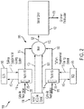
FIG. 2 illustrates the aircraft air conditioning system ofFIG. 1 operating in a recirculation ground maintenance mode that invokes a lower cooling zone according to a non-limiting embodiment; -
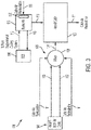
FIG. 3 illustrates the aircraft air conditioning system ofFIG. 1 operating in a recirculation ground maintenance mode that invokes an upper cooling zone according to a non-limiting embodiment; -
FIG. 4 illustrates the aircraft air conditioning system ofFIG. 1 operating in a recirculation ground maintenance mode that invokes a combination of upper and lower cooling zones according to a non-limiting embodiment; and -
FIG. 5 is a flow diagram illustrating a method of operating an aircraft air conditioning system in a recirculation ground maintenance mode according to a non-limiting embodiment. - A detailed description of one or more embodiments of the disclosed apparatus and method are presented herein by way of exemplification and not limitation with reference to the Figures.
- Airline maintenance operations sometimes require minimal staff onboard for cleaning procedures and maintenance tasks. In order to keep a habitable environment, many times the full ECS (including the ECS PACKS) is run along with the SCS to provide conditioned air supply into the cabin and flight deck. The ECS air conditioning PACKS represent a significant load on the ECS and require a substantial amount of power to operate. Therefore, operating the ECS conditioning PACKS consumes a large amount of fuel. However, in instances where maintenance operations are performed, overall occupancy of the aircraft is very low (only a few people on board) and thus operation of the full ECS is unnecessary.
- One or more non-limiting embodiments described herein relate to aircraft air conditioning system configured to selectively initiate a recirculation ground maintenance mode configured to provide cool air while reducing the power to the ECS. The recirculation ground maintenance mode controls flow of recirculated cabin air and cooled recirculated cabin air through a recirculation circuit without operating the ECS at full capacity. For example, the ram air system of the ECS can be operated without operating the ECS PACKS. The ram circuit can contain additional heat exchanges tied directly or via coupled fluid loops to the Supplemental Cooling System (SCS). In this manner, the aircraft cabin can be cooled without operating the ECS at full capacity, thereby significantly reducing fuel costs and improving power efficiency.
- In one or more non-limiting embodiments, the recirculation ground maintenance mode is configured to invoke a plurality of different cooling zones of the aircraft air conditioning system. The different cooling zones include, for example, a lower cooling zone, an upper cooling zone, and a combined upper and lower cooling zone. Selecting or deselecting the different cooling zones controls the flow of the recirculated cabin air and cooled recirculated cabin air through the recirculation circuit. A particular zone can be selected based on a desired or target temperature of the aircraft cabin. In this manner, the precision of the aircraft cabin temperature can be improved without requiring full operating capacity of the ECS as described herein.
- With reference now to
FIG. 1 , an aircraftair conditioning system 100 is illustrated according to a non-limiting embodiment. Theair conditioning system 100 in configured to selectively initiate a recirculation ground maintenance mode configured to control a temperature of anaircraft cabin 102. The aircraftair conditioning system 100 includes an environmental control system (ECS) 104, acabin recirculation system 105, the supplemental cooling system (SCS) 106, apower system 108, and acontroller 150. - The ECS 104 includes one or
more ECS outlets 103 configured to introduce fresh air into the aircraftair condition system 100. The ECS 104 includes one or more pressurization air cycle kits (PACKS) 109, aram circuit 110, and aram air fan 112. In one or more non-limiting embodiments, an individual PACK 109 includes an air cycle machine (ACM), bleed air source (not shown), and mixing valves (not shown). The PACKS 109 condition bleed air delivered thereto via the ACM to remove excessive heat, and supplies the conditioned air to thecabin 102 at a desired temperature. In one or more embodiments, the output of the PACKS 109 are substantially reduced or the PACKS 109 are completely deactivated when the recirculation ground maintenance mode is activated, as described in greater detail below. - A
ram fan 112 included in theram circuit 110 is configured to draw fresh air through theram circuit 110. In one or more embodiments, theram fan 112 is controlled independently from the PACKS 109. Accordingly, the PACKS 109 can be deactivated while activating theram fan 112 to draw air through theram circuit 110. The air source can be adapted to generate the fresh air at an elevated pressure, for example, at a pressure of about 1.25 bar to about 3.5 bar. Furthermore, the fresh air provided by the elevated pressure air source can have a temperature of about +200° C. The fresh air can include bleed air generated by the aircraft engine or compressed air generated by thepower system 108 or a cabin air compressor (sometimes referred to as a cabin air supercharger). - The
cabin recirculation system 105 includes a lower cooling zone and an upper cooling zone. The cooling zones can be selective invoked or activated to achieve different cooling temperatures. For example, the upper cooling zone can be invoked or selected without invoking or selecting the lower cooling zone to achieve a first cooling temperature or the highest cooling temperature. The lower cooling zone can be invoked or selected without invoking or selecting the upper cooling zone to achieve a second cooling temperature or a medium cooling temperature. The lower and upper cooling zones can be both be invoked (i.e., activated simultaneously) to achieve a third cooling temperature or the coldest cooling temperature. The different zones also allow for fault toleration. For example, if a component in the upper cooling zone fails, the lower cooling zone can still be invoked to provide cabin cooling capabilities. - The lower cooling zone includes one or more
lower recirculation fans 116, one or more lowerrecirculation heat exchangers 118, and anair manifold 120. Thelower recirculation fans 116 are selectively operable to draw recirculatedcabin air 111 through a lowerrecirculation heat exchanger 118. The lowerrecirculation heat exchanger 118 is configured to recirculate a heat transfer fluid 113 (sometimes referred to as coolant). Accordingly, heat from the recirculatedcabin air 111 is transferred to theheat transfer fluid 113, thereby facilitating the lowerrecirculation heat exchange 118 to output cooled recirculatedcabin air 115 that can be delivered to theair manifold 120. In one or more embodiments, the input recirculatedcabin air 111 has a temperature of about 110 degrees Fahrenheit (°F) (about 43 degrees Celsius (°C)), and output cooled recirculatedcabin air 115 has a temperature that is reduced to about 60°F (about 15°C). - The manifold 120 is configured to receive to produce cooled
cabin supply air 121. The cooledcabin supply air 121 is then delivered to theaircraft cabin 102. When theECS 104 is switched on (e.g., the recirculation ground maintenance mode is deactivated), the manifold can mix the airflow delivered by theECS 104 with the recirculatedcabin air 111 and/or the cooled recirculatedcabin air 115. - The
SCS 106 is in fluid communication with thecabin recirculation system 105 and theaircraft cabin 102. TheSCS 106 supplements aircraft cooling operations provided byECS 104. TheSCS 106 includes a recirculation heat transfer fluid path that recirculates theheat transfer fluid 113. Theheat transfer fluid 113 can be used to cool the aircraft galley and/or various electronics. In one or more embodiments, theSCS 106 operates independently from theECS 104 and thecabin recirculation system 105. Accordingly, theheat transfer fluid 113 can be selectively provided to one or more targeted lowerrecirculation heat exchangers 118 to facilitate cooling of the recirculatedcabin air 111. - The
power system 108 is configured to selectively deliver power to theECS 104, theSCS 106, and thecabin recirculation system 105. For example, thepower system 108 is configured to selectively deliver power to theram fan 112 and therecirculation fans power system 108 can include an auxiliary power unit (APU) or external aircraft ground support equipment (simply referred to as an external power system). - The
controller 150 is in signal communication with thepower system 108 and is configured to initiate a recirculation ground maintenance mode. The recirculation ground maintenance mode controls flow of the recirculatedcabin air 111 and cooled recirculatedcabin air 115 through thecabin recirculation system 105 without operating theECS 104 at full capacity (e.g., without operating the PACKS 109). The ability to cool thecabin 102 without operating theECS 104 at full capacity significantly reduces fuel costs and improves power efficiency, while also prolonging the useful life of the ECS by reducing loads on the ECS components (e.g., compressor, fans, pumps, etc.). In one or more non-limiting embodiments, the recirculation ground maintenance mode is configured to invoke a plurality of different cooling zones of the aircraftair conditioning system 100. In one or more non-limiting embodiments, the cooling zones include a lower cooling zone, an upper cooling zone and a combined upper and lower cooling zone. Selecting or deselecting the different cooling zones controls the flow of the recirculatedcabin air 111 and cooled recirculatedcabin air 115 through thecabin recirculation system 105. The zones invoked can be selected based on a desired or target temperature of theaircraft cabin 102. For example, thecontroller 150 can store one or more target cabin temperatures and can receive atemperature signal 152 indicating a measured temperature of thecabin 102. In this manner, thecontroller 150 can invoke the lower cooling zone, the upper cooling zone, and/or a combination of the lower and upper cooling zones based on a comparison between a target cabin temperature and thetemperature signal 152. Accordingly, the precision of the aircraft cabin temperature can be improved without requiring full operating capacity of theECS 104. - With reference to
FIG. 2 , operation of the recirculation ground maintenance mode with the lower cooling zone invoked. In response to invoking the lower cooling zone, thecontroller 150 adjusts a SCS liquid circuit diverter valve (not shown) into the first position so as to deliver theheat transfer fluid 113 to the lowerrecirculation heat exchanger 118, resulting in cool air delivered to themanifold 120. In addition, the ECS PACKS 109 are deactivated, thereby stopping flow to themixer 120 as indicated by the dashedoutput 103. Accordingly, the manifold 120 receives the cooled recirculated cabin air 115 (e.g., lower cooled recirculated cabin air 115) and produces the cooledcabin supply air 121 which is delivered to theaircraft cabin 102. - With reference to
FIG. 3 , operation of the recirculation ground maintenance mode is illustrated with the upper cooling zone invoked. Anupper recirculation fan 130 andupper heat exchanger 133 is also coupled to the cabin path 127. As is the case when invoking the lower cooling zone, the ECS PACKS 109 are deactivated, thereby stopping flow to themixer 120 as indicated by the dashedoutput 103. Theupper recirculation fan 130 drawscabin recirculation air 111 to theupper heat exchange 133, which in turns outputs cooled recirculation air 115 (i.e., upper cooled recirculation air 115) directly into a low pressure distribution system and into thecabin 102. In addition, the manifold 120 receives the recirculatedcabin air 111 to produce the cooledcabin supply air 121 that is also delivered to thecabin 102. - With reference to
FIG. 4 , operation of the recirculation ground maintenance mode is illustrated while invoking a combination of the upper and lower cooling zones. In response to invoking the upper and lower cooling zone, the ECS PACKS 109 are deactivated to stop flow to themixer 120 as indicated by the dashedoutput 103. Cabin air is then simultaneously delivered to the lower cooling zone and the upper cooling zone. The manifold 120 receives the cooled recirculatedcabin air 115 to produce the cooledcabin supply air 121 that is delivered to theaircraft cabin 102. In addition, cooled recirculatedcabin air 115 is also delivered to theaircraft cabin 102. Because thecabin 102 receives cooledcabin supply air 121 having a reduced temperature (due to delivering cooled recirculatedcabin air 115 into the manifold 120) while also directly receiving cooled recirculatedcabin air 115 from theupper heat exchanger 133, the cabin temperature can be further reduced compared to the invoking only the lower cooling zone (seeFIG. 2 ) or only the upper cooling zone (seeFIG. 3 ). - Turning now to
FIG. 5 , a method of operating an aircraft air conditioning system in a recirculation ground maintenance mode is illustrated according to a non-limiting embodiment. The method starts atoperation 500, and atoperation 502 the recirculation ground maintenance mode is initiated. Atoperation 504, power delivered to the PACKS of the ECS system is reduced. In one or more non-limiting embodiments, the power is completely disconnected such that the PACKS are deactivated. Atoperation 506, the ram air system is activated and the ram fan associated with the ram air system is initiated. Atoperation 508, the SCS is activated, and at operation 510 a determination is made as to whether the lower and upper recirculation zone is selected. When the lower and upper recirculation zone is selected, the lower recirculation fans associated with the lower cooling zone are initiated along with the upper recirculation fan associated with the upper cooling zone atoperation 512, and the method ends atoperation 514. - When, however, the lower and upper recirculation zone is not selected at
operation 510, a determination is made atoperation 516 as to whether the lower recirculation zone is selected. When only the lower recirculation zone is selected, the method proceeds tooperation 518 to activate the lower recirculation fans and deactivate the upper recirculation fan associated with the upper cooling zone, and the method ends at operation ends 514. - When, however, the lower recirculation zone is not selected at
operation 516, the method proceeds tooperation 520 and selects the upper recirculation zone. Atoperation 522, the lower recirculation fans are deactivated and the upper recirculation fan associated with the upper cooling zone is activated, and the method ends atoperation 514. - As described herein, one or more non-limiting embodiments provide an aircraft air conditioning system configured to selectively initiate a cooling recirculation ground maintenance mode. The recirculation ground maintenance mode controls flow of recirculated cabin air and cooled recirculated cabin air through a recirculation circuit without operating the ECS at full capacity. For example, the ram air system of the ECS can be operated in conjunction with a supplemental cooling system (SCS) without operating the ECS PACKS. In this manner, the aircraft cabin can be cooled without operating the ECS at full capacity, thereby significantly reducing fuel costs and improving power efficiency.
- The term "about" is intended to include the degree of error associated with measurement of the particular quantity based upon the equipment available at the time of filing the application.
- The terminology used herein is for the purpose of describing particular embodiments only and is not intended to be limiting of the present disclosure. As used herein, the singular forms "a", "an" and "the" are intended to include the plural forms as well, unless the context clearly indicates otherwise. It will be further understood that the terms "comprises" and/or "comprising," when used in this specification, specify the presence of stated features, integers, steps, operations, elements, and/or components, but do not preclude the presence or addition of one or more other features, integers, steps, operations, element components, and/or groups thereof.
- While the present disclosure has been described with reference to an exemplary embodiment or embodiments, it will be understood by those skilled in the art that various changes may be made without departing from the scope of the invention as defined by the claims. In addition, many modifications may be made to adapt a particular situation or material to the teachings of the present disclosure without departing from the scope of the claims. Therefore, it is intended that the present disclosure not be limited to the particular embodiment disclosed as the best mode contemplated for carrying out this present disclosure, but that the present disclosure will include all embodiments falling within the scope of the claims.
Claims (15)
- An aircraft air conditioning system comprising:a lower cooling zone including a lower recirculation heat exchanger (118), the lower recirculation heat exchanger configured to receive cabin air from a cabin and to convert the cabin air into lower cooled recirculated cabin air;an upper cooling zone including an upper recirculation heat exchanger (133), the upper recirculation heat exchanger configured to receive the cabin air from the cabin and to convert the cabin air into upper cooled recirculated cabin air;a power system (108) configured to selectively deliver power to the lower cooling zone and the upper cooling zone; anda controller (150) in signal communication with the power system, the controller configured to determine a target temperature of the cabin and invokes a recirculation ground maintenance mode that commands the power system to deliver power to one or both of the lower cooling zone and the upper cooling zone so that a temperature of the cabin reaches the target temperature.
- The aircraft air conditioning system of claim 1, further comprising:a manifold (120);a ram air circuit (110) in fluid communication with the manifold,a pressurization air cycle kit, PACK, (109) in signal communication with the power system to selectively receive the power; andwherein in response to invoking the recirculation ground maintenance mode, the controller commands the power system to disconnect the power to the PACK, and the manifold outputs cooled cabin supply air that is delivered to the cabin to reduce the cabin temperature.
- The aircraft air conditioning system of claim 2, further comprising:a lower recirculation fan (116) is configured to deliver a first portion of the cabin air to the lower recirculation heat exchanger (118) in response to receiving the power from the power system, and wherein the lower recirculation heat exchanger is configured to convert the first portion of the cabin air into the lower cooled recirculated cabin air; andan upper recirculation fan (130) configured to deliver a second portion of the cabin air to the upper recirculation heat exchanger (133) in response to receiving the power from the power system, and convert the second portion of the cabin air into the upper cooled recirculated cabin air.
- The aircraft air conditioning system of claim 3, further comprising a supplemental cooling system, SCS, (106) configured to deliver a heat transfer fluid to the lower recirculation heat exchanger and the upper recirculation heat exchanger.
- The aircraft air conditioning system of claim 4, wherein in response to invoking the lower cooling zone, the controller (150) commands the power system to deliver power to the lower recirculation fan while commanding the power system to disconnect from power to the upper recirculation fan, and optionally, wherein in response in response to invoking the lower cooling zone, the lower cooled recirculated cabin air is delivered to the manifold to output the cooled cabin supply air.
- The aircraft air conditioning system of claim 4, wherein in response to invoking the upper cooling zone, the controller (150) commands the power system to deliver power to the upper recirculation fan while commanding the power system to disconnect from power to the lower recirculation fan, and optionally wherein in response to invoking the upper cooling zone, the upper cooled recirculated cabin air is delivered to the cabin while the lower cooled recirculated cabin air is blocked from reaching the manifold.
- The aircraft air conditioning system of claim 6, wherein in response in response to invoking the upper cooling zone, the recirculated cabin air (115) is delivered to the manifold to output the cooled cabin supply air (121).
- The aircraft air conditioning system of claim 4, wherein in response to invoking a combination of the lower and upper cooling zones, the controller commands the power system to deliver power to the lower and upper recirculation fans, and optionally wherein in response to invoking the combination of the lower and upper cooling zones, the lower cooled recirculated cabin air is delivered to the manifold to output the cooled cabin supply air and the upper cooled recirculated cabin air is delivered to the cabin.
- A method of controlling an aircraft air conditioning system comprising, the method comprising:delivering cabin air to a lower recirculation heat exchanger (118) included in a lower cooling zone;delivering the cabin air to an upper recirculation heat exchanger (133) included in an upper cooling zone including, the upper recirculation heat exchanger configured to receive the cabin air from the cabin and to convert the cabin air into upper cooled recirculated cabin air;generating power via a power system (108); anddetermining, via a controller (150), a target temperature of the cabin; andinvoking, via the controller, a recirculation ground maintenance mode to command the power system to deliver power to one or both of the lower cooling zone and the upper cooling zone so that a temperature of the cabin reaches the target temperature.
- The method of claim 9, further comprising:
commanding, via the controller, the power system to disconnect the power to a pressurization air cycle kit, PACK, (109) in response to invoking the recirculation ground maintenance mode. - The method of claim 10, further comprising selectively delivering a first portion of the cabin air to the lower cooling zone and selectively delivering a second portion of the cabin air to the upper cooling zone independently from the first portion of the cabin air.
- The method of claim 11, further comprising:delivering power from the power system to a lower recirculation fan (116) included in the lower cooling zone; andand delivering the first portion cabin air to the lower recirculation heat exchanger in response to powering the lower recirculation fan, and optionally further comprising:delivering power from the power system to an upper recirculation fan (130) included in the upper recirculation zone; andand delivering the second portion of the cabin air to the upper recirculation heat exchanger in response to powering the upper recirculation fan.
- The method of claim 12, wherein in response to invoking the lower cooling zone, the controller commands the power system to deliver power to the lower recirculation fan while commanding the power system to disconnect from power to the upper recirculation fan, and optionally wherein in response to invoking the upper cooling zone, the controller commands the power system to deliver power to the upper recirculation fan while commanding the power system to disconnect from power to the lower recirculation fan.
- The method of claim 13, wherein in response to invoking a combination of the lower and upper cooling zones, the controller commands the power system to deliver power to the lower and upper recirculation fans.
- The method of claim 14, wherein in response to invoking a combination of the lower and upper cooling zones, simultaneously delivering the first portion of the cabin air to the lower cooling zone and the second portion of the cabin air to the upper cooling zone.
Applications Claiming Priority (1)
| Application Number | Priority Date | Filing Date | Title |
|---|---|---|---|
| US17/116,224 US12065250B2 (en) | 2020-12-09 | 2020-12-09 | Recirculation ground maintenance mode |
Publications (2)
| Publication Number | Publication Date |
|---|---|
| EP4011778A1 true EP4011778A1 (en) | 2022-06-15 |
| EP4011778B1 EP4011778B1 (en) | 2026-05-06 |
Family
ID=78822664
Family Applications (1)
| Application Number | Title | Priority Date | Filing Date |
|---|---|---|---|
| EP21212619.7A Active EP4011778B1 (en) | 2020-12-09 | 2021-12-06 | Recirculation ground maintenance mode |
Country Status (2)
| Country | Link |
|---|---|
| US (2) | US12065250B2 (en) |
| EP (1) | EP4011778B1 (en) |
Families Citing this family (3)
| Publication number | Priority date | Publication date | Assignee | Title |
|---|---|---|---|---|
| US12337973B2 (en) * | 2022-01-17 | 2025-06-24 | The Boeing Company | Methods, systems, and apparatuses for reducing ozone concentration and reducing VOC concentration in aircraft cabin environment recirculated airflow |
| US12428164B2 (en) * | 2022-05-16 | 2025-09-30 | General Electric Company | Environmental control system having a fuel cell assembly |
| US12377715B2 (en) | 2023-04-24 | 2025-08-05 | Hamilton Sundstrand Corporation | Hybrid environmental control system for split cooling |
Citations (6)
| Publication number | Priority date | Publication date | Assignee | Title |
|---|---|---|---|---|
| US7121100B2 (en) * | 2003-09-09 | 2006-10-17 | The Boeing Company | High efficiency aircraft cabin air supply cooling system |
| DE102008035123A1 (en) * | 2008-07-28 | 2010-02-11 | Airbus Deutschland Gmbh | System and method for the air conditioning of an aircraft cabin |
| US20130327891A1 (en) * | 2012-06-06 | 2013-12-12 | Wei Zhang | Environmental control system and methods of operating same |
| US20170144767A1 (en) * | 2015-11-20 | 2017-05-25 | Hamilton Sundstrand Corporation | Heat exchanger |
| EP3333078A1 (en) * | 2016-12-08 | 2018-06-13 | Hamilton Sundstrand Corporation | Air distribution system with recirculating zone trim tec |
| EP3489143A1 (en) * | 2017-11-28 | 2019-05-29 | Hamilton Sundstrand Corporation | Aircraft cabin air monitor |
Family Cites Families (16)
| Publication number | Priority date | Publication date | Assignee | Title |
|---|---|---|---|---|
| US4263786A (en) | 1979-07-10 | 1981-04-28 | The Boeing Company | Fuel conserving air-conditioning apparatus and method for aircraft |
| US4262495A (en) | 1979-09-20 | 1981-04-21 | The Boeing Company | Cabin-air recirculation system powered by cabin-to-ambient pressure differential |
| US4835977A (en) * | 1983-11-18 | 1989-06-06 | Teledyne Industries, Inc. | Apparatus and method of air-conditioning parked aircraft |
| DE19509773C1 (en) * | 1995-03-17 | 1996-06-27 | Daimler Benz Aerospace Airbus | Ventilating system for reducing concentration of impurities in aircraft passenger area |
| US6209330B1 (en) * | 1999-05-17 | 2001-04-03 | Caterpillar Inc. | Modular air handling system and method for providing cooling |
| US6418744B1 (en) * | 2001-04-09 | 2002-07-16 | Earnest J. Neal | Method and apparatus for containing an ambient climate control system |
| US6681591B2 (en) | 2001-10-19 | 2004-01-27 | Hamilton Sundstrand | Cabin air temperature control with cooling of recirculated air |
| GB2409718A (en) * | 2003-06-06 | 2005-07-06 | David Whittingham | Aircraft air disinfection system |
| US7685838B2 (en) * | 2006-03-09 | 2010-03-30 | Dew Engineering And Development Ulc | Ground-based aircraft air conditioner with thermal storage |
| EP1857363A1 (en) * | 2006-05-19 | 2007-11-21 | Lebrun Nimy | Temperature regulating device |
| US20080264084A1 (en) | 2007-04-25 | 2008-10-30 | Honeywell International Inc. | Pressurized closed cooling system |
| DE102008053668B4 (en) * | 2008-10-29 | 2010-11-25 | Airbus Deutschland Gmbh | System and method for air conditioning an aircraft cabin with improved cooling performance |
| WO2016189421A1 (en) * | 2015-05-22 | 2016-12-01 | Bombardier Inc. | Airflow management in cabin of aircraft |
| US20180148181A1 (en) * | 2016-11-30 | 2018-05-31 | Hamilton Sundstrand Corporation | Air distribution manifold with integral multizone tec trim system |
| US12275536B2 (en) * | 2019-10-24 | 2025-04-15 | Pratt & Whitney Canada Corp. | Aircraft power supply arrangements |
| GB202018377D0 (en) * | 2020-11-23 | 2021-01-06 | Rolls Royce Plc | Cabin blower system |
-
2020
- 2020-12-09 US US17/116,224 patent/US12065250B2/en active Active
-
2021
- 2021-12-06 EP EP21212619.7A patent/EP4011778B1/en active Active
-
2024
- 2024-07-17 US US18/775,044 patent/US12503240B2/en active Active
Patent Citations (6)
| Publication number | Priority date | Publication date | Assignee | Title |
|---|---|---|---|---|
| US7121100B2 (en) * | 2003-09-09 | 2006-10-17 | The Boeing Company | High efficiency aircraft cabin air supply cooling system |
| DE102008035123A1 (en) * | 2008-07-28 | 2010-02-11 | Airbus Deutschland Gmbh | System and method for the air conditioning of an aircraft cabin |
| US20130327891A1 (en) * | 2012-06-06 | 2013-12-12 | Wei Zhang | Environmental control system and methods of operating same |
| US20170144767A1 (en) * | 2015-11-20 | 2017-05-25 | Hamilton Sundstrand Corporation | Heat exchanger |
| EP3333078A1 (en) * | 2016-12-08 | 2018-06-13 | Hamilton Sundstrand Corporation | Air distribution system with recirculating zone trim tec |
| EP3489143A1 (en) * | 2017-11-28 | 2019-05-29 | Hamilton Sundstrand Corporation | Aircraft cabin air monitor |
Non-Patent Citations (2)
| Title |
|---|
| ANONYMOUS: "Environmental control system - Wikipedia", 2 March 2019 (2019-03-02), pages 1 - 5, XP055907537, Retrieved from the Internet <URL:https://web.archive.org/web/20190302201434/https://en.wikipedia.org/wiki/Environmental_control_system> [retrieved on 20220331] * |
| UNKNOWN: "Canadair Regional Jet 100/200 - Environmental Control System", 19 August 2019 (2019-08-19), pages 1 - 39, XP055907523, Retrieved from the Internet <URL:https://www.smartcockpit.com/docs/Bombardier_CRJ_200-Environmental_Control_System.pdf> [retrieved on 20220331] * |
Also Published As
| Publication number | Publication date |
|---|---|
| EP4011778B1 (en) | 2026-05-06 |
| US12503240B2 (en) | 2025-12-23 |
| US20240367801A1 (en) | 2024-11-07 |
| US12065250B2 (en) | 2024-08-20 |
| US20220177141A1 (en) | 2022-06-09 |
Similar Documents
| Publication | Publication Date | Title |
|---|---|---|
| US12503240B2 (en) | Recirculation ground maintenance mode | |
| US10752365B2 (en) | Method and device for thermal control of a plurality of cabins of a vehicle | |
| US7523622B2 (en) | Aircraft galley chiller system | |
| EP1295789B1 (en) | Environmental control system | |
| CN103079956B (en) | Aircraft air-conditioning system including the kind of refrigeration cycle separated | |
| EP3173337B1 (en) | Aircraft air conditioning system with ambient air supply and method for operating such an aircraft air conditioning system | |
| US20150251765A1 (en) | Low-pressure bleed air aircraft environmental control system | |
| EP3620378B1 (en) | Air-driven vapor cycle refrigeration system | |
| US9221543B2 (en) | Compressor/turbine arrangement, air conditioning unit and method for operating a compressor/turbine arrangement | |
| EP1801009B1 (en) | Integrated control system for combined galley refrigeration unit and cabin air conditioning system | |
| US8225622B2 (en) | Cooling system and freight container | |
| EP1902950A1 (en) | Avionics cooling | |
| US9592916B2 (en) | Aircraft air conditioning system and method for controlling an aircraft air conditioning system using a bypass valve | |
| US9011219B2 (en) | System and method for air-conditioning an aircraft cabin | |
| BR102014028182B1 (en) | AIR CYCLE MACHINE ASSEMBLY SYSTEM FOR AN AIRCRAFT, AND, METHOD FOR IMPROVING LOW PRESSURE INLET COOLING PERFORMANCE OF AN AIR CYCLE MACHINE ASSEMBLY SYSTEM | |
| CN101378959A (en) | Cooling system | |
| CN107548369A (en) | Aircraft air-conditioning system and the method for operating this aircraft air-conditioning system | |
| US20140345305A1 (en) | Aircraft cooling system and method for operating an aircraft cooling system | |
| CN103562067A (en) | Air conditioning system for an aircraft passenger compartment | |
| EP3575216A1 (en) | Air supply management system for auxiliary power unit | |
| US20130239598A1 (en) | Aircraft environmental control system with conditioned heat sink | |
| US9821914B2 (en) | Aircraft air conditioning system and method of operating an aircraft air conditioning system | |
| US12071247B2 (en) | Trim module with thermoelectric cooler | |
| EP3138774A1 (en) | Aircraft air conditioning system with a reduced process air demand | |
| US20240300549A1 (en) | Hyperloop environmental control system |
Legal Events
| Date | Code | Title | Description |
|---|---|---|---|
| PUAI | Public reference made under article 153(3) epc to a published international application that has entered the european phase |
Free format text: ORIGINAL CODE: 0009012 |
|
| STAA | Information on the status of an ep patent application or granted ep patent |
Free format text: STATUS: THE APPLICATION HAS BEEN PUBLISHED |
|
| AK | Designated contracting states |
Kind code of ref document: A1 Designated state(s): AL AT BE BG CH CY CZ DE DK EE ES FI FR GB GR HR HU IE IS IT LI LT LU LV MC MK MT NL NO PL PT RO RS SE SI SK SM TR |
|
| STAA | Information on the status of an ep patent application or granted ep patent |
Free format text: STATUS: REQUEST FOR EXAMINATION WAS MADE |
|
| 17P | Request for examination filed |
Effective date: 20221215 |
|
| RBV | Designated contracting states (corrected) |
Designated state(s): AL AT BE BG CH CY CZ DE DK EE ES FI FR GB GR HR HU IE IS IT LI LT LU LV MC MK MT NL NO PL PT RO RS SE SI SK SM TR |
|
| STAA | Information on the status of an ep patent application or granted ep patent |
Free format text: STATUS: EXAMINATION IS IN PROGRESS |
|
| 17Q | First examination report despatched |
Effective date: 20230929 |
|
| GRAP | Despatch of communication of intention to grant a patent |
Free format text: ORIGINAL CODE: EPIDOSNIGR1 |
|
| STAA | Information on the status of an ep patent application or granted ep patent |
Free format text: STATUS: GRANT OF PATENT IS INTENDED |
|
| GRAJ | Information related to disapproval of communication of intention to grant by the applicant or resumption of examination proceedings by the epo deleted |
Free format text: ORIGINAL CODE: EPIDOSDIGR1 |
|
| STAA | Information on the status of an ep patent application or granted ep patent |
Free format text: STATUS: EXAMINATION IS IN PROGRESS |
|
| INTG | Intention to grant announced |
Effective date: 20251021 |
|
| INTC | Intention to grant announced (deleted) | ||
| GRAJ | Information related to disapproval of communication of intention to grant by the applicant or resumption of examination proceedings by the epo deleted |
Free format text: ORIGINAL CODE: EPIDOSDIGR1 |
|
| GRAP | Despatch of communication of intention to grant a patent |
Free format text: ORIGINAL CODE: EPIDOSNIGR1 |
|
| GRAP | Despatch of communication of intention to grant a patent |
Free format text: ORIGINAL CODE: EPIDOSNIGR1 |
|
| STAA | Information on the status of an ep patent application or granted ep patent |
Free format text: STATUS: GRANT OF PATENT IS INTENDED |
|
| INTG | Intention to grant announced |
Effective date: 20260115 |
|
| GRAS | Grant fee paid |
Free format text: ORIGINAL CODE: EPIDOSNIGR3 |
|
| GRAA | (expected) grant |
Free format text: ORIGINAL CODE: 0009210 |
|
| STAA | Information on the status of an ep patent application or granted ep patent |
Free format text: STATUS: THE PATENT HAS BEEN GRANTED |
|
| AK | Designated contracting states |
Kind code of ref document: B1 Designated state(s): AL AT BE BG CH CY CZ DE DK EE ES FI FR GB GR HR HU IE IS IT LI LT LU LV MC MK MT NL NO PL PT RO RS SE SI SK SM TR |
|
| REG | Reference to a national code |
Ref country code: CH Ref legal event code: F10 Free format text: ST27 STATUS EVENT CODE: U-0-0-F10-F00 (AS PROVIDED BY THE NATIONAL OFFICE) Effective date: 20260506 Ref country code: GB Ref legal event code: FG4D |