EP4011662A1 - A side impact restraint protection system for a vehicle - Google Patents
A side impact restraint protection system for a vehicle Download PDFInfo
- Publication number
- EP4011662A1 EP4011662A1 EP20213774.1A EP20213774A EP4011662A1 EP 4011662 A1 EP4011662 A1 EP 4011662A1 EP 20213774 A EP20213774 A EP 20213774A EP 4011662 A1 EP4011662 A1 EP 4011662A1
- Authority
- EP
- European Patent Office
- Prior art keywords
- door
- safety
- vehicle
- safety structure
- protection system
- Prior art date
- Legal status (The legal status is an assumption and is not a legal conclusion. Google has not performed a legal analysis and makes no representation as to the accuracy of the status listed.)
- Granted
Links
Images




Classifications
-
- B—PERFORMING OPERATIONS; TRANSPORTING
- B60—VEHICLES IN GENERAL
- B60J—WINDOWS, WINDSCREENS, NON-FIXED ROOFS, DOORS, OR SIMILAR DEVICES FOR VEHICLES; REMOVABLE EXTERNAL PROTECTIVE COVERINGS SPECIALLY ADAPTED FOR VEHICLES
- B60J5/00—Doors
- B60J5/04—Doors arranged at the vehicle sides
- B60J5/042—Reinforcement elements
- B60J5/0456—Behaviour during impact
- B60J5/0459—Active coupling of the reinforcement elements to the door or to the vehicle body, e.g. through releasing of pressurized gas
-
- B—PERFORMING OPERATIONS; TRANSPORTING
- B60—VEHICLES IN GENERAL
- B60J—WINDOWS, WINDSCREENS, NON-FIXED ROOFS, DOORS, OR SIMILAR DEVICES FOR VEHICLES; REMOVABLE EXTERNAL PROTECTIVE COVERINGS SPECIALLY ADAPTED FOR VEHICLES
- B60J5/00—Doors
- B60J5/04—Doors arranged at the vehicle sides
- B60J5/047—Doors arranged at the vehicle sides characterised by the opening or closing movement
- B60J5/0477—Doors arranged at the vehicle sides characterised by the opening or closing movement with two doors opening in opposite direction
- B60J5/0479—Doors arranged at the vehicle sides characterised by the opening or closing movement with two doors opening in opposite direction without B-pillar or releasable B-pillar, i.e. the pillar is moving with door
-
- B—PERFORMING OPERATIONS; TRANSPORTING
- B60—VEHICLES IN GENERAL
- B60J—WINDOWS, WINDSCREENS, NON-FIXED ROOFS, DOORS, OR SIMILAR DEVICES FOR VEHICLES; REMOVABLE EXTERNAL PROTECTIVE COVERINGS SPECIALLY ADAPTED FOR VEHICLES
- B60J5/00—Doors
- B60J5/04—Doors arranged at the vehicle sides
- B60J5/042—Reinforcement elements
- B60J5/0422—Elongated type elements, e.g. beams, cables, belts or wires
- B60J5/0423—Elongated type elements, e.g. beams, cables, belts or wires characterised by position in the lower door structure
- B60J5/0425—Elongated type elements, e.g. beams, cables, belts or wires characterised by position in the lower door structure the elements being arranged essentially horizontal in the centre of the lower door structure
-
- B—PERFORMING OPERATIONS; TRANSPORTING
- B60—VEHICLES IN GENERAL
- B60J—WINDOWS, WINDSCREENS, NON-FIXED ROOFS, DOORS, OR SIMILAR DEVICES FOR VEHICLES; REMOVABLE EXTERNAL PROTECTIVE COVERINGS SPECIALLY ADAPTED FOR VEHICLES
- B60J5/00—Doors
- B60J5/04—Doors arranged at the vehicle sides
- B60J5/042—Reinforcement elements
- B60J5/0422—Elongated type elements, e.g. beams, cables, belts or wires
- B60J5/0437—Elongated type elements, e.g. beams, cables, belts or wires characterised by the attachment means to the door, e.g. releasable attachment means
-
- B—PERFORMING OPERATIONS; TRANSPORTING
- B60—VEHICLES IN GENERAL
- B60J—WINDOWS, WINDSCREENS, NON-FIXED ROOFS, DOORS, OR SIMILAR DEVICES FOR VEHICLES; REMOVABLE EXTERNAL PROTECTIVE COVERINGS SPECIALLY ADAPTED FOR VEHICLES
- B60J5/00—Doors
- B60J5/04—Doors arranged at the vehicle sides
- B60J5/042—Reinforcement elements
- B60J5/0422—Elongated type elements, e.g. beams, cables, belts or wires
- B60J5/0438—Elongated type elements, e.g. beams, cables, belts or wires characterised by the type of elongated elements
- B60J5/044—Elongated type elements, e.g. beams, cables, belts or wires characterised by the type of elongated elements the elements being flexible, e.g. belts, cables or wires
-
- B—PERFORMING OPERATIONS; TRANSPORTING
- B60—VEHICLES IN GENERAL
- B60J—WINDOWS, WINDSCREENS, NON-FIXED ROOFS, DOORS, OR SIMILAR DEVICES FOR VEHICLES; REMOVABLE EXTERNAL PROTECTIVE COVERINGS SPECIALLY ADAPTED FOR VEHICLES
- B60J5/00—Doors
- B60J5/04—Doors arranged at the vehicle sides
- B60J5/042—Reinforcement elements
- B60J5/0422—Elongated type elements, e.g. beams, cables, belts or wires
- B60J5/0438—Elongated type elements, e.g. beams, cables, belts or wires characterised by the type of elongated elements
- B60J5/0443—Beams
- B60J5/0447—Beams formed of several elements arranged in parallel
-
- B—PERFORMING OPERATIONS; TRANSPORTING
- B60—VEHICLES IN GENERAL
- B60J—WINDOWS, WINDSCREENS, NON-FIXED ROOFS, DOORS, OR SIMILAR DEVICES FOR VEHICLES; REMOVABLE EXTERNAL PROTECTIVE COVERINGS SPECIALLY ADAPTED FOR VEHICLES
- B60J5/00—Doors
- B60J5/04—Doors arranged at the vehicle sides
- B60J5/042—Reinforcement elements
- B60J5/0456—Behaviour during impact
- B60J5/0458—Passive coupling of the reinforcement elements to the door or to the vehicle body
-
- B—PERFORMING OPERATIONS; TRANSPORTING
- B62—LAND VEHICLES FOR TRAVELLING OTHERWISE THAN ON RAILS
- B62D—MOTOR VEHICLES; TRAILERS
- B62D25/00—Superstructure or monocoque structure sub-units; Parts or details thereof not otherwise provided for
- B62D25/04—Door pillars ; windshield pillars
-
- B—PERFORMING OPERATIONS; TRANSPORTING
- B60—VEHICLES IN GENERAL
- B60J—WINDOWS, WINDSCREENS, NON-FIXED ROOFS, DOORS, OR SIMILAR DEVICES FOR VEHICLES; REMOVABLE EXTERNAL PROTECTIVE COVERINGS SPECIALLY ADAPTED FOR VEHICLES
- B60J5/00—Doors
- B60J5/04—Doors arranged at the vehicle sides
- B60J5/047—Doors arranged at the vehicle sides characterised by the opening or closing movement
- B60J2005/0475—Doors arranged at the vehicle sides characterised by the opening or closing movement due to absence of the B-pillar
Definitions
- the present disclosure relates to a side impact restraint protection system for a vehicle.
- the side impact restraint protection system comprises a first side safety structure, a second side safety structure, a first structural element of a vehicle body structure of the vehicle, and a second structural element of the vehicle body structure.
- the first side safety structure is arranged in connection to a first side door of the vehicle and the second side safety structure is arranged in connection to a second side door of the vehicle.
- An object of the present disclosure is to provide a side impact restraint protection system where the previously mentioned problems are avoided. This object is at least partly achieved by the features of the independent claim.
- the dependent claims contain further developments of the side impact restraint protection system.
- the disclosure concerns a side impact restraint protection system for a vehicle, comprising a first side safety structure, a second side safety structure, a first structural element of a vehicle body structure of the vehicle, and a second structural element of the vehicle body structure.
- the first side safety structure is arranged in connection to a first side door of the vehicle and the second side safety structure is arranged in connection to a second side door of the vehicle.
- the first side door and the second side door are arranged to cover a common single door opening of the vehicle body structure in a closed door position.
- the first structural element is arranged in a position in front of the door opening in a longitudinal direction of the vehicle, and the second structural element is arranged in a position behind the door opening in the longitudinal direction.
- first side safety structure and the second side safety structure are configured to be releasably connected to each other via a connecting device, the first side safety structure is configured to be connected to the first structural element via a first connection member, and the second side safety structure is configured to be connected to the second structural element via a second connection member.
- the construction is providing a strong and safe design of the side impact restraint protection system suitable for meeting future legal requirements for crash strength, where the system is capturing impact energy efficiently.
- the side impact restraint protection system with this design can be made lightweight in construction and suitable for different vehicle constructions, as vehicle constructions without B-pillars. With the system, the door can be made more lightweight in construction without traditional heavy door beams.
- the system is with the releasable connection via the connecting device further enabling and simplifying opening of the side doors after a side impact event.
- the system comprises a first door beam arranged in the first side door, and/or a second door beam arranged in the second side door.
- the first door beam is extending between a roof beam structure and a sill structure of the vehicle body structure when the first side door is arranged in the closed door position.
- the second door beam is extending between the roof beam structure and the sill structure of the vehicle body structure when the second side door is arranged in the closed door position.
- the respective side doors are suitably connected to the roof beam structure and/or the sill structure with connection or locking devices for efficiently holding the door in the closed door position.
- the first door beam is configured for replacing a B-pillar of the vehicle body structure
- the second door beam is configured for replacing a B-pillar of the vehicle body structure.
- the door beams are designed to absorb impact load and for cooperating with the side safety structures and the car body structure for efficiently protecting occupants of the vehicle.
- the first side door is a front vehicle side door and the first door beam is arranged in connection to a rear edge of the first side door
- the second side door is a rear vehicle side door and the second door beam is arranged in connection to a front edge of the second side door.
- the first side safety structure is in a lateral direction of the vehicle arranged outside of the first door beam
- the second side safety structure is in a lateral direction of the vehicle arranged outside of the second door beam.
- the connecting device comprises a first connector part connected to the first side safety structure and a second connector part connected to the second side safety structure.
- the first connector part and the second connector part are configured for releasably connecting the first side safety structure and the second side safety structure to each other.
- the connecting device is configured for being arranged in a connected state where the first connector part and the second connector part are connected to each other and a disconnected state where the first connector part and the second connector part are disconnected from each other.
- the connected state is used when the side doors are arranged in the closed door position for a secure connection between the first side safety structure and the second side safety structure.
- the disconnected state is allowing opening of the first side door and/or the second side door.
- the first connector part or the second connector part comprises a hook and the other of the first connector part or the second connector part comprises one or more hook openings.
- the hook is configured for being engaged with the one or more hook openings in the connected state and configured for being disengaged from the one or more hook openings in the disconnected state.
- the cooperating hook and hook openings are providing a simple and secure connection between the connector parts.
- the hook is configured for pivoting between a connected position in the connected state and a disconnected position in the disconnected state.
- the pivoting arrangement of the hook is efficiently displacing the system between the connected and disconnected states.
- the system comprises a first tensioning unit connected to the first side safety structure, and/or the system comprises a second tensioning unit connected to the second side safety structure.
- the first tensioning unit is configured for irreversibly tensioning the first side safety structure and the second safety structure in relation to the vehicle body structure in a vehicle impact event for minimizing play between the vehicle body structure, the first side door, and the second side door.
- the second tensioning unit is configured for irreversibly tensioning the first side safety structure and the second safety structure in relation to the vehicle body structure in a vehicle impact event for minimizing play between the vehicle body structure, the first side door, and the second side door.
- the first tensioning unit comprises a first pyrotechnic tensioning device configured for tensioning the first side safety structure and the second safety structure in relation to the vehicle body structure
- the second tensioning unit comprises a second pyrotechnic tensioning device configured for tensioning the first side safety structure and the second safety structure in relation to the vehicle body structure.
- the pyrotechnic tensioning is providing an efficient and reliable tensioning of the system in a vehicle impact event.
- the first side safety structure is in a first end releasably connected to the first structural element via the first connection member, and in a second end connected to the connecting device.
- the second side safety structure is in a first end connected to the connecting device, and in a second end releasably connected to the second structural element via the second connection member.
- the connections are providing an efficient coupling between the system parts, and also allowing opening of the doors.
- the first side safety structure is connected to the connecting device via a safety release system.
- the safety release system is arranged between the first side safety structure and the connecting device, and the safety release system is configured for releasing a connection between the first side safety structure and the connecting device after a vehicle impact event.
- the safety release system comprises a releasing mechanism and a releasing member detachably arranged in relation to each other.
- the safety release system is configured for being arranged in a first state where the releasing mechanism and the releasing member are connected to each other and a second state where the releasing mechanism and the releasing member are disconnected from each other.
- the side doors can be opened without using the connecting device.
- the releasing mechanism comprises a hook member and the releasing member comprises a hook receiving opening.
- the hook member is configured for being engaged with the hook receiving opening in the first state and configured for being disengaged from the hook receiving opening in the second state.
- the hook member is configured for pivoting from an engaged position in the first state to a disengaged position in the second state.
- the hook member and the hook receiving opening are efficiently cooperating for disengaging the connection of the releasing mechanism after the vehicle impact event.
- the pivoting function is suitable for a secure disengagement of the hook member from the hook receiving opening.
- the releasing mechanism comprises a safety pin configured for preventing displacement of the hook member from the engaged position to the disengaged position in the first state.
- the safety pin is configured for allowing displacement of the hook member from the engaged position to the disengaged position in the second state.
- the safety pin is securing unintended or unwanted displacement of the hook member from the engaged position to the disengaged position.
- the releasing mechanism comprises an actuating unit connected to the safety pin.
- the actuating unit is configured for displacing the safety pin from a locked position to an unlocked position in the second state.
- the actuating unit is providing an efficient way to move the locking pin to the unlocked position, which in turn is allowing the movement of the hook member.
- the first side safety structure is movably arranged in relation to the first side door
- the second side safety structure is movably arranged in relation to the second side door.
- the movably arranged side safety structures are allowing an efficient capturing of impact energy, and is preventing major deformations of the side doors in a vehicle impact event for protecting occupants of the vehicle.
- the first structural element is arranged forward of the door opening in a longitudinal direction of the vehicle, and the second structural element is arranged rearward of the door opening in the longitudinal direction.
- the first structural element is an A-pillar of the vehicle body structure
- the second structural element is a C-pillar of the vehicle body structure.
- the connections to the A-pillar and the C-pillar respectively are providing a strong and robust construction of the side impact restraint protection system.
- the first side safety structure is arranged as a beam structure in the first side door, a flexible strap structure in the first side door, or a membrane structure integrated in an outer door panel of the first side door.
- the second side safety structure is arranged as a beam structure in the second side door, a flexible strap structure in the second side door, or a membrane structure integrated in an outer door panel of the second side door.
- the system comprises a first pair of the first side safety structure and the second side safety structure, and a second pair of the first side safety structure and the second side safety structure, arranged in the first side door and the second side door respectively.
- the pair of side safety structures is used for further increasing the safety of the system for preventing major deformations of the side doors in a vehicle impact event.
- FIG. 1a-c schematically show embodiments of a side impact restraint protection system S for a vehicle V.
- the side impact restraint protection system S comprises a first side safety structure 1a, a second side safety structure 1b, a first structural element 2a of a vehicle body structure 3 of the vehicle V, and a second structural element 2b of the vehicle body structure 3.
- the first side safety structure 1a is arranged in connection to a first side door 4a of the vehicle V
- the second side safety structure 1b is arranged in connection to a second side door 4b of the vehicle V.
- the first side door 4a and the second side door 4b are arranged to cover a common single door opening 5 of the vehicle body structure 3 in a closed door position Pc.
- the first structural element 2a is arranged in a position in front of the door opening 5 in a longitudinal direction D LO of the vehicle V, and the second structural element 2b arranged in a position behind the door opening 5 in the longitudinal direction D LO .
- the first side safety structure 1a and the second side safety structure 1b are configured to be releasably connected to each other via a connecting device 6.
- the first side safety structure 1a is configured to be connected to the first structural element 2a via a first connection member 7a
- the second side safety structure 1b is configured to be connected to the second structural element 2b via a second connection member 7b.
- the first side safety structure 1a and the second side safety structure 1b are when connected to each other forming a structure that is extending in the respective side doors from the first structural element 2a of the vehicle body structure 3 to the second structural element 2b of the vehicle body structure 3.
- the side safety structures are together forming a strap-like or membrane-like safety member extending over the door opening 5 for protecting the occupants of the vehicle V in a side impact event.
- the connected first side safety structure 1a and the second side safety structure 1b are cooperating to absorb crash energy in a vehicle impact event.
- the crash energy is in this way efficiently transferred from the side doors during the vehicle impact event to the respective side safety structures and the vehicle body structure 3 through the secure connection between the first structural element 2a, the first side safety structure 1a, the second side safety structure 1b, and the second structural element 2b. In this way, the side doors are cooperating with the car body structure 3 for absorbing energy.
- the vehicle V is suitably configured with a control unit for controlling the different functions of the side impact restraint protection system S.
- the control unit may for example be connected to sensors for detecting the vehicle impact event and further connected to parts of the system for determining the functionality and status of components involved. Suitable sensors may be used for the detections and determinations needed.
- the control unit may also be connected to sensors configured to detect and track vehicles or objects surrounding the vehicle V for predicting the vehicle impact event.
- the first side door 4a and the second side door 4b are in the illustrated embodiments in figures 1a-c arranged to cover a common single door opening 5 of the vehicle body structure 3 in a closed door position Pc.
- the first side door 4a is a front vehicle side door and the second side door 4b is a rear vehicle side door.
- the common single door opening 5 is arranged without a B-pillar, and the side doors can be opened and closed in relation to the door opening 5 of the vehicle body structure 3 by suitable opening and closing mechanisms.
- the first structural element 2a is thus arranged forward of the door opening 5 in a longitudinal direction D LO of the vehicle V.
- the first structural element 2a may be any suitable part of the vehicle body structure 3.
- the first structural element 2a is the A-pillar, or the A-pillar extension, of the vehicle body structure 3.
- the second structural element 2b is arranged rearward of the door opening 5 in the longitudinal direction D LO of the vehicle V.
- the second structural element 2b may be any suitable part of the vehicle body structure 3.
- the second structural element 2b is the C-pillar, or the C-pillar extension, of the vehicle body structure 3.
- the first connection member 7a is arranged in connection to the A-pillar of the vehicle body structure 3
- the second connection member 7b is arranged in connection to the C-pillar of the vehicle body structure 3.
- first side safety structure 1a and the second side safety structure 1b are releasably connected to each other via the connecting device 6.
- the first side safety structure 1a is connected to the first structural element 2a of the vehicle body structure 3 via the first connection member 7a
- the second side safety structure 1b is connected to the second structural element 2b of the vehicle body structure 3 via the second connection member 7b.
- the first side safety structure 1a is in a first end A 1 releasably connected to the first structural element 2a via the first connection member 7a, and in a second end A 2 connected to the connecting device 6 via a safety release system S R .
- the side impact restraint protection system S in the illustrated embodiments thus comprises the safety release system S R .
- the second side safety structure 1b is in a first end B 1 connected to the connecting device 6 and in a second end B 2 releasably connected to the second structural element 2b via the second connection member 7b.
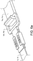
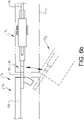
- the first connection member 7a may for example be arranged as a first hook structure 18a and a cooperating first opening structure 18b, as schematically shown in figures 1a-c and 6a-c .
- the first hook structure 18a is securely attached to the vehicle body structure 3 with suitable fastening means, such as for example screws, rivets or welds.
- the first opening structure 18b is securely attached to the first side safety structure 1a with suitable attachment means.
- the first hook structure 18a is engaging the first opening structure 18b for a secure attachment of the first side safety structure 1a to the vehicle body structure 3.
- the first opening structure 18b may be disengaged from the first hook structure 18a for an efficient opening of the first side door 4a.
- the first hook structure 18a is securely engaging the first opening structure 18b.
- the configuration of the first connection member 7a of the embodiments shown in figures 1a and 1b are illustrated more in detail in figures 6a-c , where the first hook structure 18a and the first opening structure 18b are illustrated.
- the structures are shown both in the closed door position P C , and in an open door position P O .
- the first connection member 7a of the embodiment shown in figure 1c may instead comprise two or more of first hook structures 18a, where the respective hook structures are cooperating with a corresponding first opening structure 18b.
- the second connection member 7b of the different embodiments may have a similar configuration as the first connection member 7a described above.
- the second connection member 7b may for example be arranged as a second hook structure 19a and a cooperating second opening structure 19b, as schematically shown in figures 1a-c .
- the second hook structure 19a is securely attached to the vehicle body structure 3 with suitable fastening means, such as for example screws, rivets or welds.
- the second opening structure 19b is securely attached to the second side safety structure 1b with suitable attachment means.
- the second hook structure 19a is engaging the second opening structure 19b for a secure attachment of the second side safety structure 1b to the vehicle body structure 3.
- the second opening structure 19b may be disengaged from the second hook structure 19a for an efficient opening of the second side door 4b, in a similar way as discussed in connection to figure 6b above.
- the second hook structure 19a is securely engaging the second opening structure 19b.
- the hook structures of the different embodiments are suitably made of a strong and rigid material and firmly connected to the respective structural elements, for a secure connection of the side safety structures.
- the opening structures are suitably made of a strong and rigid material for a secure connection to the respective hook structures. Suitable materials are for example metals, metallic materials, composite materials, or a combination of different materials.
- the first side safety structure 1a may be arranged as a beam structure in the first side door 4a, a flexible strap structure in the first side door 4a, or a membrane structure integrated in the first side door 4a, for example in connection to or integrated in an outer door panel 17 of the first side door 4a.
- the second side safety structure 1b may be arranged as a beam structure in the second side door 4b, a flexible strap structure in the second side door 4b, or a membrane structure integrated in the second side door 4b, for example in connection to or integrated in an outer door panel 17 of the second side door 4b.
- the first side safety structure 1a is suitably arranged as a thin flexible structural member, as schematically illustrated in for example figures 1a-c , 2a-c , 3a-b , and 4a-b , where the first side safety structure 1a is having a flat strap-like configuration.
- the first side safety structure 1a is having a thin membrane configuration.
- the first side safety structure 1a is for example made of a thin steel band, or alternatively from a thin structural member made of strong composite materials, polymers, or suitable fiber structures.
- the first side safety structure 1a is thin and lightweight in construction compared to traditional door beams for a compact and weight-saving side door construction.
- the first side safety structure 1a is suitably movably arranged in relation to the first side door 4a, and the first side safety structure 1a is thus allowed to move in relation to the first side door 4a in a vehicle impact event.
- the first side door 4a may for example be arranged with an internal channel-like structure, or similar recessed structure, for efficiently holding the first side safety structure 1a in a movable relationship to the first side door 4a. With this configuration, the first side safety structure 1a is acting like a strap preventing deformation of the first side door 4a in a vehicle impact event for protecting occupants of the vehicle V.
- the second side safety structure 1b is suitably arranged as a thin flexible structural member, as schematically illustrated in for example figures 1a-c , 2a-c , 3a-b , and 4a-b , where the second side safety structure 1b is having a flat strap-like configuration.
- the second side safety structure 1c is having a thin membrane configuration.
- the second side safety structure 1b is for example made of a thin steel band, or alternatively from a thin structural member made of strong composite materials, polymers, or suitable fiber structures.
- the second side safety structure 1b is thin and lightweight in construction compared to traditional door beams for a compact and weight-saving side door construction.
- the second side safety structure 1b is suitably movably arranged in relation to the second side door 4b, and the second side safety structure 1b is thus allowed to move in relation to the second side door 4b in a vehicle impact event.
- the second side door 4b may for example be arranged with an internal channel-like structure, or similar recessed structure, for efficiently holding the second side safety structure 1b in a movable relationship to the second side door 4b. With this configuration, the second side safety structure 1b is acting like a strap preventing deformation of the second side door 4b in a vehicle impact event for protecting occupants of the vehicle V.
- the side impact restraint protection system S comprises a first pair P1 of the first side safety structure 1a and the second side safety structure 1b, and a second pair P2 of the first side safety structure 1a and the second side safety structure 1b, arranged in the first side door 4a and the second side door 4b respectively.
- the side impact restraint protection system S comprises the first side safety structure 1a and the second side safety structure 1b arranged as membrane structures, as described above.
- This embodiment is similar in construction to the system illustrated in figure 1a , but the safety structures are having wider extensions.
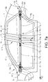
- the side impact restraint protection system S comprises a first door beam 8a arranged in the first side door 4a.
- the first door beam 8a is extending between a roof beam structure 9 and a sill structure 10 of the vehicle body structure 3 when the first side door 4a is arranged in the closed door position P C .
- the first side door 4a may be connected to the roof beam structure 9 and/or the sill structure 10 with suitable connection or locking devices for holding the door in the closed door position P C .
- the side impact restraint protection system S further comprises a second door beam 8b arranged in the second side door 4b.
- the second door beam 8b is extending between the roof beam structure 9 and the sill structure 10 of the vehicle body structure 3 when the second side door 4b is arranged in the closed door position P C .
- the second side door 4b may be connected to the roof beam structure 9 and/or the sill structure 10 with suitable connection or locking devices for holding the door in the closed door position P C .
- the first door beam 8a and the second door beam 8b are configured for replacing the B-pillar of the vehicle body structure 3, allowing a strong structural construction of the vehicle V with the common single door opening 5.
- the first door beam 8a is arranged in connection to a rear edge 11a of the first side door 4a
- the second door beam 8b is arranged in connection to a front edge 11b of the second side door 4b.
- the door beams may have any suitable configuration and construction for providing a strong structure for the side impact restraint protection system, and be made of any suitable materials, such as steel, other metals, metallic materials, composite materials, or a combination of different materials.
- the first side safety structure 1a with the connecting device 6 is in a lateral direction D LA of the vehicle V arranged outside of the first door beam 8a, and the second side safety structure 1b with the connecting device 6 is in the lateral direction D LA arranged outside of the second door beam 8b, for a safe construction of the side impact restraint protection system S.
- the first side safety structure 1a with the connecting device 6 is instead arranged inside of the first door beam 8a in the lateral direction D LA and the second side safety structure 1b with the connecting device 6 inside of the second door beam 8b in the lateral direction D LA .
- first safety structure 1a with the connecting device 6 is extending through the first door beam 8a
- second side safety structure 1b with the connecting device 6 is extending through the second door beam 8b.
- the door construction could alternatively be arranged with only one door beam arranged in the first side door 4a or the second side door 4b.
- the connecting device 6 comprises a first connector part 12a connected to the first side safety structure 1a via the safety release system S R .
- the side impact restraint protection system S in alternative non-illustrated embodiments may be arranged without the safety release system S R , and then the first connector part 12a instead is directly connected to the first side safety structure 1a.
- the illustrated connecting device 6 in figures 2a-b , 3a-b and 4a-b is having the configuration shown in figures 1a and 1b .
- the connecting device in figure 1c is having a similar construction but a wider extension.
- the connecting device 6 further comprises a second connector part 12b connected to the second side safety structure 1b.
- the first connector part 12a and the second connector part 12b are configured for releasably connecting the first side safety structure 1a and the second side safety structure 1b to each other.
- the connecting device 6 is configured for being arranged in a connected state S C where the first connector part 12a and the second connector part 12b are connected to each other, as shown in figure 2a and 2c , and a disconnected state S D where the first connector part 12a and the second connector part 12b are disconnected from each other, as shown in figure 2b .
- the connected state S C is used when the side doors are arranged in the closed door position P C for a secure connection between the first side safety structure 1a and the second side safety structure 1b.
- the disconnected state S D is allowing opening of the first side door 4a and/or the second side door 4b.
- a control unit may be used for controlling the states of the connecting device 6.
- the first connector part 12a comprises hook openings 14, and the second connector part 12b comprises a hook 13 with a plurality of hook elements.
- the hook 13 is in engagement with the hook openings 14 in the connected state S C , as shown in figure 2a , and configured for being disengaged from the hook openings 14 in the disconnected state S D , as shown in figure 2b .
- the first side safety structure 1a and the second side safety structure are securely connected to each other through the interaction between the hook 13 and the hook openings 14.
- the hook 13 is configured for pivoting between a connected position P CO in the connected state S C and a disconnected position P DI in the disconnected state S D , as shown in figures 2a-b , and the hook 13 may for example be pivotably connected to the second connector part 12b via a hinged member, a pivot axis or other suitable pivoting mechanism.
- the pivoting movement between the connected position P CO and the disconnected position P DI may be achieved with for example a suitable actuating mechanism or an actuating mechanism together with a spring arrangement.
- a suitable actuator is for example an electric motor, a solenoid-type actuator, or other suitable linear or rotary actuators.
- the first connector part 12a may instead comprise the hook 13 and the second connector part 12b the hook openings 14.
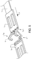
- FIG. 5 An alternative embodiment of the connecting device 6 is schematically shown in figure 5 .
- the hook 13 is instead configured with oppositely arranged hook elements for a firm connection between the hook 13 and the corresponding hook openings 14.
- the oppositely arranged hook elements are configured for moving in different directions between the connected position P CO and the disconnected position P DI .
- the hook 13 comprises three hook elements.
- the hook 13 may alternatively comprise only one single hook element, two hook elements, or more than three hook elements if suitable, depending on the construction and design of the connecting device.
- a connecting device 6 with a plurality of hook elements are schematically indicated in figure 1c .
- the connecting device 6 may comprise a corresponding number of hook openings 14 to match the configuration of the hook 13.
- the side impact restraint protection system S comprises a first tensioning unit 15a connected to the first side safety structure 1a, where the first tensioning unit 15a is replacing the first opening structure 18b described above.
- the first tensioning unit 15a is configured for irreversibly tensioning the first side safety structure 1a and the second safety structure 1b in relation to the vehicle body structure 3 in a vehicle impact event for minimizing play between the vehicle body structure 3, the first side door 4a, and the second side door 4b.
- the first tensioning unit 15a may comprise a first pyrotechnic tensioning device 16a configured for tensioning the first side safety structure 1a and the second safety structure 1b in relation to the vehicle body structure 3.
- the first tensioning unit 15a may have any suitable configuration, and it should be understood that the first tensioning unit 15a could have a design and construction similar to tensioning devices used in seat belt restraint systems, such as for example a seat belt pyrotechnic pre-tensioner. Other tensioning devices than pyrotechnical may also be used in other embodiments.
- the first tensioning unit 15a is forming part of the first connection member 7a instead of the first opening structure 18b.
- the first tensioning unit 15a is securely attached to the first side safety structure 1a with suitable attachment means.
- the first tensioning unit 15a is arranged with a first part 20a comprising an opening 21, where the opening 21 is cooperating with the first hook structure 18a in a similar way as the opening structure 18b described above in connection to figures 1a-c and 6a-c .
- the first hook structure 18a is engaging the opening 21 for a secure attachment of the first side safety structure 1a to the vehicle body structure 3.
- the opening 21 may be disengaged from the first hook structure 18a for an efficient opening of the first side door 4a.
- the first hook structure 18a is securely engaging the opening 21.
- the first tensioning unit 15a is configured for being irreversibly displaced from an untensioned state S U to a tensioned state S T .
- the states are suitably controlled by the control unit.
- the untensioned state S U is schematically shown in figure 7b and the tensioned state S T in figure 7c .
- the first tensioning unit 15a is displaced from the untensioned state S U to the tensioned state S T , the first side safety structure 1a together with the second side safety structure 1b is pulled in a direction towards the first hook structure 18a.
- the pulling action is established with the first pyrotechnic tensioning device 16a.
- the first tensioning unit 15a comprises the first part 20a in which the opening 21 is arranged, and a second part 20b to which the first side safety structure 1a is attached.
- the first part 20a and the second part 20b are slidably arranged in relation to each other.
- the first pyrotechnic tensioning device 16a comprises a main portion 22 that is connected to the second part 20b, and to a wire 23 that is extending from the main portion 22 to the first part 20a.
- the wire 23 is securely attached to the first part 20a.
- the first pyrotechnic tensioning device 16a Upon displacement of the first tensioning unit 15a from the untensioned state S U to the tensioned state S T , the first pyrotechnic tensioning device 16a is exerting a pulling action onto the wire 23 for displacing the first part 20a and the second part 20b in relation to each other from the untensioned state S U , shown in figure 7b , to the tensioned state S T , shown in figure 7c .
- the main portion 22 may comprise barbs or similar devices for holding the wire 23 in a tensioned position in the tensioned state S T .
- the first tensioning unit 15a is irreversibly tensioning the first side safety structure 1a and the second safety structure 1b in relation to the vehicle body structure 3 in a vehicle impact event for minimizing play between the vehicle body structure 3, the first side door 4a, and the second side door 4b.
- the side impact restraint protection system S may instead of or in addition to the first tensioning unit 15a comprise a second tensioning unit 15b connected to the second side safety structure 1b, replacing the second opening structure 19b described above.
- the side impact restraint protection system S comprises both the first tensioning unit 15a and the second tensioning unit 15b.
- the side impact restraint protection system S may in non-illustrated embodiments instead be arranged with only the first tensioning unit 15a or the second tensioning unit 15b.
- the second tensioning unit 15b is forming part of the second connection member 7b instead of the second opening structure 19b.
- the second tensioning unit 15b may have the same configuration and function as the first tensioning unit 15a, as illustrated in figures 7b-c .
- the second tensioning unit 15b is arranged with an opening 21 that is cooperating with the second hook structure 19a, in a similar way as the second opening structure 19b described above in connection to figures 1a-c .
- the second tensioning unit 15b is configured for irreversibly tensioning the first side safety structure 1a and the second safety structure 1b in relation to the vehicle body structure 3 in a vehicle impact event for minimizing play between the vehicle body structure 3, the first side door 4a, and the second side door 4b.
- the second tensioning unit 15b may comprises a second pyrotechnic tensioning device 16b configured for tensioning the first side safety structure 1a and the second safety structure 1b in relation to the vehicle body structure 3.
- the second tensioning unit 15b may have any suitable configuration, and it should be understood that the second tensioning unit 15b could have a design and construction similar to tensioning devices used in seat belt restraint systems, such as for example a seat belt pyrotechnic pre-tensioner. Other tensioning devices than pyrotechnical may also be used in other embodiments.
- the second tensioning unit 15b is configured for being irreversibly displaced from an untensioned state S U to a tensioned state S T .
- the states are suitably controlled by the control unit.
- the untensioned state S U is schematically shown in figure 7b and the tensioned state S T in figure 7c .
- the second tensioning unit 15b is displaced from the untensioned state S U to the tensioned state S T , the second side safety structure 1b together with the first side safety structure 1b is pulled in a direction towards the second hook structure 19a.
- the first side safety structure 1a is connected to the connecting device 6 via the safety release system S R .
- the safety release system S R is arranged between the first side safety structure 1a and the connecting device 6, and the connecting device 6 is configured for releasably attaching the first side safety structure 1a to the second side safety structure 1b.
- the safety release system S R being part of the side impact restraint protection system S for a vehicle V is schematically illustrated.
- the safety release system S R is arranged for releasing the connection between the first side safety structure 1a and the connecting device 6 of the side impact restraint protection system S after a vehicle impact event, and the safety release system S R is an important safety feature of the side impact restraint protection system S.
- the safety release system S R is thus configured for enabling opening of the first side door 4a and/or the second vehicle door 4b after the vehicle impact event.
- the first side safety structure 1a is arranged in connection to the first side door 4a.
- the safety release system S R comprises a releasing mechanism 100 and a releasing member 101 detachable from each other.
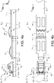
- the safety release system S R is configured for being arranged in a first state S1 where the releasing mechanism 100 and the releasing member 101 are connected to each other, as shown in figures 2a-b and 3a-b , and a second state S2 where the releasing mechanism 100 and the releasing member 101 are disconnected from each other, as shown in figures 2c and 4a-b .
- the safety release system S R is in the illustrated embodiments arranged between the first side safety structure 1a and the connecting device 6, and the safety release system S R is configured for releasing the connection between the first side safety structure 1a and the connecting device 6 of the side impact restraint protection system S after the vehicle impact event. After such an impact event, it may due to vehicle deformation be impossible to disconnect the connecting device 6 for opening the vehicle side door or side doors, and then the safety release system S R is instead used for disconnecting the first side door 4a and/or the second side door 4b as shown in the illustrated embodiments.
- the safety release system S R is thus arranged for releasing the connection between the first side safety structure 1a and the connecting device 6 after the vehicle impact event.
- the first side safety structure 1a is arranged in connection to the first side door 4a of the vehicle V, and the safety release system S R is configured for enabling opening of the first side door 4a and/or the second side door 4b, after the vehicle impact event.
- the safety release system S R is instead arranged between the second side safety structure 1b and the connecting device 6, and the safety release system S R is configured for releasing the connection between the second side safety structure 1b and the connecting device 6 of the side impact restraint protection system S after the vehicle impact event.
- the safety release system S R comprises the releasing mechanism 100 and the releasing member 101 detachably arranged in relation to each other.
- the releasing mechanism 100 is attached to the first side safety structure 1a, and the releasing member 101 is connected to the connecting device 6.
- the safety release system S R is configured for being arranged in a first state S1 where the releasing mechanism 100 and the releasing member 101 are connected to each other, as shown in figures 2a and 3a-b , and a second state S2 where the releasing mechanism 100 and the releasing member 101 are disconnected from each other, as shown in figures 2c and 4a-b .
- the releasing mechanism 100 comprises a hook member 102 and the releasing member 101 comprises a hook receiving opening 101a.
- the hook member 102 is configured for being engaged with the hook receiving opening 101a in the first state S1 and configured for being disengaged from the hook receiving opening 101a in the second state S2.
- the hook member 102 is configured for pivoting from an engaged position P E in the first state S1, as illustrated in figures 2a and 3a-b , to a disengaged position P D in the second state S2, as illustrated in figures 2c and 4a-b .
- the hook member 102 is pivotally displaceable by one or more springs 106.
- the hook member 102 is pre-tensioned with the springs 106 in the first state S1, and the springs 106 are displacing the hook member 102 from the engaged position P E to the disengaged position P D in the second state S2.
- the springs 106 may have any suitable configuration, such as for example torsion springs or other suitable spring mechanisms.
- the releasing mechanism 100 further comprises a safety pin 103, which is preventing displacement of the hook member 102 from the engaged position P E to the disengaged position P D in the first state S1. In the second state S2, the safety pin 103 is allowing displacement of the hook member 102 from the engaged position P E to the disengaged position P D .
- the releasing mechanism 100 comprises a first wall structure 104a and a second wall structure 104b, as schematically illustrated in figures 2a-c , 3a-b , and 4a-b .
- the hook member 102 is pivotally connected to and extending between the first wall structure 104a and the second wall structure 104b, and the hook member 102 is arranged to pivot around a hook rotational axis R H when the safety release system S R is displaced from the first state S1 to the second state S2.
- the pivoting arrangement of the hook member 102 may for example be accomplished with a shaft extending between the first wall structure 104a and the second wall structure 104b, where the hook member 102 is rotatably attached to the shaft, or alternatively where the shaft is rotatably arranged in relation to the wall structures, allowing a pivoting movement of the hook member 102.
- the hook member 102 In the first state S1, the hook member 102 is in engagement with the hook receiving opening 101a in the engaged position P E , as shown in figures 2a and 3a-b .
- the hook member is disengaged from the hook receiving opening 101a in the disengaged position P D , as shown in figures 2c and 4a-b .
- the first wall structure 104a comprises a first safety pin track 105a and the second wall structure 104b comprises a second safety pin track 105b.
- the safety pin 103 is movably connected to and extending between the first wall structure 104a and the second wall structure 104b.
- the safety pin 103 is configured to move in relation to the first wall structure 104a in the first safety pin track 105a and in relation to the second wall structure 104b in the second safety pin track 105b from a locked position P L in the first state S1 where the safety pin 103 is blocking movement of the hook member 102, as shown in figures 2a and 3a-b , to an unlocked position P U in the second state S2 where the safety pin 103 is allowing movement of the hook member 102 from the engaged position P E to the disengaged position P D , as shown in figures 2c and 3a-b .
- the releasing mechanism comprises an actuating unit 107 connected to the safety pin 103, as schematically indicated in figure 2a .
- the actuating unit 107 is configured for displacing the safety pin 103 from the locked position P L in the first state S1 to the unlocked position P U in the second state S2.
- the actuating unit 107 may for example be a mechanical actuator, where a wire structure in one end is connected to the safety pin 103 and in the other end to an actuating handle. When moving the actuating handle, the safety pin 103 is displaced from the locked position P L to the unlocked position P U . In this way, the actuating handle is used for changing the state of the safety release system S R , from the first state S1 to the second state S2.
- the actuating handle When moving the actuating handle, the safety pin 103 is moved from the locked position P L to the unlocked position P U , and in the unlocked position P U the hook member 102 is displaced from the engaged position P E to the disengaged position P D by the springs 106.
- the actuating handle may be arranged on the vehicle V for easy access from inside the vehicle and outside the vehicle.
- the actuating unit may alternatively comprise two actuating handles connected to the safety pin 103, one arranged inside the passenger compartment of the vehicle V and one in connection to an external surface of the vehicle V.
- the hook member 102 may be pivotally displaceable by an electric motor, where the electric motor upon activation by the control unit is configured for displacing the hook member 102 from the engaged position P E in the first state S1 to the disengaged position P D in the second state S2.
- the actuating unit 107 may alternatively be arranged as an electric actuator, for displacing the safety pin 103, upon initiation by a user via for example an electric switch arrangement connected to the actuating unit 107 or remotely controlled via a mobile phone app.
- the control unit is suitably connected to the electric actuator for controlling the system.
- the electric actuator may for example be a solenoid or other type of linear or rotary actuator used for displacing the safety pin 103 from the locked position P L to the unlocked position P U . If using an electric motor for displacing the hook member 102, the safety pin 103 may be omitted if suitable, and the electric motor can be activated upon initiation by a user via for example an electric switch arrangement connected to the electric motor.
- the safety release system S R is operated after a vehicle impact event when the connecting device 6 is damaged or prevented from being displaced from the connected position P CO to the disconnected position P DI , for example if a deformation of the vehicle body structure 3 and/or of one or more side doors prevents normal operation of the connecting device 6 for opening the vehicle side doors. If a vehicle impact event has occurred, and the side doors of the vehicle V cannot be opened or only partly opened due to malfunctioning or damaged components, the safety release system S R may be operated by an occupant or user of the vehicle V or by other persons in connection to the vehicle V, such as for example rescue personnel.
- the control unit may be used for detecting malfunctioning or damaged components, or alternatively manually detected by a person trying to open the side doors with the door opening mechanism.
- the safety release system S R is arranged in a second state S2 after the vehicle impact event.
- the releasing mechanism 100 and the releasing member 101 are disconnected from each other for releasing the connection between the first side safety structure 1a and the connecting device 6, which is enabling opening of the first side door 4a and the second side door 4b.
- the safety pin 103 is moved from the locked position P L to the unlocked position P U in the second state S2, allowing movement of the hook member 102 from the engaged position P E to the disengaged position P D .
- the safety pin 103 is as described above displaced with the actuating unit 107 from the locked position P L to the unlocked position P U .
- the hook member 102 After movement of the safety pin 103 to the unlocked position P U , the hook member 102 is released from the hook receiving opening 101a in the second state S2.
- the hook member 102 is pivoted from the engaged position P E in the first state S1 to the disengaged position P D in the second state S2, where the one or more springs 106 are displacing the hook member 102 from the engaged position P E to the disengaged position P D in the second state S2, pivoting the hook member 102 from an engaged position P E in the first state S1 to a disengaged position P D in the second state S2.
- the releasing member 101 In the disengaged position, the releasing member 101 is allowed to slide away from the hook member 102 when opening the first side door 4a and/or the second side door 4b.
- the electric motor is displacing the hook member 102 from the engaged position P E to the disengaged position P D in the second state S2, as described above.
- a non-transitory computer-readable storage medium storing one or more programs configured to be executed by one or more processors of the control unit, the one or more programs comprising instructions for performing the method according to any one of the above-discussed embodiments.
- the processor may be connected to one or more communication interfaces and/or sensor interfaces for receiving and/transmitting data with external entities such as e.g. sensors arranged on the vehicle surface, an off-site server, or a cloud-based server.
- the processor or processors associated with the side impact restraint protection system S may be or include any number of hardware components for conducting data or signal processing or for executing computer code stored in memory.
- the system may have an associated memory, and the memory may be one or more devices for storing data and/or computer code for completing or facilitating the various methods described in the present description.
- the memory may include volatile memory or non-volatile memory.
- the memory may include database components, object code components, script components, or any other type of information structure for supporting the various activities of the present description.
- any distributed or local memory device may be utilized with the systems and methods of this description.
- the memory is communicably connected to the processor (e.g., via a circuit or any other wired, wireless, or network connection) and includes computer code for executing one or more processes described herein.
Landscapes
- Engineering & Computer Science (AREA)
- Mechanical Engineering (AREA)
- Chemical & Material Sciences (AREA)
- Combustion & Propulsion (AREA)
- Transportation (AREA)
- Body Structure For Vehicles (AREA)
Abstract
Description
- The present disclosure relates to a side impact restraint protection system for a vehicle. The side impact restraint protection system comprises a first side safety structure, a second side safety structure, a first structural element of a vehicle body structure of the vehicle, and a second structural element of the vehicle body structure. The first side safety structure is arranged in connection to a first side door of the vehicle and the second side safety structure is arranged in connection to a second side door of the vehicle.
- Side impact systems are commonly used in vehicle constructions. Often door beam constructions arranged in the side doors of the vehicle are used to protect the occupants of the vehicle in a side impact event. The door beams are sometimes configured to cooperate with the A-pillar, B-pillar, and the C-pillar of the vehicle to capture impact energy efficiently. Door beams are due to strength requirements heavy in construction and commonly made of steel. Despite heavy and rigid door constructions, the side doors are not contributing to the strength and stiffness of the vehicle body structure as such, because there is a play with seal members arranged between the doors and the vehicle body structure. The doors are thus adding weight to the vehicle construction without strengthening the vehicle body structure, which is unfavourable from a crash safety and fuel or energy consumption perspective. Further, many of today's side impact systems will not meet future legal requirements of crash strength, and therefore stronger and heavier door beam constructions are needed, as well as stiffer, stronger and heavier car body constructions. The trend with vehicle body constructions without B-pillars is creating further needs for even stronger and heavier vehicle door constructions.
- There is thus a need for an improved side impact protection system, which will meet future strength and safety requirements, where the system is lightweight in construction and suitable for different vehicle constructions, as vehicle constructions without B-pillars, where the system further is enabling and simplifying opening of the side doors after a side impact event.
- An object of the present disclosure is to provide a side impact restraint protection system where the previously mentioned problems are avoided. This object is at least partly achieved by the features of the independent claim. The dependent claims contain further developments of the side impact restraint protection system.
- The disclosure concerns a side impact restraint protection system for a vehicle, comprising a first side safety structure, a second side safety structure, a first structural element of a vehicle body structure of the vehicle, and a second structural element of the vehicle body structure. The first side safety structure is arranged in connection to a first side door of the vehicle and the second side safety structure is arranged in connection to a second side door of the vehicle. The first side door and the second side door are arranged to cover a common single door opening of the vehicle body structure in a closed door position. The first structural element is arranged in a position in front of the door opening in a longitudinal direction of the vehicle, and the second structural element is arranged in a position behind the door opening in the longitudinal direction. In the closed door position the first side safety structure and the second side safety structure are configured to be releasably connected to each other via a connecting device, the first side safety structure is configured to be connected to the first structural element via a first connection member, and the second side safety structure is configured to be connected to the second structural element via a second connection member.
- Advantages with these features are that the construction is providing a strong and safe design of the side impact restraint protection system suitable for meeting future legal requirements for crash strength, where the system is capturing impact energy efficiently. The side impact restraint protection system with this design can be made lightweight in construction and suitable for different vehicle constructions, as vehicle constructions without B-pillars. With the system, the door can be made more lightweight in construction without traditional heavy door beams. The system is with the releasable connection via the connecting device further enabling and simplifying opening of the side doors after a side impact event.
- According to an aspect of the disclosure, the system comprises a first door beam arranged in the first side door, and/or a second door beam arranged in the second side door. The first door beam is extending between a roof beam structure and a sill structure of the vehicle body structure when the first side door is arranged in the closed door position. The second door beam is extending between the roof beam structure and the sill structure of the vehicle body structure when the second side door is arranged in the closed door position. The respective side doors are suitably connected to the roof beam structure and/or the sill structure with connection or locking devices for efficiently holding the door in the closed door position.
- According to another aspect of the disclosure, the first door beam is configured for replacing a B-pillar of the vehicle body structure, and/or the second door beam is configured for replacing a B-pillar of the vehicle body structure. The door beams are designed to absorb impact load and for cooperating with the side safety structures and the car body structure for efficiently protecting occupants of the vehicle.
- According to an aspect of the disclosure, the first side door is a front vehicle side door and the first door beam is arranged in connection to a rear edge of the first side door, and/or the second side door is a rear vehicle side door and the second door beam is arranged in connection to a front edge of the second side door. With this arrangement of the door beams, a strong and robust system configuration is achieved for preventing major deformations of the side doors in a vehicle impact event.
- According to another aspect of the disclosure, the first side safety structure is in a lateral direction of the vehicle arranged outside of the first door beam, and/or the second side safety structure is in a lateral direction of the vehicle arranged outside of the second door beam. In this way, the door beams can absorb energy in a vehicle impact event and the impact forces can be efficiently distributed via the side safety structures to the vehicle body structure.
- According to a further aspect of the disclosure, the connecting device comprises a first connector part connected to the first side safety structure and a second connector part connected to the second side safety structure. The first connector part and the second connector part are configured for releasably connecting the first side safety structure and the second side safety structure to each other. The connecting device is configured for being arranged in a connected state where the first connector part and the second connector part are connected to each other and a disconnected state where the first connector part and the second connector part are disconnected from each other. The connected state is used when the side doors are arranged in the closed door position for a secure connection between the first side safety structure and the second side safety structure. The disconnected state is allowing opening of the first side door and/or the second side door.
- According to an aspect of the disclosure, the first connector part or the second connector part comprises a hook and the other of the first connector part or the second connector part comprises one or more hook openings. The hook is configured for being engaged with the one or more hook openings in the connected state and configured for being disengaged from the one or more hook openings in the disconnected state. The cooperating hook and hook openings are providing a simple and secure connection between the connector parts.
- According to another aspect of the disclosure, the hook is configured for pivoting between a connected position in the connected state and a disconnected position in the disconnected state. The pivoting arrangement of the hook is efficiently displacing the system between the connected and disconnected states.
- According to a further aspect of the disclosure, the system comprises a first tensioning unit connected to the first side safety structure, and/or the system comprises a second tensioning unit connected to the second side safety structure. The first tensioning unit is configured for irreversibly tensioning the first side safety structure and the second safety structure in relation to the vehicle body structure in a vehicle impact event for minimizing play between the vehicle body structure, the first side door, and the second side door. The second tensioning unit is configured for irreversibly tensioning the first side safety structure and the second safety structure in relation to the vehicle body structure in a vehicle impact event for minimizing play between the vehicle body structure, the first side door, and the second side door.
- According to an aspect of the disclosure, the first tensioning unit comprises a first pyrotechnic tensioning device configured for tensioning the first side safety structure and the second safety structure in relation to the vehicle body structure, and/or the second tensioning unit comprises a second pyrotechnic tensioning device configured for tensioning the first side safety structure and the second safety structure in relation to the vehicle body structure. The pyrotechnic tensioning is providing an efficient and reliable tensioning of the system in a vehicle impact event.
- According to another aspect of the disclosure, the first side safety structure is in a first end releasably connected to the first structural element via the first connection member, and in a second end connected to the connecting device. The second side safety structure is in a first end connected to the connecting device, and in a second end releasably connected to the second structural element via the second connection member. The connections are providing an efficient coupling between the system parts, and also allowing opening of the doors.
- According to a further aspect of the disclosure, the first side safety structure is connected to the connecting device via a safety release system. The safety release system is arranged between the first side safety structure and the connecting device, and the safety release system is configured for releasing a connection between the first side safety structure and the connecting device after a vehicle impact event. With the safety release system, opening of the side doors after a side impact event is enabled and simplified.
- According to an aspect of the disclosure, the safety release system comprises a releasing mechanism and a releasing member detachably arranged in relation to each other. The safety release system is configured for being arranged in a first state where the releasing mechanism and the releasing member are connected to each other and a second state where the releasing mechanism and the releasing member are disconnected from each other. Through the detachable arrangement of the releasing mechanism and the releasing member from each other, the side doors can be opened without using the connecting device. By changing the safety release system from the first state where the releasing mechanism and the releasing member are connected, to the second state where the releasing mechanism and the releasing member are disconnected from each other, opening of the side doors is enabled.
- According to another aspect of the disclosure, the releasing mechanism comprises a hook member and the releasing member comprises a hook receiving opening. The hook member is configured for being engaged with the hook receiving opening in the first state and configured for being disengaged from the hook receiving opening in the second state. The hook member is configured for pivoting from an engaged position in the first state to a disengaged position in the second state. The hook member and the hook receiving opening are efficiently cooperating for disengaging the connection of the releasing mechanism after the vehicle impact event. The pivoting function is suitable for a secure disengagement of the hook member from the hook receiving opening.
- According to a further aspect of the disclosure, the releasing mechanism comprises a safety pin configured for preventing displacement of the hook member from the engaged position to the disengaged position in the first state. The safety pin is configured for allowing displacement of the hook member from the engaged position to the disengaged position in the second state. The safety pin is securing unintended or unwanted displacement of the hook member from the engaged position to the disengaged position.
- According to an aspect of the disclosure, the releasing mechanism comprises an actuating unit connected to the safety pin. The actuating unit is configured for displacing the safety pin from a locked position to an unlocked position in the second state. The actuating unit is providing an efficient way to move the locking pin to the unlocked position, which in turn is allowing the movement of the hook member.
- According to another aspect of the disclosure, the first side safety structure is movably arranged in relation to the first side door, and the second side safety structure is movably arranged in relation to the second side door. The movably arranged side safety structures are allowing an efficient capturing of impact energy, and is preventing major deformations of the side doors in a vehicle impact event for protecting occupants of the vehicle.
- According to a further aspect of the disclosure, the first structural element is arranged forward of the door opening in a longitudinal direction of the vehicle, and the second structural element is arranged rearward of the door opening in the longitudinal direction.
- According to an aspect of the disclosure, the first structural element is an A-pillar of the vehicle body structure, and that the second structural element is a C-pillar of the vehicle body structure. The connections to the A-pillar and the C-pillar respectively are providing a strong and robust construction of the side impact restraint protection system.
- According to another aspect of the disclosure, the first side safety structure is arranged as a beam structure in the first side door, a flexible strap structure in the first side door, or a membrane structure integrated in an outer door panel of the first side door. The second side safety structure is arranged as a beam structure in the second side door, a flexible strap structure in the second side door, or a membrane structure integrated in an outer door panel of the second side door. There are thus different possibilities for designing the side safety structures, and the construction may vary with the design of the vehicle.
- According to a further aspect of the disclosure, the system comprises a first pair of the first side safety structure and the second side safety structure, and a second pair of the first side safety structure and the second side safety structure, arranged in the first side door and the second side door respectively. The pair of side safety structures is used for further increasing the safety of the system for preventing major deformations of the side doors in a vehicle impact event.
- The disclosure will be described in detail in the following, with reference to the attached drawings, in which
- Fig. 1a-c
- show schematically, in side views, embodiments of a side impact restraint protection system, according to the disclosure,
- Fig. 2a-c
- show schematically, in perspective views, different operating positions of a connecting device and a safety release system of the side impact restraint protection system, according to the disclosure,
- Fig. 3a-b
- show schematically, in a view from above and in a side view, the connecting device in a connected position, and the safety release system in a locked and engaged position, according to the disclosure,
- Fig. 4a-b
- show schematically, in a view from above and in a side view, the connecting device in the connected position, and the safety release system in an unlocked and disengaged position, according to the disclosure,
- Fig. 5
- shows schematically in a perspective view, an alternative embodiment of the connecting device according to the disclosure,
- Fig. 6a-c
- show schematically, in a perspective view, a view from above, and in a side view, a connection member of the side impact restraint protection system, and
- Fig 7a-c
- show schematically, in a perspective view and in side views, a tensioning device, according to the disclosure.
- Various aspects of the disclosure will hereinafter be described in conjunction with the appended drawings to illustrate and not to limit the disclosure, wherein like designations denote like elements, and variations of the described aspects are not restricted to the specifically shown embodiments, but are applicable on other variations of the disclosure.
- Those skilled in the art will appreciate that the steps, services and functions explained herein may be implemented using individual hardware circuitry, using software functioning in conjunction with a programmed microprocessor or general purpose computer, using one or more Application Specific Integrated Circuits (ASICs) and/or using one or more Digital Signal Processors (DSPs). It will also be appreciated that when the present disclosure is described in terms of a method, it may also be embodied in one or more processors and one or more memories coupled to the one or more processors, wherein the one or more memories store one or more programs that perform the steps, services and functions disclosed herein when executed by the one or more processors.
-
Figure 1a-c schematically show embodiments of a side impact restraint protection system S for a vehicle V. The side impact restraint protection system S comprises a firstside safety structure 1a, a secondside safety structure 1b, a firststructural element 2a of avehicle body structure 3 of the vehicle V, and a secondstructural element 2b of thevehicle body structure 3. The firstside safety structure 1a is arranged in connection to afirst side door 4a of the vehicle V, and the secondside safety structure 1b is arranged in connection to asecond side door 4b of the vehicle V. Thefirst side door 4a and thesecond side door 4b are arranged to cover a commonsingle door opening 5 of thevehicle body structure 3 in a closed door position Pc. The firststructural element 2a is arranged in a position in front of thedoor opening 5 in a longitudinal direction DLO of the vehicle V, and the secondstructural element 2b arranged in a position behind thedoor opening 5 in the longitudinal direction DLO. In the closed door position PC, the firstside safety structure 1a and the secondside safety structure 1b are configured to be releasably connected to each other via a connectingdevice 6. The firstside safety structure 1a is configured to be connected to the firststructural element 2a via afirst connection member 7a, and the secondside safety structure 1b is configured to be connected to the secondstructural element 2b via asecond connection member 7b. - As schematically illustrated in
figures 1a-c , the firstside safety structure 1a and the secondside safety structure 1b are when connected to each other forming a structure that is extending in the respective side doors from the firststructural element 2a of thevehicle body structure 3 to the secondstructural element 2b of thevehicle body structure 3. In the embodiments illustrated infigures 1a-c , the side safety structures are together forming a strap-like or membrane-like safety member extending over thedoor opening 5 for protecting the occupants of the vehicle V in a side impact event. Through the secure connection to the firststructural element 2a and the secondstructural element 2b, the connected firstside safety structure 1a and the secondside safety structure 1b are cooperating to absorb crash energy in a vehicle impact event. The crash energy is in this way efficiently transferred from the side doors during the vehicle impact event to the respective side safety structures and thevehicle body structure 3 through the secure connection between the firststructural element 2a, the firstside safety structure 1a, the secondside safety structure 1b, and the secondstructural element 2b. In this way, the side doors are cooperating with thecar body structure 3 for absorbing energy. - The vehicle V is suitably configured with a control unit for controlling the different functions of the side impact restraint protection system S. The control unit may for example be connected to sensors for detecting the vehicle impact event and further connected to parts of the system for determining the functionality and status of components involved. Suitable sensors may be used for the detections and determinations needed. Furthermore, the control unit may also be connected to sensors configured to detect and track vehicles or objects surrounding the vehicle V for predicting the vehicle impact event.
- The
first side door 4a and thesecond side door 4b are in the illustrated embodiments infigures 1a-c arranged to cover a commonsingle door opening 5 of thevehicle body structure 3 in a closed door position Pc. As shown infigures 1a-c , thefirst side door 4a is a front vehicle side door and thesecond side door 4b is a rear vehicle side door. The commonsingle door opening 5 is arranged without a B-pillar, and the side doors can be opened and closed in relation to the door opening 5 of thevehicle body structure 3 by suitable opening and closing mechanisms. The firststructural element 2a is thus arranged forward of thedoor opening 5 in a longitudinal direction DLO of the vehicle V. The firststructural element 2a may be any suitable part of thevehicle body structure 3. In the illustrated embodiments infigures 1a-c , the firststructural element 2a is the A-pillar, or the A-pillar extension, of thevehicle body structure 3. The secondstructural element 2b is arranged rearward of thedoor opening 5 in the longitudinal direction DLO of the vehicle V. The secondstructural element 2b may be any suitable part of thevehicle body structure 3. In the illustrated embodiments, the secondstructural element 2b is the C-pillar, or the C-pillar extension, of thevehicle body structure 3. As shown infigures 1a-c , thefirst connection member 7a is arranged in connection to the A-pillar of thevehicle body structure 3, and thesecond connection member 7b is arranged in connection to the C-pillar of thevehicle body structure 3. - In the closed door position PC, as illustrated in
figures 1a-c , the firstside safety structure 1a and the secondside safety structure 1b are releasably connected to each other via the connectingdevice 6. The firstside safety structure 1a is connected to the firststructural element 2a of thevehicle body structure 3 via thefirst connection member 7a, and the secondside safety structure 1b is connected to the secondstructural element 2b of thevehicle body structure 3 via thesecond connection member 7b. - As shown in
figures 1a-c , the firstside safety structure 1a is in a first end A1 releasably connected to the firststructural element 2a via thefirst connection member 7a, and in a second end A2 connected to the connectingdevice 6 via a safety release system SR. The side impact restraint protection system S in the illustrated embodiments thus comprises the safety release system SR. The secondside safety structure 1b is in a first end B1 connected to the connectingdevice 6 and in a second end B2 releasably connected to the secondstructural element 2b via thesecond connection member 7b. - The
first connection member 7a may for example be arranged as afirst hook structure 18a and a cooperatingfirst opening structure 18b, as schematically shown infigures 1a-c and6a-c . Thefirst hook structure 18a is securely attached to thevehicle body structure 3 with suitable fastening means, such as for example screws, rivets or welds. Thefirst opening structure 18b is securely attached to the firstside safety structure 1a with suitable attachment means. When thefirst side door 4a is in the closed door position Pc, thefirst hook structure 18a is engaging thefirst opening structure 18b for a secure attachment of the firstside safety structure 1a to thevehicle body structure 3. When thefirst side door 4a is opened, as indicated with dotted lines infigure 6b , thefirst opening structure 18b may be disengaged from thefirst hook structure 18a for an efficient opening of thefirst side door 4a. When thefirst side door 4a is moved from an open door position PO back to the closed door position PC, thefirst hook structure 18a is securely engaging thefirst opening structure 18b. The configuration of thefirst connection member 7a of the embodiments shown infigures 1a and1b are illustrated more in detail infigures 6a-c , where thefirst hook structure 18a and thefirst opening structure 18b are illustrated. Infigure 6b , the structures are shown both in the closed door position PC, and in an open door position PO. Thefirst connection member 7a of the embodiment shown infigure 1c may instead comprise two or more offirst hook structures 18a, where the respective hook structures are cooperating with a correspondingfirst opening structure 18b. - The
second connection member 7b of the different embodiments may have a similar configuration as thefirst connection member 7a described above. Thesecond connection member 7b may for example be arranged as asecond hook structure 19a and a cooperatingsecond opening structure 19b, as schematically shown infigures 1a-c . Thesecond hook structure 19a is securely attached to thevehicle body structure 3 with suitable fastening means, such as for example screws, rivets or welds. Thesecond opening structure 19b is securely attached to the secondside safety structure 1b with suitable attachment means. When thesecond side door 4b is in the closed door position PC, thesecond hook structure 19a is engaging thesecond opening structure 19b for a secure attachment of the secondside safety structure 1b to thevehicle body structure 3. When thesecond side door 4b is opened, thesecond opening structure 19b may be disengaged from thesecond hook structure 19a for an efficient opening of thesecond side door 4b, in a similar way as discussed in connection tofigure 6b above. When thesecond side door 4b is moved from an open door position back to the closed door position PC, thesecond hook structure 19a is securely engaging thesecond opening structure 19b. - The hook structures of the different embodiments are suitably made of a strong and rigid material and firmly connected to the respective structural elements, for a secure connection of the side safety structures. The opening structures are suitably made of a strong and rigid material for a secure connection to the respective hook structures. Suitable materials are for example metals, metallic materials, composite materials, or a combination of different materials.
- The first
side safety structure 1a may be arranged as a beam structure in thefirst side door 4a, a flexible strap structure in thefirst side door 4a, or a membrane structure integrated in thefirst side door 4a, for example in connection to or integrated in anouter door panel 17 of thefirst side door 4a. The secondside safety structure 1b may be arranged as a beam structure in thesecond side door 4b, a flexible strap structure in thesecond side door 4b, or a membrane structure integrated in thesecond side door 4b, for example in connection to or integrated in anouter door panel 17 of thesecond side door 4b. - The first
side safety structure 1a is suitably arranged as a thin flexible structural member, as schematically illustrated in for examplefigures 1a-c ,2a-c ,3a-b , and4a-b , where the firstside safety structure 1a is having a flat strap-like configuration. In the embodiment illustrated infigure 1c , the firstside safety structure 1a is having a thin membrane configuration. The firstside safety structure 1a is for example made of a thin steel band, or alternatively from a thin structural member made of strong composite materials, polymers, or suitable fiber structures. The firstside safety structure 1a is thin and lightweight in construction compared to traditional door beams for a compact and weight-saving side door construction. The firstside safety structure 1a is suitably movably arranged in relation to thefirst side door 4a, and the firstside safety structure 1a is thus allowed to move in relation to thefirst side door 4a in a vehicle impact event. Thefirst side door 4a may for example be arranged with an internal channel-like structure, or similar recessed structure, for efficiently holding the firstside safety structure 1a in a movable relationship to thefirst side door 4a. With this configuration, the firstside safety structure 1a is acting like a strap preventing deformation of thefirst side door 4a in a vehicle impact event for protecting occupants of the vehicle V. - The second
side safety structure 1b is suitably arranged as a thin flexible structural member, as schematically illustrated in for examplefigures 1a-c ,2a-c ,3a-b , and4a-b , where the secondside safety structure 1b is having a flat strap-like configuration. In the embodiment illustrated infigure 1c , the second side safety structure 1c is having a thin membrane configuration. The secondside safety structure 1b is for example made of a thin steel band, or alternatively from a thin structural member made of strong composite materials, polymers, or suitable fiber structures. The secondside safety structure 1b is thin and lightweight in construction compared to traditional door beams for a compact and weight-saving side door construction. The secondside safety structure 1b is suitably movably arranged in relation to thesecond side door 4b, and the secondside safety structure 1b is thus allowed to move in relation to thesecond side door 4b in a vehicle impact event. Thesecond side door 4b may for example be arranged with an internal channel-like structure, or similar recessed structure, for efficiently holding the secondside safety structure 1b in a movable relationship to thesecond side door 4b. With this configuration, the secondside safety structure 1b is acting like a strap preventing deformation of thesecond side door 4b in a vehicle impact event for protecting occupants of the vehicle V. - In the embodiment illustrated in
figure 1b , the side impact restraint protection system S comprises a first pair P1 of the firstside safety structure 1a and the secondside safety structure 1b, and a second pair P2 of the firstside safety structure 1a and the secondside safety structure 1b, arranged in thefirst side door 4a and thesecond side door 4b respectively. - In the embodiment illustrated in
figure 1c , the side impact restraint protection system S comprises the firstside safety structure 1a and the secondside safety structure 1b arranged as membrane structures, as described above. This embodiment is similar in construction to the system illustrated infigure 1a , but the safety structures are having wider extensions. - The side impact restraint protection system S according to the embodiments illustrated in
figures 1a-c comprises afirst door beam 8a arranged in thefirst side door 4a. Thefirst door beam 8a is extending between aroof beam structure 9 and asill structure 10 of thevehicle body structure 3 when thefirst side door 4a is arranged in the closed door position PC. Thefirst side door 4a may be connected to theroof beam structure 9 and/or thesill structure 10 with suitable connection or locking devices for holding the door in the closed door position PC. The side impact restraint protection system S further comprises asecond door beam 8b arranged in thesecond side door 4b. Thesecond door beam 8b is extending between theroof beam structure 9 and thesill structure 10 of thevehicle body structure 3 when thesecond side door 4b is arranged in the closed door position PC. Thesecond side door 4b may be connected to theroof beam structure 9 and/or thesill structure 10 with suitable connection or locking devices for holding the door in the closed door position PC. Thefirst door beam 8a and thesecond door beam 8b are configured for replacing the B-pillar of thevehicle body structure 3, allowing a strong structural construction of the vehicle V with the commonsingle door opening 5. Thefirst door beam 8a is arranged in connection to arear edge 11a of thefirst side door 4a, and thesecond door beam 8b is arranged in connection to afront edge 11b of thesecond side door 4b. The door beams may have any suitable configuration and construction for providing a strong structure for the side impact restraint protection system, and be made of any suitable materials, such as steel, other metals, metallic materials, composite materials, or a combination of different materials. - As illustrated in
figures 3a and4a , the firstside safety structure 1a with the connectingdevice 6 is in a lateral direction DLA of the vehicle V arranged outside of thefirst door beam 8a, and the secondside safety structure 1b with the connectingdevice 6 is in the lateral direction DLA arranged outside of thesecond door beam 8b, for a safe construction of the side impact restraint protection system S. In an alternative non-illustrated embodiment, the firstside safety structure 1a with the connectingdevice 6 is instead arranged inside of thefirst door beam 8a in the lateral direction DLA and the secondside safety structure 1b with the connectingdevice 6 inside of thesecond door beam 8b in the lateral direction DLA. In a further non-illustrated embodiment, thefirst safety structure 1a with the connectingdevice 6 is extending through thefirst door beam 8a, and the secondside safety structure 1b with the connectingdevice 6 is extending through thesecond door beam 8b. It should be understood that instead of two door beams, the door construction could alternatively be arranged with only one door beam arranged in thefirst side door 4a or thesecond side door 4b. - As illustrated in
figures 2a-b ,3a-b ,4a-b , the connectingdevice 6 comprises afirst connector part 12a connected to the firstside safety structure 1a via the safety release system SR. It should however be understood that the side impact restraint protection system S in alternative non-illustrated embodiments may be arranged without the safety release system SR, and then thefirst connector part 12a instead is directly connected to the firstside safety structure 1a. The illustrated connectingdevice 6 infigures 2a-b ,3a-b and4a-b is having the configuration shown infigures 1a and1b . The connecting device infigure 1c is having a similar construction but a wider extension. The connectingdevice 6 further comprises asecond connector part 12b connected to the secondside safety structure 1b. Thefirst connector part 12a and thesecond connector part 12b are configured for releasably connecting the firstside safety structure 1a and the secondside safety structure 1b to each other. The connectingdevice 6 is configured for being arranged in a connected state SC where thefirst connector part 12a and thesecond connector part 12b are connected to each other, as shown infigure 2a and2c , and a disconnected state SD where thefirst connector part 12a and thesecond connector part 12b are disconnected from each other, as shown infigure 2b . The connected state SC is used when the side doors are arranged in the closed door position PC for a secure connection between the firstside safety structure 1a and the secondside safety structure 1b. The disconnected state SD is allowing opening of thefirst side door 4a and/or thesecond side door 4b. A control unit may be used for controlling the states of the connectingdevice 6. In the illustrated embodiment, thefirst connector part 12a compriseshook openings 14, and thesecond connector part 12b comprises ahook 13 with a plurality of hook elements. Thehook 13 is in engagement with thehook openings 14 in the connected state SC, as shown infigure 2a , and configured for being disengaged from thehook openings 14 in the disconnected state SD, as shown infigure 2b . In the connected state SC, the firstside safety structure 1a and the second side safety structure are securely connected to each other through the interaction between thehook 13 and thehook openings 14. Thehook 13 is configured for pivoting between a connected position PCO in the connected state SC and a disconnected position PDI in the disconnected state SD, as shown infigures 2a-b , and thehook 13 may for example be pivotably connected to thesecond connector part 12b via a hinged member, a pivot axis or other suitable pivoting mechanism. The pivoting movement between the connected position PCO and the disconnected position PDI may be achieved with for example a suitable actuating mechanism or an actuating mechanism together with a spring arrangement. A suitable actuator is for example an electric motor, a solenoid-type actuator, or other suitable linear or rotary actuators. In an alternative non-illustrated embodiment, thefirst connector part 12a may instead comprise thehook 13 and thesecond connector part 12b thehook openings 14. - An alternative embodiment of the connecting
device 6 is schematically shown infigure 5 . In this embodiment, thehook 13 is instead configured with oppositely arranged hook elements for a firm connection between thehook 13 and thecorresponding hook openings 14. The oppositely arranged hook elements are configured for moving in different directions between the connected position PCO and the disconnected position PDI. - In the embodiments illustrated in
figures 2a-c ,3b ,4b , and5 , thehook 13 comprises three hook elements. Thehook 13 may alternatively comprise only one single hook element, two hook elements, or more than three hook elements if suitable, depending on the construction and design of the connecting device. A connectingdevice 6 with a plurality of hook elements are schematically indicated infigure 1c . The connectingdevice 6 may comprise a corresponding number ofhook openings 14 to match the configuration of thehook 13. - In the embodiment illustrated in
figure 7a , the side impact restraint protection system S comprises afirst tensioning unit 15a connected to the firstside safety structure 1a, where thefirst tensioning unit 15a is replacing thefirst opening structure 18b described above. Thefirst tensioning unit 15a is configured for irreversibly tensioning the firstside safety structure 1a and thesecond safety structure 1b in relation to thevehicle body structure 3 in a vehicle impact event for minimizing play between thevehicle body structure 3, thefirst side door 4a, and thesecond side door 4b. Thefirst tensioning unit 15a may comprise a firstpyrotechnic tensioning device 16a configured for tensioning the firstside safety structure 1a and thesecond safety structure 1b in relation to thevehicle body structure 3. Thefirst tensioning unit 15a may have any suitable configuration, and it should be understood that thefirst tensioning unit 15a could have a design and construction similar to tensioning devices used in seat belt restraint systems, such as for example a seat belt pyrotechnic pre-tensioner. Other tensioning devices than pyrotechnical may also be used in other embodiments. - In the embodiment illustrated in
figures 7a-c , thefirst tensioning unit 15a is forming part of thefirst connection member 7a instead of thefirst opening structure 18b. Thefirst tensioning unit 15a is securely attached to the firstside safety structure 1a with suitable attachment means. Thefirst tensioning unit 15a is arranged with afirst part 20a comprising anopening 21, where theopening 21 is cooperating with thefirst hook structure 18a in a similar way as theopening structure 18b described above in connection tofigures 1a-c and6a-c . When thefirst side door 4a is in the closed door position PC, thefirst hook structure 18a is engaging theopening 21 for a secure attachment of the firstside safety structure 1a to thevehicle body structure 3. When thefirst side door 4a is opened, theopening 21 may be disengaged from thefirst hook structure 18a for an efficient opening of thefirst side door 4a. When thefirst side door 4a is moved from an open door position PO back to the closed door position PC, thefirst hook structure 18a is securely engaging theopening 21. - In a vehicle impact event, the
first tensioning unit 15a is configured for being irreversibly displaced from an untensioned state SU to a tensioned state ST. The states are suitably controlled by the control unit. The untensioned state SU is schematically shown infigure 7b and the tensioned state ST infigure 7c . When thefirst tensioning unit 15a is displaced from the untensioned state SU to the tensioned state ST, the firstside safety structure 1a together with the secondside safety structure 1b is pulled in a direction towards thefirst hook structure 18a. The pulling action is established with the firstpyrotechnic tensioning device 16a. Thefirst tensioning unit 15a comprises thefirst part 20a in which theopening 21 is arranged, and asecond part 20b to which the firstside safety structure 1a is attached. Thefirst part 20a and thesecond part 20b are slidably arranged in relation to each other. The firstpyrotechnic tensioning device 16a comprises amain portion 22 that is connected to thesecond part 20b, and to awire 23 that is extending from themain portion 22 to thefirst part 20a. Thewire 23 is securely attached to thefirst part 20a. Upon displacement of thefirst tensioning unit 15a from the untensioned state SU to the tensioned state ST, the firstpyrotechnic tensioning device 16a is exerting a pulling action onto thewire 23 for displacing thefirst part 20a and thesecond part 20b in relation to each other from the untensioned state SU, shown infigure 7b , to the tensioned state ST, shown infigure 7c . Themain portion 22 may comprise barbs or similar devices for holding thewire 23 in a tensioned position in the tensioned state ST. In the tensioned state ST, thefirst tensioning unit 15a is irreversibly tensioning the firstside safety structure 1a and thesecond safety structure 1b in relation to thevehicle body structure 3 in a vehicle impact event for minimizing play between thevehicle body structure 3, thefirst side door 4a, and thesecond side door 4b. - The side impact restraint protection system S may instead of or in addition to the
first tensioning unit 15a comprise asecond tensioning unit 15b connected to the secondside safety structure 1b, replacing thesecond opening structure 19b described above. In the embodiment illustrated infigure 7a , the side impact restraint protection system S comprises both thefirst tensioning unit 15a and thesecond tensioning unit 15b. However, the side impact restraint protection system S may in non-illustrated embodiments instead be arranged with only thefirst tensioning unit 15a or thesecond tensioning unit 15b. Thesecond tensioning unit 15b is forming part of thesecond connection member 7b instead of thesecond opening structure 19b. Thesecond tensioning unit 15b may have the same configuration and function as thefirst tensioning unit 15a, as illustrated infigures 7b-c . With such a configuration, thesecond tensioning unit 15b is arranged with anopening 21 that is cooperating with thesecond hook structure 19a, in a similar way as thesecond opening structure 19b described above in connection tofigures 1a-c . Thesecond tensioning unit 15b is configured for irreversibly tensioning the firstside safety structure 1a and thesecond safety structure 1b in relation to thevehicle body structure 3 in a vehicle impact event for minimizing play between thevehicle body structure 3, thefirst side door 4a, and thesecond side door 4b. - The
second tensioning unit 15b may comprises a secondpyrotechnic tensioning device 16b configured for tensioning the firstside safety structure 1a and thesecond safety structure 1b in relation to thevehicle body structure 3. Thesecond tensioning unit 15b may have any suitable configuration, and it should be understood that thesecond tensioning unit 15b could have a design and construction similar to tensioning devices used in seat belt restraint systems, such as for example a seat belt pyrotechnic pre-tensioner. Other tensioning devices than pyrotechnical may also be used in other embodiments. - In a vehicle impact event, the
second tensioning unit 15b is configured for being irreversibly displaced from an untensioned state SU to a tensioned state ST. The states are suitably controlled by the control unit. The untensioned state SU is schematically shown infigure 7b and the tensioned state ST infigure 7c . When thesecond tensioning unit 15b is displaced from the untensioned state SU to the tensioned state ST, the secondside safety structure 1b together with the firstside safety structure 1b is pulled in a direction towards thesecond hook structure 19a. - The first
side safety structure 1a is connected to the connectingdevice 6 via the safety release system SR. The safety release system SR is arranged between the firstside safety structure 1a and the connectingdevice 6, and the connectingdevice 6 is configured for releasably attaching the firstside safety structure 1a to the secondside safety structure 1b. - In vehicles equipped with a side impact restraint protection system S, it is of high importance that side doors of the vehicle can be opened after a vehicle impact event. In
figures 1a-c ,2a-c ,3a-b , and4a-b , the safety release system SR being part of the side impact restraint protection system S for a vehicle V is schematically illustrated. The safety release system SR is arranged for releasing the connection between the firstside safety structure 1a and the connectingdevice 6 of the side impact restraint protection system S after a vehicle impact event, and the safety release system SR is an important safety feature of the side impact restraint protection system S. The safety release system SR is thus configured for enabling opening of thefirst side door 4a and/or thesecond vehicle door 4b after the vehicle impact event. - As schematically shown in
figure 1a , the firstside safety structure 1a is arranged in connection to thefirst side door 4a. The safety release system SR comprises a releasingmechanism 100 and a releasingmember 101 detachable from each other. The safety release system SR is configured for being arranged in a first state S1 where the releasingmechanism 100 and the releasingmember 101 are connected to each other, as shown infigures 2a-b and3a-b , and a second state S2 where the releasingmechanism 100 and the releasingmember 101 are disconnected from each other, as shown infigures 2c and4a-b . - The safety release system SR is in the illustrated embodiments arranged between the first
side safety structure 1a and the connectingdevice 6, and the safety release system SR is configured for releasing the connection between the firstside safety structure 1a and the connectingdevice 6 of the side impact restraint protection system S after the vehicle impact event. After such an impact event, it may due to vehicle deformation be impossible to disconnect the connectingdevice 6 for opening the vehicle side door or side doors, and then the safety release system SR is instead used for disconnecting thefirst side door 4a and/or thesecond side door 4b as shown in the illustrated embodiments. The safety release system SR is thus arranged for releasing the connection between the firstside safety structure 1a and the connectingdevice 6 after the vehicle impact event. As described above, the firstside safety structure 1a is arranged in connection to thefirst side door 4a of the vehicle V, and the safety release system SR is configured for enabling opening of thefirst side door 4a and/or thesecond side door 4b, after the vehicle impact event. In an alternative non-illustrated embodiment, the safety release system SR is instead arranged between the secondside safety structure 1b and the connectingdevice 6, and the safety release system SR is configured for releasing the connection between the secondside safety structure 1b and the connectingdevice 6 of the side impact restraint protection system S after the vehicle impact event. - As described above, the safety release system SR comprises the releasing
mechanism 100 and the releasingmember 101 detachably arranged in relation to each other. In the illustrated embodiment, the releasingmechanism 100 is attached to the firstside safety structure 1a, and the releasingmember 101 is connected to the connectingdevice 6. The safety release system SR is configured for being arranged in a first state S1 where the releasingmechanism 100 and the releasingmember 101 are connected to each other, as shown infigures 2a and3a-b , and a second state S2 where the releasingmechanism 100 and the releasingmember 101 are disconnected from each other, as shown infigures 2c and4a-b . - The releasing
mechanism 100 comprises ahook member 102 and the releasingmember 101 comprises ahook receiving opening 101a. Thehook member 102 is configured for being engaged with thehook receiving opening 101a in the first state S1 and configured for being disengaged from thehook receiving opening 101a in the second state S2. Thehook member 102 is configured for pivoting from an engaged position PE in the first state S1, as illustrated infigures 2a and3a-b , to a disengaged position PD in the second state S2, as illustrated infigures 2c and4a-b . - As shown in the illustrated embodiments, the
hook member 102 is pivotally displaceable by one or more springs 106. Thehook member 102 is pre-tensioned with thesprings 106 in the first state S1, and thesprings 106 are displacing thehook member 102 from the engaged position PE to the disengaged position PD in the second state S2. Thesprings 106 may have any suitable configuration, such as for example torsion springs or other suitable spring mechanisms. The releasingmechanism 100 further comprises asafety pin 103, which is preventing displacement of thehook member 102 from the engaged position PE to the disengaged position PD in the first state S1. In the second state S2, thesafety pin 103 is allowing displacement of thehook member 102 from the engaged position PE to the disengaged position PD. - The releasing
mechanism 100 comprises afirst wall structure 104a and asecond wall structure 104b, as schematically illustrated infigures 2a-c ,3a-b , and4a-b . Thehook member 102 is pivotally connected to and extending between thefirst wall structure 104a and thesecond wall structure 104b, and thehook member 102 is arranged to pivot around a hook rotational axis RH when the safety release system SR is displaced from the first state S1 to the second state S2. The pivoting arrangement of thehook member 102 may for example be accomplished with a shaft extending between thefirst wall structure 104a and thesecond wall structure 104b, where thehook member 102 is rotatably attached to the shaft, or alternatively where the shaft is rotatably arranged in relation to the wall structures, allowing a pivoting movement of thehook member 102. In the first state S1, thehook member 102 is in engagement with thehook receiving opening 101a in the engaged position PE, as shown infigures 2a and3a-b . In the second state S2, the hook member is disengaged from thehook receiving opening 101a in the disengaged position PD, as shown infigures 2c and4a-b . - The
first wall structure 104a comprises a firstsafety pin track 105a and thesecond wall structure 104b comprises a secondsafety pin track 105b. Thesafety pin 103 is movably connected to and extending between thefirst wall structure 104a and thesecond wall structure 104b. Thesafety pin 103 is configured to move in relation to thefirst wall structure 104a in the firstsafety pin track 105a and in relation to thesecond wall structure 104b in the secondsafety pin track 105b from a locked position PL in the first state S1 where thesafety pin 103 is blocking movement of thehook member 102, as shown infigures 2a and3a-b , to an unlocked position PU in the second state S2 where thesafety pin 103 is allowing movement of thehook member 102 from the engaged position PE to the disengaged position PD, as shown infigures 2c and3a-b . - The releasing mechanism comprises an
actuating unit 107 connected to thesafety pin 103, as schematically indicated infigure 2a . Theactuating unit 107 is configured for displacing thesafety pin 103 from the locked position PL in the first state S1 to the unlocked position PU in the second state S2. Theactuating unit 107 may for example be a mechanical actuator, where a wire structure in one end is connected to thesafety pin 103 and in the other end to an actuating handle. When moving the actuating handle, thesafety pin 103 is displaced from the locked position PL to the unlocked position PU. In this way, the actuating handle is used for changing the state of the safety release system SR, from the first state S1 to the second state S2. When moving the actuating handle, thesafety pin 103 is moved from the locked position PL to the unlocked position PU, and in the unlocked position PU thehook member 102 is displaced from the engaged position PE to the disengaged position PD by thesprings 106. The actuating handle may be arranged on the vehicle V for easy access from inside the vehicle and outside the vehicle. The actuating unit may alternatively comprise two actuating handles connected to thesafety pin 103, one arranged inside the passenger compartment of the vehicle V and one in connection to an external surface of the vehicle V. - In an alternative non-illustrated embodiment, instead of the spring arrangement the
hook member 102 may be pivotally displaceable by an electric motor, where the electric motor upon activation by the control unit is configured for displacing thehook member 102 from the engaged position PE in the first state S1 to the disengaged position PD in the second state S2. In a further alternative non-illustrated embodiment, theactuating unit 107 may alternatively be arranged as an electric actuator, for displacing thesafety pin 103, upon initiation by a user via for example an electric switch arrangement connected to theactuating unit 107 or remotely controlled via a mobile phone app. The control unit is suitably connected to the electric actuator for controlling the system. The electric actuator may for example be a solenoid or other type of linear or rotary actuator used for displacing thesafety pin 103 from the locked position PL to the unlocked position PU. If using an electric motor for displacing thehook member 102, thesafety pin 103 may be omitted if suitable, and the electric motor can be activated upon initiation by a user via for example an electric switch arrangement connected to the electric motor. - The safety release system SR is operated after a vehicle impact event when the connecting
device 6 is damaged or prevented from being displaced from the connected position PCO to the disconnected position PDI, for example if a deformation of thevehicle body structure 3 and/or of one or more side doors prevents normal operation of the connectingdevice 6 for opening the vehicle side doors. If a vehicle impact event has occurred, and the side doors of the vehicle V cannot be opened or only partly opened due to malfunctioning or damaged components, the safety release system SR may be operated by an occupant or user of the vehicle V or by other persons in connection to the vehicle V, such as for example rescue personnel. The control unit may be used for detecting malfunctioning or damaged components, or alternatively manually detected by a person trying to open the side doors with the door opening mechanism. - To operate the safety release system SR of the vehicle V, the safety release system SR is arranged in a second state S2 after the vehicle impact event. In the second state S2, the releasing
mechanism 100 and the releasingmember 101 are disconnected from each other for releasing the connection between the firstside safety structure 1a and the connectingdevice 6, which is enabling opening of thefirst side door 4a and thesecond side door 4b. In order to release the connection, thesafety pin 103 is moved from the locked position PL to the unlocked position PU in the second state S2, allowing movement of thehook member 102 from the engaged position PE to the disengaged position PD. Thesafety pin 103 is as described above displaced with theactuating unit 107 from the locked position PL to the unlocked position PU. After movement of thesafety pin 103 to the unlocked position PU, thehook member 102 is released from thehook receiving opening 101a in the second state S2. Thehook member 102 is pivoted from the engaged position PE in the first state S1 to the disengaged position PD in the second state S2, where the one ormore springs 106 are displacing thehook member 102 from the engaged position PE to the disengaged position PD in the second state S2, pivoting thehook member 102 from an engaged position PE in the first state S1 to a disengaged position PD in the second state S2. In the disengaged position, the releasingmember 101 is allowed to slide away from thehook member 102 when opening thefirst side door 4a and/or thesecond side door 4b. Alternatively, the electric motor is displacing thehook member 102 from the engaged position PE to the disengaged position PD in the second state S2, as described above. - The present disclosure has been presented above with reference to specific embodiments. However, other embodiments than the above described are possible and within the scope of the disclosure. Different method steps than those described above, performing the method by hardware or software, may be provided within the scope of the disclosure. Thus, according to an exemplary embodiment, there is provided a non-transitory computer-readable storage medium storing one or more programs configured to be executed by one or more processors of the control unit, the one or more programs comprising instructions for performing the method according to any one of the above-discussed embodiments. Moreover, the processor may be connected to one or more communication interfaces and/or sensor interfaces for receiving and/transmitting data with external entities such as e.g. sensors arranged on the vehicle surface, an off-site server, or a cloud-based server.
- The processor or processors associated with the side impact restraint protection system S may be or include any number of hardware components for conducting data or signal processing or for executing computer code stored in memory. The system may have an associated memory, and the memory may be one or more devices for storing data and/or computer code for completing or facilitating the various methods described in the present description. The memory may include volatile memory or non-volatile memory. The memory may include database components, object code components, script components, or any other type of information structure for supporting the various activities of the present description. According to an exemplary embodiment, any distributed or local memory device may be utilized with the systems and methods of this description. According to an exemplary embodiment the memory is communicably connected to the processor (e.g., via a circuit or any other wired, wireless, or network connection) and includes computer code for executing one or more processes described herein.
- It will be appreciated that the above description is merely exemplary in nature and is not intended to limit the present disclosure, its application or uses. While specific examples have been described in the specification and illustrated in the drawings, it will be understood by those of ordinary skill in the art that various changes may be made and equivalents may be substituted for elements thereof without departing from the scope of the present disclosure as defined in the claims. Furthermore, modifications may be made to adapt a particular situation or material to the teachings of the present disclosure without departing from the essential scope thereof. Therefore, it is intended that the present disclosure not be limited to the particular examples illustrated by the drawings and described in the specification as the best mode presently contemplated for carrying out the teachings of the present disclosure, but that the scope of the present disclosure will include any embodiments falling within the foregoing description and the appended claims. Reference signs mentioned in the claims should not be seen as limiting the extent of the matter protected by the claims, and their sole function is to make claims easier to understand.
-
- 1a:
- First side safety structure
- 1b:
- Second side safety structure
- 2a:
- First structural element
- 2b:
- Second structural element
- 3:
- Vehicle body structure
- 4a:
- First side door
- 4b:
- Second side door
- 5:
- Door opening
- 6:
- Connecting device
- 7a:
- First connection member
- 7b:
- Second connection member
- 8a:
- First door beam
- 8b:
- Second door beam
- 9:
- Roof beam structure
- 10:
- Sill structure
- 11a:
- Rear edge, First side door
- 11b:
- Front edge, Second side door
- 12a:
- First connector part
- 12b:
- Second connector part
- 13:
- Hook
- 14:
- Hook opening
- 15a:
- First tensioning unit
- 15b:
- Second tensioning unit
- 16a:
- First pyrotechnic tensioning device
- 16b:
- Second pyrotechnic tensioning device
- 17:
- Outer door panel
- 18a:
- First hook structure
- 18b:
- First opening structure
- 19a:
- Second hook structure
- 19b:
- Second opening structure
- 20a:
- First part
- 20b:
- Second part
- 21:
- Opening
- 22:
- Main portion
- 23:
- Wire
- 100:
- Releasing mechanism
- 101:
- Releasing member
- 101a:
- Hook receiving opening
- 102:
- Hook member
- 103:
- Safety pin
- 104a:
- First wall structure
- 104b:
- Second wall structure
- 105a:
- First safety pin track
- 105b:
- Second safety pin track
- 106:
- Spring
- 107:
- Actuating unit
- A1:
- First end, First side safety structure
- A2:
- Second end, First side safety structure
- B1:
- First end, Second side safety structure
- B2:
- Second end, Second side safety structure
- DLA:
- Lateral direction
- DLO:
- Longitudinal direction
- M:
- Side impact restraint protection system member
- RH:
- Hook rotational axis
- PC:
- Closed door position
- PCO:
- Connected position
- PD:
- Disengaged position
- PDI:
- Disconnected position
- PE:
- Engaged position
- PL:
- Locked position
- PO:
- Open door position
- PU:
- Unlocked position
- S:
- Side impact restraint protection system
- S1:
- First state
- S2:
- Second state
- SC:
- Connected state
- SD:
- Disconnected state
- SR:
- Safety release system
- ST:
- Tensioned state
- SU:
- Untensioned state
Claims (21)
- A side impact restraint protection system (S) for a vehicle (V), comprising a first side safety structure (1a), a second side safety structure (1b), a first structural element (2a) of a vehicle body structure (3) of the vehicle (V), and a second structural element (2b) of the vehicle body structure (3),wherein the first side safety structure (1a) is arranged in connection to a first side door (4a) of the vehicle (V) and the second side safety structure (1b) is arranged in connection to a second side door (4b) of the vehicle (V), wherein the first side door (4a) and the second side door (4b) are arranged to cover a common single door opening (5) of the vehicle body structure (3) in a closed door position (PC),wherein the first structural element (2a) is arranged in a position in front of the door opening (5) in a longitudinal direction (DLO) of the vehicle (V), and the second structural element (2b) arranged in a position behind the door opening (5) in the longitudinal direction (DLO),characterized in that in the closed door position (PC) the first side safety structure (1a) and the second side safety structure (1b) are configured to be releasably connected to each other via a connecting device (6), the first side safety structure (1a) is configured to be connected to the first structural element (2a) via a first connection member (7a), and the second side safety structure (1b) is configured to be connected to the second structural element (2b) via a second connection member (7b).
- The side impact restraint protection system (S) according to claim 1,characterized in that the system (S) comprises a first door beam (8a) arranged in the first side door (4a), wherein the first door beam (8a) is extending between a roof beam structure (9) and a sill structure (10) of the vehicle body structure (3) when the first side door (4a) is arranged in the closed door position (Pc),and/or wherein the system (S) comprises a second door beam (8b) arranged in the second side door (4b), wherein the second door beam (8b) is extending between the roof beam structure (9) and the sill structure (10) of the vehicle body structure (3) when the second side door (4b) is arranged in the closed door position (PC).
- The side impact restraint protection system (S) according to claim 2,
characterized in that the first door beam (8a) is configured for replacing a B-pillar of the vehicle body structure (3), and/or wherein the second door beam (8a) is configured for replacing a B-pillar of the vehicle body structure (3). - The side impact restraint protection system (S) according to claim 2 or 3,characterized in that the first side door (4a) is a front vehicle side door, and wherein the first door beam (8a) is arranged in connection to a rear edge (11a) of the first side door (4a),and/or wherein the second side door (4b) is a rear vehicle side door, and wherein the second door beam (8b) is arranged in connection to a front edge (11b) of the second side door (4b).
- The side impact restraint protection system (S) according to any of claims 2 to 4,characterized in that the first side safety structure (1a) in a lateral direction (DLA) of the vehicle (V) is arranged outside of the first door beam (8a),and/or wherein the second side safety structure (1b) in a lateral direction (DLA) of the vehicle (V) is arranged outside of the second door beam (8b).
- The side impact restraint protection system (S) according to any preceding claim,
characterized in that the connecting device (6) comprises a first connector part (12a) connected to the first side safety structure (1a) and a second connector part (12b) connected to the second side safety structure (1b), wherein the first connector part (12a) and the second connector part (12b) are configured for releasably connecting the first side safety structure (1a) and the second side safety structure (1b) to each other, wherein the connecting device (6) is configured for being arranged in a connected state (SC) where the first connector part (12a) and the second connector part (12b) are connected to each other and a disconnected state (SD) where the first connector part (12a) and the second connector part (12b) are disconnected from each other. - The side impact restraint protection system (S) according to claim 6,
characterized in that the first connector part (12a) or the second connector part (12b) comprises a hook (13) and the other of the first connector part (12a) or the second connector part (12b) comprises one or more hook openings (14), wherein the hook (13) is configured for being engaged with the one or more hook openings (14) in the connected state (SC) and configured for being disengaged from the one or more hook openings (14) in the disconnected state (SD). - The side impact restraint protection system (S) according to claim 7,
characterized in that the hook (13) is configured for pivoting between a connected position (PCO) in the connected state (SC) and a disconnected position (PDI) in the disconnected state (SD). - The side impact restraint protection system (S) according to any preceding claim,characterized in that the system (S) comprises a first tensioning unit (15a) connected to the first side safety structure (1a), wherein the first tensioning unit (15a) is configured for irreversibly tensioning the first side safety structure (1a) and the second safety structure (1b) in relation to the vehicle body structure (3) in a vehicle impact event for minimizing play between the vehicle body structure (3), the first side door (4a), and the second side door (4b),and/or wherein the system (S) comprises a second tensioning unit (15b) connected to the second side safety structure (1b), wherein the second tensioning unit (15b) is configured for irreversibly tensioning the first side safety structure (1a) and the second safety structure (1b) in relation to the vehicle body structure (3) in a vehicle impact event for minimizing play between the vehicle body structure (3), the first side door (4a), and the second side door (4b).
- The side impact restraint protection system (S) according to claim 9,characterized in that the first tensioning unit (15a) comprises a first pyrotechnic tensioning device (16a) configured for tensioning the first side safety structure (1a) and the second safety structure (1b) in relation to the vehicle body structure (3),and/or wherein the second tensioning unit (15b) comprises a second pyrotechnic tensioning device (16b) configured for tensioning the first side safety structure (1a) and the second safety structure (1b) in relation to the vehicle body structure (3).
- The side impact restraint protection system (S) according to any preceding claim,
characterized in that the first side safety structure (1a) in a first end (A1) is releasably connected to the first structural element (2a) via the first connection member (7a) and in a second end (A2) connected to the connecting device (6), and wherein the second side safety structure (1b) in a first end (B1) is connected to the connecting device (6) and in a second end (B2) releasably connected to the second structural element (2b) via the second connection member (7b). - The side impact restraint protection system (S) according to any preceding claim,
characterized in that the first side safety structure (1a) is connected to the connecting device (6) via a safety release system (SR), wherein the safety release system (SR) is arranged between the first side safety structure (1a) and the connecting device (6), wherein the safety release system (SR) is configured for releasing a connection between the first side safety structure (1a) and the connecting device (6) after a vehicle impact event. - The side impact restraint protection system (S) according to claim 12,
characterized in that the safety release system (SR) comprises a releasing mechanism (100) and a releasing member (101) detachably arranged in relation to each other, wherein the safety release system (SR) is configured for being arranged in a first state (S1) where the releasing mechanism (100) and the releasing member (101) are connected to each other and a second state (S2) where the releasing mechanism (100) and the releasing member (101) are disconnected from each other. - The side impact restraint protection system (S) according to claim 13,
characterized in that the releasing mechanism (100) comprises a hook member (102) and the releasing member (101) comprises a hook receiving opening (101a), wherein the hook member (102) is configured for being engaged with the hook receiving opening (101a) in the first state (S1) and configured for being disengaged from the hook receiving opening (101a) in the second state (S2), wherein the hook member (102) is configured for pivoting from an engaged position (PE) in the first state (S1) to a disengaged position (PD) in the second state (S2). - The side impact restraint protection system (S) according to claim 13 or 14,
characterized in that the releasing mechanism (100) comprises a safety pin (103) configured for preventing displacement of the hook member (102) from the engaged position (PE) to the disengaged position (PD) in the first state (S1), and wherein the safety pin (103) is configured for allowing displacement of the hook member (102) from the engaged position (PE) to the disengaged position (PD) in the second state (S2). - The side impact restraint protection system (S) according to claim 15,
characterized in that the releasing mechanism comprises an actuating unit (107) connected to the safety pin (103), wherein the actuating unit (107) is configured for displacing the safety pin (103) from a locked position (PL) to an unlocked position (PU) in the second state (S2). - The side impact restraint protection system (S) according to any preceding claim,
characterized in that the first side safety structure (1a) is movably arranged in relation to the first side door (4a), and the second side safety structure (1b) is movably arranged in relation to the second side door (4b). - The side impact restraint protection system (S) according to any preceding claim,
characterized in that the first structural element (2a) is arranged forward of the door opening (5) in a longitudinal direction (DLO) of the vehicle (V), and the second structural element (2b) is arranged rearward of the door opening (5) in the longitudinal direction (DLO). - The side impact restraint protection system (S) according to any preceding claim,
characterized in that the first structural element (2a) is an A-pillar of the vehicle body structure (3), and that the second structural element (2b) is a C-pillar of the vehicle body structure (3). - The side impact restraint protection system (S) according to any preceding claim,characterized in that the first side safety structure (1a) is arranged as a beam structure in the first side door (4a), a flexible strap structure in the first side door (4a), or a membrane structure integrated in an outer door panel (17) of the first side door (4a),and wherein the second side safety structure (1b) is arranged as a beam structure in the second side door (4b), a flexible strap structure in the second side door (4b), or a membrane structure integrated in an outer door panel (17) of the second side door (4b).
- The side impact restraint protection system (S) according to any preceding claim,
characterized in that the system comprises a first pair of the first side safety structure (1a) and the second side safety structure (1b), and a second pair of the first side safety structure (1a) and the second side safety structure (1b), arranged in the first side door (4a) and the second side door (4b) respectively.
Priority Applications (4)
| Application Number | Priority Date | Filing Date | Title |
|---|---|---|---|
| EP20213774.1A EP4011662B1 (en) | 2020-12-14 | 2020-12-14 | A side impact restraint protection system for a vehicle |
| PCT/CN2021/137151 WO2022127708A1 (en) | 2020-12-14 | 2021-12-10 | A side impact restraint protection system for a vehicle |
| CN202180083345.6A CN116635277A (en) | 2020-12-14 | 2021-12-10 | Side impact restraint system for vehicles |
| US18/201,111 US12447804B2 (en) | 2020-12-14 | 2023-05-23 | Side impact restraint protection system for a vehicle |
Applications Claiming Priority (1)
| Application Number | Priority Date | Filing Date | Title |
|---|---|---|---|
| EP20213774.1A EP4011662B1 (en) | 2020-12-14 | 2020-12-14 | A side impact restraint protection system for a vehicle |
Publications (2)
| Publication Number | Publication Date |
|---|---|
| EP4011662A1 true EP4011662A1 (en) | 2022-06-15 |
| EP4011662B1 EP4011662B1 (en) | 2024-04-17 |
Family
ID=73835418
Family Applications (1)
| Application Number | Title | Priority Date | Filing Date |
|---|---|---|---|
| EP20213774.1A Active EP4011662B1 (en) | 2020-12-14 | 2020-12-14 | A side impact restraint protection system for a vehicle |
Country Status (4)
| Country | Link |
|---|---|
| US (1) | US12447804B2 (en) |
| EP (1) | EP4011662B1 (en) |
| CN (1) | CN116635277A (en) |
| WO (1) | WO2022127708A1 (en) |
Citations (3)
| Publication number | Priority date | Publication date | Assignee | Title |
|---|---|---|---|---|
| US6332641B1 (en) * | 1999-07-14 | 2001-12-25 | Mazda Motor Corporation | Side door structure for vehicle |
| DE102014201527A1 (en) * | 2014-01-28 | 2015-07-30 | Robert Bosch Gmbh | An impact protection device for mounting on a body of a vehicle, body, method for producing such an impact protection device and method for operating such an impact protection device |
| WO2020109493A1 (en) * | 2018-11-29 | 2020-06-04 | Jaguar Land Rover Limited | A door arrangement and a vehicle |
Family Cites Families (16)
| Publication number | Priority date | Publication date | Assignee | Title |
|---|---|---|---|---|
| US3887227A (en) * | 1968-11-02 | 1975-06-03 | Daimler Benz Ag | Installation for the protection of motor vehicle bodies against lateral impacts |
| US3868141A (en) * | 1973-06-15 | 1975-02-25 | Dow Chemical Co | Vehicular safety device |
| DE4031678C2 (en) | 1990-10-04 | 1995-03-23 | Mannesmann Ag | Reinforcing element for the body of an automobile |
| JP3144093B2 (en) | 1992-10-30 | 2001-03-07 | 日産自動車株式会社 | Body structure |
| US5895088A (en) * | 1997-05-22 | 1999-04-20 | Knott; Ronald W. | Full width side impact barrier |
| DE19828444A1 (en) | 1998-06-25 | 1999-12-30 | Oliver Horsky | Side impact protection system for all types of vehicles |
| US6220652B1 (en) * | 1999-04-05 | 2001-04-24 | General Motors Corporation | Motor vehicle body with side impact protection |
| JP4555210B2 (en) * | 2005-11-04 | 2010-09-29 | 本田技研工業株式会社 | Auto body structure |
| CN101269672B (en) * | 2007-12-27 | 2010-06-02 | 上汽通用五菱汽车股份有限公司 | Anticollision stringpiece structure of vehicle |
| KR101338775B1 (en) * | 2011-12-07 | 2013-12-06 | 현대자동차주식회사 | Door Impact Beam Unit for 2 - Door Vehicle |
| EP2818347B1 (en) | 2013-06-27 | 2019-08-07 | Volvo Car Corporation | Connection arrangement for releasable connection of a first and a second portion of a side collision safety structure of a vehicle |
| CN207328079U (en) * | 2017-06-07 | 2018-05-08 | 华晨汽车集团控股有限公司 | A kind of vehicle door anti-collision joist structure |
| GB2579384A (en) * | 2018-11-29 | 2020-06-24 | Jaguar Land Rover Ltd | A door, a door arrangement and a vehicle |
| KR102718363B1 (en) * | 2019-03-04 | 2024-10-17 | 현대자동차주식회사 | Bending structure and bending device of impact beam |
| CN210116367U (en) * | 2019-03-22 | 2020-02-28 | 上海蔚来汽车有限公司 | Door anticollision support and car |
| CN111361642A (en) * | 2020-03-17 | 2020-07-03 | 吉利汽车研究院(宁波)有限公司 | A side wall reinforcement plate assembly and a vehicle having the same |
-
2020
- 2020-12-14 EP EP20213774.1A patent/EP4011662B1/en active Active
-
2021
- 2021-12-10 WO PCT/CN2021/137151 patent/WO2022127708A1/en not_active Ceased
- 2021-12-10 CN CN202180083345.6A patent/CN116635277A/en active Pending
-
2023
- 2023-05-23 US US18/201,111 patent/US12447804B2/en active Active
Patent Citations (3)
| Publication number | Priority date | Publication date | Assignee | Title |
|---|---|---|---|---|
| US6332641B1 (en) * | 1999-07-14 | 2001-12-25 | Mazda Motor Corporation | Side door structure for vehicle |
| DE102014201527A1 (en) * | 2014-01-28 | 2015-07-30 | Robert Bosch Gmbh | An impact protection device for mounting on a body of a vehicle, body, method for producing such an impact protection device and method for operating such an impact protection device |
| WO2020109493A1 (en) * | 2018-11-29 | 2020-06-04 | Jaguar Land Rover Limited | A door arrangement and a vehicle |
Also Published As
| Publication number | Publication date |
|---|---|
| EP4011662B1 (en) | 2024-04-17 |
| WO2022127708A1 (en) | 2022-06-23 |
| US20230294491A1 (en) | 2023-09-21 |
| US12447804B2 (en) | 2025-10-21 |
| CN116635277A (en) | 2023-08-22 |
Similar Documents
| Publication | Publication Date | Title |
|---|---|---|
| CN110056270B (en) | Dual Catch Mechanism for Active Pedestrian Safety Latch | |
| US8267464B2 (en) | Latching system | |
| US20180066457A1 (en) | Locking device for a vehicle door, and method | |
| US11318909B2 (en) | Actuated mechanism for active pedestrian safety latch | |
| US20190169889A1 (en) | Door handle having a movable emergency opening element | |
| US20190071900A1 (en) | Active pedestrian hood latch with dual function cam lever | |
| US8959838B1 (en) | Cargo vehicle security system and method of use | |
| US20130313036A1 (en) | Vehicle door latch mechanism | |
| CN110029890A (en) | The latch assembly of function draws in drive release and dual-stage system | |
| JP2000264153A (en) | Car side structure | |
| WO2020108859A1 (en) | A door, a door arrangement and a vehicle | |
| US6913303B2 (en) | Mounting system for a motor vehicle | |
| US20180195315A1 (en) | Freewheeling inertia mechanism for closure latch assembly | |
| US10603992B2 (en) | Door system for a passenger car having at least two seat rows and method for operating such a door system | |
| CN113738202A (en) | Latch lock | |
| US20250003261A1 (en) | Motor vehicle with a locking system | |
| EP4011662B1 (en) | A side impact restraint protection system for a vehicle | |
| US20040262973A1 (en) | System for locking a first element with a second element, and a seat with such a locking system | |
| EP4011663B1 (en) | A safety release system, a side impact restraint protection system, and a method for operating a safety release system | |
| CN112368455A (en) | Hood safety system for vehicle | |
| JP2009501660A (en) | Support device for convertible soft-top compartment cover | |
| JP2025523077A (en) | Car door opener | |
| US8864184B2 (en) | Backrest lid | |
| US6834908B2 (en) | Cabriolet vehicle with a convertible top hatch and a roll bar which can be coupled to it | |
| JP2001303822A (en) | Locking cancellation preventing mechanism for rear door of automobile |
Legal Events
| Date | Code | Title | Description |
|---|---|---|---|
| PUAI | Public reference made under article 153(3) epc to a published international application that has entered the european phase |
Free format text: ORIGINAL CODE: 0009012 |
|
| STAA | Information on the status of an ep patent application or granted ep patent |
Free format text: STATUS: REQUEST FOR EXAMINATION WAS MADE |
|
| 17P | Request for examination filed |
Effective date: 20201214 |
|
| AK | Designated contracting states |
Kind code of ref document: A1 Designated state(s): AL AT BE BG CH CY CZ DE DK EE ES FI FR GB GR HR HU IE IS IT LI LT LU LV MC MK MT NL NO PL PT RO RS SE SI SK SM TR |
|
| GRAP | Despatch of communication of intention to grant a patent |
Free format text: ORIGINAL CODE: EPIDOSNIGR1 |
|
| STAA | Information on the status of an ep patent application or granted ep patent |
Free format text: STATUS: GRANT OF PATENT IS INTENDED |
|
| INTG | Intention to grant announced |
Effective date: 20231116 |
|
| GRAS | Grant fee paid |
Free format text: ORIGINAL CODE: EPIDOSNIGR3 |
|
| GRAA | (expected) grant |
Free format text: ORIGINAL CODE: 0009210 |
|
| STAA | Information on the status of an ep patent application or granted ep patent |
Free format text: STATUS: THE PATENT HAS BEEN GRANTED |
|
| AK | Designated contracting states |
Kind code of ref document: B1 Designated state(s): AL AT BE BG CH CY CZ DE DK EE ES FI FR GB GR HR HU IE IS IT LI LT LU LV MC MK MT NL NO PL PT RO RS SE SI SK SM TR |
|
| REG | Reference to a national code |
Ref country code: GB Ref legal event code: FG4D |
|
| REG | Reference to a national code |
Ref country code: CH Ref legal event code: EP |
|
| REG | Reference to a national code |
Ref country code: DE Ref legal event code: R096 Ref document number: 602020029099 Country of ref document: DE |
|
| REG | Reference to a national code |
Ref country code: IE Ref legal event code: FG4D |
|
| REG | Reference to a national code |
Ref country code: LT Ref legal event code: MG9D |
|
| REG | Reference to a national code |
Ref country code: NL Ref legal event code: MP Effective date: 20240417 |
|
| REG | Reference to a national code |
Ref country code: AT Ref legal event code: MK05 Ref document number: 1676934 Country of ref document: AT Kind code of ref document: T Effective date: 20240417 |
|
| PG25 | Lapsed in a contracting state [announced via postgrant information from national office to epo] |
Ref country code: NL Free format text: LAPSE BECAUSE OF FAILURE TO SUBMIT A TRANSLATION OF THE DESCRIPTION OR TO PAY THE FEE WITHIN THE PRESCRIBED TIME-LIMIT Effective date: 20240417 |
|
| PG25 | Lapsed in a contracting state [announced via postgrant information from national office to epo] |
Ref country code: NL Free format text: LAPSE BECAUSE OF FAILURE TO SUBMIT A TRANSLATION OF THE DESCRIPTION OR TO PAY THE FEE WITHIN THE PRESCRIBED TIME-LIMIT Effective date: 20240417 |
|
| PG25 | Lapsed in a contracting state [announced via postgrant information from national office to epo] |
Ref country code: IS Free format text: LAPSE BECAUSE OF FAILURE TO SUBMIT A TRANSLATION OF THE DESCRIPTION OR TO PAY THE FEE WITHIN THE PRESCRIBED TIME-LIMIT Effective date: 20240817 |
|
| PG25 | Lapsed in a contracting state [announced via postgrant information from national office to epo] |
Ref country code: BG Free format text: LAPSE BECAUSE OF FAILURE TO SUBMIT A TRANSLATION OF THE DESCRIPTION OR TO PAY THE FEE WITHIN THE PRESCRIBED TIME-LIMIT Effective date: 20240417 |
|
| PG25 | Lapsed in a contracting state [announced via postgrant information from national office to epo] |
Ref country code: FI Free format text: LAPSE BECAUSE OF FAILURE TO SUBMIT A TRANSLATION OF THE DESCRIPTION OR TO PAY THE FEE WITHIN THE PRESCRIBED TIME-LIMIT Effective date: 20240417 Ref country code: HR Free format text: LAPSE BECAUSE OF FAILURE TO SUBMIT A TRANSLATION OF THE DESCRIPTION OR TO PAY THE FEE WITHIN THE PRESCRIBED TIME-LIMIT Effective date: 20240417 |
|
| PG25 | Lapsed in a contracting state [announced via postgrant information from national office to epo] |
Ref country code: PT Free format text: LAPSE BECAUSE OF FAILURE TO SUBMIT A TRANSLATION OF THE DESCRIPTION OR TO PAY THE FEE WITHIN THE PRESCRIBED TIME-LIMIT Effective date: 20240819 |
|
| PG25 | Lapsed in a contracting state [announced via postgrant information from national office to epo] |
Ref country code: ES Free format text: LAPSE BECAUSE OF FAILURE TO SUBMIT A TRANSLATION OF THE DESCRIPTION OR TO PAY THE FEE WITHIN THE PRESCRIBED TIME-LIMIT Effective date: 20240417 |
|
| PG25 | Lapsed in a contracting state [announced via postgrant information from national office to epo] |
Ref country code: AT Free format text: LAPSE BECAUSE OF FAILURE TO SUBMIT A TRANSLATION OF THE DESCRIPTION OR TO PAY THE FEE WITHIN THE PRESCRIBED TIME-LIMIT Effective date: 20240417 |
|
| PG25 | Lapsed in a contracting state [announced via postgrant information from national office to epo] |
Ref country code: PL Free format text: LAPSE BECAUSE OF FAILURE TO SUBMIT A TRANSLATION OF THE DESCRIPTION OR TO PAY THE FEE WITHIN THE PRESCRIBED TIME-LIMIT Effective date: 20240417 |
|
| PG25 | Lapsed in a contracting state [announced via postgrant information from national office to epo] |
Ref country code: LV Free format text: LAPSE BECAUSE OF FAILURE TO SUBMIT A TRANSLATION OF THE DESCRIPTION OR TO PAY THE FEE WITHIN THE PRESCRIBED TIME-LIMIT Effective date: 20240417 |
|
| PG25 | Lapsed in a contracting state [announced via postgrant information from national office to epo] |
Ref country code: PT Free format text: LAPSE BECAUSE OF FAILURE TO SUBMIT A TRANSLATION OF THE DESCRIPTION OR TO PAY THE FEE WITHIN THE PRESCRIBED TIME-LIMIT Effective date: 20240819 Ref country code: PL Free format text: LAPSE BECAUSE OF FAILURE TO SUBMIT A TRANSLATION OF THE DESCRIPTION OR TO PAY THE FEE WITHIN THE PRESCRIBED TIME-LIMIT Effective date: 20240417 Ref country code: NO Free format text: LAPSE BECAUSE OF FAILURE TO SUBMIT A TRANSLATION OF THE DESCRIPTION OR TO PAY THE FEE WITHIN THE PRESCRIBED TIME-LIMIT Effective date: 20240717 Ref country code: LV Free format text: LAPSE BECAUSE OF FAILURE TO SUBMIT A TRANSLATION OF THE DESCRIPTION OR TO PAY THE FEE WITHIN THE PRESCRIBED TIME-LIMIT Effective date: 20240417 Ref country code: IS Free format text: LAPSE BECAUSE OF FAILURE TO SUBMIT A TRANSLATION OF THE DESCRIPTION OR TO PAY THE FEE WITHIN THE PRESCRIBED TIME-LIMIT Effective date: 20240817 Ref country code: HR Free format text: LAPSE BECAUSE OF FAILURE TO SUBMIT A TRANSLATION OF THE DESCRIPTION OR TO PAY THE FEE WITHIN THE PRESCRIBED TIME-LIMIT Effective date: 20240417 Ref country code: FI Free format text: LAPSE BECAUSE OF FAILURE TO SUBMIT A TRANSLATION OF THE DESCRIPTION OR TO PAY THE FEE WITHIN THE PRESCRIBED TIME-LIMIT Effective date: 20240417 Ref country code: ES Free format text: LAPSE BECAUSE OF FAILURE TO SUBMIT A TRANSLATION OF THE DESCRIPTION OR TO PAY THE FEE WITHIN THE PRESCRIBED TIME-LIMIT Effective date: 20240417 Ref country code: BG Free format text: LAPSE BECAUSE OF FAILURE TO SUBMIT A TRANSLATION OF THE DESCRIPTION OR TO PAY THE FEE WITHIN THE PRESCRIBED TIME-LIMIT Effective date: 20240417 Ref country code: AT Free format text: LAPSE BECAUSE OF FAILURE TO SUBMIT A TRANSLATION OF THE DESCRIPTION OR TO PAY THE FEE WITHIN THE PRESCRIBED TIME-LIMIT Effective date: 20240417 Ref country code: RS Free format text: LAPSE BECAUSE OF FAILURE TO SUBMIT A TRANSLATION OF THE DESCRIPTION OR TO PAY THE FEE WITHIN THE PRESCRIBED TIME-LIMIT Effective date: 20240717 |
|
| PG25 | Lapsed in a contracting state [announced via postgrant information from national office to epo] |
Ref country code: DK Free format text: LAPSE BECAUSE OF FAILURE TO SUBMIT A TRANSLATION OF THE DESCRIPTION OR TO PAY THE FEE WITHIN THE PRESCRIBED TIME-LIMIT Effective date: 20240417 |
|
| REG | Reference to a national code |
Ref country code: DE Ref legal event code: R097 Ref document number: 602020029099 Country of ref document: DE |
|
| PG25 | Lapsed in a contracting state [announced via postgrant information from national office to epo] |
Ref country code: EE Free format text: LAPSE BECAUSE OF FAILURE TO SUBMIT A TRANSLATION OF THE DESCRIPTION OR TO PAY THE FEE WITHIN THE PRESCRIBED TIME-LIMIT Effective date: 20240417 |
|
| PG25 | Lapsed in a contracting state [announced via postgrant information from national office to epo] |
Ref country code: CZ Free format text: LAPSE BECAUSE OF FAILURE TO SUBMIT A TRANSLATION OF THE DESCRIPTION OR TO PAY THE FEE WITHIN THE PRESCRIBED TIME-LIMIT Effective date: 20240417 |
|
| PG25 | Lapsed in a contracting state [announced via postgrant information from national office to epo] |
Ref country code: SK Free format text: LAPSE BECAUSE OF FAILURE TO SUBMIT A TRANSLATION OF THE DESCRIPTION OR TO PAY THE FEE WITHIN THE PRESCRIBED TIME-LIMIT Effective date: 20240417 Ref country code: RO Free format text: LAPSE BECAUSE OF FAILURE TO SUBMIT A TRANSLATION OF THE DESCRIPTION OR TO PAY THE FEE WITHIN THE PRESCRIBED TIME-LIMIT Effective date: 20240417 |
|
| PG25 | Lapsed in a contracting state [announced via postgrant information from national office to epo] |
Ref country code: SM Free format text: LAPSE BECAUSE OF FAILURE TO SUBMIT A TRANSLATION OF THE DESCRIPTION OR TO PAY THE FEE WITHIN THE PRESCRIBED TIME-LIMIT Effective date: 20240417 |
|
| PG25 | Lapsed in a contracting state [announced via postgrant information from national office to epo] |
Ref country code: SM Free format text: LAPSE BECAUSE OF FAILURE TO SUBMIT A TRANSLATION OF THE DESCRIPTION OR TO PAY THE FEE WITHIN THE PRESCRIBED TIME-LIMIT Effective date: 20240417 Ref country code: SK Free format text: LAPSE BECAUSE OF FAILURE TO SUBMIT A TRANSLATION OF THE DESCRIPTION OR TO PAY THE FEE WITHIN THE PRESCRIBED TIME-LIMIT Effective date: 20240417 Ref country code: RO Free format text: LAPSE BECAUSE OF FAILURE TO SUBMIT A TRANSLATION OF THE DESCRIPTION OR TO PAY THE FEE WITHIN THE PRESCRIBED TIME-LIMIT Effective date: 20240417 Ref country code: EE Free format text: LAPSE BECAUSE OF FAILURE TO SUBMIT A TRANSLATION OF THE DESCRIPTION OR TO PAY THE FEE WITHIN THE PRESCRIBED TIME-LIMIT Effective date: 20240417 Ref country code: DK Free format text: LAPSE BECAUSE OF FAILURE TO SUBMIT A TRANSLATION OF THE DESCRIPTION OR TO PAY THE FEE WITHIN THE PRESCRIBED TIME-LIMIT Effective date: 20240417 Ref country code: CZ Free format text: LAPSE BECAUSE OF FAILURE TO SUBMIT A TRANSLATION OF THE DESCRIPTION OR TO PAY THE FEE WITHIN THE PRESCRIBED TIME-LIMIT Effective date: 20240417 |
|
| PG25 | Lapsed in a contracting state [announced via postgrant information from national office to epo] |
Ref country code: IT Free format text: LAPSE BECAUSE OF FAILURE TO SUBMIT A TRANSLATION OF THE DESCRIPTION OR TO PAY THE FEE WITHIN THE PRESCRIBED TIME-LIMIT Effective date: 20240417 |
|
| PLBE | No opposition filed within time limit |
Free format text: ORIGINAL CODE: 0009261 |
|
| STAA | Information on the status of an ep patent application or granted ep patent |
Free format text: STATUS: NO OPPOSITION FILED WITHIN TIME LIMIT |
|
| 26N | No opposition filed |
Effective date: 20250120 |
|
| PG25 | Lapsed in a contracting state [announced via postgrant information from national office to epo] |
Ref country code: SI Free format text: LAPSE BECAUSE OF FAILURE TO SUBMIT A TRANSLATION OF THE DESCRIPTION OR TO PAY THE FEE WITHIN THE PRESCRIBED TIME-LIMIT Effective date: 20240417 |
|
| PG25 | Lapsed in a contracting state [announced via postgrant information from national office to epo] |
Ref country code: MC Free format text: LAPSE BECAUSE OF FAILURE TO SUBMIT A TRANSLATION OF THE DESCRIPTION OR TO PAY THE FEE WITHIN THE PRESCRIBED TIME-LIMIT Effective date: 20240417 |
|
| REG | Reference to a national code |
Ref country code: CH Ref legal event code: PL |
|
| PG25 | Lapsed in a contracting state [announced via postgrant information from national office to epo] |
Ref country code: LU Free format text: LAPSE BECAUSE OF NON-PAYMENT OF DUE FEES Effective date: 20241214 |
|
| PG25 | Lapsed in a contracting state [announced via postgrant information from national office to epo] |
Ref country code: SE Free format text: LAPSE BECAUSE OF FAILURE TO SUBMIT A TRANSLATION OF THE DESCRIPTION OR TO PAY THE FEE WITHIN THE PRESCRIBED TIME-LIMIT Effective date: 20240417 |
|
| REG | Reference to a national code |
Ref country code: BE Ref legal event code: MM Effective date: 20241231 |
|
| PG25 | Lapsed in a contracting state [announced via postgrant information from national office to epo] |
Ref country code: BE Free format text: LAPSE BECAUSE OF NON-PAYMENT OF DUE FEES Effective date: 20241231 |
|
| PG25 | Lapsed in a contracting state [announced via postgrant information from national office to epo] |
Ref country code: CH Free format text: LAPSE BECAUSE OF NON-PAYMENT OF DUE FEES Effective date: 20241231 |
|
| PG25 | Lapsed in a contracting state [announced via postgrant information from national office to epo] |
Ref country code: IE Free format text: LAPSE BECAUSE OF NON-PAYMENT OF DUE FEES Effective date: 20241214 |
|
| PGFP | Annual fee paid to national office [announced via postgrant information from national office to epo] |
Ref country code: GB Payment date: 20251104 Year of fee payment: 6 |
|
| PGFP | Annual fee paid to national office [announced via postgrant information from national office to epo] |
Ref country code: FR Payment date: 20251117 Year of fee payment: 6 |
|
| PGFP | Annual fee paid to national office [announced via postgrant information from national office to epo] |
Ref country code: DE Payment date: 20251222 Year of fee payment: 6 |