EP4011626A1 - Droplet discharge head and droplet discharge apparatus - Google Patents
Droplet discharge head and droplet discharge apparatus Download PDFInfo
- Publication number
- EP4011626A1 EP4011626A1 EP21173414.0A EP21173414A EP4011626A1 EP 4011626 A1 EP4011626 A1 EP 4011626A1 EP 21173414 A EP21173414 A EP 21173414A EP 4011626 A1 EP4011626 A1 EP 4011626A1
- Authority
- EP
- European Patent Office
- Prior art keywords
- state
- droplet
- period
- pressure chamber
- droplet discharge
- Prior art date
- Legal status (The legal status is an assumption and is not a legal conclusion. Google has not performed a legal analysis and makes no representation as to the accuracy of the status listed.)
- Withdrawn
Links
Images




Classifications
-
- B—PERFORMING OPERATIONS; TRANSPORTING
- B41—PRINTING; LINING MACHINES; TYPEWRITERS; STAMPS
- B41J—TYPEWRITERS; SELECTIVE PRINTING MECHANISMS, i.e. MECHANISMS PRINTING OTHERWISE THAN FROM A FORME; CORRECTION OF TYPOGRAPHICAL ERRORS
- B41J2/00—Typewriters or selective printing mechanisms characterised by the printing or marking process for which they are designed
- B41J2/005—Typewriters or selective printing mechanisms characterised by the printing or marking process for which they are designed characterised by bringing liquid or particles selectively into contact with a printing material
- B41J2/01—Ink jet
- B41J2/015—Ink jet characterised by the jet generation process
- B41J2/04—Ink jet characterised by the jet generation process generating single droplets or particles on demand
- B41J2/045—Ink jet characterised by the jet generation process generating single droplets or particles on demand by pressure, e.g. electromechanical transducers
- B41J2/04501—Control methods or devices therefor, e.g. driver circuits, control circuits
- B41J2/04588—Control methods or devices therefor, e.g. driver circuits, control circuits using a specific waveform
-
- B—PERFORMING OPERATIONS; TRANSPORTING
- B41—PRINTING; LINING MACHINES; TYPEWRITERS; STAMPS
- B41J—TYPEWRITERS; SELECTIVE PRINTING MECHANISMS, i.e. MECHANISMS PRINTING OTHERWISE THAN FROM A FORME; CORRECTION OF TYPOGRAPHICAL ERRORS
- B41J2/00—Typewriters or selective printing mechanisms characterised by the printing or marking process for which they are designed
- B41J2/005—Typewriters or selective printing mechanisms characterised by the printing or marking process for which they are designed characterised by bringing liquid or particles selectively into contact with a printing material
- B41J2/01—Ink jet
- B41J2/015—Ink jet characterised by the jet generation process
- B41J2/02—Ink jet characterised by the jet generation process generating a continuous ink jet
- B41J2/03—Ink jet characterised by the jet generation process generating a continuous ink jet by pressure
-
- B—PERFORMING OPERATIONS; TRANSPORTING
- B41—PRINTING; LINING MACHINES; TYPEWRITERS; STAMPS
- B41J—TYPEWRITERS; SELECTIVE PRINTING MECHANISMS, i.e. MECHANISMS PRINTING OTHERWISE THAN FROM A FORME; CORRECTION OF TYPOGRAPHICAL ERRORS
- B41J2/00—Typewriters or selective printing mechanisms characterised by the printing or marking process for which they are designed
- B41J2/005—Typewriters or selective printing mechanisms characterised by the printing or marking process for which they are designed characterised by bringing liquid or particles selectively into contact with a printing material
- B41J2/01—Ink jet
- B41J2/015—Ink jet characterised by the jet generation process
- B41J2/04—Ink jet characterised by the jet generation process generating single droplets or particles on demand
- B41J2/045—Ink jet characterised by the jet generation process generating single droplets or particles on demand by pressure, e.g. electromechanical transducers
- B41J2/04501—Control methods or devices therefor, e.g. driver circuits, control circuits
- B41J2/04581—Control methods or devices therefor, e.g. driver circuits, control circuits controlling heads based on piezoelectric elements
-
- B—PERFORMING OPERATIONS; TRANSPORTING
- B41—PRINTING; LINING MACHINES; TYPEWRITERS; STAMPS
- B41J—TYPEWRITERS; SELECTIVE PRINTING MECHANISMS, i.e. MECHANISMS PRINTING OTHERWISE THAN FROM A FORME; CORRECTION OF TYPOGRAPHICAL ERRORS
- B41J2/00—Typewriters or selective printing mechanisms characterised by the printing or marking process for which they are designed
- B41J2/005—Typewriters or selective printing mechanisms characterised by the printing or marking process for which they are designed characterised by bringing liquid or particles selectively into contact with a printing material
- B41J2/01—Ink jet
- B41J2/015—Ink jet characterised by the jet generation process
- B41J2/04—Ink jet characterised by the jet generation process generating single droplets or particles on demand
- B41J2/045—Ink jet characterised by the jet generation process generating single droplets or particles on demand by pressure, e.g. electromechanical transducers
- B41J2/04501—Control methods or devices therefor, e.g. driver circuits, control circuits
- B41J2/04595—Dot-size modulation by changing the number of drops per dot
-
- B—PERFORMING OPERATIONS; TRANSPORTING
- B41—PRINTING; LINING MACHINES; TYPEWRITERS; STAMPS
- B41J—TYPEWRITERS; SELECTIVE PRINTING MECHANISMS, i.e. MECHANISMS PRINTING OTHERWISE THAN FROM A FORME; CORRECTION OF TYPOGRAPHICAL ERRORS
- B41J2202/00—Embodiments of or processes related to ink-jet or thermal heads
- B41J2202/01—Embodiments of or processes related to ink-jet heads
- B41J2202/10—Finger type piezoelectric elements
Definitions
- Embodiments described herein relate generally to a droplet discharge head and a droplet discharge apparatus.
- a droplet discharge head is known as, for example, an inkjet head or the like.
- An end shooter type is known as one type of the inkjet head.
- the inkjet head of the end shooter type discharges ink, which is sucked from an end part of a pressure chamber into the pressure chamber, from a nozzle provided at an end part opposite to a side of the end part of the pressure chamber.
- Embodiments described herein provide a droplet discharge head and a droplet discharge apparatus capable of reducing a variation in a discharge speed when continuous discharge is performed for one pixel a plurality of times.
- a droplet discharge head includes a head body and a drive unit.
- the head body discharges a liquid sucked into a pressure chamber from a nozzle provided in communication with the pressure chamber by changing a volume of the pressure chamber by an actuator.
- the drive unit drives the actuator to selectively form a first state in which the liquid is sucked into the pressure chamber, a second state in which the liquid is pushed out from the pressure chamber into the nozzle, and a third state in which the liquid is not sucked and the liquid is not pushed out.
- the drive unit drives the actuator so that a droplet is repeatedly discharged from the nozzle a plurality of times by sequentially forming the first state, the third state, and the second state, with the third state further provided between the respective drops of the droplet.
- the drive unit sets 1/2 UL to UL as a period of forming the third state between the second state and formation of the first state for discharging the next droplet.
- the drive unit sets UL as a period of forming the third state between the second state and formation of the first state for discharging the next droplet.
- the drive unit sets a period of forming the first state for discharging the droplet one time to UL, sets a period of forming the third state to 2UL, and sets a period of forming the second state to 0.9 ⁇ sec.
- droplet discharge apparatus comprising the droplet discharge head as described above, wherein the drive unit is comprised in the droplet discharge apparatus outside the droplet discharge head.
- FIG. 1 is a block diagram illustrating a configuration example of a printer 100 according to the embodiment.
- the printer 100 includes a processor 101, a main memory 102, an auxiliary storage unit 103, an operation panel 104, a communication interface 105, a conveyance unit 106, a conveyance control unit 107, a pump 108, a pump drive unit 109, an inkjet head 110, and a transmission path 111.
- the processor 101, the main memory 102, and the auxiliary storage unit 103 are connected to each other with the transmission path 111, thereby forming a computer that performs information processing for controlling the printer 100.
- the processor 101 corresponds to a central portion of the computer.
- the processor 101 executes the above-described information processing according to an information processing program such as an operating system, middleware, or an application program.
- the main memory 102 corresponds to a main memory portion of the computer.
- the main memory 102 includes a non-volatile memory area and a volatile memory area.
- the main memory 102 stores the information processing program in the non-volatile memory area.
- the main memory 102 may store data necessary for the processor 101 to execute processing for controlling each unit in the non-volatile memory area or the volatile memory area.
- the main memory 102 uses the volatile memory area as a work area where data can be appropriately rewritten by the processor 101.
- the auxiliary storage unit 103 corresponds to an auxiliary storage portion of the computer.
- auxiliary storage unit 103 well-known storage devices such as an electric erasable programmable read-only memory (EEPROM), a hard disk drive (HDD), a solid state drive (SSD), or the like can be used independently or in combination of a plurality thereof.
- EEPROM electric erasable programmable read-only memory
- HDD hard disk drive
- SSD solid state drive
- the auxiliary storage unit 103 stores data used by the processor 101 for performing various processing and data generated by the processing of the processor 101.
- the auxiliary storage unit 103 stores the information processing program.
- the operation panel 104 includes an input device and a display device.
- the operation panel 104 inputs an instruction from an operator by the input device.
- the operation panel 104 displays various information to be notified to the operator by the display device.
- a touch panel can be used.
- various other devices can be appropriately used.
- the communication interface 105 transmits and receives data to and from an external device via a communication network such as a local area network (LAN) or the like.
- the external device is, for example, an information processing apparatus that requests printing with respect to the printer 100.
- a well-known device such as a communication device for LAN or the like can be used.
- the conveyance unit 106 includes a motor, a gear, a roller, or the like, and conveys paper in a state of crossing a flight path of an ink droplet discharged from the inkjet head 110.
- the conveyance control unit 107 controls the conveyance unit 106 so that the paper is conveyed at a predetermined timing synchronized with a discharge operation of the ink droplet by the inkjet head 110 under the control of the processor 101.
- the pump 108 supplies liquid ink from an ink tank which is not illustrated to the inkjet head 110. That is, ink is an example of a liquid.
- the pump drive unit 109 drives the pump 108 under the control of the processor 101.
- the inkjet head 110 discharges the ink supplied by the pump 108 as the ink droplet based upon print data.
- the ink droplet is an example of a droplet
- the inkjet head 110 is an example of a droplet discharge head.
- the transmission path 111 includes an address bus, a data bus, a control signal line, or the like, and transmits data and a control signal transmitted and received between respective connected units.
- FIG. 2 is a perspective view illustrating a part of the inkjet head 110 in an exploded manner.
- FIG. 3 is a cross-sectional view of the inkjet head 110 and a block diagram illustrating a main circuit configuration of a drive integrated circuit (IC) 10 illustrated in FIG. 2 .
- FIG. 4 is a vertical cross-sectional view of the inkjet head 110.
- a vertical direction in the drawing is defined as a vertical direction of the inkjet head 110.
- a right side in FIGS. 2 and 4 and a back side in FIG. 3 are defined as a tip side.
- a left side in FIGS. 2 and 4 and a front side in FIG. 3 are defined as a rear end side.
- the inkjet head 110 includes a substrate 1, a first piezoelectric member 2, a second piezoelectric member 3, an electrode 4, a top plate 5, a nozzle plate 6, a conductive path 7, a circuit board 8, a wire 9, and the drive IC 10.
- the substrate 1 is an elongated plate-shaped member. It is desirable that the substrate 1 has a small dielectric constant. It is desirable that the substrate 1 has a small difference in a coefficient of thermal expansion between the first piezoelectric member 2 and the second piezoelectric member 3.
- Materials suitable for the substrate 1 are, for example, alumina (Al 2 O 3 ), silicon nitride (Si 3 N 4 ), silicon carbide (SiC), aluminum nitride (AlN), lead zirconate titanate (PZT), or the like.
- Materials of the first piezoelectric member 2 and the second piezoelectric member 3 are, for example, lead zirconate titanate (PZT), lithium niobate (LiNbO 3 ), lithium tantalate (LiTaO 3 ), or the like.
- PZT lead zirconate titanate
- LiNbO 3 lithium niobate
- LiTaO 3 lithium tantalate
- the first piezoelectric member 2 is joined to an upper surface of the substrate 1.
- the second piezoelectric member 3 is joined onto the first piezoelectric member 2. As illustrated by an arrow in FIG. 3 , the first piezoelectric member 2 and the second piezoelectric member 3 are polarized in mutually opposite directions in a state of having a joint surface therebetween as a boundary.
- a part of an upper side of a structure formed by stacking the first piezoelectric member 2 and the second piezoelectric member 3 is cut out at a plurality of places from the tip side to the rear end side, and a plurality of long channels CH are formed thereat.
- a distance between adjacent channels CH is almost constant.
- the plurality of channels CH are almost parallel to each other.
- the channel CH is opened on the tip side and a depth of the channel CH gradually decreases on the rear end side.
- a maximum depth, width and pitch of the channel CH are, for example, 300 ⁇ m, 80 ⁇ m and 169 ⁇ m.
- the number of channels CH is, for example, 318.
- the electrode 4 is a conductive film in a state of covering a side wall and a bottom surface of the channel CH.
- the electrode 4 has, for example, a two-layer structure of nickel (Ni) and gold (Au).
- the electrode 4 is uniformly formed in the channel CH by, for example, a plating method.
- a method for forming the electrode 4 therein is not limited to the plating method, and may include a sputtering method, a vapor deposition method, or the like.
- the top plate 5 is joined to an upper surface of the second piezoelectric member 3 and closes an upper part of each of the plurality of channels CH.
- a common ink chamber 51 is formed in the top plate 5.
- the common ink chamber 51 is formed by providing a recessed part in the vicinity of an end part of a rear end side of a lower surface of the top plate 5.
- the common ink chamber 51 is located above all channels CH. The ink supplied from the ink tank to the inkjet head 110 by the pump 108 flows into the common ink chamber 51.
- the nozzle plate 6 is joined to an end surface of the tip side of the first piezoelectric member 2 and the second piezoelectric member 3, and closes the tip side of each of the plurality of channels CH.
- a plurality of nozzles 61 are formed in the nozzle plate 6 in association with each of the plurality of channels CH.
- the nozzle 61 connects one of the plurality of channels CH, which corresponds thereto, to the outside of the inkjet head 110.
- the nozzle 61 has a constricted part at a location slightly on the tip side from a center of the nozzle 61, and is gradually widened from the constricted part toward both the tip side and the rear end side.
- the nozzle 61 is not limited to such shape.
- the nozzle 61 may have a tapered truncated cone shape in which a nozzle diameter on a discharge surface side becomes smaller.
- the nozzle 61 is formed as a set of three nozzles corresponding to three adjacent channels CH.
- the three nozzles 61 of the same set are shifted in the vertical direction at a regular distance as illustrated in FIGS. 2 and 3 .
- the channel CH is a closed space except a portion in contact with the common ink chamber 51 and a portion in contact with the nozzle 61.
- the channel CH communicates with the common ink chamber 51 and the nozzle 61.
- the channel CH is also referred to as a pressure chamber or an ink chamber.
- a plurality of conductive paths 7 are provided in parallel from the tip side to the rear end side in a state of extending from the channel CH.
- the plurality of conductive paths 7 are electrically connected to one corresponding electrode 4 of a plurality of electrodes 4.
- the circuit board 8 is juxtaposed with the first piezoelectric member 2 and the second piezoelectric member 3, and is joined to an upper surface on the rear end side of the substrate 1.
- a printed circuit board is used as the circuit board 8.
- a plurality of conductive paths 81 and a plurality of conductive paths 82 are formed on an upper surface of the circuit board 8, for example, as printed wiring.
- the plurality of conductive paths 81 respectively correspond to the plurality of electrodes 4.
- the conductive path 82 is connected to an interface circuit (not illustrated) for being connected to the transmission path 111.
- the wire 9 is a wire formed of a conductive material.
- a plurality of wires 9 are provided in parallel.
- the plurality of wires 9 respectively correspond to the plurality of electrodes 4 and the plurality of conductive paths 81.
- One end of the wire 9 is connected to one corresponding electrode 4 of the plurality of electrodes 4.
- the other end of the wire 9 is connected to one corresponding conductive path 81 of the plurality of conductive paths 81. Accordingly, the wire 9 electrically connects the corresponding electrode 4 and the corresponding conductive path 81.
- the drive IC 10 is mounted on the circuit board 8 in a state of being electrically connected to the conductive paths 81 and 82.
- the drive IC 10 drives a head body to allow the nozzle 61 to discharge ink.
- the drive IC 10 includes a pixel separation circuit 11, a waveform generation circuit 12, a switch control circuit 13, and a plurality of switches 14.
- Print data is inputted to the pixel separation circuit 11 via the conductive path 82.
- the print data is a set of pixel data representing a gradation value for each pixel.
- the pixel separation circuit 11 separates the pixel data in the print data into three groups for each corresponding nozzle 61 of which vertical position is the same as illustrated FIG. 3 . That is, the pixel separation circuit 11 separates the pixel data so that the pixel data corresponding to each of the three nozzles 61 belonging to the same set belongs to different groups, respectively.
- the pixel separation circuit 11 provides the pixel data belonging to each group to the waveform generation circuit 12 in parallel at respectively different timings.
- the inkjet head 110 is a so-called three-division drive system in which pixel formation for one line is performed three times. Control for correctly printing an image by the three-division drive may be the same as that of another existing inkjet head of the three-division drive system.
- the waveform generation circuit 12 determines the number of drops for forming one pixel based upon each gradation value of the pixel data. Next, the waveform generation circuit 12 generates a drive waveform, which will be described later, for continuously discharging the ink droplets of the determined number of drops. Next, the waveform generation circuit 12 provides the drive waveform related to each of the pixel data belonging to one group to the switch control circuit 13 in parallel.
- the switch control circuit 13 controls a plurality of switches 14 according to the drive waveform as described later.
- the plurality of switches 14 are electrically connected to one corresponding electrode 4 of the plurality of electrodes 4 via the conductive path 81, the wire 9, and the conductive path 7.
- FIG. 3 illustrates only three switches 14 respectively corresponding to three electrodes 4 located at the center of the cross-sectional view.
- the switch 14 selectively forms two states in which a potential of the corresponding electrode 4 is set to a voltage + Va or a ground potential under the control of the switch control circuit 13.
- the inkjet head 110 having the above-described configuration is formed in such a manner that the head body including the first piezoelectric member 2, the second piezoelectric member 3, the electrode 4, the top plate 5, the nozzle plate 6, and the conductive path 7, and the drive unit including the circuit board 8, the wire 9, and the drive IC 10 are integrated to be connected to each other by the substrate 1.
- the inkjet head 110 is an end shooter type that discharges ink sucked from the rear end side of the head body from the tip side.
- the inkjet head 110 is a shared wall type in which the first piezoelectric member 2 and the second piezoelectric member 3 located between two channels CH are shared as an actuator for changing a volume of the two channels CH.
- a characteristic operation of the printer 100 is that the head body is driven by the drive IC 10 when image printing is performed by the multi-drop method, and other operations thereof may be the same as those of an existing printer of the same type. Therefore, hereinafter, the characteristic operation thereof will be mainly described.
- FIG. 5 is a diagram illustrating an example of the drive waveform for discharging ink from one of the plurality of nozzles 61.
- one nozzle 61 in which ink is discharged by the driving of the drive waveform illustrated in FIG. 5 is referred to as a target nozzle 61-1.
- One channel CH connected to the target nozzle 61-1 is referred to as a target channel CH-1.
- the electrode 4 surrounding the target channel CH-1 is referred to as a target electrode 4-1.
- Two channels CH adjacent to the target channel CH-1 are respectively referred to as adjacent channels CH-2 and CH-3.
- Two electrodes 4 surrounding the adjacent channels CH-2 and CH-3 are respectively referred to as adjacent electrodes 4-2 and 4-3.
- the drive waveform illustrated in FIG. 5 is a drive waveform for generating continuous discharge of three drops for forming one pixel from the target nozzle 61-1.
- a period PA in FIG. 5 is a draw period.
- a period PB is a release period.
- a period PC is a push period.
- a period PD is a rest period.
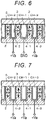
- FIG. 6 is a diagram illustrating a state around a periphery of the target channel CH-1 in the draw period PA.
- the switch control circuit 13 controls the switch 14 so that a potential of the target electrode 4-1 is set to the ground potential and both potentials of the adjacent electrodes 4-2 and 4-3 are set to the voltage + Va.
- the voltage - Va is respectively applied between the target electrode 4-1 and the adjacent electrode 4-2 and between the target electrode 4-1 and the adjacent electrode 4-3.
- a portion of the first piezoelectric member 2 and the second piezoelectric member 3 sandwiched between the target electrode 4-1 and the adjacent electrode 4-2 is orthogonal to a polarization direction, and an electric field from the adjacent electrode 4-2 toward the target electrode 4-1 acts.
- the portion of the first piezoelectric member 2 and the second piezoelectric member 3 sandwiched between the target electrode 4-1 and the adjacent electrode 4-2 is deformed to a side of the adjacent channel CH-2.
- a portion of the first piezoelectric member 2 and the second piezoelectric member 3 sandwiched between the target electrode 4-1 and the adjacent electrode 4-3 is also similarly deformed to a side of the adjacent channel CH-3.
- a volume of the target channel CH-1 is enlarged, and ink is sucked into the target channel CH-1 from the common ink chamber 51. That is, the state of the target channel CH-1 in the draw period PA corresponds to a first state.
- FIG. 7 is a diagram illustrating the state around the periphery of the target channel CH-1 in the release period PB.
- the switch control circuit 13 controls the switch 14 so that all the potentials of the target electrode 4-1 and the adjacent electrodes 4-2 and 4-3 are set to the voltage + Va.
- a potential difference does not occur between the target electrode 4-1 and the adjacent electrode 4-2
- an electric filed does not act on the portion of the first piezoelectric member 2 and the second piezoelectric member 3 sandwiched between the target electrode 4-1 and the adjacent electrode 4-2. Therefore, deformation caused by the action of the electric field does not occur in the portion of the first piezoelectric member 2 and the second piezoelectric member 3 sandwiched between the target electrode 4-1 and the adjacent electrode 4-2.
- the deformation also does not occur in the portion of the first piezoelectric member 2 and the second piezoelectric member 3 sandwiched between the target electrode 4-1 and the adjacent electrode 4-3.
- the volume of the target channel CH-1 becomes a neutral state.
- ink is not newly sucked into the target channel CH-1, and ink is not discharged from the target channel CH-1 via the target nozzle 61-1. That is, the state of the target channel CH-1 in the release period PB corresponds to a third state.
- FIG. 8 is a diagram illustrating the state around the periphery of the target channel CH-1 in the push period PC.
- the switch control circuit 13 controls the switch 14 so that the potential of the target electrode 4-1 is set to voltage + Va and both potentials of the adjacent electrodes 4-2 and 4-3 are set to the ground potentials. Accordingly, the voltage + Va is respectively applied between the target electrode 4-1 and the adjacent electrode 4-2 and between the target electrode 4-1 and the adjacent electrode 4-3.
- the portion of the first piezoelectric member 2 and the second piezoelectric member 3 sandwiched between the target electrode 4-1 and the adjacent electrode 4-2 is orthogonal to the polarization direction, and an electric field from the target electrode 4-1 toward the adjacent electrode 4-2 acts.
- the portion of the first piezoelectric member 2 and the second piezoelectric member 3 sandwiched between the target electrode 4-1 and the adjacent electrode 4-2 is deformed to a side of the target channel CH-1.
- the portion of the first piezoelectric member 2 and the second piezoelectric member 3 sandwiched between the target electrode 4-1 and the adjacent electrode 4-3 is also deformed to a side of the target channel CH-1.
- the volume of the target channel CH-1 is reduced, and ink is discharged from the target channel CH-1 via the target nozzle 61-1.
- a length of the push period PC is set to a short time of about 0.90 ⁇ sec.
- a small amount of ink for example, about 12 pL, is discharged from the target nozzle 61-1 in a state of the ink droplet. That is, the state of the target channel CH-1 in the push period PC corresponds to a second state.
- a first drop is discharged according to state transition in the order of draw, release, and push.
- the switch control circuit 13 controls the switch 14 so that all the potentials of the target electrode 4-1 and the adjacent electrodes 4-2 and 4-3 are set to the voltage + Va. That is, the switch control circuit 13 is in the same state as that of the release period PB.
- ink is not newly sucked into the target channel CH-1, and ink is not discharged from the target channel CH-1 via the target nozzle 61-1. That is, the state of the target channel CH-1 in the rest period PD corresponds to the third state.
- the pressure applied to the ink in the target channel CH-1 in the push period PC is reduced, and a meniscus of the ink in the target nozzle 61-1 changes to a concave shape on the side of the target channel CH-1.
- FIG. 9 is a diagram illustrating a state of a concave meniscus ME.
- a reference sign IN represents the ink in the target channel CH-1.
- An end part of the meniscus ME of the ink IN is located at a constricted part of the target nozzle 61-1, and a liquid surface is recessed.
- the waveform generation circuit 12 causes the nozzle to discharge a second drop by the state transition in the order of draw, release, and push in the same manner as that of the first drop.
- the waveform generation circuit 12 also causes the nozzle to discharge a third drop by the state transition in the order of draw, release, and push in the same manner as that of the first drop, and also provides the rest period PD between the second drop and the third drop.
- the waveform generation circuit 12, the switch control circuit 13, and the switch 14 drive the actuator including the first piezoelectric member 2 and the second piezoelectric member 3 so that the ink droplet as a droplet is repeatedly discharged from the nozzle 61 a plurality of times by sequentially forming the first state in the draw period PA, the third state in the release period PB, and the second state in the push period PC in a state of providing the third state in the rest period between the respective drops of the ink droplet. Therefore, a function as the drive unit is achieved by cooperation of the waveform generation circuit 12, the switch control circuit 13, and the switch 14.
- the rest period PD is provided between the respective drops of the ink droplet, and the meniscus ME is formed to be the concave shape prior to the state transition for performing the next drop, thereby making it possible to prevent the discharge speed after the second drop from decreasing.
- FIGS. 10 and 11 are diagrams illustrating a relationship between a length of the rest period PD and a discharge speed.
- FIG. 10 shows a result of respectively measuring the discharge speed for each of the first drop, the second drop, and the third drop by driving as described above by defining the length of the rest period PD as 0, UL/4, UL/2, 2UL/3, and UL.
- FIG. 11 is a table showing a result of determining the discharge speed, the flight state, and the voltage of the drive waveform with respect to the third drop in comparison with a case where the rest period PD is not provided.
- the discharge speed and the flight state of FIG. 11 are results of determination by rule of thumb visually by an observer from an image obtained by photographing the ink droplet discharged from the inkjet head 110.
- the lengths of the draw period PA, the release period PB, and the push period PC are respectively set to UL, 2UL, and 0.90 ⁇ sec.
- UL is time obtained by performing appropriate fraction processing when half the time of a natural vibration period of the channel CH is defined as pressure propagation time (AL: acoustic length).
- a type of specific processing to be applied as the fraction processing may be freely determined by a designer of the inkjet head 110.
- the discharge speed increases as the rest period PD generally becomes longer.
- the rest period PD exceeds UL and becomes longer, the discharge speed at the third drop decreases, and dot separation also occurs.
- the length of the rest period PD is set in a range of UL/2 or more and UL or less.
- the discharge speeds of the first drop, the second drop, and the third drop are almost the same as each other. Therefore, it is most desirable to set the rest period PD to UL.
- the rest period PD is provided after the push period PC of the preceding drop and before the draw period PA of the subsequent drop, such that it is possible to prevent a decrease in the discharge speed of the subsequent drop, and to reduce a variation in the discharge speed of each drop.
- accuracy of pixel formation can be improved and quality of a printed image can be improved.
- the inkjet head 110 can further reduce the variation in the discharge speed of each drop by setting the length of the rest period PD in the range of UL/2 or more and UL or less.
- the inkjet head 110 can minimize the variation in the discharge speed of each drop by setting the length of the rest period PD to UL.
- the waveform generation circuit 12 may be provided in the printer 100 outside the inkjet head 110.
- the embodiment can also be realized as a printer for other uses such as a printer for document printing, a printer for barcode printing, and a printer for printing a certificate such as a receipt or the like.
- the embodiment can also be realized as a printer for other uses other than image printing such as a printer for forming a three-dimensional object or the like. Therefore, the liquid to be discharged is not limited to ink, and may be a material for forming an object or the like.
- the three-division drive system is only an example, and a four-division drive system, a five-division drive system, or the like may be adopted.
Landscapes
- Particle Formation And Scattering Control In Inkjet Printers (AREA)
Abstract
According to one embodiment, a droplet discharge head includes a head body and a drive unit. The head body discharges a liquid sucked into a pressure chamber from a nozzle provided in communication with the pressure chamber by changing a volume of the pressure chamber by an actuator. The drive unit drives the actuator to selectively form a first state in which the liquid is sucked into the pressure chamber, a second state in which the liquid is pushed out from the pressure chamber into the nozzle, and a third state in which the liquid is not sucked and the liquid is not pushed out, and drives the actuator so that a droplet is repeatedly discharged from the nozzle a plurality of times by sequentially forming the first state, the third state, and the second state in a state of providing the third state between the respective drops of the droplet, when one pixel is formed.
Description
- Embodiments described herein relate generally to a droplet discharge head and a droplet discharge apparatus.
- A droplet discharge head is known as, for example, an inkjet head or the like. An end shooter type is known as one type of the inkjet head. The inkjet head of the end shooter type discharges ink, which is sucked from an end part of a pressure chamber into the pressure chamber, from a nozzle provided at an end part opposite to a side of the end part of the pressure chamber.
- When the above-described inkjet head continuously discharges ink a plurality of times with respect to one pixel by using a multi-drop method, a discharge speed after a second drop tends to be lower than a discharge speed of a first drop, which may affect accuracy of pixel formation.
- Considering such circumstances, it is desired to be able to reduce a variation in a discharge speed when continuous discharge is performed for one pixel a plurality of times.
-
-
FIG. 1 is a block diagram illustrating a configuration example of a printer according to an embodiment; -
FIG. 2 is a perspective view illustrating a part of an inkjet head illustrated inFIG. 1 in an exploded manner; -
FIG. 3 is a cross-sectional view of the inkjet head illustrated inFIG. 1 and a block diagram illustrating a main circuit configuration of a drive IC; -
FIG. 4 is a vertical cross-sectional view of the inkjet head illustrated inFIG. 1 ; -
FIG. 5 is a diagram illustrating an example of a drive waveform for discharging ink from one of a plurality of nozzles; -
FIG. 6 is a diagram illustrating a state around a periphery of a target channel during a draw period; -
FIG. 7 is a diagram illustrating the state around the periphery of the target channel during a release period; -
FIG. 8 is a diagram illustrating the state around the periphery of the target channel during a push period; -
FIG. 9 is a diagram illustrating a state of a concave meniscus; -
FIG. 10 is a diagram illustrating a relationship between a length of a rest period and a discharge speed; and -
FIG. 11 is a diagram illustrating the relationship between the length of the rest period and the discharge speed. - Embodiments described herein provide a droplet discharge head and a droplet discharge apparatus capable of reducing a variation in a discharge speed when continuous discharge is performed for one pixel a plurality of times.
- In general, according to one embodiment, a droplet discharge head includes a head body and a drive unit. The head body discharges a liquid sucked into a pressure chamber from a nozzle provided in communication with the pressure chamber by changing a volume of the pressure chamber by an actuator. The drive unit drives the actuator to selectively form a first state in which the liquid is sucked into the pressure chamber, a second state in which the liquid is pushed out from the pressure chamber into the nozzle, and a third state in which the liquid is not sucked and the liquid is not pushed out. In forming one pixel, the drive unit drives the actuator so that a droplet is repeatedly discharged from the nozzle a plurality of times by sequentially forming the first state, the third state, and the second state, with the third state further provided between the respective drops of the droplet.
- Preferably, given that pressure propagation time in the pressure chamber is UL, the drive unit sets 1/2 UL to UL as a period of forming the third state between the second state and formation of the first state for discharging the next droplet.
- Preferably, given that pressure propagation time in the pressure chamber is UL, the drive unit sets UL as a period of forming the third state between the second state and formation of the first state for discharging the next droplet.
- Preferably, the drive unit sets a period of forming the first state for discharging the droplet one time to UL, sets a period of forming the third state to 2UL, and sets a period of forming the second state to 0.9 µsec.
- There is also provided a droplet discharge apparatus, comprising the droplet discharge head as described above, wherein the drive unit is comprised in the droplet discharge apparatus outside the droplet discharge head.
- Hereinafter, a droplet discharge apparatus as an example of the embodiment will be described with reference to the drawings. In the following, an example of achieving the droplet discharge apparatus as a printer adapted for the use of printing an image by spraying an ink droplet on paper (a recording medium) will be described.
-
FIG. 1 is a block diagram illustrating a configuration example of aprinter 100 according to the embodiment. - As illustrated in
FIG. 1 , theprinter 100 includes aprocessor 101, amain memory 102, anauxiliary storage unit 103, anoperation panel 104, acommunication interface 105, aconveyance unit 106, aconveyance control unit 107, apump 108, apump drive unit 109, aninkjet head 110, and atransmission path 111. - The
processor 101, themain memory 102, and theauxiliary storage unit 103 are connected to each other with thetransmission path 111, thereby forming a computer that performs information processing for controlling theprinter 100. - The
processor 101 corresponds to a central portion of the computer. Theprocessor 101 executes the above-described information processing according to an information processing program such as an operating system, middleware, or an application program. - The
main memory 102 corresponds to a main memory portion of the computer. Themain memory 102 includes a non-volatile memory area and a volatile memory area. Themain memory 102 stores the information processing program in the non-volatile memory area. Themain memory 102 may store data necessary for theprocessor 101 to execute processing for controlling each unit in the non-volatile memory area or the volatile memory area. Themain memory 102 uses the volatile memory area as a work area where data can be appropriately rewritten by theprocessor 101. - The
auxiliary storage unit 103 corresponds to an auxiliary storage portion of the computer. As theauxiliary storage unit 103, well-known storage devices such as an electric erasable programmable read-only memory (EEPROM), a hard disk drive (HDD), a solid state drive (SSD), or the like can be used independently or in combination of a plurality thereof. Theauxiliary storage unit 103 stores data used by theprocessor 101 for performing various processing and data generated by the processing of theprocessor 101. Theauxiliary storage unit 103 stores the information processing program. - The
operation panel 104 includes an input device and a display device. Theoperation panel 104 inputs an instruction from an operator by the input device. Theoperation panel 104 displays various information to be notified to the operator by the display device. As theoperation panel 104, for example, a touch panel can be used. However, as the input device and the display device, various other devices can be appropriately used. - The
communication interface 105 transmits and receives data to and from an external device via a communication network such as a local area network (LAN) or the like. The external device is, for example, an information processing apparatus that requests printing with respect to theprinter 100. As thecommunication interface 105, a well-known device such as a communication device for LAN or the like can be used. - The
conveyance unit 106 includes a motor, a gear, a roller, or the like, and conveys paper in a state of crossing a flight path of an ink droplet discharged from theinkjet head 110. - The
conveyance control unit 107 controls theconveyance unit 106 so that the paper is conveyed at a predetermined timing synchronized with a discharge operation of the ink droplet by theinkjet head 110 under the control of theprocessor 101. - The
pump 108 supplies liquid ink from an ink tank which is not illustrated to theinkjet head 110. That is, ink is an example of a liquid. - The
pump drive unit 109 drives thepump 108 under the control of theprocessor 101. - The
inkjet head 110 discharges the ink supplied by thepump 108 as the ink droplet based upon print data. The ink droplet is an example of a droplet, and theinkjet head 110 is an example of a droplet discharge head. - The
transmission path 111 includes an address bus, a data bus, a control signal line, or the like, and transmits data and a control signal transmitted and received between respective connected units. -
FIG. 2 is a perspective view illustrating a part of theinkjet head 110 in an exploded manner.FIG. 3 is a cross-sectional view of theinkjet head 110 and a block diagram illustrating a main circuit configuration of a drive integrated circuit (IC) 10 illustrated inFIG. 2 .FIG. 4 is a vertical cross-sectional view of theinkjet head 110. In the following description of each of the drawings ofFIGS. 2 to 4 , a vertical direction in the drawing is defined as a vertical direction of theinkjet head 110. A right side inFIGS. 2 and4 and a back side inFIG. 3 are defined as a tip side. A left side inFIGS. 2 and4 and a front side inFIG. 3 are defined as a rear end side. - The
inkjet head 110 includes asubstrate 1, a firstpiezoelectric member 2, a secondpiezoelectric member 3, anelectrode 4, atop plate 5, anozzle plate 6, aconductive path 7, acircuit board 8, awire 9, and thedrive IC 10. - The
substrate 1 is an elongated plate-shaped member. It is desirable that thesubstrate 1 has a small dielectric constant. It is desirable that thesubstrate 1 has a small difference in a coefficient of thermal expansion between the firstpiezoelectric member 2 and the secondpiezoelectric member 3. Materials suitable for thesubstrate 1 are, for example, alumina (Al2O3), silicon nitride (Si3N4), silicon carbide (SiC), aluminum nitride (AlN), lead zirconate titanate (PZT), or the like. Materials of the firstpiezoelectric member 2 and the secondpiezoelectric member 3 are, for example, lead zirconate titanate (PZT), lithium niobate (LiNbO3), lithium tantalate (LiTaO3), or the like. - The first
piezoelectric member 2 is joined to an upper surface of thesubstrate 1. The secondpiezoelectric member 3 is joined onto the firstpiezoelectric member 2. As illustrated by an arrow inFIG. 3 , the firstpiezoelectric member 2 and the secondpiezoelectric member 3 are polarized in mutually opposite directions in a state of having a joint surface therebetween as a boundary. - A part of an upper side of a structure formed by stacking the first
piezoelectric member 2 and the secondpiezoelectric member 3 is cut out at a plurality of places from the tip side to the rear end side, and a plurality of long channels CH are formed thereat. A distance between adjacent channels CH is almost constant. For example, the plurality of channels CH are almost parallel to each other. The channel CH is opened on the tip side and a depth of the channel CH gradually decreases on the rear end side. A maximum depth, width and pitch of the channel CH are, for example, 300 µm, 80 µm and 169 µm. The number of channels CH is, for example, 318. - The
electrode 4 is a conductive film in a state of covering a side wall and a bottom surface of the channel CH. Theelectrode 4 has, for example, a two-layer structure of nickel (Ni) and gold (Au). Theelectrode 4 is uniformly formed in the channel CH by, for example, a plating method. A method for forming theelectrode 4 therein is not limited to the plating method, and may include a sputtering method, a vapor deposition method, or the like. - The
top plate 5 is joined to an upper surface of the secondpiezoelectric member 3 and closes an upper part of each of the plurality of channels CH. Acommon ink chamber 51 is formed in thetop plate 5. Thecommon ink chamber 51 is formed by providing a recessed part in the vicinity of an end part of a rear end side of a lower surface of thetop plate 5. Thecommon ink chamber 51 is located above all channels CH. The ink supplied from the ink tank to theinkjet head 110 by thepump 108 flows into thecommon ink chamber 51. - The
nozzle plate 6 is joined to an end surface of the tip side of the firstpiezoelectric member 2 and the secondpiezoelectric member 3, and closes the tip side of each of the plurality of channels CH. A plurality ofnozzles 61 are formed in thenozzle plate 6 in association with each of the plurality of channels CH. Thenozzle 61 connects one of the plurality of channels CH, which corresponds thereto, to the outside of theinkjet head 110. As illustrated inFIG. 4 , thenozzle 61 has a constricted part at a location slightly on the tip side from a center of thenozzle 61, and is gradually widened from the constricted part toward both the tip side and the rear end side. Thenozzle 61 is not limited to such shape. For example, thenozzle 61 may have a tapered truncated cone shape in which a nozzle diameter on a discharge surface side becomes smaller. Thenozzle 61 is formed as a set of three nozzles corresponding to three adjacent channels CH. The threenozzles 61 of the same set are shifted in the vertical direction at a regular distance as illustrated inFIGS. 2 and3 . - Accordingly, the channel CH is a closed space except a portion in contact with the
common ink chamber 51 and a portion in contact with thenozzle 61. The channel CH communicates with thecommon ink chamber 51 and thenozzle 61. The channel CH is also referred to as a pressure chamber or an ink chamber. - A plurality of
conductive paths 7 are provided in parallel from the tip side to the rear end side in a state of extending from the channel CH. The plurality ofconductive paths 7 are electrically connected to one correspondingelectrode 4 of a plurality ofelectrodes 4. - The
circuit board 8 is juxtaposed with the firstpiezoelectric member 2 and the secondpiezoelectric member 3, and is joined to an upper surface on the rear end side of thesubstrate 1. As thecircuit board 8, for example, a printed circuit board is used. A plurality ofconductive paths 81 and a plurality ofconductive paths 82 are formed on an upper surface of thecircuit board 8, for example, as printed wiring. The plurality ofconductive paths 81 respectively correspond to the plurality ofelectrodes 4. Theconductive path 82 is connected to an interface circuit (not illustrated) for being connected to thetransmission path 111. - The
wire 9 is a wire formed of a conductive material. A plurality ofwires 9 are provided in parallel. The plurality ofwires 9 respectively correspond to the plurality ofelectrodes 4 and the plurality ofconductive paths 81. One end of thewire 9 is connected to one correspondingelectrode 4 of the plurality ofelectrodes 4. The other end of thewire 9 is connected to one correspondingconductive path 81 of the plurality ofconductive paths 81. Accordingly, thewire 9 electrically connects thecorresponding electrode 4 and the correspondingconductive path 81. - The
drive IC 10 is mounted on thecircuit board 8 in a state of being electrically connected to theconductive paths drive IC 10 drives a head body to allow thenozzle 61 to discharge ink. - As illustrated in
FIG. 3 , thedrive IC 10 includes apixel separation circuit 11, awaveform generation circuit 12, aswitch control circuit 13, and a plurality ofswitches 14. - Print data is inputted to the
pixel separation circuit 11 via theconductive path 82. The print data is a set of pixel data representing a gradation value for each pixel. Thepixel separation circuit 11 separates the pixel data in the print data into three groups for eachcorresponding nozzle 61 of which vertical position is the same as illustratedFIG. 3 . That is, thepixel separation circuit 11 separates the pixel data so that the pixel data corresponding to each of the threenozzles 61 belonging to the same set belongs to different groups, respectively. Next, thepixel separation circuit 11 provides the pixel data belonging to each group to thewaveform generation circuit 12 in parallel at respectively different timings. As a result, theinkjet head 110 is a so-called three-division drive system in which pixel formation for one line is performed three times. Control for correctly printing an image by the three-division drive may be the same as that of another existing inkjet head of the three-division drive system. - The
waveform generation circuit 12 determines the number of drops for forming one pixel based upon each gradation value of the pixel data. Next, thewaveform generation circuit 12 generates a drive waveform, which will be described later, for continuously discharging the ink droplets of the determined number of drops. Next, thewaveform generation circuit 12 provides the drive waveform related to each of the pixel data belonging to one group to theswitch control circuit 13 in parallel. - The
switch control circuit 13 controls a plurality ofswitches 14 according to the drive waveform as described later. - The plurality of
switches 14 are electrically connected to one correspondingelectrode 4 of the plurality ofelectrodes 4 via theconductive path 81, thewire 9, and theconductive path 7.FIG. 3 illustrates only threeswitches 14 respectively corresponding to threeelectrodes 4 located at the center of the cross-sectional view. Theswitch 14 selectively forms two states in which a potential of thecorresponding electrode 4 is set to a voltage + Va or a ground potential under the control of theswitch control circuit 13. - The
inkjet head 110 having the above-described configuration is formed in such a manner that the head body including the firstpiezoelectric member 2, the secondpiezoelectric member 3, theelectrode 4, thetop plate 5, thenozzle plate 6, and theconductive path 7, and the drive unit including thecircuit board 8, thewire 9, and thedrive IC 10 are integrated to be connected to each other by thesubstrate 1. Theinkjet head 110 is an end shooter type that discharges ink sucked from the rear end side of the head body from the tip side. Theinkjet head 110 is a shared wall type in which the firstpiezoelectric member 2 and the secondpiezoelectric member 3 located between two channels CH are shared as an actuator for changing a volume of the two channels CH. - Next, an operation of the
printer 100 configured as described above will be described. A characteristic operation of theprinter 100 is that the head body is driven by thedrive IC 10 when image printing is performed by the multi-drop method, and other operations thereof may be the same as those of an existing printer of the same type. Therefore, hereinafter, the characteristic operation thereof will be mainly described. -
FIG. 5 is a diagram illustrating an example of the drive waveform for discharging ink from one of the plurality ofnozzles 61. - In the description of
FIG. 5 , onenozzle 61 in which ink is discharged by the driving of the drive waveform illustrated inFIG. 5 is referred to as a target nozzle 61-1. One channel CH connected to the target nozzle 61-1 is referred to as a target channel CH-1. Theelectrode 4 surrounding the target channel CH-1 is referred to as a target electrode 4-1. Two channels CH adjacent to the target channel CH-1 are respectively referred to as adjacent channels CH-2 and CH-3. Twoelectrodes 4 surrounding the adjacent channels CH-2 and CH-3 are respectively referred to as adjacent electrodes 4-2 and 4-3. - The drive waveform illustrated in
FIG. 5 is a drive waveform for generating continuous discharge of three drops for forming one pixel from the target nozzle 61-1. - When the ink droplets of three drops are continuously discharged, the
waveform generation circuit 12 provided in thedrive IC 10 drives theinkjet head 110 by the drive waveform illustrated inFIG. 5 . A period PA inFIG. 5 is a draw period. A period PB is a release period. A period PC is a push period. A period PD is a rest period. -
FIG. 6 is a diagram illustrating a state around a periphery of the target channel CH-1 in the draw period PA. - In the draw period PA, the
switch control circuit 13 controls theswitch 14 so that a potential of the target electrode 4-1 is set to the ground potential and both potentials of the adjacent electrodes 4-2 and 4-3 are set to the voltage + Va. As a result, the voltage - Va is respectively applied between the target electrode 4-1 and the adjacent electrode 4-2 and between the target electrode 4-1 and the adjacent electrode 4-3. Here, a portion of the firstpiezoelectric member 2 and the secondpiezoelectric member 3 sandwiched between the target electrode 4-1 and the adjacent electrode 4-2 is orthogonal to a polarization direction, and an electric field from the adjacent electrode 4-2 toward the target electrode 4-1 acts. By such action, the portion of the firstpiezoelectric member 2 and the secondpiezoelectric member 3 sandwiched between the target electrode 4-1 and the adjacent electrode 4-2 is deformed to a side of the adjacent channel CH-2. A portion of the firstpiezoelectric member 2 and the secondpiezoelectric member 3 sandwiched between the target electrode 4-1 and the adjacent electrode 4-3 is also similarly deformed to a side of the adjacent channel CH-3. As a result, a volume of the target channel CH-1 is enlarged, and ink is sucked into the target channel CH-1 from thecommon ink chamber 51. That is, the state of the target channel CH-1 in the draw period PA corresponds to a first state. -
FIG. 7 is a diagram illustrating the state around the periphery of the target channel CH-1 in the release period PB. - In the release period PB, the
switch control circuit 13 controls theswitch 14 so that all the potentials of the target electrode 4-1 and the adjacent electrodes 4-2 and 4-3 are set to the voltage + Va. Here, since a potential difference does not occur between the target electrode 4-1 and the adjacent electrode 4-2, an electric filed does not act on the portion of the firstpiezoelectric member 2 and the secondpiezoelectric member 3 sandwiched between the target electrode 4-1 and the adjacent electrode 4-2. Therefore, deformation caused by the action of the electric field does not occur in the portion of the firstpiezoelectric member 2 and the secondpiezoelectric member 3 sandwiched between the target electrode 4-1 and the adjacent electrode 4-2. In the same manner, the deformation also does not occur in the portion of the firstpiezoelectric member 2 and the secondpiezoelectric member 3 sandwiched between the target electrode 4-1 and the adjacent electrode 4-3. As a result, the volume of the target channel CH-1 becomes a neutral state. Here, ink is not newly sucked into the target channel CH-1, and ink is not discharged from the target channel CH-1 via the target nozzle 61-1. That is, the state of the target channel CH-1 in the release period PB corresponds to a third state. -
FIG. 8 is a diagram illustrating the state around the periphery of the target channel CH-1 in the push period PC. - In the push period PC, the
switch control circuit 13 controls theswitch 14 so that the potential of the target electrode 4-1 is set to voltage + Va and both potentials of the adjacent electrodes 4-2 and 4-3 are set to the ground potentials. Accordingly, the voltage + Va is respectively applied between the target electrode 4-1 and the adjacent electrode 4-2 and between the target electrode 4-1 and the adjacent electrode 4-3. Here, the portion of the firstpiezoelectric member 2 and the secondpiezoelectric member 3 sandwiched between the target electrode 4-1 and the adjacent electrode 4-2 is orthogonal to the polarization direction, and an electric field from the target electrode 4-1 toward the adjacent electrode 4-2 acts. By such action, the portion of the firstpiezoelectric member 2 and the secondpiezoelectric member 3 sandwiched between the target electrode 4-1 and the adjacent electrode 4-2 is deformed to a side of the target channel CH-1. In the same manner, the portion of the firstpiezoelectric member 2 and the secondpiezoelectric member 3 sandwiched between the target electrode 4-1 and the adjacent electrode 4-3 is also deformed to a side of the target channel CH-1. As a result, the volume of the target channel CH-1 is reduced, and ink is discharged from the target channel CH-1 via the target nozzle 61-1. For example, a length of the push period PC is set to a short time of about 0.90 µsec. As a result, a small amount of ink, for example, about 12 pL, is discharged from the target nozzle 61-1 in a state of the ink droplet. That is, the state of the target channel CH-1 in the push period PC corresponds to a second state. - As described above, a first drop is discharged according to state transition in the order of draw, release, and push.
- In the rest period PD, the
switch control circuit 13 controls theswitch 14 so that all the potentials of the target electrode 4-1 and the adjacent electrodes 4-2 and 4-3 are set to the voltage + Va. That is, theswitch control circuit 13 is in the same state as that of the release period PB. Here, ink is not newly sucked into the target channel CH-1, and ink is not discharged from the target channel CH-1 via the target nozzle 61-1. That is, the state of the target channel CH-1 in the rest period PD corresponds to the third state. The pressure applied to the ink in the target channel CH-1 in the push period PC is reduced, and a meniscus of the ink in the target nozzle 61-1 changes to a concave shape on the side of the target channel CH-1. -
FIG. 9 is a diagram illustrating a state of a concave meniscus ME. - In
FIG. 9 , a reference sign IN represents the ink in the target channel CH-1. An end part of the meniscus ME of the ink IN is located at a constricted part of the target nozzle 61-1, and a liquid surface is recessed. - After the end of the rest period PD, the
waveform generation circuit 12 causes the nozzle to discharge a second drop by the state transition in the order of draw, release, and push in the same manner as that of the first drop. - The
waveform generation circuit 12 also causes the nozzle to discharge a third drop by the state transition in the order of draw, release, and push in the same manner as that of the first drop, and also provides the rest period PD between the second drop and the third drop. - As described above, the
waveform generation circuit 12, theswitch control circuit 13, and theswitch 14 drive the actuator including the firstpiezoelectric member 2 and the secondpiezoelectric member 3 so that the ink droplet as a droplet is repeatedly discharged from the nozzle 61 a plurality of times by sequentially forming the first state in the draw period PA, the third state in the release period PB, and the second state in the push period PC in a state of providing the third state in the rest period between the respective drops of the ink droplet. Therefore, a function as the drive unit is achieved by cooperation of thewaveform generation circuit 12, theswitch control circuit 13, and theswitch 14. - As such, even while the ink droplet is continuously discharged by multi-drop, the rest period PD is provided between the respective drops of the ink droplet, and the meniscus ME is formed to be the concave shape prior to the state transition for performing the next drop, thereby making it possible to prevent the discharge speed after the second drop from decreasing.
-
FIGS. 10 and 11 are diagrams illustrating a relationship between a length of the rest period PD and a discharge speed. -
FIG. 10 shows a result of respectively measuring the discharge speed for each of the first drop, the second drop, and the third drop by driving as described above by defining the length of the rest period PD as 0, UL/4, UL/2, 2UL/3, and UL.FIG. 11 is a table showing a result of determining the discharge speed, the flight state, and the voltage of the drive waveform with respect to the third drop in comparison with a case where the rest period PD is not provided. The discharge speed and the flight state ofFIG. 11 are results of determination by rule of thumb visually by an observer from an image obtained by photographing the ink droplet discharged from theinkjet head 110. - The lengths of the draw period PA, the release period PB, and the push period PC are respectively set to UL, 2UL, and 0.90 µsec.
- Here, UL is time obtained by performing appropriate fraction processing when half the time of a natural vibration period of the channel CH is defined as pressure propagation time (AL: acoustic length). As an example, UL is 2 µsec or less. A type of specific processing to be applied as the fraction processing may be freely determined by a designer of the
inkjet head 110. - As can be seen from
FIG. 10 , between 0 and UL, the discharge speed increases as the rest period PD generally becomes longer. As can be seen fromFIG. 11 , when the rest period PD exceeds UL and becomes longer, the discharge speed at the third drop decreases, and dot separation also occurs. - As described above, it is desirable that the length of the rest period PD is set in a range of UL/2 or more and UL or less. As can be seen from
FIG. 10 , when the length of the rest period PD is UL, the discharge speeds of the first drop, the second drop, and the third drop are almost the same as each other. Therefore, it is most desirable to set the rest period PD to UL. - As described above, in the
inkjet head 110, when the continuous discharge is performed for one pixel a plurality of times, the rest period PD is provided after the push period PC of the preceding drop and before the draw period PA of the subsequent drop, such that it is possible to prevent a decrease in the discharge speed of the subsequent drop, and to reduce a variation in the discharge speed of each drop. As a result, accuracy of pixel formation can be improved and quality of a printed image can be improved. - The
inkjet head 110 can further reduce the variation in the discharge speed of each drop by setting the length of the rest period PD in the range of UL/2 or more and UL or less. - The
inkjet head 110 can minimize the variation in the discharge speed of each drop by setting the length of the rest period PD to UL. - Various modifications of the embodiment can be made as follows.
- The
waveform generation circuit 12 may be provided in theprinter 100 outside theinkjet head 110. - The embodiment can also be realized as a printer for other uses such as a printer for document printing, a printer for barcode printing, and a printer for printing a certificate such as a receipt or the like. Alternatively, the embodiment can also be realized as a printer for other uses other than image printing such as a printer for forming a three-dimensional object or the like. Therefore, the liquid to be discharged is not limited to ink, and may be a material for forming an object or the like.
- The three-division drive system is only an example, and a four-division drive system, a five-division drive system, or the like may be adopted.
- While certain embodiments have been described, these embodiments have been presented by way of example only, and are not intended to limit the scope of the inventions. Indeed, the novel embodiments described herein may be embodied in a variety of other forms; furthermore, various omissions, substitutions and changes in the form of the embodiments described herein may be made without departing from the scope of the inventions. The accompanying claims and their equivalents are intended to cover such forms or modifications as would fall within the scope of the inventions.
Claims (5)
- A droplet discharge head, comprising:a head body configured to discharge a liquid sucked into a pressure chamber from a nozzle provided in communication with the pressure chamber by changing a volume of the pressure chamber by an actuator; anda drive unit configured to:drive the actuator to selectively form a first state in which the liquid is sucked into the pressure chamber, a second state in which the liquid is pushed out from the pressure chamber into the nozzle, and a third state in which the liquid is not sucked and the liquid is not pushed out; andin forming one pixel, drive the actuator so that a droplet is repeatedly discharged from the nozzle a plurality of times by sequentially forming the first state, the third state, and the second state, with the third state further provided between the respective drops of the droplet.
- The droplet discharge head according to claim 1, wherein
given that pressure propagation time in the pressure chamber is UL, the drive unit sets 1/2 UL to UL as a period of forming the third state between the second state and formation of the first state for discharging the next droplet. - The droplet discharge head according to claim 1, wherein
given that pressure propagation time in the pressure chamber is UL, the drive unit sets UL as a period of forming the third state between the second state and formation of the first state for discharging the next droplet. - The droplet discharge head according to claim 2 or 3, wherein
the drive unit sets a period of forming the first state for discharging the droplet one time to UL, sets a period of forming the third state to 2UL, and sets a period of forming the second state to 0.9 µsec. - A droplet discharge apparatus, comprising the droplet discharge head according to any one of claims 1 to 4, wherein the drive unit is comprised in the droplet discharge apparatus outside the droplet discharge head.
Applications Claiming Priority (1)
| Application Number | Priority Date | Filing Date | Title |
|---|---|---|---|
| JP2020204176A JP2022091369A (en) | 2020-12-09 | 2020-12-09 | Droplet ejection head and droplet ejection device |
Publications (1)
| Publication Number | Publication Date |
|---|---|
| EP4011626A1 true EP4011626A1 (en) | 2022-06-15 |
Family
ID=76034423
Family Applications (1)
| Application Number | Title | Priority Date | Filing Date |
|---|---|---|---|
| EP21173414.0A Withdrawn EP4011626A1 (en) | 2020-12-09 | 2021-05-11 | Droplet discharge head and droplet discharge apparatus |
Country Status (3)
| Country | Link |
|---|---|
| EP (1) | EP4011626A1 (en) |
| JP (1) | JP2022091369A (en) |
| CN (1) | CN114603995A (en) |
Citations (4)
| Publication number | Priority date | Publication date | Assignee | Title |
|---|---|---|---|---|
| US20080252672A1 (en) * | 2007-04-12 | 2008-10-16 | Toshiba Tec Kabushiki Kaisha | Inkjet head driving apparatus and driving method |
| US20130182024A1 (en) * | 2012-01-12 | 2013-07-18 | Toshiba Tec Kabushiki Kaisha | Inkjet head and an inkjet recording device |
| US20150298455A1 (en) * | 2014-04-16 | 2015-10-22 | Riso Kagaku Corporation | Inkjet printer |
| US20200101721A1 (en) * | 2018-10-02 | 2020-04-02 | Toshiba Tec Kabushiki Kaisha | Liquid discharge head and printer |
Family Cites Families (3)
| Publication number | Priority date | Publication date | Assignee | Title |
|---|---|---|---|---|
| JP6368691B2 (en) * | 2015-07-06 | 2018-08-01 | 株式会社東芝 | Inkjet head and inkjet printer |
| US11648771B2 (en) * | 2018-01-05 | 2023-05-16 | Konica Minolta, Inc. | Inkjet recording device and inkjet head drive method |
| JP7189050B2 (en) * | 2019-03-01 | 2022-12-13 | 東芝テック株式会社 | Liquid ejection head and printer |
-
2020
- 2020-12-09 JP JP2020204176A patent/JP2022091369A/en active Pending
-
2021
- 2021-05-11 EP EP21173414.0A patent/EP4011626A1/en not_active Withdrawn
- 2021-08-12 CN CN202110925482.1A patent/CN114603995A/en not_active Withdrawn
Patent Citations (4)
| Publication number | Priority date | Publication date | Assignee | Title |
|---|---|---|---|---|
| US20080252672A1 (en) * | 2007-04-12 | 2008-10-16 | Toshiba Tec Kabushiki Kaisha | Inkjet head driving apparatus and driving method |
| US20130182024A1 (en) * | 2012-01-12 | 2013-07-18 | Toshiba Tec Kabushiki Kaisha | Inkjet head and an inkjet recording device |
| US20150298455A1 (en) * | 2014-04-16 | 2015-10-22 | Riso Kagaku Corporation | Inkjet printer |
| US20200101721A1 (en) * | 2018-10-02 | 2020-04-02 | Toshiba Tec Kabushiki Kaisha | Liquid discharge head and printer |
Also Published As
| Publication number | Publication date |
|---|---|
| CN114603995A (en) | 2022-06-10 |
| JP2022091369A (en) | 2022-06-21 |
Similar Documents
| Publication | Publication Date | Title |
|---|---|---|
| JPH05301342A (en) | Ink jet printing head | |
| US20180264810A1 (en) | Ink jet head and ink jet recording apparatus | |
| CN111634121B (en) | Liquid jets and printers | |
| JP6450533B2 (en) | Inkjet head and inkjet printer | |
| US10710364B2 (en) | Liquid discharge head and printer | |
| US20180272698A1 (en) | Inkjet head, inkjet recording apparatus, and discharging method | |
| US11059285B2 (en) | Liquid discharge head and printer | |
| CN110978794B (en) | Liquid ejecting head and printer | |
| EP3928989B1 (en) | Liquid ejection head and printer | |
| JP2022091369A (en) | Droplet ejection head and droplet ejection device | |
| US12528289B2 (en) | Liquid droplet discharging apparatus | |
| EP4052908A1 (en) | Droplet discharge head, drive circuit thereof, and printer | |
| JP7242940B2 (en) | Liquid ejection head and printer | |
| US11718090B2 (en) | Liquid discharge head, liquid discharge device, and liquid discharge method | |
| US20240217232A1 (en) | Liquid droplet discharging apparatus | |
| JP2020152070A (en) | Liquid discharge head and liquid discharge device | |
| EP3974187A1 (en) | Liquid droplet discharge head and printer | |
| JP2020192690A (en) | Liquid discharge head and printer | |
| JPH10128970A (en) | Ink jet recording head and driving method |
Legal Events
| Date | Code | Title | Description |
|---|---|---|---|
| PUAI | Public reference made under article 153(3) epc to a published international application that has entered the european phase |
Free format text: ORIGINAL CODE: 0009012 |
|
| STAA | Information on the status of an ep patent application or granted ep patent |
Free format text: STATUS: THE APPLICATION HAS BEEN PUBLISHED |
|
| AK | Designated contracting states |
Kind code of ref document: A1 Designated state(s): AL AT BE BG CH CY CZ DE DK EE ES FI FR GB GR HR HU IE IS IT LI LT LU LV MC MK MT NL NO PL PT RO RS SE SI SK SM TR |
|
| STAA | Information on the status of an ep patent application or granted ep patent |
Free format text: STATUS: THE APPLICATION IS DEEMED TO BE WITHDRAWN |
|
| 18D | Application deemed to be withdrawn |
Effective date: 20221216 |