EP4011576A1 - Superabsorbent polymer hydrogel chopper - Google Patents
Superabsorbent polymer hydrogel chopper Download PDFInfo
- Publication number
- EP4011576A1 EP4011576A1 EP21759834.1A EP21759834A EP4011576A1 EP 4011576 A1 EP4011576 A1 EP 4011576A1 EP 21759834 A EP21759834 A EP 21759834A EP 4011576 A1 EP4011576 A1 EP 4011576A1
- Authority
- EP
- European Patent Office
- Prior art keywords
- hydrogel
- support
- barrel body
- superabsorbent polymer
- chopping device
- Prior art date
- Legal status (The legal status is an assumption and is not a legal conclusion. Google has not performed a legal analysis and makes no representation as to the accuracy of the status listed.)
- Granted
Links
Images




Classifications
-
- B—PERFORMING OPERATIONS; TRANSPORTING
- B29—WORKING OF PLASTICS; WORKING OF SUBSTANCES IN A PLASTIC STATE IN GENERAL
- B29B—PREPARATION OR PRETREATMENT OF THE MATERIAL TO BE SHAPED; MAKING GRANULES OR PREFORMS; RECOVERY OF PLASTICS OR OTHER CONSTITUENTS OF WASTE MATERIAL CONTAINING PLASTICS
- B29B9/00—Making granules
- B29B9/02—Making granules by dividing preformed material
- B29B9/06—Making granules by dividing preformed material in the form of filamentary material, e.g. combined with extrusion
-
- B—PERFORMING OPERATIONS; TRANSPORTING
- B26—HAND CUTTING TOOLS; CUTTING; SEVERING
- B26D—CUTTING; DETAILS COMMON TO MACHINES FOR PERFORATING, PUNCHING, CUTTING-OUT, STAMPING-OUT OR SEVERING
- B26D3/00—Cutting work characterised by the nature of the cut made; Apparatus therefor
- B26D3/24—Cutting work characterised by the nature of the cut made; Apparatus therefor to obtain segments other than slices, e.g. cutting pies
-
- B—PERFORMING OPERATIONS; TRANSPORTING
- B02—CRUSHING, PULVERISING, OR DISINTEGRATING; PREPARATORY TREATMENT OF GRAIN FOR MILLING
- B02C—CRUSHING, PULVERISING, OR DISINTEGRATING IN GENERAL; MILLING GRAIN
- B02C18/00—Disintegrating by knives or other cutting or tearing members which chop material into fragments
- B02C18/30—Mincing machines with perforated discs and feeding worms
-
- B—PERFORMING OPERATIONS; TRANSPORTING
- B26—HAND CUTTING TOOLS; CUTTING; SEVERING
- B26D—CUTTING; DETAILS COMMON TO MACHINES FOR PERFORATING, PUNCHING, CUTTING-OUT, STAMPING-OUT OR SEVERING
- B26D5/00—Arrangements for operating and controlling machines or devices for cutting, cutting-out, stamping-out, punching, perforating, or severing by means other than cutting
- B26D5/20—Arrangements for operating and controlling machines or devices for cutting, cutting-out, stamping-out, punching, perforating, or severing by means other than cutting with interrelated action between the cutting member and work feed
- B26D5/22—Arrangements for operating and controlling machines or devices for cutting, cutting-out, stamping-out, punching, perforating, or severing by means other than cutting with interrelated action between the cutting member and work feed having the cutting member and work feed mechanically connected
-
- B—PERFORMING OPERATIONS; TRANSPORTING
- B26—HAND CUTTING TOOLS; CUTTING; SEVERING
- B26D—CUTTING; DETAILS COMMON TO MACHINES FOR PERFORATING, PUNCHING, CUTTING-OUT, STAMPING-OUT OR SEVERING
- B26D7/00—Details of apparatus for cutting, cutting-out, stamping-out, punching, perforating, or severing by means other than cutting
- B26D7/06—Arrangements for feeding or delivering work of other than sheet, web, or filamentary form
- B26D7/0641—Arrangements for feeding or delivering work of other than sheet, web, or filamentary form using chutes, hoppers, magazines
-
- B—PERFORMING OPERATIONS; TRANSPORTING
- B26—HAND CUTTING TOOLS; CUTTING; SEVERING
- B26D—CUTTING; DETAILS COMMON TO MACHINES FOR PERFORATING, PUNCHING, CUTTING-OUT, STAMPING-OUT OR SEVERING
- B26D7/00—Details of apparatus for cutting, cutting-out, stamping-out, punching, perforating, or severing by means other than cutting
- B26D7/06—Arrangements for feeding or delivering work of other than sheet, web, or filamentary form
- B26D7/0666—Arrangements for feeding or delivering work of other than sheet, web, or filamentary form by screw or rotary spiral conveyors
-
- B—PERFORMING OPERATIONS; TRANSPORTING
- B29—WORKING OF PLASTICS; WORKING OF SUBSTANCES IN A PLASTIC STATE IN GENERAL
- B29B—PREPARATION OR PRETREATMENT OF THE MATERIAL TO BE SHAPED; MAKING GRANULES OR PREFORMS; RECOVERY OF PLASTICS OR OTHER CONSTITUENTS OF WASTE MATERIAL CONTAINING PLASTICS
- B29B7/00—Mixing; Kneading
- B29B7/30—Mixing; Kneading continuous, with mechanical mixing or kneading devices
- B29B7/34—Mixing; Kneading continuous, with mechanical mixing or kneading devices with movable mixing or kneading devices
- B29B7/38—Mixing; Kneading continuous, with mechanical mixing or kneading devices with movable mixing or kneading devices rotary
- B29B7/40—Mixing; Kneading continuous, with mechanical mixing or kneading devices with movable mixing or kneading devices rotary with single shaft
- B29B7/42—Mixing; Kneading continuous, with mechanical mixing or kneading devices with movable mixing or kneading devices rotary with single shaft with screw or helix
- B29B7/422—Mixing; Kneading continuous, with mechanical mixing or kneading devices with movable mixing or kneading devices rotary with single shaft with screw or helix with screw sections co-operating, e.g. intermeshing, with elements on the wall of the surrounding casing
-
- B—PERFORMING OPERATIONS; TRANSPORTING
- B29—WORKING OF PLASTICS; WORKING OF SUBSTANCES IN A PLASTIC STATE IN GENERAL
- B29B—PREPARATION OR PRETREATMENT OF THE MATERIAL TO BE SHAPED; MAKING GRANULES OR PREFORMS; RECOVERY OF PLASTICS OR OTHER CONSTITUENTS OF WASTE MATERIAL CONTAINING PLASTICS
- B29B7/00—Mixing; Kneading
- B29B7/30—Mixing; Kneading continuous, with mechanical mixing or kneading devices
- B29B7/58—Component parts, details or accessories; Auxiliary operations
- B29B7/60—Component parts, details or accessories; Auxiliary operations for feeding, e.g. end guides for the incoming material
-
- B—PERFORMING OPERATIONS; TRANSPORTING
- B29—WORKING OF PLASTICS; WORKING OF SUBSTANCES IN A PLASTIC STATE IN GENERAL
- B29B—PREPARATION OR PRETREATMENT OF THE MATERIAL TO BE SHAPED; MAKING GRANULES OR PREFORMS; RECOVERY OF PLASTICS OR OTHER CONSTITUENTS OF WASTE MATERIAL CONTAINING PLASTICS
- B29B9/00—Making granules
- B29B9/12—Making granules characterised by structure or composition
-
- B—PERFORMING OPERATIONS; TRANSPORTING
- B29—WORKING OF PLASTICS; WORKING OF SUBSTANCES IN A PLASTIC STATE IN GENERAL
- B29C—SHAPING OR JOINING OF PLASTICS; SHAPING OF MATERIAL IN A PLASTIC STATE, NOT OTHERWISE PROVIDED FOR; AFTER-TREATMENT OF THE SHAPED PRODUCTS, e.g. REPAIRING
- B29C48/00—Extrusion moulding, i.e. expressing the moulding material through a die or nozzle which imparts the desired form; Apparatus therefor
- B29C48/14—Extrusion moulding, i.e. expressing the moulding material through a die or nozzle which imparts the desired form; Apparatus therefor characterised by the particular extruding conditions, e.g. in a modified atmosphere or by using vibration
- B29C48/142—Extrusion moulding, i.e. expressing the moulding material through a die or nozzle which imparts the desired form; Apparatus therefor characterised by the particular extruding conditions, e.g. in a modified atmosphere or by using vibration using force fields, e.g. gravity or electrical fields
-
- C—CHEMISTRY; METALLURGY
- C08—ORGANIC MACROMOLECULAR COMPOUNDS; THEIR PREPARATION OR CHEMICAL WORKING-UP; COMPOSITIONS BASED THEREON
- C08J—WORKING-UP; GENERAL PROCESSES OF COMPOUNDING; AFTER-TREATMENT NOT COVERED BY SUBCLASSES C08B, C08C, C08F, C08G or C08H
- C08J3/00—Processes of treating or compounding macromolecular substances
- C08J3/02—Making solutions, dispersions, lattices or gels by other methods than by solution, emulsion or suspension polymerisation techniques
- C08J3/03—Making solutions, dispersions, lattices or gels by other methods than by solution, emulsion or suspension polymerisation techniques in aqueous media
- C08J3/075—Macromolecular gels
-
- C—CHEMISTRY; METALLURGY
- C08—ORGANIC MACROMOLECULAR COMPOUNDS; THEIR PREPARATION OR CHEMICAL WORKING-UP; COMPOSITIONS BASED THEREON
- C08J—WORKING-UP; GENERAL PROCESSES OF COMPOUNDING; AFTER-TREATMENT NOT COVERED BY SUBCLASSES C08B, C08C, C08F, C08G or C08H
- C08J3/00—Processes of treating or compounding macromolecular substances
- C08J3/12—Powdering or granulating
-
- B—PERFORMING OPERATIONS; TRANSPORTING
- B29—WORKING OF PLASTICS; WORKING OF SUBSTANCES IN A PLASTIC STATE IN GENERAL
- B29C—SHAPING OR JOINING OF PLASTICS; SHAPING OF MATERIAL IN A PLASTIC STATE, NOT OTHERWISE PROVIDED FOR; AFTER-TREATMENT OF THE SHAPED PRODUCTS, e.g. REPAIRING
- B29C48/00—Extrusion moulding, i.e. expressing the moulding material through a die or nozzle which imparts the desired form; Apparatus therefor
- B29C48/25—Component parts, details or accessories; Auxiliary operations
- B29C48/265—Support structures or bases for apparatus, e.g. frames
-
- Y—GENERAL TAGGING OF NEW TECHNOLOGICAL DEVELOPMENTS; GENERAL TAGGING OF CROSS-SECTIONAL TECHNOLOGIES SPANNING OVER SEVERAL SECTIONS OF THE IPC; TECHNICAL SUBJECTS COVERED BY FORMER USPC CROSS-REFERENCE ART COLLECTIONS [XRACs] AND DIGESTS
- Y02—TECHNOLOGIES OR APPLICATIONS FOR MITIGATION OR ADAPTATION AGAINST CLIMATE CHANGE
- Y02W—CLIMATE CHANGE MITIGATION TECHNOLOGIES RELATED TO WASTEWATER TREATMENT OR WASTE MANAGEMENT
- Y02W30/00—Technologies for solid waste management
- Y02W30/50—Reuse, recycling or recovery technologies
- Y02W30/62—Plastics recycling; Rubber recycling
Definitions
- the present invention relates to a superabsorbent polymer hydrogel chopping device capable of smoothly chopping a hydrogel.
- a super absorbent polymer is a synthetic polymer material that may absorb water 500 to 1,000 times its own weight, and each developer calls the SAP by other names such as super absorbency material (SAM) or absorbent gel material (AGM), etc.
- SAM super absorbency material
- AGM absorbent gel material
- the SAP as described above began to be put to practical use as a sanitary tool, and presently, is widely used as a soil repair agent for gardening, a water-stop material for civil engineering and construction, a sheet for seeding, a freshness maintenance agent in a food distribution field, a material for poultice, etc., as well as for hygiene products such as children's paper diapers.
- a thermal polymerization method in which a hydrogel polymer is broken, cooled, and polymerized in a kneader equipped with several shafts, and a photopolymerization method in which a high concentration aqueous solution is irradiated with ultraviolet rays or the like on a belt to perform polymerization and drying simultaneously, and the like are known.
- a hydrogel or hydrogel polymer obtained through the polymerization reaction as described above is generally pulverized through a drying process and then comes to the market as a powdery product.
- a process of primarily pulverizing the hydrogel polymer after polymerization is disclosed.
- a chopper is mainly used in a primary pulverizing process of the hydrogel.
- the chopper includes a screw for moving the hydrogel, a barrel including a spiral, a cutter blade for cutting the hydrogel, and a perforated plate through which the cut hydrogel is discharged.
- the chopper is installed to be horizontal on the ground, and the hydrogel may be transferred in a horizontal direction of the ground according to an operation of the screw and may be cut in the perforated plate.
- the present invention has been made in an effort to provide a superabsorbent polymer hydrogel chopping device having advantages of pressing a hydrogel on a perforated plate with a uniform pressure so as to be stably chopped to have a size smaller than a preset size and improving manufacturing quality.
- An exemplary embodiment of the present invention provides a superabsorbent polymer hydrogel chopping device including: a barrel body having a transfer space to which a hydrogel is transferred therein and a discharge portion through which the hydrogel is discharged and which is formed to face a ground direction; a transfer unit installed to the barrel body and configured to transfer the hydrogel in the transfer space; a cutter member installed in the barrel body and configured to pulverize the hydrogel transferred by the transfer unit; and a perforated plate configured to discharge particles of the hydrogel pulverized by the cutter member to the outside of the barrel body.
- the barrel body may be formed to have a length long in a direction of gravity so that the discharge portion is installed to face the direction of gravity.
- An input hopper may be installed on a side surface of the barrel body and configured to input the hydrogel into the transfer space.
- the input hopper may be installed to be inclined to a side surface of the barrel body.
- the barrel body maybe installed to be supported on a floor surface by a support base.
- the support base may include: a support body installed on side surface of the barrel body; and a plurality of support bars radially protruding from the support body and supported on the floor surface.
- the transfer unit may include: a screw member rotatably installed in an inside of the transfer space and configured to move the hydrogel; and a driving motor configured to provide a rotation driving force to the screw member.
- the cutter member may be rotatably installed to the screw member at a position of the discharge portion.
- the cutter member may be installed in plurality to the screw member.
- the barrel body may be installed to be inclined to the support base in a direction staggered with respect to a direction of gravity in the support base.
- the support base may include: a support body installed in an annular shape and spaced apart from an outer surface of the barrel body on a side surface of the barrel body; a plurality of support bars protruding from the support body and supported on a floor surface; and a hinge portion configured to rotatably connect the support body to a side surface of the barrel body.
- the barrel body may be configured to be rotatably installed to the support base by a driving operation of a driving unit.
- the driving unit may be a cylinder member in which a rod is rotatably connected to a side surface of the barrel body.
- the transfer unit may include: a screw member rotatably installed in the transfer space and configured to move the hydrogel; a driving motor connected to one end of the screw member and configured to provide a rotational driving power; a screw extension portion extending from the other end of the screw member and protruding to the outside of the discharge portion; and a support portion installed on an outer side of the discharge portion and configured to support the screw extension portion.
- the support portion may include: a support housing protruding to the outside of the discharge portion and including a discharge space to which the pulverized hydrogel particles are discharged; and a rotation support portion installed in the support housing and configured to rotatably support the screw extension portion.
- the rotation support portion may include: an insertion portion installed in the discharge space of the support housing and configured to rotatably support the inserted screw extension portion; and a plurality of ribs configured to connect the insertion portion to an inner wall surface of the support housing.
- a bearing member configured to rotatably support the screw extension portion may be installed in the insertion portion.
- a perforated plate is installed in a position of a discharge portion to which a hydrogel is discharged in a state in which the discharge portion faces a direction of gravity, and the hydrogel is chopped in a state of being uniformly pressed on the perforated plate, and thus, the hydrogel may be uniformly chopped, thereby improving manufacturing quality of an absorbent polymer.
- the hydrogel in a state in which the discharge portion to which the hydrogel is discharged is positioned to be inclined to a direction of a ground, the hydrogel passes through the perforated plate so as to be chopped, thereby performing a stable chopping operation according to a transfer amount of the hydrogel.
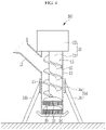
- FIG. 1 is a perspective view schematically illustrating a superabsorbent polymer hydrogel chopping device according to a first exemplary embodiment of the present invention
- FIG. 2 is a cross-sectional view schematically illustrating a major portion of the superabsorbent polymer hydrogel chopping device of FIG. 1
- FIG. 3 is a view of a major portion schematically illustrating a state in which a barrel spiral is formed on an inner wall surface of a barrel body of FIG. 1 .
- a superabsorbent polymer hydrogel chopping device 100 includes a barrel body 10 having a transfer space in which hydrogel is transferred and a discharge portion through which the hydrogel is discharged and which is formed to face a ground direction, a transfer unit 20 installed to the barrel body 10 and configured to transfer the hydrogel in the transfer space 11, a cutter member 30 installed in the barrel body 10 and configured to pulverize the hydrogel transferred by the transfer unit 20, and a perforated plate 40 configured to discharge particles of the hydrogel pulverized by the cutter member 30 to the outside of the barrel body 10.
- the transfer space 11 in which hydrogel is transferred is formed in a length direction, and the barrel body 10 may be installed to be supported on a floor surface.
- An input hopper 13 for introducing hydrogel into the transfer space 11 may be installed at an upper portion of the barrel body 10.
- the input hopper 13 may be installed to protrude from one side of the barrel body 10 and may communicate with the transfer space 11 inside the barrel body 10 so that the hydrogel may be introduced into the transfer space 11.
- One side of the input hopper 13 may be connected to a side surface of the barrel body 10 and the other side thereof may protrude upwardly.
- the input hopper 13 is installed to be inclined upwardly on one side of the barrel body 10, so that an operator may easily inject the hydrogel into the barrel body 10.
- one input hopper 13 is installed and slopingly protruding from the side of the barrel body 10, but the present invention is not necessarily limited thereto, and a modification in which multiple, e.g., two or more, input hoppers may protrude according to a change in an input position and input amount of the hydrogel may also be appropriately applied.
- the barrel body 10 may be provided with a support base 14 for stable support on the floor surface.
- the support base 14 may include a support body 14a installed on a side surface of the barrel body 10 and a plurality of support bars 14b radially protruding from the support body 14a and supported on the floor surface.
- the support base 14 is not necessarily limited to the support body 14a and the support bar 14b, and may be variously modified and applied as a support block type installed on the floor surface and fixed as a fixing unit to fix the barrel body 10 located at the center.
- barrel spiral 15 protrudes from the inside of the barrel body 10.
- the barrel spiral 15 may be formed to have a plurality of spiral shapes protruding from an inner wall surface of the barrel body 10 in the opposite direction to correspond to the spiral shape of the screw member 21.
- the barrel spiral 15 protrudes from the inner wall surface of the barrel body 10, but the present invention is not necessarily limited thereto and the barrel spiral 15 may not be formed.
- the barrel spiral 15 is not necessarily limited to the spiral shape, and variously modified and applied as a concentric band-like projection on the inner wall surface of the barrel body 10 or a spherical or angular projection protruding to correspondto the spiral position of the screw member 21.
- the barrel spiral 15 may stably transfer the hydrogel, as well as an auxiliary action to cut the hydrogel.
- the barrel body 10 may be installed on the support base 14 in a state of being extended in a length long in a direction of gravity action in this exemplary embodiment.
- the barrel body 10 is formed in a cylindrical shape and the discharge portion from which the hydrogel is discharged is installed to face in a ground direction, that is, the direction of gravity, so that a flow direction of the hydrogel may be directed toward the direction of gravity.
- the hydrogel particles may be supplied with a uniform pressure to the perforated plate 40 to be described later. This will be described in more detail while describing the perforated plate 40 below.
- the transfer unit 20 for transferring the hydrogel transferred to the transfer space 11 in the direction of the discharge portion 16 may be installed to the barrel body 10.
- the transfer unit 20 may include a screw member 21 rotatably installed in the transfer space 11 and a driving motor 23 providing a rotational driving force to the screw member 21.
- the screw member 21 may be installed to have a long length in the length direction of the barrel body 10 in the transfer space 11 and may be installed to transfer the hydrogel transferred to the transfer space 11 through the transfer space 11 in the direction of the discharge portion 16.
- the driving motor 23 may be installed above the barrel body 10, and a driving shaft thereof may be connected to an end of the screw member 21 to provide a rotational driving force to the screw member 21.
- the driving motor 23 and the screw member 21 may be installed to transmit a rotational driving force through a speed reducer (not shown).
- the screw member 21 may be installed so that the cutter member 30 rotates together with the rotation of the screw member 21.
- the cutter member 30 is rotatably installed at the position of the discharge portion 16 formed in the barrel body 10 to the screw member 21, and may be installed to appropriately pulverize the hydrogel transferred in the transfer space 11 by the screw member 21.
- the cutter member 30 will be exemplarily described as being installed at one end of the screw member 21.
- the cutter member 30 is not necessarily limited to being installed as one at the end of the screw member 21, and may be appropriately changed and applied to be installed in a plurality of at least two or more corresponding to the amount of transfer of the hydrogel.
- hydrogel pulverized by the cutter member 30 may be extruded and discharged by the perforated plate 40.
- the perforated plate 40 is installed in a position of the discharge portion 16 of the barrel body 10, and a plurality of cut holes may be formed therein. Therefore, the hydrogel pulverized by the cutter member 30 may be pressed and moved inside the barrel body 10 by a pressing force generated by a rotational operation of the screw member 21, and may be stably discharged through the cut holes in the perforated plate 40.
- the perforated plate 40 may be formed of a heat-treated metal and may stably support the pressing force for transferring the hydrogel.
- the barrel body 10 may be vertically installed on the support base 14 to face the direction of gravity, and the pressing force generated according to the rotational operation of the screw member 21 may be uniformly applied to the surface of the perforated plate 40.
- the hydrogel may be uniformly pressed to the surface of the perforated plate 40, while being transferred in the transfer space 11 of the barrel body 10, and thus, the hydrogel may be uniformly chopped, while passing through the cut holes of the perforated plate 40.
- the hydrogel in a state in which the barrel body 10 is installed so that the discharge portion 16 faces the direction of gravity, the hydrogel may be chopped, while passing through the perforated plate 40. Therefore, the hydrogel is chopped in a uniformly pressurized state on the perforated plate 40, so that the hydrogel is uniformly chopped to improve manufacturing quality of the absorbent polymer.
- FIG. 4 is a cross-sectional view of a major portion schematically illustrating a superabsorbent polymer hydrogel chopping device according to a second exemplary embodiment of the present invention.
- the same reference numerals as those in FIGS. 1 to 3 refer to the same or similar members having the same or similar functions. Hereinafter, detailed descriptions of the same reference numerals will be omitted.
- the cutter member 30 and the perforated plate 40 of the superabsorbent polymer hydrogel chopping device 200 according to the second exemplary embodiment of the present invention are installed in plurality on the screw member 21.
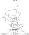
- FIG. 5 is a cross-sectional view of a major portion schematically illustrating a state in which a superabsorbent polymer hydrogel chopping device according to a third exemplary embodiment of the present invention is installed to be inclined to one side
- FIG. 6 is a cross-sectional view of a major portion schematically illustrating a state in which the superabsorbent polymer hydrogel chopping device of FIG. 5 is installed to be inclined to the other side.
- the same reference numerals as those in FIGS. 1 to 4 refer to the same or similar members having the same or similar functions. Hereinafter, detailed descriptions of the same reference numerals will be omitted.
- the barrel body 10 of a hydrogel chopping device 300 may be installed to be inclined in one or the other direction to the support base 14 in a direction staggered with respect to the direction of gravity in the support base 14.
- the barrel body 10 may be installed to be inclined in a direction staggered with respect to the direction of gravity in a state in which it is installed on the support base 14.
- the discharge portion 16 of the barrel body 10 may be installed to be inclined at an obtuse angle or an acute angle with respect to the direction of gravity of the ground.
- the hydrogel may be moved along an internal space of the barrel body 10 and is chopped in the perforated plate 40, so that a stable chopping operation may be performed in a state in which a sudden drop of the hydrogel does not occur.
- FIG. 7 is a perspective view schematically illustrating a superabsorbent polymer hydrogel chopping device according to a fourth exemplary embodiment of the present invention.
- the same reference numerals as in FIGS. 1 to 6 refer to the same or similar members having the same or similar functions. Hereinafter, detailed descriptions of the same reference numerals will be omitted.
- the barrel body 10 of the superabsorbent polymer hydrogel chopping device 400 may be rotatably installed on the support base 314.
- the support base 314 may include a support body 314a annularly installed in a state of being spaced apart from an outer surface of the barrel body 10 from a side surface of the barrel body 10, a plurality of support bars 314b protruding from the support body 14a and supported on the floor surface, and a hinge portion 314c rotatably connecting the support body 14a and the side surfaces of the barrel body 10.
- the support body 14a is installed in an annular shape so that a rotational space is formed between the support body 14a and the outer surface of the barrel body 10, and may be installed to be rotatably connected to the side surface of the barrel body 10 by the hinge portion 314c.
- the barrel body 10 may be installed in a state in which a rotation angle may be changed according to a driving operation of the driving unit 320.
- the driving unit 320 may be installed as a cylinder member transmitting a rotational force to the barrel body 10.
- the driving unit and the cylinder member use the same reference numeral.
- the cylinder member 320 and the rod 321 may be rotatably installed on the barrel body 10. Therefore, a rotation angle of the barrel body 10 installed to the support base 14 is changed according to an operation of the rod 321 of the cylinder member 320, and thus, a smooth chopping operation may be performed by adjusting a transfer angle appropriately to correspond to a transfer amount of the hydrogel.
- FIG. 8 is a cross-sectional view of a major portion schematically illustrating a superabsorbent polymer hydrogel chopping device according to a fifth exemplary embodiment of the present invention
- FIG. 9 is a perspective view schematically illustrating a support portion of FIG. 8
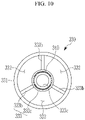
- FIG. 10 is a bottom view schematically illustrating the support portion of FIG. 9 .
- the same reference numerals as those in FIGS. 1 to 7 refer to the same or similar members having the same or similar functions. Hereinafter, detailed descriptions of the same reference numerals will be omitted.
- a transfer unit 420 of a superabsorbent polymer hydrogel chopping device 500 may include a screw member 321 rotatably installed inside the transfer space 11 and moving hydrogel, a driving motor 23 connected to one end of the screw member 321 to provide a rotational driving force, a screw extension portion 323 extending from the other end of the screw member 321 and protruding to the outside of the discharge portion 16, and a support portion 330 installed outside the discharge portion 16 to support the screw extension portion 323.
- the screw member 321 may be installed in the transfer space 11 to transfer the hydrogel in the direction of the discharge portion 16, and one end of the screw member 321 may be connected to the driving motor 23 and the screw extension portion 323 may be installed at the other end of the screw member 321.
- the screw extension portion 323 is installed in an extended state at the other end of the screw member 321, and may be inserted into the support portion 330 so as to be rotationally supported.
- the support portion 330 is installed in a state of protruding to the outside of the discharge portion 16, and is integrally formed with the discharge portion 16 to rotatably support the screw extension portion 323 from the outside of the discharge portion 16.
- the support portion 330 may include a support housing 331 protruding to the outside of the discharge portion 16 and having a discharge space 332 into which pulverized hydrogel particles are discharged and a rotation support portion 333 installed in the support housing 331 and rotatably supporting the screw extension portion 323.
- the support housing 331 protrudes to the outside of the discharge portion 16,and may be integrally formed with the discharge portion 16 to protrude to the outside of the discharge portion 16.
- the support housing 331 is formed in a cylindrical shape and the discharge space 332 through which the pulverized hydrogel particles may be discharged to the outside may be formed therein.
- the rotation support portion 333 is installed inside the support housing 331, and a portion of the screw extension portion 323 may be rotatably inserted therein.
- the screw extension portion 323 is rotatably inserted into the rotation support portion 333, a load of the screw member 321 may be stably supported. Therefore, the screw member 321 may be stably rotatably supported by the rotation support portion 333 in a state of being installed in the ground direction and may be structurally stabilized to improve durability.
- the rotation support portion 333 may include an insertion portion 333a installed in the discharge space 332 of the support housing 331 and rotatably supporting the inserted screw extension portion 323 and a plurality of ribs 333b connecting the insertion portion 333a to an inner wall surface of the support housing 331.
- the insertion portion 333a may be installed inside the support housing 331, and the screw extension portion 323 may be inserted therein and an arrest protrusion 333c may be formed therebelow, so that the screw extension portion 323 may be rotatably supported.
- a bearing member 340 may be installed inside the insertion portion 333a, so that the screw extension portion 323 may be stably rotatably supported.
- a plurality of ribs 333b may be connected between an outer surface of the insertion portion 333a and the inner wall surface of the support housing 331, so that the insertion portion 333a may be stably installed inside the support housing 331.
- the transfer and pulverization process of the hydrogel may be stably performed in a state in which durability is secured.
Landscapes
- Engineering & Computer Science (AREA)
- Mechanical Engineering (AREA)
- Chemical & Material Sciences (AREA)
- Life Sciences & Earth Sciences (AREA)
- Forests & Forestry (AREA)
- Chemical Kinetics & Catalysis (AREA)
- Dispersion Chemistry (AREA)
- Health & Medical Sciences (AREA)
- Medicinal Chemistry (AREA)
- Polymers & Plastics (AREA)
- Organic Chemistry (AREA)
- Food Science & Technology (AREA)
- Addition Polymer Or Copolymer, Post-Treatments, Or Chemical Modifications (AREA)
- Crushing And Pulverization Processes (AREA)
- Disintegrating Or Milling (AREA)
- Perforating, Stamping-Out Or Severing By Means Other Than Cutting (AREA)
Abstract
Description
- This application claims priority to and the benefit of
Korean Patent Application No. 10-2020-0025131 filed in the Korean Intellectual Property Office on February 28, 2020 Korean Patent Application No. 10-2020-0171498 filed in the Korean Intellectual Property Office on December 09, 2020 - The present invention relates to a superabsorbent polymer hydrogel chopping device capable of smoothly chopping a hydrogel.
- A super absorbent polymer (SAP) is a synthetic polymer material that may absorb
water 500 to 1,000 times its own weight, and each developer calls the SAP by other names such as super absorbency material (SAM) or absorbent gel material (AGM), etc. The SAP as described above began to be put to practical use as a sanitary tool, and presently, is widely used as a soil repair agent for gardening, a water-stop material for civil engineering and construction, a sheet for seeding, a freshness maintenance agent in a food distribution field, a material for poultice, etc., as well as for hygiene products such as children's paper diapers. - As a method for preparing the SAP as described above, a method based on inverse suspension polymerization or a method based on aqueous solution polymerization is known. Inverse suspension polymerization is disclosed, for example, in
Japanese Patent Laid-Open Publication Nos. 56-161408 57-158209 57-198714 - A hydrogel or hydrogel polymer obtained through the polymerization reaction as described above is generally pulverized through a drying process and then comes to the market as a powdery product. In order to efficiently perform the drying step as described above, it is important to increase a surface area of the hydrogel polymer as much as possible. Therefore, in order to increase the surface area of the hydrogel polymer before the drying process, a method of simply pulverizing the hydrogel polymer polymerized through thermal polymerization or photopolymerization and increasing the surface area of the hydrogel polymer to be dried may be considered. In order to increase the surface area of the hydrogel polymer as described above, a process of primarily pulverizing the hydrogel polymer after polymerization is disclosed.
- A chopper is mainly used in a primary pulverizing process of the hydrogel.
- The chopper includes a screw for moving the hydrogel, a barrel including a spiral, a cutter blade for cutting the hydrogel, and a perforated plate through which the cut hydrogel is discharged.
- The chopper is installed to be horizontal on the ground, and the hydrogel may be transferred in a horizontal direction of the ground according to an operation of the screw and may be cut in the perforated plate.
- However, it is difficult for the hydrogel to be pressed with a uniform pressure and cut on the perforated plate by an action of gravity, so that the chopping operation is not performed smoothly.
- The present invention has been made in an effort to provide a superabsorbent polymer hydrogel chopping device having advantages of pressing a hydrogel on a perforated plate with a uniform pressure so as to be stably chopped to have a size smaller than a preset size and improving manufacturing quality.
- An exemplary embodiment of the present invention provides a superabsorbent polymer hydrogel chopping device including: a barrel body having a transfer space to which a hydrogel is transferred therein and a discharge portion through which the hydrogel is discharged and which is formed to face a ground direction; a transfer unit installed to the barrel body and configured to transfer the hydrogel in the transfer space; a cutter member installed in the barrel body and configured to pulverize the hydrogel transferred by the transfer unit; and a perforated plate configured to discharge particles of the hydrogel pulverized by the cutter member to the outside of the barrel body.
- The barrel body may be formed to have a length long in a direction of gravity so that the discharge portion is installed to face the direction of gravity.
- An input hopper may be installed on a side surface of the barrel body and configured to input the hydrogel into the transfer space. The input hopper may be installed to be inclined to a side surface of the barrel body.
- The barrel body maybe installed to be supported on a floor surface by a support base.
- The support base may include: a support body installed on side surface of the barrel body; and a plurality of support bars radially protruding from the support body and supported on the floor surface.
- The transfer unit may include: a screw member rotatably installed in an inside of the transfer space and configured to move the hydrogel; and a driving motor configured to provide a rotation driving force to the screw member.
- The cutter member may be rotatably installed to the screw member at a position of the discharge portion.
- The cutter member may be installed in plurality to the screw member.
- The barrel body may be installed to be inclined to the support base in a direction staggered with respect to a direction of gravity in the support base.
- The support base may include: a support body installed in an annular shape and spaced apart from an outer surface of the barrel body on a side surface of the barrel body; a plurality of support bars protruding from the support body and supported on a floor surface; and a hinge portion configured to rotatably connect the support body to a side surface of the barrel body.
- The barrel body may be configured to be rotatably installed to the support base by a driving operation of a driving unit.
- The driving unit may be a cylinder member in which a rod is rotatably connected to a side surface of the barrel body.
- The transfer unit may include: a screw member rotatably installed in the transfer space and configured to move the hydrogel; a driving motor connected to one end of the screw member and configured to provide a rotational driving power; a screw extension portion extending from the other end of the screw member and protruding to the outside of the discharge portion; and a support portion installed on an outer side of the discharge portion and configured to support the screw extension portion.
- The support portion may include: a support housing protruding to the outside of the discharge portion and including a discharge space to which the pulverized hydrogel particles are discharged; and a rotation support portion installed in the support housing and configured to rotatably support the screw extension portion.
- The rotation support portion may include: an insertion portion installed in the discharge space of the support housing and configured to rotatably support the inserted screw extension portion; and a plurality of ribs configured to connect the insertion portion to an inner wall surface of the support housing.
- A bearing member configured to rotatably support the screw extension portion may be installed in the insertion portion.
- According to an exemplary embodiment of the present invention, a perforated plate is installed in a position of a discharge portion to which a hydrogel is discharged in a state in which the discharge portion faces a direction of gravity, and the hydrogel is chopped in a state of being uniformly pressed on the perforated plate, and thus, the hydrogel may be uniformly chopped, thereby improving manufacturing quality of an absorbent polymer.
- According to an exemplary embodiment of the present invention, in a state in which the discharge portion to which the hydrogel is discharged is positioned to be inclined to a direction of a ground, the hydrogel passes through the perforated plate so as to be chopped, thereby performing a stable chopping operation according to a transfer amount of the hydrogel.
-
-
FIG. 1 is a perspective view schematically illustrating a superabsorbent polymer hydrogel chopping device according to a first exemplary embodiment of the present invention. -
FIG. 2 is a cross-sectional view schematically illustrating a major portion of the superabsorbent polymer hydrogel chopping device ofFIG. 1 . -
FIG. 3 is a view of a major portion schematically illustrating a state in which a barrel spiral is formed on an inner wall surface of a barrel body ofFIG. 1 . -
FIG. 4 is a cross-sectional view of a major portion schematically illustrating a superabsorbent polymer hydrogel chopping device according to a second exemplary embodiment of the present invention. -
FIG. 5 is a cross-sectional view of a major portion schematically illustrating a state in which a superabsorbent polymer hydrogel chopping device according to a third exemplary embodiment of the present invention is installed to be inclined to one side. -
FIG. 6 is a cross-sectional view of a major portion schematically illustrating a state in which the superabsorbent polymer hydrogel chopping device ofFIG. 5 is installed to be inclined to the other side. -
FIG. 7 is a perspective view schematically illustrating a superabsorbent polymer hydrogel chopping device according to a fourth exemplary embodiment of the present invention. -
FIG. 8 is a cross-sectional view of a major portion schematically illustrating a superabsorbent polymer hydrogel chopping device according to a fifth exemplary embodiment of the present invention. -
FIG. 9 is a perspective view schematically illustrating a support portion ofFIG. 8 . -
FIG. 10 is a bottom view schematically illustrating the support portion ofFIG. 9 . - Hereinafter, the present invention will be described more fully hereinafter with reference to the accompanying drawings, in which exemplary embodiments of the invention are shown. As those skilled in the art would realize, the described exemplary embodiments may be modified in various different ways, all without departing from the scope of the present invention. The drawings and description are to be regarded as illustrative in nature and not restrictive. Like reference numerals designate like elements throughout the specification.
-
FIG. 1 is a perspective view schematically illustrating a superabsorbent polymer hydrogel chopping device according to a first exemplary embodiment of the present invention,FIG. 2 is a cross-sectional view schematically illustrating a major portion of the superabsorbent polymer hydrogel chopping device ofFIG. 1 , andFIG. 3 is a view of a major portion schematically illustrating a state in which a barrel spiral is formed on an inner wall surface of a barrel body ofFIG. 1 . - As illustrated in
FIGS. 1 to 3 , a superabsorbent polymerhydrogel chopping device 100 according to the first exemplary embodiment of the present invention includes abarrel body 10 having a transfer space in which hydrogel is transferred and a discharge portion through which the hydrogel is discharged and which is formed to face a ground direction, atransfer unit 20 installed to thebarrel body 10 and configured to transfer the hydrogel in thetransfer space 11, acutter member 30 installed in thebarrel body 10 and configured to pulverize the hydrogel transferred by thetransfer unit 20, and aperforated plate 40 configured to discharge particles of the hydrogel pulverized by thecutter member 30 to the outside of thebarrel body 10. - In the
barrel body 10, thetransfer space 11 in which hydrogel is transferred is formed in a length direction, and thebarrel body 10 may be installed to be supported on a floor surface. - An input hopper 13 for introducing hydrogel into the
transfer space 11 may be installed at an upper portion of thebarrel body 10. Theinput hopper 13 may be installed to protrude from one side of thebarrel body 10 and may communicate with thetransfer space 11 inside thebarrel body 10 so that the hydrogel may be introduced into thetransfer space 11. - One side of the
input hopper 13 may be connected to a side surface of thebarrel body 10 and the other side thereof may protrude upwardly. - That is, the
input hopper 13 is installed to be inclined upwardly on one side of thebarrel body 10, so that an operator may easily inject the hydrogel into thebarrel body 10. - It is described, for example, that one
input hopper 13 is installed and slopingly protruding from the side of thebarrel body 10, but the present invention is not necessarily limited thereto, and a modification in which multiple, e.g., two or more, input hoppers may protrude according to a change in an input position and input amount of the hydrogel may also be appropriately applied. - In addition, it is also possible to install the
input hopper 13 such that a position of an opening through which the hydrogel is input has a bellows type in which a diameter and a length of the opening is changed by stages. - The
barrel body 10 may be provided with asupport base 14 for stable support on the floor surface. - The
support base 14 may include asupport body 14a installed on a side surface of thebarrel body 10 and a plurality of support bars 14b radially protruding from thesupport body 14a and supported on the floor surface. - Of course, the
support base 14 is not necessarily limited to thesupport body 14a and thesupport bar 14b, and may be variously modified and applied as a support block type installed on the floor surface and fixed as a fixing unit to fix thebarrel body 10 located at the center. - It is also possible that the
barrel spiral 15 protrudes from the inside of thebarrel body 10. - As shown in
FIG. 3 , thebarrel spiral 15 may be formed to have a plurality of spiral shapes protruding from an inner wall surface of thebarrel body 10 in the opposite direction to correspond to the spiral shape of thescrew member 21. In the present exemplary embodiment, it is described that thebarrel spiral 15 protrudes from the inner wall surface of thebarrel body 10, but the present invention is not necessarily limited thereto and thebarrel spiral 15 may not be formed. - The barrel spiral 15 is not necessarily limited to the spiral shape, and variously modified and applied as a concentric band-like projection on the inner wall surface of the
barrel body 10 or a spherical or angular projection protruding to correspondto the spiral position of thescrew member 21. - As such, since the
barrel spiral 15 protrudes in the inside of thebarrel body 10, thebarrel spiral 15 may stably transfer the hydrogel, as well as an auxiliary action to cut the hydrogel. - Meanwhile, the
barrel body 10 may be installed on thesupport base 14 in a state of being extended in a length long in a direction of gravity action in this exemplary embodiment. - That is, the
barrel body 10 is formed in a cylindrical shape and the discharge portion from which the hydrogel is discharged is installed to face in a ground direction, that is, the direction of gravity, so that a flow direction of the hydrogel may be directed toward the direction of gravity. - Accordingly, since hydrogel particles are moved in the direction of gravity in the
transfer space 11 of thebarrel body 10, the hydrogel particles may be supplied with a uniform pressure to theperforated plate 40 to be described later. This will be described in more detail while describing theperforated plate 40 below. - The
transfer unit 20 for transferring the hydrogel transferred to thetransfer space 11 in the direction of thedischarge portion 16 may be installed to thebarrel body 10. - The
transfer unit 20 may include ascrew member 21 rotatably installed in thetransfer space 11 and a drivingmotor 23 providing a rotational driving force to thescrew member 21. - The
screw member 21 may be installed to have a long length in the length direction of thebarrel body 10 in thetransfer space 11 and may be installed to transfer the hydrogel transferred to thetransfer space 11 through thetransfer space 11 in the direction of thedischarge portion 16. - The driving
motor 23 may be installed above thebarrel body 10, and a driving shaft thereof may be connected to an end of thescrew member 21 to provide a rotational driving force to thescrew member 21. - The driving
motor 23 and thescrew member 21 may be installed to transmit a rotational driving force through a speed reducer (not shown). - Meanwhile, the
screw member 21 may be installed so that thecutter member 30 rotates together with the rotation of thescrew member 21. - The
cutter member 30 is rotatably installed at the position of thedischarge portion 16 formed in thebarrel body 10 to thescrew member 21, and may be installed to appropriately pulverize the hydrogel transferred in thetransfer space 11 by thescrew member 21. - In this exemplary embodiment, the
cutter member 30 will be exemplarily described as being installed at one end of thescrew member 21. However, thecutter member 30 is not necessarily limited to being installed as one at the end of thescrew member 21, and may be appropriately changed and applied to be installed in a plurality of at least two or more corresponding to the amount of transfer of the hydrogel. - Meanwhile, the hydrogel pulverized by the
cutter member 30 may be extruded and discharged by theperforated plate 40. - The
perforated plate 40 is installed in a position of thedischarge portion 16 of thebarrel body 10, and a plurality of cut holes may be formed therein. Therefore, the hydrogel pulverized by thecutter member 30 may be pressed and moved inside thebarrel body 10 by a pressing force generated by a rotational operation of thescrew member 21, and may be stably discharged through the cut holes in theperforated plate 40. - The
perforated plate 40 may be formed of a heat-treated metal and may stably support the pressing force for transferring the hydrogel. - Here, the
barrel body 10 may be vertically installed on thesupport base 14 to face the direction of gravity, and the pressing force generated according to the rotational operation of thescrew member 21 may be uniformly applied to the surface of theperforated plate 40. - Therefore, the hydrogel may be uniformly pressed to the surface of the
perforated plate 40, while being transferred in thetransfer space 11 of thebarrel body 10, and thus, the hydrogel may be uniformly chopped, while passing through the cut holes of theperforated plate 40. - As described above, in the superabsorbent polymer
hydrogel chopping device 100 of this exemplary embodiment, in a state in which thebarrel body 10 is installed so that thedischarge portion 16 faces the direction of gravity, the hydrogel may be chopped, while passing through theperforated plate 40. Therefore, the hydrogel is chopped in a uniformly pressurized state on theperforated plate 40, so that the hydrogel is uniformly chopped to improve manufacturing quality of the absorbent polymer. -
FIG. 4 is a cross-sectional view of a major portion schematically illustrating a superabsorbent polymer hydrogel chopping device according to a second exemplary embodiment of the present invention. The same reference numerals as those inFIGS. 1 to 3 refer to the same or similar members having the same or similar functions. Hereinafter, detailed descriptions of the same reference numerals will be omitted. - As shown in
FIG. 4 , thecutter member 30 and theperforated plate 40 of the superabsorbent polymerhydrogel chopping device 200 according to the second exemplary embodiment of the present invention are installed in plurality on thescrew member 21. - Therefore, it is possible to pulverize the hydrogel using the plurality of
cutter members 30 according to a rotational operation of thescrew member 21, so that it is possible to effectively pulverize the hydrogel. -
FIG. 5 is a cross-sectional view of a major portion schematically illustrating a state in which a superabsorbent polymer hydrogel chopping device according to a third exemplary embodiment of the present invention is installed to be inclined to one side, andFIG. 6 is a cross-sectional view of a major portion schematically illustrating a state in which the superabsorbent polymer hydrogel chopping device ofFIG. 5 is installed to be inclined to the other side. The same reference numerals as those inFIGS. 1 to 4 refer to the same or similar members having the same or similar functions. Hereinafter, detailed descriptions of the same reference numerals will be omitted. - As shown in
FIGS. 5 and6 , thebarrel body 10 of ahydrogel chopping device 300 according to the third exemplary embodiment of the present invention may be installed to be inclined in one or the other direction to thesupport base 14 in a direction staggered with respect to the direction of gravity in thesupport base 14. - The
barrel body 10 may be installed to be inclined in a direction staggered with respect to the direction of gravity in a state in which it is installed on thesupport base 14. - That is, the
discharge portion 16 of thebarrel body 10 may be installed to be inclined at an obtuse angle or an acute angle with respect to the direction of gravity of the ground. - Therefore, the hydrogel may be moved along an internal space of the
barrel body 10 and is chopped in theperforated plate 40, so that a stable chopping operation may be performed in a state in which a sudden drop of the hydrogel does not occur. -
FIG. 7 is a perspective view schematically illustrating a superabsorbent polymer hydrogel chopping device according to a fourth exemplary embodiment of the present invention. The same reference numerals as inFIGS. 1 to 6 refer to the same or similar members having the same or similar functions. Hereinafter, detailed descriptions of the same reference numerals will be omitted. - As shown in
FIG. 7 , thebarrel body 10 of the superabsorbent polymerhydrogel chopping device 400 according to the fifth exemplary embodiment of the present invention may be rotatably installed on the support base 314. - More specifically, the support base 314 may include a
support body 314a annularly installed in a state of being spaced apart from an outer surface of thebarrel body 10 from a side surface of thebarrel body 10, a plurality of support bars 314b protruding from thesupport body 14a and supported on the floor surface, and ahinge portion 314c rotatably connecting thesupport body 14a and the side surfaces of thebarrel body 10. - The
support body 14a is installed in an annular shape so that a rotational space is formed between thesupport body 14a and the outer surface of thebarrel body 10, and may be installed to be rotatably connected to the side surface of thebarrel body 10 by thehinge portion 314c. - The
barrel body 10 may be installed in a state in which a rotation angle may be changed according to a driving operation of thedriving unit 320. - The driving
unit 320 may be installed as a cylinder member transmitting a rotational force to thebarrel body 10. Hereinafter, the driving unit and the cylinder member use the same reference numeral. - The
cylinder member 320 and therod 321 may be rotatably installed on thebarrel body 10. Therefore, a rotation angle of thebarrel body 10 installed to thesupport base 14 is changed according to an operation of therod 321 of thecylinder member 320, and thus, a smooth chopping operation may be performed by adjusting a transfer angle appropriately to correspond to a transfer amount of the hydrogel. -
FIG. 8 is a cross-sectional view of a major portion schematically illustrating a superabsorbent polymer hydrogel chopping device according to a fifth exemplary embodiment of the present invention,FIG. 9 is a perspective view schematically illustrating a support portion ofFIG. 8 , andFIG. 10 is a bottom view schematically illustrating the support portion ofFIG. 9 . The same reference numerals as those inFIGS. 1 to 7 refer to the same or similar members having the same or similar functions. Hereinafter, detailed descriptions of the same reference numerals will be omitted. - As shown in
FIGS. 8 to 10 , atransfer unit 420 of a superabsorbent polymerhydrogel chopping device 500 according to the fifth exemplary embodiment of the present invention may include ascrew member 321 rotatably installed inside thetransfer space 11 and moving hydrogel, a drivingmotor 23 connected to one end of thescrew member 321 to provide a rotational driving force, ascrew extension portion 323 extending from the other end of thescrew member 321 and protruding to the outside of thedischarge portion 16, and asupport portion 330 installed outside thedischarge portion 16 to support thescrew extension portion 323. - The
screw member 321 may be installed in thetransfer space 11 to transfer the hydrogel in the direction of thedischarge portion 16, and one end of thescrew member 321 may be connected to the drivingmotor 23 and thescrew extension portion 323 may be installed at the other end of thescrew member 321. - The
screw extension portion 323 is installed in an extended state at the other end of thescrew member 321, and may be inserted into thesupport portion 330 so as to be rotationally supported. - The
support portion 330 is installed in a state of protruding to the outside of thedischarge portion 16, and is integrally formed with thedischarge portion 16 to rotatably support thescrew extension portion 323 from the outside of thedischarge portion 16. - More specifically, the
support portion 330 may include asupport housing 331 protruding to the outside of thedischarge portion 16 and having adischarge space 332 into which pulverized hydrogel particles are discharged and arotation support portion 333 installed in thesupport housing 331 and rotatably supporting thescrew extension portion 323. - The
support housing 331 protrudes to the outside of thedischarge portion 16,and may be integrally formed with thedischarge portion 16 to protrude to the outside of thedischarge portion 16. Thesupport housing 331 is formed in a cylindrical shape and thedischarge space 332 through which the pulverized hydrogel particles may be discharged to the outside may be formed therein. - The
rotation support portion 333 is installed inside thesupport housing 331, and a portion of thescrew extension portion 323 may be rotatably inserted therein. - As described above, since the
screw extension portion 323 is rotatably inserted into therotation support portion 333, a load of thescrew member 321 may be stably supported. Therefore, thescrew member 321 may be stably rotatably supported by therotation support portion 333 in a state of being installed in the ground direction and may be structurally stabilized to improve durability. - More specifically, the
rotation support portion 333 may include aninsertion portion 333a installed in thedischarge space 332 of thesupport housing 331 and rotatably supporting the insertedscrew extension portion 323 and a plurality ofribs 333b connecting theinsertion portion 333a to an inner wall surface of thesupport housing 331. - The
insertion portion 333a may be installed inside thesupport housing 331, and thescrew extension portion 323 may be inserted therein and anarrest protrusion 333c may be formed therebelow, so that thescrew extension portion 323 may be rotatably supported. - A bearing
member 340 may be installed inside theinsertion portion 333a, so that thescrew extension portion 323 may be stably rotatably supported. - A plurality of
ribs 333b may be connected between an outer surface of theinsertion portion 333a and the inner wall surface of thesupport housing 331, so that theinsertion portion 333a may be stably installed inside thesupport housing 331. - As described above, in the fifth exemplary embodiment, since the load of the
screw member 321 is supported by thesupport portion 330, the transfer and pulverization process of the hydrogel may be stably performed in a state in which durability is secured. - Although preferred exemplary embodiments of the present invention have been described above, the present invention is not limited thereto, and various modifications and variations are possible within the scope of the claims, the detailed description of the invention, and the accompanying drawings. It is natural to fall within the scope.
(Description of reference numerals) 10 first barrel body 11 transfer space 13 input hopper 14 support base 14a support body 14b support bar 15 barrel spiral 16 discharge portion 20, 420 transfer unit 21, 321 screw member 23 driving motor 30 screw member 40. perforated plate 320. driving unit, cylinder member 321. rod 323. screw extension portion 330. support portion 331. support housing 333. rotation support portion 333a. insertion portion 333b. rib 333c. arrest protrusion 340. bearing member
Claims (16)
- A superabsorbent polymer hydrogel chopping device, comprising:a barrel body having a transfer space to which a hydrogel is transferred therein and a discharge portion through which the hydrogel is discharged and which is formed to face a ground direction;a transfer unit installed to the barrel body and configured to transfer the hydrogel in the transfer space;a cutter member installed in the barrel body and configured to pulverize the hydrogel transferred by the transfer unit; anda perforated plate configured to discharge particles of the hydrogel pulverized by the cutter member to the outside of the barrel body.
- The superabsorbent polymer hydrogel chopping device of claim 1, wherein:
the barrel body is formed to have a length long in a direction of gravity so that the discharge portion is installed to face the direction of gravity. - The superabsorbent polymer hydrogel chopping device of claim 2, wherein:an input hopper is installed on a side surface of the barrel body and configured to input the hydrogel into the transfer space, andthe input hopper is installed to be inclined to a side surface of the barrel body.
- The superabsorbent polymer hydrogel chopping device of claim 3, wherein:
the barrel body is installed to be supported on a floor surface by a support base. - The superabsorbent polymer hydrogel chopping device of claim 4, wherein:the support base includesa support body installed on side surface of the barrel body; anda plurality of support bars radially protruding from the support body and supported on the floor surface.
- The superabsorbent polymer hydrogel chopping device of claim 1, wherein:the transfer unit includesa screw member rotatably installed in an inside of the transfer space and configured to move the hydrogel; anda driving motor configured to provide a rotation driving force to the screw member.
- The superabsorbent polymer hydrogel chopping device of claim 6, wherein:
the cutter member is rotatably installed to the screw member at a position of the discharge portion. - The superabsorbent polymer hydrogel chopping device of claim 7, wherein:
the cutter member is installed in plurality to the screw member. - The superabsorbent polymer hydrogel chopping device of claim 3, wherein:
the barrel body is installed to be inclined to the support base in a direction staggered with respect to a direction of gravity in the support base. - The superabsorbent polymer hydrogel chopping device of claim 4, wherein:
the support base includes:a support body installed in an annular shape and spaced apart from an outer surface of the barrel body on a side surface of the barrel body;a plurality of support bars protruding from the support body and supported on a floor surface; anda hinge portion configured to rotatably connect the support body to a side surface of the barrel body. - The superabsorbent polymer hydrogel chopping device of claim 10, wherein:
the barrel body is configured to be rotatably installed to the support base by a driving operation of a driving unit. - The superabsorbent polymer hydrogel chopping device of claim 11, wherein:the driving unitis a cylinder member in which a rod is rotatably connected to a side surface of the barrel body.
- The superabsorbent polymer hydrogel chopping device of claim 7 wherein:
the transfer unit includes:a screw member rotatably installed in the transfer space and configured to move the hydrogel;a driving motor connected to one end of the screw member and configured to provide a rotational driving power;a screw extension portion extending from the other end of the screw member and protruding to the outside of the discharge portion; anda support portion installed on an outer side of the discharge portion and configured to support the screw extension portion. - The superabsorbent polymer hydrogel chopping device of claim 13, wherein:
the support portion includes:a support housing protruding to the outside of the discharge portion and including a discharge space to which the pulverized hydrogel particles are discharged; anda rotation support portion installed in the support housing and configured to rotatably support the screw extension portion. - The superabsorbent polymer hydrogel chopping device of claim 14, wherein:
the rotation support portion includes:an insertion portion installed in the discharge space of the support housing and configured to rotatably support the inserted screw extension portion; anda plurality of ribs configured to connect the insertion portion to an inner wall surface of the support housing. - The superabsorbent polymer hydrogel chopping device of claim 15, wherein:
a bearing member configured to rotatably support the screw extension portion is installed in the insertion portion.
Applications Claiming Priority (3)
| Application Number | Priority Date | Filing Date | Title |
|---|---|---|---|
| KR20200025131 | 2020-02-28 | ||
| KR1020200171498A KR20210110169A (en) | 2020-02-28 | 2020-12-09 | Minute cutting apparatus for super absorbent polymer hydrous gel |
| PCT/KR2021/002085 WO2021172813A1 (en) | 2020-02-28 | 2021-02-18 | Superabsorbent polymer hydrogel chopper |
Publications (3)
| Publication Number | Publication Date |
|---|---|
| EP4011576A1 true EP4011576A1 (en) | 2022-06-15 |
| EP4011576A4 EP4011576A4 (en) | 2022-12-07 |
| EP4011576B1 EP4011576B1 (en) | 2025-10-15 |
Family
ID=77491388
Family Applications (1)
| Application Number | Title | Priority Date | Filing Date |
|---|---|---|---|
| EP21759834.1A Active EP4011576B1 (en) | 2020-02-28 | 2021-02-18 | Superabsorbent polymer hydrogel chopper |
Country Status (6)
| Country | Link |
|---|---|
| US (1) | US12145287B2 (en) |
| EP (1) | EP4011576B1 (en) |
| JP (1) | JP7335052B2 (en) |
| CN (1) | CN114340859A (en) |
| BR (1) | BR112022004700A2 (en) |
| WO (1) | WO2021172813A1 (en) |
Families Citing this family (5)
| Publication number | Priority date | Publication date | Assignee | Title |
|---|---|---|---|---|
| EP3854541B1 (en) | 2020-01-23 | 2024-06-26 | Braun GmbH | Electric beard trimmer |
| EP3854538B1 (en) | 2020-01-23 | 2024-10-16 | Braun GmbH | Electric beard trimmer |
| EP3854540B1 (en) | 2020-01-23 | 2025-03-19 | Braun GmbH | Electric beard trimmer |
| EP3854542B1 (en) | 2020-01-23 | 2023-12-13 | Braun GmbH | Electric beard trimmer |
| KR20230119475A (en) * | 2022-02-07 | 2023-08-16 | 주식회사 엘지화학 | Micronizing apparatus for hydrogel of super absorbent polymer |
Family Cites Families (24)
| Publication number | Priority date | Publication date | Assignee | Title |
|---|---|---|---|---|
| JPS53117666U (en) | 1977-02-25 | 1978-09-19 | ||
| JPS56161408A (en) | 1980-05-19 | 1981-12-11 | Kao Corp | Production of water-absorbing resin |
| JPS57158209A (en) | 1981-03-25 | 1982-09-30 | Kao Corp | Production of bead-form highly water-absorbing polymer |
| JPS57198714A (en) | 1981-05-29 | 1982-12-06 | Sumitomo Chem Co Ltd | Production of hydrogel |
| US4595148A (en) * | 1983-10-03 | 1986-06-17 | Mcculloch Corporation | Machine for comminuting waste material |
| GB2285407A (en) | 1993-12-14 | 1995-07-12 | Kobe Steel Ltd | Apparatus for molding fibrous material containing waste paper |
| KR100210425B1 (en) * | 1997-01-21 | 1999-07-15 | 이준호 | Gel grinding filter of viscous solution |
| JP3415036B2 (en) * | 1998-08-12 | 2003-06-09 | 株式会社日本触媒 | Method for granulating hydrogel crosslinked polymer |
| JP2004330143A (en) | 2003-05-09 | 2004-11-25 | Dai Ichi Kogyo Seiyaku Co Ltd | Method for granulating water-soluble polymer gel |
| IE20030856A1 (en) | 2003-11-14 | 2005-06-15 | Enfer Technology Ltd | Sample homogeniser |
| JP2006346942A (en) * | 2005-06-14 | 2006-12-28 | Refinverse Inc | Resin powder treatment apparatus and resin powder treatment method |
| WO2008038840A1 (en) | 2006-09-29 | 2008-04-03 | Nippon Shokubai Co., Ltd. | Method for producing water absorbent resin particle |
| KR100928690B1 (en) | 2008-08-05 | 2009-11-27 | 원용 이 | Upright Polymer Grinder |
| SA112330882B1 (en) | 2011-09-28 | 2018-01-24 | ارلانكسيو دوتشلاند جى ام بى اتش. | Apparatus for removing volatiles from polymer-containing media |
| EP3520978B1 (en) | 2013-08-28 | 2020-11-04 | Nippon Shokubai Co., Ltd. | Polyacrylic acid (salt)-based water absorbent resin powder |
| CN107936189B (en) | 2013-08-28 | 2021-06-01 | 株式会社日本触媒 | Polyacrylic acid (salt) water-absorbent resin powder and product thereof |
| KR20160020864A (en) | 2014-08-14 | 2016-02-24 | 주식회사 엘지화학 | Superadsorbent resin shredding device |
| KR20160078114A (en) | 2014-12-24 | 2016-07-04 | 한화케미칼 주식회사 | Chopper for manufacturing super absorbent polymer and method for manufacturing super absorbent polymer using the same |
| CN105128166B (en) | 2015-08-28 | 2018-06-19 | 方瑞庭 | The dustless manufacturing method and its device of a kind of aminoplast moulding compound |
| CN206030293U (en) | 2016-08-30 | 2017-03-22 | 陕西国防工业职业技术学院 | Super absorbent polymer resin particles apparatus for producing |
| US11198132B2 (en) | 2017-01-23 | 2021-12-14 | Russell Elbridge Holcomb | Foliage shredder |
| CN208052339U (en) | 2018-04-12 | 2018-11-06 | 邦丽达(福建)新材料股份有限公司 | A kind of particle manufacture equipment for water-absorbing resins production |
| US11975335B2 (en) | 2019-09-19 | 2024-05-07 | Lg Chem, Ltd. | Super absorbent polymer hydrogel shredding device |
| KR20210062459A (en) | 2019-11-21 | 2021-05-31 | 주식회사 엘지화학 | Complex minute cutting apparatus for super absorbent polymer hydrous gel |
-
2021
- 2021-02-18 EP EP21759834.1A patent/EP4011576B1/en active Active
- 2021-02-18 WO PCT/KR2021/002085 patent/WO2021172813A1/en not_active Ceased
- 2021-02-18 BR BR112022004700A patent/BR112022004700A2/en unknown
- 2021-02-18 JP JP2022511325A patent/JP7335052B2/en active Active
- 2021-02-18 US US17/640,606 patent/US12145287B2/en active Active
- 2021-02-18 CN CN202180005089.9A patent/CN114340859A/en active Pending
Also Published As
| Publication number | Publication date |
|---|---|
| BR112022004700A2 (en) | 2022-10-18 |
| EP4011576A4 (en) | 2022-12-07 |
| WO2021172813A1 (en) | 2021-09-02 |
| EP4011576B1 (en) | 2025-10-15 |
| CN114340859A (en) | 2022-04-12 |
| US12145287B2 (en) | 2024-11-19 |
| JP7335052B2 (en) | 2023-08-29 |
| JP2022545021A (en) | 2022-10-24 |
| US20220339811A1 (en) | 2022-10-27 |
Similar Documents
| Publication | Publication Date | Title |
|---|---|---|
| US12145287B2 (en) | Superabsorbent polymer hydrogel chopping device | |
| JP7282438B2 (en) | Water-containing gel shredder for super absorbent polymer | |
| US12251856B2 (en) | Complex minute cutting apparatus for super absorbent polymer hydrogel | |
| KR101114966B1 (en) | Crushing Device for Super Absorbent Resin and Manufacturing Method of Super Absorbent Resin Using the Same | |
| US20030090039A1 (en) | Continuous production of pharmaceutical granulation | |
| JP5442204B2 (en) | Method for producing water absorbent resin particles | |
| JP5883948B2 (en) | Method for producing polyacrylic acid (salt) water-absorbing resin | |
| JP7305254B2 (en) | Water-containing gel shredding device using a pump | |
| RU2680272C1 (en) | Production line of medical food | |
| US20150272078A1 (en) | Method of producing animal litter | |
| KR102500922B1 (en) | A belt dryer arrangement for drying an aqueous polymer gel and comminuting the dry polymer gel to provide dry polymer particles and a process for drying an aqueous polymer gel and comminution of the dry polymer gel to provide dry polymer particles | |
| EP4000736A1 (en) | Superabsorbent polymer hydrogel chopper using pump | |
| KR20250081347A (en) | Hole plate for chopper and chopper provided with the same | |
| KR102468197B1 (en) | Minute cutting apparatus for super absorbent polymer hydrous gel | |
| KR102473251B1 (en) | A belt dryer arrangement for drying the aqueous polymer gel and comminuting the dried polymer gel to form dried polymer particles, and a belt dryer arrangement for drying the aqueous polymer gel and comminuting the dried polymer gel to form dried polymer particles. Way | |
| CN109771285B (en) | Powders and dispensers based on medicinal plant material sources | |
| KR20210110169A (en) | Minute cutting apparatus for super absorbent polymer hydrous gel | |
| RU2707042C2 (en) | Medicated fodders manufacturing method | |
| CN116441002A (en) | Animal manure rubbing crusher | |
| CN119456083A (en) | A grinding and crushing equipment for agricultural product processing | |
| KR20250077810A (en) | Method for producing solid refuse fuel using discarded diapers and system to support the same |
Legal Events
| Date | Code | Title | Description |
|---|---|---|---|
| STAA | Information on the status of an ep patent application or granted ep patent |
Free format text: STATUS: THE INTERNATIONAL PUBLICATION HAS BEEN MADE |
|
| PUAI | Public reference made under article 153(3) epc to a published international application that has entered the european phase |
Free format text: ORIGINAL CODE: 0009012 |
|
| STAA | Information on the status of an ep patent application or granted ep patent |
Free format text: STATUS: REQUEST FOR EXAMINATION WAS MADE |
|
| 17P | Request for examination filed |
Effective date: 20220311 |
|
| AK | Designated contracting states |
Kind code of ref document: A1 Designated state(s): AL AT BE BG CH CY CZ DE DK EE ES FI FR GB GR HR HU IE IS IT LI LT LU LV MC MK MT NL NO PL PT RO RS SE SI SK SM TR |
|
| REG | Reference to a national code |
Ref country code: DE Ref legal event code: R079 Free format text: PREVIOUS MAIN CLASS: B26D0005220000 Ipc: B29B0007420000 Ref country code: DE Ref legal event code: R079 Ref document number: 602021040479 Country of ref document: DE Free format text: PREVIOUS MAIN CLASS: B26D0005220000 Ipc: B29B0007420000 |
|
| A4 | Supplementary search report drawn up and despatched |
Effective date: 20221107 |
|
| RIC1 | Information provided on ipc code assigned before grant |
Ipc: C08J 3/075 20060101ALI20221031BHEP Ipc: C08J 3/12 20060101ALI20221031BHEP Ipc: B29B 9/12 20060101ALI20221031BHEP Ipc: B29B 9/06 20060101ALI20221031BHEP Ipc: B29B 7/60 20060101ALI20221031BHEP Ipc: B29B 7/42 20060101AFI20221031BHEP |
|
| DAV | Request for validation of the european patent (deleted) | ||
| DAX | Request for extension of the european patent (deleted) | ||
| STAA | Information on the status of an ep patent application or granted ep patent |
Free format text: STATUS: EXAMINATION IS IN PROGRESS |
|
| 17Q | First examination report despatched |
Effective date: 20231024 |
|
| GRAP | Despatch of communication of intention to grant a patent |
Free format text: ORIGINAL CODE: EPIDOSNIGR1 |
|
| STAA | Information on the status of an ep patent application or granted ep patent |
Free format text: STATUS: GRANT OF PATENT IS INTENDED |
|
| RIC1 | Information provided on ipc code assigned before grant |
Ipc: B29B 7/42 20060101AFI20250618BHEP Ipc: B29B 7/60 20060101ALI20250618BHEP Ipc: B29B 9/06 20060101ALI20250618BHEP Ipc: B29B 9/12 20060101ALI20250618BHEP Ipc: C08J 3/12 20060101ALI20250618BHEP Ipc: C08J 3/075 20060101ALI20250618BHEP Ipc: B29C 48/14 20190101ALN20250618BHEP Ipc: B29C 48/25 20190101ALN20250618BHEP |
|
| INTG | Intention to grant announced |
Effective date: 20250630 |
|
| GRAS | Grant fee paid |
Free format text: ORIGINAL CODE: EPIDOSNIGR3 |
|
| GRAA | (expected) grant |
Free format text: ORIGINAL CODE: 0009210 |
|
| STAA | Information on the status of an ep patent application or granted ep patent |
Free format text: STATUS: THE PATENT HAS BEEN GRANTED |
|
| AK | Designated contracting states |
Kind code of ref document: B1 Designated state(s): AL AT BE BG CH CY CZ DE DK EE ES FI FR GB GR HR HU IE IS IT LI LT LU LV MC MK MT NL NO PL PT RO RS SE SI SK SM TR |
|
| REG | Reference to a national code |
Ref country code: GB Ref legal event code: FG4D Ref country code: CH Ref legal event code: F10 Free format text: ST27 STATUS EVENT CODE: U-0-0-F10-F00 (AS PROVIDED BY THE NATIONAL OFFICE) Effective date: 20251015 |
|
| REG | Reference to a national code |
Ref country code: IE Ref legal event code: FG4D |
|
| REG | Reference to a national code |
Ref country code: DE Ref legal event code: R096 Ref document number: 602021040479 Country of ref document: DE |
|
| P01 | Opt-out of the competence of the unified patent court (upc) registered |
Free format text: CASE NUMBER: UPC_APP_8930_4011576/2025 Effective date: 20251003 |
|
| REG | Reference to a national code |
Ref country code: NL Ref legal event code: MP Effective date: 20251015 |
|
| REG | Reference to a national code |
Ref country code: AT Ref legal event code: MK05 Ref document number: 1846588 Country of ref document: AT Kind code of ref document: T Effective date: 20251015 |
|
| PG25 | Lapsed in a contracting state [announced via postgrant information from national office to epo] |
Ref country code: NL Free format text: LAPSE BECAUSE OF FAILURE TO SUBMIT A TRANSLATION OF THE DESCRIPTION OR TO PAY THE FEE WITHIN THE PRESCRIBED TIME-LIMIT Effective date: 20251015 |
|
| PGFP | Annual fee paid to national office [announced via postgrant information from national office to epo] |
Ref country code: GB Payment date: 20260122 Year of fee payment: 6 |
|
| PG25 | Lapsed in a contracting state [announced via postgrant information from national office to epo] |
Ref country code: ES Free format text: LAPSE BECAUSE OF FAILURE TO SUBMIT A TRANSLATION OF THE DESCRIPTION OR TO PAY THE FEE WITHIN THE PRESCRIBED TIME-LIMIT Effective date: 20251015 |
|
| REG | Reference to a national code |
Ref country code: LT Ref legal event code: MG9D |
|
| PG25 | Lapsed in a contracting state [announced via postgrant information from national office to epo] |
Ref country code: NO Free format text: LAPSE BECAUSE OF FAILURE TO SUBMIT A TRANSLATION OF THE DESCRIPTION OR TO PAY THE FEE WITHIN THE PRESCRIBED TIME-LIMIT Effective date: 20260115 |
|
| PGFP | Annual fee paid to national office [announced via postgrant information from national office to epo] |
Ref country code: DE Payment date: 20260120 Year of fee payment: 6 |
|
| PG25 | Lapsed in a contracting state [announced via postgrant information from national office to epo] |
Ref country code: AT Free format text: LAPSE BECAUSE OF FAILURE TO SUBMIT A TRANSLATION OF THE DESCRIPTION OR TO PAY THE FEE WITHIN THE PRESCRIBED TIME-LIMIT Effective date: 20251015 Ref country code: HR Free format text: LAPSE BECAUSE OF FAILURE TO SUBMIT A TRANSLATION OF THE DESCRIPTION OR TO PAY THE FEE WITHIN THE PRESCRIBED TIME-LIMIT Effective date: 20251015 Ref country code: FI Free format text: LAPSE BECAUSE OF FAILURE TO SUBMIT A TRANSLATION OF THE DESCRIPTION OR TO PAY THE FEE WITHIN THE PRESCRIBED TIME-LIMIT Effective date: 20251015 |
|
| PGFP | Annual fee paid to national office [announced via postgrant information from national office to epo] |
Ref country code: BE Payment date: 20260121 Year of fee payment: 6 |
|
| PG25 | Lapsed in a contracting state [announced via postgrant information from national office to epo] |
Ref country code: RS Free format text: LAPSE BECAUSE OF FAILURE TO SUBMIT A TRANSLATION OF THE DESCRIPTION OR TO PAY THE FEE WITHIN THE PRESCRIBED TIME-LIMIT Effective date: 20260115 |
|
| PG25 | Lapsed in a contracting state [announced via postgrant information from national office to epo] |
Ref country code: IS Free format text: LAPSE BECAUSE OF FAILURE TO SUBMIT A TRANSLATION OF THE DESCRIPTION OR TO PAY THE FEE WITHIN THE PRESCRIBED TIME-LIMIT Effective date: 20260215 |
|
| PGFP | Annual fee paid to national office [announced via postgrant information from national office to epo] |
Ref country code: FR Payment date: 20260121 Year of fee payment: 6 |
|
| PG25 | Lapsed in a contracting state [announced via postgrant information from national office to epo] |
Ref country code: PT Free format text: LAPSE BECAUSE OF FAILURE TO SUBMIT A TRANSLATION OF THE DESCRIPTION OR TO PAY THE FEE WITHIN THE PRESCRIBED TIME-LIMIT Effective date: 20260216 |
|
| PG25 | Lapsed in a contracting state [announced via postgrant information from national office to epo] |
Ref country code: PL Free format text: LAPSE BECAUSE OF FAILURE TO SUBMIT A TRANSLATION OF THE DESCRIPTION OR TO PAY THE FEE WITHIN THE PRESCRIBED TIME-LIMIT Effective date: 20251015 |
|
| PG25 | Lapsed in a contracting state [announced via postgrant information from national office to epo] |
Ref country code: LV Free format text: LAPSE BECAUSE OF FAILURE TO SUBMIT A TRANSLATION OF THE DESCRIPTION OR TO PAY THE FEE WITHIN THE PRESCRIBED TIME-LIMIT Effective date: 20251015 |
|
| PG25 | Lapsed in a contracting state [announced via postgrant information from national office to epo] |
Ref country code: BG Free format text: LAPSE BECAUSE OF FAILURE TO SUBMIT A TRANSLATION OF THE DESCRIPTION OR TO PAY THE FEE WITHIN THE PRESCRIBED TIME-LIMIT Effective date: 20251015 |