EP4011345A1 - Enclosed patient suite with mounted medical systems - Google Patents
Enclosed patient suite with mounted medical systems Download PDFInfo
- Publication number
- EP4011345A1 EP4011345A1 EP21214474.5A EP21214474A EP4011345A1 EP 4011345 A1 EP4011345 A1 EP 4011345A1 EP 21214474 A EP21214474 A EP 21214474A EP 4011345 A1 EP4011345 A1 EP 4011345A1
- Authority
- EP
- European Patent Office
- Prior art keywords
- suite
- patient
- enclosed
- aircraft
- walls
- Prior art date
- Legal status (The legal status is an assumption and is not a legal conclusion. Google has not performed a legal analysis and makes no representation as to the accuracy of the status listed.)
- Withdrawn
Links
Images









Classifications
-
- A—HUMAN NECESSITIES
- A61—MEDICAL OR VETERINARY SCIENCE; HYGIENE
- A61G—TRANSPORT, PERSONAL CONVEYANCES, OR ACCOMMODATION SPECIALLY ADAPTED FOR PATIENTS OR DISABLED PERSONS; OPERATING TABLES OR CHAIRS; CHAIRS FOR DENTISTRY; FUNERAL DEVICES
- A61G12/00—Accommodation for nursing, e.g. in hospitals, not covered by groups A61G1/00 - A61G11/00, e.g. trolleys for transport of medicaments or food; Prescription lists
- A61G12/002—Supply appliances, e.g. columns for gas, fluid, electricity supply
- A61G12/005—Supply appliances, e.g. columns for gas, fluid, electricity supply mounted on the wall
-
- A—HUMAN NECESSITIES
- A61—MEDICAL OR VETERINARY SCIENCE; HYGIENE
- A61G—TRANSPORT, PERSONAL CONVEYANCES, OR ACCOMMODATION SPECIALLY ADAPTED FOR PATIENTS OR DISABLED PERSONS; OPERATING TABLES OR CHAIRS; CHAIRS FOR DENTISTRY; FUNERAL DEVICES
- A61G10/00—Treatment rooms or enclosures for medical purposes
- A61G10/02—Treatment rooms or enclosures for medical purposes with artificial climate; with means to maintain a desired pressure, e.g. for germ-free rooms
-
- A—HUMAN NECESSITIES
- A61—MEDICAL OR VETERINARY SCIENCE; HYGIENE
- A61G—TRANSPORT, PERSONAL CONVEYANCES, OR ACCOMMODATION SPECIALLY ADAPTED FOR PATIENTS OR DISABLED PERSONS; OPERATING TABLES OR CHAIRS; CHAIRS FOR DENTISTRY; FUNERAL DEVICES
- A61G12/00—Accommodation for nursing, e.g. in hospitals, not covered by groups A61G1/00 - A61G11/00, e.g. trolleys for transport of medicaments or food; Prescription lists
- A61G12/002—Supply appliances, e.g. columns for gas, fluid, electricity supply
- A61G12/007—Supply appliances, e.g. columns for gas, fluid, electricity supply mounted on the floor, e.g. tracks
-
- A—HUMAN NECESSITIES
- A61—MEDICAL OR VETERINARY SCIENCE; HYGIENE
- A61G—TRANSPORT, PERSONAL CONVEYANCES, OR ACCOMMODATION SPECIALLY ADAPTED FOR PATIENTS OR DISABLED PERSONS; OPERATING TABLES OR CHAIRS; CHAIRS FOR DENTISTRY; FUNERAL DEVICES
- A61G2203/00—General characteristics of devices
- A61G2203/10—General characteristics of devices characterised by specific control means, e.g. for adjustment or steering
- A61G2203/20—Displays or monitors
-
- A—HUMAN NECESSITIES
- A61—MEDICAL OR VETERINARY SCIENCE; HYGIENE
- A61G—TRANSPORT, PERSONAL CONVEYANCES, OR ACCOMMODATION SPECIALLY ADAPTED FOR PATIENTS OR DISABLED PERSONS; OPERATING TABLES OR CHAIRS; CHAIRS FOR DENTISTRY; FUNERAL DEVICES
- A61G2210/00—Devices for specific treatment or diagnosis
- A61G2210/70—Devices for specific treatment or diagnosis for cooling
-
- A—HUMAN NECESSITIES
- A61—MEDICAL OR VETERINARY SCIENCE; HYGIENE
- A61G—TRANSPORT, PERSONAL CONVEYANCES, OR ACCOMMODATION SPECIALLY ADAPTED FOR PATIENTS OR DISABLED PERSONS; OPERATING TABLES OR CHAIRS; CHAIRS FOR DENTISTRY; FUNERAL DEVICES
- A61G2220/00—Adaptations of particular transporting means
- A61G2220/10—Aircrafts
-
- B—PERFORMING OPERATIONS; TRANSPORTING
- B64—AIRCRAFT; AVIATION; COSMONAUTICS
- B64D—EQUIPMENT FOR FITTING IN OR TO AIRCRAFT; FLIGHT SUITS; PARACHUTES; ARRANGEMENT OR MOUNTING OF POWER PLANTS OR PROPULSION TRANSMISSIONS IN AIRCRAFT
- B64D11/00—Passenger or crew accommodation; Flight-deck installations not otherwise provided for
- B64D2011/0069—Rest berths, beds or the like
-
- B—PERFORMING OPERATIONS; TRANSPORTING
- B64—AIRCRAFT; AVIATION; COSMONAUTICS
- B64D—EQUIPMENT FOR FITTING IN OR TO AIRCRAFT; FLIGHT SUITS; PARACHUTES; ARRANGEMENT OR MOUNTING OF POWER PLANTS OR PROPULSION TRANSMISSIONS IN AIRCRAFT
- B64D11/00—Passenger or crew accommodation; Flight-deck installations not otherwise provided for
- B64D2011/0069—Rest berths, beds or the like
- B64D2011/0092—Arrangements for mounting stretchers in aircraft cabins
Definitions
- the medical gurneys are limited in features, providing only minimal support for a patient during transfer between medical locations. During the changing of locations, the patient may need to be connected to and/or disconnected from patient monitoring systems at each medical location.
- the medical gurneys may be non-standardized with respect to the various types of medical locations and may be difficult to relocate during transfer between medical locations and/or difficult to secure at the medical locations between transfers.
- the enclosed patient suite may include a patient bed.
- the enclosed patient suite may include a plurality of suite walls.
- the patient bed may be positioned in a patient area defined within the plurality of suite walls.
- the enclosed patient suite may include a plurality of medical systems. At least some of the plurality of medical systems may be mounted to the plurality of suite walls.
- the enclosed patient suite may include a plurality of support members.
- the plurality of support members may be coupled to the plurality of suite walls.
- the enclosed patient suite may include a plurality of wheels. A particular wheel of the plurality of wheels may be coupled to a corresponding support member of the plurality of support members.
- the enclosed patient suite may include a rail brake.
- the rail brake may be configured to engage a floor-mounted rail in a floor of at least one of a cargo hold or a cabin of an aircraft.
- the enclosed patient suite may be dimensioned to fit within the aircraft.
- the enclosed patient suite may include a controller.
- the controller may be coupled to the plurality of medical systems.
- the controller may be configured to receive data from and transmit data to the plurality of medical systems.
- an upper portion of the patient bed may be actuatable between a bed position and at least one raised position.
- At least some of the plurality of wheels may be coupled to the plurality of suite walls.
- At least some of the plurality of support members may be actuatable between a raised position and a lowered position.
- At least some of the plurality of medical systems may be mounted in the patient area in a space underneath the patient bed.
- the plurality of medical systems may include at least one of a refrigeration unit, a sterilizer, a patient monitoring system, a locking tool rack, a plurality of mount locations for medical supplies, or one or more identification tags.
- the enclosed patient suite may include a door.
- the door may be configured to actuate between an open position and a closed position.
- the door may be configured to provide access to the patient area through an opening in the plurality of suite walls.
- the closed position of the door may be located in a cavity defined within the plurality of suite walls.
- the enclosed patient suite may be configured to couple to the aircraft for at least one of power transfer or data transfer.
- the enclosed patient suite may include a battery.
- the enclosed patient suite may include an uninterruptable power supply (UPS).
- the enclosed patient suite may include a power switching system coupled to at least one of the battery, the UPS, or the aircraft.
- the power switching system may be configured to allow the aircraft to charge at least one of the battery or the UPS when the enclosed patient suite is coupled to the aircraft.
- the power switching system may be configured to allow the aircraft to power at least some of the plurality of medical systems when the enclosed patient suite is coupled to the aircraft.
- the power switching system may be configured to switch the battery or the UPS to powering at least some of the plurality of medical systems when the enclosed patient suite is uncoupled from the aircraft.
- the enclosed patient suite may include a patient bed.
- the enclosed patient suite may include a plurality of suite walls.
- the patient bed may be positioned in a patient area defined within the plurality of suite walls.
- the enclosed patient suite may include a plurality of medical systems. At least some of the plurality of medical systems may be mounted to the plurality of suite walls.
- the enclosed patient suite may include a plurality of support members.
- the plurality of support members may be coupled to the plurality of suite walls.
- the enclosed patient suite may include a plurality of wheels. A particular wheel of the plurality of wheels may be coupled to a corresponding support member of the plurality of support members.
- the enclosed patient suite may include a rail brake.
- the rail brake may be configured to engage a floor-mounted rail in a floor of at least one of a cargo hold or a cabin of an aircraft.
- the enclosed patient suite may be dimensioned to fit within the aircraft, a vehicle, and a building.
- the enclosed patient suite may be transferrable between the aircraft and the vehicle at a first time.
- the enclosed patient suite may be transferrable between the aircraft and the building at a second time.
- the enclosed patient suite may include a controller.
- the controller may be coupled to the plurality of medical systems.
- the controller may be configured to receive data from and transmit data to the plurality of medical systems.
- the enclosed patient suite may be configured to couple to the aircraft at a third time for at least one of power transfer or data transfer.
- the enclosed patient suite may be configured to the vehicle at a fourth time for at least one of power transfer or data transfer.
- the enclosed patient suite may be configured to the building at a fifth time for at least one of power transfer or data transfer.
- a letter following a reference numeral is intended to reference an embodiment of the feature or element that may be similar, but not necessarily identical, to a previously described element or feature bearing the same reference numeral (e.g., 1, 1a, 1b).
- reference numeral e.g. 1, 1a, 1b
- Such shorthand notations are used for purposes of convenience only and should not be construed to limit the disclosure in any way unless expressly stated to the contrary.
- any reference to “one embodiment” or “some embodiments” means that a particular element, feature, structure, or characteristic described in connection with the embodiment is included in at least one embodiment disclosed herein.
- the appearances of the phrase “in some embodiments” in various places in the specification are not necessarily all referring to the same embodiment, and embodiments may include one or more of the features expressly described or inherently present herein, or any combination of or sub-combination of two or more such features, along with any other features which may not necessarily be expressly described or inherently present in the instant disclosure.
- FIGS. 1A-10 in general illustrate an enclosed patient suite with mounted medical systems, in accordance with one or more embodiments of the disclosure.
- a patient may need to be transferred between field locations (e.g., areas of conflict, bases, or the like) and hospitals.
- the patient may need to be transferred from the field location via an aircraft.
- the patient may need to be transferred to and/or from the aircraft via a vehicle (e.g., a truck, an ambulance, or the like).
- the patient may need to be connected to and/or disconnected from patient monitoring systems at the medical location.
- the aircraft, the vehicle, and/or the hospital may include medical tools and/or medical devices for stabilizing, analyzing, treating, and/or monitoring the patient during transportation on the medical gurney.
- the aircraft, the vehicle, and/or the hospital may include connections for couplers (e.g., physical couplers, electrical couplers, fluidic couplers, communicative couplers, or the like) configured to attach to the medical tools and/or medical devices for stabilizing, analyzing, treating, and/or monitoring the patient which may accompany the medical gurney.
- couplers e.g., physical couplers, electrical couplers, fluidic couplers, communicative couplers, or the like
- the medical gurneys may be non-standardized with respect to the various types of medical locations and may be difficult to relocate during transfer between medical locations and/or difficult to secure at the medical locations between transfers.
- the medical gurney may need to be insertable and/or removable from the aircraft, and may need to be secured within the aircraft during flight.
- the medical gurney may need to be insertable and/or removable from the vehicle, and may need to be secured within the vehicle during travel.
- the medical gurney may need to be moveable between the vehicle and the aircraft.
- the enclosed patient suite may be insertable, removable, moveable, and/or transportable in an aircraft, a vehicle, and/or a building.
- the enclosed patient suite may include a patient bed.
- the enclosed patient suite may include mounted medical tools and/or medical devices for stabilizing, analyzing, treating, and/or monitoring the patient, which accompany the patient bed within the enclosed patient suite.
- the enclosed patient suite may include connections for couplers (e.g., physical couplers, electrical couplers, fluidic couplers, communicative couplers, or the like) configured to attach to the aircraft, the vehicle, and/or the building with the medical tools and/or medical devices for stabilizing, analyzing, treating, and/or monitoring the patient accompanying the patient bed within the enclosed patient suite.
- couplers e.g., physical couplers, electrical couplers, fluidic couplers, communicative couplers, or the like
- the patient bed may be enclosed for privacy and/or for safety (e.g., safety in instances where exposure to an outside environment may threaten the patient and/or medical personnel treating the patient).
- the enclosed patient suite and/or mounted medical systems of the enclosed patient suite may be configured in accordance with aviation guidelines and/or standards put forth by, but not limited to, the Federal Aviation Administration (FAA), the European Aviation Safety Agency (EASA) or any other flight certification agency or organization; the American National Standards Institute (ANSI), Aeronautical Radio, Incorporated (ARINC), or any other standards setting organization or company; the Radio Technical Commission for Aeronautics (RTCA) or any other guidelines agency or organization; or the like.
- FAA Federal Aviation Administration
- EASA European Aviation Safety Agency
- ARINC Aeronautical Radio, Incorporated
- RTCA Radio Technical Commission for Aeronautics
- both the enclosed patient suite and/or mounted medical systems of the enclosed patient suite may be tested per aviation guidelines and/or standards in the most recent versions of the codes set forth in at least 14 C.F.R. Part 25, AIRWORTHINESS STANDARDS: TRANSPORT CATEGORY AIRPLANES in effect at the time of filing.
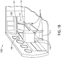
- FIGS. 1A and 1B in general illustrate an aircraft 100, in accordance with one or more embodiments of the disclosure.
- the aircraft 100 may include a cargo hold 102a or cabin 102b.
- the cargo hold 102a or the cabin 102b may include an enclosed patient suite 104.
- enclosed patient suite and variants of the term including, but not limited to, "patient suite,” “enclosed medical suite,” “medical suite,” “suite,” or the like may be considered equivalent, for purposes of the disclosure.
- the suite 104 may include one or more suite walls 106 coupled to a suite floor, and one or more doors 108. It is noted herein the coupling or at least partially installing (e.g., insetting, embedding, or the like) medical tools and/or medical devices in the one or more walls 106 may be considered mounting the medical tools and/or medical devices within the suite 104, for purposes of the disclosure.
- the one or more suite walls 106 may form at least three sides of the suite 104.
- the one or more suite walls 106 may include three suite walls 106 which form three sides of the suite 104 and one or more doors 108 which form a fourth side of the suite 104.
- the one or more suite walls 106 may include four suite walls 106, where three suite walls 106 form three sides of the suite 104 and a fourth suite wall 106 partially forms a fourth side of the suite 104, with one or more doors 108 forming the remainder of the fourth side.
- walls “panels,” “partitions,” “shells,” and “screens” may be configured equivalent, for purposes of the disclosure.
- the one or more doors 108 may be configured to allow access into the suite 104.
- a door 108 may rest on a corresponding track (or set of tracks), and may actuate along the track (e.g., in a sliding motion) between a closed position and an open position.
- the door 108 may slide within a cavity (e.g., cavity 206, as illustrated in at least FIG. 2 ) defined within a suite wall 106 (e.g., is a pocket door), against an exterior surface of a suite wall 106, or an interior surface of a suite wall 106.
- a door 108 may be coupled to a suite wall 106 via one or more hinge assemblies.
- a door 108 may be coupled to a suite wall 106 via one or more interlocking assemblies (e.g., tab and groove assemblies, latch assemblies, snap-fit or interference assemblies, or the like), where the one or more interlocking assemblies may be disassembled to allow for access into the suite 104.
- a door 108 may be configured to draw, roll up, or otherwise collapse when actuating from a closed position to an open position, and vice versa when actuating from the open position to the closed position.
- the suite 104 may not include the one or more doors 108, and that the one or more suite walls 106 may instead leave a gap or opening to allow for access into the suite 104.
- the suite 104 may include a set of wheels 110.
- the set of wheels 110 may include one or more caster wheels and/or one or more fixed wheels.
- the set of wheels 110 may include, but are not limited to, solid plastic wheels, hard foam wheels, solid rubber wheels, solid tubeless pneumatic wheels, tubed pneumatic wheels, or the like.
- the suite 104 may include one or more floor couplers 112 configured to couple to a floor-mounted component 114 within a floor 116 of the cargo hold 102a and/or the cabin 102b of the aircraft 100.
- the one or more floor couplers 112 may include, but are not limited to, a rail brake 112.
- the one or more floor-mounted components 114 may include, but are not limited to, a rail 114. It is noted herein the one or more floor-mounted components 114 may include tracks, brackets, or other floor-mounted components 114.
- the one or more floor couplers 112 may include one or more brake pads 118 configured to engage a surface of the floor-mounted component 114, where the one or more brake pads 118 are manually engaged or disengaged, and/or are engaged or disengaged with one or more mechanical, electromechanical, pneumatic, or hydraulic actuation devices (e.g., assemblies, controls, actuators such as motors, or the like).
- the one or more floor couplers 112 may include feet configured to be inserted within a hole in the floor-mounted component 114.
- the one or more floor couplers 112 may be positioned between wheels of the set of wheels 110 or outside of wheels of the set of wheels 110.
- the suite 104 may include a patient bed 120. It is noted herein "patient bed” and variants of the term including, but not limited to, “bed,” or the like may be considered equivalent, for purposes of the disclosure.
- FIGS. 2-4B in general illustrate example embodiments of the suite 104, in accordance with one or more embodiments of the disclosure.
- the suite 104 may include a number of medical tools and/or medical devices for stabilizing, analyzing, treating, and/or monitoring the patient. It is noted herein the medical tools and/or medical devices as described with respect to at least FIGS. 2-4B may be considered medical systems of the suite 104.
- the suite 104 may include a number of auxiliary components for securing the medical tools and/or medical devices, medical supplies, personal effects of the patient and/or the medical personnel.
- the auxiliary components may include, but are not limited to, storage compartments, trays, shelves, tool racks, or the like.
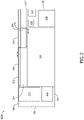
- FIG. 2 a top plan view of an example embodiment of the suite 104 is illustrated, in accordance with one or more embodiments of the disclosure.
- the suite 104 may include a patient area 200.
- the patient area 200 may include an area in which the patient bed 120 is located proximate to the one or more doors 108.
- the patient area 200 may be accessed via an opening 202 within the one or more suite walls 106, where the opening 202 is created by the one or more doors 108 actuating into an open position (e.g., within the cavity 206).
- the opening 202 may lead directly into the patient area 200, or may lead to a pass-through area 204 before entering the patient area 202.
- the pass-through area 204 may be empty space between the surrounding environment and the patient area 200.
- the pass-through area 204 may be of a length, width, and/or depth necessary to accommodate space needed for medical tools, medical devices, and/or auxiliary components either coupled to or at least partially installed in (e.g., inset, embedded, or the like) the one or more suite walls 106 or underneath the patient bed 120.
- the suite 104 may include one or more storage compartments 208.
- the one or more storage compartments 208 may be either coupled to or at least partially installed in (e.g., inset, embedded, or the like) the one or more suite walls 106 or underneath the patient bed 120.
- the one or more storage compartment 208 may be configured to receive and hold medical supplies, medical devices, medical tools, or the like.
- the one or more storage compartments 208 may include one or more safety devices (e.g., air masks, personal floatation devices, or the like).
- the one or more storage compartments 208 may include a storage compartment (e.g., a wardrobe) configured to receive long and/or large items (e.g., passenger amenities needing to be hung, carry-on luggage, or the like) that require an increased space and/or that a passenger may prefer to store in a substantially vertical or upright orientation.
- a storage compartment e.g., a wardrobe
- items e.g., passenger amenities needing to be hung, carry-on luggage, or the like
- the one or more storage compartments 208 may be configured to receive and hold (e.g., contain, secure, or the like) one or more passenger amenities including, but not limited to, paper-printed materials (e.g., magazines, newspapers, pamphlets, or the like), select personal electronic devices (e.g., phones, tablets, phablets, laptops, music devices, digital video disc (DVD) players, handheld gaming consoles or devices, or the like), food products, drink products, or the like.
- paper-printed materials e.g., magazines, newspapers, pamphlets, or the like
- select personal electronic devices e.g., phones, tablets, phablets, laptops, music devices, digital video disc (DVD) players, handheld gaming consoles or devices, or the like
- food products drink products, or the like.
- the one or more storage compartments 208 may include one or more electronic connections for one or more passenger amenities such as, but not limited to, one or more charging ports, one or more charging cables, or the like.
- the one or more storage compartments 208 may include one or more electronic connections in communication with one or more components of the suite 104 such as, but not limited to, one or more display device connection ports, one or more display device connection cables, one or more audio output jacks (e.g., headphone jacks), one or more audio input jacks, or the like.
- one or more display device connection ports such as, but not limited to, one or more display device connection ports, one or more display device connection cables, one or more audio output jacks (e.g., headphone jacks), one or more audio input jacks, or the like.
- the one or more storage compartments 208 may include one or more doors 210.
- a door 210 may rest on a corresponding track (or set of tracks), and may actuate along the track (e.g., in a sliding motion) between a closed position and an open position.
- the door 210 may slide within a cavity 212 defined within the suite wall 106 (e.g., is a pocket door), against an exterior surface of a suite wall 106, or an interior surface of a suite wall 106.
- a door 210 may be coupled to a suite wall 106 via one or more hinge assemblies.
- a door 210 may be coupled to a suite wall 106 via one or more interlocking assemblies (e.g., tab and groove assemblies, latch assemblies, snap-fit or interference assemblies, or the like), where the one or more interlocking assemblies may be disassembled to allow for access into a corresponding storage compartment 208.
- a door 210 may be configured to draw, roll up, or otherwise collapse when actuating from a closed position to an open position, and vice versa when actuating from the open position to the closed position.
- the one or more storage compartments 208 may be accessible from within the suite 104 (e.g., where the one or more doors 210 are directed inward into the patient area 200) or from outside the suite 104 (e.g., where the one or more doors 210 are directed outward into the cargo hold 102a and/or the cabin 102b).
- the suite 104 may include one or more refrigerators or refrigeration units 214.
- the one or more refrigeration units 214 may be configured to store medical supplies (e.g., medicine) needing to be kept in a particular (e.g., cold) environment.
- the one or more refrigeration units 214 may include one or more components (e.g., doors, lids, or the like) configured to allow access into the one or more refrigeration units 214.
- the one or more refrigeration units 214 may be accessible from within the suite 104 (e.g., where the one or more components configured to allow access are directed inward into the patient area 200) or from outside the suite 104 (e.g., where the one or more components configured to allow access are directed outward into the cargo hold 102a and/or the cabin 102b).
- the suite 104 may include one or more sterilizers 216.
- the one or more sterilizers 216 may be configured to store medical supplies (e.g., medicine), medical tools, and/or medical devices needing to be kept in a sterilized environment.
- the one or more sterilizers 216 may be configured to sterilize the medical tools and/or medical devices placed within the one or more sterilizers 216.
- the one or more sterilizers 216 may include, but are not limited to, an autoclave, a glass bead sterilizer, or the like.
- the one or more sterilizers 216 may include one or more components (e.g., doors, lids, or the like) configured to allow access into the one or more sterilizers 216.
- the one or more sterilizers 216 may be accessible from within the suite 104 (e.g., where the one or more components configured to allow access are directed inward into the patient area 200) or from outside the suite 104 (e.g., where the one or more components configured to allow access are directed outward into the cargo hold 102a and/or the cabin 102b).
- the suite 104 may include one or more patient monitoring systems 218.
- the one or more patient monitoring systems 218 may include a controller, with components as described throughout the disclosure.
- the one or more patient monitoring systems 218 may include a user interface, with components as described throughout the disclosure.
- the suite 104 may include a battery 220.
- the battery 220 may be configured to maintain power for medical tools and/or medical devices installed within the suite 104 during transfer between locations (e.g., the field, a vehicle, an aircraft, a hospital, or the like), during power outages, or during general operation.
- the suite 104 may include an uninterruptible power supply (UPS) 222.
- UPS uninterruptible power supply
- the UPS 222 may be configured to provide backup to the battery 220.
- the UPS 222 may be configured to charge the battery 220.
- the UPS 222 may be couplable to the aircraft 100.
- the suite 104 may not need to be coupled to a surrounding power system (e.g., within the aircraft 100, within a vehicle, within a hospital, or the like), allowing for complete mobility of the suite 104. It is noted herein, however, the suite 104 may include connections for couplers (e.g., physical couplers, electrical couplers, fluidic couplers, communicative couplers, or the like) configured to attach to a surrounding power system for purposes of obtaining power and/or data.
- couplers e.g., physical couplers, electrical couplers, fluidic couplers, communicative couplers, or the like
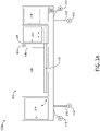
- FIGS. 3A-3G elevation views of example embodiments of the suite 104 are illustrated, in accordance with one or more embodiments of the disclosure.
- the suite 104 may include one or more identification (ID) tags 300.
- the one or more identification (ID) tags 300 may include, but are not limited to, radio frequency identification tags (RFID tags).
- RFID tags radio frequency identification tags
- the one or more ID tags 300 may include Quick Response (QR) codes, handwritten or printed tags, or the like. It is noted herein the one or more ID tags 300 may be tangible objects or may be graphically displayed on a user interface.
- the one or more ID tags 300 may be coupled to an exterior surface (e.g., within an environment of the cargo hold 102a and/or cabin 102b) or an interior surface of the one or more suite walls 106.
- the door 108 is illustrated in an open position in FIG. 3A , and in a closed position in FIG. 3B .
- the door 108 may include a door actuator 302.
- the door actuator 302 may include, but is not limited to, a hole, a handle, a latch, or other device configured to be acted upon by a user to actuate the door 108.
- the door 108 may fully nest within the cavity 206 in the one or more suite walls 106, or may protrude a select amount from within the cavity 206.
- the door actuator 302 may include one or more mechanical, electromechanical, pneumatic, or hydraulic actuation devices (e.g., assemblies, controls, actuators such as motors, or the like).
- any door on the enclosed patient suite 104 may include a door actuator 302 as described above. Therefore, the above description should not be interpreted as a limitation on the scope of the disclosure but merely an illustration.
- the suite 104 may include one or more surfaces 304 at the top of the one or more suite walls 106.
- the one or more surfaces 304 may be used as temporary surfaces (or long-term, depending on whether securing components restraints are installed on the one or more surfaces 304) for access while attending a patient in the patient bed 120.
- the door 210 is illustrated in a closed position in FIG. 3A , and in an open position in FIG. 3B .
- the one or more storage compartments 208 may include one or more shelves 306 fixed in a defined cavity within the one or more storage compartments 208.
- the one or more shelves may be accessible when the door 210 is not in the closed position.
- the patient bed 120 may be rotatable about an axis cross-wise through the patient bed 120 into a position including, but not limited to, an upright or raised position, one or more lounge or reclined positions, and a lie-flat or bed position.
- the patient bed 120 may transition directly between the upright position and the lie-flat or bed position.
- the patient bed 120 may transition through one or more reclined positions between the upright position and the lie-flat or bed position.
- the patient bed 120 may transition into one or more reclined positions in a motion separate from the transition between the upright position and the lie-flat or bed position. Therefore, the above description should not be interpreted as a limitation on the scope of the disclosure but merely an illustration.
- the patient bed 120 is illustrated in a lie-flat or bed position in FIG. 3A , and in a raised position in FIG. 3B .
- the patient bed 120 may be positioned in the lie-flat or bed position and in a raised position at a particular time by an arm 308.
- the arm 308 may support an upper portion 310 of the patient bed 120 at an angle 312.
- the angle may range from 0° to 60°.
- the angle may be selected by engaging a notch 314 of a set of notches 314 with the arm 308, where the set of notches 314 is in a floor portion 316 of the patient area 200.
- the positioning of the upper portion 310 may be selected via a mechanical, electromechanical, pneumatic, or hydraulic actuation device (e.g., assemblies, controls, actuators such as motors, or the like).
- the mechanical, electromechanical, pneumatic, or hydraulic actuation device may include, but is not limited to, a rack-and-pinion assembly (e.g., manually driven or driven with an electric motor and a controller or switch), where the arm 308 is coupled to the rack-and-pinion assembly, in place of the set of notches 314.
- the suite 104 may include one or more support members 318.
- the one or more support members 318 may include one or more legs or primary members, to which at least some of the one or more wheels 110 may couple.
- the suite 104 may include 4, 6, 8, 10, 12 or other number of support members 318, and a corresponding number of wheels 110.
- the one or more primary members may be configured to fold under the suite 104 when not in use.
- the one or more wheels 110 may be configured to fold underneath the suite 104, with the folding of the one or more primary members.
- the one or more primary members 318 may be telescopic, and may be configured to collapse when not in use.
- the one or more wheels 110 may be configured to collapse underneath the suite 104, with the collapsing of the one or more primary members 318.
- the one or more support members 318 may include auxiliary cross-members configured to provide support to the one or more primary members.
- the one or more support members 318 may actuate (e.g., fold or collapse) between a raised position and a lowered position.
- a distance between the raised position and the lowered position may range from 0 inches to 24 inches (0-61 cm).
- the actuation may be caused by one or more mechanical, electromechanical, pneumatic, or hydraulic actuation devices (e.g., assemblies, controls, actuators such as motors, or the like).
- the suite 104 may include indicators (e.g., visual, auditory, graphical, or the like) to indicate when the one or more support members 318 are actuating and/or when the one or more floor couplers 112 are engaged or disengaged from the floor 116.
- the one or more indicators may include, but are not limited to, one or more lights either coupled to or at least partially installed (e.g., inset, embedded, or the like) within the one or more suite walls 106, a housing of the one or more floor couplers 112, or elsewhere on the suite 104.
- the suite 104 may include one or more shelves 320 underneath the one or more suite walls 106.
- the one or more shelves 320 may be coupled to the one or more support members 318.
- the one or more shelves 320 may be configured to receive and contain (e.g., house, be coupled to, or the like) one or more cables, medical supplies, medical tools, and/or medical devices.
- one or more of the medical tools and/or medical devices for stabilizing, analyzing, treating, and/or monitoring the patient may be either coupled to or at least partially installed in (e.g., inset, embedded, or the like) a space underneath the one or more suite walls 106 (e.g., on the one or more shelves 320, in one or more cavities defined within the one or more shelves 320, or the like).
- the coupling or at least partially installing (e.g., insetting, embedding, or the like) medical tools and/or medical devices in the space underneath the one or more suite walls 106 may be considered mounting the medical tools and/or medical devices within the suite 104, for purposes of the disclosure.
- the one or more shelves 320 may be stowable underneath the one or more suite walls 106 prior to movement of the suite 104, to secure any cables, medical supplies, medical tools, and/or medical devices on the one or more shelves 320 against the underside of the one or more suite walls 106.
- the suite 104 may include one or more couplers or brackets 322 configured to hold the one or more shelves in a stowed position.
- one or more wheels 110 may be coupled to the underside of the one or more suite walls 106 directly as a fixed-position wheel 110, as opposed to being coupled via the one or more support members 318.
- the fixed-position wheels 110 may be leading or edge wheels 110.
- one or more wheels 110 may be coupled to the underside of the one or more suite walls 106 via a fixed-length support member 318, as opposed to being coupled via an actuatable support member 318.
- the wheels 110 on fixed-length support members 318 may be center wheels 110.
- FIGS. 4A and 4B elevation views of example embodiments of the suite 104 are illustrated, in accordance with one or more embodiments of the disclosure.
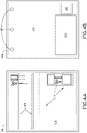
- FIG. 4A illustrates a right elevation view of an interior surface of a first suite wall 106
- FIG. 4B illustrates a right elevation view of an exterior surface of a second suite wall 106 opposite the first suite wall 106.
- a locking tool rack 400 may be either coupled to or at least partially installed in (e.g., inset, embedded, or the like) the suite wall 106.
- the locking tool rack 400 may include, but is not limited to, a posi-locking instrument holder, a twist-lock tool holder, a set of mounting bars, a set of magnetic strips, or the like.
- the size of the one or more sterilizers 216 may be dependent on the size of the one or more refrigeration units 214, as illustrated in FIG. 4A .
- the suite wall 106 may include one or more mount locations 402.
- the one or more mount locations 402 may include, but are not limited to, one or more holes through the suite wall 106 or hooks either coupled to or at least partially installed in (e.g., inset, embedded, or the like) the suite wall 106.
- the one or more holes or hooks may be configured to hold medical supplies (e.g., an intravenous solution (IV) bag, a blood transfer pouch, or the like), a coat or other receive long and/or large item needing to be hung, or the like.
- IV intravenous solution
- the suite 104 may include one or more high-touch areas, or frequent touchpoints in contact with different users, which may have a high potential to transfer microbes (e.g., viruses, pathogens, microorganisms) between the users.
- the high-touch areas may include portions of the suite walls 106 such as, but not limited to, the interior or exterior surfaces of the suite walls 106, or lead edges of the suite walls 106 proximate to the opening 202 of the suite 104 providing access to the patient area 200 from the cargo hold 102a and/or the cabin 102b.
- the high-touch areas may include the various components installed within the suite 104 as listed throughout the disclosure.
- the one or more high-touch areas may be fabricated from an easy-to-clean material and/or may be protected with coatings.
- the one or more high-touch areas may be protected with coatings (e.g., antimicrobial, antiviral, antibacterial, or the like) configured to prevent the transfer of microbes.
- coatings e.g., antimicrobial, antiviral, antibacterial, or the like
- the coatings may be in addition to or instead of disinfection of the high-touch areas during regular cleanings, fogging, and/or cleaning of the suite 104.
- the suite 104 may include one or more stowable seats (e.g., flight attendant seats or other stowable seats) coupled to the suite 104.
- stowable seats e.g., flight attendant seats or other stowable seats
- the stowable seat may be translatable (e.g., trackable or slidable).
- the stowable seat may be rotatable about an axis cross-wise through the stowable seat into a position including, but not limited to, an upright or raised position, one or more lounge or reclined positions, and a lie-flat or bed position.
- the stowable seat may transition directly between the upright position and the lie-flat or bed position.
- the stowable seat may transition through one or more reclined positions between the upright position and the lie-flat or bed position.
- the stowable seat may transition into one or more reclined positions in a motion separate from the transition between the upright position and the lie-flat or bed position. Therefore, the above description should not be interpreted as a limitation on the scope of the disclosure but merely an illustration.
- the stowable seat may be rotatable about an axis (e.g., swivelable).
- the stowable seat may be fully positionable between the outer limits of motion as defined by one or more components of the suite 104.
- an upright or raised position may be considered a taxi, takeoff, or landing (TTOL) position during select stages of flight (though the upright or raised position is not limited to use during the select stages of flight as the TTOL position, but also may be used at any point during the flight), for purposes of the present disclosure.
- TTOL taxi, takeoff, or landing
- any position that does not meet the above-defined requirements of the TTOL position may be considered a non-TTOL position, for purposes of the present disclosure.
- the stowable seat may be actuatable (e.g., translatable and/or rotatable) from the TTOL position to a non-TTOL position, and/or vice versa. Further, it is noted herein the stowable seat may be capable of a fully upright or raised position, and that the TTOL position may have a more reclined seat back cushion and a more angled upward seat pan cushion as compared to the fully upright or raised position. Therefore, the above description should not be interpreted as a limitation on the present disclosure but merely an illustration.
- the stowable seat may be configured to avoid contact with the one or more components of the suite 104 when transitioning between positions (e.g., between the upright or raised position and the lie-flat or bed position).
- the embodiments of the disclosure related to the placement of medical supplies, medical tools, and/or medical devices within the enclosed patient suite 104 are provided only as example embodiments, and that the medical supplies, medical tools, and/or medical devices may be located anywhere within the enclosed patient suite 104 as allowed by the dimensions of the medical supplies, medical tools, and/or medical devices. Therefore, the above description should not be interpreted as a limitation on the scope of the disclosure but merely an illustration.
- the enclosed patient suite 104 and the included medical tools, medical devices, and other components installed within the enclosed patient suite 104 may be moveable as a single, self-contained unit between environments. Being a single, self-contained unit may allow for all necessary medical systems for stabilizing, analyzing, treating, and/or monitoring a patient being transported in the enclosed patient suite 104. Although the capability may be included within the enclosed patient suite 104, the enclosed patient suite 104 may be able to operate without connecting to any surrounding systems and/or may be able to move without disconnecting any patient-supporting systems.
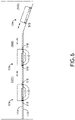
- FIGS. 5A-8 in general illustrate movement of the enclosed patient suite 104 through environments, in accordance with one or more embodiments throughout the disclosure.
- the suite 104 is not limited to the aviation environment (e.g., the aircraft 100) and/or the aircraft components within the aviation environment (e.g., the cargo hold 102a, the cabin 102b, or the like).
- the suite 104 may be configured for any type of vehicle known in the art.
- the vehicle may be any air, space, land, or water-based personal equipment or vehicle; any air, space, land, or water-based commercial equipment or vehicle; any air, space, land, or water-based military equipment or vehicle known in the art.
- the vehicle may include a truck or an ambulance.
- the suite 104 may be configured for commercial or industrial use in either a home or a business (e.g., within a hospital).
- the suite 104 may be transferred from the aircraft 100.
- the suite 104 may be in the aircraft 100. It is noted herein the suite 104 may be coupled to the aircraft 100 for at least one of power transfer or data transfer at the time 500.
- the suite 104 may be unloaded down a ramp 502 of the aircraft 100.
- the suite 104 may be transported to a vehicle 522 (e.g., an ambulance, a truck, or the like).
- the suite 104 may be loaded into the vehicle 522.
- a vehicle 522 may include a floor 532 upon which the suite 104 may be loaded.
- the suite 104 may be coupled to the vehicle 522 for at least one of power transfer or data transfer at the time 530.
- the suite 104 may be transferred from the vehicle 522.
- the suite 104 may be in the vehicle 522. It is noted herein the suite 104 may be coupled to the vehicle 522 for at least one of power transfer or data transfer at the time 540.
- the suite 104 may be unloaded from the vehicle 522.
- the suite 104 may be transported to a building 562 (e.g., a hospital, or the like).
- the suite 104 may be positioned at a designated location within the building 562. It is noted herein the suite 104 may be coupled to the building 562 for at least one of power transfer or data transfer at the time 570.
- the suite 104 may be coupled to a floor-mounted component 114 in the floor 116 of the aircraft 100 with the one or more couplers 112 (e.g., rail brake, feet, or the like)
- the suite 104 may be uncoupled from the floor-mounted component 114 and be transported down the ramp 502.
- the one or more couplers 112 may slide off the rail after the suite 104 is uncoupled while being moved to exit the aircraft 100.
- only one suite 104 is illustrated as being coupled to the floor-mounted component 114 at the time 500, it is noted herein multiple suites 104 may be installed on a single floor-mounted component 114.
- FIG. 7A-7E details of the motion of the suite 104 between times 520 and 530 are illustrated.
- an outside fixed position wheel 110 may come into contact with the floor 532 of the vehicle 522, and an adjacent support member 318 with wheel 110 may be actuated to raise the wheel 110 from a ground height to a floor 532 height.
- the raised wheel 110 coupled to the actuatable support member 318 may come into contact with the floor 532 of the vehicle 522, allowing the suite 104 to further move into the vehicle 522.
- a fixed-length support member 318 with wheel 110 may come into contact with the floor 532 of the vehicle 522 and the suite 104 may further move into the vehicle 522, effectively shifting the bulk of the weight onto the floor 532 of the vehicle 522 (as opposed to the ground outside the vehicle 522), and a second support member 422 with wheel 110 may be actuated to raise the wheel 110 from the ground height to the floor 532 height.
- fixed position wheel 110 and/or the fixed-length support member 318 with wheel 110 may be replaced with an actuatable support member 318 with wheel 110.
- the suite 104 may include a coupling assembly configured to hold the suite 104 in the vehicle 522.
- the coupling assembly may include an attach point 800 (e.g., hook or eye ring, component of an interlocking assembly, or the like) on the suite 104 (e.g., on the housing of a coupler 112) and an attach point 802 (e.g., hook or eye ring, component of an interlocking assembly, or the like) in the floor 532 of the vehicle 522, where the attach point 800 and the attach point 802 may be coupled.
- a rope or strap 804 may pass through the attach point 800 and the attach point 802.
- a bar or linkage 804 may couple to the attach point 800 and the attach point 802.
- FIGS. 5A-8 may be reversed (or at least performed in a different order) to remove the suite 104 from the building 562, to remove the suite 104 from the vehicle 522, and/or load the suite 104 onto the aircraft 100.
- the movement of the suite 104 between the aircraft 100 and the vehicle 522 and/or the movement of the suite 104 between the vehicle 522 and the building 562 may include more or fewer steps. Therefore, the above description should not be interpreted as a limitation on the scope of the disclosure but merely an illustration.
- the one or more support members 318 being in the raised position may actuate the corresponding wheels 110 closer to the underside of the one or more suite walls 106, decreasing a distance between an underside of the one or more suite walls 106 and a floor of the aircraft 100 (e.g., the floor 116), the vehicle 522 (e.g., the floor 532), or the building 562.
- the one or more support members 318 being in the lowered position may actuate the corresponding wheels 110 farther from the underside of the one or more suite walls 106, increasing a distance between an underside of the one or more suite walls 106 and a floor of an aircraft, vehicle, or building.
- the embodiments of the disclosure related to the dimensions of the enclosed patient suite 104 and/or of components installed within the enclosed patient suite 104 are provided only as example embodiments.
- the enclosed gurney suite may be dimensioned based on a standardized layout for insertion, removal, and transport within any of a number of aircraft cargo holds 102a or aircraft cabins 102b of the aircraft 100, the vehicle 522, and/or the building 562.
- the suite 104 may be dimensioned to fit within standard building doors, standard ambulance doors, standard aircraft doors or loading ramps, or the like. Therefore, the above description should not be interpreted as a limitation on the scope of the disclosure but merely an illustration.
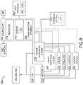
- FIG. 9 illustrates a simplified schematic or block diagram of the enclosed patient suite 104, in accordance with one or more embodiments of the disclosure. It is noted herein the solid connection lines may represent power transfer and the broken connection lines may represent data transfer in FIG. 9 .
- the UPS 222 may be coupled to the battery 220.
- the UPS 222 may be coupled to one or more of the aircraft 100, a vehicle 522, or a building 562 via connections for couplers (e.g., physical couplers, electrical couplers, fluidic couplers, communicative couplers, or the like) configured to attach to a surrounding power system for purposes of obtaining power and/or data.
- couplers e.g., physical couplers, electrical couplers, fluidic couplers, communicative couplers, or the like
- the coupler may include a 120V wall plug.
- the suite 104 may include a power switching system 900.
- the power switching system 900 may determine which power source powers the medical systems in the suite 104 at a given time. For instance, the power switching system 900 may allow the external surrounding power system to charge the battery 220 and/or the UPS 222 when the suite 104 is coupled to the aircraft 100, the vehicle 522 or the building 562. In addition, the power switching system 900 may allow the external surrounding power system to power medical systems of the suite 104 when the suite 104 is coupled to the aircraft 100, the vehicle 522 or the building 562. Further, the power switching system 900 may switch the battery 220 to power medical systems of the suite 104 when the suite 104 is uncoupled from the aircraft 100, the vehicle 522 or the building 562. Further, the power switching system 900 may switch the UPS 222 to power medical systems of the suite 104 when the battery 220 fails or is depleted.
- the battery 220, the power switching system 900, and the external surrounding power system may each be coupled to the one or more refrigeration units 214, the one or more sterilizers 216, the patient monitoring system 218, an oxygen system 902, lighting 904 within the suite 104, and/or a controller 906, depending on the power switching system 900.
- the lighting 904 may be either coupled to or at least partially installed in (e.g., inset, embedded, or the like) the one or more suite walls 106.
- the controller 906 may be coupled to a network 908, one or more hydraulic systems 910 including the one or more support members 318 (e.g., along with the power switching system 900), and/or the ID tags 300.
- the controller 906 may include one or more processors 912.
- the controller 906 may include memory 914, and the one or more processors 912 may be configured to execute a set of program instructions 916 stored in memory 914, the set of program instructions 916 being configured to cause the one or more processors 912 to carry out various steps and processes of the present disclosure.
- the controller 906 may include one or more communication interfaces 918 configured to couple to at least the network 908.
- the network 908 may include components configured to connect via a wireline (e.g., copper wire, fiber optic cable, and the like) or wireless connection (e.g., RF coupling, IR coupling, data network communication (e.g., WiFi, WiMax, 3G, 4G, 4G LTE, 5G, Bluetooth, and the like) for remote medical input including the transmitting and receiving of medical data and/or medical instructions.
- a wireline e.g., copper wire, fiber optic cable, and the like
- wireless connection e.g., RF coupling, IR coupling, data network communication (e.g., WiFi, WiMax, 3G, 4G, 4G LTE, 5G, Bluetooth, and the like) for remote medical input including the transmitting and receiving of medical data and/or medical instructions.
- data network communication e.g., WiFi, WiMax, 3G, 4G, 4G LTE, 5G
- the one or more processors 912 may include any one or more processing elements known in the art. In this sense, the one or more processors 912 may include any microprocessor-type device configured to execute software algorithms and/or instructions.
- the one or more processors 912 may consist of a desktop computer, mainframe computer system, workstation, image computer, parallel processor, or other computer system (e.g., networked computer) configured to execute a program configured to operate the suite 104, as described throughout the present disclosure. It should be recognized that the steps described throughout the present disclosure may be carried out by a single computer system or, alternatively, multiple computer systems. Furthermore, it should be recognized that the steps described throughout the present disclosure may be carried out on any one or more of the one or more processors 912.
- processor may be broadly defined to encompass any device having one or more processing elements, which execute program instructions from memory 914.
- different subsystems of the suite 104 e.g., the patient monitoring system 218, may include processor or logic elements suitable for carrying out at least a portion of the steps described throughout the present disclosure. Therefore, the above description should not be interpreted as a limitation on the present disclosure but merely an illustration.
- the memory 914 may include any storage medium known in the art suitable for storing program instructions executable by the associated one or more processors 912 and the data received/generated by the suite 104.
- the memory 914 may include a non-transitory memory medium.
- the memory 914 may include, but is not limited to, a read-only memory (ROM), a random-access memory (RAM), a magnetic or optical memory device (e.g., disk), a magnetic tape, a solid-state drive and the like.
- ROM read-only memory
- RAM random-access memory
- magnetic or optical memory device e.g., disk
- magnetic tape e.g., a magnetic tape
- solid-state drive e.g., solid-state drive
- memory 914 may be housed in a common controller housing with the one or more processors 912.
- the memory 914 may be located remotely with respect to the physical location of the processors 912 and controller 906.
- the memory 914 may maintain program instructions for causing the one or more processors 912
- the suite 104 may include a user interface 920 communicatively coupled to the controller 906.
- the user interface 920 may include, but is not limited to, one or more desktops, tablets, smartphones, smart watches, or the like.
- the user interface 920 may include one or more displays 922 used to display data of the suite 104 to a user.
- the user interface 920 may include one or more user input devices 924 used to interact with the one or more displays 922 and/or components coupled to the user interface 920 either directly or indirectly (e.g., via the controller 906).
- the one or more displays 922 of the user interface 920 may include any display known in the art.
- the display may include, but is not limited to, a liquid crystal display (LCD), an organic light-emitting diode (OLED) based display, or a CRT display.
- LCD liquid crystal display
- OLED organic light-emitting diode
- CRT CRT display
- a user may input selections and/or instructions responsive to data displayed to the user via the one or more user input devices 924 of the user interface 920.
- the one or more user input devices 924 may include one or more toggles, switches, knobs, or other user input devices.
- FIG. 10 illustrates a simplified block diagram of the enclosed patient suite 104, in accordance with one or more embodiments of the disclosure.
- the suite 104 may include a canopy 1000.
- the canopy 1000 may be fabricated from a rigid material (e.g., metal, plastic, or the like) and configured to retain its shape and/or size.
- the canopy 1000 may be fabricated from a non-rigid material (e.g., fabric, mesh, netting, or the like) and configured to be drawable, foldable, collapsible, or the like.
- the canopy 1000 may be integrated with the one or more suite walls 106, or may be attachable to the one or more suite walls 106 and/or the one or more doors 108.
- the canopy 1000 may be attachable via interlocking assemblies configured to allow for a quick release of the canopy 1000 from the one or more suite walls 106 (e.g., tab and groove assemblies, latch assemblies, snap-fit or interference assemblies, or the like), and/or fasteners (e.g., fasteners such as washers, threaded nuts, bushings, spacers, or the like).
- the canopy 1000 may be removed and stored in the aircraft 100 when not required to enclose the patient for privacy and/or for safety (e.g., safety in instances where exposure to an outside environment may threaten the patient and/or medical personnel treating the patient).
- a gap between the canopy 1000 and the one or more suite walls 106 may be filled in with a filler component fabricated from a solid soft material (e.g., a foam block or shield, a rubber block or shield, or the like), a solid hard material (e.g., a plastic block or shield, a metal block or shield, or the like), a fluidic hardening material (e.g., caulk or other sealing compound), or the like.
- a filler component fabricated from a solid soft material (e.g., a foam block or shield, a rubber block or shield, or the like), a solid hard material (e.g., a plastic block or shield, a metal block or shield, or the like), a fluidic hardening material (e.g., ca
- the suite 104 may include a dome canopy 1000, a flat canopy 1000 (e.g., a ceiling), or a pitched canopy 1000 (e.g., a canopy 1000 that comes to a point at its height). It is noted herein, however, the suite 104 may include extra-high walls 106, such that the canopy 1000 does not form part of the sides of the suite 104.
- the suite 104 may include one or more mount points 1002 for the canopy 1000.
- components of one or more interlocking assemblies e.g., tab and groove assemblies, latch assemblies, snap-fit or interference assemblies, or the like
- the suite 104 may include one or more mount points 1002 for the canopy 1000.
- components of one or more interlocking assemblies e.g., tab and groove assemblies, latch assemblies, snap-fit or interference assemblies, or the like
- mount points 1002 for the canopy 1000.
- interlocking assemblies e.g., tab and groove assemblies, latch assemblies, snap-fit or interference assemblies, or the like
- the suite 104 may include an upper door 1004.
- the upper door 1004 may be a portion of the canopy 1000 coupled to the door 108 when the canopy 1000 is coupled to the one or more suite walls 106.
- the upper door 1004 may be integrated with the door 108.
- the upper door 1004 may be stowable against a surface (e.g., exterior surface or interior surface) of the door 108, or may be stowable in a cavity defined within the door 108, when the canopy 1000 is not attached to or integrated with the one or more suite walls 106.
- the upper door 1004 may be configured to actuate independently of the door 108 and/or may be configured to actuate with an actuation of the door 108.
- a portion 1006 of the upper door 1004 may be open to allow for viewing into the patient area 200, although the door 108 may be in the closed position.
- the portion 1006 may be a cut-out within the upper door 1004.
- the portion 1006 may be closeable (e.g., with a door, screen, curtain, or the like) for privacy and/or for safety (e.g., safety in instances where exposure to an outside environment may threaten the patient and/or medical personnel treating the patient).
- the lighting 904 may be either coupled to or at least partially installed in (e.g., inset, embedded, or the like) the canopy 1000.
- portions of the canopy 1000 e.g., exterior or interior surfaces
- the enclosed patient suite 104 with mounted medical systems may be insertable, removable, moveable, and/or transportable in an aircraft 100, a vehicle 522 (e.g., an ambulance, or the like), and/or a building 562 (e.g., a hospital, or the like).
- the enclosed patient suite 104 may include the patient bed 120.
- the enclosed patient suite 104 may include mounted medical tools and/or medical devices 214, 216, 218, 220, 222, 300, 400 for stabilizing, analyzing, treating, and/or monitoring the patient, which accompany the patient bed 120 within the enclosed patient suite 104.
- the enclosed patient suite 104 may include connections for couplers (e.g., physical couplers, electrical couplers, fluidic couplers, communicative couplers, or the like) configured to attach to the aircraft 100, the vehicle 522, and/or the building 562 with the medical tools and/or medical devices 214, 216, 218, 220, 222, 300, 400 for stabilizing, analyzing, treating, and/or monitoring the patient accompanying the patient bed 120 within the enclosed patient suite 104.
- the patient bed 120 may be enclosed for privacy and/or for safety (e.g., safety in instances where exposure to an outside environment may threaten the patient and/or medical personnel treating the patient).
Landscapes
- Health & Medical Sciences (AREA)
- Life Sciences & Earth Sciences (AREA)
- Animal Behavior & Ethology (AREA)
- General Health & Medical Sciences (AREA)
- Public Health (AREA)
- Veterinary Medicine (AREA)
- Nursing (AREA)
- Pulmonology (AREA)
- Accommodation For Nursing Or Treatment Tables (AREA)
- Engineering & Computer Science (AREA)
- Aviation & Aerospace Engineering (AREA)
Abstract
Description
- Current medical gurneys are limited in features, providing only minimal support for a patient during transfer between medical locations. During the changing of locations, the patient may need to be connected to and/or disconnected from patient monitoring systems at each medical location. The medical gurneys may be non-standardized with respect to the various types of medical locations and may be difficult to relocate during transfer between medical locations and/or difficult to secure at the medical locations between transfers.
- An enclosed patient suite is disclosed, in accordance with one or more embodiments of the disclosure. The enclosed patient suite may include a patient bed. The enclosed patient suite may include a plurality of suite walls. The patient bed may be positioned in a patient area defined within the plurality of suite walls. The enclosed patient suite may include a plurality of medical systems. At least some of the plurality of medical systems may be mounted to the plurality of suite walls. The enclosed patient suite may include a plurality of support members. The plurality of support members may be coupled to the plurality of suite walls. The enclosed patient suite may include a plurality of wheels. A particular wheel of the plurality of wheels may be coupled to a corresponding support member of the plurality of support members. The enclosed patient suite may include a rail brake. The rail brake may be configured to engage a floor-mounted rail in a floor of at least one of a cargo hold or a cabin of an aircraft. The enclosed patient suite may be dimensioned to fit within the aircraft. The enclosed patient suite may include a controller. The controller may be coupled to the plurality of medical systems. The controller may be configured to receive data from and transmit data to the plurality of medical systems.
- In some embodiments, an upper portion of the patient bed may be actuatable between a bed position and at least one raised position.
- In some embodiments, at least some of the plurality of wheels may be coupled to the plurality of suite walls.
- In some embodiments, at least some of the plurality of support members may be actuatable between a raised position and a lowered position.
- In some embodiments, at least some of the plurality of medical systems may be mounted in the patient area in a space underneath the patient bed.
- In some embodiments, the plurality of medical systems may include at least one of a refrigeration unit, a sterilizer, a patient monitoring system, a locking tool rack, a plurality of mount locations for medical supplies, or one or more identification tags.
- In some embodiments, the enclosed patient suite may include a door. The door may be configured to actuate between an open position and a closed position. The door may be configured to provide access to the patient area through an opening in the plurality of suite walls.
- In some embodiments, the closed position of the door may be located in a cavity defined within the plurality of suite walls.
- In some embodiments, the enclosed patient suite may be configured to couple to the aircraft for at least one of power transfer or data transfer.
- In some embodiments, the enclosed patient suite may include a battery. The enclosed patient suite may include an uninterruptable power supply (UPS). The enclosed patient suite may include a power switching system coupled to at least one of the battery, the UPS, or the aircraft.
- In some embodiments, the power switching system may be configured to allow the aircraft to charge at least one of the battery or the UPS when the enclosed patient suite is coupled to the aircraft.
- In some embodiments, the power switching system may be configured to allow the aircraft to power at least some of the plurality of medical systems when the enclosed patient suite is coupled to the aircraft.
- In some embodiments, the power switching system may be configured to switch the battery or the UPS to powering at least some of the plurality of medical systems when the enclosed patient suite is uncoupled from the aircraft.
- An enclosed patient suite is disclosed, in accordance with one or more embodiments of the disclosure. The enclosed patient suite may include a patient bed. The enclosed patient suite may include a plurality of suite walls. The patient bed may be positioned in a patient area defined within the plurality of suite walls. The enclosed patient suite may include a plurality of medical systems. At least some of the plurality of medical systems may be mounted to the plurality of suite walls. The enclosed patient suite may include a plurality of support members. The plurality of support members may be coupled to the plurality of suite walls. The enclosed patient suite may include a plurality of wheels. A particular wheel of the plurality of wheels may be coupled to a corresponding support member of the plurality of support members. The enclosed patient suite may include a rail brake. The rail brake may be configured to engage a floor-mounted rail in a floor of at least one of a cargo hold or a cabin of an aircraft. The enclosed patient suite may be dimensioned to fit within the aircraft, a vehicle, and a building. The enclosed patient suite may be transferrable between the aircraft and the vehicle at a first time. The enclosed patient suite may be transferrable between the aircraft and the building at a second time. The enclosed patient suite may include a controller. The controller may be coupled to the plurality of medical systems. The controller may be configured to receive data from and transmit data to the plurality of medical systems.
- In some embodiments, the enclosed patient suite may be configured to couple to the aircraft at a third time for at least one of power transfer or data transfer. The enclosed patient suite may be configured to the vehicle at a fourth time for at least one of power transfer or data transfer. The enclosed patient suite may be configured to the building at a fifth time for at least one of power transfer or data transfer.
- This Summary is provided solely as an introduction to subject matter that is fully described in the Detailed Description and Drawings. The Summary should not be considered to describe essential features nor be used to determine the scope of the Claims. Moreover, it is to be understood that both the foregoing Summary and the following Detailed Description are examples and explanatory only and are not necessarily restrictive of the subject matter claimed.
- The detailed description is described with reference to the accompanying figures. The use of the same reference numbers in different instances in the description and the figures may indicate similar or identical items. Various embodiments or examples ("examples") of the present disclosure are disclosed in the following detailed description and the accompanying drawings. The drawings are not necessarily to scale. In general, operations of disclosed processes may be performed in an arbitrary order, unless otherwise provided in the claims. In the drawings:
-
FIG. 1A illustrates an aircraft cargo hold including an enclosed patient suite with mounted medical systems, in accordance with one or more embodiments of the disclosure; -
FIG. 1B illustrates an aircraft cabin including an enclosed patient suite with mounted medical systems, in accordance with one or more embodiments of the disclosure; -
FIG. 2 illustrates a top plan view of an enclosed patient suite with mounted medical systems, in accordance with one or more embodiments of the disclosure; -
FIG. 3A illustrates an elevation view of an enclosed patient suite with mounted medical systems, in accordance with one or more embodiments of the disclosure; -
FIG. 3B illustrates an elevation view of an enclosed patient suite with mounted medical systems, in accordance with one or more embodiments of the disclosure; -
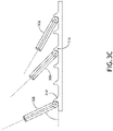
FIG. 3C illustrates a partial elevation view of an enclosed patient suite with mounted medical systems, in accordance with one or more embodiments of the disclosure; -
FIG. 3D illustrates an elevation view of an enclosed patient suite with mounted medical systems, in accordance with one or more embodiments of the disclosure; -
FIG. 3E illustrates an elevation view of an enclosed patient suite with mounted medical systems, in accordance with one or more embodiments of the disclosure; -
FIG. 3F illustrates an elevation view of an enclosed patient suite with mounted medical systems, in accordance with one or more embodiments of the disclosure; -
FIG. 3G illustrates an elevation view of an enclosed patient suite with mounted medical systems, in accordance with one or more embodiments of the disclosure; -
FIG. 4A illustrates an elevation view of an enclosed patient suite with mounted medical systems, in accordance with one or more embodiments of the disclosure; -
FIG. 4B illustrates an elevation view of an enclosed patient suite with mounted medical systems, in accordance with one or more embodiments of the disclosure; -
FIG. 5A illustrates an enclosed patient suite, an aircraft, and a vehicle, in accordance with one or more embodiments of the disclosure; -
FIG. 5B illustrates an enclosed patient suite, a vehicle, and a building, in accordance with one or more embodiments of the disclosure; -
FIG. 6 illustrates an enclosed patient suite and an aircraft, in accordance with one or more embodiments of the disclosure; -
FIG. 7A illustrates an enclosed patient suite and a vehicle, in accordance with one or more embodiments of the disclosure; -
FIG. 7B illustrates an enclosed patient suite and a vehicle, in accordance with one or more embodiments of the disclosure; -
FIG. 7C illustrates an enclosed patient suite and a vehicle, in accordance with one or more embodiments of the disclosure; -
FIG. 7D illustrates an enclosed patient suite and a vehicle, in accordance with one or more embodiments of the disclosure; -
FIG. 7E illustrates an enclosed patient suite and a vehicle, in accordance with one or more embodiments of the disclosure; -
FIG. 8 illustrates portions of an enclosed patient suite and a vehicle, in accordance with one or more embodiments of the disclosure; -
FIG. 9 illustrates a simplified schematic of an enclosed patient suite, in accordance with one or more embodiments of the disclosure; and -
FIG. 10 illustrates a simplified block diagram of an enclosed patient suite with a canopy, in accordance with one or more embodiments of the disclosure. - Reference will now be made in detail to the subject matter disclosed, which is illustrated in the accompanying drawings.
- Before explaining one or more embodiments of the disclosure in detail, it is to be understood the embodiments are not limited in their application to the details of construction and the arrangement of the components or steps or methodologies set forth in the following description or illustrated in the drawings. In the following detailed description of embodiments, numerous specific details may be set forth in order to provide a more thorough understanding of the disclosure. However, it will be apparent to one of ordinary skill in the art having the benefit of the instant disclosure the embodiments disclosed herein may be practiced without some of these specific details. In other instances, well-known features may not be described in detail to avoid unnecessarily complicating the instant disclosure.
- As used herein a letter following a reference numeral is intended to reference an embodiment of the feature or element that may be similar, but not necessarily identical, to a previously described element or feature bearing the same reference numeral (e.g., 1, 1a, 1b). Such shorthand notations are used for purposes of convenience only and should not be construed to limit the disclosure in any way unless expressly stated to the contrary.
- Further, unless expressly stated to the contrary, "or" refers to an inclusive or and not to an exclusive or. For example, a condition A or B is satisfied by any one of the following: A is true (or present) and B is false (or not present), A is false (or not present) and B is true (or present), and both A and B are true (or present).
- In addition, use of "a" or "an" may be employed to describe elements and components of embodiments disclosed herein. This is done merely for convenience and "a" and "an" are intended to include "one," "one or more," or "at least one," and the singular also includes the plural unless it is obvious that it is meant otherwise.
- Finally, as used herein any reference to "one embodiment" or "some embodiments" means that a particular element, feature, structure, or characteristic described in connection with the embodiment is included in at least one embodiment disclosed herein. The appearances of the phrase "in some embodiments" in various places in the specification are not necessarily all referring to the same embodiment, and embodiments may include one or more of the features expressly described or inherently present herein, or any combination of or sub-combination of two or more such features, along with any other features which may not necessarily be expressly described or inherently present in the instant disclosure.
-
FIGS. 1A-10 in general illustrate an enclosed patient suite with mounted medical systems, in accordance with one or more embodiments of the disclosure. - Current medical gurneys are limited in features, providing only minimal support for a patient during transfer between medical locations. For example, a patient may need to be transferred between field locations (e.g., areas of conflict, bases, or the like) and hospitals. The patient may need to be transferred from the field location via an aircraft. The patient may need to be transferred to and/or from the aircraft via a vehicle (e.g., a truck, an ambulance, or the like).
- During the changing of locations, the patient may need to be connected to and/or disconnected from patient monitoring systems at the medical location. For example, the aircraft, the vehicle, and/or the hospital may include medical tools and/or medical devices for stabilizing, analyzing, treating, and/or monitoring the patient during transportation on the medical gurney. The aircraft, the vehicle, and/or the hospital may include connections for couplers (e.g., physical couplers, electrical couplers, fluidic couplers, communicative couplers, or the like) configured to attach to the medical tools and/or medical devices for stabilizing, analyzing, treating, and/or monitoring the patient which may accompany the medical gurney.
- The medical gurneys may be non-standardized with respect to the various types of medical locations and may be difficult to relocate during transfer between medical locations and/or difficult to secure at the medical locations between transfers. For example, where the medical gurney is transferred from the field location via an aircraft, the medical gurney may need to be insertable and/or removable from the aircraft, and may need to be secured within the aircraft during flight. By way of another example, where the medical gurney is transferred via a vehicle, the medical gurney may need to be insertable and/or removable from the vehicle, and may need to be secured within the vehicle during travel. By way of another example, the medical gurney may need to be moveable between the vehicle and the aircraft.
- As such, it would be beneficial to provide an enclosed patient suite with mounted medical systems. The enclosed patient suite may be insertable, removable, moveable, and/or transportable in an aircraft, a vehicle, and/or a building. The enclosed patient suite may include a patient bed. The enclosed patient suite may include mounted medical tools and/or medical devices for stabilizing, analyzing, treating, and/or monitoring the patient, which accompany the patient bed within the enclosed patient suite. The enclosed patient suite may include connections for couplers (e.g., physical couplers, electrical couplers, fluidic couplers, communicative couplers, or the like) configured to attach to the aircraft, the vehicle, and/or the building with the medical tools and/or medical devices for stabilizing, analyzing, treating, and/or monitoring the patient accompanying the patient bed within the enclosed patient suite. The patient bed may be enclosed for privacy and/or for safety (e.g., safety in instances where exposure to an outside environment may threaten the patient and/or medical personnel treating the patient).
- It is noted herein the enclosed patient suite and/or mounted medical systems of the enclosed patient suite may be configured in accordance with aviation guidelines and/or standards put forth by, but not limited to, the Federal Aviation Administration (FAA), the European Aviation Safety Agency (EASA) or any other flight certification agency or organization; the American National Standards Institute (ANSI), Aeronautical Radio, Incorporated (ARINC), or any other standards setting organization or company; the Radio Technical Commission for Aeronautics (RTCA) or any other guidelines agency or organization; or the like. For instance, both the enclosed patient suite and/or mounted medical systems of the enclosed patient suite may be tested per aviation guidelines and/or standards in the most recent versions of the codes set forth in at least 14 C.F.R. Part 25, AIRWORTHINESS STANDARDS: TRANSPORT CATEGORY AIRPLANES in effect at the time of filing.
-
FIGS. 1A and1B in general illustrate anaircraft 100, in accordance with one or more embodiments of the disclosure. Theaircraft 100 may include acargo hold 102a orcabin 102b. Thecargo hold 102a or thecabin 102b may include anenclosed patient suite 104. It is noted herein "enclosed patient suite" and variants of the term including, but not limited to, "patient suite," "enclosed medical suite," "medical suite," "suite," or the like may be considered equivalent, for purposes of the disclosure. - The
suite 104 may include one ormore suite walls 106 coupled to a suite floor, and one ormore doors 108. It is noted herein the coupling or at least partially installing (e.g., insetting, embedding, or the like) medical tools and/or medical devices in the one ormore walls 106 may be considered mounting the medical tools and/or medical devices within thesuite 104, for purposes of the disclosure. - Where the
suite 104 is rectangular, the one ormore suite walls 106 may form at least three sides of thesuite 104. For example, the one ormore suite walls 106 may include threesuite walls 106 which form three sides of thesuite 104 and one ormore doors 108 which form a fourth side of thesuite 104. By way of another example, the one ormore suite walls 106 may include foursuite walls 106, where threesuite walls 106 form three sides of thesuite 104 and afourth suite wall 106 partially forms a fourth side of thesuite 104, with one ormore doors 108 forming the remainder of the fourth side. In it noted herein "walls," "panels," "partitions," "shells," and "screens" may be configured equivalent, for purposes of the disclosure. - The one or
more doors 108 may be configured to allow access into thesuite 104. For example, adoor 108 may rest on a corresponding track (or set of tracks), and may actuate along the track (e.g., in a sliding motion) between a closed position and an open position. For instance, thedoor 108 may slide within a cavity (e.g.,cavity 206, as illustrated in at leastFIG. 2 ) defined within a suite wall 106 (e.g., is a pocket door), against an exterior surface of asuite wall 106, or an interior surface of asuite wall 106. By way of another example, adoor 108 may be coupled to asuite wall 106 via one or more hinge assemblies. By way of another example, adoor 108 may be coupled to asuite wall 106 via one or more interlocking assemblies (e.g., tab and groove assemblies, latch assemblies, snap-fit or interference assemblies, or the like), where the one or more interlocking assemblies may be disassembled to allow for access into thesuite 104. By way of another example, adoor 108 may be configured to draw, roll up, or otherwise collapse when actuating from a closed position to an open position, and vice versa when actuating from the open position to the closed position. - It is noted herein the
suite 104 may not include the one ormore doors 108, and that the one ormore suite walls 106 may instead leave a gap or opening to allow for access into thesuite 104. - The
suite 104 may include a set ofwheels 110. For example, the set ofwheels 110 may include one or more caster wheels and/or one or more fixed wheels. By way of another example, the set ofwheels 110 may include, but are not limited to, solid plastic wheels, hard foam wheels, solid rubber wheels, solid tubeless pneumatic wheels, tubed pneumatic wheels, or the like. - The
suite 104 may include one ormore floor couplers 112 configured to couple to a floor-mountedcomponent 114 within afloor 116 of thecargo hold 102a and/or thecabin 102b of theaircraft 100. For example, the one ormore floor couplers 112 may include, but are not limited to, arail brake 112. By way of another example, the one or more floor-mountedcomponents 114 may include, but are not limited to, arail 114. It is noted herein the one or more floor-mountedcomponents 114 may include tracks, brackets, or other floor-mountedcomponents 114. - The one or
more floor couplers 112 may include one ormore brake pads 118 configured to engage a surface of the floor-mountedcomponent 114, where the one ormore brake pads 118 are manually engaged or disengaged, and/or are engaged or disengaged with one or more mechanical, electromechanical, pneumatic, or hydraulic actuation devices (e.g., assemblies, controls, actuators such as motors, or the like). By way of another example, the one ormore floor couplers 112 may include feet configured to be inserted within a hole in the floor-mountedcomponent 114. - The one or
more floor couplers 112 may be positioned between wheels of the set ofwheels 110 or outside of wheels of the set ofwheels 110. - The
suite 104 may include apatient bed 120. It is noted herein "patient bed" and variants of the term including, but not limited to, "bed," or the like may be considered equivalent, for purposes of the disclosure. -
FIGS. 2-4B in general illustrate example embodiments of thesuite 104, in accordance with one or more embodiments of the disclosure. Thesuite 104 may include a number of medical tools and/or medical devices for stabilizing, analyzing, treating, and/or monitoring the patient. It is noted herein the medical tools and/or medical devices as described with respect to at leastFIGS. 2-4B may be considered medical systems of thesuite 104. Thesuite 104 may include a number of auxiliary components for securing the medical tools and/or medical devices, medical supplies, personal effects of the patient and/or the medical personnel. For example, the auxiliary components may include, but are not limited to, storage compartments, trays, shelves, tool racks, or the like. - Referring now to
FIG. 2 , a top plan view of an example embodiment of thesuite 104 is illustrated, in accordance with one or more embodiments of the disclosure. - The
suite 104 may include apatient area 200. For example, thepatient area 200 may include an area in which thepatient bed 120 is located proximate to the one ormore doors 108. Thepatient area 200 may be accessed via anopening 202 within the one ormore suite walls 106, where theopening 202 is created by the one ormore doors 108 actuating into an open position (e.g., within the cavity 206). It is noted herein theopening 202 may lead directly into thepatient area 200, or may lead to a pass-througharea 204 before entering thepatient area 202. For example, the pass-througharea 204 may be empty space between the surrounding environment and thepatient area 200. By way of another example, the pass-througharea 204 may be of a length, width, and/or depth necessary to accommodate space needed for medical tools, medical devices, and/or auxiliary components either coupled to or at least partially installed in (e.g., inset, embedded, or the like) the one ormore suite walls 106 or underneath thepatient bed 120. - The
suite 104 may include one or more storage compartments 208. The one ormore storage compartments 208 may be either coupled to or at least partially installed in (e.g., inset, embedded, or the like) the one ormore suite walls 106 or underneath thepatient bed 120. - The one or
more storage compartment 208 may be configured to receive and hold medical supplies, medical devices, medical tools, or the like. The one ormore storage compartments 208 may include one or more safety devices (e.g., air masks, personal floatation devices, or the like). - The one or
more storage compartments 208 may include a storage compartment (e.g., a wardrobe) configured to receive long and/or large items (e.g., passenger amenities needing to be hung, carry-on luggage, or the like) that require an increased space and/or that a passenger may prefer to store in a substantially vertical or upright orientation. - The one or
more storage compartments 208 may be configured to receive and hold (e.g., contain, secure, or the like) one or more passenger amenities including, but not limited to, paper-printed materials (e.g., magazines, newspapers, pamphlets, or the like), select personal electronic devices (e.g., phones, tablets, phablets, laptops, music devices, digital video disc (DVD) players, handheld gaming consoles or devices, or the like), food products, drink products, or the like. - The one or
more storage compartments 208 may include one or more electronic connections for one or more passenger amenities such as, but not limited to, one or more charging ports, one or more charging cables, or the like. - The one or
more storage compartments 208 may include one or more electronic connections in communication with one or more components of thesuite 104 such as, but not limited to, one or more display device connection ports, one or more display device connection cables, one or more audio output jacks (e.g., headphone jacks), one or more audio input jacks, or the like. - The one or
more storage compartments 208 may include one ormore doors 210. For example, adoor 210 may rest on a corresponding track (or set of tracks), and may actuate along the track (e.g., in a sliding motion) between a closed position and an open position. For instance, thedoor 210 may slide within acavity 212 defined within the suite wall 106 (e.g., is a pocket door), against an exterior surface of asuite wall 106, or an interior surface of asuite wall 106. By way of another example, adoor 210 may be coupled to asuite wall 106 via one or more hinge assemblies. By way of another example, adoor 210 may be coupled to asuite wall 106 via one or more interlocking assemblies (e.g., tab and groove assemblies, latch assemblies, snap-fit or interference assemblies, or the like), where the one or more interlocking assemblies may be disassembled to allow for access into acorresponding storage compartment 208. By way of another example, adoor 210 may be configured to draw, roll up, or otherwise collapse when actuating from a closed position to an open position, and vice versa when actuating from the open position to the closed position. The one ormore storage compartments 208 may be accessible from within the suite 104 (e.g., where the one ormore doors 210 are directed inward into the patient area 200) or from outside the suite 104 (e.g., where the one ormore doors 210 are directed outward into thecargo hold 102a and/or thecabin 102b). - The
suite 104 may include one or more refrigerators orrefrigeration units 214. For example, the one ormore refrigeration units 214 may be configured to store medical supplies (e.g., medicine) needing to be kept in a particular (e.g., cold) environment. The one ormore refrigeration units 214 may include one or more components (e.g., doors, lids, or the like) configured to allow access into the one ormore refrigeration units 214. The one ormore refrigeration units 214 may be accessible from within the suite 104 (e.g., where the one or more components configured to allow access are directed inward into the patient area 200) or from outside the suite 104 (e.g., where the one or more components configured to allow access are directed outward into thecargo hold 102a and/or thecabin 102b). - The
suite 104 may include one ormore sterilizers 216. For example, the one ormore sterilizers 216 may be configured to store medical supplies (e.g., medicine), medical tools, and/or medical devices needing to be kept in a sterilized environment. By way of another example, the one ormore sterilizers 216 may be configured to sterilize the medical tools and/or medical devices placed within the one ormore sterilizers 216. For instance, the one ormore sterilizers 216 may include, but are not limited to, an autoclave, a glass bead sterilizer, or the like. The one ormore sterilizers 216 may include one or more components (e.g., doors, lids, or the like) configured to allow access into the one ormore sterilizers 216. The one ormore sterilizers 216 may be accessible from within the suite 104 (e.g., where the one or more components configured to allow access are directed inward into the patient area 200) or from outside the suite 104 (e.g., where the one or more components configured to allow access are directed outward into thecargo hold 102a and/or thecabin 102b). - The
suite 104 may include one or morepatient monitoring systems 218. For example, the one or morepatient monitoring systems 218 may include a controller, with components as described throughout the disclosure. By way of another example, the one or morepatient monitoring systems 218 may include a user interface, with components as described throughout the disclosure. - The
suite 104 may include abattery 220. For example, thebattery 220 may be configured to maintain power for medical tools and/or medical devices installed within thesuite 104 during transfer between locations (e.g., the field, a vehicle, an aircraft, a hospital, or the like), during power outages, or during general operation. Thesuite 104 may include an uninterruptible power supply (UPS) 222. For example, theUPS 222 may be configured to provide backup to thebattery 220. By way of another example, theUPS 222 may be configured to charge thebattery 220. TheUPS 222 may be couplable to theaircraft 100. In this regard, thesuite 104 may not need to be coupled to a surrounding power system (e.g., within theaircraft 100, within a vehicle, within a hospital, or the like), allowing for complete mobility of thesuite 104. It is noted herein, however, thesuite 104 may include connections for couplers (e.g., physical couplers, electrical couplers, fluidic couplers, communicative couplers, or the like) configured to attach to a surrounding power system for purposes of obtaining power and/or data. - Referring now to
FIGS. 3A-3G , elevation views of example embodiments of thesuite 104 are illustrated, in accordance with one or more embodiments of the disclosure. - The
suite 104 may include one or more identification (ID) tags 300. For example, the one or more identification (ID) tags 300 may include, but are not limited to, radio frequency identification tags (RFID tags). By way of another example, the one ormore ID tags 300 may include Quick Response (QR) codes, handwritten or printed tags, or the like. It is noted herein the one ormore ID tags 300 may be tangible objects or may be graphically displayed on a user interface. The one ormore ID tags 300 may be coupled to an exterior surface (e.g., within an environment of thecargo hold 102a and/orcabin 102b) or an interior surface of the one ormore suite walls 106. - It is noted herein the
door 108 is illustrated in an open position inFIG. 3A , and in a closed position inFIG. 3B . - As illustrated in at least
FIG. 3A , thedoor 108 may include adoor actuator 302. For example, thedoor actuator 302 may include, but is not limited to, a hole, a handle, a latch, or other device configured to be acted upon by a user to actuate thedoor 108. For instance, depending on the type and/or position of the handle or latch 302 on thedoor 108, thedoor 108 may fully nest within thecavity 206 in the one ormore suite walls 106, or may protrude a select amount from within thecavity 206. It is noted herein thedoor actuator 302 may include one or more mechanical, electromechanical, pneumatic, or hydraulic actuation devices (e.g., assemblies, controls, actuators such as motors, or the like). In general, it is noted herein any door on theenclosed patient suite 104 may include adoor actuator 302 as described above. Therefore, the above description should not be interpreted as a limitation on the scope of the disclosure but merely an illustration. - The
suite 104 may include one ormore surfaces 304 at the top of the one ormore suite walls 106. For example, the one ormore surfaces 304 may be used as temporary surfaces (or long-term, depending on whether securing components restraints are installed on the one or more surfaces 304) for access while attending a patient in thepatient bed 120. - It is noted herein the
door 210 is illustrated in a closed position inFIG. 3A , and in an open position inFIG. 3B . As illustrated in at leastFIG. 3B , the one ormore storage compartments 208 may include one ormore shelves 306 fixed in a defined cavity within the one or more storage compartments 208. For example, the one or more shelves may be accessible when thedoor 210 is not in the closed position. - The
patient bed 120 may be rotatable about an axis cross-wise through thepatient bed 120 into a position including, but not limited to, an upright or raised position, one or more lounge or reclined positions, and a lie-flat or bed position. For example, thepatient bed 120 may transition directly between the upright position and the lie-flat or bed position. By way of another example, it is noted herein thepatient bed 120 may transition through one or more reclined positions between the upright position and the lie-flat or bed position. By way of another example, thepatient bed 120 may transition into one or more reclined positions in a motion separate from the transition between the upright position and the lie-flat or bed position. Therefore, the above description should not be interpreted as a limitation on the scope of the disclosure but merely an illustration. - It is noted herein the
patient bed 120 is illustrated in a lie-flat or bed position inFIG. 3A , and in a raised position inFIG. 3B . Thepatient bed 120 may be positioned in the lie-flat or bed position and in a raised position at a particular time by anarm 308. For example, thearm 308 may support anupper portion 310 of thepatient bed 120 at anangle 312. For example, the angle may range from 0° to 60°. For instance, as illustrated inFIG. 3C , the angle may be selected by engaging anotch 314 of a set ofnotches 314 with thearm 308, where the set ofnotches 314 is in afloor portion 316 of thepatient area 200. It is noted herein the positioning of theupper portion 310 may be selected via a mechanical, electromechanical, pneumatic, or hydraulic actuation device (e.g., assemblies, controls, actuators such as motors, or the like). For example, the mechanical, electromechanical, pneumatic, or hydraulic actuation device may include, but is not limited to, a rack-and-pinion assembly (e.g., manually driven or driven with an electric motor and a controller or switch), where thearm 308 is coupled to the rack-and-pinion assembly, in place of the set ofnotches 314. - As illustrated in at least
FIGS. 3D-3G , thesuite 104 may include one ormore support members 318. The one ormore support members 318 may include one or more legs or primary members, to which at least some of the one ormore wheels 110 may couple. For example, thesuite 104 may include 4, 6, 8, 10, 12 or other number ofsupport members 318, and a corresponding number ofwheels 110. - The one or more primary members may be configured to fold under the
suite 104 when not in use. For example, the one ormore wheels 110 may be configured to fold underneath thesuite 104, with the folding of the one or more primary members. The one or moreprimary members 318 may be telescopic, and may be configured to collapse when not in use. For example, the one ormore wheels 110 may be configured to collapse underneath thesuite 104, with the collapsing of the one or moreprimary members 318. It is noted herein the one ormore support members 318 may include auxiliary cross-members configured to provide support to the one or more primary members. - In general, the one or
more support members 318 may actuate (e.g., fold or collapse) between a raised position and a lowered position. For example, a distance between the raised position and the lowered position may range from 0 inches to 24 inches (0-61 cm). The actuation may be caused by one or more mechanical, electromechanical, pneumatic, or hydraulic actuation devices (e.g., assemblies, controls, actuators such as motors, or the like). - It is noted herein the
suite 104 may include indicators (e.g., visual, auditory, graphical, or the like) to indicate when the one ormore support members 318 are actuating and/or when the one ormore floor couplers 112 are engaged or disengaged from thefloor 116. For example, the one or more indicators may include, but are not limited to, one or more lights either coupled to or at least partially installed (e.g., inset, embedded, or the like) within the one ormore suite walls 106, a housing of the one ormore floor couplers 112, or elsewhere on thesuite 104. - The
suite 104 may include one ormore shelves 320 underneath the one ormore suite walls 106. The one ormore shelves 320 may be coupled to the one ormore support members 318. The one ormore shelves 320 may be configured to receive and contain (e.g., house, be coupled to, or the like) one or more cables, medical supplies, medical tools, and/or medical devices. For example, one or more of the medical tools and/or medical devices for stabilizing, analyzing, treating, and/or monitoring the patient may be either coupled to or at least partially installed in (e.g., inset, embedded, or the like) a space underneath the one or more suite walls 106 (e.g., on the one ormore shelves 320, in one or more cavities defined within the one ormore shelves 320, or the like). It is noted herein the coupling or at least partially installing (e.g., insetting, embedding, or the like) medical tools and/or medical devices in the space underneath the one ormore suite walls 106 may be considered mounting the medical tools and/or medical devices within thesuite 104, for purposes of the disclosure. - The one or
more shelves 320 may be stowable underneath the one ormore suite walls 106 prior to movement of thesuite 104, to secure any cables, medical supplies, medical tools, and/or medical devices on the one ormore shelves 320 against the underside of the one ormore suite walls 106. Thesuite 104 may include one or more couplers orbrackets 322 configured to hold the one or more shelves in a stowed position. - It is noted herein one or
more wheels 110 may be coupled to the underside of the one ormore suite walls 106 directly as a fixed-position wheel 110, as opposed to being coupled via the one ormore support members 318. For example, the fixed-position wheels 110 may be leading oredge wheels 110. In addition, it is noted herein one ormore wheels 110 may be coupled to the underside of the one ormore suite walls 106 via a fixed-length support member 318, as opposed to being coupled via anactuatable support member 318. For example, thewheels 110 on fixed-length support members 318 may becenter wheels 110. - Referring now to
FIGS. 4A and 4B , elevation views of example embodiments of thesuite 104 are illustrated, in accordance with one or more embodiments of the disclosure. For example,FIG. 4A illustrates a right elevation view of an interior surface of afirst suite wall 106, andFIG. 4B illustrates a right elevation view of an exterior surface of asecond suite wall 106 opposite thefirst suite wall 106. - As illustrated in
FIG. 4A , alocking tool rack 400 may be either coupled to or at least partially installed in (e.g., inset, embedded, or the like) thesuite wall 106. For example, thelocking tool rack 400 may include, but is not limited to, a posi-locking instrument holder, a twist-lock tool holder, a set of mounting bars, a set of magnetic strips, or the like. - It is noted herein the size of the one or
more sterilizers 216 may be dependent on the size of the one ormore refrigeration units 214, as illustrated inFIG. 4A . - As illustrated in
FIG. 4B , thesuite wall 106 may include one or more mount locations 402. For example, the one or more mount locations 402 may include, but are not limited to, one or more holes through thesuite wall 106 or hooks either coupled to or at least partially installed in (e.g., inset, embedded, or the like) thesuite wall 106. For instance, the one or more holes or hooks may be configured to hold medical supplies (e.g., an intravenous solution (IV) bag, a blood transfer pouch, or the like), a coat or other receive long and/or large item needing to be hung, or the like. - The
suite 104 may include one or more high-touch areas, or frequent touchpoints in contact with different users, which may have a high potential to transfer microbes (e.g., viruses, pathogens, microorganisms) between the users. In one non-limiting example, the high-touch areas may include portions of thesuite walls 106 such as, but not limited to, the interior or exterior surfaces of thesuite walls 106, or lead edges of thesuite walls 106 proximate to theopening 202 of thesuite 104 providing access to thepatient area 200 from thecargo hold 102a and/or thecabin 102b. In another non-limiting example, the high-touch areas may include the various components installed within thesuite 104 as listed throughout the disclosure. - In general, the one or more high-touch areas may be fabricated from an easy-to-clean material and/or may be protected with coatings. For example, the one or more high-touch areas may be protected with coatings (e.g., antimicrobial, antiviral, antibacterial, or the like) configured to prevent the transfer of microbes. It is noted herein the coatings may be in addition to or instead of disinfection of the high-touch areas during regular cleanings, fogging, and/or cleaning of the
suite 104. - It is noted herein the
suite 104 may include one or more stowable seats (e.g., flight attendant seats or other stowable seats) coupled to thesuite 104. - In general, the stowable seat may be translatable (e.g., trackable or slidable). The stowable seat may be rotatable about an axis cross-wise through the stowable seat into a position including, but not limited to, an upright or raised position, one or more lounge or reclined positions, and a lie-flat or bed position. For example, the stowable seat may transition directly between the upright position and the lie-flat or bed position. By way of another example, it is noted herein the stowable seat may transition through one or more reclined positions between the upright position and the lie-flat or bed position. By way of another example, the stowable seat may transition into one or more reclined positions in a motion separate from the transition between the upright position and the lie-flat or bed position. Therefore, the above description should not be interpreted as a limitation on the scope of the disclosure but merely an illustration.
- The stowable seat may be rotatable about an axis (e.g., swivelable). The stowable seat may be fully positionable between the outer limits of motion as defined by one or more components of the
suite 104. It is noted herein an upright or raised position may be considered a taxi, takeoff, or landing (TTOL) position during select stages of flight (though the upright or raised position is not limited to use during the select stages of flight as the TTOL position, but also may be used at any point during the flight), for purposes of the present disclosure. In addition, it is noted herein that any position that does not meet the above-defined requirements of the TTOL position may be considered a non-TTOL position, for purposes of the present disclosure. Further, it is noted herein the stowable seat may be actuatable (e.g., translatable and/or rotatable) from the TTOL position to a non-TTOL position, and/or vice versa. Further, it is noted herein the stowable seat may be capable of a fully upright or raised position, and that the TTOL position may have a more reclined seat back cushion and a more angled upward seat pan cushion as compared to the fully upright or raised position. Therefore, the above description should not be interpreted as a limitation on the present disclosure but merely an illustration. - The stowable seat may be configured to avoid contact with the one or more components of the
suite 104 when transitioning between positions (e.g., between the upright or raised position and the lie-flat or bed position). - It is noted herein the embodiments of the disclosure related to the placement of medical supplies, medical tools, and/or medical devices within the
enclosed patient suite 104 are provided only as example embodiments, and that the medical supplies, medical tools, and/or medical devices may be located anywhere within theenclosed patient suite 104 as allowed by the dimensions of the medical supplies, medical tools, and/or medical devices. Therefore, the above description should not be interpreted as a limitation on the scope of the disclosure but merely an illustration. - In this regard, the
enclosed patient suite 104 and the included medical tools, medical devices, and other components installed within theenclosed patient suite 104 may be moveable as a single, self-contained unit between environments. Being a single, self-contained unit may allow for all necessary medical systems for stabilizing, analyzing, treating, and/or monitoring a patient being transported in theenclosed patient suite 104. Although the capability may be included within theenclosed patient suite 104, theenclosed patient suite 104 may be able to operate without connecting to any surrounding systems and/or may be able to move without disconnecting any patient-supporting systems. -
FIGS. 5A-8 in general illustrate movement of theenclosed patient suite 104 through environments, in accordance with one or more embodiments throughout the disclosure. - The
suite 104 is not limited to the aviation environment (e.g., the aircraft 100) and/or the aircraft components within the aviation environment (e.g., thecargo hold 102a, thecabin 102b, or the like). For example, thesuite 104 may be configured for any type of vehicle known in the art. For example, the vehicle may be any air, space, land, or water-based personal equipment or vehicle; any air, space, land, or water-based commercial equipment or vehicle; any air, space, land, or water-based military equipment or vehicle known in the art. For instance, the vehicle may include a truck or an ambulance. By way of another example, thesuite 104 may be configured for commercial or industrial use in either a home or a business (e.g., within a hospital). - Referring now to
FIG. 5A , thesuite 104 may be transferred from theaircraft 100. At atime 500, thesuite 104 may be in theaircraft 100. It is noted herein thesuite 104 may be coupled to theaircraft 100 for at least one of power transfer or data transfer at thetime 500. At atime 510, thesuite 104 may be unloaded down aramp 502 of theaircraft 100. At atime 520, thesuite 104 may be transported to a vehicle 522 (e.g., an ambulance, a truck, or the like). At atime 530, thesuite 104 may be loaded into thevehicle 522. For example, avehicle 522 may include afloor 532 upon which thesuite 104 may be loaded. It is noted herein thesuite 104 may be coupled to thevehicle 522 for at least one of power transfer or data transfer at thetime 530. - Referring now to
FIG. 5B , thesuite 104 may be transferred from thevehicle 522. At atime 540, thesuite 104 may be in thevehicle 522. It is noted herein thesuite 104 may be coupled to thevehicle 522 for at least one of power transfer or data transfer at thetime 540. At atime 550, thesuite 104 may be unloaded from thevehicle 522. At atime 560, thesuite 104 may be transported to a building 562 (e.g., a hospital, or the like). At atime 570, thesuite 104 may be positioned at a designated location within thebuilding 562. It is noted herein thesuite 104 may be coupled to thebuilding 562 for at least one of power transfer or data transfer at thetime 570. - Referring now to
FIG. 6 , details of the motion of thesuite 104 betweentimes time 500, thesuite 104 may be coupled to a floor-mountedcomponent 114 in thefloor 116 of theaircraft 100 with the one or more couplers 112 (e.g., rail brake, feet, or the like) At thetime 510, thesuite 104 may be uncoupled from the floor-mountedcomponent 114 and be transported down theramp 502. For example, the one ormore couplers 112 may slide off the rail after thesuite 104 is uncoupled while being moved to exit theaircraft 100. Although only onesuite 104 is illustrated as being coupled to the floor-mountedcomponent 114 at thetime 500, it is noted hereinmultiple suites 104 may be installed on a single floor-mountedcomponent 114. - Referring now to
FIG. 7A-7E , details of the motion of thesuite 104 betweentimes time 700, an outsidefixed position wheel 110 may come into contact with thefloor 532 of thevehicle 522, and anadjacent support member 318 withwheel 110 may be actuated to raise thewheel 110 from a ground height to afloor 532 height. At atime 710, the raisedwheel 110 coupled to theactuatable support member 318 may come into contact with thefloor 532 of thevehicle 522, allowing thesuite 104 to further move into thevehicle 522. At atime 720, a fixed-length support member 318 withwheel 110 may come into contact with thefloor 532 of thevehicle 522 and thesuite 104 may further move into thevehicle 522, effectively shifting the bulk of the weight onto thefloor 532 of the vehicle 522 (as opposed to the ground outside the vehicle 522), and a second support member 422 withwheel 110 may be actuated to raise thewheel 110 from the ground height to thefloor 532 height. - It is noted herein the fixed
position wheel 110 and/or the fixed-length support member 318 withwheel 110 may be replaced with anactuatable support member 318 withwheel 110. - Referring now to
FIG. 8 , thesuite 104 may include a coupling assembly configured to hold thesuite 104 in thevehicle 522. For example, the coupling assembly may include an attach point 800 (e.g., hook or eye ring, component of an interlocking assembly, or the like) on the suite 104 (e.g., on the housing of a coupler 112) and an attach point 802 (e.g., hook or eye ring, component of an interlocking assembly, or the like) in thefloor 532 of thevehicle 522, where the attachpoint 800 and the attachpoint 802 may be coupled. For example, a rope orstrap 804 may pass through the attachpoint 800 and the attachpoint 802. By way of another example, a bar orlinkage 804 may couple to the attachpoint 800 and the attachpoint 802. - It is noted herein the steps illustrated in
FIGS. 5A-8 may be reversed (or at least performed in a different order) to remove thesuite 104 from thebuilding 562, to remove thesuite 104 from thevehicle 522, and/or load thesuite 104 onto theaircraft 100. In addition, it is noted herein the movement of thesuite 104 between theaircraft 100 and thevehicle 522 and/or the movement of thesuite 104 between thevehicle 522 and thebuilding 562 may include more or fewer steps. Therefore, the above description should not be interpreted as a limitation on the scope of the disclosure but merely an illustration. - Although not shown, it should be understood the
suite 104 may move directly between theaircraft 100 and thebuilding 562. Therefore, the above description should not be interpreted as a limitation on the scope of the disclosure but merely an illustration. - It is noted herein the one or
more support members 318 being in the raised position may actuate the correspondingwheels 110 closer to the underside of the one ormore suite walls 106, decreasing a distance between an underside of the one ormore suite walls 106 and a floor of the aircraft 100 (e.g., the floor 116), the vehicle 522 (e.g., the floor 532), or thebuilding 562. In addition, it is noted herein the one ormore support members 318 being in the lowered position may actuate the correspondingwheels 110 farther from the underside of the one ormore suite walls 106, increasing a distance between an underside of the one ormore suite walls 106 and a floor of an aircraft, vehicle, or building. - It is noted herein the embodiments of the disclosure related to the dimensions of the
enclosed patient suite 104 and/or of components installed within theenclosed patient suite 104 are provided only as example embodiments. In general, the enclosed gurney suite may be dimensioned based on a standardized layout for insertion, removal, and transport within any of a number of aircraft cargo holds 102a oraircraft cabins 102b of theaircraft 100, thevehicle 522, and/or thebuilding 562. For example, thesuite 104 may be dimensioned to fit within standard building doors, standard ambulance doors, standard aircraft doors or loading ramps, or the like. Therefore, the above description should not be interpreted as a limitation on the scope of the disclosure but merely an illustration. -
FIG. 9 illustrates a simplified schematic or block diagram of theenclosed patient suite 104, in accordance with one or more embodiments of the disclosure. It is noted herein the solid connection lines may represent power transfer and the broken connection lines may represent data transfer inFIG. 9 . - The
UPS 222 may be coupled to thebattery 220. TheUPS 222 may be coupled to one or more of theaircraft 100, avehicle 522, or abuilding 562 via connections for couplers (e.g., physical couplers, electrical couplers, fluidic couplers, communicative couplers, or the like) configured to attach to a surrounding power system for purposes of obtaining power and/or data. For example, the coupler may include a 120V wall plug. - The
suite 104 may include apower switching system 900. Thepower switching system 900 may determine which power source powers the medical systems in thesuite 104 at a given time. For instance, thepower switching system 900 may allow the external surrounding power system to charge thebattery 220 and/or theUPS 222 when thesuite 104 is coupled to theaircraft 100, thevehicle 522 or thebuilding 562. In addition, thepower switching system 900 may allow the external surrounding power system to power medical systems of thesuite 104 when thesuite 104 is coupled to theaircraft 100, thevehicle 522 or thebuilding 562. Further, thepower switching system 900 may switch thebattery 220 to power medical systems of thesuite 104 when thesuite 104 is uncoupled from theaircraft 100, thevehicle 522 or thebuilding 562. Further, thepower switching system 900 may switch theUPS 222 to power medical systems of thesuite 104 when thebattery 220 fails or is depleted. - The
battery 220, thepower switching system 900, and the external surrounding power system may each be coupled to the one ormore refrigeration units 214, the one ormore sterilizers 216, thepatient monitoring system 218, anoxygen system 902,lighting 904 within thesuite 104, and/or acontroller 906, depending on thepower switching system 900. For example, thelighting 904 may be either coupled to or at least partially installed in (e.g., inset, embedded, or the like) the one ormore suite walls 106. - The
controller 906 may be coupled to anetwork 908, one or morehydraulic systems 910 including the one or more support members 318 (e.g., along with the power switching system 900), and/or the ID tags 300. - The
controller 906 may include one ormore processors 912. Thecontroller 906 may includememory 914, and the one ormore processors 912 may be configured to execute a set ofprogram instructions 916 stored inmemory 914, the set ofprogram instructions 916 being configured to cause the one ormore processors 912 to carry out various steps and processes of the present disclosure. - The
controller 906 may include one ormore communication interfaces 918 configured to couple to at least thenetwork 908. For example, thenetwork 908 may include components configured to connect via a wireline (e.g., copper wire, fiber optic cable, and the like) or wireless connection (e.g., RF coupling, IR coupling, data network communication (e.g., WiFi, WiMax, 3G, 4G, 4G LTE, 5G, Bluetooth, and the like) for remote medical input including the transmitting and receiving of medical data and/or medical instructions. - The one or
more processors 912 may include any one or more processing elements known in the art. In this sense, the one ormore processors 912 may include any microprocessor-type device configured to execute software algorithms and/or instructions. The one ormore processors 912 may consist of a desktop computer, mainframe computer system, workstation, image computer, parallel processor, or other computer system (e.g., networked computer) configured to execute a program configured to operate thesuite 104, as described throughout the present disclosure. It should be recognized that the steps described throughout the present disclosure may be carried out by a single computer system or, alternatively, multiple computer systems. Furthermore, it should be recognized that the steps described throughout the present disclosure may be carried out on any one or more of the one ormore processors 912. In general, the term "processor" may be broadly defined to encompass any device having one or more processing elements, which execute program instructions frommemory 914. Moreover, different subsystems of the suite 104 (e.g., the patient monitoring system 218) may include processor or logic elements suitable for carrying out at least a portion of the steps described throughout the present disclosure. Therefore, the above description should not be interpreted as a limitation on the present disclosure but merely an illustration. - The
memory 914 may include any storage medium known in the art suitable for storing program instructions executable by the associated one ormore processors 912 and the data received/generated by thesuite 104. For example, thememory 914 may include a non-transitory memory medium. For instance, thememory 914 may include, but is not limited to, a read-only memory (ROM), a random-access memory (RAM), a magnetic or optical memory device (e.g., disk), a magnetic tape, a solid-state drive and the like. It is further noted thatmemory 914 may be housed in a common controller housing with the one ormore processors 912. Thememory 914 may be located remotely with respect to the physical location of theprocessors 912 andcontroller 906. Thememory 914 may maintain program instructions for causing the one ormore processors 912 to carry out the various steps described through the present disclosure. - The
suite 104 may include auser interface 920 communicatively coupled to thecontroller 906. Theuser interface 920 may include, but is not limited to, one or more desktops, tablets, smartphones, smart watches, or the like. Theuser interface 920 may include one or more displays 922 used to display data of thesuite 104 to a user. Theuser interface 920 may include one or more user input devices 924 used to interact with the one or more displays 922 and/or components coupled to theuser interface 920 either directly or indirectly (e.g., via the controller 906). - The one or more displays 922 of the
user interface 920 may include any display known in the art. For example, the display may include, but is not limited to, a liquid crystal display (LCD), an organic light-emitting diode (OLED) based display, or a CRT display. Those skilled in the art should recognize that any display device capable of integration with auser interface 920 is suitable for implementation in the present disclosure. In another embodiment, a user may input selections and/or instructions responsive to data displayed to the user via the one or more user input devices 924 of theuser interface 920. The one or more user input devices 924 may include one or more toggles, switches, knobs, or other user input devices. -
FIG. 10 illustrates a simplified block diagram of theenclosed patient suite 104, in accordance with one or more embodiments of the disclosure. - The
suite 104 may include acanopy 1000. For example, thecanopy 1000 may be fabricated from a rigid material (e.g., metal, plastic, or the like) and configured to retain its shape and/or size. By way of another example, thecanopy 1000 may be fabricated from a non-rigid material (e.g., fabric, mesh, netting, or the like) and configured to be drawable, foldable, collapsible, or the like. - The
canopy 1000 may be integrated with the one ormore suite walls 106, or may be attachable to the one ormore suite walls 106 and/or the one ormore doors 108. For example, thecanopy 1000 may be attachable via interlocking assemblies configured to allow for a quick release of thecanopy 1000 from the one or more suite walls 106 (e.g., tab and groove assemblies, latch assemblies, snap-fit or interference assemblies, or the like), and/or fasteners (e.g., fasteners such as washers, threaded nuts, bushings, spacers, or the like). By way of another example, thecanopy 1000 may be removed and stored in theaircraft 100 when not required to enclose the patient for privacy and/or for safety (e.g., safety in instances where exposure to an outside environment may threaten the patient and/or medical personnel treating the patient). It is noted herein a gap between thecanopy 1000 and the one ormore suite walls 106 may be filled in with a filler component fabricated from a solid soft material (e.g., a foam block or shield, a rubber block or shield, or the like), a solid hard material (e.g., a plastic block or shield, a metal block or shield, or the like), a fluidic hardening material (e.g., caulk or other sealing compound), or the like. - The
suite 104 may include adome canopy 1000, a flat canopy 1000 (e.g., a ceiling), or a pitched canopy 1000 (e.g., acanopy 1000 that comes to a point at its height). It is noted herein, however, thesuite 104 may includeextra-high walls 106, such that thecanopy 1000 does not form part of the sides of thesuite 104. - The
suite 104 may include one ormore mount points 1002 for thecanopy 1000. For example, components of one or more interlocking assemblies (e.g., tab and groove assemblies, latch assemblies, snap-fit or interference assemblies, or the like) may be attached to thesuite 104 at the one ormore mount points 1002, to which corresponding components of the one or more interlocking assemblies attached to thecanopy 1000 may couple. - The
suite 104 may include anupper door 1004. For example, theupper door 1004 may be a portion of thecanopy 1000 coupled to thedoor 108 when thecanopy 1000 is coupled to the one ormore suite walls 106. By way of another example, theupper door 1004 may be integrated with thedoor 108. For instance, theupper door 1004 may be stowable against a surface (e.g., exterior surface or interior surface) of thedoor 108, or may be stowable in a cavity defined within thedoor 108, when thecanopy 1000 is not attached to or integrated with the one ormore suite walls 106. Theupper door 1004 may be configured to actuate independently of thedoor 108 and/or may be configured to actuate with an actuation of thedoor 108. - A
portion 1006 of theupper door 1004 may be open to allow for viewing into thepatient area 200, although thedoor 108 may be in the closed position. For example, theportion 1006 may be a cut-out within theupper door 1004. By way of another example, theportion 1006 may be closeable (e.g., with a door, screen, curtain, or the like) for privacy and/or for safety (e.g., safety in instances where exposure to an outside environment may threaten the patient and/or medical personnel treating the patient). - It is noted herein the
lighting 904, as described throughout the disclosure, may be either coupled to or at least partially installed in (e.g., inset, embedded, or the like) thecanopy 1000. In addition, it is noted herein portions of the canopy 1000 (e.g., exterior or interior surfaces) may include one or more high-touch areas, where the high-touch areas are fabricated from an easy-to-clean material and/or may be protected with coatings, as described throughout the disclosure. - In this regard, the
enclosed patient suite 104 with mounted medical systems may be insertable, removable, moveable, and/or transportable in anaircraft 100, a vehicle 522 (e.g., an ambulance, or the like), and/or a building 562 (e.g., a hospital, or the like). Theenclosed patient suite 104 may include thepatient bed 120. Theenclosed patient suite 104 may include mounted medical tools and/ormedical devices patient bed 120 within theenclosed patient suite 104. Theenclosed patient suite 104 may include connections for couplers (e.g., physical couplers, electrical couplers, fluidic couplers, communicative couplers, or the like) configured to attach to theaircraft 100, thevehicle 522, and/or thebuilding 562 with the medical tools and/ormedical devices patient bed 120 within theenclosed patient suite 104. Thepatient bed 120 may be enclosed for privacy and/or for safety (e.g., safety in instances where exposure to an outside environment may threaten the patient and/or medical personnel treating the patient). - Although the disclosure has been described with reference to the embodiments illustrated in the attached drawing figures, substitutions may be made without departing from the scope of the claims. Components illustrated and described herein are merely examples of a system/device and components that may be used to implement embodiments of the disclosure and may be replaced with other devices and components without departing from the scope of the claims. Furthermore, any dimensions, degrees, and/or numerical ranges provided herein are to be understood as non-limiting examples unless otherwise specified in the claims.
Claims (15)
- An enclosed patient suite, comprising:a patient bed (120);a plurality of suite walls (106), the patient bed being positioned in a patient area defined within the plurality of suite walls;a plurality of medical systems (214, 216, 218), at least some of the plurality of medical systems being mounted to the plurality of suite walls;a plurality of support members (318), the plurality of support members being coupled to the plurality of suite walls;a plurality of wheels (110), a particular wheel of the plurality of wheels being coupled to a corresponding support member of the plurality of support members;a rail brake (118), the rail brake being configured to engage a floor-mounted rail in a floor of at least one of a cargo hold or a cabin of an aircraft, the enclosed patient suite being dimensioned to fit within the aircraft; anda controller (906), the controller being coupled to the plurality of medical systems, the controller configured to receive data from and transmit data to the plurality of medical systems.
- The enclosed patient suite of Claim 1, an upper portion of the patient bed being actuatable between a bed position and at least one raised position.
- The enclosed patient suite of Claim 1 or 2, at least some of the plurality of wheels being coupled to the plurality of suite walls.
- The enclosed patient suite of any preceding Claim, at least some of the plurality of support members being actuatable between a raised position and a lowered position.
- The enclosed patient suite of any preceding Claim, at least some of the plurality of support members being a fixed length.
- The enclosed patient suite of any preceding Claim, the plurality of medical systems including at least one of a refrigeration unit, a sterilizer, a patient monitoring system, a locking tool rack, a plurality of mount locations for medical supplies, or one or more identification tags.
- The enclosed patient suite of any preceding Claim, further comprising:
a door (108), the door being configured to actuate between an open position and a closed position, the door being configured to provide access to the patient area through an opening in the plurality of suite walls. - The enclosed patient suite of Claim 7, the closed position of the door being located in a cavity defined within the plurality of suite walls.
- The enclosed patient suite of any preceding Claim, the enclosed patient suite being configured to couple to the aircraft for at least one of power transfer or data transfer.
- The enclosed patient suite of Claim 9, further comprising:a battery (220);an uninterruptable power supply UPS (222); anda power switching system (900) coupled to at least one of the battery, the UPS, or the aircraft.
- The enclosed patient suite of Claim 10, the power switching system being configured to allow the aircraft to charge at least one of the battery or the UPS when the enclosed patient suite is coupled to the aircraft.
- The enclosed patient suite of Claim 10, the power switching system being configured to allow the aircraft to power at least some of the plurality of medical systems when the enclosed patient suite is coupled to the aircraft.
- The enclosed patient suite of Claim 10, the power switching system being configured to switch the battery or the UPS to powering at least some of the plurality of medical systems when the enclosed patient suite is uncoupled from the aircraft.
- The enclosed patient suite of any preceding claim, being dimensioned to fit within the aircraft (100), a vehicle (522), and a building (562), the enclosed patient suite being transferrable between the aircraft and the vehicle at a first time, the enclosed patient suite being transferrable between the aircraft and the building at a second time.
- The enclosed patient suite of Claim 14, the enclosed patient suite being configured to couple to the aircraft at a third time for at least one of power transfer or data transfer, the enclosed patient suite being configured to couple to the vehicle at a fourth time for at least one of power transfer or data transfer, the enclosed patient suite being configured to couple to the building at a fifth time for at least one of power transfer or data transfer.
Applications Claiming Priority (1)
| Application Number | Priority Date | Filing Date | Title |
|---|---|---|---|
| US17/121,655 US12059378B2 (en) | 2020-12-14 | 2020-12-14 | Enclosed patient suite with mounted medical systems |
Publications (1)
| Publication Number | Publication Date |
|---|---|
| EP4011345A1 true EP4011345A1 (en) | 2022-06-15 |
Family
ID=79024427
Family Applications (1)
| Application Number | Title | Priority Date | Filing Date |
|---|---|---|---|
| EP21214474.5A Withdrawn EP4011345A1 (en) | 2020-12-14 | 2021-12-14 | Enclosed patient suite with mounted medical systems |
Country Status (2)
| Country | Link |
|---|---|
| US (1) | US12059378B2 (en) |
| EP (1) | EP4011345A1 (en) |
Citations (9)
| Publication number | Priority date | Publication date | Assignee | Title |
|---|---|---|---|---|
| FR2426608A1 (en) * | 1978-05-24 | 1979-12-21 | Uta Industrie | Conversion of passenger aircraft for transport of injured persons - by removing three rows of seats and building inner cabin with ventilator and storage space for medical equipment |
| US4458864A (en) * | 1978-01-31 | 1984-07-10 | Hosp. Ital Ll. E.M. S.P.A. | Medical complex for installation in a standard aircraft to convert it into an ambulance aircraft |
| DE8700904U1 (en) * | 1987-01-20 | 1987-10-01 | Karosseriewerke Weinsberg Gmbh, 7102 Weinsberg | Ambulance for small children |
| US5964065A (en) * | 1996-12-20 | 1999-10-12 | San Jose State University Foundation | Advanced surgical suite for trauma casualties (AZTEC) |
| US6001057A (en) * | 1998-03-26 | 1999-12-14 | Northrop Grumman Corporation | Self-contained isolation and enviromental protection system |
| US6488029B1 (en) * | 1996-06-21 | 2002-12-03 | Integrated Medical Systems, Inc. | Self-contained transportable life support system |
| US20080250559A1 (en) * | 2007-02-27 | 2008-10-16 | Airbus Deutschland Gmbh | Device for the transport and medical care of patients as well as for the provision of emergency medical care in an aircraft |
| US9022263B1 (en) * | 2012-03-15 | 2015-05-05 | The Boeing Company | Patient transport pod and method of use |
| US20150225973A1 (en) * | 2012-08-31 | 2015-08-13 | Mobile Medical International Corporation | Overseas vehicle segmented enclosure system |
Family Cites Families (32)
| Publication number | Priority date | Publication date | Assignee | Title |
|---|---|---|---|---|
| US2456024A (en) * | 1945-03-05 | 1948-12-14 | Du Pont | Foldable stretcher carrier for ambulances |
| GB647040A (en) * | 1948-09-22 | 1950-12-06 | Martin Walter Ltd | Device for loading stretchers or the like on ambulance or other vehicle bodies |
| US4115884A (en) * | 1977-09-28 | 1978-09-26 | Air Medic, Inc. | Stretcher supporting structure for airplanes, or the like |
| US4352991A (en) | 1981-05-04 | 1982-10-05 | Arthur Kaufman | Portable life support system |
| US4425978A (en) * | 1981-09-14 | 1984-01-17 | Star Leon D | Mobile hospital unit |
| US4957121A (en) * | 1988-07-05 | 1990-09-18 | Arizona Technology Development Corporation | Mobile intensive care patient handling system apparatus and method of using |
| US5337845A (en) | 1990-05-16 | 1994-08-16 | Hill-Rom Company, Inc. | Ventilator, care cart and motorized transport each capable of nesting within and docking with a hospital bed base |
| US5779296A (en) * | 1993-06-04 | 1998-07-14 | Vancouver Island Helicopters, Ltd. | Patient transport system |
| AU691127B2 (en) * | 1994-11-25 | 1998-05-07 | Aero-Dienst Gmbh | Loading device for air ambulance missions |
| US5755479A (en) * | 1995-03-02 | 1998-05-26 | Theradynamics Corporation | Umbilicus system for delivering medical services |
| US5702142A (en) * | 1995-11-09 | 1997-12-30 | Newell; Arthur E. | Trauma unit for vehicle |
| US6230710B1 (en) | 1996-06-21 | 2001-05-15 | Integrated Medical Systems, Inc. | Electrical power system for a self-contained transportable life support system |
| AU749840B2 (en) | 1996-06-21 | 2002-07-04 | Integrated Medical Systems, Inc. | Self-contained transportable life support system |
| DE19821692C2 (en) | 1998-05-14 | 2001-04-05 | Eads Airbus Gmbh | Device for transporting sick people between a disease site and a medical facility |
| US6546577B1 (en) * | 1999-11-08 | 2003-04-15 | James Chinn | Mobile medical emergency and surgical table |
| US8505959B2 (en) | 2000-09-18 | 2013-08-13 | Valiant Rock, Llc | Cart transportable mobile medical critical care point of need field installation units |
| FR2822372B1 (en) * | 2001-03-20 | 2003-06-20 | Tmc Aero | SELF-CARRYING CIVIER FOR ALL TYPE OF AIRCRAFT |
| US6691952B2 (en) * | 2001-09-26 | 2004-02-17 | Marvin Keogh | Aircraft medical unit |
| US6923606B2 (en) * | 2002-01-30 | 2005-08-02 | Arinc Incorporated | Medical evacuation patient support pallet |
| US8489419B2 (en) | 2002-03-22 | 2013-07-16 | Thinksharp, Inc. | Transportation mode determination in non-mass casualty triage |
| US7028351B1 (en) | 2004-12-30 | 2006-04-18 | Calzark | Modular patient support system |
| FR2887142B1 (en) | 2005-06-16 | 2007-09-14 | Airbus Sas | MEDICAL BLOCK FOR AN AIRCRAFT CABIN ASSOCIATED WITH A SLEEVE |
| EP1920745A3 (en) * | 2006-11-09 | 2008-08-27 | Rastrick Engineering Limited | Patient support securing apparatus |
| WO2008138138A1 (en) * | 2007-05-14 | 2008-11-20 | Myron John Zarry | Wheelchair |
| US8662447B2 (en) | 2011-06-17 | 2014-03-04 | Be Aerospace, Inc. | Flexible-usage travel suite |
| US20130328361A1 (en) | 2012-06-11 | 2013-12-12 | Paul Michael Egan | Modular Aircraft Emergency Bed System |
| WO2015059512A1 (en) | 2013-10-21 | 2015-04-30 | BANDARI, Doreen | Integrated emergency advanced life support medical lounge pod |
| DE102014115747A1 (en) | 2014-10-29 | 2016-05-04 | Airbus Operations Gmbh | Modular monument for transporting a cargo in a vehicle |
| US20170130447A1 (en) | 2014-11-08 | 2017-05-11 | John R. Lane, JR. | Portable Modularized Medical Unit and System |
| US9802655B2 (en) * | 2015-12-14 | 2017-10-31 | E-Medic Polybuilt Ambulance Inc. | E-medic poly ambulance |
| IN201621006069A (en) | 2016-02-22 | 2017-08-25 | ||
| WO2020142310A1 (en) | 2018-12-31 | 2020-07-09 | Air Assist America Air Ambulance Llc | Modular payload transport system for air vehicles |
-
2020
- 2020-12-14 US US17/121,655 patent/US12059378B2/en active Active
-
2021
- 2021-12-14 EP EP21214474.5A patent/EP4011345A1/en not_active Withdrawn
Patent Citations (9)
| Publication number | Priority date | Publication date | Assignee | Title |
|---|---|---|---|---|
| US4458864A (en) * | 1978-01-31 | 1984-07-10 | Hosp. Ital Ll. E.M. S.P.A. | Medical complex for installation in a standard aircraft to convert it into an ambulance aircraft |
| FR2426608A1 (en) * | 1978-05-24 | 1979-12-21 | Uta Industrie | Conversion of passenger aircraft for transport of injured persons - by removing three rows of seats and building inner cabin with ventilator and storage space for medical equipment |
| DE8700904U1 (en) * | 1987-01-20 | 1987-10-01 | Karosseriewerke Weinsberg Gmbh, 7102 Weinsberg | Ambulance for small children |
| US6488029B1 (en) * | 1996-06-21 | 2002-12-03 | Integrated Medical Systems, Inc. | Self-contained transportable life support system |
| US5964065A (en) * | 1996-12-20 | 1999-10-12 | San Jose State University Foundation | Advanced surgical suite for trauma casualties (AZTEC) |
| US6001057A (en) * | 1998-03-26 | 1999-12-14 | Northrop Grumman Corporation | Self-contained isolation and enviromental protection system |
| US20080250559A1 (en) * | 2007-02-27 | 2008-10-16 | Airbus Deutschland Gmbh | Device for the transport and medical care of patients as well as for the provision of emergency medical care in an aircraft |
| US9022263B1 (en) * | 2012-03-15 | 2015-05-05 | The Boeing Company | Patient transport pod and method of use |
| US20150225973A1 (en) * | 2012-08-31 | 2015-08-13 | Mobile Medical International Corporation | Overseas vehicle segmented enclosure system |
Also Published As
| Publication number | Publication date |
|---|---|
| US12059378B2 (en) | 2024-08-13 |
| US20220183909A1 (en) | 2022-06-16 |
Similar Documents
| Publication | Publication Date | Title |
|---|---|---|
| EP1480873B1 (en) | Aircraft medical unit | |
| US7980511B2 (en) | Device for the transport and medical care of patients as well as for the provision of emergency medical care in an aircraft | |
| US10932435B2 (en) | Pet travel systems and methods on a vehicle | |
| US9403603B2 (en) | Safety monitoring system of galley | |
| US4458864A (en) | Medical complex for installation in a standard aircraft to convert it into an ambulance aircraft | |
| US5755478A (en) | Mobile self-contained trauma care system | |
| US11565814B2 (en) | Slim aircraft monument with deployable workstation | |
| EP0651619B1 (en) | Nesting wheeled medical equipment and bed | |
| CA2132975C (en) | Mobile ventilator capable of nesting within and docking with a hospital bed base | |
| US20070228692A1 (en) | Mobile Emergency Hospital | |
| US8746771B1 (en) | Removable litter support assembly | |
| AU2015241496A1 (en) | Mobile sterilization apparatus and method for using the same | |
| CA2610831C (en) | Medical unit for an aircraft cabin associated with a berth | |
| EP3873773B1 (en) | Vehicle | |
| US12059378B2 (en) | Enclosed patient suite with mounted medical systems | |
| WO2019155255A1 (en) | Cabin module | |
| EP3851379B1 (en) | Contoured passenger seat privacy shell shape of aircraft passenger compartment suites | |
| US11591089B2 (en) | Aircraft cabin comprising a cargo area intended to accommodate passengers | |
| EP4122829A1 (en) | Cabin attendant aircraft seat leg rest with foot support | |
| CN222304025U (en) | An intelligent medical monitoring platform | |
| GB2534545A (en) | Improvements in or relating to stretcher locking systems | |
| Trageser | Habitat Demonstration Unit Medical Operations Workstation Upgrades | |
| CN112891077A (en) | Open-air nuclear magnetic diagnosis car | |
| Frey | A Prototype Modular Base System for Military Applications | |
| Boswell et al. | Arusha Rover Deployable Medical Workstation |
Legal Events
| Date | Code | Title | Description |
|---|---|---|---|
| PUAI | Public reference made under article 153(3) epc to a published international application that has entered the european phase |
Free format text: ORIGINAL CODE: 0009012 |
|
| STAA | Information on the status of an ep patent application or granted ep patent |
Free format text: STATUS: THE APPLICATION HAS BEEN PUBLISHED |
|
| AK | Designated contracting states |
Kind code of ref document: A1 Designated state(s): AL AT BE BG CH CY CZ DE DK EE ES FI FR GB GR HR HU IE IS IT LI LT LU LV MC MK MT NL NO PL PT RO RS SE SI SK SM TR |
|
| STAA | Information on the status of an ep patent application or granted ep patent |
Free format text: STATUS: REQUEST FOR EXAMINATION WAS MADE |
|
| 17P | Request for examination filed |
Effective date: 20221215 |
|
| RBV | Designated contracting states (corrected) |
Designated state(s): AL AT BE BG CH CY CZ DE DK EE ES FI FR GB GR HR HU IE IS IT LI LT LU LV MC MK MT NL NO PL PT RO RS SE SI SK SM TR |
|
| P01 | Opt-out of the competence of the unified patent court (upc) registered |
Effective date: 20230922 |
|
| STAA | Information on the status of an ep patent application or granted ep patent |
Free format text: STATUS: EXAMINATION IS IN PROGRESS |
|
| 17Q | First examination report despatched |
Effective date: 20241016 |
|
| STAA | Information on the status of an ep patent application or granted ep patent |
Free format text: STATUS: THE APPLICATION IS DEEMED TO BE WITHDRAWN |
|
| 18D | Application deemed to be withdrawn |
Effective date: 20250218 |