EP4011252A1 - Cooking device - Google Patents
Cooking device Download PDFInfo
- Publication number
- EP4011252A1 EP4011252A1 EP20945414.9A EP20945414A EP4011252A1 EP 4011252 A1 EP4011252 A1 EP 4011252A1 EP 20945414 A EP20945414 A EP 20945414A EP 4011252 A1 EP4011252 A1 EP 4011252A1
- Authority
- EP
- European Patent Office
- Prior art keywords
- impeller
- air
- heating
- cooking device
- air supply
- Prior art date
- Legal status (The legal status is an assumption and is not a legal conclusion. Google has not performed a legal analysis and makes no representation as to the accuracy of the status listed.)
- Pending
Links
Images


Classifications
-
- A—HUMAN NECESSITIES
- A47—FURNITURE; DOMESTIC ARTICLES OR APPLIANCES; COFFEE MILLS; SPICE MILLS; SUCTION CLEANERS IN GENERAL
- A47J—KITCHEN EQUIPMENT; COFFEE MILLS; SPICE MILLS; APPARATUS FOR MAKING BEVERAGES
- A47J37/00—Baking; Roasting; Grilling; Frying
- A47J37/06—Roasters; Grills; Sandwich grills
- A47J37/0623—Small-size cooking ovens, i.e. defining an at least partially closed cooking cavity
- A47J37/0629—Small-size cooking ovens, i.e. defining an at least partially closed cooking cavity with electric heating elements
- A47J37/0641—Small-size cooking ovens, i.e. defining an at least partially closed cooking cavity with electric heating elements with forced air circulation, e.g. air fryers
-
- A—HUMAN NECESSITIES
- A47—FURNITURE; DOMESTIC ARTICLES OR APPLIANCES; COFFEE MILLS; SPICE MILLS; SUCTION CLEANERS IN GENERAL
- A47J—KITCHEN EQUIPMENT; COFFEE MILLS; SPICE MILLS; APPARATUS FOR MAKING BEVERAGES
- A47J37/00—Baking; Roasting; Grilling; Frying
- A47J37/06—Roasters; Grills; Sandwich grills
- A47J37/0623—Small-size cooking ovens, i.e. defining an at least partially closed cooking cavity
- A47J37/0664—Accessories
-
- F—MECHANICAL ENGINEERING; LIGHTING; HEATING; WEAPONS; BLASTING
- F24—HEATING; RANGES; VENTILATING
- F24C—DOMESTIC STOVES OR RANGES ; DETAILS OF DOMESTIC STOVES OR RANGES, OF GENERAL APPLICATION
- F24C15/00—Details
- F24C15/32—Arrangements of ducts for hot gases, e.g. in or around baking ovens
- F24C15/322—Arrangements of ducts for hot gases, e.g. in or around baking ovens with forced circulation
- F24C15/325—Arrangements of ducts for hot gases, e.g. in or around baking ovens with forced circulation electrically-heated
-
- H—ELECTRICITY
- H05—ELECTRIC TECHNIQUES NOT OTHERWISE PROVIDED FOR
- H05B—ELECTRIC HEATING; ELECTRIC LIGHT SOURCES NOT OTHERWISE PROVIDED FOR; CIRCUIT ARRANGEMENTS FOR ELECTRIC LIGHT SOURCES, IN GENERAL
- H05B3/00—Ohmic-resistance heating
- H05B3/10—Heating elements characterised by the composition or nature of the materials or by the arrangement of the conductor
- H05B3/16—Heating elements characterised by the composition or nature of the materials or by the arrangement of the conductor the conductor being mounted on an insulating base
-
- H—ELECTRICITY
- H05—ELECTRIC TECHNIQUES NOT OTHERWISE PROVIDED FOR
- H05B—ELECTRIC HEATING; ELECTRIC LIGHT SOURCES NOT OTHERWISE PROVIDED FOR; CIRCUIT ARRANGEMENTS FOR ELECTRIC LIGHT SOURCES, IN GENERAL
- H05B2203/00—Aspects relating to Ohmic resistive heating covered by group H05B3/00
- H05B2203/002—Heaters using a particular layout for the resistive material or resistive elements
Definitions
- the present disclosure relates to the field of kitchen appliance technology, and more specifically, to a cooking device.
- a cooking device such as an oven usually has a function of heated air circulation heating.
- a three-dimensional baking and multi-layer baking may be realized through heated air circulation heating, which enriches use scenarios of the oven, a heating temperature of food is more even, and the cooking effect is better.
- the heated air circulation heating function is generally realized through a draught fan in coordination with an external heating element.
- heating is performed to the air that is drawn to the air supply cavity by the draught fan through a heating element arranged between the draught fan and a back housing to obtain heated air.
- the heated air is sent to the cooking cavity through the draught fan, so as to realize heated air circulation heating function.
- much heat of the heating element in this kind of structure will be transferred to the housing by radiation, causing heat loss.
- the present disclosure provides a cooking device, so as to solve a technical problem that the heating element of the cooking device is disposed outside of the draught fan which causes heat loss.
- a cooking device including: a housing, wherein the housing includes a front housing, a back housing, and a partition plate, the partition plate cooperates with the front housing to form a cooking cavity, the partition plate cooperates with the back housing to form an air supply cavity, and an air supply port and an air return port are defined on the partition plate for communicating the cooking cavity with the air supply cavity; and a heating and air-supplying assembly, disposed in the air supply cavity, wherein the heating and air-supplying assembly is configured to supply heated air to the cooking cavity through the air supply port, and the heated air in the cooking cavity further reflows to the air supply cavity through the air return port; wherein the heating and air-supplying assembly includes an impeller and a heating element, the impeller is configured to drive air in the air supply cavity to flow, and the heating element is disposed in the impeller and configured to heat the air that flows into the impeller to form the heated air.
- the impeller is configured to draw the air along an axial direction of the impeller and eject the air along a radial direction of the impeller
- the heating element is configured to heat the air that flows into the impeller along the axial direction of the impeller.
- the air supply port is defined in a surrounding region of the partition plate, the air return port is defined in a middle region of the partition plate, and the impeller is disposed correspondingly to the air return port.
- the air supply port is defined in a middle region of the partition plate
- the air return port is defined in a surrounding region of the partition plate
- the impeller is disposed correspondingly to the air supply port
- the impeller is configured to draw the air from the air return port along a radial direction of the impeller, and eject the air from the air supply port along an axial direction of the impeller.
- the cooking device further includes a supporting rack, wherein the supporting rack includes a supporting shaft and a plurality of supporting pieces, the supporting shaft is disposed in the impeller along the axial direction of the impeller, the supporting pieces are disposed on the supporting shaft at intervals along a circumferential direction of the impeller and extend along the radial direction of the impeller, and the heating element is disposed on the supporting pieces.
- the supporting rack includes a supporting shaft and a plurality of supporting pieces
- the supporting shaft is disposed in the impeller along the axial direction of the impeller
- the supporting pieces are disposed on the supporting shaft at intervals along a circumferential direction of the impeller and extend along the radial direction of the impeller
- the heating element is disposed on the supporting pieces.
- the heating element is a heating strip
- the heating strip surrounds a periphery of the supporting shaft in a heliciform and passes through and is fixed on the supporting pieces.
- the supporting pieces defined a plurality of through holes configured for the heating strip passing through, and a hole pitch between every two adjacent through holes defined along the axial direction of the impeller is 2 to 5 times a diameter of the heating strip.
- the heating strip is made of a resistance material
- the diameter of the heating strip is in a range of 0.5mm to 1mm
- the supporting rack is made of an isolation material.
- the through holes are further divided into at least two rows at intervals along the radial direction of the impeller, and the through holes of every two adjacent rows of the through holes are further staggered with each other along the axial direction of the impeller.
- a row-to-row distance of the every two adjacent rows of the through holes along the radial direction of the impeller is 5 to 10 times the diameter of the heating strip.
- the heating element is a heating sheet, and the heating sheet is attached to the supporting pieces.
- the supporting shaft and the impeller are arranged coaxially.
- a distance between the supporting pieces and the impeller is greater than or equal to 2mm.
- the cooking device further includes a fan cover and a fixed rack, the axial direction of the impeller is oriented towards the air return port, the fan cover is disposed on the fixed rack and between the impeller and the partition plate, to guide the heated air in the cooking cavity to flow from the air return port to the impeller, the fixed rack is fixed on the back housing or the partition plate, and the supporting shaft is fixed on the fixed rack.
- a width of a cross section of the back housing along an axial direction of the impeller is gradually enlarged along a direction of approaching the front housing.
- the impeller is a centrifugal impeller.
- the heating element of the heating and air-supplying assembly of the cooking device is set inside the impeller, so as for the heating element to heat the air flows into the impeller from the cooking cavity.
- the impeller sends the heated air to the cooking cavity to heat the food.
- the heating element loses less heat through radiation, which may increase the heat exchange efficiency between the air and the heating element. Thereby a speed of temperature increase is higher, the heating efficiency is improved.
- first and second in the present disclosure are used for description only, not to be understood as indicate or imply relative importance or imply a quantity of technical features.
- “multiple” means at least two, for example two, three and etc.
- the terms “include” and “have” and any transformation thereof aim at inclusion with no exclusion.
- a process, a method, a system, a product or a device that includes a series of steps or units are not limited to steps or units that are listed, but the steps or units that are not listed are included optionally, or other fixed steps or units for the steps, the method, the product or the equipment are optionally included.
- the cooking device of an embodiment of the present disclosure includes a housing 100 and a heating and air-supplying assembly 200.
- the housing 100 includes a front housing 110, a back housing 120, and a partition plate 130.
- the partition plate 130 and the front housing 10 corporate to form a cooking cavity 101.
- the partition plate 130 and the back housing 120 corporate to form an air supply cavity 102.
- the partition plate 130 is configured with an air supply port 131 and an air return port 132 that fluidly connect the cooking cavity 101 and the air supply cavity 102.
- the heating and air-supplying assembly 200 is configured in the air supply cavity 102, and supplies heated air to the cooking cavity 101 through the air supply opening 131.
- the heated air in the cooking cavity 101 further reflows to the air supply cavity 102 through the air return port 132.
- the heating and air-supplying assembly 200 includes an impeller 210 and a heating element 220.
- the impeller 210 is configured to drive the air in the air supply cavity 102 to flow
- the heating element 220 is disposed inside the impeller 210, and is used to heat the air that flows in the impeller 210 to form heated air.
- the heating element 220 in the heating and air-supplying assembly 200 of the cooking device 10 is disposed inside the impeller 210.
- the heating element 220 is able to heat the air inside the impeller 210 from the cooking cavity 101, and the heated air may be delivered to the cooking cavity 101 via the impeller 210 to further heat food.
- the heat loss through radiation of the heating element 220 is less, which increases heat exchange efficiency between the air and the heating element 220. Therefore, the speed of increase of temperature of the air is higher, and the heating efficiency is improved.
- the impeller 210 may be a centrifugal impeller.
- the impeller 210 includes multiple blades (not shown in the figures) that are arranged at intervals in a circumferential direction along an axis of the impeller 210. The space encircled by the blades is the inside of the impeller 210.
- the air supply port 131 is defined in a surrounding region of the partition plate 130.
- the air return port 132 is defined in a middle region of the partition plate 130.
- the impeller 210 is arranged correspondingly to the air return port 132.
- the impeller 210 is configured to draw air from the air return port 132 along an axis direction of the impeller 210.
- the air is sent or discharged out through the air supply port 131 along a radial direction of the impeller 210.
- the whole cooking cavity 101 is heated thoroughly by the heated air.
- the food is heated more even.
- the heating element 220 is configured to heat the air that flows inside the impeller 210 along the axis direction of the impeller 210.
- the formed heated air is able to be sent to the cooking cavity 101 directly through the impeller 210.
- the heat radiated from the heating element 220 to the back housing 120 and the partition plate 130 is few.
- the air supply port (not shown in the figures) may also be defined in the middle region of the partition plate 130, while the air return port (not shown in the figures) is defined in the surrounding regions of the partition plate 130.
- the impeller 210 is arranged correspondingly to the air supply port.
- the impeller 210 is configured to draw air from the air return port along the radial direction of the impeller 210, and to discharge air from the air supply port along the axis direction of the impeller 210.
- the food in the middle region of the cooking cavity 101 can be heated directly.
- the heat absorbed by a side wall (not shown in the figures) of the front housing 110 is reduced. Therefore, the heat loss during the air delivery is lessened.
- food is heated rapidly, and the heating time is shortened.
- the cooking device 10 further includes a supporting rack 300.
- the supporting rack 300 includes a supporting shaft 310 and multiple supporting pieces 320.
- the supporting shaft 310 is disposed inside the impeller 210 along the axis direction of the impeller 210.
- the multiple supporting pieces 320 are disposed on the supporting shaft 310 at intervals along a circumferential direction of the impeller 210.
- the multiple supporting pieces 320 extend along the radial direction of the impeller 210.
- the heating element 220 is disposed on the supporting pieces 320.
- the heating element 220 is the heating strip.
- the heating strip surrounds a periphery of the supporting shaft 310 in a heliciform, passes through and is fixed on the supporting pieces 320.
- the effective heating region of the heating strip can be increased so as for the air inside the impeller 210 to be heated thoroughly, and the temperature of the heated air delivered by the impeller 210 is higher.
- the heating strips can be made of resistance material.
- a diameter of the heating strip is in a range of 0.5mm to 1mm.
- the supporting rack 300 can be insulation material, therefore a short cut phenomena caused by the heating element 220 may be reduced.
- the heating element 220 can also be a heating sheet or the like, and may be attached onto the supporting pieces 320 to heat the air inside the impeller 210.
- the heating element 220 is directly disposed on the supporting shaft 310 or on an inner side of the impeller 210.
- multiple through holes 321 for the heating strip to pass through is disposed on the supporting pieces 320.
- a hole pitch between every two adjacent through holes 321 along the axis direction of the impeller 210 is twice to 5 times the diameter of the heating strip, for example, 2, 3, or 5 times, which avoids contact of the adjacent heating strips to avoid damages.
- the through holes 321 are divided into at least two rows at intervals along the radial direction of the impeller 210.
- the through holes of every two adjacent rows of the through holes 321 are further staggered with each other along the axis direction of the impeller 210, which is able to avoid the impact on the circulating of the air in the impeller 210, therefore the air can pass through the supporting rack 300 rapidly.
- a row-to-row distance of the every two adjacent rows of through holes 321 along the radial direction of the impeller 210 is 5 to 10 times the diameter of the heating strip, for example, 5, 8 or 10 times, which can further avoid influence to the circulate of air inside the impeller 210, and can enable the air to pass through the supporting rack 300 rapidly.
- the distance between the supporting pieces 320 and the impeller 210 is greater than or equal to 2mm.
- 2mm For example, 2mm, 2.5mm or 3mm.
- interference between the supporting pieces 320 and the impeller 210 can be avoided, or the impeller 210 being destroyed because of high temperature of the supporting pieces 320 can be avoided.
- the supporting shaft 310 and the impeller 210 are arranged coaxially, which may make the air inside the impeller 210 to be heated evenly.
- the cooking device 10 further includes a fan cover 410 and a fixed rack 420.
- the axis direction of the impeller 210 is oriented towards the air return port 132.
- the fan cover 410 is disposed on the fixed rack 420, and is disposed between the impeller 210 and the partition plate 130.
- the fixed rack 420 is fixed on the back housing 120.
- the supporting shaft 310 is fixed on the fixed rack 420.
- the heated air in the cooking cavity 101 is guided to flow from the air return port 132 to the impeller 210 by setting the fan cover 410, which enables the air inside the impeller 210 to fully exchange heat with the heating element 220, which realizes quick raise of temperature of the air.
- the fixed rack 420 may be fixed on the partition plate 130, which is not limited herein.
- the fixed rack 420 includes two fixed links 421 and a connecting block 422.
- the fixed links 421 are in U shapes. Two ends of each of the fixed links 421 are fixed on the back housing 120.
- the two fixed links 421 pass through the fan cover 410 and are arranged at intervals.
- a rotation shaft (not shown in figures) of the impeller 210 is disposed in an interval region between the two fixed links 421.
- the connecting block 422 connects two fixed links 421 in the location of the rotation shaft of the impeller 210.
- the supporting shaft 310 is fixed on the connecting block 422.
- the fan cover 410 and the supporting shaft 310 are fixed through the two fixed links 241 arranged at intervals and the connecting blocks 422. A blocking region of the air flown from the air return port 132 to the impeller 210 is decreased, which makes the air flow more smoothly.
- a width of a cross section of the back housing 120 along the axis direction of the impeller 210 is gradually enlarged along a direction approaching the front housing 110.
- An end face of one end of the back housing 120 away from the front housing 110 could be round.
- a diameter of the round end face is greater than or equal to the diameter of the impeller 210, so as to match the shape of the impeller 210.
- An edge of one end of the back housing 120 approaching the front housing 110 is disposed in a rectangle shape.
- a length and a width of the edges of the rectangle are respectively greater than or equal to a length and a width of the partition plate 130, so as to match the shape of the partition plate 130.
Landscapes
- Engineering & Computer Science (AREA)
- Food Science & Technology (AREA)
- Chemical & Material Sciences (AREA)
- Combustion & Propulsion (AREA)
- Mechanical Engineering (AREA)
- General Engineering & Computer Science (AREA)
- Baking, Grill, Roasting (AREA)
Abstract
Description
- This application claims foreign priority of
Chinese patent application NO. 202010701891.9 filed on July 17, 2020 - The present disclosure relates to the field of kitchen appliance technology, and more specifically, to a cooking device.
- A cooking device such as an oven usually has a function of heated air circulation heating. A three-dimensional baking and multi-layer baking may be realized through heated air circulation heating, which enriches use scenarios of the oven, a heating temperature of food is more even, and the cooking effect is better.
- During long term research by the inventor of the present application, the inventor finds that, at present, the heated air circulation heating function is generally realized through a draught fan in coordination with an external heating element. In detail, heating is performed to the air that is drawn to the air supply cavity by the draught fan through a heating element arranged between the draught fan and a back housing to obtain heated air. Then the heated air is sent to the cooking cavity through the draught fan, so as to realize heated air circulation heating function. But much heat of the heating element in this kind of structure will be transferred to the housing by radiation, causing heat loss.
- The present disclosure provides a cooking device, so as to solve a technical problem that the heating element of the cooking device is disposed outside of the draught fan which causes heat loss.
- In order to solve the foregoing technical problem, the present disclosure provides a cooking device, including: a housing, wherein the housing includes a front housing, a back housing, and a partition plate, the partition plate cooperates with the front housing to form a cooking cavity, the partition plate cooperates with the back housing to form an air supply cavity, and an air supply port and an air return port are defined on the partition plate for communicating the cooking cavity with the air supply cavity; and a heating and air-supplying assembly, disposed in the air supply cavity, wherein the heating and air-supplying assembly is configured to supply heated air to the cooking cavity through the air supply port, and the heated air in the cooking cavity further reflows to the air supply cavity through the air return port; wherein the heating and air-supplying assembly includes an impeller and a heating element, the impeller is configured to drive air in the air supply cavity to flow, and the heating element is disposed in the impeller and configured to heat the air that flows into the impeller to form the heated air.
- According to a specific embodiment of the present disclosure, the impeller is configured to draw the air along an axial direction of the impeller and eject the air along a radial direction of the impeller, and the heating element is configured to heat the air that flows into the impeller along the axial direction of the impeller.
- According to a specific embodiment of the present disclosure, the air supply port is defined in a surrounding region of the partition plate, the air return port is defined in a middle region of the partition plate, and the impeller is disposed correspondingly to the air return port.
- According to a specific embodiment of the present disclosure, the air supply port is defined in a middle region of the partition plate, the air return port is defined in a surrounding region of the partition plate, the impeller is disposed correspondingly to the air supply port, and the impeller is configured to draw the air from the air return port along a radial direction of the impeller, and eject the air from the air supply port along an axial direction of the impeller.
- According to a specific embodiment of the present disclosure, the cooking device further includes a supporting rack, wherein the supporting rack includes a supporting shaft and a plurality of supporting pieces, the supporting shaft is disposed in the impeller along the axial direction of the impeller, the supporting pieces are disposed on the supporting shaft at intervals along a circumferential direction of the impeller and extend along the radial direction of the impeller, and the heating element is disposed on the supporting pieces.
- According to a specific embodiment of the present disclosure, the heating element is a heating strip, and the heating strip surrounds a periphery of the supporting shaft in a heliciform and passes through and is fixed on the supporting pieces.
- According to a specific embodiment of the present disclosure, the supporting pieces defined a plurality of through holes configured for the heating strip passing through, and a hole pitch between every two adjacent through holes defined along the axial direction of the impeller is 2 to 5 times a diameter of the heating strip.
- According to a specific embodiment of the present disclosure, the heating strip is made of a resistance material, the diameter of the heating strip is in a range of 0.5mm to 1mm, and the supporting rack is made of an isolation material.
- According to a specific embodiment of the present disclosure, the through holes are further divided into at least two rows at intervals along the radial direction of the impeller, and the through holes of every two adjacent rows of the through holes are further staggered with each other along the axial direction of the impeller.
- According to a specific embodiment of the present disclosure, a row-to-row distance of the every two adjacent rows of the through holes along the radial direction of the impeller is 5 to 10 times the diameter of the heating strip.
- According to a specific embodiment of the present disclosure, the heating element is a heating sheet, and the heating sheet is attached to the supporting pieces.
- According to a specific embodiment of the present disclosure, the supporting shaft and the impeller are arranged coaxially.
- According to a specific embodiment of the present disclosure, a distance between the supporting pieces and the impeller is greater than or equal to 2mm.
- According to a specific embodiment of the present disclosure, the cooking device further includes a fan cover and a fixed rack, the axial direction of the impeller is oriented towards the air return port, the fan cover is disposed on the fixed rack and between the impeller and the partition plate, to guide the heated air in the cooking cavity to flow from the air return port to the impeller, the fixed rack is fixed on the back housing or the partition plate, and the supporting shaft is fixed on the fixed rack.
- According to a specific embodiment of the present disclosure, a width of a cross section of the back housing along an axial direction of the impeller is gradually enlarged along a direction of approaching the front housing.
- According to a specific embodiment of the present disclosure, the impeller is a centrifugal impeller.
- According to the present disclosure, the heating element of the heating and air-supplying assembly of the cooking device is set inside the impeller, so as for the heating element to heat the air flows into the impeller from the cooking cavity. The impeller sends the heated air to the cooking cavity to heat the food. The heating element loses less heat through radiation, which may increase the heat exchange efficiency between the air and the heating element. Thereby a speed of temperature increase is higher, the heating efficiency is improved.
- In order to explain technical solutions in some embodiments of the present disclosure more clearly, the following will briefly introduce drawings needed in the description of the embodiments. Obviously, the drawings in the following description are only some embodiments of the present disclosure. For those of ordinary skill in the art, other drawings may be acquired based on these drawings without any creative work.
-
FIG. 1 is a schematic view of a three-dimensional structure according to an embodiment of the cooking device of the present disclosure. -
FIG. 2 is a schematic view of an exploded structure according to an embodiment of the cooking device of the present disclosure. -
FIG. 3 is a schematic view of a section view structure according to an embodiment of the cooking device of the present disclosure. -
FIG. 4 is a schematic view of a three-dimensional structure of the supporting rack according to an embodiment of the cooking device of the present disclosure. -
FIG. 5 is a schematic view of a three-dimensional structure of partial structure according to an embodiment of the cooking device of the present disclosure. - The technical solutions in some embodiments of the present disclosure will be described clearly and completely in conjunction with the accompanying drawings in the embodiments of the present disclosure. Obviously, the described embodiments are only a part of the embodiments of the present disclosure, rather than all the embodiments. Based on the embodiments in the present disclosure, all other embodiments acquired by those of ordinary skill in the art without any creative work shall fall within the protection scope of the present disclosure.
- The terms "first" and "second" in the present disclosure are used for description only, not to be understood as indicate or imply relative importance or imply a quantity of technical features. In the description of the present disclosure, "multiple" means at least two, for example two, three and etc. In the description of the present disclosure, unless there is a specific definite limitation. Besides, the terms "include" and "have" and any transformation thereof aim at inclusion with no exclusion. For example, a process, a method, a system, a product or a device that includes a series of steps or units, are not limited to steps or units that are listed, but the steps or units that are not listed are included optionally, or other fixed steps or units for the steps, the method, the product or the equipment are optionally included. The term "and/or" is only relative relationship that only describes the related objects. The term "and/or" indicates there may exist three kinds of relationship. For example, A and/or B, may indicate: A exists alone, A and B exist at the same time, or B exists alone. In addition, the symbol "/" generally indicates "or" relationship between the before object and the after object.
- Referring to
figure 1 to figure 3 , the cooking device of an embodiment of the present disclosure includes ahousing 100 and a heating and air-supplyingassembly 200. Thehousing 100 includes afront housing 110, aback housing 120, and apartition plate 130. Thepartition plate 130 and thefront housing 10 corporate to form acooking cavity 101. Thepartition plate 130 and theback housing 120 corporate to form anair supply cavity 102. Thepartition plate 130 is configured with anair supply port 131 and anair return port 132 that fluidly connect thecooking cavity 101 and theair supply cavity 102. The heating and air-supplyingassembly 200 is configured in theair supply cavity 102, and supplies heated air to thecooking cavity 101 through theair supply opening 131. The heated air in thecooking cavity 101 further reflows to theair supply cavity 102 through theair return port 132. The heating and air-supplyingassembly 200 includes animpeller 210 and aheating element 220. Theimpeller 210 is configured to drive the air in theair supply cavity 102 to flow, theheating element 220 is disposed inside theimpeller 210, and is used to heat the air that flows in theimpeller 210 to form heated air. - According to some embodiments of the present disclosure, the
heating element 220 in the heating and air-supplyingassembly 200 of thecooking device 10 is disposed inside theimpeller 210. In this way, theheating element 220 is able to heat the air inside theimpeller 210 from thecooking cavity 101, and the heated air may be delivered to thecooking cavity 101 via theimpeller 210 to further heat food. The heat loss through radiation of theheating element 220 is less, which increases heat exchange efficiency between the air and theheating element 220. Therefore, the speed of increase of temperature of the air is higher, and the heating efficiency is improved. - In the present embodiment, the
impeller 210 may be a centrifugal impeller. Theimpeller 210 includes multiple blades (not shown in the figures) that are arranged at intervals in a circumferential direction along an axis of theimpeller 210. The space encircled by the blades is the inside of theimpeller 210. - In this embodiment, the
air supply port 131 is defined in a surrounding region of thepartition plate 130. Theair return port 132 is defined in a middle region of thepartition plate 130. Theimpeller 210 is arranged correspondingly to theair return port 132. Theimpeller 210 is configured to draw air from theair return port 132 along an axis direction of theimpeller 210. The air is sent or discharged out through theair supply port 131 along a radial direction of theimpeller 210. Thewhole cooking cavity 101 is heated thoroughly by the heated air. The food is heated more even. Theheating element 220 is configured to heat the air that flows inside theimpeller 210 along the axis direction of theimpeller 210. The formed heated air is able to be sent to thecooking cavity 101 directly through theimpeller 210. The heat radiated from theheating element 220 to theback housing 120 and thepartition plate 130 is few. - In other embodiments, the air supply port (not shown in the figures) may also be defined in the middle region of the
partition plate 130, while the air return port (not shown in the figures) is defined in the surrounding regions of thepartition plate 130. Theimpeller 210 is arranged correspondingly to the air supply port. Theimpeller 210 is configured to draw air from the air return port along the radial direction of theimpeller 210, and to discharge air from the air supply port along the axis direction of theimpeller 210. The food in the middle region of thecooking cavity 101 can be heated directly. The heat absorbed by a side wall (not shown in the figures) of thefront housing 110 is reduced. Therefore, the heat loss during the air delivery is lessened. Thus food is heated rapidly, and the heating time is shortened. - In this embodiment, the
cooking device 10 further includes a supportingrack 300. The supportingrack 300 includes a supportingshaft 310 and multiple supportingpieces 320. The supportingshaft 310 is disposed inside theimpeller 210 along the axis direction of theimpeller 210. The multiple supportingpieces 320 are disposed on the supportingshaft 310 at intervals along a circumferential direction of theimpeller 210. The multiple supportingpieces 320 extend along the radial direction of theimpeller 210. Theheating element 220 is disposed on the supportingpieces 320. - In this embodiment, the
heating element 220 is the heating strip. The heating strip surrounds a periphery of the supportingshaft 310 in a heliciform, passes through and is fixed on the supportingpieces 320. The effective heating region of the heating strip can be increased so as for the air inside theimpeller 210 to be heated thoroughly, and the temperature of the heated air delivered by theimpeller 210 is higher. - In the present embodiment, the heating strips can be made of resistance material. A diameter of the heating strip is in a range of 0.5mm to 1mm. For example, 0.5mm, 0.8mm, 1mm, or the like. The supporting
rack 300 can be insulation material, therefore a short cut phenomena caused by theheating element 220 may be reduced. - In other embodiments, the
heating element 220 can also be a heating sheet or the like, and may be attached onto the supportingpieces 320 to heat the air inside theimpeller 210. - In other embodiments, the
heating element 220 is directly disposed on the supportingshaft 310 or on an inner side of theimpeller 210. - In some embodiments, as shown in
Figure 4 , multiple throughholes 321 for the heating strip to pass through is disposed on the supportingpieces 320. A hole pitch between every two adjacent throughholes 321 along the axis direction of theimpeller 210 is twice to 5 times the diameter of the heating strip, for example, 2, 3, or 5 times, which avoids contact of the adjacent heating strips to avoid damages. - In this embodiment, the through
holes 321 are divided into at least two rows at intervals along the radial direction of theimpeller 210. The through holes of every two adjacent rows of the throughholes 321 are further staggered with each other along the axis direction of theimpeller 210, which is able to avoid the impact on the circulating of the air in theimpeller 210, therefore the air can pass through the supportingrack 300 rapidly. - In this embodiment, a row-to-row distance of the every two adjacent rows of through
holes 321 along the radial direction of theimpeller 210 is 5 to 10 times the diameter of the heating strip, for example, 5, 8 or 10 times, which can further avoid influence to the circulate of air inside theimpeller 210, and can enable the air to pass through the supportingrack 300 rapidly. - In this embodiment, the distance between the supporting
pieces 320 and theimpeller 210 is greater than or equal to 2mm. For example, 2mm, 2.5mm or 3mm. In this way, interference between the supportingpieces 320 and theimpeller 210 can be avoided, or theimpeller 210 being destroyed because of high temperature of the supportingpieces 320 can be avoided. - In this embodiment, the supporting
shaft 310 and theimpeller 210 are arranged coaxially, which may make the air inside theimpeller 210 to be heated evenly. - Referring to
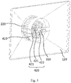
figure 5 , in this embodiment, thecooking device 10 further includes afan cover 410 and a fixedrack 420. The axis direction of theimpeller 210 is oriented towards theair return port 132. Thefan cover 410 is disposed on the fixedrack 420, and is disposed between theimpeller 210 and thepartition plate 130. The fixedrack 420 is fixed on theback housing 120. The supportingshaft 310 is fixed on the fixedrack 420. The heated air in thecooking cavity 101 is guided to flow from theair return port 132 to theimpeller 210 by setting thefan cover 410, which enables the air inside theimpeller 210 to fully exchange heat with theheating element 220, which realizes quick raise of temperature of the air. - In other embodiments, the fixed
rack 420 may be fixed on thepartition plate 130, which is not limited herein. - In this embodiment, the fixed
rack 420 includes two fixedlinks 421 and a connectingblock 422. The fixedlinks 421 are in U shapes. Two ends of each of the fixedlinks 421 are fixed on theback housing 120. The twofixed links 421 pass through thefan cover 410 and are arranged at intervals. A rotation shaft (not shown in figures) of theimpeller 210 is disposed in an interval region between the twofixed links 421. The connectingblock 422 connects two fixedlinks 421 in the location of the rotation shaft of theimpeller 210. The supportingshaft 310 is fixed on the connectingblock 422. Thefan cover 410 and the supportingshaft 310 are fixed through the two fixed links 241 arranged at intervals and the connecting blocks 422. A blocking region of the air flown from theair return port 132 to theimpeller 210 is decreased, which makes the air flow more smoothly. - In the embodiment, a width of a cross section of the
back housing 120 along the axis direction of theimpeller 210 is gradually enlarged along a direction approaching thefront housing 110. An end face of one end of theback housing 120 away from thefront housing 110 could be round. A diameter of the round end face is greater than or equal to the diameter of theimpeller 210, so as to match the shape of theimpeller 210. An edge of one end of theback housing 120 approaching thefront housing 110 is disposed in a rectangle shape. A length and a width of the edges of the rectangle are respectively greater than or equal to a length and a width of thepartition plate 130, so as to match the shape of thepartition plate 130. Through the arrangement of disposing theback housing 120 to the above-mentioned structure, an air passage of the heated air is compressed, a contact region of theback housing 120 and the heated air is decreased. In this way, the heated air in theair supply cavity 102 enters thecooking cavity 101 quickly, so as to further reduce heat loss, in the same time make the entire structure of thecooking device 10 more compact. - The above are only some embodiments of the present disclosure, and do not limit the scope of the present disclosure. Any equivalent structure or equivalent process transformation made using the content of the specification and drawings of the present disclosure, or directly or indirectly applied to other related technical fields, is also included in the scope of protection of the present disclosure.
Claims (16)
- A cooking device, comprising:a housing, wherein the housing comprises a front housing, a back housing, and a partition plate, the partition plate cooperates with the front housing to form a cooking cavity, the partition plate cooperates with the back housing to form an air supply cavity, and an air supply port and an air return port are defined on the partition plate for communicating the cooking cavity with the air supply cavity; anda heating and air-supplying assembly, disposed in the air supply cavity, wherein the heating and air-supplying assembly is configured to supply heated air to the cooking cavity through the air supply port, and the heated air in the cooking cavity further reflows to the air supply cavity through the air return port;wherein the heating and air-supplying assembly comprises an impeller and a heating element, the impeller is configured to drive air in the air supply cavity to flow, and the heating element is disposed in the impeller and configured to heat the air that flows into the impeller to form the heated air.
- The cooking device as claimed in claim 1, wherein the impeller is configured to draw the air along an axial direction of the impeller and eject the air along a radial direction of the impeller, and the heating element is configured to heat the air that flows into the impeller along the axial direction of the impeller.
- The cooking device as claimed in claim 2, wherein the air supply port is defined in a surrounding region of the partition plate, the air return port is defined in a middle region of the partition plate, and the impeller is disposed correspondingly to the air return port.
- The cooking device as claimed in claim 1, wherein the air supply port is defined in a middle region of the partition plate, the air return port is defined in a surrounding region of the partition plate, the impeller is disposed correspondingly to the air supply port, and the impeller is configured to draw the air from the air return port along a radial direction of the impeller, and eject the air from the air supply port along an axial direction of the impeller.
- The cooking device as claimed in claim 2, further comprising a supporting rack, wherein the supporting rack comprises a supporting shaft and a plurality of supporting pieces, the supporting shaft is disposed in the impeller along the axial direction of the impeller, the supporting pieces are disposed on the supporting shaft at intervals along a circumferential direction of the impeller and extend along the radial direction of the impeller, and the heating element is disposed on the supporting pieces.
- The cooking device as claimed in claim 5, wherein the heating element is a heating strip, and the heating strip surrounds a periphery of the supporting shaft in a heliciform and passes through and is fixed on the supporting pieces.
- The cooking device as claimed in claim 6, wherein the supporting pieces defined a plurality of through holes configured for the heating strip passing through, and a hole pitch between every two adjacent through holes defined along the axial direction of the impeller is 2 to 5 times a diameter of the heating strip.
- The cooking device as claimed in claim 7, wherein the heating strip is made of a resistance material, the diameter of the heating strip is in a range of 0.5mm to 1mm, and the supporting rack is made of an isolation material.
- The cooking device as claimed in claim 7, wherein the through holes are further divided into at least two rows at intervals along the radial direction of the impeller, and the through holes of every two adjacent rows of the through holes are further staggered with each other along the axial direction of the impeller.
- The cooking device as claimed in claim 9, wherein a row-to-row distance of the every two adjacent rows of the through holes along the radial direction of the impeller is 5 to 10 times the diameter of the heating strip.
- The cooking device as claimed in claim 5, wherein the heating element is a heating sheet, and the heating sheet is attached to the supporting pieces.
- The cooking device as claimed in claim 5, wherein the supporting shaft and the impeller are arranged coaxially.
- The cooking device as claimed in claim 5, wherein a distance between the supporting pieces and the impeller is greater than or equal to 2mm.
- The cooking device as claimed in claim 5, further comprising a fan cover and a fixed rack, the axial direction of the impeller is oriented towards the air return port, the fan cover is disposed on the fixed rack and between the impeller and the partition plate, to guide the heated air in the cooking cavity to flow from the air return port to the impeller, the fixed rack is fixed on the back housing or the partition plate, and the supporting shaft is fixed on the fixed rack.
- The cooking device as claimed in claim 1, wherein a width of a cross section of the back housing along an axial direction of the impeller is gradually enlarged along a direction of approaching the front housing.
- The cooking device as claimed in claim 1, wherein the impeller is a centrifugal impeller.
Applications Claiming Priority (2)
| Application Number | Priority Date | Filing Date | Title |
|---|---|---|---|
| CN202010701891.9A CN111904293B (en) | 2020-07-17 | 2020-07-17 | Cooking device |
| PCT/CN2020/130159 WO2022011912A1 (en) | 2020-07-17 | 2020-11-19 | Cooking device |
Publications (2)
| Publication Number | Publication Date |
|---|---|
| EP4011252A1 true EP4011252A1 (en) | 2022-06-15 |
| EP4011252A4 EP4011252A4 (en) | 2022-11-23 |
Family
ID=73280485
Family Applications (1)
| Application Number | Title | Priority Date | Filing Date |
|---|---|---|---|
| EP20945414.9A Pending EP4011252A4 (en) | 2020-07-17 | 2020-11-19 | COOKING DEVICE |
Country Status (4)
| Country | Link |
|---|---|
| US (1) | US20220214048A1 (en) |
| EP (1) | EP4011252A4 (en) |
| CN (1) | CN111904293B (en) |
| WO (1) | WO2022011912A1 (en) |
Families Citing this family (6)
| Publication number | Priority date | Publication date | Assignee | Title |
|---|---|---|---|---|
| CN111904293B (en) * | 2020-07-17 | 2022-04-01 | 广东美的白色家电技术创新中心有限公司 | Cooking device |
| US12140320B2 (en) * | 2020-07-29 | 2024-11-12 | Electrolux Home Products, Inc. | Oven cavity wrapper having a structural embossment and associated convection features |
| CN114668302A (en) * | 2020-12-24 | 2022-06-28 | 广东美的白色家电技术创新中心有限公司 | Heating and cooking equipment |
| CN112656246B (en) * | 2020-12-31 | 2024-05-17 | 广东美的厨房电器制造有限公司 | Cooking device |
| CN113080719B (en) * | 2021-04-29 | 2022-04-22 | 广东美的厨房电器制造有限公司 | Cooking utensil |
| WO2024193602A1 (en) * | 2023-03-20 | 2024-09-26 | 广东美的厨房电器制造有限公司 | Heating assembly and cooking appliance |
Family Cites Families (25)
| Publication number | Priority date | Publication date | Assignee | Title |
|---|---|---|---|---|
| US5414794A (en) * | 1993-10-26 | 1995-05-09 | Shao; Steve | Quickly-mountable securing structure for electric heating element in a heater fan |
| GB2286455B (en) * | 1994-02-10 | 1998-01-14 | Stoves Plc | Improvements in and relating to gaseous fuel burner assemblies and to appliances incorporating such burner assemblies |
| US5468935A (en) * | 1994-12-10 | 1995-11-21 | Wang; Ching-Hsiang | L-electric conventional roaster oven with whirlpool air circulation |
| US20040089648A1 (en) * | 2002-07-29 | 2004-05-13 | Griffey Dean J. | Open coil heater element convection system for convection ovens and the like |
| FR2849162A1 (en) * | 2002-12-23 | 2004-06-25 | Premark Feg Llc | Oven for cooking food, has vane connected to rotation axis such that air coming from air inlet penetrates directly inside circular trajectory of vane before being expelled into rest of chamber space |
| SE525827C2 (en) * | 2003-09-08 | 2005-05-10 | Whirlpool Co | Microwave oven with convection heating |
| DE102004033374A1 (en) * | 2004-07-09 | 2006-02-16 | BSH Bosch und Siemens Hausgeräte GmbH | A heating element construction for the recirculation fan in a domestic oven has a circular insulated former for heating wire or metallic strip surrounding the fan |
| US20120017773A1 (en) * | 2008-08-18 | 2012-01-26 | Spinfry, Inc. | Fryer device with oil removal and conveyor system |
| CN204663927U (en) * | 2015-03-31 | 2015-09-23 | 罗祯美 | Circulation fan with heating function |
| CN205006603U (en) * | 2015-06-15 | 2016-02-03 | 李坚南 | Cooking device with hidden hot air heating component |
| CN210784022U (en) * | 2015-12-07 | 2020-06-19 | 皇家飞利浦有限公司 | Air-based fryer apparatus |
| KR102475320B1 (en) * | 2016-04-26 | 2022-12-08 | 삼성전자주식회사 | Electric oven |
| CN205641043U (en) * | 2016-05-19 | 2016-10-12 | 广东美的厨房电器制造有限公司 | Microwave cooking device |
| CN106264187A (en) * | 2016-09-30 | 2017-01-04 | 广东美的厨房电器制造有限公司 | cooking appliance |
| CN206300225U (en) * | 2016-12-02 | 2017-07-04 | 广东美的厨房电器制造有限公司 | Drawer-type microwave oven |
| CN107019411B (en) * | 2017-05-10 | 2022-06-28 | 佛山市顺德区龙江镇旗龙电器有限公司 | Multifunctional cooker |
| CN107289472A (en) * | 2017-06-15 | 2017-10-24 | 广东美的厨房电器制造有限公司 | Cooking apparatus |
| JP7397078B2 (en) * | 2018-07-18 | 2023-12-12 | ガンマ ソチエタ ペル アツィオニ | Air heating device for a hair dryer, blowing device for a hair dryer, and hair dryer including said device |
| JP7149501B2 (en) * | 2019-01-10 | 2022-10-07 | パナソニックIpマネジメント株式会社 | heating cooker |
| CN109793430B (en) * | 2019-01-31 | 2024-01-02 | 青岛海氏烘焙电器有限公司 | Oven with air frying function |
| CN210611905U (en) * | 2019-06-04 | 2020-05-26 | 宁波市悦达电子科技有限公司 | Effectual food processor of heated air circulation |
| CN210871132U (en) * | 2019-07-05 | 2020-06-30 | 广东云禾智能科技有限公司 | Air frying pan |
| CN110974050B (en) * | 2019-12-31 | 2021-06-29 | 广东美的厨房电器制造有限公司 | Hot air assembly and heating device having the same |
| CN111329363A (en) * | 2020-04-26 | 2020-06-26 | 深圳玛克餐饮设备有限公司 | Baking oven |
| CN111904293B (en) * | 2020-07-17 | 2022-04-01 | 广东美的白色家电技术创新中心有限公司 | Cooking device |
-
2020
- 2020-07-17 CN CN202010701891.9A patent/CN111904293B/en active Active
- 2020-11-19 EP EP20945414.9A patent/EP4011252A4/en active Pending
- 2020-11-19 WO PCT/CN2020/130159 patent/WO2022011912A1/en not_active Ceased
-
2022
- 2022-03-24 US US17/703,917 patent/US20220214048A1/en not_active Abandoned
Also Published As
| Publication number | Publication date |
|---|---|
| US20220214048A1 (en) | 2022-07-07 |
| EP4011252A4 (en) | 2022-11-23 |
| CN111904293A (en) | 2020-11-10 |
| CN111904293B (en) | 2022-04-01 |
| WO2022011912A1 (en) | 2022-01-20 |
Similar Documents
| Publication | Publication Date | Title |
|---|---|---|
| EP4011252A1 (en) | Cooking device | |
| US6526961B1 (en) | Conveyor oven | |
| CN108354466B (en) | Cooking device fan and cooking device | |
| EP2636955B1 (en) | A cooking oven provided for heat transfer by convection | |
| AU2001273588A1 (en) | Conveyor oven | |
| US6541746B2 (en) | Microwave oven with a convectional heating apparatus | |
| CN110313217B (en) | Convection Systems for RF Ovens | |
| CN110234932A (en) | For carrying out the system of cleaning circulation oven air with reduced heat damage | |
| EP3548810B1 (en) | Air cleaning system for an oven with reduced thermal disruption | |
| EP2436984B1 (en) | Heating device | |
| CN112515493A (en) | Cooking utensil | |
| KR20040088031A (en) | Oven with forced air circulation | |
| DE102011006075A1 (en) | Cooking apparatus i.e. hearth-baking oven combination, for use as kitchen furniture, has exhaust air system guided around two side surfaces of cooking chamber and opening into discharge opening below door that is provided with aperture | |
| CN221060449U (en) | Cooking apparatus | |
| CN215959453U (en) | Hot air assembly and cooking device | |
| CN113749529A (en) | Air oven with heated air circulation heating system | |
| CN219639128U (en) | Centrifugal air duct type volute assembly of air fryer | |
| CN220713697U (en) | Cooking Equipment | |
| JPH06103099B2 (en) | Hot air circulation cooker | |
| CN223158265U (en) | Desk-top and embedded dual-purpose heat dissipation wind channel structure | |
| CN220713700U (en) | Cooking Equipment | |
| CN220859921U (en) | Cooking apparatus | |
| EP3253216B1 (en) | Cooking apparatus | |
| CN221077125U (en) | Drying equipment and guipure stove | |
| CN223929994U (en) | Cooking apparatus |
Legal Events
| Date | Code | Title | Description |
|---|---|---|---|
| STAA | Information on the status of an ep patent application or granted ep patent |
Free format text: STATUS: THE INTERNATIONAL PUBLICATION HAS BEEN MADE |
|
| PUAI | Public reference made under article 153(3) epc to a published international application that has entered the european phase |
Free format text: ORIGINAL CODE: 0009012 |
|
| STAA | Information on the status of an ep patent application or granted ep patent |
Free format text: STATUS: REQUEST FOR EXAMINATION WAS MADE |
|
| 17P | Request for examination filed |
Effective date: 20220310 |
|
| AK | Designated contracting states |
Kind code of ref document: A1 Designated state(s): AL AT BE BG CH CY CZ DE DK EE ES FI FR GB GR HR HU IE IS IT LI LT LU LV MC MK MT NL NO PL PT RO RS SE SI SK SM TR |
|
| A4 | Supplementary search report drawn up and despatched |
Effective date: 20221026 |
|
| RIC1 | Information provided on ipc code assigned before grant |
Ipc: F24C 15/32 20060101ALI20221020BHEP Ipc: A47J 37/06 20060101AFI20221020BHEP |
|
| DAV | Request for validation of the european patent (deleted) | ||
| DAX | Request for extension of the european patent (deleted) | ||
| STAA | Information on the status of an ep patent application or granted ep patent |
Free format text: STATUS: EXAMINATION IS IN PROGRESS |
|
| 17Q | First examination report despatched |
Effective date: 20260206 |