EP4010615B1 - Circumferentially-sectioned valve cages - Google Patents
Circumferentially-sectioned valve cages Download PDFInfo
- Publication number
- EP4010615B1 EP4010615B1 EP20800372.3A EP20800372A EP4010615B1 EP 4010615 B1 EP4010615 B1 EP 4010615B1 EP 20800372 A EP20800372 A EP 20800372A EP 4010615 B1 EP4010615 B1 EP 4010615B1
- Authority
- EP
- European Patent Office
- Prior art keywords
- cage
- section
- valve
- cage section
- sections
- Prior art date
- Legal status (The legal status is an assumption and is not a legal conclusion. Google has not performed a legal analysis and makes no representation as to the accuracy of the status listed.)
- Active
Links
Images








Classifications
-
- F—MECHANICAL ENGINEERING; LIGHTING; HEATING; WEAPONS; BLASTING
- F16—ENGINEERING ELEMENTS AND UNITS; GENERAL MEASURES FOR PRODUCING AND MAINTAINING EFFECTIVE FUNCTIONING OF MACHINES OR INSTALLATIONS; THERMAL INSULATION IN GENERAL
- F16K—VALVES; TAPS; COCKS; ACTUATING-FLOATS; DEVICES FOR VENTING OR AERATING
- F16K3/00—Gate valves or sliding valves, i.e. cut-off apparatus with closing members having a sliding movement along the seat for opening and closing
- F16K3/30—Details
-
- F—MECHANICAL ENGINEERING; LIGHTING; HEATING; WEAPONS; BLASTING
- F16—ENGINEERING ELEMENTS AND UNITS; GENERAL MEASURES FOR PRODUCING AND MAINTAINING EFFECTIVE FUNCTIONING OF MACHINES OR INSTALLATIONS; THERMAL INSULATION IN GENERAL
- F16K—VALVES; TAPS; COCKS; ACTUATING-FLOATS; DEVICES FOR VENTING OR AERATING
- F16K47/00—Means in valves for absorbing fluid energy
- F16K47/08—Means in valves for absorbing fluid energy for decreasing pressure or noise level and having a throttling member separate from the closure member, e.g. screens, slots, labyrinths
-
- F—MECHANICAL ENGINEERING; LIGHTING; HEATING; WEAPONS; BLASTING
- F16—ENGINEERING ELEMENTS AND UNITS; GENERAL MEASURES FOR PRODUCING AND MAINTAINING EFFECTIVE FUNCTIONING OF MACHINES OR INSTALLATIONS; THERMAL INSULATION IN GENERAL
- F16K—VALVES; TAPS; COCKS; ACTUATING-FLOATS; DEVICES FOR VENTING OR AERATING
- F16K27/00—Construction of housing; Use of materials therefor
- F16K27/04—Construction of housing; Use of materials therefor of sliding valves
- F16K27/041—Construction of housing; Use of materials therefor of sliding valves cylindrical slide valves
-
- F—MECHANICAL ENGINEERING; LIGHTING; HEATING; WEAPONS; BLASTING
- F16—ENGINEERING ELEMENTS AND UNITS; GENERAL MEASURES FOR PRODUCING AND MAINTAINING EFFECTIVE FUNCTIONING OF MACHINES OR INSTALLATIONS; THERMAL INSULATION IN GENERAL
- F16K—VALVES; TAPS; COCKS; ACTUATING-FLOATS; DEVICES FOR VENTING OR AERATING
- F16K3/00—Gate valves or sliding valves, i.e. cut-off apparatus with closing members having a sliding movement along the seat for opening and closing
- F16K3/22—Gate valves or sliding valves, i.e. cut-off apparatus with closing members having a sliding movement along the seat for opening and closing with sealing faces shaped as surfaces of solids of revolution
- F16K3/24—Gate valves or sliding valves, i.e. cut-off apparatus with closing members having a sliding movement along the seat for opening and closing with sealing faces shaped as surfaces of solids of revolution with cylindrical valve members
- F16K3/246—Combination of a sliding valve and a lift valve
-
- F—MECHANICAL ENGINEERING; LIGHTING; HEATING; WEAPONS; BLASTING
- F16—ENGINEERING ELEMENTS AND UNITS; GENERAL MEASURES FOR PRODUCING AND MAINTAINING EFFECTIVE FUNCTIONING OF MACHINES OR INSTALLATIONS; THERMAL INSULATION IN GENERAL
- F16K—VALVES; TAPS; COCKS; ACTUATING-FLOATS; DEVICES FOR VENTING OR AERATING
- F16K3/00—Gate valves or sliding valves, i.e. cut-off apparatus with closing members having a sliding movement along the seat for opening and closing
- F16K3/22—Gate valves or sliding valves, i.e. cut-off apparatus with closing members having a sliding movement along the seat for opening and closing with sealing faces shaped as surfaces of solids of revolution
- F16K3/24—Gate valves or sliding valves, i.e. cut-off apparatus with closing members having a sliding movement along the seat for opening and closing with sealing faces shaped as surfaces of solids of revolution with cylindrical valve members
- F16K3/26—Gate valves or sliding valves, i.e. cut-off apparatus with closing members having a sliding movement along the seat for opening and closing with sealing faces shaped as surfaces of solids of revolution with cylindrical valve members with fluid passages in the valve member
- F16K3/262—Gate valves or sliding valves, i.e. cut-off apparatus with closing members having a sliding movement along the seat for opening and closing with sealing faces shaped as surfaces of solids of revolution with cylindrical valve members with fluid passages in the valve member with a transverse bore in the valve member
Definitions
- This disclosure relates generally to valve cages and, more particularly, to circumferentially-sectioned valve cages.
- Valves commonly include a valve body defining a fluid pathway having an inlet and outlet.
- a plug located within the valve body is movable relative to a seat ring located within the valve body to control the flow of a fluid through the valve body and/or along the fluid pathway.
- the flow of the fluid through the valve body and/or along the fluid pathway is further controlled and/or impacted via a cage located within the valve body.
- the cage typically has a cylindrical, single-piece (e.g., joint-free) shape and/or configuration, with the cage being arranged within the valve body such that a sidewall of the cage circumscribes the plug.
- the sidewall of the cage includes a plurality of fluid passages and/or openings (e.g., through-holes) arranged in a spaced relationship about the sidewall and/or around the circumference of the cage.
- Fluid flowing through the valve body and/or along the fluid pathway of the valve passes from the inlet of the valve body, through the seat ring, through one or more of the openings of the sidewall of the cage, and toward the outlet of the valve body.
- the arrangement and/or orientation of the openings about the sidewall and/or around the circumference of the cage impacts the flow characteristics of the fluid passing through the valve body and/or along the fluid pathway, including the rate at which the fluid passes through the valve body and/or along the fluid pathway.
- US 4,356,843 A shows a lamellate fluid resistance device which may be part of fluid systems to dissipate moderate pressure differentials.
- Ring-shaped plates are removably stacked one over the other to form a circumference.
- a ring portion of each plate is removed to provide a wedge-shaped opening in the circumference.
- Each successive plate is rotatively displaced to the adjacent one displacing also the wedge-shaped openings relative to each other.
- Example circumferentially-sectioned valve cages are shown.
- an apparatus is shown.
- the apparatus comprises a plurality of cage sections collectively configured to be removably coupled together to form a valve cage having a circumference and a plurality of joints.
- the joints correspond in number to the cage sections and are spaced apart from one another about the circumference.
- respective ones of the joints are defined by neighboring ones of the cage sections.
- a valve cage with the features of claim 1 is provided.
- a valve in some examples, comprises a valve body and a valve cage located within the valve body.
- Descriptors "first,” “second,” “third,” etc. are used herein when identifying multiple elements or components which may be referred to separately. Unless otherwise specified or understood based on their context of use, such descriptors are not intended to impute any meaning of priority or ordering in time but merely as labels for referring to multiple elements or components separately for ease of understanding the disclosed examples.
- the descriptor "first” may be used to refer to an element in the detailed description, while the same element may be referred to in a claim with a different descriptor such as "second” or “third.” In such instances, it should be understood that such descriptors are used merely for ease of referencing multiple elements or components.
- single-piece refers to a unitary, one-piece component that is free of joints held together via welding or other mechanical coupling, joining and/or fastening components.
- first component e.g., a first cage section of a valve cage
- second component e.g., a second cage section of the valve cage
- removably coupled means the first component is coupled, joined, connected and/or fastened to the second component via one or more coupling, joining, connecting and/or fastening component(s) in a non-permanent manner that enables the first component to subsequently be uncoupled, unjoined, unconnected and/or unfastened from the second component without damaging and/or destroying the coupling, joining, connecting and/or fastening component(s).
- additive manufacturing refers generally to a process by which three-dimensional design data (e.g., a computer-aided design (CAD) file) is used in conjunction with a controllable laser to fabricate an object by depositing successive layers of material on top of one another.
- CAD computer-aided design
- additive manufacturing fabricates the object layer by layer using one or more material(s) in the form of a fine powder (e.g., a metallic powder, a plastic powder, a composite powder, etc.) capable of being solidified by application of the laser thereto.
- valve cages typically have a cylindrical, single-piece (e.g., joint-free) shape that is sized and/or configured to facilitate centrally locating a cylindrical valve plug within the valve cage, such that a sidewall of the valve cage circumscribes the valve plug.
- the sidewall of the valve cage includes a plurality of fluid passages and/or openings (e.g., through-holes) arranged in a spaced relationship about the sidewall and/or around the circumference of the cage.
- the known single-piece valve cages described above have traditionally been fabricated using a variety of casting, molding, milling, forging and/or drilling processes and/or techniques. More recently, consideration has been given to fabricating single-piece valve cages via additive manufacturing processes and/or techniques that have commercially evolved. Regardless of the chosen process, challenges and/or constraints often arise when the single-piece valve cage for which fabrication is desired has a relatively large size (e.g., a diameter exceeding 45,7 centimetre (18 inches)). For example, conventional tooling and/or molds become more complex and/or more costly as the desired size of the single-piece valve cage increases. As another example, most commercially available 3D-printer systems that facilitate additive manufacturing have build envelopes and/or build platforms that prevent and/or prohibit the ability to fabricate a relatively large single-piece valve cage.
- example valve cages disclosed herein are circumferentially sectioned. More specifically, example valve cages disclosed herein include a plurality of cage sections that are removably couplable to one another to form a circumference of the valve cage. When assembled (e.g., when the cage sections are removably coupled to one another), the example circumferentially-sectioned valve cages disclosed herein include joints corresponding in number to the cage sections, with the joints being spaced apart from one another about the circumference of the valve cage, and respective ones of the joints being defined by neighboring ones of the cage sections. In some examples, the example circumferentially-sectioned valve cages disclosed herein have a diameter exceeding eighteen inches (45,7 cm).
- FIG. 1 is a plan view of a first example valve cage 100.
- FIG. 2 is a side view of the valve cage 100 of FIG. 1 .
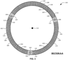
- FIG. 3 is a cross-sectional view of the valve cage 100 of FIGS. 1 and 2 taken along section A-A of FIG. 2 .
- the valve cage 100 of FIGS. 1-3 is a circumferentially-sectioned valve cage having an example circumference 102 formed by a plurality of example cage sections 104 that are removably coupled to one another via example pins 106, as further described below.
- the diameter of the valve cage 100 of FIGS. 1-3 may exceed eighteen inches (45,7 cm).
- Each cage section 104 of the valve cage 100 of FIGS. 1-3 is fabricated using an additive manufacturing process, with each resultant cage section 104 being integrally formed as a single-piece structure having the features described herein.
- respective ones of the cage sections 104 of the valve cage 100 of FIGS. 1-3 are fabricated within a common build envelope and/or on a common build platform of a 3D-printer system during a single build performed using an additive manufacturing process.
- each of the cage sections 104 is fabricated such that first ends of the cage sections 104 are aligned with one another within the build envelope and/or on the build platform, second ends of the cage sections 104 are aligned with one another within the build envelope and/or on the build platform, and curvatures of the cage sections 104 extending between the first and second ends of the cage sections 104 are commonly oriented within the build envelope and/or on the build platform.
- one or more of the cage sections 104 of the valve cage 100 of FIGS. 1-3 may alternatively be fabricated using one or more casting, molding, milling, forging and/or drilling processes, with each resultant cage section 104 being integrally formed as a single-piece structure having the features described herein.
- each cage section 104 includes a plurality of example openings 202 (e.g., through-holes) formed in and extending through an example sidewall 108 of the cage section 104.
- the openings 202 of each sidewall 108 are configured to enable fluid to pass through the sidewall 108 (e.g., from an outer surface of the sidewall 108 to an inner surface of the sidewall 108).
- the openings 202 can be formed and/or configured as passages of any size, shape, geometry and/or pattern that enable fluid to pass through the sidewall 108. In the illustrated example of FIGS.
- the sidewalls 108 and/or, more generally, the cage sections 104 of the valve cage 100 define a cylindrical shape having an example central axis 110 and a circular cross-section perpendicular to the central axis 110.
- the sidewalls 108 and/or, more generally, the cage sections 104 of the valve cage 100 may alternatively define a cylindrical shape having an oval or elliptical cross-section perpendicular to the central axis 110.
- the valve cage 100 of FIGS. 1-3 further includes a plurality of example joints 112.
- the joints 112 correspond in number to the cage sections 104, and are spaced apart from one another about the circumference 102 of the valve cage 100 at locations defined by neighboring ones of the cage sections 104.
- the joints 112 of the valve cage 100 extend along an example axial direction 204 defined by and/or parallel to the central axis 110 of the valve cage 100.
- the joints 112 of the valve cage 100 may alternatively extend in a direction that lies at a non-parallel angle relative to the central axis 110 of the valve cage 100.
- the cage sections 104 of the valve cage 100 include a first example cage section 114, a second example cage section 116, and a third example cage section 118.
- the pins 106 of the valve cage 100 include a first example pin 120, a second example pin 122, and a third example pin 124.
- the joints 112 of the valve cage 100 include a first example joint 126, a second example joint 128, and a third example joint 130.
- the first cage section 114 is removably coupled to the second cage section 116 at the first joint 126 via the first pin 120, and is further removably coupled to the third cage section 118 at the third joint 130 via the third pin 124.
- the second cage section 116 is removably coupled to the third cage section 118 at the second joint 128 via the second pin 122, and is further removably coupled to the first cage section 114 at the first joint 126 via the first pin 120.
- the third cage section 118 is removably coupled to the first cage section 114 at the third joint 130 via the third pin 124, and is further removably coupled to the second cage section 116 at the second joint 128 via the second pin 122.
- Each of the first, second and third cage sections 114, 116, 118 of the valve cage 100 of FIGS. 1-3 has an arc length (e.g., measured along an outer surface of the sidewall 108) equal to approximately one-third of the circumference 102 of the valve cage 100.
- the first, second and third cage sections 114, 116, 118 of the valve cage 100 are uniformly distributed (e.g., equally spaced) about the circumference 102 of the valve cage 100 relative to the central axis 110 of the valve cage 100.
- the first, second and third joints 126, 128, 130 of the valve cage 100 are also uniformly distributed (e.g., equally spaced) about the circumference 102 of the valve cage 100 relative to the central axis 110 of the valve cage 100.
- the valve cage 100 includes three (3) uniformly-distributed cage sections 104 and three uniformly-distributed (3) joints 112, with each of the three (3) cage sections 104 having an arc length equal to approximately one-third of the circumference 102 of the valve cage 100.
- valve cage 100 of FIGS. 1-3 may include a different number of cage sections 104 and a different corresponding number of joints 112 relative to the number of cage sections 104 and joints 112 shown in FIGS. 1-3 .
- the valve cage 100 of FIGS. 1-3 can alternatively be configured to include only two (2) uniformly-distributed cage sections 104 and only two (2) uniformly-distributed joints 112, with each of the two (2) cage sections 104 having an arc length equal to approximately one-half of the circumference 102 of the valve cage 100.
- 1-3 can alternatively be configured to include four (4) uniformly-distributed cage sections 104 and four (4) uniformly-distributed joints 112, with each of the four (4) cage sections 104 having an arc length equal to approximately one-fourth of the circumference 102 of the valve cage 100.
- the valve cage 100 may include cage sections 104 that are not uniformly distributed, and/or that have differing arc lengths.
- the valve cage 100 of FIGS. 1-3 can alternatively be configured to include two (2) non-uniformly-distributed cage sections 104 and two (2) non-uniformly-distributed joints 112, with a first one of the two (2) cage sections 104 having an arc length equal to approximately one-third of the circumference 102 of the valve cage 100, and a second one of the two (2) cage sections 104 having an arc length equal to approximately two-thirds of the circumference 102 of the valve cage 100.
- 1-3 can alternatively be configured to include three (3) non-uniformly-distributed cage sections 104 and three (3) non-uniformly-distributed joints 112, with a first one of the three (3) cage sections 104 having an arc length equal to approximately one-fourth of the circumference 102 of the valve cage 100, a second one of the three (3) cage sections 104 having an arc length equal to approximately one-fourth of the circumference 102 of the valve cage 100, and a third one of the three (3) cage sections 104 having an arc length equal to approximately one-half of the circumference 102 of the valve cage 100.
- FIG. 4 is an isolated perspective view of the first cage section 114 of the valve cage 100 of FIGS. 1-3 .
- the second cage section 116 and the third cage section 118 of the valve cage 100 of FIGS. 1-3 are structured and/or configured in a manner that is substantially identical to that of the first cage section 114 shown and described in connection with FIG. 4 .
- the first cage section 114 includes a first example end 402 and a second example end 404 located opposite the first end 402.
- First example arms 406 are formed and/or located at the first end 402 of the first cage section 114 such that the first arms 406 extend circumferentially away from the first end 402 of the first cage section 114.
- Respective ones of the first arms 406 are axially spaced apart from one another (e.g., along the axial direction 204 of FIG. 2 ).
- Each of the first arms 406 includes a first example axially-oriented opening 408 (e.g., a bore or through-hole extending along the axial direction 204 of FIG. 2 ).
- Respective ones of the first arms 406 are axially aligned with one another (e.g., along the axial direction 204 of FIG. 2 ), as are respective ones of the first axially-oriented openings 408.
- second example arms 410 are formed and/or located at the second end 404 of the first cage section 114 such that the second arms 410 extend circumferentially away from the second end 404 of the first cage section 114. Respective ones of the second arms 410 are axially spaced apart from one another (e.g., along the axial direction 204 of FIG. 2 ). Each of the second arms 410 includes a second example axially-oriented opening 412 (e.g., a bore or through-hole extending along the axial direction 204 of FIG. 2 ). Respective ones of the second arms 410 are axially aligned with one another (e.g., along the axial direction 204 of FIG. 2 ), as are respective ones of the second axially-oriented openings 412.
- the first cage section 114 of the valve cage 100 is structured and/or configured such that the respective axial locations of the second arms 410 of the first cage section 114 are staggered and/or offset relative to the respective axial locations of the first arms 406 of the first cage section 114.
- the second cage section 116 and the third cage section 118 are structured and/or configured in a substantially identical manner, thereby enabling the first arms 406 of the first cage section 114 shown in FIG. 4 to be interleaved with the second arms 410 of the second cage section 116 of the valve cage 100, further enabling the second arms 410 of the first cage section 114 shown in FIG.
- the first axially-oriented openings 408 of the first arms 406 of the first cage section 114 are axially aligned with the second axially-oriented openings 412 of the second arms 410 of the second cage section 116.
- Axial alignment between the first axially-oriented openings 408 of the first arms 406 of the first cage section 114 and the second axially-oriented openings 412 of the second arms 410 of the second cage section 116 enables the first pin 120 to be disposed through and/or within respective ones of the aligned axially-oriented openings. When so disposed, the first pin 120 removably couples the first cage section 114 to the second cage section 116.
- the first axially-oriented openings 408 of the first arms 406 of the second cage section 116 are axially aligned with the second axially-oriented openings 412 of the second arms 410 of the third cage section 118.
- Axial alignment between the first axially-oriented openings 408 of the first arms 406 of the second cage section 116 and the second axially-oriented openings 412 of the second arms 410 of the third cage section 118 enables the second pin 122 to be disposed through and/or within respective ones of the aligned axially-oriented openings.
- the second pin 122 removably couples the second cage section 116 to the third cage section 118.
- the first axially-oriented openings 408 of the first arms 406 of the third cage section 118 are axially aligned with the second axially-oriented openings 412 of the second arms 410 of the first cage section 114.
- Axial alignment between the first axially-oriented openings 408 of the first arms 406 of the third cage section 118 and the second axially-oriented openings 412 of the second arms 410 of the first cage section 114 enables the third pin 124 to be disposed through and/or within respective ones of the aligned axially-oriented openings. When so disposed, the third pin 124 removably couples the third cage section 118 to the first cage section 114.
- FIG. 5 is a plan view of a second example valve cage 500.
- FIG. 6 is a side view of the valve cage 500 of FIG. 5 .
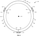
- FIG. 7 is a cross-sectional view of the valve cage 500 of FIGS. 5 and 6 taken along section B-B of FIG. 6 .
- the valve cage 500 of FIGS. 5-7 is a circumferentially-sectioned valve cage having an example circumference 502 formed by a plurality of example cage sections 504 that are removably coupled to one another via example bolts 506, as further described below.
- the diameter of the valve cage 500 of FIGS. 5-7 may exceed eighteen inches (45,7 cm).
- Each cage section 504 of the valve cage 500 of FIGS. 5-7 is fabricated using an additive manufacturing process, with each resultant cage section 504 being integrally formed as a single-piece structure having the features described herein.
- respective ones of the cage sections 504 of the valve cage 500 of FIGS. 5-7 are fabricated within a common build envelope and/or on a common build platform of a 3D-printer system during a single build performed using an additive manufacturing process.
- each of the cage sections 504 is fabricated such that first ends of the cage sections 504 are aligned with one another within the build envelope and/or on the build platform, second ends of the cage sections 504 are aligned with one another within the build envelope and/or on the build platform, and curvatures of the cage sections 504 extending between the first and second ends of the cage sections 504 are commonly oriented within the build envelope and/or on the build platform.
- one or more of the cage sections 504 of the valve cage 500 of FIGS. 5-7 may alternatively be fabricated using one or more casting, molding, milling, forging and/or drilling processes, with each resultant cage section 504 being integrally formed as a single-piece structure having the features described herein.
- each cage section 504 includes a plurality of example openings 602 (e.g., through-holes) formed in and extending through an example sidewall 508 of the cage section 504.
- the openings 602 of each sidewall 508 are configured to enable fluid to pass through the sidewall 508 (e.g., from an outer surface of the sidewall 508 to an inner surface of the sidewall 508).
- the openings 602 can be formed and/or configured as passages of any size, shape, geometry and/or pattern that enable fluid to pass through the sidewall 508. In the illustrated example of FIGS.
- the sidewalls 508 and/or, more generally, the cage sections 504 of the valve cage 500 define a cylindrical shape having an example central axis 510 and a circular cross-section perpendicular to the central axis 510.
- the sidewalls 508 and/or, more generally, the cage sections 504 of the valve cage 500 may alternatively define a cylindrical shape having an oval or elliptical cross-section perpendicular to the central axis 510.
- the valve cage 500 of FIGS. 5-7 further includes a plurality of example joints 512.
- the joints 512 correspond in number to the cage sections 504, and are spaced apart from one another about the circumference 502 of the valve cage 500 at locations defined by neighboring ones of the cage sections 504.
- the joints 512 of the valve cage 500 extend along an example axial direction 604 defined by and/or parallel to the central axis 510 of the valve cage 500.
- the joints 512 of the valve cage 500 may alternatively extend in a direction that lies at a non-parallel angle relative to the central axis 510 of the valve cage 500.
- the cage sections 504 of the valve cage 500 include a first example cage section 514, a second example cage section 516, and a third example cage section 518.
- the bolts 506 of the valve cage 500 include first example bolts 520, second example bolts 522, and third example bolts 524.
- the joints 512 of the valve cage 500 include a first example joint 526, a second example joint 528, and a third example joint 530.
- the first cage section 514 is removably coupled to the second cage section 516 at the first joint 526 via the first bolts 520, and is further removably coupled to the third cage section 518 at the third joint 530 via the third bolts 524.
- the second cage section 516 is removably coupled to the third cage section 518 at the second joint 528 via the second bolts 522, and is further removably coupled to the first cage section 514 at the first joint 526 via the first bolts 520.
- the third cage section 518 is removably coupled to the first cage section 514 at the third joint 530 via the third bolts 524, and is further removably coupled to the second cage section 516 at the second joint 528 via the second bolts 522.
- Each of the first, second and third cage sections 514, 516, 518 of the valve cage 500 of FIGS. 5-7 has an arc length (e.g., measured along an outer surface of the sidewall 508) equal to approximately one-third of the circumference 502 of the valve cage 500.
- the first, second and third cage sections 514, 516, 518 of the valve cage 500 are uniformly distributed (e.g., equally spaced) about the circumference 502 of the valve cage 500 relative to the central axis 510 of the valve cage 500.
- the first, second and third joints 526, 528, 530 of the valve cage 500 are also uniformly distributed (e.g., equally spaced) about the circumference 502 of the valve cage 500 relative to the central axis 510 of the valve cage 500.
- the valve cage 500 includes three (3) uniformly-distributed cage sections 504 and three uniformly-distributed (3) joints 512, with each of the three (3) cage sections 504 having an arc length equal to approximately one-third of the circumference 502 of the valve cage 500.
- valve cage 500 of FIGS. 5-7 may include a different number of cage sections 504 and a different corresponding number of joints 512 relative to the number of cage sections 504 and joints 512 shown in FIGS. 5-7 .
- the valve cage 500 of FIGS. 5-7 can alternatively be configured to include only two (2) uniformly-distributed cage sections 504 and only two (2) uniformly-distributed joints 512, with each of the two (2) cage sections 504 having an arc length equal to approximately one-half of the circumference 502 of the valve cage 500.
- each of the four (4) cage sections 504 having an arc length equal to approximately one-fourth of the circumference 502 of the valve cage 500.
- the valve cage 500 may include cage sections 504 that are not uniformly distributed, and/or that have differing arc lengths.
- the valve cage 500 of FIGS. 5-7 can alternatively be configured to include two (2) non-uniformly-distributed cage sections 504 and two (2) non-uniformly-distributed joints 512, with a first one of the two (2) cage sections 504 having an arc length equal to approximately one-third of the circumference 502 of the valve cage 500, and a second one of the two (2) cage sections 504 having an arc length equal to approximately two-thirds of the circumference 502 of the valve cage 500.
- 5-7 can alternatively be configured to include three (3) non-uniformly-distributed cage sections 504 and three (3) non-uniformly-distributed joints 512, with a first one of the three (3) cage sections 504 having an arc length equal to approximately one-fourth of the circumference 502 of the valve cage 500, a second one of the three (3) cage sections 504 having an arc length equal to approximately one-fourth of the circumference 502 of the valve cage 500, and a third one of the three (3) cage sections 504 having an arc length equal to approximately one-half of the circumference 502 of the valve cage 500.
- FIG. 8 is an isolated perspective view of the first cage section 514 of the valve cage 500 of FIGS. 5-7 .
- the second cage section 516 and the third cage section 518 of the valve cage 500 of FIGS. 5-7 are structured and/or configured in a manner that is substantially identical to that of the first cage section 514 shown and described in connection with FIG. 8 .
- the first cage section 514 includes a first example end 802 and a second example end 804 located opposite the first end 802.
- First example flanges 806 are formed and/or located at the first end 802 of the first cage section 514 such that the first flanges 806 extend outwardly from the sidewall 508 of the first cage section 514 proximate the first end 802 of the first cage section 514. Respective ones of the first flanges 806 are axially spaced apart from one another (e.g., along the axial direction 604 of FIG. 6 ). Each of the first flanges 806 includes a first example transversely-oriented opening 808 (e.g., a bore or through-hole extending in a direction transverse to the axial direction 604 of FIG. 6 ).
- second example flanges 810 are formed and/or located at the second end 804 of the first cage section 514 such that the second flanges 810 extend outwardly from the sidewall 508 of the first cage section 514 proximate the second end 804 of the first cage section 514. Respective ones of the second flanges 810 are axially spaced apart from one another (e.g., along the axial direction 604 of FIG. 6 ). Each of the second flanges 810 includes a second example transversely-oriented opening 812 (e.g., a bore or through-hole extending in a direction transverse to the axial direction 604 of FIG. 6 ).
- the first cage section 514 of the valve cage 500 is structured and/or configured such that the respective axial locations of the second flanges 810 of the first cage section 514 are transversely aligned with the respective axial locations of the first flanges 806 of the first cage section 514.
- the second cage section 516 and the third cage section 518 are structured and/or configured in a substantially identical manner, thereby enabling respective ones of the first flanges 806 of the first cage section 514 shown in FIG. 4 to be transversely aligned with and placed adjacent to corresponding respective ones of the second flanges 810 of the second cage section 516 of the valve cage 500, further enabling respective ones of the second flanges 810 of the first cage section 514 shown in FIG.
- the first transversely-oriented openings 808 of the respective ones of the first flanges 806 of the first cage section 514 are transversely aligned with the second transversely-oriented openings 812 of the respective ones of the second flanges 810 of the second cage section 516.
- Transverse alignment between the first transversely-oriented openings 808 of the respective ones of the first flanges 806 of the first cage section 514 and the second transversely-oriented openings 812 of the respective ones of the second flanges 810 of the second cage section 516 enables respective ones of the first bolts 520 to be disposed through and/or within respective ones of the aligned transversely-oriented openings. When so disposed, the first bolts 520 removably couple the first cage section 514 to the second cage section 516.
- the first transversely-oriented openings 808 of the respective ones of the first flanges 806 of the second cage section 516 are transversely aligned with the second transversely-oriented openings 812 of the respective ones of the second flanges 810 of the third cage section 518.
- Transverse alignment between the first transversely-oriented openings 808 of the respective ones of the first flanges 806 of the second cage section 516 and the second transversely-oriented openings 812 of the respective ones of the second flanges 810 of the third cage section 518 enables respective ones of the second bolts 522 to be disposed through and/or within respective ones of the aligned transversely-oriented openings. When so disposed, the second bolts 522 removably couple the second cage section 516 to the third cage section 518.
- the first transversely-oriented openings 808 of the respective ones of the first flanges 806 of the third cage section 518 are transversely aligned with the second transversely-oriented openings 812 of the respective ones of the second flanges 810 of the first cage section 514.
- Transverse alignment between the first transversely-oriented openings 808 of the respective ones of the first flanges 806 of the third cage section 518 and the second transversely-oriented openings 812 of the respective ones of the second flanges 810 of the first cage section 514 enables respective ones of the third bolts 524 to be disposed through and/or within respective ones of the aligned transversely-oriented openings. When so disposed, the third bolts 524 removably couple the third cage section 518 to the first cage section 514.
- FIG. 9 is a plan view of a third example valve cage 900.
- FIG. 10 is a side view of the valve cage 900 of FIG. 9 .
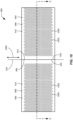
- FIG. 11 is a cross-sectional view of the valve cage 900 of FIGS. 9 and 10 taken along section C-C of FIG. 10 .
- the valve cage 900 of FIGS. 9-11 is a circumferentially-sectioned valve cage having an example circumference 902 formed by a plurality of example cage sections 904 that are removably coupled to one another via example interlocked tab-and-blank connections 906, as further described below.
- the diameter of the valve cage 900 of FIGS. 9-11 may exceed eighteen inches (45,7 cm).
- Each cage section 904 of the valve cage 900 of FIGS. 9-11 is fabricated using an additive manufacturing process, with each resultant cage section 904 being integrally formed as a single-piece structure having the features described herein.
- respective ones of the cage sections 904 of the valve cage 900 of FIGS. 9-11 are fabricated within a common build envelope and/or on a common build platform of a 3D-printer system during a single build performed using an additive manufacturing process.
- each of the cage sections 904 is fabricated such that first ends of the cage sections 904 are aligned with one another within the build envelope and/or on the build platform, second ends of the cage sections 904 are aligned with one another within the build envelope and/or on the build platform, and curvatures of the cage sections 904 extending between the first and second ends of the cage sections 904 are commonly oriented within the build envelope and/or on the build platform.
- one or more of the cage sections 904 of the valve cage 900 of FIGS. 9-11 may alternatively be fabricated using one or more casting, molding, milling, forging and/or drilling processes, with each resultant cage section 904 being integrally formed as a single-piece structure having the features described herein.
- each cage section 904 includes a plurality of example openings 1002 (e.g., through-holes) formed in and extending through an example sidewall 908 of the cage section 904.
- the openings 1002 of each sidewall 908 are configured to enable fluid to pass through the sidewall 908 (e.g., from an outer surface of the sidewall 908 to an inner surface of the sidewall 908).
- the openings 1002 can be formed and/or configured as passages of any size, shape, geometry and/or pattern that enable fluid to pass through the sidewall 908. In the illustrated example of FIGS.
- the sidewalls 908 and/or, more generally, the cage sections 904 of the valve cage 900 define a cylindrical shape having an example central axis 910 and a circular cross-section perpendicular to the central axis 910.
- the sidewalls 908 and/or, more generally, the cage sections 904 of the valve cage 900 may alternatively define a cylindrical shape having an oval or elliptical cross-section perpendicular to the central axis 910.
- the valve cage 900 of FIGS. 9-11 further includes a plurality of example joints 912.
- the joints 912 correspond in number to the cage sections 904, and are spaced apart from one another about the circumference 902 of the valve cage 900 at locations defined by neighboring ones of the cage sections 904.
- the joints 912 of the valve cage 900 extend along an example axial direction 1004 defined by and/or parallel to the central axis 910 of the valve cage 900.
- the joints 912 of the valve cage 900 may alternatively extend in a direction that lies at a non-parallel angle relative to the central axis 910 of the valve cage 900.
- the cage sections 904 of the valve cage 900 include a first example cage section 914, a second example cage section 916, and a third example cage section 918.
- the interlocked tab-and-blank connections 906 of the valve cage 900 include a first example interlocked tab-and-blank connection 920, a second example interlocked tab-and-blank connection 922, and a third example interlocked tab-and-blank connection 924.
- the joints 912 of the valve cage 900 include a first example joint 926, a second example joint 928, and a third example joint 930.
- the first cage section 914 is removably coupled to the second cage section 916 at the first j oint 926 via the first interlocked tab-and-blank connection 920, and is further removably coupled to the third cage section 918 at the third joint 930 via the third interlocked tab-and-blank connection 924.
- the second cage section 916 is removably coupled to the third cage section 918 at the second joint 928 via the second interlocked tab-and-blank connection 922, and is further removably coupled to the first cage section 914 at the first joint 926 via the first interlocked tab-and-blank connection 920.
- the third cage section 918 is removably coupled to the first cage section 914 at the third joint 930 via the third interlocked tab-and-blank connection 924, and is further removably coupled to the second cage section 916 at the second joint 928 via the second interlocked tab-and-blank connection 922.
- Each of the first, second and third cage sections 914, 916, 918 of the valve cage 900 of FIGS. 9-11 has an arc length (e.g., measured along an outer surface of the sidewall 908) equal to approximately one-third of the circumference 902 of the valve cage 900.
- the first, second and third cage sections 914, 916, 918 of the valve cage 900 are uniformly distributed (e.g., equally spaced) about the circumference 902 of the valve cage 900 relative to the central axis 910 of the valve cage 900.
- the first, second and third joints 926, 928, 930 of the valve cage 900 are also uniformly distributed (e.g., equally spaced) about the circumference 902 of the valve cage 900 relative to the central axis 910 of the valve cage 900.
- the valve cage 900 includes three (3) uniformly-distributed cage sections 904 and three uniformly-distributed (3) joints 912, with each of the three (3) cage sections 904 having an arc length equal to approximately one-third of the circumference 902 of the valve cage 900.
- valve cage 900 of FIGS. 9-11 may include a different number of cage sections 904 and a different corresponding number of joints 912 relative to the number of cage sections 904 and joints 912 shown in FIGS. 9-11 .
- the valve cage 900 of FIGS. 9-11 can alternatively be configured to include only two (2) uniformly-distributed cage sections 904 and only two (2) uniformly-distributed joints 912, with each of the two (2) cage sections 904 having an arc length equal to approximately one-half of the circumference 902 of the valve cage 900.
- 9-11 can alternatively be configured to include four (4) uniformly-distributed cage sections 904 and four (4) uniformly-distributed joints 912, with each of the four (4) cage sections 904 having an arc length equal to approximately one-fourth of the circumference 902 of the valve cage 900.
- the valve cage 900 may include cage sections 904 that are not uniformly distributed, and/or that have differing arc lengths.
- the valve cage 900 of FIGS. 9-11 can alternatively be configured to include two (2) non-uniformly-distributed cage sections 904 and two (2) non-uniformly-distributed joints 912, with a first one of the two (2) cage sections 904 having an arc length equal to approximately one-third of the circumference 902 of the valve cage 900, and a second one of the two (2) cage sections 904 having an arc length equal to approximately two-thirds of the circumference 902 of the valve cage 900.
- 9-11 can alternatively be configured to include three (3) non-uniformly-distributed cage sections 904 and three (3) non-uniformly-distributed joints 912, with a first one of the three (3) cage sections 904 having an arc length equal to approximately one-fourth of the circumference 902 of the valve cage 900, a second one of the three (3) cage sections 904 having an arc length equal to approximately one-fourth of the circumference 902 of the valve cage 900, and a third one of the three (3) cage sections 904 having an arc length equal to approximately one-half of the circumference 902 of the valve cage 900.
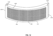
- FIG. 12 is an isolated perspective view of the first cage section 914 of the valve cage 900 of FIGS. 9-11 .
- the second cage section 916 and the third cage section 918 of the valve cage 900 of FIGS. 9-11 are structured and/or configured in a manner that is substantially identical to that of the first cage section 914 shown and described in connection with FIG. 12 .
- the first cage section 914 includes a first example end 1202 and a second example end 1204 located opposite the first end 1202.
- An example tab 1206 is formed and/or located at the first end 1202 of the first cage section 914 such that the tab 1206 extends circumferentially away from the first end 1202 of the first cage section 914.
- An example blank 1208 is formed and/or located at the second end 1204 of the first cage section 914 such that the blank 1208 is recessed circumferentially into the second end 1204 of the first cage section 914. As shown in FIG. 12 , the tab 1206 and the blank 1208 respectively extend along the substantial entirety of the axial dimension of the first cage section 914. In other examples, the tab 1206 and/or the blank 1208 may alternatively extend along only a portion of the axial dimension of the first cage section 914.
- the first cage section 914 of the valve cage 900 is structured and/or configured such that the shape and/or profile of the blank 1208 of the first cage section 914 is complementary to (e.g., is a negative of) the shape and/or profile of the tab 1206 of the first cage section 914.
- the second cage section 916 and the third cage section 918 are structured and/or configured in a substantially identical manner, thereby enabling the tab 1206 of the first cage section 914 shown in FIG.
- the tab 1206 of the first cage section 914 shown in FIG. 12 is interlocked with (e.g., axially disposed in and transversely locked relative to) the blank 1208 of the second cage section 916 of the valve cage 900 (e.g., as shown in FIGS. 9-11 ), the tab 1206 of the first cage section 914 and the blank 1208 of the second cage section 916 collectively form the first interlocked tab-and-blank connection 920.
- the first interlocked tab-and-blank connection 920 removably couples the first cage section 914 to the second cage section 916.
- the tab 1206 of the second cage section 916 of the valve cage 900 When the tab 1206 of the second cage section 916 of the valve cage 900 is interlocked with (e.g., axially disposed in and transversely locked relative to) the blank 1208 of the third cage section 918 of the valve cage 900, the tab 1206 of the second cage section 916 and the blank 1208 of the third cage section 918 collectively form the second interlocked tab-and-blank connection 922.
- the second interlocked tab-and-blank connection 922 removably couples the second cage section 916 to the third cage section 918.
- the tab 1206 of the third cage section 918 of the valve cage 900 When the tab 1206 of the third cage section 918 of the valve cage 900 is interlocked with (e.g., axially disposed in and transversely locked relative to) the blank 1208 of the first cage section 914 shown in FIG. 12 , the tab 1206 of the third cage section 918 and the blank 1208 of the first cage section 914 collectively form the third interlocked tab-and-blank connection 924.
- the third interlocked tab-and-blank connection 924 removably couples the third cage section 918 to the first cage section 914.
- FIG. 13 is a plan view of a fourth example valve cage 1300.
- FIG. 14 is a side view of the valve cage 1300 of FIG. 13 .
- FIG. 15 is a cross-sectional view of the valve cage 1300 of FIGS. 13 and 14 taken along section D-D of FIG. 14 .
- the valve cage 1300 of FIGS. 13-15 is a circumferentially-sectioned valve cage having an example circumference 1302 formed by a plurality of example cage sections 1304 that are removably coupled to one another via example frictional tongue-and-groove connections 1306, as further described below.
- the diameter of the valve cage 1300 of FIGS. 13-15 may exceed eighteen inches (45,7 cm).
- Each cage section 1304 of the valve cage 1300 of FIGS. 13-15 is fabricated using an additive manufacturing process, with each resultant cage section 1304 being integrally formed as a single-piece structure having the features described herein.
- respective ones of the cage sections 1304 of the valve cage 1300 of FIGS. 13-15 are fabricated within a common build envelope and/or on a common build platform of a 3D-printer system during a single build performed using an additive manufacturing process.
- each of the cage sections 1304 is fabricated such that first ends of the cage sections 1304 are aligned with one another within the build envelope and/or on the build platform, second ends of the cage sections 1304 are aligned with one another within the build envelope and/or on the build platform, and curvatures of the cage sections 1304 extending between the first and second ends of the cage sections 1304 are commonly oriented within the build envelope and/or on the build platform.
- one or more of the cage sections 1304 of the valve cage 1300 of FIGS. 13-15 may alternatively be fabricated using one or more casting, molding, milling, forging and/or drilling processes, with each resultant cage section 1304 being integrally formed as a single-piece structure having the features described herein.
- each cage section 1304 includes a plurality of example openings 1402 (e.g., through-holes) formed in and extending through an example sidewall 1308 of the cage section 1304.
- the openings 1402 of each sidewall 1308 are configured to enable fluid to pass through the sidewall 1308 (e.g., from an outer surface of the sidewall 1308 to an inner surface of the sidewall 1308).
- the openings 1402 can be formed and/or configured as passages of any size, shape, geometry and/or pattern that enable fluid to pass through the sidewall 1308. In the illustrated example of FIGS.
- the sidewalls 1308 and/or, more generally, the cage sections 1304 of the valve cage 1300 define a cylindrical shape having an example central axis 1310 and a circular cross-section perpendicular to the central axis 1310.
- the sidewalls 1308 and/or, more generally, the cage sections 1304 of the valve cage 1300 may alternatively define a cylindrical shape having an oval or elliptical cross-section perpendicular to the central axis 1310.
- the valve cage 1300 of FIGS. 13-15 further includes a plurality of example joints 1312.
- the joints 1312 correspond in number to the cage sections 1304, and are spaced apart from one another about the circumference 1302 of the valve cage 1300 at locations defined by neighboring ones of the cage sections 1304.
- the joints 1312 of the valve cage 1300 extend along an example axial direction 1404 defined by and/or parallel to the central axis 1310 of the valve cage 1300.
- the joints 1312 of the valve cage 1300 may alternatively extend in a direction that lies at a non-parallel angle relative to the central axis 1310 of the valve cage 1300.
- the cage sections 1304 of the valve cage 1300 include a first example cage section 1314, a second example cage section 1316, and a third example cage section 1318.
- the frictional tongue-and-groove connections 1306 of the valve cage 1300 include a first example frictional tongue-and-groove connection 1320, a second example frictional tongue-and-groove connection 1322, and a third example frictional tongue-and-groove connection 1324.
- the joints 1312 of the valve cage 1300 include a first example joint 1326, a second example joint 1328, and a third example joint 1330.
- the first cage section 1314 is removably coupled to the second cage section 1316 at the first joint 1326 via the first frictional tongue-and-groove connection 1320, and is further removably coupled to the third cage section 1318 at the third joint 1330 via the third frictional tongue-and-groove connection 1324.
- the second cage section 1316 is removably coupled to the third cage section 1318 at the second joint 1328 via the second frictional tongue-and-groove connection 1322, and is further removably coupled to the first cage section 1314 at the first joint 1326 via the first frictional tongue-and-groove connection 1320.
- the third cage section 1318 is removably coupled to the first cage section 1314 at the third joint 1330 via the third frictional tongue-and-groove connection 1324, and is further removably coupled to the second cage section 1316 at the second joint 1328 via the second frictional tongue-and-groove connection 1322.
- Each of the first, second and third cage sections 1314, 1316, 1318 of the valve cage 1300 of FIGS. 13-15 has an arc length (e.g., measured along an outer surface of the sidewall 1308) equal to approximately one-third of the circumference 1302 of the valve cage 1300.
- the first, second and third cage sections 1314, 1316, 1318 of the valve cage 1300 are uniformly distributed (e.g., equally spaced) about the circumference 1302 of the valve cage 1300 relative to the central axis 1310 of the valve cage 1300.
- the first, second and third joints 1326, 1328, 1330 of the valve cage 1300 are also uniformly distributed (e.g., equally spaced) about the circumference 1302 of the valve cage 1300 relative to the central axis 1310 of the valve cage 1300.
- the valve cage 1300 includes three (3) uniformly-distributed cage sections 1304 and three uniformly-distributed (3) joints 1312, with each of the three (3) cage sections 1304 having an arc length equal to approximately one-third of the circumference 1302 of the valve cage 1300.
- valve cage 1300 of FIGS. 13-15 may include a different number of cage sections 1304 and a different corresponding number of joints 1312 relative to the number of cage sections 1304 and joints 1312 shown in FIGS. 13-15 .
- the valve cage 1300 of FIGS. 13-15 can alternatively be configured to include only two (2) uniformly-distributed cage sections 1304 and only two (2) uniformly-distributed joints 1312, with each of the two (2) cage sections 1304 having an arc length equal to approximately one-half of the circumference 1302 of the valve cage 1300.
- 13-15 can alternatively be configured to include four (4) uniformly-distributed cage sections 1304 and four (4) uniformly-distributed joints 1312, with each of the four (4) cage sections 1304 having an arc length equal to approximately one-fourth of the circumference 1302 of the valve cage 1300.
- the valve cage 1300 may include cage sections 1304 that are not uniformly distributed, and/or that have differing arc lengths.
- the valve cage 1300 of FIGS. 13-15 can alternatively be configured to include two (2) non-uniformly-distributed cage sections 1304 and two (2) non-uniformly-distributed joints 1312, with a first one of the two (2) cage sections 1304 having an arc length equal to approximately one-third of the circumference 1302 of the valve cage 1300, and a second one of the two (2) cage sections 1304 having an arc length equal to approximately two-thirds of the circumference 1302 of the valve cage 1300.
- 13-15 can alternatively be configured to include three (3) non-uniformly-distributed cage sections 1304 and three (3) non-uniformly-distributed joints 1312, with a first one of the three (3) cage sections 1304 having an arc length equal to approximately one-fourth of the circumference 1302 of the valve cage 1300, a second one of the three (3) cage sections 1304 having an arc length equal to approximately one-fourth of the circumference 1302 of the valve cage 1300, and a third one of the three (3) cage sections 1304 having an arc length equal to approximately one-half of the circumference 1302 of the valve cage 1300.
- FIG. 16 is an isolated perspective view of the first cage section 1314 of the valve cage 1300 of FIGS. 13-15 .
- the second cage section 1316 and the third cage section 1318 of the valve cage 1300 of FIGS. 13-15 are structured and/or configured in a manner that is substantially identical to that of the first cage section 1314 shown and described in connection with FIG. 16 .
- the first cage section 1314 includes a first example end 1602 and a second example end 1604 located opposite the first end 1602.
- Example tongues 1606 are formed and/or located at the first end 1602 of the first cage section 1314 such that respective ones of the tongues 1606 are radially spaced apart from one another and extend circumferentially away from the first end 1602 of the first cage section 1314.
- Example grooves 1608 are formed and/or located at the second end 1604 of the first cage section 1314 such that respective ones of the grooves 1608 are radially spaced apart from one another and recessed circumferentially into the second end 1604 of the first cage section 1314. As shown in FIG. 16 , the tongues 1606 and the grooves 1608 respectively extend along the substantial entirety of the axial dimension of the first cage section 1314. In other examples, the tongues 1606 and/or the grooves 1608 may alternatively extend along only a portion of the axial dimension of the first cage section 1314.
- the first cage section 1314 of the valve cage 1300 is structured and/or configured such that the respective shapes and/or profiles of the grooves 1608 of the first cage section 1314 are complementary to (e.g., are negatives of) the respective shapes and/or profiles of the tongues 1606 of the first cage section 1314.
- the second cage section 1316 and the third cage section 1318 are structured and/or configured in a substantially identical manner, thereby enabling respective ones of the tongues 1606 of the first cage section 1314 shown in FIG.
- the respective ones of the tongues 1606 of the first cage section 1314 shown in FIG. 16 are circumferentially disposed in and frictionally retained by the corresponding respective ones of the grooves 1608 of the second cage section 1316 of the valve cage 1300 (e.g., as shown in FIGS. 13-15 ), the respective ones of the tongues 1606 of the first cage section 1314 and the corresponding respective ones of the grooves 1608 of the second cage section 1316 collectively form the first frictional tongue-and-groove connection 1320.
- the first frictional tongue-and-groove connection 1320 removably couples the first cage section 1314 to the second cage section 1316.
- the respective ones of the tongues 1606 of the second cage section 1316 of the valve cage 1300 are circumferentially disposed in and frictionally retained by the corresponding respective ones of the grooves 1608 of the third cage section 1318 of the valve cage 1300, the respective ones of the tongues 1606 of the second cage section 1316 and the corresponding respective ones of the grooves 1608 of the third cage section 1318 collectively form the second frictional tongue-and-groove connection 1322.
- the second frictional tongue-and-groove connection 1322 removably couples the second cage section 1316 to the third cage section 1318.
- the respective ones of the tongues 1606 of the third cage section 1318 of the valve cage 1300 are circumferentially disposed in and frictionally retained by the corresponding respective ones of the grooves 1608 of the first cage section 1314 shown in FIG. 16 , the respective ones of the tongues 1606 of the third cage section 1318 and the corresponding respective ones of the grooves 1608 of the first cage section 1314 collectively form the third frictional tongue-and-groove connection 1324.
- the third frictional tongue-and-groove connection 1324 removably couples the third cage section 1318 to the first cage section 1314.
- FIG. 17 is a cross-sectional view of an example valve 1700 including an example circumferentially-sectioned valve cage 1702.
- the circumferentially-sectioned valve cage 1702 of the valve 1700 of FIG. 17 can be implemented by the first example valve cage 100 of FIGS. 1-4 described above, by the second example valve cage 500 of FIGS. 5-8 described above, by the third example valve cage 900 of FIGS. 9-12 described above, or by the fourth example valve cage 1300 of FIGS. 13-16 described above.
- the valve 1700 further includes (e.g., in addition to the circumferentially-sectioned valve cage 1702) an example valve body 1704, an example seat ring 1706, an example plug 1708, an example stem 1710, and an example bonnet 1712.
- the valve body 1704 includes an example inlet 1714, an example cavity 1716, and an example outlet 1718.
- the circumferentially-sectioned valve cage 1702, the seat ring 1706, and the plug 1708 are located within the cavity 1716 of the valve body 1704. A fluid flowing through the valve body 1704 and/or, more generally, through the valve 1700 of FIG.
- the seat ring 1706 of the valve 1700 is configured to mate with the plug 1708 of the valve 1700 when the plug 1708 and/or, more generally, the valve 1700, is in a closed position. As shown in FIG. 17 the plug 1708 and/or, more generally, the valve 1700, is in an open position.
- the stem 1710 of the valve 1700 is coupled to the plug 1708 by, for example, a threaded connection formed by a threaded end of the stem 1710 and a threaded bore of the plug 1708.
- the plug 1708 and the stem 1710 are movable and/or slidable within the circumferentially-sectioned valve cage 1702 and relative to the seat ring 1706 of the valve 1700 along an example longitudinal axis 1726 defined by the stem 1710.
- the plug 1708 moves and/or slides downward from its current position shown in FIG. 17 past the openings 1720 formed in the sidewall 1722 of the circumferentially-sectioned valve cage 1702, fluid passing through the valve 1700 is restricted and/or blocked.
- the plug 1708 is configured to mate with the seat ring 1706 to fully close off the fluid pathway 1724 shown in FIG. 17 .
- the bonnet 1712 of the valve 1700 is removably coupled to the valve body 1704 via a plurality of example nuts 1728 and example bolts and/or threaded studs 1730.
- the bonnet 1712 confines the circumferentially-sectioned valve cage 1702, the seat ring 1706, and the plug 1708 within the cavity 1716 of the valve body 1704.
- the stem 1710 passes through an example opening 1732 of the bonnet 1712, and an example portion 1734 of the stem 1710 protrudes externally from the opening 1732 of the bonnet 1712.
- the stem 1710 is movable and/or slidable along the longitudinal axis 1726 relative to the seat ring 1706 of the valve 1700.
- example circumferentially-sectioned valve cages have been disclosed.
- the example circumferentially-sectioned valve cages disclosed herein include a plurality of cage sections that are removably couplable to one another to form a circumference of the valve cage.
- the example circumferentially-sectioned valve cages disclosed herein include joints corresponding in number to the cage sections, with the joints being spaced apart from one another about the circumference of the valve cage, and respective ones of the joints being defined by neighboring ones of the cage sections.
- the example circumferentially-sectioned valve cages disclosed herein have a diameter exceeding eighteen inches (45,7 cm).
- an apparatus comprising a plurality of cage sections collectively configured to be removably coupled together to form a valve cage having a circumference and a plurality of joints.
- the joints correspond in number to the cage sections and are spaced apart from one another about the circumference.
- respective ones of the joints are defined by neighboring ones of the cage sections.
- the joints extend in an axial direction defined by a central axis of the valve cage.
- respective ones of the cage sections have corresponding arc lengths. In some disclosed examples, respective ones of the corresponding arc lengths are equal to one another.
- the cage sections include a first cage section, a second cage section, and a third cage section.
- the first cage section is configured to be removably coupled to the second and third cage sections.
- the second cage section is configured to be removably coupled to the first and third cage sections.
- the third cage section is configured to be removably coupled to the first and second cage sections.
- the cage sections include a first cage section and a second cage section.
- the first cage section including a first arm extending circumferentially away from an end of the first cage section.
- the first arm has a first axially-oriented opening.
- the second cage section includes a second arm extending circumferentially away from an end of the second cage section.
- the second arm has a second axially-oriented opening.
- the second arm is configured to be interleaved with the first arm.
- the second axially-oriented opening is configured to align with the first axially-oriented opening.
- the aligned first and second axially-oriented openings are configured to receive a pin.
- the pin is configured to removably couple the first cage section to the second cage section.
- the cage sections include a first cage section and a second cage section.
- the first cage section includes a first sidewall and a first flange extending outwardly from the first sidewall.
- the first flange has a first transversely-oriented opening.
- the second cage section includes a second sidewall and a second flange extending outwardly from the second sidewall.
- the second flange has a second transversely-oriented opening configured to align with the first transversely-oriented opening.
- the aligned first and second transversely-oriented openings are configured to receive a bolt.
- the bolt is configured to removably couple the first cage section to the second cage section.
- the cage sections include a first cage section and a second cage section.
- the first cage section includes a tab extending circumferentially away from an end of the first cage section.
- the second cage section includes a blank recessed circumferentially into an end of the second cage section.
- the blank is configured to axially receive the tab to form an interlocked tab-and-blank connection.
- the interlocked tab-and-blank connection is configured to removably couple the first cage section to the second cage section.
- the cage sections include a first cage section and a second cage section.
- the first cage section includes a tongue extending circumferentially away from an end of the first cage section.
- the second cage section includes a groove recessed circumferentially into an end of the second cage section.
- the groove is configured to receive the tongue to form a frictional tongue-and-groove connection.
- the frictional tongue-and-groove connection is configured to removably couple the first cage section to the second cage section.
- a valve cage in some examples, the valve cage comprises a plurality of cage sections removably coupled together to form a circumference of the valve cage. In some disclosed examples, the valve cage comprises a plurality of joints. In some disclosed examples, the joints correspond in number to the cage sections and are spaced apart from one another about the circumference. In some disclosed examples, respective ones of the joints are defined by neighboring ones of the cage sections.
- the joints extend in an axial direction defined by a central axis of the valve cage.
- respective ones of the cage sections have corresponding arc lengths. In some disclosed examples, respective ones of the corresponding arc lengths are equal to one another.
- the valve cage further comprises a pin.
- the cage sections include a first cage section and a second cage section.
- the first cage section includes a first arm extending circumferentially away from an end of the first cage section.
- the first arm has a first axially-oriented opening.
- the second cage section includes a second arm extending circumferentially away from an end of the second cage section.
- the second arm has a second axially-oriented opening.
- the second arm is interleaved with the first arm.
- the second axially-oriented opening is aligned with the first axially-oriented opening.
- the pin is disposed in the first and second axially-oriented openings. In some disclosed examples, the pin removably couples the first cage section to the second cage section.
- the valve cage further comprises a bolt.
- the cage sections include a first cage section and a second cage section.
- the first cage section includes a first sidewall and a first flange extending outwardly from the first sidewall.
- the first flange has a first transversely-oriented opening.
- the second cage section includes a second sidewall and a second flange extending outwardly from the second sidewall.
- the second flange has a second transversely-oriented opening aligned with the first transversely-oriented opening.
- the bolt is disposed in the first and second transversely-oriented openings. In some disclosed examples, the bolt removably couples the first cage section to the second cage section.
- the valve cage further comprises an interlocked tab-and-blank connection.
- the cage sections include a first cage section and a second cage section.
- the first cage section includes a tab extending circumferentially away from an end of the first cage section.
- the second cage section includes a blank recessed circumferentially into an end of the second cage section.
- the blank axially receives the tab to form the interlocked tab-and-blank connection.
- the interlocked tab-and-blank connection removably couples the first cage section to the second cage section.
- the valve cage further comprises a frictional tongue-and-groove connection.
- the cage sections include a first cage section and a second cage section.
- the first cage section includes a tongue extending circumferentially away from an end of the first cage section.
- the second cage section includes a groove recessed circumferentially into an end of the second cage section.
- the groove receives the tongue to form the frictional tongue-and-groove connection.
- the frictional tongue-and-groove connection removably couples the first cage section to the second cage section.
- a valve in some examples, the valve comprises a valve body and a valve cage located within the valve body.
- the valve cage includes a plurality of cage sections removably coupled together to form a circumference of the valve cage.
- the valve cage further includes a plurality of joints.
- the joints correspond in number to the cage sections and are spaced apart from one another about the circumference.
- respective ones of the joints are defined by neighboring ones of the cage sections.
- the valve cage further includes a pin.
- the cage sections include a first cage section and a second cage section.
- the first cage section includes a first arm extending circumferentially away from an end of the first cage section.
- the first arm has a first axially-oriented opening.
- the second cage section includes a second arm extending circumferentially away from an end of the second cage section.
- the second arm has a second axially-oriented opening.
- the second arm is interleaved with the first arm.
- the second axially-oriented opening is aligned with the first axially-oriented opening.
- the pin is disposed in the first and second axially-oriented openings. In some disclosed examples, the pin removably couples the first cage section to the second cage section.
- the valve cage further includes a bolt.
- the cage sections include a first cage section and a second cage section.
- the first cage section includes a first sidewall and a first flange extending outwardly from the first sidewall.
- the first flange has a first transversely-oriented opening.
- the second cage section includes a second sidewall and a second flange extending outwardly from the second sidewall.
- the second flange has a second transversely-oriented opening aligned with the first transversely-oriented opening.
- the bolt is disposed in the first and second transversely-oriented openings. In some disclosed examples, the bolt removably couples the first cage section to the second cage section.
- the valve cage further includes an interlocked tab-and-blank connection.
- the cage sections include a first cage section and a second cage section.
- the first cage section includes a tab extending circumferentially away from an end of the first cage section.
- the second cage section includes a blank recessed circumferentially into an end of the second cage section.
- the blank axially receives the tab to form the interlocked tab-and-blank connection.
- the interlocked tab-and-blank connection removably couples the first cage section to the second cage section.
- the valve cage further includes a frictional tongue-and-groove connection.
- the cage sections include a first cage section and a second cage section.
- the first cage section includes a tongue extending circumferentially away from an end of the first cage section.
- the second cage section includes a groove recessed circumferentially into an end of the second cage section.
- the groove receives the tongue to form the frictional tongue-and-groove connection.
- the frictional tongue-and-groove connection removably couples the first cage section to the second cage section.
Landscapes
- Engineering & Computer Science (AREA)
- General Engineering & Computer Science (AREA)
- Mechanical Engineering (AREA)
- Valve Housings (AREA)
Description
- This disclosure relates generally to valve cages and, more particularly, to circumferentially-sectioned valve cages.
- Valves commonly include a valve body defining a fluid pathway having an inlet and outlet. A plug located within the valve body is movable relative to a seat ring located within the valve body to control the flow of a fluid through the valve body and/or along the fluid pathway. In some known valves, the flow of the fluid through the valve body and/or along the fluid pathway is further controlled and/or impacted via a cage located within the valve body. The cage typically has a cylindrical, single-piece (e.g., joint-free) shape and/or configuration, with the cage being arranged within the valve body such that a sidewall of the cage circumscribes the plug. The sidewall of the cage includes a plurality of fluid passages and/or openings (e.g., through-holes) arranged in a spaced relationship about the sidewall and/or around the circumference of the cage.
- Fluid flowing through the valve body and/or along the fluid pathway of the valve passes from the inlet of the valve body, through the seat ring, through one or more of the openings of the sidewall of the cage, and toward the outlet of the valve body. The arrangement and/or orientation of the openings about the sidewall and/or around the circumference of the cage impacts the flow characteristics of the fluid passing through the valve body and/or along the fluid pathway, including the rate at which the fluid passes through the valve body and/or along the fluid pathway.
-
US 4,356,843 A shows a lamellate fluid resistance device which may be part of fluid systems to dissipate moderate pressure differentials. Ring-shaped plates are removably stacked one over the other to form a circumference. A ring portion of each plate is removed to provide a wedge-shaped opening in the circumference. Each successive plate is rotatively displaced to the adjacent one displacing also the wedge-shaped openings relative to each other. - Example circumferentially-sectioned valve cages are shown. In some examples, an apparatus is shown. In some examples, the apparatus comprises a plurality of cage sections collectively configured to be removably coupled together to form a valve cage having a circumference and a plurality of joints. In some examples, the joints correspond in number to the cage sections and are spaced apart from one another about the circumference. In some examples, respective ones of the joints are defined by neighboring ones of the cage sections.
- A valve cage with the features of claim 1 is provided.
- In some examples, a valve is disclosed. In some disclosed examples, the valve comprises a valve body and a valve cage located within the valve body.
-
-
FIG. 1 is a plan view of a first example valve cage. -
FIG. 2 is a side view of the valve cage ofFIG. 1 . -
FIG. 3 is a cross-sectional view of the valve cage ofFIGS. 1 and2 taken along section A-A ofFIG. 2 . -
FIG. 4 is an isolated perspective view of one of the cage sections of the valve cage ofFIGS. 1-3 . -
FIG. 5 is a plan view of a second example valve cage. -
FIG. 6 is a side view of the valve cage ofFIG. 5 . -
FIG. 7 is a cross-sectional view of the valve cage ofFIGS. 5 and6 taken along section B-B ofFIG. 6 . -
FIG. 8 is an isolated perspective view of one of the cage sections of the valve cage ofFIGS. 5-7 . -
FIG. 9 is a plan view of a third example valve cage. -
FIG. 10 is a side view of the valve cage ofFIG. 9 . -
FIG. 11 is a cross-sectional view of the valve cage ofFIGS. 9 and10 taken along section C-C ofFIG. 10 . -
FIG. 12 is an isolated perspective view of one of the cage sections of the valve cage ofFIGS. 9-11 . -
FIG. 13 is a plan view of a fourth example valve cage. -
FIG. 14 is a side view of the valve cage ofFIG. 13 . -
FIG. 15 is a cross-sectional view of the valve cage ofFIGS. 13 and14 taken along section D-D ofFIG. 14 . -
FIG. 16 is an isolated perspective view of one of the cage sections of the valve cage ofFIGS. 13-15 . -
FIG. 17 is a cross-sectional view of an example valve including an example circumferentially-sectioned valve cage. - Certain examples are shown in the above-identified figures and described in detail below. In describing these examples, identical reference numbers are used to identify the same or similar elements. The figures are not necessarily to scale and certain features and certain views of the figures may be shown exaggerated in scale or in schematic for clarity and/or conciseness.
- Descriptors "first," "second," "third," etc. are used herein when identifying multiple elements or components which may be referred to separately. Unless otherwise specified or understood based on their context of use, such descriptors are not intended to impute any meaning of priority or ordering in time but merely as labels for referring to multiple elements or components separately for ease of understanding the disclosed examples. In some examples, the descriptor "first" may be used to refer to an element in the detailed description, while the same element may be referred to in a claim with a different descriptor such as "second" or "third." In such instances, it should be understood that such descriptors are used merely for ease of referencing multiple elements or components.
- As used herein in reference to a component (e.g., a valve cage, etc.), the term "single-piece" refers to a unitary, one-piece component that is free of joints held together via welding or other mechanical coupling, joining and/or fastening components. As used herein in reference to a first component (e.g., a first cage section of a valve cage) coupled to a second component (e.g., a second cage section of the valve cage), the term "removably coupled" means the first component is coupled, joined, connected and/or fastened to the second component via one or more coupling, joining, connecting and/or fastening component(s) in a non-permanent manner that enables the first component to subsequently be uncoupled, unjoined, unconnected and/or unfastened from the second component without damaging and/or destroying the coupling, joining, connecting and/or fastening component(s). As used herein, the term "additive manufacturing" refers generally to a process by which three-dimensional design data (e.g., a computer-aided design (CAD) file) is used in conjunction with a controllable laser to fabricate an object by depositing successive layers of material on top of one another. For example, rather than milling and/or machining an object from a solid block of material, additive manufacturing fabricates the object layer by layer using one or more material(s) in the form of a fine powder (e.g., a metallic powder, a plastic powder, a composite powder, etc.) capable of being solidified by application of the laser thereto.
- Known valve cages typically have a cylindrical, single-piece (e.g., joint-free) shape that is sized and/or configured to facilitate centrally locating a cylindrical valve plug within the valve cage, such that a sidewall of the valve cage circumscribes the valve plug. The sidewall of the valve cage includes a plurality of fluid passages and/or openings (e.g., through-holes) arranged in a spaced relationship about the sidewall and/or around the circumference of the cage.
- The known single-piece valve cages described above have traditionally been fabricated using a variety of casting, molding, milling, forging and/or drilling processes and/or techniques. More recently, consideration has been given to fabricating single-piece valve cages via additive manufacturing processes and/or techniques that have commercially evolved. Regardless of the chosen process, challenges and/or constraints often arise when the single-piece valve cage for which fabrication is desired has a relatively large size (e.g., a diameter exceeding 45,7 centimetre (18 inches)). For example, conventional tooling and/or molds become more complex and/or more costly as the desired size of the single-piece valve cage increases. As another example, most commercially available 3D-printer systems that facilitate additive manufacturing have build envelopes and/or build platforms that prevent and/or prohibit the ability to fabricate a relatively large single-piece valve cage.
- Unlike the known single-piece valve cages described above, example valve cages disclosed herein are circumferentially sectioned. More specifically, example valve cages disclosed herein include a plurality of cage sections that are removably couplable to one another to form a circumference of the valve cage. When assembled (e.g., when the cage sections are removably coupled to one another), the example circumferentially-sectioned valve cages disclosed herein include joints corresponding in number to the cage sections, with the joints being spaced apart from one another about the circumference of the valve cage, and respective ones of the joints being defined by neighboring ones of the cage sections. In some examples, the example circumferentially-sectioned valve cages disclosed herein have a diameter exceeding eighteen inches (45,7 cm). By fabricating the example circumferentially-sectioned valve cages disclosed herein as a plurality of removably couplable cage sections, as opposed to a single-piece valve cage, the above-described challenges and/or constraints that often arise when fabricating a single-piece valve cage having a relatively large size are advantageously eliminated.
-
FIG. 1 is a plan view of a firstexample valve cage 100.FIG. 2 is a side view of thevalve cage 100 ofFIG. 1 .FIG. 3 is a cross-sectional view of thevalve cage 100 ofFIGS. 1 and2 taken along section A-A ofFIG. 2 . Thevalve cage 100 ofFIGS. 1-3 is a circumferentially-sectioned valve cage having anexample circumference 102 formed by a plurality ofexample cage sections 104 that are removably coupled to one another via example pins 106, as further described below. In some examples, the diameter of thevalve cage 100 ofFIGS. 1-3 may exceed eighteen inches (45,7 cm). - Each
cage section 104 of thevalve cage 100 ofFIGS. 1-3 is fabricated using an additive manufacturing process, with eachresultant cage section 104 being integrally formed as a single-piece structure having the features described herein. In some examples, respective ones of thecage sections 104 of thevalve cage 100 ofFIGS. 1-3 are fabricated within a common build envelope and/or on a common build platform of a 3D-printer system during a single build performed using an additive manufacturing process. In some such examples, each of thecage sections 104 is fabricated such that first ends of thecage sections 104 are aligned with one another within the build envelope and/or on the build platform, second ends of thecage sections 104 are aligned with one another within the build envelope and/or on the build platform, and curvatures of thecage sections 104 extending between the first and second ends of thecage sections 104 are commonly oriented within the build envelope and/or on the build platform. In other examples, one or more of thecage sections 104 of thevalve cage 100 ofFIGS. 1-3 may alternatively be fabricated using one or more casting, molding, milling, forging and/or drilling processes, with eachresultant cage section 104 being integrally formed as a single-piece structure having the features described herein. - As shown in
FIGS. 2 and3 , eachcage section 104 includes a plurality of example openings 202 (e.g., through-holes) formed in and extending through anexample sidewall 108 of thecage section 104. Theopenings 202 of eachsidewall 108 are configured to enable fluid to pass through the sidewall 108 (e.g., from an outer surface of thesidewall 108 to an inner surface of the sidewall 108). Theopenings 202 can be formed and/or configured as passages of any size, shape, geometry and/or pattern that enable fluid to pass through thesidewall 108. In the illustrated example ofFIGS. 1-3 , thesidewalls 108 and/or, more generally, thecage sections 104 of thevalve cage 100 define a cylindrical shape having an examplecentral axis 110 and a circular cross-section perpendicular to thecentral axis 110. In other examples, thesidewalls 108 and/or, more generally, thecage sections 104 of thevalve cage 100 may alternatively define a cylindrical shape having an oval or elliptical cross-section perpendicular to thecentral axis 110. - The
valve cage 100 ofFIGS. 1-3 further includes a plurality of example joints 112. Thejoints 112 correspond in number to thecage sections 104, and are spaced apart from one another about thecircumference 102 of thevalve cage 100 at locations defined by neighboring ones of thecage sections 104. As shown inFIG. 2 , thejoints 112 of thevalve cage 100 extend along an exampleaxial direction 204 defined by and/or parallel to thecentral axis 110 of thevalve cage 100. In other examples, thejoints 112 of thevalve cage 100 may alternatively extend in a direction that lies at a non-parallel angle relative to thecentral axis 110 of thevalve cage 100. - In the illustrated example of
FIGS. 1-3 , thecage sections 104 of thevalve cage 100 include a firstexample cage section 114, a secondexample cage section 116, and a thirdexample cage section 118. Thepins 106 of thevalve cage 100 include afirst example pin 120, asecond example pin 122, and athird example pin 124. Thejoints 112 of thevalve cage 100 include a first example joint 126, a second example joint 128, and a third example joint 130. Thefirst cage section 114 is removably coupled to thesecond cage section 116 at the first joint 126 via thefirst pin 120, and is further removably coupled to thethird cage section 118 at the third joint 130 via thethird pin 124. Thesecond cage section 116 is removably coupled to thethird cage section 118 at the second joint 128 via thesecond pin 122, and is further removably coupled to thefirst cage section 114 at the first joint 126 via thefirst pin 120. Thethird cage section 118 is removably coupled to thefirst cage section 114 at the third joint 130 via thethird pin 124, and is further removably coupled to thesecond cage section 116 at the second joint 128 via thesecond pin 122. - Each of the first, second and
third cage sections valve cage 100 ofFIGS. 1-3 has an arc length (e.g., measured along an outer surface of the sidewall 108) equal to approximately one-third of thecircumference 102 of thevalve cage 100. In the illustrated example ofFIGS. 1-3 , the first, second andthird cage sections valve cage 100 are uniformly distributed (e.g., equally spaced) about thecircumference 102 of thevalve cage 100 relative to thecentral axis 110 of thevalve cage 100. The first, second andthird joints valve cage 100 are also uniformly distributed (e.g., equally spaced) about thecircumference 102 of thevalve cage 100 relative to thecentral axis 110 of thevalve cage 100. Thus, in the illustrated example ofFIGS. 1-3 , thevalve cage 100 includes three (3) uniformly-distributedcage sections 104 and three uniformly-distributed (3) joints 112, with each of the three (3)cage sections 104 having an arc length equal to approximately one-third of thecircumference 102 of thevalve cage 100. - In other examples, the
valve cage 100 ofFIGS. 1-3 may include a different number ofcage sections 104 and a different corresponding number ofjoints 112 relative to the number ofcage sections 104 andjoints 112 shown inFIGS. 1-3 . For example, thevalve cage 100 ofFIGS. 1-3 can alternatively be configured to include only two (2) uniformly-distributedcage sections 104 and only two (2) uniformly-distributedjoints 112, with each of the two (2)cage sections 104 having an arc length equal to approximately one-half of thecircumference 102 of thevalve cage 100. As another example, thevalve cage 100 ofFIGS. 1-3 can alternatively be configured to include four (4) uniformly-distributedcage sections 104 and four (4) uniformly-distributedjoints 112, with each of the four (4)cage sections 104 having an arc length equal to approximately one-fourth of thecircumference 102 of thevalve cage 100. - In still other examples, the
valve cage 100 may includecage sections 104 that are not uniformly distributed, and/or that have differing arc lengths. For example, thevalve cage 100 ofFIGS. 1-3 can alternatively be configured to include two (2) non-uniformly-distributedcage sections 104 and two (2) non-uniformly-distributedjoints 112, with a first one of the two (2)cage sections 104 having an arc length equal to approximately one-third of thecircumference 102 of thevalve cage 100, and a second one of the two (2)cage sections 104 having an arc length equal to approximately two-thirds of thecircumference 102 of thevalve cage 100. As another example, thevalve cage 100 ofFIGS. 1-3 can alternatively be configured to include three (3) non-uniformly-distributedcage sections 104 and three (3) non-uniformly-distributedjoints 112, with a first one of the three (3)cage sections 104 having an arc length equal to approximately one-fourth of thecircumference 102 of thevalve cage 100, a second one of the three (3)cage sections 104 having an arc length equal to approximately one-fourth of thecircumference 102 of thevalve cage 100, and a third one of the three (3)cage sections 104 having an arc length equal to approximately one-half of thecircumference 102 of thevalve cage 100. -
FIG. 4 is an isolated perspective view of thefirst cage section 114 of thevalve cage 100 ofFIGS. 1-3 . Thesecond cage section 116 and thethird cage section 118 of thevalve cage 100 ofFIGS. 1-3 are structured and/or configured in a manner that is substantially identical to that of thefirst cage section 114 shown and described in connection withFIG. 4 . As shown inFIG. 4 , thefirst cage section 114 includes afirst example end 402 and asecond example end 404 located opposite thefirst end 402.First example arms 406 are formed and/or located at thefirst end 402 of thefirst cage section 114 such that thefirst arms 406 extend circumferentially away from thefirst end 402 of thefirst cage section 114. Respective ones of thefirst arms 406 are axially spaced apart from one another (e.g., along theaxial direction 204 ofFIG. 2 ). Each of thefirst arms 406 includes a first example axially-oriented opening 408 (e.g., a bore or through-hole extending along theaxial direction 204 ofFIG. 2 ). Respective ones of thefirst arms 406 are axially aligned with one another (e.g., along theaxial direction 204 ofFIG. 2 ), as are respective ones of the first axially-orientedopenings 408. - As further shown in
FIG. 4 ,second example arms 410 are formed and/or located at thesecond end 404 of thefirst cage section 114 such that thesecond arms 410 extend circumferentially away from thesecond end 404 of thefirst cage section 114. Respective ones of thesecond arms 410 are axially spaced apart from one another (e.g., along theaxial direction 204 ofFIG. 2 ). Each of thesecond arms 410 includes a second example axially-oriented opening 412 (e.g., a bore or through-hole extending along theaxial direction 204 ofFIG. 2 ). Respective ones of thesecond arms 410 are axially aligned with one another (e.g., along theaxial direction 204 ofFIG. 2 ), as are respective ones of the second axially-orientedopenings 412. - The
first cage section 114 of thevalve cage 100 is structured and/or configured such that the respective axial locations of thesecond arms 410 of thefirst cage section 114 are staggered and/or offset relative to the respective axial locations of thefirst arms 406 of thefirst cage section 114. Thesecond cage section 116 and thethird cage section 118 are structured and/or configured in a substantially identical manner, thereby enabling thefirst arms 406 of thefirst cage section 114 shown inFIG. 4 to be interleaved with thesecond arms 410 of thesecond cage section 116 of thevalve cage 100, further enabling thesecond arms 410 of thefirst cage section 114 shown inFIG. 4 to be interleaved with thefirst arms 406 of thethird cage section 118 of thevalve cage 100, and still further enabling thefirst arms 406 of thesecond cage section 116 of thevalve cage 100 to be interleaved with thesecond arms 410 of thethird cage section 118. - When the
first arms 406 of thefirst cage section 114 shown inFIG. 4 are interleaved with thesecond arms 410 of thesecond cage section 116 of the valve cage 100 (e.g., as shown inFIGS. 1-3 ), the first axially-orientedopenings 408 of thefirst arms 406 of thefirst cage section 114 are axially aligned with the second axially-orientedopenings 412 of thesecond arms 410 of thesecond cage section 116. Axial alignment between the first axially-orientedopenings 408 of thefirst arms 406 of thefirst cage section 114 and the second axially-orientedopenings 412 of thesecond arms 410 of thesecond cage section 116 enables thefirst pin 120 to be disposed through and/or within respective ones of the aligned axially-oriented openings. When so disposed, thefirst pin 120 removably couples thefirst cage section 114 to thesecond cage section 116. - When the
first arms 406 of thesecond cage section 116 of thevalve cage 100 are interleaved with thesecond arms 410 of thethird cage section 118 of thevalve cage 100, the first axially-orientedopenings 408 of thefirst arms 406 of thesecond cage section 116 are axially aligned with the second axially-orientedopenings 412 of thesecond arms 410 of thethird cage section 118. Axial alignment between the first axially-orientedopenings 408 of thefirst arms 406 of thesecond cage section 116 and the second axially-orientedopenings 412 of thesecond arms 410 of thethird cage section 118 enables thesecond pin 122 to be disposed through and/or within respective ones of the aligned axially-oriented openings. When so disposed, thesecond pin 122 removably couples thesecond cage section 116 to thethird cage section 118. - When the
first arms 406 of thethird cage section 118 of thevalve cage 100 are interleaved with thesecond arms 410 of thefirst cage section 114 of thevalve cage 100, the first axially-orientedopenings 408 of thefirst arms 406 of thethird cage section 118 are axially aligned with the second axially-orientedopenings 412 of thesecond arms 410 of thefirst cage section 114. Axial alignment between the first axially-orientedopenings 408 of thefirst arms 406 of thethird cage section 118 and the second axially-orientedopenings 412 of thesecond arms 410 of thefirst cage section 114 enables thethird pin 124 to be disposed through and/or within respective ones of the aligned axially-oriented openings. When so disposed, thethird pin 124 removably couples thethird cage section 118 to thefirst cage section 114. -
FIG. 5 is a plan view of a secondexample valve cage 500.FIG. 6 is a side view of thevalve cage 500 ofFIG. 5 .FIG. 7 is a cross-sectional view of thevalve cage 500 ofFIGS. 5 and6 taken along section B-B ofFIG. 6 . Thevalve cage 500 ofFIGS. 5-7 is a circumferentially-sectioned valve cage having anexample circumference 502 formed by a plurality ofexample cage sections 504 that are removably coupled to one another viaexample bolts 506, as further described below. In some examples, the diameter of thevalve cage 500 ofFIGS. 5-7 may exceed eighteen inches (45,7 cm). - Each
cage section 504 of thevalve cage 500 ofFIGS. 5-7 is fabricated using an additive manufacturing process, with eachresultant cage section 504 being integrally formed as a single-piece structure having the features described herein. In some examples, respective ones of thecage sections 504 of thevalve cage 500 ofFIGS. 5-7 are fabricated within a common build envelope and/or on a common build platform of a 3D-printer system during a single build performed using an additive manufacturing process. In some such examples, each of thecage sections 504 is fabricated such that first ends of thecage sections 504 are aligned with one another within the build envelope and/or on the build platform, second ends of thecage sections 504 are aligned with one another within the build envelope and/or on the build platform, and curvatures of thecage sections 504 extending between the first and second ends of thecage sections 504 are commonly oriented within the build envelope and/or on the build platform. In other examples, one or more of thecage sections 504 of thevalve cage 500 ofFIGS. 5-7 may alternatively be fabricated using one or more casting, molding, milling, forging and/or drilling processes, with eachresultant cage section 504 being integrally formed as a single-piece structure having the features described herein. - As shown in
FIGS. 6 and7 , eachcage section 504 includes a plurality of example openings 602 (e.g., through-holes) formed in and extending through anexample sidewall 508 of thecage section 504. Theopenings 602 of eachsidewall 508 are configured to enable fluid to pass through the sidewall 508 (e.g., from an outer surface of thesidewall 508 to an inner surface of the sidewall 508). Theopenings 602 can be formed and/or configured as passages of any size, shape, geometry and/or pattern that enable fluid to pass through thesidewall 508. In the illustrated example ofFIGS. 5-7 , thesidewalls 508 and/or, more generally, thecage sections 504 of thevalve cage 500 define a cylindrical shape having an examplecentral axis 510 and a circular cross-section perpendicular to thecentral axis 510. In other examples, thesidewalls 508 and/or, more generally, thecage sections 504 of thevalve cage 500 may alternatively define a cylindrical shape having an oval or elliptical cross-section perpendicular to thecentral axis 510. - The
valve cage 500 ofFIGS. 5-7 further includes a plurality of example joints 512. Thejoints 512 correspond in number to thecage sections 504, and are spaced apart from one another about thecircumference 502 of thevalve cage 500 at locations defined by neighboring ones of thecage sections 504. As shown inFIG. 6 , thejoints 512 of thevalve cage 500 extend along an exampleaxial direction 604 defined by and/or parallel to thecentral axis 510 of thevalve cage 500. In other examples, thejoints 512 of thevalve cage 500 may alternatively extend in a direction that lies at a non-parallel angle relative to thecentral axis 510 of thevalve cage 500. - In the illustrated example of
FIGS. 5-7 , thecage sections 504 of thevalve cage 500 include a firstexample cage section 514, a secondexample cage section 516, and a thirdexample cage section 518. Thebolts 506 of thevalve cage 500 includefirst example bolts 520,second example bolts 522, andthird example bolts 524. Thejoints 512 of thevalve cage 500 include a first example joint 526, a second example joint 528, and a third example joint 530. Thefirst cage section 514 is removably coupled to thesecond cage section 516 at the first joint 526 via thefirst bolts 520, and is further removably coupled to thethird cage section 518 at the third joint 530 via thethird bolts 524. Thesecond cage section 516 is removably coupled to thethird cage section 518 at the second joint 528 via thesecond bolts 522, and is further removably coupled to thefirst cage section 514 at the first joint 526 via thefirst bolts 520. Thethird cage section 518 is removably coupled to thefirst cage section 514 at the third joint 530 via thethird bolts 524, and is further removably coupled to thesecond cage section 516 at the second joint 528 via thesecond bolts 522. - Each of the first, second and
third cage sections valve cage 500 ofFIGS. 5-7 has an arc length (e.g., measured along an outer surface of the sidewall 508) equal to approximately one-third of thecircumference 502 of thevalve cage 500. In the illustrated example ofFIGS. 5-7 , the first, second andthird cage sections valve cage 500 are uniformly distributed (e.g., equally spaced) about thecircumference 502 of thevalve cage 500 relative to thecentral axis 510 of thevalve cage 500. The first, second andthird joints valve cage 500 are also uniformly distributed (e.g., equally spaced) about thecircumference 502 of thevalve cage 500 relative to thecentral axis 510 of thevalve cage 500. Thus, in the illustrated example ofFIGS. 5-7 , thevalve cage 500 includes three (3) uniformly-distributedcage sections 504 and three uniformly-distributed (3) joints 512, with each of the three (3)cage sections 504 having an arc length equal to approximately one-third of thecircumference 502 of thevalve cage 500. - In other examples, the
valve cage 500 ofFIGS. 5-7 may include a different number ofcage sections 504 and a different corresponding number ofjoints 512 relative to the number ofcage sections 504 andjoints 512 shown inFIGS. 5-7 . For example, thevalve cage 500 ofFIGS. 5-7 can alternatively be configured to include only two (2) uniformly-distributedcage sections 504 and only two (2) uniformly-distributedjoints 512, with each of the two (2)cage sections 504 having an arc length equal to approximately one-half of thecircumference 502 of thevalve cage 500. As another example, thevalve cage 500 ofFIGS. 5-7 can alternatively be configured to include four (4) uniformly-distributedcage sections 504 and four (4) uniformly-distributedjoints 512, with each of the four (4)cage sections 504 having an arc length equal to approximately one-fourth of thecircumference 502 of thevalve cage 500. - In still other examples, the
valve cage 500 may includecage sections 504 that are not uniformly distributed, and/or that have differing arc lengths. For example, thevalve cage 500 ofFIGS. 5-7 can alternatively be configured to include two (2) non-uniformly-distributedcage sections 504 and two (2) non-uniformly-distributedjoints 512, with a first one of the two (2)cage sections 504 having an arc length equal to approximately one-third of thecircumference 502 of thevalve cage 500, and a second one of the two (2)cage sections 504 having an arc length equal to approximately two-thirds of thecircumference 502 of thevalve cage 500. As another example, thevalve cage 500 ofFIGS. 5-7 can alternatively be configured to include three (3) non-uniformly-distributedcage sections 504 and three (3) non-uniformly-distributedjoints 512, with a first one of the three (3)cage sections 504 having an arc length equal to approximately one-fourth of thecircumference 502 of thevalve cage 500, a second one of the three (3)cage sections 504 having an arc length equal to approximately one-fourth of thecircumference 502 of thevalve cage 500, and a third one of the three (3)cage sections 504 having an arc length equal to approximately one-half of thecircumference 502 of thevalve cage 500. -
FIG. 8 is an isolated perspective view of thefirst cage section 514 of thevalve cage 500 ofFIGS. 5-7 . Thesecond cage section 516 and thethird cage section 518 of thevalve cage 500 ofFIGS. 5-7 are structured and/or configured in a manner that is substantially identical to that of thefirst cage section 514 shown and described in connection withFIG. 8 . As shown inFIG. 8 , thefirst cage section 514 includes afirst example end 802 and asecond example end 804 located opposite thefirst end 802.First example flanges 806 are formed and/or located at thefirst end 802 of thefirst cage section 514 such that thefirst flanges 806 extend outwardly from thesidewall 508 of thefirst cage section 514 proximate thefirst end 802 of thefirst cage section 514. Respective ones of thefirst flanges 806 are axially spaced apart from one another (e.g., along theaxial direction 604 ofFIG. 6 ). Each of thefirst flanges 806 includes a first example transversely-oriented opening 808 (e.g., a bore or through-hole extending in a direction transverse to theaxial direction 604 ofFIG. 6 ). - As further shown in
FIG. 8 ,second example flanges 810 are formed and/or located at thesecond end 804 of thefirst cage section 514 such that thesecond flanges 810 extend outwardly from thesidewall 508 of thefirst cage section 514 proximate thesecond end 804 of thefirst cage section 514. Respective ones of thesecond flanges 810 are axially spaced apart from one another (e.g., along theaxial direction 604 ofFIG. 6 ). Each of thesecond flanges 810 includes a second example transversely-oriented opening 812 (e.g., a bore or through-hole extending in a direction transverse to theaxial direction 604 ofFIG. 6 ). - The
first cage section 514 of thevalve cage 500 is structured and/or configured such that the respective axial locations of thesecond flanges 810 of thefirst cage section 514 are transversely aligned with the respective axial locations of thefirst flanges 806 of thefirst cage section 514. Thesecond cage section 516 and thethird cage section 518 are structured and/or configured in a substantially identical manner, thereby enabling respective ones of thefirst flanges 806 of thefirst cage section 514 shown inFIG. 4 to be transversely aligned with and placed adjacent to corresponding respective ones of thesecond flanges 810 of thesecond cage section 516 of thevalve cage 500, further enabling respective ones of thesecond flanges 810 of thefirst cage section 514 shown inFIG. 8 to be transversely aligned with and placed adjacent to corresponding respective ones of thefirst flanges 806 of thethird cage section 518 of thevalve cage 500, and still further enabling respective ones of thefirst flanges 806 of thesecond cage section 516 of thevalve cage 500 to be transversely aligned with and placed adjacent to corresponding respective ones of thesecond flanges 810 of thethird cage section 518. - When respective ones of the
first flanges 806 of thefirst cage section 514 shown inFIG. 8 are transversely aligned with and placed adjacent to corresponding respective ones of thesecond flanges 810 of thesecond cage section 516 of the valve cage 500 (e.g., as shown inFIGS. 5-7 ), the first transversely-orientedopenings 808 of the respective ones of thefirst flanges 806 of thefirst cage section 514 are transversely aligned with the second transversely-orientedopenings 812 of the respective ones of thesecond flanges 810 of thesecond cage section 516. Transverse alignment between the first transversely-orientedopenings 808 of the respective ones of thefirst flanges 806 of thefirst cage section 514 and the second transversely-orientedopenings 812 of the respective ones of thesecond flanges 810 of thesecond cage section 516 enables respective ones of thefirst bolts 520 to be disposed through and/or within respective ones of the aligned transversely-oriented openings. When so disposed, thefirst bolts 520 removably couple thefirst cage section 514 to thesecond cage section 516. - When respective ones of the
first flanges 806 of thesecond cage section 516 of thevalve cage 500 are transversely aligned with and placed adjacent to corresponding respective ones of thesecond flanges 810 of thethird cage section 518 of thevalve cage 500, the first transversely-orientedopenings 808 of the respective ones of thefirst flanges 806 of thesecond cage section 516 are transversely aligned with the second transversely-orientedopenings 812 of the respective ones of thesecond flanges 810 of thethird cage section 518. Transverse alignment between the first transversely-orientedopenings 808 of the respective ones of thefirst flanges 806 of thesecond cage section 516 and the second transversely-orientedopenings 812 of the respective ones of thesecond flanges 810 of thethird cage section 518 enables respective ones of thesecond bolts 522 to be disposed through and/or within respective ones of the aligned transversely-oriented openings. When so disposed, thesecond bolts 522 removably couple thesecond cage section 516 to thethird cage section 518. - When respective ones of the
first flanges 806 of thethird cage section 518 of thevalve cage 500 are transversely aligned with and placed adjacent to corresponding respective ones of thesecond flanges 810 of thefirst cage section 514 shown inFIG. 8 , the first transversely-orientedopenings 808 of the respective ones of thefirst flanges 806 of thethird cage section 518 are transversely aligned with the second transversely-orientedopenings 812 of the respective ones of thesecond flanges 810 of thefirst cage section 514. Transverse alignment between the first transversely-orientedopenings 808 of the respective ones of thefirst flanges 806 of thethird cage section 518 and the second transversely-orientedopenings 812 of the respective ones of thesecond flanges 810 of thefirst cage section 514 enables respective ones of thethird bolts 524 to be disposed through and/or within respective ones of the aligned transversely-oriented openings. When so disposed, thethird bolts 524 removably couple thethird cage section 518 to thefirst cage section 514. -
FIG. 9 is a plan view of a thirdexample valve cage 900.FIG. 10 is a side view of thevalve cage 900 ofFIG. 9 .FIG. 11 is a cross-sectional view of thevalve cage 900 ofFIGS. 9 and10 taken along section C-C ofFIG. 10 . Thevalve cage 900 ofFIGS. 9-11 is a circumferentially-sectioned valve cage having anexample circumference 902 formed by a plurality ofexample cage sections 904 that are removably coupled to one another via example interlocked tab-and-blank connections 906, as further described below. In some examples, the diameter of thevalve cage 900 ofFIGS. 9-11 may exceed eighteen inches (45,7 cm). - Each
cage section 904 of thevalve cage 900 ofFIGS. 9-11 is fabricated using an additive manufacturing process, with eachresultant cage section 904 being integrally formed as a single-piece structure having the features described herein. In some examples, respective ones of thecage sections 904 of thevalve cage 900 ofFIGS. 9-11 are fabricated within a common build envelope and/or on a common build platform of a 3D-printer system during a single build performed using an additive manufacturing process. In some such examples, each of thecage sections 904 is fabricated such that first ends of thecage sections 904 are aligned with one another within the build envelope and/or on the build platform, second ends of thecage sections 904 are aligned with one another within the build envelope and/or on the build platform, and curvatures of thecage sections 904 extending between the first and second ends of thecage sections 904 are commonly oriented within the build envelope and/or on the build platform. In other examples, one or more of thecage sections 904 of thevalve cage 900 ofFIGS. 9-11 may alternatively be fabricated using one or more casting, molding, milling, forging and/or drilling processes, with eachresultant cage section 904 being integrally formed as a single-piece structure having the features described herein. - As shown in
FIGS. 10 and11 , eachcage section 904 includes a plurality of example openings 1002 (e.g., through-holes) formed in and extending through anexample sidewall 908 of thecage section 904. Theopenings 1002 of eachsidewall 908 are configured to enable fluid to pass through the sidewall 908 (e.g., from an outer surface of thesidewall 908 to an inner surface of the sidewall 908). Theopenings 1002 can be formed and/or configured as passages of any size, shape, geometry and/or pattern that enable fluid to pass through thesidewall 908. In the illustrated example ofFIGS. 9-11 , thesidewalls 908 and/or, more generally, thecage sections 904 of thevalve cage 900 define a cylindrical shape having an examplecentral axis 910 and a circular cross-section perpendicular to thecentral axis 910. In other examples, thesidewalls 908 and/or, more generally, thecage sections 904 of thevalve cage 900 may alternatively define a cylindrical shape having an oval or elliptical cross-section perpendicular to thecentral axis 910. - The
valve cage 900 ofFIGS. 9-11 further includes a plurality of example joints 912. Thejoints 912 correspond in number to thecage sections 904, and are spaced apart from one another about thecircumference 902 of thevalve cage 900 at locations defined by neighboring ones of thecage sections 904. As shown inFIG. 10 , thejoints 912 of thevalve cage 900 extend along an exampleaxial direction 1004 defined by and/or parallel to thecentral axis 910 of thevalve cage 900. In other examples, thejoints 912 of thevalve cage 900 may alternatively extend in a direction that lies at a non-parallel angle relative to thecentral axis 910 of thevalve cage 900. - In the illustrated example of
FIGS. 9-11 , thecage sections 904 of thevalve cage 900 include a firstexample cage section 914, a secondexample cage section 916, and a thirdexample cage section 918. The interlocked tab-and-blank connections 906 of thevalve cage 900 include a first example interlocked tab-and-blank connection 920, a second example interlocked tab-and-blank connection 922, and a third example interlocked tab-and-blank connection 924. Thejoints 912 of thevalve cage 900 include a first example joint 926, a second example joint 928, and a third example joint 930. Thefirst cage section 914 is removably coupled to thesecond cage section 916 at thefirst j oint 926 via the first interlocked tab-and-blank connection 920, and is further removably coupled to thethird cage section 918 at the third joint 930 via the third interlocked tab-and-blank connection 924. Thesecond cage section 916 is removably coupled to thethird cage section 918 at the second joint 928 via the second interlocked tab-and-blank connection 922, and is further removably coupled to thefirst cage section 914 at the first joint 926 via the first interlocked tab-and-blank connection 920. Thethird cage section 918 is removably coupled to thefirst cage section 914 at the third joint 930 via the third interlocked tab-and-blank connection 924, and is further removably coupled to thesecond cage section 916 at the second joint 928 via the second interlocked tab-and-blank connection 922. - Each of the first, second and
third cage sections valve cage 900 ofFIGS. 9-11 has an arc length (e.g., measured along an outer surface of the sidewall 908) equal to approximately one-third of thecircumference 902 of thevalve cage 900. In the illustrated example ofFIGS. 9-11 , the first, second andthird cage sections valve cage 900 are uniformly distributed (e.g., equally spaced) about thecircumference 902 of thevalve cage 900 relative to thecentral axis 910 of thevalve cage 900. The first, second andthird joints valve cage 900 are also uniformly distributed (e.g., equally spaced) about thecircumference 902 of thevalve cage 900 relative to thecentral axis 910 of thevalve cage 900. Thus, in the illustrated example ofFIGS. 9-11 , thevalve cage 900 includes three (3) uniformly-distributedcage sections 904 and three uniformly-distributed (3) joints 912, with each of the three (3)cage sections 904 having an arc length equal to approximately one-third of thecircumference 902 of thevalve cage 900. - In other examples, the
valve cage 900 ofFIGS. 9-11 may include a different number ofcage sections 904 and a different corresponding number ofjoints 912 relative to the number ofcage sections 904 andjoints 912 shown inFIGS. 9-11 . For example, thevalve cage 900 ofFIGS. 9-11 can alternatively be configured to include only two (2) uniformly-distributedcage sections 904 and only two (2) uniformly-distributedjoints 912, with each of the two (2)cage sections 904 having an arc length equal to approximately one-half of thecircumference 902 of thevalve cage 900. As another example, thevalve cage 900 ofFIGS. 9-11 can alternatively be configured to include four (4) uniformly-distributedcage sections 904 and four (4) uniformly-distributedjoints 912, with each of the four (4)cage sections 904 having an arc length equal to approximately one-fourth of thecircumference 902 of thevalve cage 900. - In still other examples, the
valve cage 900 may includecage sections 904 that are not uniformly distributed, and/or that have differing arc lengths. For example, thevalve cage 900 ofFIGS. 9-11 can alternatively be configured to include two (2) non-uniformly-distributedcage sections 904 and two (2) non-uniformly-distributedjoints 912, with a first one of the two (2)cage sections 904 having an arc length equal to approximately one-third of thecircumference 902 of thevalve cage 900, and a second one of the two (2)cage sections 904 having an arc length equal to approximately two-thirds of thecircumference 902 of thevalve cage 900. As another example, thevalve cage 900 ofFIGS. 9-11 can alternatively be configured to include three (3) non-uniformly-distributedcage sections 904 and three (3) non-uniformly-distributedjoints 912, with a first one of the three (3)cage sections 904 having an arc length equal to approximately one-fourth of thecircumference 902 of thevalve cage 900, a second one of the three (3)cage sections 904 having an arc length equal to approximately one-fourth of thecircumference 902 of thevalve cage 900, and a third one of the three (3)cage sections 904 having an arc length equal to approximately one-half of thecircumference 902 of thevalve cage 900. -
FIG. 12 is an isolated perspective view of thefirst cage section 914 of thevalve cage 900 ofFIGS. 9-11 . Thesecond cage section 916 and thethird cage section 918 of thevalve cage 900 ofFIGS. 9-11 are structured and/or configured in a manner that is substantially identical to that of thefirst cage section 914 shown and described in connection withFIG. 12 . As shown inFIG. 12 , thefirst cage section 914 includes afirst example end 1202 and asecond example end 1204 located opposite thefirst end 1202. Anexample tab 1206 is formed and/or located at thefirst end 1202 of thefirst cage section 914 such that thetab 1206 extends circumferentially away from thefirst end 1202 of thefirst cage section 914. An example blank 1208 is formed and/or located at thesecond end 1204 of thefirst cage section 914 such that the blank 1208 is recessed circumferentially into thesecond end 1204 of thefirst cage section 914. As shown inFIG. 12 , thetab 1206 and the blank 1208 respectively extend along the substantial entirety of the axial dimension of thefirst cage section 914. In other examples, thetab 1206 and/or the blank 1208 may alternatively extend along only a portion of the axial dimension of thefirst cage section 914. - The
first cage section 914 of thevalve cage 900 is structured and/or configured such that the shape and/or profile of the blank 1208 of thefirst cage section 914 is complementary to (e.g., is a negative of) the shape and/or profile of thetab 1206 of thefirst cage section 914. Thesecond cage section 916 and thethird cage section 918 are structured and/or configured in a substantially identical manner, thereby enabling thetab 1206 of thefirst cage section 914 shown inFIG. 12 to be axially disposed in and transversely locked relative to the blank 1208 of thesecond cage section 916 of thevalve cage 900, further enabling thetab 1206 of thesecond cage section 916 of thevalve cage 900 to be axially disposed in and transversely locked relative to the blank 1208 of thethird cage section 918 of thevalve cage 900, and still further enabling thetab 1206 of thethird cage section 918 of thevalve cage 900 to be axially disposed in and transversely locked relative to the blank 1208 of thefirst cage section 914 shown inFIG. 12 . - When the
tab 1206 of thefirst cage section 914 shown inFIG. 12 is interlocked with (e.g., axially disposed in and transversely locked relative to) the blank 1208 of thesecond cage section 916 of the valve cage 900 (e.g., as shown inFIGS. 9-11 ), thetab 1206 of thefirst cage section 914 and the blank 1208 of thesecond cage section 916 collectively form the first interlocked tab-and-blank connection 920. The first interlocked tab-and-blank connection 920 removably couples thefirst cage section 914 to thesecond cage section 916. - When the
tab 1206 of thesecond cage section 916 of thevalve cage 900 is interlocked with (e.g., axially disposed in and transversely locked relative to) the blank 1208 of thethird cage section 918 of thevalve cage 900, thetab 1206 of thesecond cage section 916 and the blank 1208 of thethird cage section 918 collectively form the second interlocked tab-and-blank connection 922. The second interlocked tab-and-blank connection 922 removably couples thesecond cage section 916 to thethird cage section 918. - When the
tab 1206 of thethird cage section 918 of thevalve cage 900 is interlocked with (e.g., axially disposed in and transversely locked relative to) the blank 1208 of thefirst cage section 914 shown inFIG. 12 , thetab 1206 of thethird cage section 918 and the blank 1208 of thefirst cage section 914 collectively form the third interlocked tab-and-blank connection 924. The third interlocked tab-and-blank connection 924 removably couples thethird cage section 918 to thefirst cage section 914. -
FIG. 13 is a plan view of a fourthexample valve cage 1300.FIG. 14 is a side view of thevalve cage 1300 ofFIG. 13 .FIG. 15 is a cross-sectional view of thevalve cage 1300 ofFIGS. 13 and14 taken along section D-D ofFIG. 14 . Thevalve cage 1300 ofFIGS. 13-15 is a circumferentially-sectioned valve cage having anexample circumference 1302 formed by a plurality ofexample cage sections 1304 that are removably coupled to one another via example frictional tongue-and-groove connections 1306, as further described below. In some examples, the diameter of thevalve cage 1300 ofFIGS. 13-15 may exceed eighteen inches (45,7 cm). - Each
cage section 1304 of thevalve cage 1300 ofFIGS. 13-15 is fabricated using an additive manufacturing process, with eachresultant cage section 1304 being integrally formed as a single-piece structure having the features described herein. In some examples, respective ones of thecage sections 1304 of thevalve cage 1300 ofFIGS. 13-15 are fabricated within a common build envelope and/or on a common build platform of a 3D-printer system during a single build performed using an additive manufacturing process. In some such examples, each of thecage sections 1304 is fabricated such that first ends of thecage sections 1304 are aligned with one another within the build envelope and/or on the build platform, second ends of thecage sections 1304 are aligned with one another within the build envelope and/or on the build platform, and curvatures of thecage sections 1304 extending between the first and second ends of thecage sections 1304 are commonly oriented within the build envelope and/or on the build platform. In other examples, one or more of thecage sections 1304 of thevalve cage 1300 ofFIGS. 13-15 may alternatively be fabricated using one or more casting, molding, milling, forging and/or drilling processes, with eachresultant cage section 1304 being integrally formed as a single-piece structure having the features described herein. - As shown in
FIGS. 14 and15 , eachcage section 1304 includes a plurality of example openings 1402 (e.g., through-holes) formed in and extending through anexample sidewall 1308 of thecage section 1304. Theopenings 1402 of eachsidewall 1308 are configured to enable fluid to pass through the sidewall 1308 (e.g., from an outer surface of thesidewall 1308 to an inner surface of the sidewall 1308). Theopenings 1402 can be formed and/or configured as passages of any size, shape, geometry and/or pattern that enable fluid to pass through thesidewall 1308. In the illustrated example ofFIGS. 13-15 , thesidewalls 1308 and/or, more generally, thecage sections 1304 of thevalve cage 1300 define a cylindrical shape having an examplecentral axis 1310 and a circular cross-section perpendicular to thecentral axis 1310. In other examples, thesidewalls 1308 and/or, more generally, thecage sections 1304 of thevalve cage 1300 may alternatively define a cylindrical shape having an oval or elliptical cross-section perpendicular to thecentral axis 1310. - The
valve cage 1300 ofFIGS. 13-15 further includes a plurality of example joints 1312. Thejoints 1312 correspond in number to thecage sections 1304, and are spaced apart from one another about thecircumference 1302 of thevalve cage 1300 at locations defined by neighboring ones of thecage sections 1304. As shown inFIG. 14 , thejoints 1312 of thevalve cage 1300 extend along an exampleaxial direction 1404 defined by and/or parallel to thecentral axis 1310 of thevalve cage 1300. In other examples, thejoints 1312 of thevalve cage 1300 may alternatively extend in a direction that lies at a non-parallel angle relative to thecentral axis 1310 of thevalve cage 1300. - In the illustrated example of
FIGS. 13-15 , thecage sections 1304 of thevalve cage 1300 include a firstexample cage section 1314, a secondexample cage section 1316, and a thirdexample cage section 1318. The frictional tongue-and-groove connections 1306 of thevalve cage 1300 include a first example frictional tongue-and-groove connection 1320, a second example frictional tongue-and-groove connection 1322, and a third example frictional tongue-and-groove connection 1324. Thejoints 1312 of thevalve cage 1300 include a first example joint 1326, a second example joint 1328, and a third example joint 1330. Thefirst cage section 1314 is removably coupled to thesecond cage section 1316 at the first joint 1326 via the first frictional tongue-and-groove connection 1320, and is further removably coupled to thethird cage section 1318 at the third joint 1330 via the third frictional tongue-and-groove connection 1324. Thesecond cage section 1316 is removably coupled to thethird cage section 1318 at the second joint 1328 via the second frictional tongue-and-groove connection 1322, and is further removably coupled to thefirst cage section 1314 at the first joint 1326 via the first frictional tongue-and-groove connection 1320. Thethird cage section 1318 is removably coupled to thefirst cage section 1314 at the third joint 1330 via the third frictional tongue-and-groove connection 1324, and is further removably coupled to thesecond cage section 1316 at the second joint 1328 via the second frictional tongue-and-groove connection 1322. - Each of the first, second and
third cage sections valve cage 1300 ofFIGS. 13-15 has an arc length (e.g., measured along an outer surface of the sidewall 1308) equal to approximately one-third of thecircumference 1302 of thevalve cage 1300. In the illustrated example ofFIGS. 13-15 , the first, second andthird cage sections valve cage 1300 are uniformly distributed (e.g., equally spaced) about thecircumference 1302 of thevalve cage 1300 relative to thecentral axis 1310 of thevalve cage 1300. The first, second andthird joints valve cage 1300 are also uniformly distributed (e.g., equally spaced) about thecircumference 1302 of thevalve cage 1300 relative to thecentral axis 1310 of thevalve cage 1300. Thus, in the illustrated example ofFIGS. 13-15 , thevalve cage 1300 includes three (3) uniformly-distributedcage sections 1304 and three uniformly-distributed (3)joints 1312, with each of the three (3)cage sections 1304 having an arc length equal to approximately one-third of thecircumference 1302 of thevalve cage 1300. - In other examples, the
valve cage 1300 ofFIGS. 13-15 may include a different number ofcage sections 1304 and a different corresponding number ofjoints 1312 relative to the number ofcage sections 1304 andjoints 1312 shown inFIGS. 13-15 . For example, thevalve cage 1300 ofFIGS. 13-15 can alternatively be configured to include only two (2) uniformly-distributedcage sections 1304 and only two (2) uniformly-distributedjoints 1312, with each of the two (2)cage sections 1304 having an arc length equal to approximately one-half of thecircumference 1302 of thevalve cage 1300. As another example, thevalve cage 1300 ofFIGS. 13-15 can alternatively be configured to include four (4) uniformly-distributedcage sections 1304 and four (4) uniformly-distributedjoints 1312, with each of the four (4)cage sections 1304 having an arc length equal to approximately one-fourth of thecircumference 1302 of thevalve cage 1300. - In still other examples, the
valve cage 1300 may includecage sections 1304 that are not uniformly distributed, and/or that have differing arc lengths. For example, thevalve cage 1300 ofFIGS. 13-15 can alternatively be configured to include two (2) non-uniformly-distributedcage sections 1304 and two (2) non-uniformly-distributedjoints 1312, with a first one of the two (2)cage sections 1304 having an arc length equal to approximately one-third of thecircumference 1302 of thevalve cage 1300, and a second one of the two (2)cage sections 1304 having an arc length equal to approximately two-thirds of thecircumference 1302 of thevalve cage 1300. As another example, thevalve cage 1300 ofFIGS. 13-15 can alternatively be configured to include three (3) non-uniformly-distributedcage sections 1304 and three (3) non-uniformly-distributedjoints 1312, with a first one of the three (3)cage sections 1304 having an arc length equal to approximately one-fourth of thecircumference 1302 of thevalve cage 1300, a second one of the three (3)cage sections 1304 having an arc length equal to approximately one-fourth of thecircumference 1302 of thevalve cage 1300, and a third one of the three (3)cage sections 1304 having an arc length equal to approximately one-half of thecircumference 1302 of thevalve cage 1300. -
FIG. 16 is an isolated perspective view of thefirst cage section 1314 of thevalve cage 1300 ofFIGS. 13-15 . Thesecond cage section 1316 and thethird cage section 1318 of thevalve cage 1300 ofFIGS. 13-15 are structured and/or configured in a manner that is substantially identical to that of thefirst cage section 1314 shown and described in connection withFIG. 16 . As shown inFIG. 16 , thefirst cage section 1314 includes afirst example end 1602 and asecond example end 1604 located opposite thefirst end 1602.Example tongues 1606 are formed and/or located at thefirst end 1602 of thefirst cage section 1314 such that respective ones of thetongues 1606 are radially spaced apart from one another and extend circumferentially away from thefirst end 1602 of thefirst cage section 1314.Example grooves 1608 are formed and/or located at thesecond end 1604 of thefirst cage section 1314 such that respective ones of thegrooves 1608 are radially spaced apart from one another and recessed circumferentially into thesecond end 1604 of thefirst cage section 1314. As shown inFIG. 16 , thetongues 1606 and thegrooves 1608 respectively extend along the substantial entirety of the axial dimension of thefirst cage section 1314. In other examples, thetongues 1606 and/or thegrooves 1608 may alternatively extend along only a portion of the axial dimension of thefirst cage section 1314. - The
first cage section 1314 of thevalve cage 1300 is structured and/or configured such that the respective shapes and/or profiles of thegrooves 1608 of thefirst cage section 1314 are complementary to (e.g., are negatives of) the respective shapes and/or profiles of thetongues 1606 of thefirst cage section 1314. Thesecond cage section 1316 and thethird cage section 1318 are structured and/or configured in a substantially identical manner, thereby enabling respective ones of thetongues 1606 of thefirst cage section 1314 shown inFIG. 16 to be circumferentially disposed in and frictionally retained by corresponding respective ones of thegrooves 1608 of thesecond cage section 1316 of thevalve cage 1300, further enabling respective ones of thetongues 1606 of thesecond section 1316 of thevalve cage 1300 to be circumferentially disposed in and frictionally retained by corresponding respective ones of thegrooves 1608 of thethird cage section 1318 of thevalve cage 1300, and still further enabling respective ones of thetongues 1606 of thethird cage section 1318 of thevalve cage 1300 to be circumferentially disposed in and frictionally retained by corresponding respective ones of thegrooves 1608 of thefirst cage section 1314 shown inFIG. 16 . - When the respective ones of the
tongues 1606 of thefirst cage section 1314 shown inFIG. 16 are circumferentially disposed in and frictionally retained by the corresponding respective ones of thegrooves 1608 of thesecond cage section 1316 of the valve cage 1300 (e.g., as shown inFIGS. 13-15 ), the respective ones of thetongues 1606 of thefirst cage section 1314 and the corresponding respective ones of thegrooves 1608 of thesecond cage section 1316 collectively form the first frictional tongue-and-groove connection 1320. The first frictional tongue-and-groove connection 1320 removably couples thefirst cage section 1314 to thesecond cage section 1316. - When the respective ones of the
tongues 1606 of thesecond cage section 1316 of thevalve cage 1300 are circumferentially disposed in and frictionally retained by the corresponding respective ones of thegrooves 1608 of thethird cage section 1318 of thevalve cage 1300, the respective ones of thetongues 1606 of thesecond cage section 1316 and the corresponding respective ones of thegrooves 1608 of thethird cage section 1318 collectively form the second frictional tongue-and-groove connection 1322. The second frictional tongue-and-groove connection 1322 removably couples thesecond cage section 1316 to thethird cage section 1318. - When the respective ones of the
tongues 1606 of thethird cage section 1318 of thevalve cage 1300 are circumferentially disposed in and frictionally retained by the corresponding respective ones of thegrooves 1608 of thefirst cage section 1314 shown inFIG. 16 , the respective ones of thetongues 1606 of thethird cage section 1318 and the corresponding respective ones of thegrooves 1608 of thefirst cage section 1314 collectively form the third frictional tongue-and-groove connection 1324. The third frictional tongue-and-groove connection 1324 removably couples thethird cage section 1318 to thefirst cage section 1314. -
FIG. 17 is a cross-sectional view of an example valve 1700 including an example circumferentially-sectionedvalve cage 1702. The circumferentially-sectionedvalve cage 1702 of the valve 1700 ofFIG. 17 can be implemented by the firstexample valve cage 100 ofFIGS. 1-4 described above, by the secondexample valve cage 500 ofFIGS. 5-8 described above, by the thirdexample valve cage 900 ofFIGS. 9-12 described above, or by the fourthexample valve cage 1300 ofFIGS. 13-16 described above. - In the illustrated example of
FIG. 17 , the valve 1700 further includes (e.g., in addition to the circumferentially-sectioned valve cage 1702) anexample valve body 1704, anexample seat ring 1706, anexample plug 1708, anexample stem 1710, and anexample bonnet 1712. Thevalve body 1704 includes anexample inlet 1714, anexample cavity 1716, and anexample outlet 1718. The circumferentially-sectionedvalve cage 1702, theseat ring 1706, and theplug 1708 are located within thecavity 1716 of thevalve body 1704. A fluid flowing through thevalve body 1704 and/or, more generally, through the valve 1700 ofFIG. 17 enters theinlet 1714, passes through theseat ring 1706 into thecavity 1716, passes from thecavity 1716 through the circumferentially-sectionedvalve cage 1702 viaexample openings 1720 formed in anexample sidewall 1722 of the circumferentially-sectionedvalve cage 1702, and exits theoutlet 1718, as generally indicated by theexample fluid pathway 1724 shown inFIG. 17 . - The
seat ring 1706 of the valve 1700 is configured to mate with theplug 1708 of the valve 1700 when theplug 1708 and/or, more generally, the valve 1700, is in a closed position. As shown inFIG. 17 theplug 1708 and/or, more generally, the valve 1700, is in an open position. Thestem 1710 of the valve 1700 is coupled to theplug 1708 by, for example, a threaded connection formed by a threaded end of thestem 1710 and a threaded bore of theplug 1708. Theplug 1708 and thestem 1710 are movable and/or slidable within the circumferentially-sectionedvalve cage 1702 and relative to theseat ring 1706 of the valve 1700 along an examplelongitudinal axis 1726 defined by thestem 1710. As theplug 1708 moves and/or slides downward from its current position shown inFIG. 17 past theopenings 1720 formed in thesidewall 1722 of the circumferentially-sectionedvalve cage 1702, fluid passing through the valve 1700 is restricted and/or blocked. Theplug 1708 is configured to mate with theseat ring 1706 to fully close off thefluid pathway 1724 shown inFIG. 17 . - The
bonnet 1712 of the valve 1700 is removably coupled to thevalve body 1704 via a plurality ofexample nuts 1728 and example bolts and/or threadedstuds 1730. When thebonnet 1712 is coupled to the valve body 1704 (e.g., as shown inFIG. 17 ), thebonnet 1712 confines the circumferentially-sectionedvalve cage 1702, theseat ring 1706, and theplug 1708 within thecavity 1716 of thevalve body 1704. Thestem 1710 passes through anexample opening 1732 of thebonnet 1712, and anexample portion 1734 of thestem 1710 protrudes externally from theopening 1732 of thebonnet 1712. When thebonnet 1712 is properly coupled to thevalve body 1704, thestem 1710 is movable and/or slidable along thelongitudinal axis 1726 relative to theseat ring 1706 of the valve 1700. - From the foregoing, it will be appreciated that example circumferentially-sectioned valve cages have been disclosed. The example circumferentially-sectioned valve cages disclosed herein include a plurality of cage sections that are removably couplable to one another to form a circumference of the valve cage. When assembled (e.g., when the cage sections are removably coupled to one another), the example circumferentially-sectioned valve cages disclosed herein include joints corresponding in number to the cage sections, with the joints being spaced apart from one another about the circumference of the valve cage, and respective ones of the joints being defined by neighboring ones of the cage sections. In some examples, the example circumferentially-sectioned valve cages disclosed herein have a diameter exceeding eighteen inches (45,7 cm). By fabricating the example circumferentially-sectioned valve cages disclosed herein as a plurality of removably couplable cage sections, as opposed to a single-piece valve cage, the above-described challenges and/or constraints that often arise when fabricating a single-piece valve cage having a relatively large size are advantageously eliminated.
- In some examples, an apparatus is disclosed. In some disclosed examples, the apparatus comprises a plurality of cage sections collectively configured to be removably coupled together to form a valve cage having a circumference and a plurality of joints. In some disclosed examples, the joints correspond in number to the cage sections and are spaced apart from one another about the circumference. In some disclosed examples, respective ones of the joints are defined by neighboring ones of the cage sections.
- In some disclosed examples of the apparatus, the joints extend in an axial direction defined by a central axis of the valve cage.
- In some disclosed examples of the apparatus, respective ones of the cage sections have corresponding arc lengths. In some disclosed examples, respective ones of the corresponding arc lengths are equal to one another.
- In some disclosed examples of the apparatus, the cage sections include a first cage section, a second cage section, and a third cage section. In some disclosed examples, the first cage section is configured to be removably coupled to the second and third cage sections. In some disclosed examples, the second cage section is configured to be removably coupled to the first and third cage sections. In some disclosed examples, the third cage section is configured to be removably coupled to the first and second cage sections.
- In some disclosed examples of the apparatus, the cage sections include a first cage section and a second cage section. In some disclosed examples, the first cage section including a first arm extending circumferentially away from an end of the first cage section. In some disclosed examples, the first arm has a first axially-oriented opening. In some disclosed examples, the second cage section includes a second arm extending circumferentially away from an end of the second cage section. In some disclosed examples, the second arm has a second axially-oriented opening. In some disclosed examples, the second arm is configured to be interleaved with the first arm. In some disclosed examples, the second axially-oriented opening is configured to align with the first axially-oriented opening. In some disclosed examples, the aligned first and second axially-oriented openings are configured to receive a pin. In some disclosed examples, the pin is configured to removably couple the first cage section to the second cage section.
- In some disclosed examples of the apparatus, the cage sections include a first cage section and a second cage section. In some disclosed examples, the first cage section includes a first sidewall and a first flange extending outwardly from the first sidewall. In some disclosed examples, the first flange has a first transversely-oriented opening. In some disclosed examples, the second cage section includes a second sidewall and a second flange extending outwardly from the second sidewall. In some disclosed examples, the second flange has a second transversely-oriented opening configured to align with the first transversely-oriented opening. In some disclosed examples, the aligned first and second transversely-oriented openings are configured to receive a bolt. In some disclosed examples, the bolt is configured to removably couple the first cage section to the second cage section.
- In some disclosed examples of the apparatus, the cage sections include a first cage section and a second cage section. In some disclosed examples, the first cage section includes a tab extending circumferentially away from an end of the first cage section. In some disclosed examples, the second cage section includes a blank recessed circumferentially into an end of the second cage section. In some disclosed examples, the blank is configured to axially receive the tab to form an interlocked tab-and-blank connection. In some disclosed examples, the interlocked tab-and-blank connection is configured to removably couple the first cage section to the second cage section.
- In some disclosed examples of the apparatus, the cage sections include a first cage section and a second cage section. In some disclosed examples, the first cage section includes a tongue extending circumferentially away from an end of the first cage section. In some disclosed examples, the second cage section includes a groove recessed circumferentially into an end of the second cage section. In some disclosed examples, the groove is configured to receive the tongue to form a frictional tongue-and-groove connection. In some disclosed examples, the frictional tongue-and-groove connection is configured to removably couple the first cage section to the second cage section.
- In some examples, a valve cage is disclosed. In some disclosed examples, the valve cage comprises a plurality of cage sections removably coupled together to form a circumference of the valve cage. In some disclosed examples, the valve cage comprises a plurality of joints. In some disclosed examples, the joints correspond in number to the cage sections and are spaced apart from one another about the circumference. In some disclosed examples, respective ones of the joints are defined by neighboring ones of the cage sections.
- In some disclosed examples of the valve cage, the joints extend in an axial direction defined by a central axis of the valve cage.
- In some disclosed examples of the valve cage, respective ones of the cage sections have corresponding arc lengths. In some disclosed examples, respective ones of the corresponding arc lengths are equal to one another.
- In some disclosed examples of the valve cage, the valve cage further comprises a pin. In some disclosed examples, the cage sections include a first cage section and a second cage section. In some disclosed examples, the first cage section includes a first arm extending circumferentially away from an end of the first cage section. In some disclosed examples, the first arm has a first axially-oriented opening. In some disclosed examples, the second cage section includes a second arm extending circumferentially away from an end of the second cage section. In some disclosed examples, the second arm has a second axially-oriented opening. In some disclosed examples, the second arm is interleaved with the first arm. In some disclosed examples, the second axially-oriented opening is aligned with the first axially-oriented opening. In some disclosed examples, the pin is disposed in the first and second axially-oriented openings. In some disclosed examples, the pin removably couples the first cage section to the second cage section.
- In some disclosed examples of the valve cage, the valve cage further comprises a bolt. In some disclosed examples, the cage sections include a first cage section and a second cage section. In some disclosed examples, the first cage section includes a first sidewall and a first flange extending outwardly from the first sidewall. In some disclosed examples, the first flange has a first transversely-oriented opening. In some disclosed examples, the second cage section includes a second sidewall and a second flange extending outwardly from the second sidewall. In some disclosed examples, the second flange has a second transversely-oriented opening aligned with the first transversely-oriented opening. In some disclosed examples, the bolt is disposed in the first and second transversely-oriented openings. In some disclosed examples, the bolt removably couples the first cage section to the second cage section.
- In some disclosed examples of the valve cage, the valve cage further comprises an interlocked tab-and-blank connection. In some disclosed examples, the cage sections include a first cage section and a second cage section. In some disclosed examples, the first cage section includes a tab extending circumferentially away from an end of the first cage section. In some disclosed examples, the second cage section includes a blank recessed circumferentially into an end of the second cage section. In some disclosed examples, the blank axially receives the tab to form the interlocked tab-and-blank connection. In some disclosed examples, the interlocked tab-and-blank connection removably couples the first cage section to the second cage section.
- In some disclosed examples of the valve cage, the valve cage further comprises a frictional tongue-and-groove connection. In some disclosed examples, the cage sections include a first cage section and a second cage section. In some disclosed examples, the first cage section includes a tongue extending circumferentially away from an end of the first cage section. In some disclosed examples, the second cage section includes a groove recessed circumferentially into an end of the second cage section. In some disclosed examples, the groove receives the tongue to form the frictional tongue-and-groove connection. In some disclosed examples, the frictional tongue-and-groove connection removably couples the first cage section to the second cage section.
- In some examples, a valve is disclosed. In some disclosed examples, the valve comprises a valve body and a valve cage located within the valve body. In some disclosed examples, the valve cage includes a plurality of cage sections removably coupled together to form a circumference of the valve cage. In some disclosed examples, the valve cage further includes a plurality of joints. In some disclosed examples, the joints correspond in number to the cage sections and are spaced apart from one another about the circumference. In some disclosed examples, respective ones of the joints are defined by neighboring ones of the cage sections.
- In some disclosed examples of the valve, the valve cage further includes a pin. In some disclosed examples, the cage sections include a first cage section and a second cage section. In some disclosed examples, the first cage section includes a first arm extending circumferentially away from an end of the first cage section. In some disclosed examples, the first arm has a first axially-oriented opening. In some disclosed examples, the second cage section includes a second arm extending circumferentially away from an end of the second cage section. In some disclosed examples, the second arm has a second axially-oriented opening. In some disclosed examples, the second arm is interleaved with the first arm. In some disclosed examples, the second axially-oriented opening is aligned with the first axially-oriented opening. In some disclosed examples, the pin is disposed in the first and second axially-oriented openings. In some disclosed examples, the pin removably couples the first cage section to the second cage section.
- In some disclosed examples of the valve, the valve cage further includes a bolt. In some disclosed examples, the cage sections include a first cage section and a second cage section. In some disclosed examples, the first cage section includes a first sidewall and a first flange extending outwardly from the first sidewall. In some disclosed examples, the first flange has a first transversely-oriented opening. In some disclosed examples, the second cage section includes a second sidewall and a second flange extending outwardly from the second sidewall. In some disclosed examples, the second flange has a second transversely-oriented opening aligned with the first transversely-oriented opening. In some disclosed examples, the bolt is disposed in the first and second transversely-oriented openings. In some disclosed examples, the bolt removably couples the first cage section to the second cage section.
- In some disclosed examples of the valve, the valve cage further includes an interlocked tab-and-blank connection. In some disclosed examples, the cage sections include a first cage section and a second cage section. In some disclosed examples, the first cage section includes a tab extending circumferentially away from an end of the first cage section. In some disclosed examples, the second cage section includes a blank recessed circumferentially into an end of the second cage section. In some disclosed examples, the blank axially receives the tab to form the interlocked tab-and-blank connection. In some disclosed examples, the interlocked tab-and-blank connection removably couples the first cage section to the second cage section.
- In some disclosed examples of the valve, the valve cage further includes a frictional tongue-and-groove connection. In some disclosed examples, the cage sections include a first cage section and a second cage section. In some disclosed examples, the first cage section includes a tongue extending circumferentially away from an end of the first cage section. In some disclosed examples, the second cage section includes a groove recessed circumferentially into an end of the second cage section. In some disclosed examples, the groove receives the tongue to form the frictional tongue-and-groove connection. In some disclosed examples, the frictional tongue-and-groove connection removably couples the first cage section to the second cage section.
- Although certain apparatus have been described herein, the scope of coverage of this patent is not limited thereto. On the contrary, this patent covers all apparatus fairly falling within the scope of the appended claims.
Claims (7)
- A valve cage, comprising:a plurality of cage sections (104, 504, 904, 1304) removably coupled together to form a circumference (102, 502, 902, 1302) of the valve cage; anda plurality of joints (112, 512, 912, 1312), respective ones of the plurality of joints (112, 512, 912, 1312) being defined by neighboring ones of the plurality of cage sections (104, 504, 904, 1304),the plurality of joints corresponding in number to the plurality of cage sections (104, 504, 904, 1304), respective ones of the plurality of joints (112, 512, 912, 1312) being spaced apart from one another about the circumference,characterized in thateach cage section (104, 504, 904, 1304) of the plurality of cage sections includes a plurality of openings (202, 602, 1002, 1402) extending through a side wall (108, 508, 908, 1308) of the cage section.
- The valve cage of claim 1, wherein each joint of the plurality of joints (112, 512, 912, 1312) extends in an axial direction (204) defined by a central axis of the valve cage.
- The valve cage of claim 1, wherein respective ones of the plurality of cage sections (104, 504, 904, 1304) have corresponding arc lengths, and wherein respective ones of the corresponding arc lengths are equal to one another.
- The valve cage of claim 1, further comprising a pin (106), wherein the plurality of the cage sections (104) includes a first cage section (114) and a second cage section (116), the first cage section including a first arm (406) extending circumferentially away from an end (402) of the first cage section (114), the first arm having a first axially-oriented opening (408), the second cage section (116) including a second arm (410) extending circumferentially away from an end of the second cage section (116), the second arm (410) having a second axially-oriented opening (412), the second arm (410) interleaved with the first arm (406), the second axially-oriented opening (412) aligned with the first axially-oriented opening (408), the pin (106) being disposed in the first and second axially-oriented openings (408, 412), the pin (106) removably coupling the first cage section (114) to the second cage section (116).
- The valve cage of claim 1, further comprising a bolt (506), wherein the plurality of the cage sections (504) includes a first cage section (514) and a second cage section (516), the first cage section including a first sidewall and a first flange (806) extending outwardly from the first sidewall (508), the first flange (806) having a first transversely-oriented opening (808), the second cage section (516) including a second sidewall and a second flange (810) extending outwardly from the second sidewall, the second flange (810) having a second transversely-oriented opening (812) aligned with the first transversely-oriented opening (808), the bolt (506) being disposed in the first and second transversely-oriented openings (808, 812), the bolt (506) removably coupling the first cage section (514) to the second cage section (516).
- The valve cage of claim 1, further comprising an interlocked tab-and-blank connection (906), wherein the plurality of the cage sections (904) includes a first cage section (914) and a second cage section (916), the first cage section including a tab (1206) extending circumferentially away from an end (1202) of the first cage section (914), the second cage section (916) including a blank (1208) recessed circumferentially into an end (1204) of the second cage section (916), the blank (1208) axially receiving the tab (1206) to form the interlocked tab-and-blank connection (906), the interlocked tab-and-blank connection (906) removably coupling the first cage section (914) to the second cage section (916).
- The valve cage of claim 1, further comprising a frictional tongue-and-groove connection (1320), wherein the plurality of the cage sections (1304) includes a first cage section (1314) and a second cage section (1316), the first cage section (1314) including a tongue (1606) extending circumferentially away from an end (1602) of the first cage section (1314), the second cage section (1316) including a groove (1608) recessed circumferentially into an end (1604) of the second cage section (1316), the groove (1608) receiving the tongue (1606) to form the frictional tongue-and-groove connection (1320), the frictional tongue-and-groove connection (1320) removably coupling the first cage section (1314) to the second cage section (1316).
Applications Claiming Priority (4)
| Application Number | Priority Date | Filing Date | Title |
|---|---|---|---|
| CN201910983650.5A CN112664668B (en) | 2019-10-16 | 2019-10-16 | Valve cage and valve |
| CN201921735082.9U CN211423428U (en) | 2019-10-16 | 2019-10-16 | Valve cage and valve comprising same |
| US16/660,383 US11035479B2 (en) | 2019-10-16 | 2019-10-22 | Circumferentially-sectioned valve cages |
| PCT/US2020/053506 WO2021076330A1 (en) | 2019-10-16 | 2020-09-30 | Circumferentially-sectioned valve cages |
Publications (2)
| Publication Number | Publication Date |
|---|---|
| EP4010615A1 EP4010615A1 (en) | 2022-06-15 |
| EP4010615B1 true EP4010615B1 (en) | 2023-08-23 |
Family
ID=75492687
Family Applications (1)
| Application Number | Title | Priority Date | Filing Date |
|---|---|---|---|
| EP20800372.3A Active EP4010615B1 (en) | 2019-10-16 | 2020-09-30 | Circumferentially-sectioned valve cages |
Country Status (4)
| Country | Link |
|---|---|
| US (1) | US11035479B2 (en) |
| EP (1) | EP4010615B1 (en) |
| CA (1) | CA3150392C (en) |
| WO (1) | WO2021076330A1 (en) |
Families Citing this family (5)
| Publication number | Priority date | Publication date | Assignee | Title |
|---|---|---|---|---|
| US12529428B2 (en) | 2021-08-24 | 2026-01-20 | Emerson Process Management Regulator Technologies, Inc. | Adjustable cage assembly for flow control devices |
| EP4392697B1 (en) * | 2021-08-24 | 2025-07-30 | Emerson Process Management Regulator Technologies, Inc. | Adjustable cage assembly for flow control devices |
| US11629788B2 (en) | 2021-08-24 | 2023-04-18 | Emerson Process Management Regulator Technologies, Inc. | Adjustable cage assembly for flow control devices |
| IT202200005924A1 (en) * | 2022-03-25 | 2023-09-25 | 3D Energy S R L | LABYRINTH CAGE FOR CONTROL VALVE AND METHOD OF MANUFACTURING THE SAME, LABYRINTH SECTOR |
| IT202200005930A1 (en) * | 2022-03-25 | 2023-09-25 | 3D Energy S R L | METHOD OF REPAIR OF A LABYRINTH CAGE, LABYRINTH CAGE REPAIRED, REPLACEMENT SECTOR |
Family Cites Families (19)
| Publication number | Priority date | Publication date | Assignee | Title |
|---|---|---|---|---|
| US4356843A (en) | 1982-01-12 | 1982-11-02 | Baumann Hans D | Lamellate fluid resistance device |
| US5012841A (en) * | 1989-08-24 | 1991-05-07 | Keystone International Holdings Corp. | Pressure reducing and conditioning valves |
| US5113908A (en) * | 1990-09-04 | 1992-05-19 | Dresser Industries, Inc. | Multistep trim design |
| US5337787A (en) * | 1993-06-15 | 1994-08-16 | Honeywell Inc. | Circumferential sealing apparatus |
| US5611365A (en) * | 1996-02-22 | 1997-03-18 | Maichel; Jeffrey L. | Valve insertion method and assembly for inserting a valve in a line |
| BR9907282A (en) * | 1998-01-28 | 2000-10-24 | Fisher Controls Int | the contour slits are aligned with the inlet stage slits so that the flow capacity continuously increases in a substantially linear manner when used in a flow control valve and the flow control element of the valve uncovers more of the openings flow inlet of the stacked disks. |
| US6244297B1 (en) * | 1999-03-23 | 2001-06-12 | Fisher Controls International, Inc. | Fluid pressure reduction device |
| US6382253B1 (en) * | 2001-02-13 | 2002-05-07 | Fisher Controls International, Inc. | Fluid pressure reduction device with integral guides |
| US6805162B2 (en) * | 2002-08-15 | 2004-10-19 | Control Components, Inc. | Erosion reducing valve plug and seat ring |
| US7320340B2 (en) * | 2004-03-26 | 2008-01-22 | Fisher Controls International Llc | Fluid pressure reduction devices |
| US7363941B2 (en) * | 2004-12-16 | 2008-04-29 | Dresser, Inc. | Fluid control valve device |
| US7926784B2 (en) * | 2008-01-11 | 2011-04-19 | Fisher Controls International Llc | Control valve trim and seal |
| US7854239B2 (en) * | 2008-03-03 | 2010-12-21 | Fisher Controls International Llc | High temperature valve |
| US8393355B2 (en) * | 2009-05-28 | 2013-03-12 | Control Components, Inc. | Short stroke control valve |
| US8910661B2 (en) | 2013-01-03 | 2014-12-16 | Emerson Process Management Regulator Technologies, Inc. | Valve sound reducing trim assembly with pressure relief mechanism |
| US9222624B2 (en) * | 2013-03-15 | 2015-12-29 | Fisher Controls International Llc | Stacked disk noise abatement device and control valve comprising same |
| US9291282B2 (en) * | 2013-12-03 | 2016-03-22 | Fisher Controls International Llc | Swept outlet noise reducing element |
| US10663083B2 (en) * | 2016-10-21 | 2020-05-26 | Fisher Controls International Llc | Trim assembly having a side branch resonator array and fluid control valve comprising same |
| US10830358B2 (en) * | 2019-04-15 | 2020-11-10 | Fisher Controls International Llc | Valve trim having adjustable fluid flow characteristics and related methods |
-
2019
- 2019-10-22 US US16/660,383 patent/US11035479B2/en active Active
-
2020
- 2020-09-30 EP EP20800372.3A patent/EP4010615B1/en active Active
- 2020-09-30 CA CA3150392A patent/CA3150392C/en active Active
- 2020-09-30 WO PCT/US2020/053506 patent/WO2021076330A1/en not_active Ceased
Also Published As
| Publication number | Publication date |
|---|---|
| US20210116037A1 (en) | 2021-04-22 |
| CA3150392A1 (en) | 2021-04-22 |
| EP4010615A1 (en) | 2022-06-15 |
| US11035479B2 (en) | 2021-06-15 |
| CA3150392C (en) | 2022-07-19 |
| WO2021076330A1 (en) | 2021-04-22 |
Similar Documents
| Publication | Publication Date | Title |
|---|---|---|
| CA3150392C (en) | Circumferentially-sectioned valve cages | |
| US10036486B2 (en) | Tortuous path control valve trim | |
| AU2005236392B2 (en) | Fluid pressure reduction devices | |
| EP3159649B1 (en) | Heat exchangers | |
| US20180180363A1 (en) | Modular Shell-and-Tube Heat Exchanger Apparatuses and Molds and Methods for Forming Such Apparatuses | |
| CA2865752C (en) | Flow straightening seat ring and control valve having flow straightening seat ring | |
| CN109578682B (en) | High pressure anti-cavitation cage | |
| CN101553677B (en) | spool of reducing valve and manufacturing method thereof | |
| CN102042433A (en) | Valve housing blank and valve assembly | |
| US9132476B2 (en) | Multi-wall gas turbine airfoil cast using a ceramic core formed with a fugitive insert and method of manufacturing same | |
| EP3126771B1 (en) | Heat exchanger and method of making a heat exchanger | |
| CN108930797B (en) | Modular Trim Assemblies for Process Control Valves | |
| CN211423428U (en) | Valve cage and valve comprising same | |
| CN112664668B (en) | Valve cage and valve | |
| US11339891B2 (en) | Retaining ring for a flow control device | |
| CN113195951B (en) | Method for fabricating a block-forged swing check valve body with a fully encapsulated seat ring | |
| US20200063908A1 (en) | Erosion-resistant inserts for flow equipment | |
| CA3055034C (en) | Erosion-resistant inserts for flow equipment | |
| US20210278004A1 (en) | Reduced Profile Valve Body | |
| MXPA06011048A (en) | Fluid pressure reduction devices |
Legal Events
| Date | Code | Title | Description |
|---|---|---|---|
| STAA | Information on the status of an ep patent application or granted ep patent |
Free format text: STATUS: UNKNOWN |
|
| STAA | Information on the status of an ep patent application or granted ep patent |
Free format text: STATUS: THE INTERNATIONAL PUBLICATION HAS BEEN MADE |
|
| PUAI | Public reference made under article 153(3) epc to a published international application that has entered the european phase |
Free format text: ORIGINAL CODE: 0009012 |
|
| STAA | Information on the status of an ep patent application or granted ep patent |
Free format text: STATUS: REQUEST FOR EXAMINATION WAS MADE |
|
| 17P | Request for examination filed |
Effective date: 20220309 |
|
| AK | Designated contracting states |
Kind code of ref document: A1 Designated state(s): AL AT BE BG CH CY CZ DE DK EE ES FI FR GB GR HR HU IE IS IT LI LT LU LV MC MK MT NL NO PL PT RO RS SE SI SK SM TR |
|
| DAV | Request for validation of the european patent (deleted) | ||
| DAX | Request for extension of the european patent (deleted) | ||
| GRAP | Despatch of communication of intention to grant a patent |
Free format text: ORIGINAL CODE: EPIDOSNIGR1 |
|
| STAA | Information on the status of an ep patent application or granted ep patent |
Free format text: STATUS: GRANT OF PATENT IS INTENDED |
|
| INTG | Intention to grant announced |
Effective date: 20230306 |
|
| GRAS | Grant fee paid |
Free format text: ORIGINAL CODE: EPIDOSNIGR3 |
|
| GRAA | (expected) grant |
Free format text: ORIGINAL CODE: 0009210 |
|
| STAA | Information on the status of an ep patent application or granted ep patent |
Free format text: STATUS: THE PATENT HAS BEEN GRANTED |
|
| AK | Designated contracting states |
Kind code of ref document: B1 Designated state(s): AL AT BE BG CH CY CZ DE DK EE ES FI FR GB GR HR HU IE IS IT LI LT LU LV MC MK MT NL NO PL PT RO RS SE SI SK SM TR |
|
| P01 | Opt-out of the competence of the unified patent court (upc) registered |
Effective date: 20230713 |
|
| REG | Reference to a national code |
Ref country code: GB Ref legal event code: FG4D |
|
| REG | Reference to a national code |
Ref country code: CH Ref legal event code: EP |
|
| REG | Reference to a national code |
Ref country code: IE Ref legal event code: FG4D |
|
| REG | Reference to a national code |
Ref country code: DE Ref legal event code: R096 Ref document number: 602020016368 Country of ref document: DE |
|
| REG | Reference to a national code |
Ref country code: LT Ref legal event code: MG9D |
|
| REG | Reference to a national code |
Ref country code: NL Ref legal event code: MP Effective date: 20230823 |
|
| REG | Reference to a national code |
Ref country code: AT Ref legal event code: MK05 Ref document number: 1602940 Country of ref document: AT Kind code of ref document: T Effective date: 20230823 |
|
| PG25 | Lapsed in a contracting state [announced via postgrant information from national office to epo] |
Ref country code: GR Free format text: LAPSE BECAUSE OF FAILURE TO SUBMIT A TRANSLATION OF THE DESCRIPTION OR TO PAY THE FEE WITHIN THE PRESCRIBED TIME-LIMIT Effective date: 20231124 |
|
| PG25 | Lapsed in a contracting state [announced via postgrant information from national office to epo] |
Ref country code: IS Free format text: LAPSE BECAUSE OF FAILURE TO SUBMIT A TRANSLATION OF THE DESCRIPTION OR TO PAY THE FEE WITHIN THE PRESCRIBED TIME-LIMIT Effective date: 20231223 |
|
| PG25 | Lapsed in a contracting state [announced via postgrant information from national office to epo] |
Ref country code: SE Free format text: LAPSE BECAUSE OF FAILURE TO SUBMIT A TRANSLATION OF THE DESCRIPTION OR TO PAY THE FEE WITHIN THE PRESCRIBED TIME-LIMIT Effective date: 20230823 Ref country code: RS Free format text: LAPSE BECAUSE OF FAILURE TO SUBMIT A TRANSLATION OF THE DESCRIPTION OR TO PAY THE FEE WITHIN THE PRESCRIBED TIME-LIMIT Effective date: 20230823 Ref country code: PT Free format text: LAPSE BECAUSE OF FAILURE TO SUBMIT A TRANSLATION OF THE DESCRIPTION OR TO PAY THE FEE WITHIN THE PRESCRIBED TIME-LIMIT Effective date: 20231226 Ref country code: NO Free format text: LAPSE BECAUSE OF FAILURE TO SUBMIT A TRANSLATION OF THE DESCRIPTION OR TO PAY THE FEE WITHIN THE PRESCRIBED TIME-LIMIT Effective date: 20231123 Ref country code: NL Free format text: LAPSE BECAUSE OF FAILURE TO SUBMIT A TRANSLATION OF THE DESCRIPTION OR TO PAY THE FEE WITHIN THE PRESCRIBED TIME-LIMIT Effective date: 20230823 Ref country code: LV Free format text: LAPSE BECAUSE OF FAILURE TO SUBMIT A TRANSLATION OF THE DESCRIPTION OR TO PAY THE FEE WITHIN THE PRESCRIBED TIME-LIMIT Effective date: 20230823 Ref country code: LT Free format text: LAPSE BECAUSE OF FAILURE TO SUBMIT A TRANSLATION OF THE DESCRIPTION OR TO PAY THE FEE WITHIN THE PRESCRIBED TIME-LIMIT Effective date: 20230823 Ref country code: IS Free format text: LAPSE BECAUSE OF FAILURE TO SUBMIT A TRANSLATION OF THE DESCRIPTION OR TO PAY THE FEE WITHIN THE PRESCRIBED TIME-LIMIT Effective date: 20231223 Ref country code: HR Free format text: LAPSE BECAUSE OF FAILURE TO SUBMIT A TRANSLATION OF THE DESCRIPTION OR TO PAY THE FEE WITHIN THE PRESCRIBED TIME-LIMIT Effective date: 20230823 Ref country code: GR Free format text: LAPSE BECAUSE OF FAILURE TO SUBMIT A TRANSLATION OF THE DESCRIPTION OR TO PAY THE FEE WITHIN THE PRESCRIBED TIME-LIMIT Effective date: 20231124 Ref country code: FI Free format text: LAPSE BECAUSE OF FAILURE TO SUBMIT A TRANSLATION OF THE DESCRIPTION OR TO PAY THE FEE WITHIN THE PRESCRIBED TIME-LIMIT Effective date: 20230823 Ref country code: AT Free format text: LAPSE BECAUSE OF FAILURE TO SUBMIT A TRANSLATION OF THE DESCRIPTION OR TO PAY THE FEE WITHIN THE PRESCRIBED TIME-LIMIT Effective date: 20230823 |
|
| PG25 | Lapsed in a contracting state [announced via postgrant information from national office to epo] |
Ref country code: PL Free format text: LAPSE BECAUSE OF FAILURE TO SUBMIT A TRANSLATION OF THE DESCRIPTION OR TO PAY THE FEE WITHIN THE PRESCRIBED TIME-LIMIT Effective date: 20230823 |
|
| REG | Reference to a national code |
Ref country code: DE Ref legal event code: R119 Ref document number: 602020016368 Country of ref document: DE |
|
| PG25 | Lapsed in a contracting state [announced via postgrant information from national office to epo] |
Ref country code: ES Free format text: LAPSE BECAUSE OF FAILURE TO SUBMIT A TRANSLATION OF THE DESCRIPTION OR TO PAY THE FEE WITHIN THE PRESCRIBED TIME-LIMIT Effective date: 20230823 |
|
| PG25 | Lapsed in a contracting state [announced via postgrant information from national office to epo] |
Ref country code: SM Free format text: LAPSE BECAUSE OF FAILURE TO SUBMIT A TRANSLATION OF THE DESCRIPTION OR TO PAY THE FEE WITHIN THE PRESCRIBED TIME-LIMIT Effective date: 20230823 Ref country code: RO Free format text: LAPSE BECAUSE OF FAILURE TO SUBMIT A TRANSLATION OF THE DESCRIPTION OR TO PAY THE FEE WITHIN THE PRESCRIBED TIME-LIMIT Effective date: 20230823 Ref country code: ES Free format text: LAPSE BECAUSE OF FAILURE TO SUBMIT A TRANSLATION OF THE DESCRIPTION OR TO PAY THE FEE WITHIN THE PRESCRIBED TIME-LIMIT Effective date: 20230823 Ref country code: EE Free format text: LAPSE BECAUSE OF FAILURE TO SUBMIT A TRANSLATION OF THE DESCRIPTION OR TO PAY THE FEE WITHIN THE PRESCRIBED TIME-LIMIT Effective date: 20230823 Ref country code: DK Free format text: LAPSE BECAUSE OF FAILURE TO SUBMIT A TRANSLATION OF THE DESCRIPTION OR TO PAY THE FEE WITHIN THE PRESCRIBED TIME-LIMIT Effective date: 20230823 Ref country code: CZ Free format text: LAPSE BECAUSE OF FAILURE TO SUBMIT A TRANSLATION OF THE DESCRIPTION OR TO PAY THE FEE WITHIN THE PRESCRIBED TIME-LIMIT Effective date: 20230823 Ref country code: SK Free format text: LAPSE BECAUSE OF FAILURE TO SUBMIT A TRANSLATION OF THE DESCRIPTION OR TO PAY THE FEE WITHIN THE PRESCRIBED TIME-LIMIT Effective date: 20230823 |
|
| REG | Reference to a national code |
Ref country code: CH Ref legal event code: PL |
|
| PG25 | Lapsed in a contracting state [announced via postgrant information from national office to epo] |
Ref country code: LU Free format text: LAPSE BECAUSE OF NON-PAYMENT OF DUE FEES Effective date: 20230930 |
|
| REG | Reference to a national code |
Ref country code: BE Ref legal event code: MM Effective date: 20230930 |
|
| PG25 | Lapsed in a contracting state [announced via postgrant information from national office to epo] |
Ref country code: LU Free format text: LAPSE BECAUSE OF NON-PAYMENT OF DUE FEES Effective date: 20230930 Ref country code: MC Free format text: LAPSE BECAUSE OF FAILURE TO SUBMIT A TRANSLATION OF THE DESCRIPTION OR TO PAY THE FEE WITHIN THE PRESCRIBED TIME-LIMIT Effective date: 20230823 |
|
| PLBE | No opposition filed within time limit |
Free format text: ORIGINAL CODE: 0009261 |
|
| STAA | Information on the status of an ep patent application or granted ep patent |
Free format text: STATUS: NO OPPOSITION FILED WITHIN TIME LIMIT |
|
| REG | Reference to a national code |
Ref country code: IE Ref legal event code: MM4A |
|
| PG25 | Lapsed in a contracting state [announced via postgrant information from national office to epo] |
Ref country code: IE Free format text: LAPSE BECAUSE OF NON-PAYMENT OF DUE FEES Effective date: 20230930 |
|
| PG25 | Lapsed in a contracting state [announced via postgrant information from national office to epo] |
Ref country code: CH Free format text: LAPSE BECAUSE OF NON-PAYMENT OF DUE FEES Effective date: 20230930 |
|
| 26N | No opposition filed |
Effective date: 20240524 |
|
| PG25 | Lapsed in a contracting state [announced via postgrant information from national office to epo] |
Ref country code: IE Free format text: LAPSE BECAUSE OF NON-PAYMENT OF DUE FEES Effective date: 20230930 Ref country code: DE Free format text: LAPSE BECAUSE OF NON-PAYMENT OF DUE FEES Effective date: 20240403 Ref country code: CH Free format text: LAPSE BECAUSE OF NON-PAYMENT OF DUE FEES Effective date: 20230930 Ref country code: SI Free format text: LAPSE BECAUSE OF FAILURE TO SUBMIT A TRANSLATION OF THE DESCRIPTION OR TO PAY THE FEE WITHIN THE PRESCRIBED TIME-LIMIT Effective date: 20230823 |
|
| PG25 | Lapsed in a contracting state [announced via postgrant information from national office to epo] |
Ref country code: BE Free format text: LAPSE BECAUSE OF NON-PAYMENT OF DUE FEES Effective date: 20230930 |
|
| PG25 | Lapsed in a contracting state [announced via postgrant information from national office to epo] |
Ref country code: BG Free format text: LAPSE BECAUSE OF FAILURE TO SUBMIT A TRANSLATION OF THE DESCRIPTION OR TO PAY THE FEE WITHIN THE PRESCRIBED TIME-LIMIT Effective date: 20230823 |
|
| PG25 | Lapsed in a contracting state [announced via postgrant information from national office to epo] |
Ref country code: BG Free format text: LAPSE BECAUSE OF FAILURE TO SUBMIT A TRANSLATION OF THE DESCRIPTION OR TO PAY THE FEE WITHIN THE PRESCRIBED TIME-LIMIT Effective date: 20230823 |
|
| GBPC | Gb: european patent ceased through non-payment of renewal fee |
Effective date: 20240930 |
|
| PG25 | Lapsed in a contracting state [announced via postgrant information from national office to epo] |
Ref country code: GB Free format text: LAPSE BECAUSE OF NON-PAYMENT OF DUE FEES Effective date: 20240930 |
|
| PG25 | Lapsed in a contracting state [announced via postgrant information from national office to epo] |
Ref country code: CY Free format text: LAPSE BECAUSE OF FAILURE TO SUBMIT A TRANSLATION OF THE DESCRIPTION OR TO PAY THE FEE WITHIN THE PRESCRIBED TIME-LIMIT; INVALID AB INITIO Effective date: 20200930 |
|
| PG25 | Lapsed in a contracting state [announced via postgrant information from national office to epo] |
Ref country code: HU Free format text: LAPSE BECAUSE OF FAILURE TO SUBMIT A TRANSLATION OF THE DESCRIPTION OR TO PAY THE FEE WITHIN THE PRESCRIBED TIME-LIMIT; INVALID AB INITIO Effective date: 20200930 |
|
| PGFP | Annual fee paid to national office [announced via postgrant information from national office to epo] |
Ref country code: IT Payment date: 20250820 Year of fee payment: 6 |
|
| PGFP | Annual fee paid to national office [announced via postgrant information from national office to epo] |
Ref country code: FR Payment date: 20250821 Year of fee payment: 6 |
|
| PG25 | Lapsed in a contracting state [announced via postgrant information from national office to epo] |
Ref country code: TR Free format text: LAPSE BECAUSE OF FAILURE TO SUBMIT A TRANSLATION OF THE DESCRIPTION OR TO PAY THE FEE WITHIN THE PRESCRIBED TIME-LIMIT Effective date: 20230823 |