EP4010262B1 - Screw cap - Google Patents
Screw cap Download PDFInfo
- Publication number
- EP4010262B1 EP4010262B1 EP21794360.4A EP21794360A EP4010262B1 EP 4010262 B1 EP4010262 B1 EP 4010262B1 EP 21794360 A EP21794360 A EP 21794360A EP 4010262 B1 EP4010262 B1 EP 4010262B1
- Authority
- EP
- European Patent Office
- Prior art keywords
- thread
- reference line
- screw cap
- engagement portion
- center
- Prior art date
- Legal status (The legal status is an assumption and is not a legal conclusion. Google has not performed a legal analysis and makes no representation as to the accuracy of the status listed.)
- Active
Links
Images
Classifications
-
- B—PERFORMING OPERATIONS; TRANSPORTING
- B65—CONVEYING; PACKING; STORING; HANDLING THIN OR FILAMENTARY MATERIAL
- B65D—CONTAINERS FOR STORAGE OR TRANSPORT OF ARTICLES OR MATERIALS, e.g. BAGS, BARRELS, BOTTLES, BOXES, CANS, CARTONS, CRATES, DRUMS, JARS, TANKS, HOPPERS, FORWARDING CONTAINERS; ACCESSORIES, CLOSURES, OR FITTINGS THEREFOR; PACKAGING ELEMENTS; PACKAGES
- B65D41/00—Caps, e.g. crown caps or crown seals, i.e. members having parts arranged for engagement with the external periphery of a neck or wall defining a pouring opening or discharge aperture; Protective cap-like covers for closure members, e.g. decorative covers of metal foil or paper
- B65D41/02—Caps or cap-like covers without lines of weakness, tearing strips, tags, or like opening or removal devices
- B65D41/04—Threaded or like caps or cap-like covers secured by rotation
-
- B—PERFORMING OPERATIONS; TRANSPORTING
- B65—CONVEYING; PACKING; STORING; HANDLING THIN OR FILAMENTARY MATERIAL
- B65D—CONTAINERS FOR STORAGE OR TRANSPORT OF ARTICLES OR MATERIALS, e.g. BAGS, BARRELS, BOTTLES, BOXES, CANS, CARTONS, CRATES, DRUMS, JARS, TANKS, HOPPERS, FORWARDING CONTAINERS; ACCESSORIES, CLOSURES, OR FITTINGS THEREFOR; PACKAGING ELEMENTS; PACKAGES
- B65D41/00—Caps, e.g. crown caps or crown seals, i.e. members having parts arranged for engagement with the external periphery of a neck or wall defining a pouring opening or discharge aperture; Protective cap-like covers for closure members, e.g. decorative covers of metal foil or paper
- B65D41/02—Caps or cap-like covers without lines of weakness, tearing strips, tags, or like opening or removal devices
- B65D41/04—Threaded or like caps or cap-like covers secured by rotation
- B65D41/0407—Threaded or like caps or cap-like covers secured by rotation with integral sealing means
- B65D41/0414—Threaded or like caps or cap-like covers secured by rotation with integral sealing means formed by a plug, collar, flange, rib or the like contacting the internal surface of a container neck
-
- B—PERFORMING OPERATIONS; TRANSPORTING
- B65—CONVEYING; PACKING; STORING; HANDLING THIN OR FILAMENTARY MATERIAL
- B65D—CONTAINERS FOR STORAGE OR TRANSPORT OF ARTICLES OR MATERIALS, e.g. BAGS, BARRELS, BOTTLES, BOXES, CANS, CARTONS, CRATES, DRUMS, JARS, TANKS, HOPPERS, FORWARDING CONTAINERS; ACCESSORIES, CLOSURES, OR FITTINGS THEREFOR; PACKAGING ELEMENTS; PACKAGES
- B65D41/00—Caps, e.g. crown caps or crown seals, i.e. members having parts arranged for engagement with the external periphery of a neck or wall defining a pouring opening or discharge aperture; Protective cap-like covers for closure members, e.g. decorative covers of metal foil or paper
- B65D41/02—Caps or cap-like covers without lines of weakness, tearing strips, tags, or like opening or removal devices
- B65D41/04—Threaded or like caps or cap-like covers secured by rotation
- B65D41/0471—Threaded or like caps or cap-like covers secured by rotation with means for positioning the cap on the container, or for limiting the movement of the cap, or for preventing accidental loosening of the cap
-
- B—PERFORMING OPERATIONS; TRANSPORTING
- B65—CONVEYING; PACKING; STORING; HANDLING THIN OR FILAMENTARY MATERIAL
- B65D—CONTAINERS FOR STORAGE OR TRANSPORT OF ARTICLES OR MATERIALS, e.g. BAGS, BARRELS, BOTTLES, BOXES, CANS, CARTONS, CRATES, DRUMS, JARS, TANKS, HOPPERS, FORWARDING CONTAINERS; ACCESSORIES, CLOSURES, OR FITTINGS THEREFOR; PACKAGING ELEMENTS; PACKAGES
- B65D41/00—Caps, e.g. crown caps or crown seals, i.e. members having parts arranged for engagement with the external periphery of a neck or wall defining a pouring opening or discharge aperture; Protective cap-like covers for closure members, e.g. decorative covers of metal foil or paper
- B65D41/02—Caps or cap-like covers without lines of weakness, tearing strips, tags, or like opening or removal devices
- B65D41/04—Threaded or like caps or cap-like covers secured by rotation
- B65D41/0485—Threaded or like caps or cap-like covers secured by rotation with means specially adapted for facilitating the operation of opening or closing
-
- B—PERFORMING OPERATIONS; TRANSPORTING
- B65—CONVEYING; PACKING; STORING; HANDLING THIN OR FILAMENTARY MATERIAL
- B65D—CONTAINERS FOR STORAGE OR TRANSPORT OF ARTICLES OR MATERIALS, e.g. BAGS, BARRELS, BOTTLES, BOXES, CANS, CARTONS, CRATES, DRUMS, JARS, TANKS, HOPPERS, FORWARDING CONTAINERS; ACCESSORIES, CLOSURES, OR FITTINGS THEREFOR; PACKAGING ELEMENTS; PACKAGES
- B65D43/00—Lids or covers for rigid or semi-rigid containers
- B65D43/02—Removable lids or covers
- B65D43/0202—Removable lids or covers without integral tamper element
- B65D43/0225—Removable lids or covers without integral tamper element secured by rotation
- B65D43/0231—Removable lids or covers without integral tamper element secured by rotation only on the outside, or a part turned to the outside, of the mouth of the container
Definitions
- the present invention is related to a screw cap for containers with a threaded neck portion.
- a screw cap according to the preamble of claim 1 is known from EP 3 224 152 A1 .
- the object of the invention is to improve the design of the cap so that it can be screwed onto the threaded neck portion of a container more easily.
- the invention is based on the basic idea to have the material of the engagement protrusion be arranged preceding the start of the thread.
- the cap that in conjunction with the tool and the method described in EP 3 224 152 A1 is to be brought into a certain alignment with the threaded portion of the threaded neck portion of the container will engage more easily with the threaded portion of the threaded neck portion of the container, if the material of the engagement protrusion precedes the start of the thread. If used in the context of the tool and the method described in EP 3 224 152 A1 , the cap would be held preceding the threaded portion of the threaded neck portion of the container a little. It has shown that this arrangement allows the cap to be screwed on more easily.
- the invention is directed to a screw cap for containers with a threaded neck portion.
- the screw cap is a unitary piece.
- the screw cap preferably is made up of HDPE (high-density polyethylene), R-HDPE (recycled high-density polyethylene), PP (polypropylene), R-PP (recycled polypropylene), Bio-HPDE (bio high-density polyethylene), Bio-PP (bio polypropylene),.
- the screw cap is made by way of Continuous Compression Moulding (CCM) or Injection Moulding.
- the screw cap according to the invention has a base portion comprising a top surface and a bottom surface.
- the top surface is the surface that is intended to be on the outside of the cap, when the cap is attached to the container.
- the bottom surface is that surface that faces and borders the space that is delimited by the annular portion that raises from the base portion.
- the bottom surface has a center.
- the bottom surface is circular and the center is the center of the circle that prescribes the outer end of the bottom surface, which typically is that end that merges into the inner surface of the annular portion.
- the bottom surface is a flat surface.
- the bottom surface being a flat surface does not exclude projections or recesses to raise from the bottom surface or to go into the bottom surface.
- the screw cap according to the invention has an annular portion raised from the base portion.
- the annular portion is a wall that raises at an angle, preferably at an angle of 45° to 134°, more preferably at an angle of 60° to 120°, more preferably at an angle of 90° to the bottom surface.
- the wall preferably has the shape of the outer circumferential surface of a truncated cone or the outer circumferential surface of a cylinder.
- the annular portion has an inner surface and an outer surface.
- the outer surface may be a smooth surface or a riffled surface for easier opening or may have some other texture.
- the inner surface preferably is - apart from the threaded portion arranged on it - a smooth surface.
- the screw cap according to the invention has a threaded portion arranged on the inner surface of the annular portion.
- the threaded portion has at least one thread.
- the threaded portion has several threads, preferably two or more, preferably three or more threads.
- the threaded portion has several threads that have their respective start arranged at the same height relative to the bottom surface.
- the thread extends from a start into a first circumferential direction around the inner surface.
- the start being that part of the thread, where the material of which the thread is made, starts to rise from the inner surface.
- Threads can be designed to start with a steep step that extends radially inwards from the inner surface. In such a design, the step would be the start of the thread. More often, however, a thread has a section of constant height, where the material that makes up the thread in that section rises above inner surface with a constant height, but the thread in these designs has a starting portion, where the material that makes the thread in said starting portion rises ramp-like. The start in such a design will be the point where the ramp starts to rise from the inner surface.
- the thread can be considered to have a start and an end and to extend from the start to the end.
- the start is the point where a first ramp starts to rise from the inner surface, where the ramp ends in a section of constant height, whereby in this preferred embodiment the end is the point, where a second ramp arranged at the other side of the section of constant height starts to rise from the inner surface.
- the start is arranged at a different distance to the bottom surface than the end. In a preferred embodiment, the start is arranged further away from the bottom surface than the end. In an alternative embodiment, the start is arranged closer to the bottom surface than the end.
- the threads are preferably spaced at equal distance around the inner surface.
- the shape and size of each thread of the threaded portion is the same.
- the screw cap according to the invention has an engagement portion arranged on the bottom surface and protruding from the bottom surface.
- the reference line of the engagement portion is defined to run along the bottom surface and to cross the center, whereby all material that makes up the engagement portion is arranged on one side of the reference line, the reference line touching at least one point of material that makes up the engagement portion. If the engagement portion has a side that runs along a line that crosses the center, the reference line will be touching this side.
- the engagement portion has two lines, each of which runs along the bottom surface and to cross the center, whereby all material that makes up the engagement portion is arranged on one side of the reference line, the reference line touching at least one point of material that makes up the engagement portion.
- the one of these two lines will delimit the engagement portion on one side, for example the right hand side and the other of these two lines will delimit the engagement portion on the opposite side, for example on the left hand side.
- the reference line is the line that is closer to the start of the thread.
- the engagement portion protrudes from the bottom surface with constant or with reducing width, but without an undercut.
- the material that makes up the engagement portion is arranged on one side of the reference line and the plane that contains the center and the start and is orientated perpendicular to the bottom surface is arranged on the other side of the reference line.
- the thread extends away from the plane in a direction away from the reference line.
- the thread and the engagement portion are parts of an one piece element.
- a recess is arranged next to the engagement portion.
- the engagement portion is a rectangular block.
- the screw cap has two or more engagement portions, preferably three or more engagement portions arranged on the bottom surface. In a preferred embodiment the screw cap has the same number of engagement portions and threads. In a preferred embodiment the angle between
- the screw cap may be applied to a packaging container for foodstuffs itself comprising a body portion and a threaded neck portion of polymer material.
- the cap according to the invention can be used with the tool and can be used as part of the method described in EP 3 224 152 A1 .
- Fig. 1 shows a screw cap 200 for containers with a threaded neck portion.
- the screw cap 200 has a base portion 210 comprising a top surface 212 and a bottom surface 214, the bottom surface 214 having a center 216.
- the screw cap 200 has an annular portion 220 raised from the base portion 210, the annular portion 220 having an inner surface 224 and an outer surface 222.
- the screw cap 200 has a threaded portion 252 arranged on the inner surface 224 of the annular portion 220.
- the thread 218 extends from a start 226 into a first circumferential direction A around the inner surface 224, the start 226 being that part of the thread 218, where the material of which the thread 218 is made, starts to rise from the inner surface 224.
- the thread 218 has a section of constant height, where the material that makes up the thread 218 in that section rises above inner surface 224 with a constant height, but the thread 218 in this design has a starting portion 228, where the material that makes the thread 218 in said starting portion 228 rises ramp-like.
- the start 226 is the point where the ramp starts to rise from the inner surface 224
- the screw cap 200 an engagement portion 240 arranged on the bottom surface 214 and projecting from the bottom surface 214, the engagement portion 240 having a reference line R that runs along the bottom surface 214 and crosses the center 216, whereby all material that makes up the engagement portion 240 is arranged on one side of the reference line R, the reference line R touching at least one point of material that makes up the engagement portion 240.
- the engagement portion 240 is a rectangular block and the reference line R touches the inner most corner of the rectangular block.
- the bottom surface 214 is a circular surface and the center 216 is the center of the circle.
- Three engagement portions 240 are arranged on the bottom surface 214.
- the material that makes up the engagement portion 240 is arranged on one side of the reference line R and the plane P that contains the center 216 and the start 226 and is orientated perpendicular to the bottom surface 224 is arranged on the other side of the reference line R.
- the tread 218 extends away from the plane P in a direction away from the reference line R.
- the thread 218 and the engagement portion 240 are parts of an one piece element.
- a recess 242 is arranged next to the engagement portion 240.
Landscapes
- Engineering & Computer Science (AREA)
- Mechanical Engineering (AREA)
- Closures For Containers (AREA)
- Dowels (AREA)
- Heterocyclic Compounds That Contain Two Or More Ring Oxygen Atoms (AREA)
- Acyclic And Carbocyclic Compounds In Medicinal Compositions (AREA)
Description
- The present invention is related to a screw cap for containers with a threaded neck portion.
- A screw cap according to the preamble of claim 1 is known from
EP 3 224 152 A1 . - The object of the invention is to improve the design of the cap so that it can be screwed onto the threaded neck portion of a container more easily.
- This object is solved by the screw cap according to claim 1. Preferred embodiments are described in the subordinate claims and the description following hereafter.
- The invention is based on the basic idea to have the material of the engagement protrusion be arranged preceding the start of the thread. The cap that in conjunction with the tool and the method described in
EP 3 224 152 A1 is to be brought into a certain alignment with the threaded portion of the threaded neck portion of the container will engage more easily with the threaded portion of the threaded neck portion of the container, if the material of the engagement protrusion precedes the start of the thread. If used in the context of the tool and the method described inEP 3 224 152 A1 , the cap would be held preceding the threaded portion of the threaded neck portion of the container a little. It has shown that this arrangement allows the cap to be screwed on more easily. - The invention is directed to a screw cap for containers with a threaded neck portion. In a preferred embodiment, the screw cap is a unitary piece. The screw cap preferably is made up of HDPE (high-density polyethylene), R-HDPE (recycled high-density polyethylene), PP (polypropylene), R-PP (recycled polypropylene), Bio-HPDE (bio high-density polyethylene), Bio-PP (bio polypropylene),. In a preferred embodiment, the screw cap is made by way of Continuous Compression Moulding (CCM) or Injection Moulding.
- The screw cap according to the invention has a base portion comprising a top surface and a bottom surface. The top surface is the surface that is intended to be on the outside of the cap, when the cap is attached to the container. The bottom surface is that surface that faces and borders the space that is delimited by the annular portion that raises from the base portion.
- The bottom surface has a center. In a preferred embodiment, the bottom surface is circular and the center is the center of the circle that prescribes the outer end of the bottom surface, which typically is that end that merges into the inner surface of the annular portion.
- In a preferred embodiment, the bottom surface is a flat surface. The bottom surface being a flat surface does not exclude projections or recesses to raise from the bottom surface or to go into the bottom surface.
- The screw cap according to the invention has an annular portion raised from the base portion. The annular portion is a wall that raises at an angle, preferably at an angle of 45° to 134°, more preferably at an angle of 60° to 120°, more preferably at an angle of 90° to the bottom surface. The wall preferably has the shape of the outer circumferential surface of a truncated cone or the outer circumferential surface of a cylinder.
- The annular portion has an inner surface and an outer surface. The outer surface may be a smooth surface or a riffled surface for easier opening or may have some other texture. The inner surface preferably is - apart from the threaded portion arranged on it - a smooth surface.
- The screw cap according to the invention has a threaded portion arranged on the inner surface of the annular portion. The threaded portion has at least one thread. Preferably the threaded portion has several threads, preferably two or more, preferably three or more threads. In a preferred embodiment, the threaded portion has several threads that have their respective start arranged at the same height relative to the bottom surface.
- The thread extends from a start into a first circumferential direction around the inner surface. The start being that part of the thread, where the material of which the thread is made, starts to rise from the inner surface. Threads can be designed to start with a steep step that extends radially inwards from the inner surface. In such a design, the step would be the start of the thread. More often, however, a thread has a section of constant height, where the material that makes up the thread in that section rises above inner surface with a constant height, but the thread in these designs has a starting portion, where the material that makes the thread in said starting portion rises ramp-like. The start in such a design will be the point where the ramp starts to rise from the inner surface.
- The thread can be considered to have a start and an end and to extend from the start to the end. In a preferred embodiment, the start is the point where a first ramp starts to rise from the inner surface, where the ramp ends in a section of constant height, whereby in this preferred embodiment the end is the point, where a second ramp arranged at the other side of the section of constant height starts to rise from the inner surface. The start is arranged at a different distance to the bottom surface than the end. In a preferred embodiment, the start is arranged further away from the bottom surface than the end. In an alternative embodiment, the start is arranged closer to the bottom surface than the end.
- In a preferred embodiment, where the threaded portion of the screw cap has several threads, the threads are preferably spaced at equal distance around the inner surface. In a preferred embodiment, the shape and size of each thread of the threaded portion is the same.
- The screw cap according to the invention has an engagement portion arranged on the bottom surface and protruding from the bottom surface.
- The reference line of the engagement portion is defined to run along the bottom surface and to cross the center, whereby all material that makes up the engagement portion is arranged on one side of the reference line, the reference line touching at least one point of material that makes up the engagement portion. If the engagement portion has a side that runs along a line that crosses the center, the reference line will be touching this side.
- The engagement portion has two lines, each of which runs along the bottom surface and to cross the center, whereby all material that makes up the engagement portion is arranged on one side of the reference line, the reference line touching at least one point of material that makes up the engagement portion. The one of these two lines will delimit the engagement portion on one side, for example the right hand side and the other of these two lines will delimit the engagement portion on the opposite side, for example on the left hand side. Of these two lines, the reference line is the line that is closer to the start of the thread.
- In a preferred embodiment, the engagement portion protrudes from the bottom surface with constant or with reducing width, but without an undercut.
- According to the invention the angle between
- a plane that contains the center and the start and is orientated perpendicular to the bottom surface and
- the reference line is larger than 0° and smaller than 30°, more preferably larger than 2° and smaller than 26°, more preferably larger than 5° and smaller than 30°, more preferably larger than 5° and smaller than 26°, more preferably larger than 10° and smaller than 30°, more preferably larger than 10° and smaller than 26°.
- The material that makes up the engagement portion is arranged on one side of the reference line and the plane that contains the center and the start and is orientated perpendicular to the bottom surface is arranged on the other side of the reference line.
- The thread extends away from the plane in a direction away from the reference line.
- In a preferred embodiment the thread and the engagement portion are parts of an one piece element.
- In a preferred embodiment a recess is arranged next to the engagement portion.
- In a preferred embodiment the engagement portion is a rectangular block.
- In a preferred embodiment, the screw cap has two or more engagement portions, preferably three or more engagement portions arranged on the bottom surface. In a preferred embodiment the screw cap has the same number of engagement portions and threads. In a preferred embodiment the angle between
- a plane that contains the center and the start of a respective thread and is orientated perpendicular to the bottom surface and
- the reference line of a respective engagement portion is the same for all pairs of threads and engagement portions, a pair of a thread and an engagement portion being defined as an engagement portion and that thread that has its end closest to the reference line of the respective engagement portion.
- The screw cap may be applied to a packaging container for foodstuffs itself comprising a body portion and a threaded neck portion of polymer material.
- The cap according to the invention can be used with the tool and can be used as part of the method described in
EP 3 224 152 A1 . - In the following, the invention will be described with reference to Fig. that show only embodiments of the invention.
-
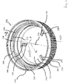
Fig. 1 shows a perspective view onto the cap according to the invention, -
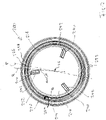
Fig. 2 shows a top view onto the cap ofFig. 1 . -
Fig. 1 shows ascrew cap 200 for containers with a threaded neck portion. Thescrew cap 200 has abase portion 210 comprising atop surface 212 and abottom surface 214, thebottom surface 214 having acenter 216. Thescrew cap 200 has anannular portion 220 raised from thebase portion 210, theannular portion 220 having aninner surface 224 and anouter surface 222. Thescrew cap 200 has a threadedportion 252 arranged on theinner surface 224 of theannular portion 220. Thethread 218 extends from astart 226 into a first circumferential direction A around theinner surface 224, thestart 226 being that part of thethread 218, where the material of which thethread 218 is made, starts to rise from theinner surface 224. Thethread 218 has a section of constant height, where the material that makes up thethread 218 in that section rises aboveinner surface 224 with a constant height, but thethread 218 in this design has a startingportion 228, where the material that makes thethread 218 in said startingportion 228 rises ramp-like. Thestart 226 is the point where the ramp starts to rise from theinner surface 224 - The
screw cap 200 anengagement portion 240 arranged on thebottom surface 214 and projecting from thebottom surface 214, theengagement portion 240 having a reference line R that runs along thebottom surface 214 and crosses thecenter 216, whereby all material that makes up theengagement portion 240 is arranged on one side of the reference line R, the reference line R touching at least one point of material that makes up theengagement portion 240. In the design shown inFig. 1 theengagement portion 240 is a rectangular block and the reference line R touches the inner most corner of the rectangular block. - The angle between
- a plane P (symbolized by the dashed line that shows where the plane P would intersect the screw cap 200) that contains the
center 216 and thestart 226 and is orientated perpendicular to thebottom surface 224 and - the reference line R is larger than 0° and smaller than 30°. In the embodiment shown in
Fig. 1 it is about 5°. - The
bottom surface 214 is a circular surface and thecenter 216 is the center of the circle. - Three
engagement portions 240 are arranged on thebottom surface 214. - The material that makes up the
engagement portion 240 is arranged on one side of the reference line R and the plane P that contains thecenter 216 and thestart 226 and is orientated perpendicular to thebottom surface 224 is arranged on the other side of the reference line R. - The
tread 218 extends away from the plane P in a direction away from the reference line R. - The
thread 218 and theengagement portion 240 are parts of an one piece element. - A
recess 242 is arranged next to theengagement portion 240.
Claims (7)
- Screw cap (200) for containers with a threaded neck portion, comprising:- a base portion (210) comprising a top surface (212) and a bottom surface (214), the bottom surface (214) having a center (216);- an annular portion (220) raised from the base portion (210), the annular portion having (220) an inner surface (224) and an outer surface (222);- a threaded portion (252) arranged on the inner surface (224) of the annular portion (220), the threaded portion (252) having at least on thread (218), the thread (218) extending from a start (226) into a first circumferential direction (A) around the inner surface (224), the start (226) being that part of the thread (218), where the material of which the thread is made, starts to rise from the inner surface (224),- an engagement portion (240) arranged on the bottom surface (214) and projecting from the bottom surface (214), the engagement portion (240) having a reference line (R) that runs along the bottom surface (214) and crosses the center (216), whereby all material that makes up the engagement portion (240) is arranged on one side of the reference line (R), the reference line (R) touching at least one point of material that makes up the engagement portion (240),characterized in that the angle between• a plane (P) that contains the center (216) and the start (226) and is orientated perpendicular to the bottom surface (214) and• the reference line (R)whereby the material that makes up the engagement portion (240) is arranged on one side of the reference line (R) and the plane (P) that contains the center (216) and the start (226) and is orientated perpendicular to the bottom surface (214) is arranged on the other side of the reference line (R) and the thread (218) extends away from the plane (P) in a direction away from the reference line (R).
is larger than 0° and smaller than 30°, - Screw cap according to claim 1, characterized in that the angle between• a plane (P) that contains the center (216) and the start (226) and is orientated perpendicular to the bottom surface (224) and• the reference line (R)
is larger than 2° and smaller than 26°. - Screw cap according to claim 1 or 2, characterized in that the bottom surface (214) is a circular surface and that the center (216) is the center of the circle.
- Screw cap according to any one of claims 1 to 3, characterized in that three engagement portions (240) are arranged on the bottom surface (214).
- Screw cap according to any one of claims 1 to 4, characterized in that the thread (218) and the engagement portion (240) are parts of an one piece element.
- Screw cap according to any one of claims 1 to 5, characterized in that a recess (242) is arranged next to the engagement portion (240).
- Screw cap according to any one of claims 1 to 6, characterized in that the engagement portion (240) is a rectangular block.
Priority Applications (2)
| Application Number | Priority Date | Filing Date | Title |
|---|---|---|---|
| RS20221034A RS63722B1 (en) | 2020-10-16 | 2021-10-15 | Screw cap |
| HRP20221364TT HRP20221364T1 (en) | 2020-10-16 | 2021-10-15 | Screw cap |
Applications Claiming Priority (3)
| Application Number | Priority Date | Filing Date | Title |
|---|---|---|---|
| EP20202258 | 2020-10-16 | ||
| DE202020004567.5U DE202020004567U1 (en) | 2020-10-16 | 2020-10-30 | Screw cap |
| PCT/EP2021/078682 WO2022079281A1 (en) | 2020-10-16 | 2021-10-15 | Screw cap |
Publications (2)
| Publication Number | Publication Date |
|---|---|
| EP4010262A1 EP4010262A1 (en) | 2022-06-15 |
| EP4010262B1 true EP4010262B1 (en) | 2022-11-02 |
Family
ID=73005299
Family Applications (1)
| Application Number | Title | Priority Date | Filing Date |
|---|---|---|---|
| EP21794360.4A Active EP4010262B1 (en) | 2020-10-16 | 2021-10-15 | Screw cap |
Country Status (12)
| Country | Link |
|---|---|
| US (1) | US20230382601A1 (en) |
| EP (1) | EP4010262B1 (en) |
| CA (1) | CA3195547A1 (en) |
| DE (1) | DE202020004567U1 (en) |
| DK (1) | DK4010262T3 (en) |
| ES (1) | ES2930043T3 (en) |
| HR (1) | HRP20221364T1 (en) |
| HU (1) | HUE060659T2 (en) |
| PL (1) | PL4010262T3 (en) |
| PT (1) | PT4010262T (en) |
| RS (1) | RS63722B1 (en) |
| WO (1) | WO2022079281A1 (en) |
Families Citing this family (4)
| Publication number | Priority date | Publication date | Assignee | Title |
|---|---|---|---|---|
| US20160332783A1 (en) * | 2015-05-11 | 2016-11-17 | Silgan White Cap LLC | Lightweight Closure with Tamper Band |
| USD1063612S1 (en) * | 2020-09-28 | 2025-02-25 | Closure Systems International Inc. | Closure with tamper-evident band |
| USD1063613S1 (en) * | 2020-09-28 | 2025-02-25 | Closure Systems International Inc. | Closure with tamper-evident band |
| DE202022106061U1 (en) | 2022-10-27 | 2023-02-02 | Paccor Packaging Gmbh | screw cap |
Family Cites Families (1)
| Publication number | Priority date | Publication date | Assignee | Title |
|---|---|---|---|---|
| RU2725362C2 (en) | 2015-01-23 | 2020-07-02 | Тетра Лаваль Холдингз Энд Файнэнс С.А. | Screw cap, instrument and method of cap screwing onto container |
-
2020
- 2020-10-30 DE DE202020004567.5U patent/DE202020004567U1/en active Active
-
2021
- 2021-10-15 DK DK21794360.4T patent/DK4010262T3/en active
- 2021-10-15 HU HUE21794360A patent/HUE060659T2/en unknown
- 2021-10-15 CA CA3195547A patent/CA3195547A1/en active Pending
- 2021-10-15 PL PL21794360.4T patent/PL4010262T3/en unknown
- 2021-10-15 HR HRP20221364TT patent/HRP20221364T1/en unknown
- 2021-10-15 WO PCT/EP2021/078682 patent/WO2022079281A1/en not_active Ceased
- 2021-10-15 RS RS20221034A patent/RS63722B1/en unknown
- 2021-10-15 EP EP21794360.4A patent/EP4010262B1/en active Active
- 2021-10-15 ES ES21794360T patent/ES2930043T3/en active Active
- 2021-10-15 US US18/248,287 patent/US20230382601A1/en not_active Abandoned
- 2021-10-15 PT PT217943604T patent/PT4010262T/en unknown
Also Published As
| Publication number | Publication date |
|---|---|
| DE202020004567U1 (en) | 2021-01-22 |
| HRP20221364T1 (en) | 2023-01-06 |
| HUE060659T2 (en) | 2023-04-28 |
| RS63722B1 (en) | 2022-12-30 |
| DK4010262T3 (en) | 2022-11-21 |
| US20230382601A1 (en) | 2023-11-30 |
| PL4010262T3 (en) | 2022-12-27 |
| ES2930043T3 (en) | 2022-12-05 |
| PT4010262T (en) | 2022-11-17 |
| CA3195547A1 (en) | 2022-04-21 |
| EP4010262A1 (en) | 2022-06-15 |
| WO2022079281A1 (en) | 2022-04-21 |
Similar Documents
| Publication | Publication Date | Title |
|---|---|---|
| WO2022079281A1 (en) | Screw cap | |
| EP2720959B1 (en) | Closure | |
| US9790005B2 (en) | Plastic closure with enhanced performance | |
| US4349119A (en) | Container construction | |
| US6968966B2 (en) | Tamper-indicating closure with lugs on a stop flange for spacing the flange from the finish of a container | |
| KR100538681B1 (en) | Plastic container with snap lid | |
| US9650170B2 (en) | Container with arcuate sidewall panels | |
| JPH07112868B2 (en) | Plastic gas vent lid | |
| CA2467157A1 (en) | User-friendly bottle and closure thread assembly | |
| CN1462251A (en) | Blow molding bottle | |
| US11130608B2 (en) | Square bottle | |
| US20020011458A1 (en) | Closure having an improved thread design | |
| JP7149747B2 (en) | square bottle | |
| US4448319A (en) | Screw cap | |
| JP7068910B2 (en) | Bottle | |
| EP1459991B1 (en) | Synthetic resin container | |
| JP6060576B2 (en) | Plastic container | |
| US20070210027A1 (en) | Child-Resistant Package | |
| US20190210777A1 (en) | Child-Resistant Large Mouth Container | |
| US8056758B2 (en) | Non-cylindrical container and lid | |
| WO2015185465A1 (en) | A closure for a container, a tamper indicating band, a combination and a method | |
| EP3533638B1 (en) | Tyre | |
| US5480028A (en) | Stackable plastic container package | |
| US20060151423A1 (en) | Closure having tapered sealing plug | |
| US10723517B2 (en) | Stackable molded cap |
Legal Events
| Date | Code | Title | Description |
|---|---|---|---|
| REG | Reference to a national code |
Ref country code: HR Ref legal event code: TUEP Ref document number: P20221364T Country of ref document: HR |
|
| STAA | Information on the status of an ep patent application or granted ep patent |
Free format text: STATUS: UNKNOWN |
|
| STAA | Information on the status of an ep patent application or granted ep patent |
Free format text: STATUS: THE INTERNATIONAL PUBLICATION HAS BEEN MADE |
|
| PUAI | Public reference made under article 153(3) epc to a published international application that has entered the european phase |
Free format text: ORIGINAL CODE: 0009012 |
|
| STAA | Information on the status of an ep patent application or granted ep patent |
Free format text: STATUS: REQUEST FOR EXAMINATION WAS MADE |
|
| 17P | Request for examination filed |
Effective date: 20220214 |
|
| AK | Designated contracting states |
Kind code of ref document: A1 Designated state(s): AL AT BE BG CH CY CZ DE DK EE ES FI FR GB GR HR HU IE IS IT LI LT LU LV MC MK MT NL NO PL PT RO RS SE SI SK SM TR |
|
| GRAP | Despatch of communication of intention to grant a patent |
Free format text: ORIGINAL CODE: EPIDOSNIGR1 |
|
| STAA | Information on the status of an ep patent application or granted ep patent |
Free format text: STATUS: GRANT OF PATENT IS INTENDED |
|
| INTG | Intention to grant announced |
Effective date: 20220715 |
|
| GRAS | Grant fee paid |
Free format text: ORIGINAL CODE: EPIDOSNIGR3 |
|
| GRAA | (expected) grant |
Free format text: ORIGINAL CODE: 0009210 |
|
| STAA | Information on the status of an ep patent application or granted ep patent |
Free format text: STATUS: THE PATENT HAS BEEN GRANTED |
|
| AK | Designated contracting states |
Kind code of ref document: B1 Designated state(s): AL AT BE BG CH CY CZ DE DK EE ES FI FR GB GR HR HU IE IS IT LI LT LU LV MC MK MT NL NO PL PT RO RS SE SI SK SM TR |
|
| DAV | Request for validation of the european patent (deleted) | ||
| DAX | Request for extension of the european patent (deleted) | ||
| REG | Reference to a national code |
Ref country code: GB Ref legal event code: FG4D |
|
| REG | Reference to a national code |
Ref country code: CH Ref legal event code: EP Ref country code: AT Ref legal event code: REF Ref document number: 1528608 Country of ref document: AT Kind code of ref document: T Effective date: 20221115 |
|
| REG | Reference to a national code |
Ref country code: PT Ref legal event code: SC4A Ref document number: 4010262 Country of ref document: PT Date of ref document: 20221117 Kind code of ref document: T Free format text: AVAILABILITY OF NATIONAL TRANSLATION Effective date: 20221111 Ref country code: DE Ref legal event code: R096 Ref document number: 602021000689 Country of ref document: DE |
|
| REG | Reference to a national code |
Ref country code: DK Ref legal event code: T3 Effective date: 20221116 |
|
| REG | Reference to a national code |
Ref country code: ES Ref legal event code: FG2A Ref document number: 2930043 Country of ref document: ES Kind code of ref document: T3 Effective date: 20221205 |
|
| REG | Reference to a national code |
Ref country code: SE Ref legal event code: TRGR |
|
| REG | Reference to a national code |
Ref country code: NL Ref legal event code: FP Ref country code: IE Ref legal event code: FG4D |
|
| REG | Reference to a national code |
Ref country code: NO Ref legal event code: T2 Effective date: 20221102 |
|
| REG | Reference to a national code |
Ref country code: GR Ref legal event code: EP Ref document number: 20220402241 Country of ref document: GR Effective date: 20221212 |
|
| REG | Reference to a national code |
Ref country code: HR Ref legal event code: T1PR Ref document number: P20221364 Country of ref document: HR |
|
| REG | Reference to a national code |
Ref country code: SK Ref legal event code: T3 Ref document number: E 40783 Country of ref document: SK |
|
| REG | Reference to a national code |
Ref country code: LT Ref legal event code: MG9D |
|
| PG25 | Lapsed in a contracting state [announced via postgrant information from national office to epo] |
Ref country code: LT Free format text: LAPSE BECAUSE OF FAILURE TO SUBMIT A TRANSLATION OF THE DESCRIPTION OR TO PAY THE FEE WITHIN THE PRESCRIBED TIME-LIMIT Effective date: 20221102 |
|
| REG | Reference to a national code |
Ref country code: HU Ref legal event code: AG4A Ref document number: E060659 Country of ref document: HU |
|
| PG25 | Lapsed in a contracting state [announced via postgrant information from national office to epo] |
Ref country code: LV Free format text: LAPSE BECAUSE OF FAILURE TO SUBMIT A TRANSLATION OF THE DESCRIPTION OR TO PAY THE FEE WITHIN THE PRESCRIBED TIME-LIMIT Effective date: 20221102 Ref country code: IS Free format text: LAPSE BECAUSE OF FAILURE TO SUBMIT A TRANSLATION OF THE DESCRIPTION OR TO PAY THE FEE WITHIN THE PRESCRIBED TIME-LIMIT Effective date: 20230302 |
|
| P01 | Opt-out of the competence of the unified patent court (upc) registered |
Effective date: 20230504 |
|
| PG25 | Lapsed in a contracting state [announced via postgrant information from national office to epo] |
Ref country code: SM Free format text: LAPSE BECAUSE OF FAILURE TO SUBMIT A TRANSLATION OF THE DESCRIPTION OR TO PAY THE FEE WITHIN THE PRESCRIBED TIME-LIMIT Effective date: 20221102 Ref country code: RO Free format text: LAPSE BECAUSE OF FAILURE TO SUBMIT A TRANSLATION OF THE DESCRIPTION OR TO PAY THE FEE WITHIN THE PRESCRIBED TIME-LIMIT Effective date: 20221102 Ref country code: EE Free format text: LAPSE BECAUSE OF FAILURE TO SUBMIT A TRANSLATION OF THE DESCRIPTION OR TO PAY THE FEE WITHIN THE PRESCRIBED TIME-LIMIT Effective date: 20221102 |
|
| REG | Reference to a national code |
Ref country code: DE Ref legal event code: R097 Ref document number: 602021000689 Country of ref document: DE |
|
| PG25 | Lapsed in a contracting state [announced via postgrant information from national office to epo] |
Ref country code: AL Free format text: LAPSE BECAUSE OF FAILURE TO SUBMIT A TRANSLATION OF THE DESCRIPTION OR TO PAY THE FEE WITHIN THE PRESCRIBED TIME-LIMIT Effective date: 20221102 |
|
| PLBE | No opposition filed within time limit |
Free format text: ORIGINAL CODE: 0009261 |
|
| STAA | Information on the status of an ep patent application or granted ep patent |
Free format text: STATUS: NO OPPOSITION FILED WITHIN TIME LIMIT |
|
| 26N | No opposition filed |
Effective date: 20230803 |
|
| REG | Reference to a national code |
Ref country code: HR Ref legal event code: ODRP Ref document number: P20221364 Country of ref document: HR Payment date: 20231003 Year of fee payment: 3 |
|
| PG25 | Lapsed in a contracting state [announced via postgrant information from national office to epo] |
Ref country code: MC Free format text: LAPSE BECAUSE OF FAILURE TO SUBMIT A TRANSLATION OF THE DESCRIPTION OR TO PAY THE FEE WITHIN THE PRESCRIBED TIME-LIMIT Effective date: 20221102 |
|
| PG25 | Lapsed in a contracting state [announced via postgrant information from national office to epo] |
Ref country code: LU Free format text: LAPSE BECAUSE OF NON-PAYMENT OF DUE FEES Effective date: 20231015 |
|
| PG25 | Lapsed in a contracting state [announced via postgrant information from national office to epo] |
Ref country code: LU Free format text: LAPSE BECAUSE OF NON-PAYMENT OF DUE FEES Effective date: 20231015 |
|
| REG | Reference to a national code |
Ref country code: HR Ref legal event code: ODRP Ref document number: P20221364 Country of ref document: HR Payment date: 20241004 Year of fee payment: 4 |
|
| PG25 | Lapsed in a contracting state [announced via postgrant information from national office to epo] |
Ref country code: BG Free format text: LAPSE BECAUSE OF FAILURE TO SUBMIT A TRANSLATION OF THE DESCRIPTION OR TO PAY THE FEE WITHIN THE PRESCRIBED TIME-LIMIT Effective date: 20221102 |
|
| PG25 | Lapsed in a contracting state [announced via postgrant information from national office to epo] |
Ref country code: BG Free format text: LAPSE BECAUSE OF FAILURE TO SUBMIT A TRANSLATION OF THE DESCRIPTION OR TO PAY THE FEE WITHIN THE PRESCRIBED TIME-LIMIT Effective date: 20221102 |
|
| REG | Reference to a national code |
Ref country code: DE Ref legal event code: R082 Ref document number: 602021000689 Country of ref document: DE Representative=s name: WEHNER, JOHANNES, DR., DE |
|
| PG25 | Lapsed in a contracting state [announced via postgrant information from national office to epo] |
Ref country code: CY Free format text: LAPSE BECAUSE OF FAILURE TO SUBMIT A TRANSLATION OF THE DESCRIPTION OR TO PAY THE FEE WITHIN THE PRESCRIBED TIME-LIMIT; INVALID AB INITIO Effective date: 20211015 |
|
| REG | Reference to a national code |
Ref country code: CH Ref legal event code: U11 Free format text: ST27 STATUS EVENT CODE: U-0-0-U10-U11 (AS PROVIDED BY THE NATIONAL OFFICE) Effective date: 20251101 |
|
| REG | Reference to a national code |
Ref country code: HR Ref legal event code: ODRP Ref document number: P20221364 Country of ref document: HR Payment date: 20251021 Year of fee payment: 5 |
|
| PGFP | Annual fee paid to national office [announced via postgrant information from national office to epo] |
Ref country code: HU Payment date: 20251029 Year of fee payment: 5 |
|
| PGFP | Annual fee paid to national office [announced via postgrant information from national office to epo] |
Ref country code: NL Payment date: 20251026 Year of fee payment: 5 |
|
| PGFP | Annual fee paid to national office [announced via postgrant information from national office to epo] |
Ref country code: PT Payment date: 20251020 Year of fee payment: 5 |
|
| PGFP | Annual fee paid to national office [announced via postgrant information from national office to epo] |
Ref country code: DE Payment date: 20251029 Year of fee payment: 5 |
|
| PGFP | Annual fee paid to national office [announced via postgrant information from national office to epo] |
Ref country code: GB Payment date: 20251027 Year of fee payment: 5 |
|
| PGFP | Annual fee paid to national office [announced via postgrant information from national office to epo] |
Ref country code: NO Payment date: 20251029 Year of fee payment: 5 |
|
| PGFP | Annual fee paid to national office [announced via postgrant information from national office to epo] |
Ref country code: AT Payment date: 20260113 Year of fee payment: 5 |
|
| PGFP | Annual fee paid to national office [announced via postgrant information from national office to epo] |
Ref country code: FI Payment date: 20251027 Year of fee payment: 5 Ref country code: DK Payment date: 20251027 Year of fee payment: 5 Ref country code: IT Payment date: 20251021 Year of fee payment: 5 |
|
| PGFP | Annual fee paid to national office [announced via postgrant information from national office to epo] |
Ref country code: FR Payment date: 20251027 Year of fee payment: 5 Ref country code: HR Payment date: 20251021 Year of fee payment: 5 |
|
| PGFP | Annual fee paid to national office [announced via postgrant information from national office to epo] |
Ref country code: GR Payment date: 20251029 Year of fee payment: 5 Ref country code: BE Payment date: 20251027 Year of fee payment: 5 Ref country code: TR Payment date: 20251023 Year of fee payment: 5 |
|
| PGFP | Annual fee paid to national office [announced via postgrant information from national office to epo] |
Ref country code: CH Payment date: 20251101 Year of fee payment: 5 Ref country code: SE Payment date: 20251027 Year of fee payment: 5 |
|
| PGFP | Annual fee paid to national office [announced via postgrant information from national office to epo] |
Ref country code: IE Payment date: 20251027 Year of fee payment: 5 Ref country code: CZ Payment date: 20251020 Year of fee payment: 5 |
|
| PGFP | Annual fee paid to national office [announced via postgrant information from national office to epo] |
Ref country code: PL Payment date: 20251021 Year of fee payment: 5 |
|
| PGFP | Annual fee paid to national office [announced via postgrant information from national office to epo] |
Ref country code: SK Payment date: 20251020 Year of fee payment: 5 |
|
| PGFP | Annual fee paid to national office [announced via postgrant information from national office to epo] |
Ref country code: RS Payment date: 20251020 Year of fee payment: 5 |
|
| PGFP | Annual fee paid to national office [announced via postgrant information from national office to epo] |
Ref country code: SI Payment date: 20251017 Year of fee payment: 5 Ref country code: ES Payment date: 20251103 Year of fee payment: 5 |