EP4010208B1 - Tire electronics assembly - Google Patents
Tire electronics assembly Download PDFInfo
- Publication number
- EP4010208B1 EP4010208B1 EP20849926.9A EP20849926A EP4010208B1 EP 4010208 B1 EP4010208 B1 EP 4010208B1 EP 20849926 A EP20849926 A EP 20849926A EP 4010208 B1 EP4010208 B1 EP 4010208B1
- Authority
- EP
- European Patent Office
- Prior art keywords
- modules
- base
- tire
- mechanical attachment
- attachment element
- Prior art date
- Legal status (The legal status is an assumption and is not a legal conclusion. Google has not performed a legal analysis and makes no representation as to the accuracy of the status listed.)
- Active
Links
Images


Classifications
-
- B—PERFORMING OPERATIONS; TRANSPORTING
- B29—WORKING OF PLASTICS; WORKING OF SUBSTANCES IN A PLASTIC STATE IN GENERAL
- B29D—PRODUCING PARTICULAR ARTICLES FROM PLASTICS OR FROM SUBSTANCES IN A PLASTIC STATE
- B29D30/00—Producing pneumatic or solid tyres or parts thereof
- B29D30/0061—Accessories, details or auxiliary operations not otherwise provided for
-
- B—PERFORMING OPERATIONS; TRANSPORTING
- B60—VEHICLES IN GENERAL
- B60C—VEHICLE TYRES; TYRE INFLATION; TYRE CHANGING; CONNECTING VALVES TO INFLATABLE ELASTIC BODIES IN GENERAL; DEVICES OR ARRANGEMENTS RELATED TO TYRES
- B60C19/00—Tyre parts or constructions not otherwise provided for
-
- B—PERFORMING OPERATIONS; TRANSPORTING
- B60—VEHICLES IN GENERAL
- B60C—VEHICLE TYRES; TYRE INFLATION; TYRE CHANGING; CONNECTING VALVES TO INFLATABLE ELASTIC BODIES IN GENERAL; DEVICES OR ARRANGEMENTS RELATED TO TYRES
- B60C23/00—Devices for measuring, signalling, controlling, or distributing tyre pressure or temperature, specially adapted for mounting on vehicles; Arrangement of tyre inflating devices on vehicles, e.g. of pumps or of tanks; Tyre cooling arrangements
- B60C23/02—Signalling devices actuated by tyre pressure
- B60C23/04—Signalling devices actuated by tyre pressure mounted on the wheel or tyre
- B60C23/0491—Constructional details of means for attaching the control device
- B60C23/0493—Constructional details of means for attaching the control device for attachment on the tyre
-
- B—PERFORMING OPERATIONS; TRANSPORTING
- B29—WORKING OF PLASTICS; WORKING OF SUBSTANCES IN A PLASTIC STATE IN GENERAL
- B29D—PRODUCING PARTICULAR ARTICLES FROM PLASTICS OR FROM SUBSTANCES IN A PLASTIC STATE
- B29D30/00—Producing pneumatic or solid tyres or parts thereof
- B29D30/0061—Accessories, details or auxiliary operations not otherwise provided for
- B29D2030/0072—Attaching fasteners to tyres, e.g. patches, in order to connect devices to tyres
-
- B—PERFORMING OPERATIONS; TRANSPORTING
- B60—VEHICLES IN GENERAL
- B60C—VEHICLE TYRES; TYRE INFLATION; TYRE CHANGING; CONNECTING VALVES TO INFLATABLE ELASTIC BODIES IN GENERAL; DEVICES OR ARRANGEMENTS RELATED TO TYRES
- B60C19/00—Tyre parts or constructions not otherwise provided for
- B60C2019/004—Tyre sensors other than for detecting tyre pressure
Definitions
- the lower mechanical attachment element on each one of the modules is configured to attach to the upper mechanical attachment element on any other one of the modules.
- the modules are interchangeably mechanically attachable to each other in a stacked arrangement.
- the lower mechanical attachment element on each one of the modules is also configured to attach to the mechanical attachment element on the base.
- the modules are thus mechanically attachable to the base interchangeably with each other, which enables any one of the modules to be installed as the lowermost module in the stacked arrangement.
Landscapes
- Engineering & Computer Science (AREA)
- Mechanical Engineering (AREA)
- Arrangements For Transmission Of Measured Signals (AREA)
- Measuring Fluid Pressure (AREA)
- Tires In General (AREA)
Description
- This technology includes electronic devices for sensing conditions of a tire on a vehicle.
- Electronic devices can be used to sense conditions of a tire on a vehicle. Such devices include air pressure and temperature sensors that are mounted inside the tire, and also include radio frequency transmitters for transmitting pressure and temperature signals from the tire to the vehicle.
An apparatus for use with a tire including electronic devices are known, for instance, from documentUS 2011/132649 A1 . Furthermore, apparatuses for use with a tire having mechanical attachment elements are known, for instance, fromUS 4 133 592 A . - An electronics assembly is provided for use with a tire according to claim 1. The assembly includes a base and a plurality of modules. The base is configured for mechanical attachment to the tire and includes an electronic device. The base also includes a mechanical attachment element. Each module includes an electronic device, a lower mechanical attachment element, and an upper mechanical attachment element.
- The lower mechanical attachment element on each one of the modules is configured to attach to the upper mechanical attachment element on any other one of the modules. In this configuration, the modules are interchangeably mechanically attachable to each other in a stacked arrangement.
- The lower mechanical attachment element on each one of the modules is also configured to attach to the mechanical attachment element on the base. The modules are thus mechanically attachable to the base interchangeably with each other, which enables any one of the modules to be installed as the lowermost module in the stacked arrangement.
- Additionally, a lower electrical contact on each one of the modules is configured to electrically connect with an upper electrical contact on any other one of the modules. In this configuration, the modules are interchangeably electrically connectable with each other in the stacked arrangement. The lower electrical contact on each one of the modules is further configured to connect electrically with an electrical contact on the base, whereby the modules are interchangeably electrically connectable with the base as the lowermost module in the stacked arrangement.
- In an illustrated embodiment, the base is configured to overlie an interior surface of the tire. Another illustrated embodiment includes a base configured for embedded installation within the tire. In yet another embodiment the base is configured for installation between layers of the tire.
-
-
FIG. 1 is a schematic sectional view of a tire and an electronics assembly for use with the tire. -
FIG. 2 is an exploded view of parts of the electronic assembly ofFIG. 1 . -
FIG. 3 is a schematic sectional view of an alternative embodiment of a tire and an electronics assembly for use with the tire. -
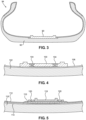
FIG. 4 is a schematic sectional view of alternative embodiment of a tire and an electronics assembly for use with the tire. -
FIG. 5 is a schematic sectional view of an alternative embodiment of a tire and an electronics assembly for use with the tire. -
FIG. 6 is a schematic sectional view of an alternative embodiment of a tire and an electronics assembly for use with the tire. -
FIG. 7 is a schematic sectional view of an alternative embodiment of a tire and an electronics assembly for use with the tire. - As shown in
FIG. 1 , apneumatic tire 10 includes a tread 12,bead portions 14, andsidewalls 16 interconnecting the tread 12 with thebead portions 14. Aninner surface 18 of thetire 10 defines the periphery of acavity 21 within thetire 10. Theinner surface 18 in this example is provided by aninnerliner 22 that reaches fully throughout the interior of the tread 12, thebead portions 14, and thesidewalls 16. - Also shown in
FIG. 1 is anelectronics assembly 30 for use with thetire 10. Theelectronics assembly 30 in this example includes abase 32 andmultiple modules 34. As shown schematically inFIG. 2 , eachmodule 34 includes one or moreelectronic devices 36. Thedevices 36 in themodules 34 may include air pressure sensors, temperature sensors, power generation or storage devices, radio frequency transmitters, radio frequency receivers, and/or any other electronic devices suitable for obtaining and/or providing information relating to conditions of thetire 10. - The
base 32 also includes one or more electronic devices 40 (FIG. 2 ). These may include anelectronic device 40 configured to provide a unique identification signal for identifying thetire 10 in distinction from another tire on the same vehicle or a different vehicle. Otherelectronic devices 40 in thebase 32 may be configured to receive and/or transmit signals between thedevices 40 in the base, thedevices 36 in themodules 34, and the vehicle. In each case, theelectronic devices - As shown separately in
FIG. 2 , each of themodules 34 ofFIG. 1 includes a panel-shaped housing 50 containing the respectiveelectronic devices 36. Uppermechanical attachment elements 52 face upward from eachhousing 50. Lowermechanical attachment elements 54 face downward from eachhousing 50. The lowermechanical attachment elements 54 on each one of thehousings 50 are configured to releasably mechanically attach to the uppermechanical attachment elements 52 on any other one of thehousings 50. Accordingly, themodules 34 are interchangeably mechanically attachable to each other in a stacked arrangement, as shown for example inFIG. 1 . Themechanical attachment elements - The
base 32 of theelectronics assembly 30 is attached to thetire 10 at the interior of thetire 10. As shown schematically inFIG. 2 , thebase 32 includes a panel-shaped housing 60 containing theelectronic devices 40. Thehousing 60 has alower side surface 62 adhered to theinner surface 18 of thetire 10.Mechanical attachment elements 64 face upward from thehousing 60. The lowermechanical attachment elements 54 on any one of themodules 34 can releasably mechanically attach to themechanical attachment elements 64 on thebase 32. This enables any one of themodules 34 to be installed as thelowermost module 34 in the stack shown inFIG. 1 . - In addition to the
mechanical attachment elements module 34 also has upperelectrical contacts 72 facing upward from thehousing 50, and lowerelectrical contacts 74 facing downward from thehousing 50. The lowerelectrical contacts 74 on each one of themodules 34 are configured to releasably electrically connect with the upperelectrical contacts 72 on any other one of thehousings 50. This enables themodules 34 to be interchangeably electrically connectable with each other in the stack ofFIG. 1 . Theelectrical contacts mechanical attachment elements electrical contacts - The
base 32 haselectrical contacts 76 facing upward from thehousing 60. Like theelectrical contacts modules 34, theelectrical contacts 76 on thebase 32 can include pin and socket connectors that double as themechanical attachment elements 64. The lowerelectrical contacts 74 on any one of themodule housings 50 can releasably electrically connect with theelectrical contacts 76 on thebase 32. Any one of themodules 34 can thus function as thelowermost module 34 in the stack ofFIG. 1 . - As further shown schematically in
FIG. 2 , theelectrical devices 36 in themodules 34 are mounted on printedcircuit boards 80. Each printedcircuit board 80 is configured to electrically connect thedevices 36 in therespective module 34 in series with thedevices 36 in any other two of themodules 34. Each printedcircuit board 80 is further configured to electrically connect thedevices 36 in therespective module 34 in series with thedevices 40 in thebase 32. -
FIGS. 3-5 show alternative embodiments of a base for use with modules like themodules 34 ofFIGS. 1 and2 . As shown inFIG. 3 , a base 90 that is substantially the same as thebase 32 is embedded within the body of the tire in thetread portion 92 of atire 94. As shown inFIG. 4 , abase 100 is attached to atire 102 byfasteners 104 that are attached to aninnerliner 106. As shown inFIG. 5 , asupport platform 110 is installed betweenlayers tire 116. The base 118 in this embodiment is mounted over theinnermost layer 112 of thetire 116 and is retained in place byfasteners 120 projecting from thesupport platform 110 through theinnermost layer 112. - In the alternative embodiment of
FIG. 6 , themodules 121 have uppermechanical attachment elements 122 andlower attachment elements 124. One of the lowermechanical attachment elements 124 on eachmodule 121 is configured as a flexible hook for snapping into releasable interlocked engagement with one of the uppermechanical attachment elements 122 on any other one of themodules 121. Thoselower attachment elements 124 can likewise snap into engagement withcomplimentary attachment element 128 on abase structure 130. The embodiment ofFIG. 7 also has flexiblemechanical attachment elements 140 for eachmodule 142 to snap into engagement with anyother module 142 or with the base structure 144.
Claims (7)
- An apparatus for use with a tire (10, 94, 102, 116), comprising:a base (32, 90, 100, 118) configured for mechanical attachment to the tire (10, 94, 102, 116), the base (32, 90, 100, 118) including an electronic device (40) and a mechanical attachment element (64, 128); anda plurality of modules (34, 121, 142), each of which includes an electronic device (36), a lower mechanical attachment element (54, 124), and an upper mechanical attachment element (52, 122);wherein the lower mechanical attachment element (54, 124) on each one of the modules (34, 121, 142) is configured to mechanically attach to the upper mechanical attachment element (52, 122) on any other one of the modules (34, 121, 142), whereby the modules (34, 121, 142) are interchangeably mechanically attachable to each other; andthe lower mechanical attachment element (54, 124) on each one of the modules (34, 121, 142) is configured to mechanically attach to the mechanical attachment element (64, 128) on the base (32, 90, 100, 118), whereby the modules (34, 121, 142) are interchangeably mechanically attachable to the base (32, 90, 100, 118).
- An apparatus as defined in claim 1, wherein the electronic device (40) in the base (32, 90, 100, 118) is configured to provide a unique identification signal identifying the tire (10, 94, 102, 116).
- An apparatus as defined in claim 1 or claim 2, wherein the base (90) is configured for embedded installation within the tire (10, 94, 102, 116).
- An apparatus as defined in claim 1 or claim 2, wherein the base (118) is configured for installation between layers (112, 114) of the tire (10, 94, 102, 116).
- An apparatus as defined in any one of claims 1 to 4, wherein the base (32, 90, 100, 118) further includes an electrical contact (76), each module (34, 121, 142) includes a lower electrical contact (74), and each module (34, 121, 142) further includes an upper electrical contact (72);wherein the lower electrical contact (74) on each one of the modules (34, 121, 142) is configured to electrically connect with the upper electrical contact (72) on any other one of the modules (34, 121, 142), whereby the modules (34, 121, 142) are interchangeably electrically connectable with each other; andthe lower electrical contact (74) on each one of the modules (34, 121, 142) is configured to connect electrically with the electrical contact (76) on the base (32, 90, 100, 118), whereby the modules (34, 121, 142) are interchangeably electrically connectable with the base (32, 90, 100, 118).
- An apparatus as defined in claim 5, wherein each one of the modules (34, 121, 142) includes circuitry configured to electrically connect any other two of the modules (34, 121, 142) in series with one another.
- An apparatus as defined in claim 5, wherein each one of the modules (34, 121, 142) includes circuitry configured to electrically connect any one of the modules (34, 121, 142) in series with the base (32, 90, 100, 118).
Applications Claiming Priority (2)
| Application Number | Priority Date | Filing Date | Title |
|---|---|---|---|
| US201962882790P | 2019-08-05 | 2019-08-05 | |
| PCT/US2020/043807 WO2021025895A1 (en) | 2019-08-05 | 2020-07-28 | Tire electronics assembly |
Publications (3)
| Publication Number | Publication Date |
|---|---|
| EP4010208A1 EP4010208A1 (en) | 2022-06-15 |
| EP4010208A4 EP4010208A4 (en) | 2023-08-09 |
| EP4010208B1 true EP4010208B1 (en) | 2025-07-09 |
Family
ID=74503976
Family Applications (1)
| Application Number | Title | Priority Date | Filing Date |
|---|---|---|---|
| EP20849926.9A Active EP4010208B1 (en) | 2019-08-05 | 2020-07-28 | Tire electronics assembly |
Country Status (5)
| Country | Link |
|---|---|
| US (1) | US20220297484A1 (en) |
| EP (1) | EP4010208B1 (en) |
| JP (1) | JP7241231B2 (en) |
| CN (1) | CN114340916A (en) |
| WO (1) | WO2021025895A1 (en) |
Family Cites Families (13)
| Publication number | Priority date | Publication date | Assignee | Title |
|---|---|---|---|---|
| CA1063730A (en) * | 1975-11-11 | 1979-10-02 | Robert F. Cobaugh | Printed circuit board assembly |
| US20050076982A1 (en) * | 2003-10-09 | 2005-04-14 | Metcalf Arthur Richard | Post patch assembly for mounting devices in a tire interior |
| KR100555659B1 (en) * | 2003-12-22 | 2006-03-03 | 삼성전자주식회사 | Self-generated sensing module and tire pressure monitoring system using it |
| US8742265B2 (en) * | 2008-08-29 | 2014-06-03 | Compagnie Generale Des Etablissements Michelin | 1-D tire patch apparatus and methodology |
| JP5466777B1 (en) * | 2013-04-18 | 2014-04-09 | 株式会社ブリヂストン | Tire measuring instrument and tire measuring method |
| FR3028058B1 (en) | 2014-10-30 | 2016-12-09 | Continental Automotive France | METHOD FOR CONTROLLING A PROCESSOR OF AN ELECTRONIC HOUSING MOUNTED ON A WHEEL OF A MOTOR VEHICLE |
| FR3029845B1 (en) * | 2014-12-15 | 2017-08-11 | Michelin & Cie | PATCH FOR ELECTRONIC PNEUMATIC MODULE |
| KR101760872B1 (en) * | 2015-08-24 | 2017-07-24 | 한국타이어 주식회사 | Pneumatic tire comprising sensor patch and method for manufacturing the same |
| JP2017071341A (en) * | 2015-10-08 | 2017-04-13 | 株式会社デンソー | Tire mount sensor and sensor device used therefor |
| JP2017154631A (en) * | 2016-03-02 | 2017-09-07 | 株式会社ブリヂストン | Function component attachment member |
| JP2017156258A (en) | 2016-03-03 | 2017-09-07 | マツダ株式会社 | Tyre inflation pressure alarming device for wheeled vehicles |
| JP6331155B2 (en) * | 2016-03-03 | 2018-05-30 | マツダ株式会社 | Vehicle tire pressure alarm device |
| EP3264491A1 (en) * | 2016-06-28 | 2018-01-03 | Wattsun pop-up power B.V. | Modular energy system for storing and releasing energy |
-
2020
- 2020-07-28 US US17/631,884 patent/US20220297484A1/en active Pending
- 2020-07-28 JP JP2022506717A patent/JP7241231B2/en active Active
- 2020-07-28 WO PCT/US2020/043807 patent/WO2021025895A1/en not_active Ceased
- 2020-07-28 CN CN202080060593.4A patent/CN114340916A/en active Pending
- 2020-07-28 EP EP20849926.9A patent/EP4010208B1/en active Active
Also Published As
| Publication number | Publication date |
|---|---|
| CN114340916A (en) | 2022-04-12 |
| WO2021025895A1 (en) | 2021-02-11 |
| JP7241231B2 (en) | 2023-03-16 |
| BR112022002073A2 (en) | 2022-03-29 |
| EP4010208A1 (en) | 2022-06-15 |
| EP4010208A4 (en) | 2023-08-09 |
| US20220297484A1 (en) | 2022-09-22 |
| JP2022543599A (en) | 2022-10-13 |
Similar Documents
| Publication | Publication Date | Title |
|---|---|---|
| EP4010206B1 (en) | Tire electronics assembly | |
| US8113059B2 (en) | Circuit module | |
| US20040046649A1 (en) | Tire pressure monitoring system | |
| US20210394566A1 (en) | Functional component | |
| CN101198854A (en) | Use of Piezoelectric Sensors Attached to Electronic Package Housings | |
| EP3330930B1 (en) | A telematics device for a vehicle | |
| EP4010208B1 (en) | Tire electronics assembly | |
| US10704990B2 (en) | Spacer and sensor module for detecting a vibrational behavior of a mechanical component including the spacer | |
| US12508852B2 (en) | Tire electronics assembly apparatus having a module configured to releasably mechanically attach to the base of the tire | |
| US12157338B2 (en) | Daisy tire electronics assembly | |
| WO2018066012A1 (en) | On-board diagnostic device for vehicles | |
| US6935169B2 (en) | Tire pressure sensor array | |
| CN111146556B (en) | Antenna device and electronic system | |
| BR112022002073B1 (en) | DEVICE FOR USE WITH A TIRE | |
| CN217403648U (en) | Plate type tension sensor and engineering machinery | |
| BR112022002157B1 (en) | DEVICE FOR USE WITH A TIRE | |
| JP2016046791A (en) | Transmission device |
Legal Events
| Date | Code | Title | Description |
|---|---|---|---|
| STAA | Information on the status of an ep patent application or granted ep patent |
Free format text: STATUS: THE INTERNATIONAL PUBLICATION HAS BEEN MADE |
|
| PUAI | Public reference made under article 153(3) epc to a published international application that has entered the european phase |
Free format text: ORIGINAL CODE: 0009012 |
|
| STAA | Information on the status of an ep patent application or granted ep patent |
Free format text: STATUS: REQUEST FOR EXAMINATION WAS MADE |
|
| 17P | Request for examination filed |
Effective date: 20220215 |
|
| AK | Designated contracting states |
Kind code of ref document: A1 Designated state(s): AL AT BE BG CH CY CZ DE DK EE ES FI FR GB GR HR HU IE IS IT LI LT LU LV MC MK MT NL NO PL PT RO RS SE SI SK SM TR |
|
| DAV | Request for validation of the european patent (deleted) | ||
| DAX | Request for extension of the european patent (deleted) | ||
| A4 | Supplementary search report drawn up and despatched |
Effective date: 20230707 |
|
| RIC1 | Information provided on ipc code assigned before grant |
Ipc: B29D 30/00 20060101ALI20230703BHEP Ipc: B60C 23/04 20060101AFI20230703BHEP |
|
| GRAP | Despatch of communication of intention to grant a patent |
Free format text: ORIGINAL CODE: EPIDOSNIGR1 |
|
| STAA | Information on the status of an ep patent application or granted ep patent |
Free format text: STATUS: GRANT OF PATENT IS INTENDED |
|
| INTG | Intention to grant announced |
Effective date: 20250128 |
|
| GRAS | Grant fee paid |
Free format text: ORIGINAL CODE: EPIDOSNIGR3 |
|
| GRAA | (expected) grant |
Free format text: ORIGINAL CODE: 0009210 |
|
| STAA | Information on the status of an ep patent application or granted ep patent |
Free format text: STATUS: THE PATENT HAS BEEN GRANTED |
|
| P01 | Opt-out of the competence of the unified patent court (upc) registered |
Free format text: CASE NUMBER: APP_24149/2025 Effective date: 20250520 |
|
| AK | Designated contracting states |
Kind code of ref document: B1 Designated state(s): AL AT BE BG CH CY CZ DE DK EE ES FI FR GB GR HR HU IE IS IT LI LT LU LV MC MK MT NL NO PL PT RO RS SE SI SK SM TR |
|
| REG | Reference to a national code |
Ref country code: GB Ref legal event code: FG4D |
|
| REG | Reference to a national code |
Ref country code: CH Ref legal event code: EP |
|
| REG | Reference to a national code |
Ref country code: IE Ref legal event code: FG4D |
|
| REG | Reference to a national code |
Ref country code: DE Ref legal event code: R096 Ref document number: 602020054338 Country of ref document: DE |
|
| PGFP | Annual fee paid to national office [announced via postgrant information from national office to epo] |
Ref country code: DE Payment date: 20250724 Year of fee payment: 6 |
|
| PGFP | Annual fee paid to national office [announced via postgrant information from national office to epo] |
Ref country code: IT Payment date: 20250923 Year of fee payment: 6 |
|
| PGFP | Annual fee paid to national office [announced via postgrant information from national office to epo] |
Ref country code: FR Payment date: 20250820 Year of fee payment: 6 |
|
| REG | Reference to a national code |
Ref country code: NL Ref legal event code: MP Effective date: 20250709 |
|
| PG25 | Lapsed in a contracting state [announced via postgrant information from national office to epo] |
Ref country code: PT Free format text: LAPSE BECAUSE OF FAILURE TO SUBMIT A TRANSLATION OF THE DESCRIPTION OR TO PAY THE FEE WITHIN THE PRESCRIBED TIME-LIMIT Effective date: 20251110 |
|
| PG25 | Lapsed in a contracting state [announced via postgrant information from national office to epo] |
Ref country code: NL Free format text: LAPSE BECAUSE OF FAILURE TO SUBMIT A TRANSLATION OF THE DESCRIPTION OR TO PAY THE FEE WITHIN THE PRESCRIBED TIME-LIMIT Effective date: 20250709 |
|
| REG | Reference to a national code |
Ref country code: AT Ref legal event code: MK05 Ref document number: 1811543 Country of ref document: AT Kind code of ref document: T Effective date: 20250709 |
|
| PG25 | Lapsed in a contracting state [announced via postgrant information from national office to epo] |
Ref country code: IS Free format text: LAPSE BECAUSE OF FAILURE TO SUBMIT A TRANSLATION OF THE DESCRIPTION OR TO PAY THE FEE WITHIN THE PRESCRIBED TIME-LIMIT Effective date: 20251109 |
|
| PG25 | Lapsed in a contracting state [announced via postgrant information from national office to epo] |
Ref country code: NO Free format text: LAPSE BECAUSE OF FAILURE TO SUBMIT A TRANSLATION OF THE DESCRIPTION OR TO PAY THE FEE WITHIN THE PRESCRIBED TIME-LIMIT Effective date: 20251009 |
|
| REG | Reference to a national code |
Ref country code: LT Ref legal event code: MG9D |
|
| PG25 | Lapsed in a contracting state [announced via postgrant information from national office to epo] |
Ref country code: AT Free format text: LAPSE BECAUSE OF FAILURE TO SUBMIT A TRANSLATION OF THE DESCRIPTION OR TO PAY THE FEE WITHIN THE PRESCRIBED TIME-LIMIT Effective date: 20250709 |
|
| PG25 | Lapsed in a contracting state [announced via postgrant information from national office to epo] |
Ref country code: FI Free format text: LAPSE BECAUSE OF FAILURE TO SUBMIT A TRANSLATION OF THE DESCRIPTION OR TO PAY THE FEE WITHIN THE PRESCRIBED TIME-LIMIT Effective date: 20250709 |
|
| PG25 | Lapsed in a contracting state [announced via postgrant information from national office to epo] |
Ref country code: HR Free format text: LAPSE BECAUSE OF FAILURE TO SUBMIT A TRANSLATION OF THE DESCRIPTION OR TO PAY THE FEE WITHIN THE PRESCRIBED TIME-LIMIT Effective date: 20250709 |
|
| PG25 | Lapsed in a contracting state [announced via postgrant information from national office to epo] |
Ref country code: GR Free format text: LAPSE BECAUSE OF FAILURE TO SUBMIT A TRANSLATION OF THE DESCRIPTION OR TO PAY THE FEE WITHIN THE PRESCRIBED TIME-LIMIT Effective date: 20251010 |
|
| PG25 | Lapsed in a contracting state [announced via postgrant information from national office to epo] |
Ref country code: SE Free format text: LAPSE BECAUSE OF FAILURE TO SUBMIT A TRANSLATION OF THE DESCRIPTION OR TO PAY THE FEE WITHIN THE PRESCRIBED TIME-LIMIT Effective date: 20250709 |
|
| PG25 | Lapsed in a contracting state [announced via postgrant information from national office to epo] |
Ref country code: LV Free format text: LAPSE BECAUSE OF FAILURE TO SUBMIT A TRANSLATION OF THE DESCRIPTION OR TO PAY THE FEE WITHIN THE PRESCRIBED TIME-LIMIT Effective date: 20250709 |
|
| PG25 | Lapsed in a contracting state [announced via postgrant information from national office to epo] |
Ref country code: PL Free format text: LAPSE BECAUSE OF FAILURE TO SUBMIT A TRANSLATION OF THE DESCRIPTION OR TO PAY THE FEE WITHIN THE PRESCRIBED TIME-LIMIT Effective date: 20250709 Ref country code: BG Free format text: LAPSE BECAUSE OF FAILURE TO SUBMIT A TRANSLATION OF THE DESCRIPTION OR TO PAY THE FEE WITHIN THE PRESCRIBED TIME-LIMIT Effective date: 20250709 |
|
| PG25 | Lapsed in a contracting state [announced via postgrant information from national office to epo] |
Ref country code: RS Free format text: LAPSE BECAUSE OF FAILURE TO SUBMIT A TRANSLATION OF THE DESCRIPTION OR TO PAY THE FEE WITHIN THE PRESCRIBED TIME-LIMIT Effective date: 20251009 |
|
| PG25 | Lapsed in a contracting state [announced via postgrant information from national office to epo] |
Ref country code: ES Free format text: LAPSE BECAUSE OF FAILURE TO SUBMIT A TRANSLATION OF THE DESCRIPTION OR TO PAY THE FEE WITHIN THE PRESCRIBED TIME-LIMIT Effective date: 20250709 |
|
| REG | Reference to a national code |
Ref country code: CH Ref legal event code: H13 Free format text: ST27 STATUS EVENT CODE: U-0-0-H10-H13 (AS PROVIDED BY THE NATIONAL OFFICE) Effective date: 20260224 |
|
| PG25 | Lapsed in a contracting state [announced via postgrant information from national office to epo] |
Ref country code: LU Free format text: LAPSE BECAUSE OF NON-PAYMENT OF DUE FEES Effective date: 20250728 Ref country code: RO Free format text: LAPSE BECAUSE OF FAILURE TO SUBMIT A TRANSLATION OF THE DESCRIPTION OR TO PAY THE FEE WITHIN THE PRESCRIBED TIME-LIMIT Effective date: 20250709 |
|
| REG | Reference to a national code |
Ref country code: BE Ref legal event code: MM Effective date: 20250731 |
|
| PG25 | Lapsed in a contracting state [announced via postgrant information from national office to epo] |
Ref country code: SM Free format text: LAPSE BECAUSE OF FAILURE TO SUBMIT A TRANSLATION OF THE DESCRIPTION OR TO PAY THE FEE WITHIN THE PRESCRIBED TIME-LIMIT Effective date: 20250709 |
|
| PG25 | Lapsed in a contracting state [announced via postgrant information from national office to epo] |
Ref country code: DK Free format text: LAPSE BECAUSE OF FAILURE TO SUBMIT A TRANSLATION OF THE DESCRIPTION OR TO PAY THE FEE WITHIN THE PRESCRIBED TIME-LIMIT Effective date: 20250709 |
|
| PG25 | Lapsed in a contracting state [announced via postgrant information from national office to epo] |
Ref country code: BE Free format text: LAPSE BECAUSE OF NON-PAYMENT OF DUE FEES Effective date: 20250731 |
|
| PG25 | Lapsed in a contracting state [announced via postgrant information from national office to epo] |
Ref country code: CH Free format text: LAPSE BECAUSE OF NON-PAYMENT OF DUE FEES Effective date: 20250731 Ref country code: CZ Free format text: LAPSE BECAUSE OF FAILURE TO SUBMIT A TRANSLATION OF THE DESCRIPTION OR TO PAY THE FEE WITHIN THE PRESCRIBED TIME-LIMIT Effective date: 20250709 |
|
| PG25 | Lapsed in a contracting state [announced via postgrant information from national office to epo] |
Ref country code: SK Free format text: LAPSE BECAUSE OF FAILURE TO SUBMIT A TRANSLATION OF THE DESCRIPTION OR TO PAY THE FEE WITHIN THE PRESCRIBED TIME-LIMIT Effective date: 20250709 Ref country code: EE Free format text: LAPSE BECAUSE OF FAILURE TO SUBMIT A TRANSLATION OF THE DESCRIPTION OR TO PAY THE FEE WITHIN THE PRESCRIBED TIME-LIMIT Effective date: 20250709 |