EP4009917B1 - Verfahren zum steuern eines prothesenfusses - Google Patents
Verfahren zum steuern eines prothesenfusses Download PDFInfo
- Publication number
- EP4009917B1 EP4009917B1 EP20750259.2A EP20750259A EP4009917B1 EP 4009917 B1 EP4009917 B1 EP 4009917B1 EP 20750259 A EP20750259 A EP 20750259A EP 4009917 B1 EP4009917 B1 EP 4009917B1
- Authority
- EP
- European Patent Office
- Prior art keywords
- measured values
- foot
- damping
- course
- values
- Prior art date
- Legal status (The legal status is an assumption and is not a legal conclusion. Google has not performed a legal analysis and makes no representation as to the accuracy of the status listed.)
- Active
Links
Images

Classifications
-
- A—HUMAN NECESSITIES
- A61—MEDICAL OR VETERINARY SCIENCE; HYGIENE
- A61F—FILTERS IMPLANTABLE INTO BLOOD VESSELS; PROSTHESES; DEVICES PROVIDING PATENCY TO, OR PREVENTING COLLAPSING OF, TUBULAR STRUCTURES OF THE BODY, e.g. STENTS; ORTHOPAEDIC, NURSING OR CONTRACEPTIVE DEVICES; FOMENTATION; TREATMENT OR PROTECTION OF EYES OR EARS; BANDAGES, DRESSINGS OR ABSORBENT PADS; FIRST-AID KITS
- A61F2/00—Filters implantable into blood vessels; Prostheses, i.e. artificial substitutes or replacements for parts of the body; Appliances for connecting them with the body; Devices providing patency to, or preventing collapsing of, tubular structures of the body, e.g. stents
- A61F2/50—Prostheses not implantable in the body
- A61F2/68—Operating or control means
-
- A—HUMAN NECESSITIES
- A61—MEDICAL OR VETERINARY SCIENCE; HYGIENE
- A61F—FILTERS IMPLANTABLE INTO BLOOD VESSELS; PROSTHESES; DEVICES PROVIDING PATENCY TO, OR PREVENTING COLLAPSING OF, TUBULAR STRUCTURES OF THE BODY, e.g. STENTS; ORTHOPAEDIC, NURSING OR CONTRACEPTIVE DEVICES; FOMENTATION; TREATMENT OR PROTECTION OF EYES OR EARS; BANDAGES, DRESSINGS OR ABSORBENT PADS; FIRST-AID KITS
- A61F2/00—Filters implantable into blood vessels; Prostheses, i.e. artificial substitutes or replacements for parts of the body; Appliances for connecting them with the body; Devices providing patency to, or preventing collapsing of, tubular structures of the body, e.g. stents
- A61F2/50—Prostheses not implantable in the body
- A61F2/68—Operating or control means
- A61F2/70—Operating or control means electrical
-
- A—HUMAN NECESSITIES
- A61—MEDICAL OR VETERINARY SCIENCE; HYGIENE
- A61F—FILTERS IMPLANTABLE INTO BLOOD VESSELS; PROSTHESES; DEVICES PROVIDING PATENCY TO, OR PREVENTING COLLAPSING OF, TUBULAR STRUCTURES OF THE BODY, e.g. STENTS; ORTHOPAEDIC, NURSING OR CONTRACEPTIVE DEVICES; FOMENTATION; TREATMENT OR PROTECTION OF EYES OR EARS; BANDAGES, DRESSINGS OR ABSORBENT PADS; FIRST-AID KITS
- A61F2/00—Filters implantable into blood vessels; Prostheses, i.e. artificial substitutes or replacements for parts of the body; Appliances for connecting them with the body; Devices providing patency to, or preventing collapsing of, tubular structures of the body, e.g. stents
- A61F2/50—Prostheses not implantable in the body
- A61F2/60—Artificial legs or feet or parts thereof
- A61F2/66—Feet; Ankle joints
-
- A—HUMAN NECESSITIES
- A61—MEDICAL OR VETERINARY SCIENCE; HYGIENE
- A61F—FILTERS IMPLANTABLE INTO BLOOD VESSELS; PROSTHESES; DEVICES PROVIDING PATENCY TO, OR PREVENTING COLLAPSING OF, TUBULAR STRUCTURES OF THE BODY, e.g. STENTS; ORTHOPAEDIC, NURSING OR CONTRACEPTIVE DEVICES; FOMENTATION; TREATMENT OR PROTECTION OF EYES OR EARS; BANDAGES, DRESSINGS OR ABSORBENT PADS; FIRST-AID KITS
- A61F2/00—Filters implantable into blood vessels; Prostheses, i.e. artificial substitutes or replacements for parts of the body; Appliances for connecting them with the body; Devices providing patency to, or preventing collapsing of, tubular structures of the body, e.g. stents
- A61F2/50—Prostheses not implantable in the body
- A61F2/68—Operating or control means
- A61F2/74—Operating or control means fluid, i.e. hydraulic or pneumatic
-
- A—HUMAN NECESSITIES
- A61—MEDICAL OR VETERINARY SCIENCE; HYGIENE
- A61F—FILTERS IMPLANTABLE INTO BLOOD VESSELS; PROSTHESES; DEVICES PROVIDING PATENCY TO, OR PREVENTING COLLAPSING OF, TUBULAR STRUCTURES OF THE BODY, e.g. STENTS; ORTHOPAEDIC, NURSING OR CONTRACEPTIVE DEVICES; FOMENTATION; TREATMENT OR PROTECTION OF EYES OR EARS; BANDAGES, DRESSINGS OR ABSORBENT PADS; FIRST-AID KITS
- A61F2/00—Filters implantable into blood vessels; Prostheses, i.e. artificial substitutes or replacements for parts of the body; Appliances for connecting them with the body; Devices providing patency to, or preventing collapsing of, tubular structures of the body, e.g. stents
- A61F2/50—Prostheses not implantable in the body
- A61F2002/5003—Prostheses not implantable in the body having damping means, e.g. shock absorbers
- A61F2002/5004—Prostheses not implantable in the body having damping means, e.g. shock absorbers operated by electro- or magnetorheological fluids
-
- A—HUMAN NECESSITIES
- A61—MEDICAL OR VETERINARY SCIENCE; HYGIENE
- A61F—FILTERS IMPLANTABLE INTO BLOOD VESSELS; PROSTHESES; DEVICES PROVIDING PATENCY TO, OR PREVENTING COLLAPSING OF, TUBULAR STRUCTURES OF THE BODY, e.g. STENTS; ORTHOPAEDIC, NURSING OR CONTRACEPTIVE DEVICES; FOMENTATION; TREATMENT OR PROTECTION OF EYES OR EARS; BANDAGES, DRESSINGS OR ABSORBENT PADS; FIRST-AID KITS
- A61F2/00—Filters implantable into blood vessels; Prostheses, i.e. artificial substitutes or replacements for parts of the body; Appliances for connecting them with the body; Devices providing patency to, or preventing collapsing of, tubular structures of the body, e.g. stents
- A61F2/50—Prostheses not implantable in the body
- A61F2002/5003—Prostheses not implantable in the body having damping means, e.g. shock absorbers
- A61F2002/5006—Dampers, e.g. hydraulic damper
-
- A—HUMAN NECESSITIES
- A61—MEDICAL OR VETERINARY SCIENCE; HYGIENE
- A61F—FILTERS IMPLANTABLE INTO BLOOD VESSELS; PROSTHESES; DEVICES PROVIDING PATENCY TO, OR PREVENTING COLLAPSING OF, TUBULAR STRUCTURES OF THE BODY, e.g. STENTS; ORTHOPAEDIC, NURSING OR CONTRACEPTIVE DEVICES; FOMENTATION; TREATMENT OR PROTECTION OF EYES OR EARS; BANDAGES, DRESSINGS OR ABSORBENT PADS; FIRST-AID KITS
- A61F2/00—Filters implantable into blood vessels; Prostheses, i.e. artificial substitutes or replacements for parts of the body; Appliances for connecting them with the body; Devices providing patency to, or preventing collapsing of, tubular structures of the body, e.g. stents
- A61F2/50—Prostheses not implantable in the body
- A61F2002/5016—Prostheses not implantable in the body adjustable
- A61F2002/5033—Prostheses not implantable in the body adjustable for adjusting damping
-
- A—HUMAN NECESSITIES
- A61—MEDICAL OR VETERINARY SCIENCE; HYGIENE
- A61F—FILTERS IMPLANTABLE INTO BLOOD VESSELS; PROSTHESES; DEVICES PROVIDING PATENCY TO, OR PREVENTING COLLAPSING OF, TUBULAR STRUCTURES OF THE BODY, e.g. STENTS; ORTHOPAEDIC, NURSING OR CONTRACEPTIVE DEVICES; FOMENTATION; TREATMENT OR PROTECTION OF EYES OR EARS; BANDAGES, DRESSINGS OR ABSORBENT PADS; FIRST-AID KITS
- A61F2/00—Filters implantable into blood vessels; Prostheses, i.e. artificial substitutes or replacements for parts of the body; Appliances for connecting them with the body; Devices providing patency to, or preventing collapsing of, tubular structures of the body, e.g. stents
- A61F2/50—Prostheses not implantable in the body
- A61F2/60—Artificial legs or feet or parts thereof
- A61F2/66—Feet; Ankle joints
- A61F2002/6614—Feet
- A61F2002/6657—Feet having a plate-like or strip-like spring element, e.g. an energy-storing cantilever spring keel
-
- A—HUMAN NECESSITIES
- A61—MEDICAL OR VETERINARY SCIENCE; HYGIENE
- A61F—FILTERS IMPLANTABLE INTO BLOOD VESSELS; PROSTHESES; DEVICES PROVIDING PATENCY TO, OR PREVENTING COLLAPSING OF, TUBULAR STRUCTURES OF THE BODY, e.g. STENTS; ORTHOPAEDIC, NURSING OR CONTRACEPTIVE DEVICES; FOMENTATION; TREATMENT OR PROTECTION OF EYES OR EARS; BANDAGES, DRESSINGS OR ABSORBENT PADS; FIRST-AID KITS
- A61F2/00—Filters implantable into blood vessels; Prostheses, i.e. artificial substitutes or replacements for parts of the body; Appliances for connecting them with the body; Devices providing patency to, or preventing collapsing of, tubular structures of the body, e.g. stents
- A61F2/50—Prostheses not implantable in the body
- A61F2/68—Operating or control means
- A61F2/70—Operating or control means electrical
- A61F2002/704—Operating or control means electrical computer-controlled, e.g. robotic control
-
- A—HUMAN NECESSITIES
- A61—MEDICAL OR VETERINARY SCIENCE; HYGIENE
- A61F—FILTERS IMPLANTABLE INTO BLOOD VESSELS; PROSTHESES; DEVICES PROVIDING PATENCY TO, OR PREVENTING COLLAPSING OF, TUBULAR STRUCTURES OF THE BODY, e.g. STENTS; ORTHOPAEDIC, NURSING OR CONTRACEPTIVE DEVICES; FOMENTATION; TREATMENT OR PROTECTION OF EYES OR EARS; BANDAGES, DRESSINGS OR ABSORBENT PADS; FIRST-AID KITS
- A61F2/00—Filters implantable into blood vessels; Prostheses, i.e. artificial substitutes or replacements for parts of the body; Appliances for connecting them with the body; Devices providing patency to, or preventing collapsing of, tubular structures of the body, e.g. stents
- A61F2/50—Prostheses not implantable in the body
- A61F2/76—Means for assembling, fitting or testing prostheses, e.g. for measuring or balancing, e.g. alignment means
- A61F2002/7615—Measuring means
- A61F2002/7625—Measuring means for measuring angular position
-
- A—HUMAN NECESSITIES
- A61—MEDICAL OR VETERINARY SCIENCE; HYGIENE
- A61F—FILTERS IMPLANTABLE INTO BLOOD VESSELS; PROSTHESES; DEVICES PROVIDING PATENCY TO, OR PREVENTING COLLAPSING OF, TUBULAR STRUCTURES OF THE BODY, e.g. STENTS; ORTHOPAEDIC, NURSING OR CONTRACEPTIVE DEVICES; FOMENTATION; TREATMENT OR PROTECTION OF EYES OR EARS; BANDAGES, DRESSINGS OR ABSORBENT PADS; FIRST-AID KITS
- A61F2/00—Filters implantable into blood vessels; Prostheses, i.e. artificial substitutes or replacements for parts of the body; Appliances for connecting them with the body; Devices providing patency to, or preventing collapsing of, tubular structures of the body, e.g. stents
- A61F2/50—Prostheses not implantable in the body
- A61F2/76—Means for assembling, fitting or testing prostheses, e.g. for measuring or balancing, e.g. alignment means
- A61F2002/7615—Measuring means
- A61F2002/7635—Measuring means for measuring force, pressure or mechanical tension
Definitions
- the invention relates to a method for controlling a prosthetic foot having a foot part and a lower leg part connected to each other by means of a joint allowing plantar flexion and dorsiflexion, the joint having adjustable damping.
- prosthetic feet have long been known in the art.
- the joint that connects the foot section to the lower leg section forms the ankle joint of the prosthetic foot.
- This is usually a pivot joint that allows the foot section to pivot relative to the lower leg section around a single pivot axis.
- multi-axis pivot joints or other arrangements are also possible.
- the joint allows plantar flexion and dorsiflexion.
- Dorsiflexion describes a pivoting of the foot section around the pivot axis of the joint, during which the forefoot area, especially the toes, are moved upwards, i.e., towards the lower leg.
- Plantar flexion is the opposite movement.
- the joint is a damped joint. Consequently, a force or torque must be exerted to overcome the damping of the joint and achieve pivoting of the foot section relative to the lower leg section.
- Such modifications are known in a wide variety of forms from the prior art.
- hydraulic damping for example, when the foot section pivots relative to the lower leg section, hydraulic fluid is forced from a first cylinder into a second cylinder. This occurs via a fluid connection that contains, for example, a throttle valve. This valve can be adjusted, resulting in a faster or slower flow through the fluid connection. This makes it easier or more difficult to pivot the two components connected by the joint relative to one another. This adjusts the damping.
- the joints described here preferably do not have a drive that could, for example, pivot the foot part relative to the lower leg part. These joints are called passive joints.
- a driven, i.e. active, joint is US 10,314,723 B2 known.
- the drive is used to move the position of the various components of the prosthesis to achieve the desired force application point. This must be repeated at each step, even under constant conditions, such as the movement state of the prosthesis wearer or the surface over which the wearer walks. This makes the process very energy-intensive and only applicable to active prostheses.
- the DE 603 09 685 T2 which discloses the preamble of claim 1, and the US 2002/0138153 A1 describe damped joints of orthopedic devices that have a magnetorheological system for damping.
- DE 20 2016 107 294 U1 describes a hydraulic system.
- the lower leg section can be very short.
- it includes, in particular, a connecting piece, for example, a pyramid adapter, to which a lower leg tube or another form of artificial lower leg can be arranged.
- the lower leg section can also be longer and formed integrally with the lower leg tube or at least part of a lower leg tube.
- another connecting piece for example, a pyramid adapter, to which another prosthetic element, for example, a lower leg tube or a prosthetic knee joint, can be arranged.
- prosthetic feet that use sensors to determine whether the wearer is walking uphill or downhill.
- the cushioning can be automatically adjusted, with the cushioning being increased in the direction of dorsiflexion on the downhill path and in the direction of plantarflexion on the uphill path.
- the disadvantage, however, is that this is not possible for different shoes.
- An alternative embodiment known from the prior art provides for a damping element that cushions the joint to be replaced when the user of the prosthetic foot changes shoes. This is complex and requires the user to carry the necessary damping elements with them.
- the invention is therefore based on the object of proposing a method for controlling the prosthetic foot, in which it is possible to react to different shoes with possibly different heel heights as well as to different movement states, without the wearer of the prosthetic foot having to replace components or make adjustments independently.
- the rollover behavior of a prosthetic foot describes how the parameters of the prosthetic foot, which describe the movement of the prosthetic foot, behave during the rollover, i.e., during the stance phase of a gait cycle in which the prosthetic foot is in contact with the ground.
- These parameters can be directly measurable quantities, such as torque, force, or angle. Alternatively or additionally, these parameters can also be determined from the measured quantities.
- the invention is based on the finding that a healthy foot adapts its own rollover behavior very quickly so that the rollover behavior of the system consisting of foot and shoe is almost constant.
- the foot compensates for the different rollover behaviors that are caused, for example, by shoes and soles of varying hardness and flexibility. It is therefore not necessary to store a large number of different target values for the same measured value or parameter in order to be able to provide suitable target values for every shoe, every heel height and every movement pattern. Rather, the target values can be used almost universally for all shoes and heel heights and at least partially for different movement patterns.
- the target values are therefore target values for the respective measured values and/or the at least one parameter determined therefrom.
- such measured values that allow conclusions to be drawn about this rollover behavior are recorded using at least one measured value. They are then compared, for example, with target values for these recorded measured values. Alternatively or additionally, one or more parameters are determined from the measured values, which are then compared with the target values for this at least one parameter. The damping is adjusted depending on the comparison. Depending on the result of the comparison, a strong adjustment, a weak adjustment, or no adjustment can be made.
- the damping is only adjusted if the measured values and/or the at least one parameter determined therefrom exceed a predetermined distance from the target values.
- a distance between the measured values and/or the at least one parameter and this target value is determined. This can be, for example, a difference, a ratio, a standard deviation, or another deviation.
- a predetermined limit value, the so-called predetermined distance is previously determined and also stored. The determined distance, which was determined during the comparison between the measured value and/or parameter and the target value, is then compared with the predetermined distance. If the determined distance is greater, the damping can be adjusted; for example, the sign of the distance determines whether the damping needs to be increased or decreased.
- the measured values are recorded multiple times during the step cycle. Since they are intended to provide information about the rollover behavior, i.e., the behavior of parameters or measured variables of the prosthetic foot over the course of at least part of a step cycle, preferably over the stance phase, particularly preferably over the entire step cycle, it is advantageous to determine the temporal progression of the measured values over at least part of the step cycle, preferably the stance phase, particularly preferably the entire step cycle. If the measured values themselves cannot be compared with target values, the respective at least one parameter and/or its temporal progression must be determined from the measured values and/or the temporal progression of the measured values. It may be advantageous to first determine the temporal progression of the measured values and then directly determine the temporal progression of the parameter from this. Alternatively, it may be advantageous to determine at least one parameter from the respective measured value at each measurement time and then determine the temporal progression of the parameter.
- the plantar damping i.e. the damping that counteracts plantar flexion
- the course of plantar flexion is preferably adjusted via the ankle angle and/or the lower leg angle.
- the ankle angle is the angle between the lower leg and the foot.
- the lower leg angle is the absolute angle of the lower leg, for example, the angle between the lower leg and the vertical.
- the vertical is the direction in which the earth's gravitational field acts.
- the course is preferably adjusted at the beginning of heel strike, particularly before the beginning of heel strike. Further adjustment during the stride is preferably not made.
- the adjusted damping is present during heel strike, the so-called heel strike. Since this is the first part of the stance phase in a step cycle, the measured values and/or the at least one parameter determined therefrom from the previous step are used. Preferably, the damping is not changed or adjusted again during the remainder of the stance phase or is controlled and adjusted based on the measured values and/or the at least one parameter determined therefrom from the previous step. This reduces the required computing effort and allows the method to be carried out in an energy-saving manner. In some embodiments of the method, it is advantageous if further adjustments are made during a step. This can be done, for example, in real-time control.
- the measured values include a vertical force and a torque at the joint, wherein a force introduction point, particularly preferably a temporal progression of the force introduction point, is determined from the measured values.
- a force introduction point particularly preferably a temporal progression of the force introduction point, is determined from the measured values.
- the prosthetic foot is in contact with the ground. This begins with heel strike. From this moment on, the load on the foot increases and with it a vertical force. A vertical force acts in the same direction as the weight force.
- a torque acts on the joint of the prosthetic foot and the foot performs plantar flexion. The contact area with the ground increases until the foot is fully in contact with the ground. This causes dorsiflexion, while the lower leg is pivoted relative to the foot. The upper body moves further forward.
- the force application point and/or its temporal progression is measured directly, and the measured values contain it.
- the at least one sensor comprises a plurality of pressure sensors arranged on a sole of the foot part.
- this is a pressure-sensitive layer arranged on the sole of the foot part.
- the plurality of pressure sensors or the pressure-sensitive layer is capable of determining the acting pressure and thus the vertical force at different positions on the sole of the foot part. Since this occurs in a distribution across the sole of the foot part, the force application point does not need to be laboriously determined from the measured values. but can be read almost directly from the measured values. If this happens multiple times during a gait cycle, the temporal progression, i.e., the position of the force application point as a function of time, can be determined and stored.
- the force application point or the temporal progression of the force application point is determined, it is advantageous to approximate the temporal progression of the force application point using a circular segment with a center point and a radius.
- This center point and radius are preferably compared with corresponding stored target values for the center point and radius. Approximating the temporal progression of the force application point using a circular segment can be achieved using almost all known fitting methods in which measured values are fitted to a curve.
- the distance between the force application point and the ankle joint's rotation axis is approximately 0 to 7 cm in the heel area. In the forefoot area, it is between 0 and 15 cm.
- the shin angle i.e., the absolute angle of the shin relative to the vertical, varies between -30° and +40°, with 0° representing the vertical. Assuming a circular segment for the optimal course of the force application point, the resulting radius is approximately 0.5 m.
- the measured values include a lower leg angle and a foot angle, preferably their temporal progression.
- a ratio of the lower leg angle and the foot angle and/or its temporal progression is determined.
- the invention is based on the finding that, for example, the ratio of the lower leg angle and the foot angle during the stance phase of the gait cycle is almost independent of the choice of footwear and its heel height.
- the foot angle and the lower leg angle can be determined, for example, by so-called inertial sensors, which are able to determine the angle relative to the vertical or the horizontal.
- the vertical is the direction in which gravity and the weight force act, while the horizontal perpendicular to the vertical. If, for example, the relationship between the lower leg angle and the foot angle changes too quickly, the damping can be increased to slow down the change in the foot angle, which is essentially caused by the pivoting of the foot section relative to the lower leg section.
- the comparison and, if necessary, the adjustment of the damping is carried out multiple times, preferably equidistantly in time, during part of a step cycle, preferably over the entire step cycle. Consequently, the comparison between the measured data and/or the at least one parameter determined from them and the stored target values is carried out at multiple points in time, particularly during the stance phase. Whenever the difference between the measured values and/or the determined parameter and the stored target values during this comparison is greater than a predetermined distance, the damping is adjusted. This can also be done multiple times during a step cycle, if necessary, preferably multiple times during the stance phase.
- the damping is preferably hydraulic and/or magnetorheological damping. Both have the advantage that they can be adjusted very quickly, as few moving parts are required to adjust the damping, or in the case of magnetorheological damping, no moving parts at all.
- Hydraulic damping can be the embodiment already described, in which a hydraulic fluid is moved from one volume to another when the foot section is pivoted relative to the lower leg section. This is done via a fluid line or fluid connection that contains, for example, a throttle valve. If the damping is to be increased, the throttle valve is closed further, so that the flow resistance in the fluid connection is increased. If the damping is to be decreased, the valve is opened further, so that the flow resistance is reduced.
- Magnetorheological damping uses a fluid or working medium whose flowability, viscosity and/or elasticity can be influenced by a magnetic field. In this case, for example, if the damping is to be increased The magnetic field to which the magnetorheological fluid is exposed is intensified. This reduces viscosity and thus increases the flow resistance that the fluid faces.
- the foot part has at least one spring element whose spring stiffness is adjusted when the measured values exceed a predetermined distance from the target values. This is a second possibility for modifying the rollover behavior of the prosthetic foot and adapting it to the desired behavior.
- the invention further achieves the stated object by a prosthetic foot with a foot part and a lower leg part, which are connected to one another by means of a joint that allows plantar flexion and dorsiflexion, wherein the joint is characterized by adjustable damping.
- the prosthetic foot is characterized in that it has an electronic data processing device that is configured to carry out a method described here.
- the prosthetic foot has an electronic data memory in which the target values are stored. Measured values are recorded by at least one sensor, which may or may not be part of the prosthetic foot, and these are transmitted to the electronic data processing device. This compares the measured values either with target values stored in the electronic data memory or determines the temporal progression of the measured values or at least one parameter or its temporal progression from the measured values.
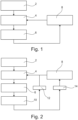
- Figure 1 shows a simple procedure.
- initial damping values for the damping of the prosthetic foot joint are determined. These initial damping values are used to perform at least the first step taken with the prosthetic foot.
- the measured values are recorded using at least one sensor arranged on the prosthetic foot or an element attached thereto.
- These measured values relate, for example, to the course of a force introduction point as a function of the lower leg angle and/or the ankle angle.
- the position of the force introduction point must be recorded several times in succession over at least a portion of the stride.
- the measurement begins at heel strike, and the measurements preferably extend over the entire plantar flexion phase of the stride.
- a comparison step 6 the measured curve of the force application point is compared with a target curve. A gap between the measured curve and the target curve is determined, and the deviation is quantified.
- the damping is adjusted in an adjustment step 8, preferably before the next step begins.
- the next acquisition step 4 is then performed in the next step, and the respective measured values—in this case, the curve of the force application point—are recorded again.
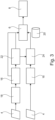
- Figure 2 shows a similar procedure.
- initial damping values for the joint of the prosthetic foot are determined in determination step 2.
- the measured values are recorded in acquisition step 4. These are compared with the corresponding target data in comparison step 6.
- an additional test step 10 checks whether the deviation determined in the comparison step 6, i.e. the distance between the measured values/or the at least one parameter determined therefrom and the stored target values, exceeds a predetermined limit. If this is not the case, If this is the case, no damping adjustment is made along the "No" path 12. The deviation is too small. Instead, a detection step 4 is performed again in the next step that the wearer performs with the prosthetic foot.
- the system proceeds along the "Yes" path 14 to adjustment step 8, so that the damping of the joint is adjusted.
- Figure 3 shows a more detailed description of the process.
- the definition step 2 has been omitted for clarity.
- measured values are recorded, which are, for example, sensor data.
- Figure 3 Two acquisition steps 4 are shown, which do not necessarily have to be performed both at the same time. They describe different procedures that can be performed alternatively or in addition to each other.
- the measured values acquired from the lower acquisition step 4 are recorded in a recording step 16 over at least part of the stance phase of the step, but preferably over the entire stance phase of the step.
- the measured values resulting from the above acquisition step 4 are converted in a conversion step 18 into at least one parameter based on the measured values.
- the parameter thus determined is then recorded over at least part of the stance phase of the step, but preferably over the entire stance phase of the step. This also constitutes a recording step 16.
- the determined and recorded parameter can be compared directly with target values in comparison step 6, which are provided as reference values from an electronic data memory 20, which is only shown schematically. Subsequently, in adjustment step 8, the damping is adjusted based on this comparison.
- another parameter can be created from the characteristic value curve or the previously calculated parameter. If this is the case, this characteristic value curve is then or parameter in comparison step 6 and, on the basis of this comparison, the damping is adjusted in adjustment step 8.
- the measured values acquired in the lower acquisition step 4, which were recorded in the lower recording step 16 are processed together with the parameters determined in the second conversion step 22, for example, by creating a phase diagram 24. This can then also be compared with target values from the electronic data memory 20 in the comparison step 6.
- Figure 4 shows a schematic of a measured value.
- the position of the force introduction point is plotted on the vertical Y-axis and the foot angle, i.e. the angle between the foot part and the ground on which the wearer of the prosthesis walks, is plotted on the horizontal X-axis.
- a target curve 26 shows the desired course. During a step, the course begins in the lower left quadrant.
- the force introduction point (COP) is in the heel area and begins at heel strike. This is represented by the first pictogram 28. If you follow the target curve as the foot angle increases, you can see that the force introduction point initially remains at the heel before moving upwards in the diagram shown, i.e. towards the forefoot.
- the origin of the diagram represents the point at which the foot rests fully on the ground and the lower leg swings over the foot. This is schematically represented by the second pictogram 30. As the foot angle increases, the force application point continues to move toward the forefoot before remaining in the area of the toes until they lift off the ground. This situation is illustrated in the third pictogram 32.
- the dashed line 36 deviates from the target curve in the other direction.
- the cushioning is too soft, causing the foot to plantarflex too quickly. Therefore, the force application point initially does not move with increasing foot angle. It only moves from the heel toward the forefoot when the foot angle is larger than desired. In this case, the cushioning should be increased.
Landscapes
- Health & Medical Sciences (AREA)
- Transplantation (AREA)
- Heart & Thoracic Surgery (AREA)
- Oral & Maxillofacial Surgery (AREA)
- Engineering & Computer Science (AREA)
- Biomedical Technology (AREA)
- Cardiology (AREA)
- Vascular Medicine (AREA)
- Life Sciences & Earth Sciences (AREA)
- Animal Behavior & Ethology (AREA)
- General Health & Medical Sciences (AREA)
- Public Health (AREA)
- Veterinary Medicine (AREA)
- Orthopedic Medicine & Surgery (AREA)
- Prostheses (AREA)
Description
- Die Erfindung betrifft ein Verfahren zum Steuern eines Prothesenfußes, der ein Fußteil und ein Unterschenkelteil aufweist, die mittels eines Gelenkes miteinander verbunden sind, das eine Plantarflexion und eine Dorsalflexion erlaubt, wobei das Gelenk eine einstellbare Dämpfung aufweist.
- Derartige Prothesenfüße sind aus dem Stand der Technik seit langem bekannt. Das Gelenk, das den Fußteil mit dem Unterschenkelteil verbindet, bildet das Knöchelgelenk des Prothesenfußes. Es handelt sich in der Regel um ein Schwenkgelenk, das eine Verschwenkung des Fußteils relativ zum Unterschenkelteil um eine einzige Schwenkachse erlaubt. Es sind jedoch auch mehrachsige Schwenkgelenke oder andere Anordnungen möglich. Bei Prothesenfüßen der hier beschriebenen Art erlaubt das Gelenk eine Plantarflexion und eine Dorsalflexion. Die Dorsalflexion beschreibt eine Verschwenkung des Fußteils um die Schwenkachse des Gelenkes, bei der der Vorfuß-Bereich, also insbesondere die Zehen, nach oben, also in Richtung des Unterschenkels, bewegt werden. Die Plantarflexion ist die entgegengesetzte Bewegung.
- Das Gelenk ist ein gedämpftes Gelenk. Es muss folglich eine Kraft oder ein Drehmoment ausgeübt werden, um die Dämpfung des Gelenkes zu überwinden und eine Verschwenkung des Fußteils relativ zum Unterschenkelteil zu erreichen. Derartige Änderungen sind in unterschiedlichster Form aus dem Stand der Technik bekannt. Bei einer hydraulischen Dämpfung beispielsweise wird beim Verschwenken des Fußteils relativ zum Unterschenkelteil eine Hydraulikflüssigkeit aus einem ersten Zylinder in einem zweiten Zylinder gedrückt. Dies geschieht durch eine Fluidverbindung, in der sich beispielsweise ein Drosselventil befindet. Dieses Ventil kann verstellt werden, wodurch ein schnellerer oder langsamerer Fluss durch die Fluidverbindung erreicht wird. Dadurch wird es vereinfacht oder erschwert, die beiden durch das Gelenk miteinander verbundenen Bauteile relativ zueinander zu verschwenken. Dadurch wird die Dämpfung eingestellt.
- Die hier beschriebenen Gelenke verfügen vorzugsweise nicht über einen Antrieb, durch den beispielsweise das Fußteil relativ zu dem Unterschenkelteil verschwenkt werden kann. Diese Gelenke werden passive Gelenke genannt. Ein angetriebenes, also aktives Gelenk ist aus der
US 10,314,723 B2 - Die
DE 603 09 685 T2 , die den Oberbegriff des Anspruchs 1 offenbart, und dieUS 2002/0138153 A1 beschreiben gedämpfte Gelenke von orthopädietechnischen Einrichtungen, die magnetorheologisches System zum Dämpfen aufweisen. DieDE 20 2016 107 294 U1 beschreibt hingegen ein hydraulisches System. - Bei einem Prothesenfuß der hier beschriebenen Art kann das Unterschenkelteil sehr kurz ausgebildet sein. Es beinhaltet in diesem Fall insbesondere ein Anschlussstück, beispielsweise einen Pyramiden-Adapter, an dem ein Unterschenkelrohr oder eine sonstige Form eines künstlichen Unterschenkels angeordnet sein kann. Alternativ dazu kann das Unterschenkelteil auch länger ausgebildet sein und einstückig mit dem Unterschenkelrohr oder zumindest einem Teil eines Unterschenkelrohres ausgebildet sein. An dem dem Gelenk abgewandten Ende dieses Unterschenkel befindet sich dann ein weiteres Anschlussstück, beispielsweise einen Pyramiden-Adapter, an dem ein weiteres Prothesenelement, beispielsweise ein Unterschenkelrohr oder ein Prothesenknie-Gelenk angeordnet sein kann.
- Es hat sich herausgestellt, dass es von Vorteil ist, die Dämpfung einzustellen, wenn beispielsweise der Träger des Prothesenfußes die Schuhe wechselt. Bei einem harten Schuh, der beispielsweise eine feste Ledersohle aufweist, ist eine weniger starke Dämpfung des Gelenks des Prothesenfußes notwendig, als bei einem sehr weichen Schuh, beispielsweise einem Laufschuh, einem Sportschuh oder einem Hausschuh. Aus dem Stand der Technik sind daher Prothesenfüße bekannt, die über eine Einstell-Einrichtung verfügen, durch die der Träger des Prothesenfu-βes selbstständig den Grad der Dämpfung des Prothesenfußes einstellen kann. Nachteilig ist jedoch, dass der Träger nur nach seinem Gefühl und Empfinden den Grad der Dämpfung einstellen kann und einer Reproduzierbarkeit der eingestellten Dämpfung für unterschiedliche Schuhe nicht gegeben ist. Insbesondere ist es nicht möglich, für unterschiedliche Schuhe die unterschiedlichen Dämpfungsgrade zu speichern.
- Zudem sind Prothesenfüße bekannt, bei denen über Sensoren festgestellt wird, ob der Träger des Prothesenfußes bergauf oder bergab geht. In diesem Fall kann die Dämpfung automatisch angepasst werden, wobei auf dem Weg bergab die Dämpfung in Dorsalflexion-Richtung und beim Weg bergauf in Plantarflexion-Richtung erhöht wird. Nachteilig ist jedoch, dass dies für unterschiedliche Schuhe nicht möglich ist.
- Eine aus dem Stand der Technik bekannte alternative Ausführungsform sieht vor, dass ein Dämpfungselement, das das Gelenk dämpft, ausgetauscht wird, wenn der Benutzer des Prothesenfußes den Schuh wechselt. Dies ist aufwendig und setzt voraus, dass der Benutzer die jeweils nötigen Dämpfungselemente bei sich führt.
- Der Erfindung liegt daher die Aufgabe zugrunde, ein Verfahren zum Steuern des Prothesenfußes vorzuschlagen, bei dem auf unterschiedliche Schuhe mit gegebenenfalls unterschiedlichen Absatzhöhen sowie auf unterschiedliche Bewegungszustände reagiert werden kann, ohne dass der Träger des Prothesenfußes Bauteile auswechseln oder selbstständig Einstellungen vornehmen muss.
- Die Erfindung löst die gestellte Aufgabe durch ein Verfahren zum Steuern eines Prothesenfußes der oben beschriebenen Art, dass die folgenden Schritte aufweist:
- a) Erfassen von Messwerten, die Aussagen über ein Überrollverhalten des Prothesenfußes erlauben, mittels wenigstens eines Sensors,
- b) Vergleichen der erfassten Messwerte und/oder wenigstens eines daraus bestimmten Parameters mit hinterlegten Sollwerten und
- c) Anpassen der Dämpfung in Abhängigkeit des Vergleiches,
- Das Überrollverhalten eines Prothesenfußes beschreibt, wie sich die Parameter des Prothesenfußes, durch die sich die Bewegung des Prothesenfußes beschreiben lässt, während des Überrollens, also während der Standphase eines Gangzyklus, in der der Prothesenfuß Kontakt mit dem Boden hat, verhalten. Diese Parameter können direkt messbare Messgrößen, beispielsweise ein Drehmoment, eine Kraft oder ein Winkel sein. Alternativ oder zusätzlich dazu können diese Parameter auch aus den Messgrößen bestimmbar sein.
- Der Erfindung liegt die Erkenntnis zugrunde, dass ein gesunder Fuß sein eigenes Überrollverhalten sehr schnell so anpasst, dass das Überrollverhalten des Systems aus Fuß und Schuh nahezu konstant ist. Der Fuß gleicht die unterschiedlichen Überrollverhalten, die beispielsweise durch die unterschiedlich harten und unterschiedlich flexiblen Schuhe und Sohlen hervorgerufen werden, aus. Es ist somit nicht notwendig, eine Vielzahl unterschiedlicher Sollwerte desgleichen Messwertes oder Parameters zu hinterlegen, um für jeden Schuh, jede Absatz Höhe und jedes Bewegungsmuster passende Sollwerte bereitstellen zu können. Vielmehr sind die Sollwerte nahezu universell für alle Schuhe und Absatzhöhen sowie zumindest anteilig auch für unterschiedliche Bewegungsmuster verwendbar. Dabei ist selbstverständlich darauf zu achten, dass die jeweils ausgewählten Messwerte, die der wenigstens eine Sensor erfasst, und/oder der wenigstens eine daraus bestimmten Parameter, mit den hinterlegten Sollwerten vergleichbar sind. Die Sollwerte sind folglich Sollwerte für die jeweiligen Messwerte und/oder den wenigstens einen daraus bestimmten Parameter.
- Erfindungsgemäß werden folglich derartige Messwerte, die Aussagen über dieses Überrollverhalten erlauben, mittels wenigstens eines Messwertes erfasst. Sie werden dann beispielsweise mit Sollwerten für diese erfassten Messwerte verglichen. Alternativ oder zusätzlich dazu werden aus den Messwerten ein oder mehrere Parameter bestimmt, die den mit Sollwerten für diesen wenigstens einen Parameter verglichen werden. In Abhängigkeit des Vergleiches wird die Dämpfung angepasst. Je nach Ergebnis des ausgeführten Vergleiches kann eine starke Anpassung, eine schwache Anpassung oder keine Anpassung vorgenommen werden.
- Vorzugsweise wird die Dämpfung nur angepasst, wenn die Messwerte und/oder der wenigstens eine daraus bestimmten Parameter einen vorbestimmten Abstand von den Sollwerten überschreiten.
- Bei dem Vergleich wird ein Abstand der Messwerte und/oder des wenigstens einen Parameters von diesem Sollwert ermittelt. Dies kann beispielsweise eine Differenz, ein Verhältnis, eine Standardabweichung oder eine sonstige Abweichung sein. Zuvor ist ein vorbestimmter Grenzwert, der sogenannte vorbestimmte Abstand, ermittelt und ebenfalls hinterlegt worden. Der ermittelte Abstand, der bei dem Vergleich zwischen Messwert und/oder Parameter mit dem Sollwert ermittelt wurde, wird nun mit dem vorbestimmten Abstand verglichen. Ist der ermittelte Abstand größer, kann die Dämpfung angepasst werden, wobei sich beispielsweise aus dem Vorzeichen des Abstandes bestimmt, ob die Dämpfung erhöht oder abgesenkt werden muss.
- Erfindungsgemäß werden die Messwerte mehrfach während des Schrittzyklus erfasst. Da sie Aussagen über das Überrollverhalten, also das Verhalten von Parametern oder Messgrößen des Prothesenfußes über den Verlauf zumindest eines Teiles eines Schrittzyklus, bevorzugt über die Standphase, besonders bevorzugt über den gesamten Schrittzyklus, treffen sollen, ist es von Vorteil, den zeitlichen Verlauf der Messwerte über zumindest einen Teil des Schrittzyklusses, bevorzugt die Standphase, besonders bevorzugt den gesamten Schrittzyklus zu bestimmen. Sind die Messwerte selbst nicht mit Sollwerten zu vergleichen, muss aus den Messwerten und/oder dem zeitlichen Verlauf der Messwerte der jeweilige wenigstens eine Parameter und/oder dessen zeitlicher Verlauf ermittelt werden. Dabei kann es von Vorteil sein, zunächst den zeitlichen Verlauf der Messwerte zu ermitteln und aus diesem direkt den zeitlichen Verlauf des Parameters zu bestimmen. Alternativ dazu kann es von Vorteil sein, zu jedem Messzeitpunkt aus dem jeweiligen Messwert den wenigstens einen Parameter zu ermitteln und anschließend den zeitlichen Verlauf des Parameters zu bestimmen.
- Bevorzugt wird die Plantardämpfung, also die einer Plantarflexion entgegenwirkende Dämpfung eingestellt. Dabei wird bevorzugt der Verlauf der Plantarflexion über den Knöchelwinkel und/oder den Unterschenkelwinkel angepasst. Der Knöchelwinkel ist der Winkel zwischen dem Unterschenkel und dem Fuß. Der Unterschenkelwinkel ist der Absolutwinkel des Unterschenkels, also beispielsweise der Winkel zwischen dem Unterschenkel und der Vertikalen. Die Vertikale ist die Richtung, in die das Schwerefeld der Erde wirkt. Bevorzugt wird der Verlauf zu Beginn des Fersenauftrittes, besonders bevorzugt vor Beginn des Fersenauftrittes angepasst. Eine weitere Einstellung im Verlauf des Schrittes wird bevorzugt nicht vorgenommen.
- In einer Ausgestaltung des Verfahrens ist die angepasste Dämpfung beim Fersenauftritt, dem sogenannten heel-strike, vorhanden. Da dies der erste Teil der Standphase in einem Schrittzyklus ist, werden die Messwerte und/oder der wenigstens eine daraus bestimmte Parameter des vorangegangenen Schrittes verwendet. Vorzugsweise wird die Dämpfung während des weiteren Verlaufes der Standphase nicht erneut verändert oder angepasst oder wird auf der Grundlage der Messwerte und/oder des wenigstens einen daraus bestimmten Parameter des vorangegangenen Schrittes gesteuert und eingestellt. Dadurch wird der benötigte Rechenaufwand reduziert und das Verfahren energiesparend durchführbar. Es ist in einigen Ausgestaltungen des Verfahrens von Vorteil, wenn weitere Anpassungen während eines Schrittes erfolgen. Dies kann beispielsweise in einer Echtzeitsteuerung erfolgen.
- Vorzugsweise beinhalten die Messwerte eine vertikale Kraft und ein Drehmoment am Gelenk, wobei aus den Messwerten vorzugsweise ein Krafteinleitungspunkt, besonders bevorzugt ein zeitlicher Verlauf des Krafteinleitungspunktes bestimmt wird. In der Standphase eines Schrittzyklus hat der Prothesenfuß Kontakt zum Boden. Dies beginnt mit dem Fersenauftritt. Von diesem Moment an nimmt zunächst die Belastung des Fußes und damit auch eine vertikale Kraft zu. Eine vertikale Kraft wirkt in der Richtung, in der auch die Gewichtskraft wirkt. Gleichzeitig wirkt auf das Gelenk des Prothesenfußes ein Drehmoment, und der Fuß führt eine Plantarflexion durch. Die Kontaktfläche zum Boden nimmt zu bis zu dem Moment, an dem der Fuß vollflächig aufliegt. Dabei kommt es zu einer Dorsalflexion, während der Unterschenkel relativ zum Fuß verschwenkt wird. Der Oberkörper bewegt sich weiter nach vorn. Auch wenn der Fuß in diesem Zeitraum vollflächig am Fußboden aufliegt wandert der Krafteinleitungspunkt weiter nach vorn. Die vertikale Kraft bleibt konstant, da der Fuß voll belastet ist und sich der andere Fuß in der Schwungphase befindet, während der er keinen Kontakt zum Boden hat. Es wirkt ein Drehmoment auf das Gelenk, dass eine Dorsalflexion hervorruft. Am Ende einer Standphase drückt der Fuß den Körper nach vorn, sodass die vertikale Kraft zunimmt und ein Drehmoment auf das Gelenk wirkt, dass erneut eine Plantarflexion bewirkt. Dieser Ablauf ist nahezu unabhängig von der Wahl des Schuhwerkes und der Bewegungsrichtung, beispielsweise auf einer Schräge bergauf oder bergab oder entlang einer Ebene. Die Stärke des Drehmoments und der vertikalen Kraft und insbesondere die Geschwindigkeit, mit der der Krafteinleitungspunkt nach vorn wandert hängt jedoch stark von diesen Parametern ab. Um für den Träger des Prothesenfußes und eine natürlich wirkende Bewegung zu gewährleisten wird die Dämpfung entsprechend angepasst.
- Alternativ oder zusätzlich dazu wird der Krafteinleitungspunkt und/oder dessen zeitlicher Verlauf direkt gemessen und die Messwerte enthalten ihm. Dies kann beispielsweise erreicht werden, wenn der wenigstens eine Sensor eine Mehrzahl von Drucksensoren aufweist, die an einer Sohle des Fußteils angeordnet sind. Besonders bevorzugt handelt es sich um eine drucksensible Schicht, die an der Sohle des Fußteils angeordnet ist. Die Mehrzahl von Drucksensoren oder die drucksensible Schicht ist in der Lage, an unterschiedlichen Positionen an der Sohle des Fußteils den wirkenden Druck und damit die vertikale Kraft zu bestimmen. Da dies in einer Verteilung über die Sohle des Fußteils geschieht, braucht der Krafteinleitungspunkt nicht aufwendig aus den Messwerten bestimmt zu werden, sondern kann nahezu direkt aus den Messwerten abgelesen werden. Geschieht dies mehrfach während eines Gangzyklus kann der zeitliche Verlauf, also die Position des Krafteinleitungspunktes als Funktion der Zeit, bestimmt und gespeichert werden.
- Unabhängig davon, wie der Krafteinleitungspunkt oder der zeitliche Verlauf des Krafteinleitungspunktes bestimmt wird, ist es von Vorteil, den zeitlichen Verlauf des Krafteinleitungspunktes durch einen Kreisabschnitt mit einem Mittelpunkt und einem Radius anzunähern. Bevorzugt werden dieser Mittelpunkt und Radius mit entsprechenden hinterlegten Sollwerten für Mittelpunkt und Radius verglichen. Das Annähern des zeitlichen Verlaufs des Krafteinleitungspunktes durch einen Kreisabschnitt kann durch nahezu alle bekannten fit-Verfahren, bei denen Messwerte mit einer Kurve gefittet werden, geschehen.
- Herkömmlicherweise beträgt der Abstand zwischen dem Krafteinleitungspunkt und der Rotationsachse des Knöchelgelenkes ca. 0 bis 7 cm im Fersenbereich. Im Vorfußbereich liegt er zwischen 0 und 15 cm. Der Unterschenkelwinkel, also der absolut Winkel des Unterschenkels gegen die Vertikale, variiert zwischen -30 ° und +40 °, wobei 0° die Vertikale bezeichnet. Legt man dem optimalen Verlauf des Krafteinleitungspunkt einen Kreisabschnitt zugrunde, ergibt sich ein Radius von etwa 0,5 m.
- Alternativ oder zusätzlich dazu beinhalten die Messwerte einen Unterschenkelwinkel und einen Fußwinkel, bevorzugt deren zeitlichen Verläufe. Besonders bevorzugt wird ein Verhältnis aus Unterschenkelwinkel und Fußwinkel und/oder dessen zeitlicher Verlauf bestimmt. Auch in dieser Ausgestaltung liegt der Erfindung die Erkenntnis zugrunde, das beispielsweise das Verhältnis aus Unterschenkelwinkel und Fußwinkel im zeitlichen Verlauf der Standphase des Gangzyklus nahezu unabhängig von der Wahl des Schuhwerkes und dessen Absatzhöhe ist. Der Fußwinkel und der Unterschenkelwinkel können dabei beispielsweise durch sogenannte Inertialsensoren bestimmt werden, die in der Lage sind, den Winkel gegen die Vertikale oder die Horizontale zu bestimmen. Die Vertikale ist dabei die Richtung, in der die Gravitation und die Gewichtskraft wirkt, während die Horizontale senkrecht auf der Vertikalen steht. Verändert sich das Verhältnis aus Unterschenkelwinkel und Fußwinkel beispielsweise zu schnell, kann die Dämpfung erhöht werden, um eine Änderung des Fußwinkel, die im Wesentlichen durch Verschwenken des Fußteils relativ zum Unterschenkelteil erzeugt wird, zu bremsen.
- Vorzugsweise wird der Vergleich und gegebenenfalls die Anpassung der Dämpfung mehrfach, bevorzugt zeitlich äquidistant, während eines Teiles eines Schrittzyklus, bevorzugt über den ganzen Schrittzyklus, ausgeführt. Zu mehreren Zeitpunkten insbesondere während der Standphase wird folglich der Vergleich zwischen den Messdaten und/oder dem wenigstens einen aus ihnen bestimmten Parameter und den hinterlegten Sollwerten durchgeführt. Immer wenn bei diesem Vergleich der Abstand zwischen den Messwerten und/oder dem bestimmten Parameter und den hinterlegten Sollwerten größer als ein vorbestimmter Abstand ist, wird die Dämpfung angepasst. Auch dies kann, sofern notwendig, mehrfach während eines Schrittzyklus, bevorzugt mehrfach während der Standphase geschehen.
- Vorzugsweise handelt es sich bei der Dämpfung um eine hydraulische und/oder eine magnetorheologische Dämpfung. Beide haben den Vorteil, dass sie sehr schnell einstellbar sind, da zur Anpassung der Dämpfung wenig oder bei der magnetorheologischen Dämpfung keine beweglichen Teile notwendig sind. Eine hydraulische Dämpfung kann die bereits beschriebene Ausführungsform sein, bei der beim Verschwenken des Fußteils relativ zum Unterschenkelteil eine Hydraulikflüssigkeit von einem Volumen in ein anderes Volumen verschoben wird. Dies geschieht durch eine Flüssigkeitsleitung oder Fluid-Verbindung, in der beispielsweise ein Drosselventil enthalten ist. Soll die Dämpfung erhöht werden, wird das Drosselventil weiter geschlossen, sodass der Strömungswiderstand in der Fluid-Verbindung erhöht wird. Sollte Dämpfung verringert werden, wird das Ventil weiter geöffnet, sodass der Strömungswiderstand verringert wird.
- Bei einer magnetorheologischen Dämpfung wird eine Flüssigkeit oder ein Arbeitsmedium verwendet, dessen Fließfähigkeit, Viskosität und/oder Elastizität durch ein Magnetfeld beeinflussbar ist. Soll in diesem Fall beispielsweise die Dämpfung erhöht werden, wird ein Magnetfeld verstärkt, dem die magnetorheologische Flüssigkeit ausgesetzt ist. Dadurch wird die Viskosität verringert und somit eine Strömungswiderstand, der der Flüssigkeit entgegengesetzt wird, erhöht.
- Vorzugsweise verfügt der Fußteil über wenigstens ein Federelement, dessen Federsteifigkeit angepasst wird, wenn die Messwerte einen vorbestimmten Abstand von den Sollwerten überschreiten. Dies ist eine zweite Möglichkeit, dass Überrollverhalten des Prothesenfußes zu modifizieren und an das gewünschte Verhalten anzupassen.
- Die Erfindung löst die gestellte Aufgabe zudem durch einen Prothesenfuß mit einem Fußteil und einem Unterschenkelteil, die mittels eines Gelenkes miteinander verbunden sind, das eine Plantarflexion und eine Dorsalflexion erlaubt, wobei das Gelenk eine einstellbare Dämpfung auszeichnet. Der Prothesenfuß zeichnet sich dadurch aus, dass er über eine elektronische Datenverarbeitungseinrichtung verfügt, die eingerichtet ist zum Durchführen eines hier beschriebenen Verfahrens. Vorzugsweise verfügt der Prothesenfuß über einen elektronischen Datenspeicher, indem die Sollwerte hinterlegt sind. Über wenigstens einen Sensor, der Teil des Prothesenfußes sein kann, dies jedoch nicht muss, werden Messwerte erfasst, die an die elektronische Datenverarbeitungseinrichtung übermittelt werden. Diese vergleicht sie Messwerte entweder mit im elektronischen Datenspeicher hinterlegten Sollwerten oder ermittelt aus den Messwerten den zeitlichen Verlauf der Messwerte oder wenigstens einen Parameter oder dessen zeitlichen Verlauf.
- Mithilfe der beiliegenden Figuren werden nachfolgend einige Ausführungsbeispiele der vorliegenden Erfindung näher erläutert. Es zeigen
- Figuren 1 bis 3 -
- schematische Darstellungen von Verfahrensabläufe gemäß unterschiedlicher Ausführungsbeispiele der vorliegenden Erfindung und
- Figur 4 -
- den Verlauf eines beispielhaften Messwertes.
-
Figur 1 zeigt einen einfachen Verfahrensablauf. Zunächst werden in einem Festlegungsschritt 2 initiale Dämpfungswerte für die Dämpfung des Gelenkes des Prothesenfußes festgelegt. Mit diesen initialen Dämpfungswerten wird zumindest der erste Schritt, der mit dem Prothesenfuß zurückgelegt wird, durchgeführt. - In einem Erfassungsschritt 4 werden die Messwerte mittels des wenigstens einen Sensors, der an dem Prothesenfuß oder einem daran befestigten Element angeordnet ist, erfasst. Diese Messwerte betreffen beispielsweise den Verlauf eines Krafteinleitungspunktes als Funktion des Unterschenkelwinkels und/oder des Knöchelwinkels. Um den Verlauf bestimmen zu können, muss die Position des Krafteinleitungspunktes mehrfach nacheinander zumindest über einen Abschnitt des Schrittes erfasst werden. Vorzugsweise wird mit der Messung beim Fersenauftritt begonnen und die Messungen erstrecken sich vorzugsweise über die gesamte Plantarflexionsphase des Schrittes.
- In einem Vergleichsschritt 6 wird der so gemessene Verlauf des Krafteinleitungspunktes mit einem Soll-Verlauf verglichen. Es wird dabei ein Abstand zwischen dem gemessenen Verlauf und dem Soll-Verlauf festgestellt und die Abweichung quantifiziert.
- Auf der Basis dieses Abstandes wird in einem Anpassungsschritt 8 die Dämpfung angepasst, vorzugsweise bevor der nächste Schritt begonnen wird. Danach wird im nächsten Schritt der nächste Erfassungsschritt 4 durchgeführt und erneut die jeweiligen Messwerte, vorliegend also der Verlauf des Krafteinleitungspunktes erfasst.
-
Figur 2 zeigt ein ähnliches Verfahren. Auch hier werden im Festlegungsschritt 2 initiale Dämpfungswerte für das Gelenk des Prothesenfußes festgelegt. Anschließend werden im Erfassungsschritt 4 die Messwerte erfasst. Diese werden im Vergleichsschritt 6 mit entsprechenden Soll-Daten verglichen. Anders als im inFigur 1 gezeigten Ausführungsbeispiel wird in einem zusätzlichen Prüfschritt 10 geprüft, ob die im Vergleichsschritt 6 ermittelte Abweichung, also der Abstand der Messwerte/oder des wenigstens einen daraus bestimmten Parameters von den hinterlegten Soll-Werten, einen vorbestimmten Grenzwert überschreitet. Ist dies nicht der Fall, wird entlang des "Nein"-Pfades 12 keine Anpassung der Dämpfung vorgenommen. Die Abweichung ist zu klein. Stattdessen wird im nächsten Schritt, den der Träger mit dem Prothesenfuß durchführt, erneut ein Erfassungsschritt 4 durchgeführt. - Ist hingegen der bestimmte Abstand größer als der vorbestimmte Grenzwert wird entlang des "Ja"-Pfades 14 zum Anpassungsschritt 8 übergeleitet, sodass die Dämpfung des Gelenkes angepasst wird.
-
Figur 3 zeigt eine detailliertere Darstellung des Verfahrens. Der Festlegungsschritt 2 ist aus Übersichtlichkeitsgründen weggelassen worden. Im Erfassungsschritt 4 werden Messwerte erfasst, die beispielsweise Sensordaten sind. InFigur 3 sind zwei Erfassungsschritte 4 dargestellt, die nicht zwangsläufig beide durchgeführt werden müssen. Sie beschreiben unterschiedliche Verfahren, die alternativ oder zusätzlich zueinander durchgeführt werden können. Die aus dem unteren Erfassungsschritt 4 erfassten Messwerte werden in einem Aufzeichnungsschritt 16 über zumindest einen Teil der Standphase des Schrittes, vorzugsweise jedoch über die gesamte Standphase des Schrittes aufgezeichnet. - Die aus dem oberen Erfassungsschritt 4 entstehenden Messwerte werden in einem Umrechnungsschritt 18 in wenigstens einen Parameter umgerechnet, der auf den Messwerten basiert. Im nächsten Verfahrensschritt wird dann der so ermittelte Parameter über zumindest einen Teil der Standphase des Schrittes, vorzugsweise jedoch über die gesamte Standphase des Schrittes aufgezeichnet. Auch hierbei handelt es sich folglich um einen Aufzeichnungsschritt 16.
- Nach diesem Aufzeichnungsschritt 16 kann der ermittelte und aufgezeichnete Parameter im Vergleichsschritt 6 direkt mit Soll-Werten verglichen werden, die als Referenz-Werte aus einem elektronischen Datenspeicher 20, der nur schematisch dargestellt ist, bereitgestellt werden. Anschließend erfolgt im Anpassungsschritt 8 die auf der Basis dieses Vergleiches vorzunehmende Anpassung der Dämpfung. Alternativ dazu kann in einem zweiten Umrechnungsschritt 22 ein weiterer Parameter aus dem Verlauf des Kennwertes oder des bisher errechneten Parameters erstellt werden. Ist dies der Fall wird anschließend dieser Verlauf des Kennwertes oder Parameters im Vergleichsschritt 6 verglichen und auf der Basis dieses Vergleiches im Anpassungsschritt 8 die Anpassung der Dämpfung vorgenommen.
- In einer bevorzugten Ausgestaltung des Verfahrens werden die aus dem unteren Erfassungsschritt 4 erfassten Messwerte, die im unteren Aufzeichnungsschritt 16 aufgezeichnet wurden, gemeinsam mit den aus dem zweiten Umrechnungsschritt 22 bestimmten Parametern aufbereitet, indem beispielsweise ein Phasendiagramm 24 erstellt wird. Auch dieses kann dann im Vergleichsschritt 6 mit Sollwerten aus dem elektronischen Datenspeicher 20 verglichen werden.
-
Figur 4 zeigt schematisch einen Verlauf eines Messwertes. Aufgetragen ist die Position des Krafteinleitungspunktes auf der vertikalen Y-Achse und der Fußwinkel, also der Winkel zwischen dem Fußteil und dem Boden, auf dem der Träger der Prothese geht, auf der horizontalen X-Achse. Eine Soll-Kurve 26 zeigt den gewünschten Verlauf. Während eines Schrittes beginnt der Verlauf im linken unteren Quadrant. Der Krafteinleitungspunkt (COP) ist im Bereich der Ferse und beginnt beim Fersenauftritt. Dies wird durch das erste Piktogramm 28 dargestellt. Verfolgt man die Soll-Kurve zu steigendem Fußwinkel erkennt man, dass der Krafteinleitungspunkt zunächst an der Ferse bleibt, bevor er im gezeigten Diagramm nach oben, also in Richtung auf den Vorfuß, wandert. - Im Ursprung des Diagrammes liegt der Punkt, an dem der Fuß vollständig auf dem Boden aufliegt und der Unterschenkel über den Fuß hinwegschwingt. Dies ist durch das zweite Piktogramm 30 schematisch dargestellt. Der Krafteinleitungspunkt wandert mit steigendem Fußwinkel weiterhin Richtung Vorfuß bevor er im Bereich der Zehen bleibt, bis diese sich vom Boden lösen. Diese Situation ist im dritten Piktogramm 32 dargestellt
- Unterschiedliche gemessene Kurven sind durch die dünn dargestellte durchgezogene Linie 34 und die gestrichelte dargestellte Linie 36 dargestellt. Bei der Linie 34 bewegt sich der Krafteinleitungspunkt früher als bei der Soll-Kurve von der Ferse des Fußes weg, der Fuß plantarflektiert nicht ausreichend. Ein Fersenhebel, der durch den Doppelpfeil 38 dargestellt ist, wird dabei reduziert. Um diese Abweichung von der Soll-Kurve zu beheben, wird die Dämpfung verringert, also der einer Bewegung entgegenstehende Widerstand verkleinert. Damit kann die Linie 34 in Richtung auf die Soll-Kurve bewegt werden. Der Fuß plantarflektiert nun schneller.
- Die gestrichelte Linie 36 weicht in die andere Richtung von der Soll-Kurve ab. Hier ist die Dämpfung zu weich, sodass der Fuß zu schnell plantarflektiert und der Krafteinleitungspunkt daher mit zunehmendem Fußwinkel zunächst nicht wandert und erst bei größerem Fußwinkel als gewünscht von der Ferse in Richtung Vorfuß wandert. In diesem Fall sollte die Dämpfung erhöht werden.
-
- 2
- Festlegungsschritt
- 4
- Erfassungsschritt
- 6
- Vergleichsschritt
- 8
- Anpassungsschritt
- 10
- Prüfschritt
- 12
- "Nein"-Pfad
- 14
- "Ja"-Pfad
- 16
- Aufzeichnungsschritt
- 18
- Umrechnungsschritt
- 20
- elektronischer Datenspeicher
- 22
- zweiter Umrechnungsschritt
- 24
- Phasendiagramm
- 26
- Soll-Kurve
- 28
- erstes Piktogramm
- 30
- zweites Piktogramm
- 32
- drittes Piktogramm
- 34
- durchgezogene Linie
- 36
- gestrichelte Linie
- 38
- Fersenhebel
Claims (12)
- Verfahren zum Steuern eines Prothesenfußes, der ein Fußteil und ein Unterschenkelteil aufweist, die mittels eines Gelenkes miteinander verbunden sind, das eine Plantarflexion und eine Dorsalflexion erlaubt, wobei das Gelenk eine einstellbare Dämpfung aufweist,wobei das Verfahren folgende Schritte aufweist:a) Erfassen von Messwerten, die Aussagen über ein Überrollverhalten des Prothesenfußes erlauben, mittels wenigstens eines Sensors,
gekennzeichnet durchb) Vergleichen der erfassten Messwerte und/oder wenigstens eines daraus bestimmten Parameters mit hinterlegten Sollwerten undc) Anpassen der Dämpfung in Abhängigkeit des Vergleiches,wobei die Messwerte mehrfach während eines Schrittzyklus erfasst werden,wobei ein Verlauf der Messwerte über zumindest einen Teil des Schrittzyklus mit einem Verlauf der hinterlegten Sollwerte verglichen wird. - Verfahren nach Anspruch 1, dadurch gekennzeichnet, dass die Dämpfung nur angepasst wird, wenn die Messwerte und/oder der wenigstens eine daraus bestimmte Parameter einen vorbestimmten Abstand von den Sollwerten überschreiten.
- Verfahren nach Anspruch 1 oder 2, dadurch gekennzeichnet, dass ein Verlauf der Messwerte über den ganzen Schrittzyklus mit einem Verlauf der hinterlegten Sollwerte verglichen wird
- Verfahren nach einem der vorstehenden Ansprüche, dadurch gekennzeichnet, dass ein Verlauf der Plantardämpfung über den Knöchelwinkel und/oder den Unterschenkelwinkel, angepasst wird, wobei der Verlauf vorzugsweise zu Beginn des Fersenauftrittes, besonders bevorzugt vor Beginn des Fersenauftrittes, angepasst wird und im weiteren Verlauf eines Schrittes keine weitere Anpassung des Verlaufes erfolgt.
- Verfahren nach einem der vorstehenden Ansprüche, dadurch gekennzeichnet, dass die Messwerte eine vertikale Kraft und ein Drehmoment am Gelenk beinhalten wobei aus den Messwerten vorzugsweise ein Krafteinleitungspunkt, besonders bevorzugt ein zeitlicher Verlauf des Krafteinleitungspunktes bestimmt wird.
- Verfahren nach einem der vorstehenden Ansprüche, dadurch gekennzeichnet, dass die Messwerte den Krafteinleitungspunkt und/oder dessen zeitlichen Verlauf beinhalten, und der wenigstens eine Sensor eine Mehrzahl von Drucksensoren, bevorzugt eine drucksensible Schicht an einer Unterseite einer Sohle des Fußteils aufweist.
- Verfahren nach Anspruch 5 oder 6, dadurch gekennzeichnet, dass der zeitliche Verlauf des Krafteinleitungspunktes durch einen Kreisabschnitt mit einem Mittelpunkt und Radius angenähert wird, die mit einem hinterlegten Mittelpunkt und/oder Radius verglichen werden.
- Verfahren nach einem der vorstehenden Ansprüche, dadurch gekennzeichnet, dass die Messwerte ein Unterschenkelwinkel und ein Fußwinkel, bevorzugt deren zeitlichen Verläufe sind, wobei besonders bevorzugt ein Verhältnis aus Unterschenkelwinkel und Fußwinkel und/oder dessen zeitlicher Verlauf bestimmt wird.
- Verfahren nach einem der vorstehenden Ansprüche, dadurch gekennzeichnet, dass der Vergleich und gegebenenfalls die Anpassung der Dämpfung mehrfach, bevorzugt zeitlich äquidistant, während eines Teiles eines Schrittzyklus, bevorzugt über den ganzen Schrittzyklus, ausgeführt wird.
- Verfahren nach einem der vorstehenden Ansprüche, dadurch gekennzeichnet, dass des sich bei der Dämpfung um eine hydraulische und/oder eine magnetorheologische Dämpfung handelt.
- Verfahren nach einem der vorstehenden Ansprüche, dadurch gekennzeichnet, dass der Fußteil wenigstens ein Federelement aufweist, dessen Federsteifigkeit angepasst wird, wenn die Messwerte einen vorbestimmten Abstand von den Sollwerten überschreiten.
- Prothesenfuß mit einem Fußteil und einem Unterschenkelteil, die mittels eines Gelenkes miteinander verbunden sind, das eine Plantarflexion und eine Dorsalflexion erlaubt, wobei das Gelenk eine einstellbare Dämpfung aufweist, gekennzeichnet durch eine elektronische Datenverarbeitungseinrichtung, die eingerichtet ist zum Durchführen eines Verfahrens nach einem der vorstehenden Ansprüche.
Applications Claiming Priority (2)
| Application Number | Priority Date | Filing Date | Title |
|---|---|---|---|
| DE102019121595.1A DE102019121595A1 (de) | 2019-08-09 | 2019-08-09 | Verfahren zum Steuern eines Prothesenfußes |
| PCT/EP2020/071712 WO2021028244A1 (de) | 2019-08-09 | 2020-07-31 | Verfahren zum steuern eines prothesenfusses |
Publications (2)
| Publication Number | Publication Date |
|---|---|
| EP4009917A1 EP4009917A1 (de) | 2022-06-15 |
| EP4009917B1 true EP4009917B1 (de) | 2025-04-30 |
Family
ID=71899771
Family Applications (1)
| Application Number | Title | Priority Date | Filing Date |
|---|---|---|---|
| EP20750259.2A Active EP4009917B1 (de) | 2019-08-09 | 2020-07-31 | Verfahren zum steuern eines prothesenfusses |
Country Status (4)
| Country | Link |
|---|---|
| US (1) | US20220287856A1 (de) |
| EP (1) | EP4009917B1 (de) |
| DE (1) | DE102019121595A1 (de) |
| WO (1) | WO2021028244A1 (de) |
Families Citing this family (1)
| Publication number | Priority date | Publication date | Assignee | Title |
|---|---|---|---|---|
| DE102020125256A1 (de) | 2020-09-28 | 2022-03-31 | Otto Bock Healthcare Products Gmbh | Verfahren zur Steuerung eines Prothesenfußes |
Citations (4)
| Publication number | Priority date | Publication date | Assignee | Title |
|---|---|---|---|---|
| DE60309685T2 (de) * | 2002-04-12 | 2007-09-20 | James Jay Norman Martin | Elektronisch gesteuertes prothesensystem |
| EP2087858B1 (de) * | 2008-02-07 | 2015-09-23 | Otto Bock HealthCare GmbH | Passives orthopädisches Hilfsmittel in Form einer Fussprothese oder Fussorthese |
| US20160278947A1 (en) * | 2002-04-12 | 2016-09-29 | James Jay Martin | Electronically controlled prosthetic system |
| DE202016107294U1 (de) * | 2016-12-22 | 2017-01-13 | Otto Bock Healthcare Gmbh | Künstliches Knöchelgelenk |
Family Cites Families (5)
| Publication number | Priority date | Publication date | Assignee | Title |
|---|---|---|---|---|
| US6443993B1 (en) * | 2001-03-23 | 2002-09-03 | Wayne Koniuk | Self-adjusting prosthetic ankle apparatus |
| GB201121437D0 (en) * | 2011-12-13 | 2012-01-25 | Blatchford & Sons Ltd | A lower limb prothesis |
| US10314723B2 (en) * | 2013-05-23 | 2019-06-11 | Rehabilitation Institute Of Chicago | Effective shape controller for lower limb |
| DE102014010938B4 (de) * | 2014-07-28 | 2023-01-12 | Ottobock Se & Co. Kgaa | Prothesenfuß, System aus Prothesenfuß und einem Schuh sowie Verfahren zum Anpassen der Absatzhöhe eines Prothesenfußes |
| DE102017115267A1 (de) * | 2017-07-07 | 2019-01-10 | Ottobock Se & Co. Kgaa | Orthopädietechnische Gelenkeinrichtung |
-
2019
- 2019-08-09 DE DE102019121595.1A patent/DE102019121595A1/de active Pending
-
2020
- 2020-07-31 EP EP20750259.2A patent/EP4009917B1/de active Active
- 2020-07-31 WO PCT/EP2020/071712 patent/WO2021028244A1/de not_active Ceased
- 2020-07-31 US US17/633,531 patent/US20220287856A1/en active Pending
Patent Citations (4)
| Publication number | Priority date | Publication date | Assignee | Title |
|---|---|---|---|---|
| DE60309685T2 (de) * | 2002-04-12 | 2007-09-20 | James Jay Norman Martin | Elektronisch gesteuertes prothesensystem |
| US20160278947A1 (en) * | 2002-04-12 | 2016-09-29 | James Jay Martin | Electronically controlled prosthetic system |
| EP2087858B1 (de) * | 2008-02-07 | 2015-09-23 | Otto Bock HealthCare GmbH | Passives orthopädisches Hilfsmittel in Form einer Fussprothese oder Fussorthese |
| DE202016107294U1 (de) * | 2016-12-22 | 2017-01-13 | Otto Bock Healthcare Gmbh | Künstliches Knöchelgelenk |
Also Published As
| Publication number | Publication date |
|---|---|
| US20220287856A1 (en) | 2022-09-15 |
| DE102019121595A1 (de) | 2021-02-11 |
| WO2021028244A1 (de) | 2021-02-18 |
| EP4009917A1 (de) | 2022-06-15 |
Similar Documents
| Publication | Publication Date | Title |
|---|---|---|
| EP2990014B1 (de) | Passives orthopädisches hilfsmittel in form einer fussprothese oder fussorthese | |
| DE102015106384B4 (de) | Verfahren zur Steuerung einer Dämpfungsveränderung bei einem künstlichen Gelenk | |
| EP2649968B1 (de) | Verfahren zur Steuerung eines orthopädischen Fußteils und das orthopädische Fußteil | |
| DE102013013810B3 (de) | Verfahren zur Steuerung eines künstlichen Orthesen- oder Prothesenkniegelenkes | |
| EP1058524B1 (de) | Beinprothese mit einem künstlichen kniegelenk und verfahren zur steuerung einer beinprothese | |
| EP4216880B1 (de) | Verfahren zur steuerung eines prothesenfusses | |
| DE102020004339B4 (de) | Verfahren zur Steuerung einer Prothese oder Orthese | |
| DE102015106389B4 (de) | Verfahren zur Steuerung eines künstlichen Kniegelenkes | |
| EP3979952A1 (de) | Verfahren zum steuern eines künstlichen kniegelenkes | |
| EP3174505B1 (de) | Prothesenfuss, system aus prothesenfuss und einem schuh sowie verfahren zum anpassen der absatzhöhe eines prothesenfusses | |
| DE102020004338B4 (de) | Verfahren zur Steuerung einer Prothese oder Orthese | |
| DE102019121595A1 (de) | Verfahren zum Steuern eines Prothesenfußes | |
| DE102021006127A1 (de) | Orthopädietechnische Elnrichtung und Verfahren zu deren Steuerung | |
| EP4633545A1 (de) | Orthopädietechnische einrichtung und verfahren zu deren steuerung | |
| EP4601588B1 (de) | Verfahren zum steuern einer unterschenkelprothese und unterschenkelprothese | |
| DE102023108577A1 (de) | Verfahren zur Steuerung einer orthopädietechnischen Gelenkeinrichtung | |
| EP4601587B1 (de) | Verfahren zum steuern einer unterschenkelprothese und unterschenkelprothese |
Legal Events
| Date | Code | Title | Description |
|---|---|---|---|
| STAA | Information on the status of an ep patent application or granted ep patent |
Free format text: STATUS: UNKNOWN |
|
| STAA | Information on the status of an ep patent application or granted ep patent |
Free format text: STATUS: THE INTERNATIONAL PUBLICATION HAS BEEN MADE |
|
| PUAI | Public reference made under article 153(3) epc to a published international application that has entered the european phase |
Free format text: ORIGINAL CODE: 0009012 |
|
| STAA | Information on the status of an ep patent application or granted ep patent |
Free format text: STATUS: REQUEST FOR EXAMINATION WAS MADE |
|
| 17P | Request for examination filed |
Effective date: 20220223 |
|
| AK | Designated contracting states |
Kind code of ref document: A1 Designated state(s): AL AT BE BG CH CY CZ DE DK EE ES FI FR GB GR HR HU IE IS IT LI LT LU LV MC MK MT NL NO PL PT RO RS SE SI SK SM TR |
|
| DAV | Request for validation of the european patent (deleted) | ||
| DAX | Request for extension of the european patent (deleted) | ||
| STAA | Information on the status of an ep patent application or granted ep patent |
Free format text: STATUS: EXAMINATION IS IN PROGRESS |
|
| 17Q | First examination report despatched |
Effective date: 20230313 |
|
| GRAP | Despatch of communication of intention to grant a patent |
Free format text: ORIGINAL CODE: EPIDOSNIGR1 |
|
| STAA | Information on the status of an ep patent application or granted ep patent |
Free format text: STATUS: GRANT OF PATENT IS INTENDED |
|
| INTG | Intention to grant announced |
Effective date: 20241220 |
|
| GRAS | Grant fee paid |
Free format text: ORIGINAL CODE: EPIDOSNIGR3 |
|
| GRAA | (expected) grant |
Free format text: ORIGINAL CODE: 0009210 |
|
| STAA | Information on the status of an ep patent application or granted ep patent |
Free format text: STATUS: THE PATENT HAS BEEN GRANTED |
|
| AK | Designated contracting states |
Kind code of ref document: B1 Designated state(s): AL AT BE BG CH CY CZ DE DK EE ES FI FR GB GR HR HU IE IS IT LI LT LU LV MC MK MT NL NO PL PT RO RS SE SI SK SM TR |
|
| REG | Reference to a national code |
Ref country code: CH Ref legal event code: EP Ref country code: GB Ref legal event code: FG4D Free format text: NOT ENGLISH |
|
| REG | Reference to a national code |
Ref country code: DE Ref legal event code: R096 Ref document number: 502020010962 Country of ref document: DE |
|
| REG | Reference to a national code |
Ref country code: IE Ref legal event code: FG4D Free format text: LANGUAGE OF EP DOCUMENT: GERMAN |
|
| REG | Reference to a national code |
Ref country code: NL Ref legal event code: MP Effective date: 20250430 |
|
| PG25 | Lapsed in a contracting state [announced via postgrant information from national office to epo] |
Ref country code: FI Free format text: LAPSE BECAUSE OF FAILURE TO SUBMIT A TRANSLATION OF THE DESCRIPTION OR TO PAY THE FEE WITHIN THE PRESCRIBED TIME-LIMIT Effective date: 20250430 Ref country code: ES Free format text: LAPSE BECAUSE OF FAILURE TO SUBMIT A TRANSLATION OF THE DESCRIPTION OR TO PAY THE FEE WITHIN THE PRESCRIBED TIME-LIMIT Effective date: 20250430 Ref country code: PT Free format text: LAPSE BECAUSE OF FAILURE TO SUBMIT A TRANSLATION OF THE DESCRIPTION OR TO PAY THE FEE WITHIN THE PRESCRIBED TIME-LIMIT Effective date: 20250901 |
|
| PGFP | Annual fee paid to national office [announced via postgrant information from national office to epo] |
Ref country code: DE Payment date: 20250722 Year of fee payment: 6 |
|
| REG | Reference to a national code |
Ref country code: LT Ref legal event code: MG9D |
|
| PG25 | Lapsed in a contracting state [announced via postgrant information from national office to epo] |
Ref country code: NO Free format text: LAPSE BECAUSE OF FAILURE TO SUBMIT A TRANSLATION OF THE DESCRIPTION OR TO PAY THE FEE WITHIN THE PRESCRIBED TIME-LIMIT Effective date: 20250730 Ref country code: GR Free format text: LAPSE BECAUSE OF FAILURE TO SUBMIT A TRANSLATION OF THE DESCRIPTION OR TO PAY THE FEE WITHIN THE PRESCRIBED TIME-LIMIT Effective date: 20250731 |
|
| PG25 | Lapsed in a contracting state [announced via postgrant information from national office to epo] |
Ref country code: NL Free format text: LAPSE BECAUSE OF FAILURE TO SUBMIT A TRANSLATION OF THE DESCRIPTION OR TO PAY THE FEE WITHIN THE PRESCRIBED TIME-LIMIT Effective date: 20250430 Ref country code: PL Free format text: LAPSE BECAUSE OF FAILURE TO SUBMIT A TRANSLATION OF THE DESCRIPTION OR TO PAY THE FEE WITHIN THE PRESCRIBED TIME-LIMIT Effective date: 20250430 |
|
| PG25 | Lapsed in a contracting state [announced via postgrant information from national office to epo] |
Ref country code: BG Free format text: LAPSE BECAUSE OF FAILURE TO SUBMIT A TRANSLATION OF THE DESCRIPTION OR TO PAY THE FEE WITHIN THE PRESCRIBED TIME-LIMIT Effective date: 20250430 |
|
| PGFP | Annual fee paid to national office [announced via postgrant information from national office to epo] |
Ref country code: GB Payment date: 20250724 Year of fee payment: 6 |
|
| PG25 | Lapsed in a contracting state [announced via postgrant information from national office to epo] |
Ref country code: HR Free format text: LAPSE BECAUSE OF FAILURE TO SUBMIT A TRANSLATION OF THE DESCRIPTION OR TO PAY THE FEE WITHIN THE PRESCRIBED TIME-LIMIT Effective date: 20250430 |
|
| PGFP | Annual fee paid to national office [announced via postgrant information from national office to epo] |
Ref country code: FR Payment date: 20250723 Year of fee payment: 6 |
|
| PG25 | Lapsed in a contracting state [announced via postgrant information from national office to epo] |
Ref country code: RS Free format text: LAPSE BECAUSE OF FAILURE TO SUBMIT A TRANSLATION OF THE DESCRIPTION OR TO PAY THE FEE WITHIN THE PRESCRIBED TIME-LIMIT Effective date: 20250731 |
|
| PG25 | Lapsed in a contracting state [announced via postgrant information from national office to epo] |
Ref country code: IS Free format text: LAPSE BECAUSE OF FAILURE TO SUBMIT A TRANSLATION OF THE DESCRIPTION OR TO PAY THE FEE WITHIN THE PRESCRIBED TIME-LIMIT Effective date: 20250830 |
|
| PG25 | Lapsed in a contracting state [announced via postgrant information from national office to epo] |
Ref country code: LV Free format text: LAPSE BECAUSE OF FAILURE TO SUBMIT A TRANSLATION OF THE DESCRIPTION OR TO PAY THE FEE WITHIN THE PRESCRIBED TIME-LIMIT Effective date: 20250430 |
|
| PG25 | Lapsed in a contracting state [announced via postgrant information from national office to epo] |
Ref country code: DK Free format text: LAPSE BECAUSE OF FAILURE TO SUBMIT A TRANSLATION OF THE DESCRIPTION OR TO PAY THE FEE WITHIN THE PRESCRIBED TIME-LIMIT Effective date: 20250430 Ref country code: SM Free format text: LAPSE BECAUSE OF FAILURE TO SUBMIT A TRANSLATION OF THE DESCRIPTION OR TO PAY THE FEE WITHIN THE PRESCRIBED TIME-LIMIT Effective date: 20250430 |
|
| PG25 | Lapsed in a contracting state [announced via postgrant information from national office to epo] |
Ref country code: CZ Free format text: LAPSE BECAUSE OF FAILURE TO SUBMIT A TRANSLATION OF THE DESCRIPTION OR TO PAY THE FEE WITHIN THE PRESCRIBED TIME-LIMIT Effective date: 20250430 |
|
| PG25 | Lapsed in a contracting state [announced via postgrant information from national office to epo] |
Ref country code: EE Free format text: LAPSE BECAUSE OF FAILURE TO SUBMIT A TRANSLATION OF THE DESCRIPTION OR TO PAY THE FEE WITHIN THE PRESCRIBED TIME-LIMIT Effective date: 20250430 |
|
| PG25 | Lapsed in a contracting state [announced via postgrant information from national office to epo] |
Ref country code: SK Free format text: LAPSE BECAUSE OF FAILURE TO SUBMIT A TRANSLATION OF THE DESCRIPTION OR TO PAY THE FEE WITHIN THE PRESCRIBED TIME-LIMIT Effective date: 20250430 Ref country code: RO Free format text: LAPSE BECAUSE OF FAILURE TO SUBMIT A TRANSLATION OF THE DESCRIPTION OR TO PAY THE FEE WITHIN THE PRESCRIBED TIME-LIMIT Effective date: 20250430 |
|
| PG25 | Lapsed in a contracting state [announced via postgrant information from national office to epo] |
Ref country code: IT Free format text: LAPSE BECAUSE OF FAILURE TO SUBMIT A TRANSLATION OF THE DESCRIPTION OR TO PAY THE FEE WITHIN THE PRESCRIBED TIME-LIMIT Effective date: 20250430 |
|
| REG | Reference to a national code |
Ref country code: DE Ref legal event code: R097 Ref document number: 502020010962 Country of ref document: DE |
|
| REG | Reference to a national code |
Ref country code: CH Ref legal event code: H13 Free format text: ST27 STATUS EVENT CODE: U-0-0-H10-H13 (AS PROVIDED BY THE NATIONAL OFFICE) Effective date: 20260224 |
|
| PLBE | No opposition filed within time limit |
Free format text: ORIGINAL CODE: 0009261 |
|
| STAA | Information on the status of an ep patent application or granted ep patent |
Free format text: STATUS: NO OPPOSITION FILED WITHIN TIME LIMIT |
|
| REG | Reference to a national code |
Ref country code: CH Ref legal event code: L10 Free format text: ST27 STATUS EVENT CODE: U-0-0-L10-L00 (AS PROVIDED BY THE NATIONAL OFFICE) Effective date: 20260311 |
|
| PG25 | Lapsed in a contracting state [announced via postgrant information from national office to epo] |
Ref country code: LU Free format text: LAPSE BECAUSE OF NON-PAYMENT OF DUE FEES Effective date: 20250731 |
|
| REG | Reference to a national code |
Ref country code: BE Ref legal event code: MM Effective date: 20250731 |
|
| 26N | No opposition filed |
Effective date: 20260202 |
|
| PG25 | Lapsed in a contracting state [announced via postgrant information from national office to epo] |
Ref country code: BE Free format text: LAPSE BECAUSE OF NON-PAYMENT OF DUE FEES Effective date: 20250731 |
|
| PG25 | Lapsed in a contracting state [announced via postgrant information from national office to epo] |
Ref country code: CH Free format text: LAPSE BECAUSE OF NON-PAYMENT OF DUE FEES Effective date: 20250731 |