EP4009621A1 - Imaging apparatus and electronic device - Google Patents
Imaging apparatus and electronic device Download PDFInfo
- Publication number
- EP4009621A1 EP4009621A1 EP20849596.0A EP20849596A EP4009621A1 EP 4009621 A1 EP4009621 A1 EP 4009621A1 EP 20849596 A EP20849596 A EP 20849596A EP 4009621 A1 EP4009621 A1 EP 4009621A1
- Authority
- EP
- European Patent Office
- Prior art keywords
- groove
- disposed
- sliding
- side plate
- lens module
- Prior art date
- Legal status (The legal status is an assumption and is not a legal conclusion. Google has not performed a legal analysis and makes no representation as to the accuracy of the status listed.)
- Granted
Links
Images




Classifications
-
- G—PHYSICS
- G02—OPTICS
- G02B—OPTICAL ELEMENTS, SYSTEMS OR APPARATUS
- G02B7/00—Mountings, adjusting means, or light-tight connections, for optical elements
- G02B7/02—Mountings, adjusting means, or light-tight connections, for optical elements for lenses
- G02B7/04—Mountings, adjusting means, or light-tight connections, for optical elements for lenses with mechanism for focusing or varying magnification
-
- G—PHYSICS
- G02—OPTICS
- G02B—OPTICAL ELEMENTS, SYSTEMS OR APPARATUS
- G02B13/00—Optical objectives specially designed for the purposes specified below
- G02B13/001—Miniaturised objectives for electronic devices, e.g. portable telephones, webcams, PDAs, small digital cameras
- G02B13/0055—Miniaturised objectives for electronic devices, e.g. portable telephones, webcams, PDAs, small digital cameras employing a special optical element
- G02B13/0065—Miniaturised objectives for electronic devices, e.g. portable telephones, webcams, PDAs, small digital cameras employing a special optical element having a beam-folding prism or mirror
-
- G—PHYSICS
- G02—OPTICS
- G02B—OPTICAL ELEMENTS, SYSTEMS OR APPARATUS
- G02B7/00—Mountings, adjusting means, or light-tight connections, for optical elements
- G02B7/02—Mountings, adjusting means, or light-tight connections, for optical elements for lenses
- G02B7/021—Mountings, adjusting means, or light-tight connections, for optical elements for lenses for more than one lens
-
- G—PHYSICS
- G02—OPTICS
- G02B—OPTICAL ELEMENTS, SYSTEMS OR APPARATUS
- G02B7/00—Mountings, adjusting means, or light-tight connections, for optical elements
- G02B7/18—Mountings, adjusting means, or light-tight connections, for optical elements for prisms; for mirrors
- G02B7/1805—Mountings, adjusting means, or light-tight connections, for optical elements for prisms; for mirrors for prisms
-
- H—ELECTRICITY
- H04—ELECTRIC COMMUNICATION TECHNIQUE
- H04N—PICTORIAL COMMUNICATION, e.g. TELEVISION
- H04N23/00—Cameras or camera modules comprising electronic image sensors; Control thereof
- H04N23/50—Constructional details
- H04N23/55—Optical parts specially adapted for electronic image sensors; Mounting thereof
Definitions
- the present disclosure relates to the field of consumer electronics technology, and in particular to an imaging device and an electronic device.
- an electronic device such as a mobile phone is generally provided with a separate telephoto lens and a separate wide-angle lens, so that the telephotography and the wide-angle photography are realized by switching the lenses.
- the present disclosure provides an imaging device and an electronic device.
- the imaging device of the present disclosure comprises a housing and a sliding lens assembly.
- the housing comprises a base plate and a side plate disposed on the base plate.
- the side plate is provided with a sliding groove.
- the first lens module comprises a casing and a lens group disposed in the casing.
- the casing comprises a main body and a sliding block coupled to the main body. An extending direction of the sliding groove is parallel to an optical axis of the lens group.
- the sliding block is slidably disposed in the sliding groove. Sliding of the casing drives sliding of the lens group.
- the electronic device of the present disclosure comprises a chassis and an imaging device disposed on the chassis.
- the imaging device of the present disclosure comprises a housing and a sliding lens assembly.
- the housing comprises a base plate and a side plate disposed on the base plate.
- the side plate is provided with a sliding groove.
- the first lens module comprises a casing and a lens group disposed in the casing.
- the casing comprises a main body and a sliding block coupled to the main body. An extending direction of the sliding groove is parallel to an optical axis of the lens group.
- the sliding block is slidably disposed in the sliding groove. Sliding of the casing drives sliding of the lens group.
- the sliding block of the casing cooperates with the sliding groove of the side plate of the housing to move the lens group, so that a focal length of the imaging device is variable. Therefore, telephotography and wide-angle photography can be realized without disposing a telephoto lens and a wide-angle lens at a same time.
- a description that a first feature is "on” or “under” a second feature may indicate that the first feature directly contacts the second feature, or that the first feature and the second feature are indirectly contacted through an intermediary.
- a description that the first feature is "on”, “above”, or “on top of' the second feature may indicate that the first feature is right or obliquely “on”, “above”, or “on top of' the second feature, or just means that a sea-level elevation of the first feature is greater than a sea-level elevation of the second feature.
- a description that the first feature "under”, “below”, or “on bottom of' the second feature may indicate that the first feature is right or obliquely “under”, “below”, or “on bottom of' the second feature, or just means that the sea-level elevation of the first feature is less than the sea-level elevation of the second feature.
- an imaging device 100 comprises a housing 10 and a first lens module 20.
- the housing 10 comprises a base plate 11 and a side plate 12 disposed on the base plate 11.
- the side plate 12 is provided with a sliding groove 125.
- the first lens module 20 comprises a casing 21 and a lens group 22 disposed in the casing 21.
- the casing 21 comprises a main body 211 and a sliding block 212 connected to the main body 211.
- An extending direction of the sliding groove 125 is parallel to an optical axis O of the lens group 22.
- the sliding block 212 is slidably disposed in the sliding groove 125. Sliding of the casing 21 drives sliding of the lens group 22.
- opposite sides of the sliding block 212 respectively abut against opposite sides of an inner wall of the sliding groove 125.
- the side plate 12 is further provided with an installation groove 126.
- One end of the installation groove 126 penetrates a surface of the side plate 12 away from the base plate 11, and the other end of the installation groove 126 communicates with the sliding groove 125.
- the sliding block 212 is disposed in the sliding groove 125 through the installation groove 126.
- an extending direction of the installation groove 126 is perpendicular or inclined to the extending direction of the sliding groove 125.
- the housing 10 further comprises a cover plate 13 disposed on the side plate 12 and comprising a cover plate body 131 and a resisting portion 132.
- the resisting portion 132 is disposed on both sides of the cover plate body 131 and in the installation groove 126.
- a length of the resisting portion 132 in a direction perpendicular to the bearing surface 111 of the base plate 11 is equal to a depth of the installation groove 126 in the direction perpendicular to the bearing surface 111.
- the resisting portion 132 when the resisting portion 132 is disposed in the installation groove 126, the resisting portion 132 completely fills the installation groove 126.
- the casing 21 further comprises a top surface 213 and a bottom surface 214 opposite to each other.
- the top surface 213 faces the cover plate 13.
- the bottom surface 214 faces the base plate 11 and is provided with a first groove 215.
- a surface of the base plate 11 facing the bottom surface 214 is provided with a first slide rail 112.
- the first lens module 20 further comprises a first rolling ball 23 disposed in the first groove 215 and abuts against a bottom of the first slide rail 112.
- the top surface 213 is provided with a second groove 216.
- the first lens module 20 further comprises a second rolling ball 24 disposed in the second groove 216 and abuts against the cover plate 13.
- a surface of the cover plate 13 facing the top surface 213 is provided with a second slide rail 134.
- the second rolling ball 24 is disposed in the second groove 216 and abuts against a bottom of the second slide rail 134.
- a number of the first lens module 20 may be multiple.
- the sliding block 212 of each first lens module 20 is slidably disposed in the sliding groove 125.
- the housing 10 further comprises one or more spacer plates 15 connected to the side plate 12. Two adjacent first lens modules 20 are separated by one spacer plate 15.
- An electronic device 1000 of the present disclosure comprises a chassis 200 and an imaging device 100 combined with the chassis 200.
- the imaging device 100 comprises a housing 10 and a first lens module 20.
- the housing 10 comprises a base plate 11 and a side plate 12 disposed on the base plate 11.
- the side plate 12 is provided with a sliding groove 125.
- the first lens module 20 comprises a casing 21 and a lens group 22 disposed in the casing 21.
- the casing 21 comprises a main body 211 and a sliding block 212 connected to the main body 211.
- An extending direction of the sliding groove 125 is parallel to an optical axis O of the lens group 22.
- the sliding block 212 is slidably disposed in the sliding groove 125. Sliding of the casing 21 drives sliding of the lens group 22.
- opposite sides of the sliding block 212 respectively abut against opposite sides of an inner wall of the sliding groove 125.
- the side plate 12 is further provided with an installation groove 126.
- One end of the installation groove 126 penetrates a surface of the side plate 12 away from the base plate 11, and the other end of the installation groove 126 communicates with the sliding groove 125.
- the sliding block 212 is disposed in the sliding groove 125 through the installation groove 126.
- an extending direction of the installation groove 126 is perpendicular or inclined to the extending direction of the sliding groove 125.
- the housing 10 further comprises a cover plate 13 disposed on the side plate 12 and comprising a cover plate body 131 and a resisting portion 132.
- the resisting portion 132 is disposed on both sides of the cover plate body 131 and in the installation groove 126.
- a length of the resisting portion 132 in a direction perpendicular to the bearing surface 111 of the base plate 11 is equal to a depth of the installation groove 126 in the direction perpendicular to the bearing surface 111.
- the resisting portion 132 when the resisting portion 132 is disposed in the installation groove 126, the resisting portion 132 completely fills the installation groove 126.
- the casing 21 further comprises a top surface 213 and a bottom surface 214 opposite to each other.
- the top surface 213 faces the cover plate 13.
- the bottom surface 214 faces the base plate 11 and is provided with a first groove 215.
- a surface of the base plate 11 facing the bottom surface 214 is provided with a first slide rail 112.
- the first lens module 20 further comprises a first rolling ball 23 disposed in the first groove 215 and abuts against a bottom of the first slide rail 112.
- the top surface 213 is provided with a second groove 216.
- the first lens module 20 further comprises a second rolling ball 24 disposed in the second groove 216 and abuts against the cover plate 13.
- a surface of the cover plate 13 facing the top surface 213 is provided with a second slide rail 134.
- the second rolling ball 24 is disposed in the second groove 216 and abuts against a bottom of the second slide rail 134.
- a number of the first lens module 20 may be multiple.
- the sliding block 212 of each first lens module 20 is slidably disposed in the sliding groove 125.
- the housing 10 further comprises one or more spacer plates 15 connected to the side plate 12. Two adjacent first lens modules 20 are separated by one spacer plate 15.
- the electronic device 1000 comprises the chassis 200 and the imaging device 100 combined with the chassis 200.
- the electronic device 1000 may be a mobile phone, a tablet computer, a monitor, a notebook computer, a teller machine, a gate machine, a smart watch, a head-mounted display device, a game console, or the like.
- the embodiments of the present disclosure are described by taking the electronic device 1000 as a mobile phone as an example. It can be understood that a specific form of the electronic device 1000 is not limited to a mobile phone.
- the chassis 200 may be configured to install the imaging device 100.
- the chassis 200 may be configured as an installation carrier for the imaging device 100.
- the electronic device 1000 further comprises a front surface 901 and a back surface 902.
- the imaging device 100 may be disposed on the front surface 901 as a front camera.
- the imaging device 100 may also be disposed on the back surface 902 as a rear camera.
- the imaging device 100 is disposed on the back surface 902 as a rear camera.
- the chassis 200 may also be configured to install functional modules such as a power supply device and a communication device of the electronic device 1000.
- the chassis 200 provides protections such as dustproof, anti-drop, and waterproof for the functional modules such as the imaging device 100, the power supply device, and the communication device.
- the imaging device 100 comprises the housing 10 and the first lens module 20.
- the first lens module 20 is received and installed in the housing 10.
- the housing 10 comprises the base plate 11 and the side plate 12 disposed on the base plate 11.
- the side plate 12 is provided with the sliding groove 125.
- the first lens module 20 comprises the casing 21 and the lens group 22 disposed in the casing 21.
- the casing 21 comprises the main body 211 and the sliding block 212 connected to the main body 211.
- the extending direction of the sliding groove 125 is parallel to the optical axis O of the lens group 22.
- the sliding block 212 is slidably disposed in the sliding groove 125.
- the sliding of the casing 21 drives the sliding of the lens group 22.
- a shape of the sliding block 212 matches a shape of the sliding groove 125.
- the sliding groove 125 is a rectangular groove
- the sliding block 212 is a rectangular block. That is, cross-sections of the sliding groove 125 and the sliding block 212 cut by a plane (i.e. a plane parallel to a line VII-VII in FIG. 3 , an explanation for this below is same) perpendicular to the optical axis O are both rectangular.
- the sliding groove 125 is a semicircular groove
- the sliding block 212 is a semicircular block. That is, the cross-sections of the sliding groove 125 and the sliding block 212 cut by the plane perpendicular to the optical axis O are both semicircular.
- the sliding groove 125 is a rectangular groove
- the sliding block 212 is a semicircular block. That is, the cross-section of the sliding groove 125 cut by the plane perpendicular to the optical axis O is rectangular, and the cross-section of the sliding block 212 cut by the plane perpendicular to the optical axis O is semicircular.
- the cross-sections of the sliding groove 125 and the sliding block 212 cut by the plane perpendicular to the optical axis O may also be other shapes, such as other regular shapes or irregular shapes, as long as the sliding block 212 can match the sliding groove 125 to slide in the sliding groove 125, which will not be described in detail herein.
- the cross-sections of the sliding groove 125 and the sliding block 212 cut by the plane perpendicular to the optical axis O both are irregular shapes.
- Each of the irregular shape is a closed "D" shape composed of a straight line and an arc.
- a curvature of an arc corresponding to the inner wall of the sliding groove 125 is same as a curvature of an arc corresponding to an outer wall of the sliding block 212, so that the sliding block 212 and the sliding groove 125 can be better matched.
- the sliding block 212 of the casing 21 cooperates with the sliding groove 125 of the side plate 12 of the housing 10 to move the lens group 22, so that a focal length of the imaging device 100 is variable. Therefore, the telephotography and the wide-angle photography can be realized without disposing a telephoto lens and a wide-angle lens at a same time.
- the imaging device 100 comprises the housing 10 and the first lens module 20.
- the housing 10 comprises the base plate 11, the side plate 12, and the cover plate 13.
- the base plate 11, the side plate 12, and the cover plate 13 define a receiving space 14.
- the first lens module 20 is disposed in the receiving space 14.
- the base plate 11 comprises the bearing surface 111.
- the bearing surface 111 is configured to bear the side plate 12 and the first lens module 20.
- the base plate 11 may be a rectangular parallelepiped structure, a cube structure, a cylindrical structure, or a structure of other shapes, which is not limited herein. In this embodiment, the base plate 11 is a rectangular parallelepiped structure.
- the side plate 12 is disposed around an edge of the base plate 11.
- the side plate 12 is perpendicular to the base plate 11.
- the side plate 12 may be disposed on the base plate 11 by gluing, screwing, snapping, or the like.
- the side plate 12 may also be integrally formed with the base plate 11.
- the side plate 12 comprises an inner surface 121, an outer surface 122, an upper surface 123, and a lower surface 124.
- the inner surface 121 and the outer surface 122 are opposite to each other.
- the inner surface 121 is located in the receiving space 14.
- the outer surface 122 is located outside the receiving space 14.
- the inner surface 121 is connected to both the upper surface 123 and the lower surface 124.
- the outer surface 122 is also connected to both the upper surface 123 and the lower surface 124.
- the upper surface 123 and the lower surface 124 are opposite to each other.
- the lower surface 124 is connected to the bearing surface 111 of the base plate 11.
- the upper surface 123 is away from the bearing surface 111 of the base plate 11.
- the side plate 12 further comprises a first side plate 127 and a second side plate 128 parallel to the optical axis O.
- the first side plate 127 and the second side plate 128 are opposite to each other.
- An inner surface 121 of the first side plate 127 and/or an inner surface 121 of the second side plate 128 are provided with the sliding groove 125 and the installation groove 126.
- the inner surface 121 of the first side plate 127 is provided with the sliding groove 125 and the installation groove 126.
- the inner surface 121 of the second side plate 128 is provided with the sliding groove 125 and the installation groove 126.
- both the inner side 121 of the first side plate 127 and the inner side 121 of the second side plate 128 are provided with the sliding groove 125 and the installation groove 126.
- both the inner side 121 of the first side plate 127 and the inner side 121 of the second side plate 128 are provided with the sliding groove 125 and the installation groove 126.
- the extending direction of the sliding groove 125 is parallel to the bearing surface 111.
- the sliding groove 125 communicates with the receiving space 14.
- the extending direction of the sliding groove 125 is parallel to the optical axis O.
- a groove depth of the sliding groove 125 is less than a thickness of the side plate 12. In other words, the sliding groove 125 does not penetrate the outer surface 122 of the side plate 12. In other embodiments, the sliding groove 125 penetrates the outer surface 122 of the side plate 12, so that the receiving space 14 communicates with outside.
- a number of the sliding grooves 125 formed on the inner surface 121 of the first side plate 127 and the inner surface 121 of the second side plate 128 may be one or more.
- the inner surface 121 of the first side plate 127 is provided with one sliding groove 125, and the inner surface 121 of the second side plate 128 is provided with one sliding groove 125.
- the inner surface 121 of the first side plate 127 is provided with two sliding grooves 125, and the inner surface 121 of the second side plate 128 is provided with two sliding grooves 125.
- the inner surface 121 of the first side plate 127 is provided with one sliding groove 125
- the inner surface 121 of the second side plate 128 is provided with two sliding grooves 125, and so on, which will not be listed herein.
- both the inner surface 121 of the first side plate 127 and the inner surface 121 of the second side plate 128 are provided with one sliding groove 125.
- the cross-section of the sliding groove 125 cut by the plane perpendicular to the optical axis O is rectangular, semicircular, or other shapes, such as other regular shapes or irregular shapes. Please refer to FIG. 7 .
- the cross-section of the sliding groove 125 cut by the plane perpendicular to the optical axis O is an irregular shape.
- the irregular shape is a closed "D" shape composed of a straight line and an arc.
- a cross-sectional shape of the inner wall of the sliding groove 125 corresponds to the arc of the "D" shape.
- the installation groove 126 communicates with the receiving space 14. One end of the installation groove 126 penetrates the upper surface 123 of the side plate 12. The other end of the installation groove 126 communicates with the sliding groove 125.
- the extending direction of the installation groove 126 may be perpendicular or inclined to the extending direction of the sliding groove 125.
- the extending direction of the installation groove 126 is perpendicular to the optical axis O.
- the extending direction of the installation groove 126 is inclined at a certain angle (not 0°, but 30°, 60°, 120°, etc.) with respect to the optical axis O.
- the extending direction of the installation groove 126 is perpendicular to the optical axis O.
- a number of the installation grooves 126 formed on the inner surface 121 of the first side plate 127 and the inner surface 121 of the second side plate 128 may be one or more.
- the inner surface 121 of the first side plate 127 is provided with one installation groove 126
- the inner surface 121 of the second side plate 128 is provided with one installation groove 126.
- the inner surface 121 of the first side plate 127 is provided with two installation grooves 126
- the inner surface 121 of the second side plate 128 is provided with two installation grooves 126.
- the inner surface 121 of the first side plate 127 is provided with one installation groove 126
- the inner surface 121 of the second side plate 128 is provided with two installation grooves 126, and so on, which will not be listed herein.
- the inner surface 121 of the first side plate 127 and the inner surface 121 of the second side plate 128 are both provided with two installation grooves 126.
- the cover plate 13 is disposed on the side plate 12. Specifically, the cover plate 13 may be disposed on the upper surface 123 of the side plate 12 by clamping, screwing, gluing, or the like.
- the cover plate 13 comprises the cover plate body 131 and a plurality of the resisting portions 132.
- the cover plate body 131 is connected to the upper surface 123 of the side plate 12.
- the cover plate body 131 is provided with a light entrance 133.
- a depth direction of the light entrance 133 may be perpendicular to the optical axis O, so that the imaging device 100 has a periscope structure as a whole.
- the resisting portions 132 are disposed on two opposite sides of the cover plate body 131.
- the resisting portions 132 are disposed on two sides of the cover plate 13 respectively corresponding to the first side plate 127 and the second side plate 128.
- the resisting portions 132 are disposed in the installation grooves 126.
- a direction parallel to the optical axis O is defined as an x direction
- a direction perpendicular to the inner surface 121 of the first side plate 127 is defined as a y direction
- a direction perpendicular to the bearing surface 111 is defined as a z direction.
- the x direction, the y direction, and the z direction are perpendicular to each other.
- the length L of the resisting portions 132 in the direction perpendicular to the bearing surface 111 of the base plate 11 is equal to the depth H of the installation grooves 126 in the z direction.
- the resisting portions 132 are disposed in the installation grooves 126, which may be that each of the resisting portions 132 is disposed in one installation groove 126 and occupies a part of a space of the installation groove 126.
- the resisting portions 132 are disposed in the installation grooves 126, which may be that each of the resisting portions 132 is disposed in one installation groove 126 and completely fills the installation groove 126.
- the resisting portions 132 when the resisting portions 132 are disposed in the installation grooves 126, the resisting portions 132 completely fill the installation grooves 126 so that the resisting portions 132 and the installation grooves 126 are combined more firmly, and thus the cover plate 13 and the side plate 12 are connected more firmly.
- the light entrance 133 is not a via hole, but a light-transmitting physical structure. Light can enter the receiving space 14 from the light-transmitting physical structure.
- the first lens module 20 comprises the casing 21 and the lens group 22.
- the lens group 22 is disposed in the casing 21. When the casing 21 slides, the casing 21 drives the lens group 22 to slide.
- a number of the first lens module 20 is one or more.
- the number of the first lens module 20 is one, two, three, or the like. In this embodiment, the number of the first lens module 20 is one.
- the casing 21 comprises the main body 211 and the sliding block 212.
- the main body 211 is fixedly connected to the sliding block 212.
- the main body 211 comprises a light-inlet 2111 and a light-outlet 2112 corresponding to the lens group 22.
- the main body 211 is provided with an accommodating space 2113 for accommodating the lens group 22.
- the accommodating space 2113 communicates with the receiving space 14 through the light-inlet 2111 and the light-outlet 2112.
- the sliding block 212 is movably disposed in the sliding groove 125.
- a number of the sliding block 212 matches a number of the installation groove 126.
- the number of the sliding block 212 matches the number of the installation groove 126, which means that a number of the sliding block 212 located on a surface of the main body 211 facing the inner surface 121 of the first side plate 127 is same as a number of the installation groove 126 formed on the inner surface 121 of the first side plate 127, both are two.
- a number of the sliding block 212 located on a surface of the main body 211 facing the inner surface 121 of the second side plate 128 is same as a number of the installation groove 126 formed on the inner surface 121 of the second side plate 128, both are two, and the two sliding blocks 212 correspond to the two installation grooves 126 one-to-one. In other embodiments, the number of sliding block 212 may be less than the number of installation grooves 126.
- the number of the sliding block 212 located on the surface of the main body 211 facing the inner surface 121 of the first side plate 127 is less than the number of the installation groove 126 formed on the inner surface 121 of the first side plate 127
- the number of the sliding block 212 located on the surface of the main body 211 facing the inner surface 121 of the second side plate 128 is less than the number of the installation groove 126 formed on the inner surface 121 of the second side plate 128.
- a length d1 of the sliding blocks 212 in the x direction is less than or equal to a length d2 of the installation grooves 126 in the x direction, so as to facilitate the sliding blocks 212 to slide into the sliding grooves 125 through the installation grooves 126.
- each of the installation grooves 126 cut by the plane perpendicular to the optical axis O is rectangular, semicircular, or other shapes, such as other regular shapes or irregular shapes, as long as a shape of one sliding block 212 matches a shape of one corresponding sliding groove 125.
- the shape of one sliding block 212 matches the shape of one corresponding sliding groove 125, which means that when a cross-section of the sliding groove 125 formed on the inner side surface 121 of the first side plate 127 cut by the plane perpendicular to the optical axis O is rectangular, a cross-section of the sliding block 212 located on the surface of the main body 211 facing the inner surface 121 of the first side plate 127 is also rectangular.
- a cross-section of the sliding block 212 located on the surface of the main body 211 facing the inner surface 121 of the second side plate 128 is also rectangular.
- a cross-section of the sliding block 212 located on the surface of the main body 211 facing the inner surface 121 of the first side plate 127 is also semicircular.
- a cross-section of the sliding groove 125 formed on the inner side surface 121 of the second side plate 128 cut by the plane perpendicular to the optical axis O is semicircular
- a cross-section of the sliding block 212 located on the surface of the main body 211 facing the inner surface 121 of the second side plate 128 is also semicircular, and so on, which will not be listed herein.
- the cross-section of the sliding block 212 cut by the plane perpendicular to the optical axis O is an irregular shape.
- the irregular shape is a closed "D" shape composed of a straight line and an arc.
- a cross-sectional shape of the outer wall of the sliding block 212 corresponds to the arc of the "D" shape.
- the shape of one sliding block 212 matches the shape of one corresponding sliding groove 125, which means that the curvature of the arc corresponding to the inner wall of the sliding groove 125 is the same as the curvature of the arc corresponding to the outer wall of the sliding block 212. Therefore, the sliding block 212 and the sliding groove 125 can be better matched.
- the opposite sides of the sliding block 212 respectively abut against the opposite sides of an inner wall of the sliding groove 125.
- opposite sides of the sliding block 212 corresponding to the first side plate 127 are abutted by opposite sides of the inner wall of the sliding groove 125 on the inner surface 121 of the first side plate 127.
- opposite sides of the sliding block 212 corresponding to the second side plate 128 are abutted by opposite sides of the inner wall of the sliding groove 125 on the inner surface 121 of the second side plate 128.
- the lens group 22 is disposed in the accommodating space 2113.
- the lens group 22 may be disposed in the accommodating space 2113 by gluing, screwing, snapping, or the like.
- the lens group 22 may be a separate lens, and the lens is a convex lens or a concave lens.
- the lens group 22 comprises a plurality of (such as two, three, etc.) lenses.
- the lenses may all be convex lenses or concave lenses. Alternatively, some of the lenses may be convex lenses, while others may be concave lenses.
- the lens group 22 comprises three lenses.
- the imaging device 100 further comprises a second lens module 30, a prism assembly 40, and a photosensitive element 50.
- the second lens module 30 comprises a fixed casing 31 and a lens group 32.
- the lens group 32 is disposed in the fixed casing 31.
- the fixed casing 31 is disposed on the bearing surface 111 of the base plate 11. Specifically, the fixed casing 31 may be fixedly disposed on the bearing surface 111 by gluing, screwing, snapping, or the like. The fixed casing 31 may also be integrally formed with the base plate 11.
- the fixed casing 31 comprises a light-inlet hole 311, a light-outlet hole 312, and a receiving cavity 313.
- the receiving cavity 313 communicates with the receiving space 14 through the light-inlet hole 311 and the light-outlet hole 312.
- the light-outlet hole 312 faces the light-inlet 2111 of the first lens module 20.
- the light-inlet hole 31 1 faces the lens group 32.
- the lens group 32 is disposed in the receiving cavity 313.
- the lens group 32 may be disposed in the fixed casing 31 by gluing, screwing, snapping, or the like.
- the lens group 32 may be a separate lens, and the lens is a convex lens or a concave lens.
- the lens group 32 comprises a plurality of (such as two, three, etc.) lenses.
- the lenses may all be convex lenses or concave lenses. Alternatively, some of the lenses may be convex lenses, while others may be concave lenses.
- the lens group 32 comprises two lenses.
- the prism assembly 40 is disposed on the bearing surface 111 of the base plate 11 and in the receiving space 14.
- the prism assembly 40 comprises a mounting platform 41 and a prism 42.
- the mounting platform 41 is disposed on the bearing surface 111 of the base plate 11. Specifically, the mounting platform 41 may be disposed on the bearing surface 111 by gluing, screwing, snapping, etc. The mounting platform 41 may also be integrally formed with the base plate 11.
- the mounting platform 41 comprises a light-inlet via hole 411, a light-outlet via hole 412, and an accommodating cavity 413.
- the accommodating cavity 413 communicates with the receiving space 14 through the light-inlet via hole 411 and the light-outlet via hole 412.
- the light-inlet via hole 411 faces the light entrance 133 of the cover plate 13.
- the light-outlet via hole 412 faces the light-inlet hole 311 of the second lens module 30.
- the prism 42 is disposed in the accommodating cavity 413.
- the prism 42 may be disposed on the mounting platform 41 by gluing, snapping, or the like.
- the prism 42 comprises an incident surface 421, a reflective surface 422, and an emission surface 423.
- the reflective surface 422 obliquely connects the incident surface 421 and the emission surface 423.
- An angle between the reflective surface 422 and the bearing surface 111 may be 15 degrees, 30 degrees, 45 degrees, 60 degrees, 75 degrees, or the like. In this embodiment, the angle between the reflective surface 422 and the bearing surface 111 is 45 degrees.
- the incident surface 421 faces the light-inlet via hole 411
- the emission surface 423 faces the light-outlet via hole 412.
- the prism 42 is configured to change an exit direction of a light entering the light-inlet via hole 411.
- the prism 42 may be a triangular prism. Specifically, a cross-section of the prism 42 is a right triangle. Two right-angled sides of the right triangle are the incident surface 421 and the emission surface 423, respectively. A hypotenuse of the right triangle is the reflective surface 422.
- the photosensitive element 50 is disposed on the inner surface 121 of the side plate 12.
- the photosensitive element 50 faces the light-outlet 2112 of the first lens module 20.
- the photosensitive element 50 may be a complementary metal oxide semiconductor (CMOS) photosensitive element 50 or a charge-coupled device (CCD) photosensitive element 50.
- CMOS complementary metal oxide semiconductor
- CCD charge-coupled device
- the prism assembly 40, the second lens module 30, and the first lens module 20 are sequentially disposed in the receiving space 14 along the optical axis O.
- the prism assembly 40 and the second lens module 30 are fixedly disposed on the bearing surface 111 of the base plate 11.
- the sliding blocks 212 pass through the installation grooves 126 and then slide into the sliding grooves 125, so that the sliding blocks 212 are slidably disposed in the sliding grooves 125, and the first lens module 20 is slidably connected to the side plate 12.
- the sliding blocks 212 are fixedly connected to the main body 211. When the sliding blocks 212 slide in the sliding grooves 125, a distance between the first lens module 20 and the second lens module 30 changes.
- the cover plate 13 is disposed on the side plate 12.
- the resisting portions 132 of the cover plate 13 completely fill the installation grooves 126. It can be understood that when the first lens module 20 is sliding and the sliding blocks 212 pass through positions of the sliding grooves 125 corresponding to the installation grooves 126, the sliding blocks 212 may shake or tilt in the direction of the bearing surface 11 because there is no inner wall of the sliding grooves 125 against the slider 212. Accordingly, after the resisting portions 132 completely fill the installation grooves 126, the resisting portions 132 can abut against the sliding blocks 212, thereby preventing the sliding blocks 212 from shaking or tilting in the z direction.
- the electronic device 1000 may further comprise a drive structure.
- the drive structure may be a magnetic drive structure disposed in the receiving space 14.
- the magnetic drive structure comprises a magnetic coil and a magnet.
- the magnetic coil may be disposed between the second lens module 30 and the first lens module 20, between the prism assembly 40 and the second lens module 30, or between the first lens module 20 and the photosensitive element 50.
- the magnet may be disposed on the main body 211 of the first lens module 20. When the magnetic coil has electricity in different directions, corresponding magnetic fields will be generated, thereby controlling the first lens module 20 provided with the magnet to move away from or close to the magnetic coil, and causing the sliding blocks 212 to slide in the sliding grooves 125.
- the drive structure may also be a linear motor.
- a stator of the linear motor may be fixedly disposed on the inner side 121.
- a mover of the linear motor extends from the stator and is connected to the main body 211. When the mover telescopically moves in a straight line, the main body 211 is driven to move linearly, so that sliding blocks 212 slide in the sliding grooves 125.
- a number of the linear motor may be two, one is disposed on the inner side 121 of the first side plate 127, and the other is disposed on the inner side 121 of the second side plate 128.
- the linear motor may be disposed on any side of the second lens module 30.
- the linear motor may be disposed between the second lens module 30 and the first lens module 20, between the prism assembly 40 and the second lens module 30, or between the first lens module 20 and the photosensitive element 50.
- the drive structure may also be other structures, such as a hydraulic structure, a piezoelectric motor, etc., which will not be listed herein.
- a relative distance between the first lens module 20 and the second lens module 30 may be changed by relative movement of the sliding blocks 212 in the sliding grooves 125, thereby changing the focal length of the imaging device 100 and achieving zooming of the imaging device 100.
- the casing 21 further comprises the top surface 213 and the bottom surface 214 opposite to each other.
- the top surface 213 faces the cover plate 13.
- the bottom surface 214 faces the bearing surface 111 of the base plate 11.
- the bottom surface 214 is provided with the first groove 215.
- the surface (i.e. the bearing surface 111) of the base plate 11 facing the bottom surface 214 is provided with the first slide rail 112.
- the first lens module 20 further comprises the first rolling ball 23 disposed in the first groove 215 and abuts against the bottom of the first slide rail 112.
- a shape of the first groove 215 matches a shape of the first rolling ball 23.
- the first rolling ball 23 is spherical and has a small moving resistance.
- the first groove 215 is a semicircular groove.
- a diameter of the first rolling ball 23 is equal to a diameter of the first groove 215.
- a half of the first rolling ball 23 is disposed in the first groove 215.
- the first rolling ball 23 is tightly combined with the first groove 215, so that when the first rolling ball 23 moves, the casing 21 of the first lens module 20 is driven to move.
- the bearing surface 111 is provided with the first slide rail 112.
- the first slide rail 112 may be a groove formed on the bearing surface 111 with an extending direction parallel to the optical axis O.
- the first sliding rail 112 may also be a boss disposed on the bearing surface 111 with an extending direction parallel to the optical axis O.
- a surface of the boss facing the bottom surface 214 of the casing 21 is provided with a groove matching the first rolling ball 23.
- the first slide rail 112 is a groove formed on the bearing surface 111 with an extending direction parallel to the optical axis O.
- a cross-section of an outer contour of the first rolling ball 23 cut by the plane perpendicular to the optical axis O is a second arc.
- a curvature of the first arc is same as a curvature of the second arc.
- a number of the first groove 215 is one or more.
- the number of the first groove 215 is one, two, three, four, or more.
- the number of the first groove 215 is four.
- a number of the first rolling ball 23 may also be one or more.
- the number of the first rolling ball 23 is same as the number of the first groove 215, which is also four.
- the four first grooves 215 are formed on the bottom surface 214 of the casing 21 at intervals.
- a number of the first slide rail 112 may be one or more.
- the number of the first slide rail 112 is determined according to positions of the four first grooves 215. For example, if centers of the four first grooves 215 are on a straight line parallel to the optical axis O, only one first slide rail 112 is needed.
- the four first grooves 215 are divided into two groups. Each group comprises two first grooves 215. A line connecting centers of the two first grooves 215 in each group is parallel to the optical axis O. The line connecting the centers of the two first grooves 215 in each group does not overlap. Therefore, two first slide rails 112 are required, which respectively correspond to the two groups each comprising the two first grooves 215.
- the four first grooves 215 are divided into the two groups, each group comprises the two first grooves 215, and the line connecting the centers of the two first grooves 215 in each group is parallel to each other and is parallel to the optical axis O.
- the four first grooves 215 may be enclosed in a rectangle. Therefore, when the four first rolling balls 23 slide in the two first slide rails 112, the four first rolling balls 23 are restricted in the two first slide rails 112.
- the opposite sides of the outer wall of each of the first rolling balls 23 are abutted by the opposite sides of the inner wall of one corresponding first slide rail 112, thereby preventing the first lens module 20 from shaking or tilting in the y direction, and ensuring that an imaging quality of the imaging device 100 is not affected.
- the top surface 213 of the casing 21 is provided with the second groove 216.
- the first lens module 20 further comprises the second rolling ball 24 disposed in the second groove 216 and abuts against the cover plate 13.
- a shape of the second groove 216 matches a shape of the second rolling ball 24.
- the second rolling ball 24 is spherical and has a small moving resistance.
- the second groove 216 is a semicircular groove.
- a diameter of the second rolling ball 24 is equal to a diameter of the second groove 216.
- a half of the second rolling ball 24 is disposed in the second groove 216.
- the second rolling ball 24 is tightly combined with the second groove 216, so that when the second rolling ball 24 moves, the casing 21 of the first lens module 20 is driven to move.
- a number of the second groove 216 is one or more.
- the number of the second groove 216 is one, two, three, four, or more.
- the number of the second groove 216 is four.
- a number of the second rolling ball 24 may also be one or more.
- the number of the second rolling ball 24 is same as the number of the second groove 216, which is also four.
- the four second grooves 216 are formed on the top surface of the casing 21 at intervals. The second rolling balls 24 are disposed in the second grooves 216 and abut against the cover plate 13, so that the first lens module 20 is confined between the cover plate 13 and the base plate 11, thereby preventing the first lens module 20 from shaking or tilting in the z direction, and ensuring that the imaging quality is not affected.
- the surface of the cover plate 13 facing the top surface 213 is provided with the second slide rail 134.
- the second rolling ball 24 is disposed in the second groove 216 and abuts against the bottom of the second slide rail 134.
- the second slide rail 134 may be a groove formed on the surface of the cover plate 13 facing the top surface 213 with an extending direction parallel to the optical axis O.
- the first sliding rail 112 may also be a boss disposed on the surface of the cover plate 13 facing the top surface 213 with an extending direction parallel to the optical axis O.
- a surface of the boss facing the top surface 213 of the casing 21 is provided with a groove matching the second rolling ball 24.
- the second slide rail 134 is a groove formed on the surface of the cover plate 13 facing the top surface 213 with an extending direction parallel to the optical axis O.
- a part of the second rolling ball 24 is disposed in the second slide rail 134 and abuts against the bottom of the second slide rail 134.
- a cross-section of an inner wall of the second slide rail 134 cut by the plane perpendicular to the optical axis O is a third arc.
- a cross-section of an outer contour of the second rolling ball 24 cut by the plane perpendicular to the optical axis O is a fourth arc.
- a curvature of the third arc is same as a curvature of the fourth arc.
- a number of the second slide rail 134 may be one or more.
- the number of the second slide rail 134 is determined according to positions of the four second groove 216. For example, if centers of the four second groove 216 are on a straight line parallel to the optical axis O, only one second slide rail 134 is needed.
- the four second groove 216 are divided into two groups. Each group comprises two second groove 216. A line connecting centers of the two second groove 216 in each group is parallel to the optical axis O. The line connecting the centers of the two second groove 216 in each group does not overlap. Therefore, two second slide rails 134 are required, which respectively correspond to the two groups each comprising the two second groove 216.
- the four second groove 216 are divided into the two groups, each group comprises the two second groove 216, and the line connecting the centers of the two second groove 216 in each group is parallel to each other and is parallel to the optical axis O.
- the four second groove 216 may be enclosed in a rectangle. Therefore, when the four second rolling balls 24 slide in the two second slide rails 134, the four second rolling balls 24 are restricted in the two second slide rails 134.
- the opposite sides of the outer wall of each of the second rolling ball 24 are abutted by the opposite sides of the inner wall of one corresponding second slide rail 134, thereby preventing the first lens module 20 from shaking or tilting in the y direction, and further ensuring that the imaging quality of the imaging device 100 is not affected.
- the number of the first lens module 20 may be multiple.
- the sliding block 212 of each first lens module 20 is slidably disposed in the sliding groove 125.
- the housing 10 further comprises one or more spacer plates 15 connected to the side plate 12. Two adjacent first lens modules 20 are separated by one spacer plate 15.
- first lens modules 20 are separated by one spacer plate 15.
- the spacer plates 15 can limit the first lens modules 20.
- a movement stroke of each of the first lens modules 20 may be determined according to a focal length range of the imaging device 100.
- installation positions of the spacer plates 15 are determined according to the movement stroke of each of the first lens modules 20, as long as it is satisfied that the spacer plates 15 do not block the light-outlets 2112, and that the spacer plates 15 can accurately limit the first lens modules 20.
- the number of the first lens module 20 is two.
- One spacer plate 15 is disposed between the two first lens modules 20, so that one of the two first lens modules 20 can only move between the spacer plate 15 and the second lens module 30, and the other first lens module 20 can only move between the spacer plate 15 and the photosensitive element 50.
- references such as “certain embodiments”, “an embodiment”, “some embodiments”, “exemplary embodiments”, “an example”, “a specific example”, and “some examples” mean that specific features, structures, materials, or characteristics described with reference to the embodiments or examples are included in at least one embodiment or example in the embodiments of the present disclosure.
- example expressions of the above terms are not necessarily with respect to same embodiments or examples.
- the described specific features, structures, materials, or characteristics can be combined in a proper way in any one or more of the embodiments or examples.
- first and second are merely used for descriptive purposes and should not to be construed as indicating or implying a relative importance or implicitly indicating a number of the indicated technical features. Therefore, features defined with “first” and “second” may explicitly or implicitly includes at least one such feature.
- a term “a plurality of' means “two or more” unless otherwise specifically limited.
Landscapes
- Physics & Mathematics (AREA)
- General Physics & Mathematics (AREA)
- Optics & Photonics (AREA)
- Engineering & Computer Science (AREA)
- Multimedia (AREA)
- Signal Processing (AREA)
- Studio Devices (AREA)
- Lens Barrels (AREA)
Abstract
Description
- This application claims priorities of
Chinese Patent Applications No. 201910712259.1 No. 201921251280.8 filed on August 2, 2019 - The present disclosure relates to the field of consumer electronics technology, and in particular to an imaging device and an electronic device.
- Currently, in order to realize telephotography and wide-angle photography, an electronic device such as a mobile phone is generally provided with a separate telephoto lens and a separate wide-angle lens, so that the telephotography and the wide-angle photography are realized by switching the lenses.
- The present disclosure provides an imaging device and an electronic device.
- The imaging device of the present disclosure comprises a housing and a sliding lens assembly. The housing comprises a base plate and a side plate disposed on the base plate. The side plate is provided with a sliding groove. The first lens module comprises a casing and a lens group disposed in the casing. The casing comprises a main body and a sliding block coupled to the main body. An extending direction of the sliding groove is parallel to an optical axis of the lens group. The sliding block is slidably disposed in the sliding groove. Sliding of the casing drives sliding of the lens group.
- The electronic device of the present disclosure comprises a chassis and an imaging device disposed on the chassis. The imaging device of the present disclosure comprises a housing and a sliding lens assembly. The housing comprises a base plate and a side plate disposed on the base plate. The side plate is provided with a sliding groove. The first lens module comprises a casing and a lens group disposed in the casing. The casing comprises a main body and a sliding block coupled to the main body. An extending direction of the sliding groove is parallel to an optical axis of the lens group. The sliding block is slidably disposed in the sliding groove. Sliding of the casing drives sliding of the lens group.
- In the imaging device and the electronic device of the present disclosure, the sliding block of the casing cooperates with the sliding groove of the side plate of the housing to move the lens group, so that a focal length of the imaging device is variable. Therefore, telephotography and wide-angle photography can be realized without disposing a telephoto lens and a wide-angle lens at a same time.
- Additional aspects and advantages of the present disclosure will be partly given in the following description, which will be obvious from the following description, or be understood through practice of the present disclosure.
- The above and/or additional aspects and advantages of the present disclosure will become obvious and be understood easily from a description of embodiments in conjunction with accompanying drawings.
-
FIG. 1 is a schematic plan view of an electronic device according to some embodiments of the present disclosure. -
FIG. 2 is a schematic plan view from another perspective of the electronic device according to some embodiments of the present disclosure. -
FIG. 3 is a schematic three-dimensional assembly view of an imaging device according to some embodiments of the present disclosure. -
FIG. 4 is a schematic three-dimensional exploded diagram of the imaging device according to some embodiments of the present disclosure. -
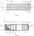
FIG. 5 is a schematic cross-sectional view of the imaging device ofFIG. 3 along a line V-V. -
FIG. 6 is a schematic cross-sectional view of the imaging device ofFIG. 3 along a line VI-VI. -
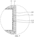
FIG. 7 is a schematic partial cross-sectional view of the imaging device ofFIG. 3 along a line VII-VII. -
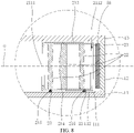
FIG. 8 is a schematic partial cross-sectional view of the imaging device ofFIG. 3 along the line VI-VI according to some embodiments of the present disclosure. -
FIG. 9 is another schematic partial cross-sectional view of the imaging device ofFIG. 3 along the line VI-VI according to some embodiments of the present disclosure. -
FIG. 10 is yet another schematic partial cross-sectional view of the imaging device ofFIG. 3 along the line VI-VI according to some embodiments of the present disclosure. -
FIG. 11 is another schematic cross-sectional view of the imaging device ofFIG. 3 along the line VI-VI according to some embodiments of the present disclosure. - Embodiments of the present disclosure will be further described below in conjunction with accompanying drawings. Same or similar reference numerals in the accompanying drawings indicate same or similar elements or elements with same or similar functions throughout.
- Furthermore, the embodiments of the present disclosure described below in conjunction with the accompanying drawings are exemplary, and are only used to explain the embodiments of the present disclosure, and should not be construed as limiting the present disclosure.
- In the present disclosure, unless otherwise specifically specified or limited, a description that a first feature is "on" or "under" a second feature may indicate that the first feature directly contacts the second feature, or that the first feature and the second feature are indirectly contacted through an intermediary. Furthermore, a description that the first feature is "on", "above", or "on top of' the second feature may indicate that the first feature is right or obliquely "on", "above", or "on top of' the second feature, or just means that a sea-level elevation of the first feature is greater than a sea-level elevation of the second feature. A description that the first feature "under", "below", or "on bottom of' the second feature may indicate that the first feature is right or obliquely "under", "below", or "on bottom of' the second feature, or just means that the sea-level elevation of the first feature is less than the sea-level elevation of the second feature.
- Please refer to
FIG. 3 to FIG. 6 . In some embodiments, animaging device 100 comprises ahousing 10 and afirst lens module 20. Thehousing 10 comprises abase plate 11 and aside plate 12 disposed on thebase plate 11. Theside plate 12 is provided with asliding groove 125. Thefirst lens module 20 comprises acasing 21 and alens group 22 disposed in thecasing 21. Thecasing 21 comprises amain body 211 and a slidingblock 212 connected to themain body 211. An extending direction of thesliding groove 125 is parallel to an optical axis O of thelens group 22. Thesliding block 212 is slidably disposed in thesliding groove 125. Sliding of thecasing 21 drives sliding of thelens group 22. - Please refer to
FIG. 4 andFIG. 5 . In some embodiments, in a direction perpendicular to abearing surface 111 of thebase plate 11, opposite sides of thesliding block 212 respectively abut against opposite sides of an inner wall of thesliding groove 125. - Please refer to
FIG. 4 andFIG. 5 . In some embodiments, theside plate 12 is further provided with aninstallation groove 126. One end of theinstallation groove 126 penetrates a surface of theside plate 12 away from thebase plate 11, and the other end of theinstallation groove 126 communicates with thesliding groove 125. Thesliding block 212 is disposed in thesliding groove 125 through theinstallation groove 126. - Please refer to
FIG. 3 to FIG. 6 . In some embodiments, an extending direction of theinstallation groove 126 is perpendicular or inclined to the extending direction of the slidinggroove 125. - Please refer to
FIG. 5 . In some embodiments, thehousing 10 further comprises acover plate 13 disposed on theside plate 12 and comprising acover plate body 131 and a resistingportion 132. The resistingportion 132 is disposed on both sides of thecover plate body 131 and in theinstallation groove 126. A length of the resistingportion 132 in a direction perpendicular to thebearing surface 111 of thebase plate 11 is equal to a depth of theinstallation groove 126 in the direction perpendicular to thebearing surface 111. - Please refer to
FIG. 5 . In some embodiments, when the resistingportion 132 is disposed in theinstallation groove 126, the resistingportion 132 completely fills theinstallation groove 126. - Please refer to
FIG. 4 andFIG. 8 . In some embodiments, thecasing 21 further comprises atop surface 213 and abottom surface 214 opposite to each other. Thetop surface 213 faces thecover plate 13. Thebottom surface 214 faces thebase plate 11 and is provided with afirst groove 215. A surface of thebase plate 11 facing thebottom surface 214 is provided with afirst slide rail 112. Thefirst lens module 20 further comprises a first rollingball 23 disposed in thefirst groove 215 and abuts against a bottom of thefirst slide rail 112. - Please refer to
FIG. 4 andFIG. 9 . In some embodiments, thetop surface 213 is provided with asecond groove 216. Thefirst lens module 20 further comprises asecond rolling ball 24 disposed in thesecond groove 216 and abuts against thecover plate 13. - Please refer to
FIG. 4 andFIG. 10 . In some embodiments, a surface of thecover plate 13 facing thetop surface 213 is provided with a second slide rail 134. Thesecond rolling ball 24 is disposed in thesecond groove 216 and abuts against a bottom of the second slide rail 134. - Please refer to
FIG. 11 . In some embodiments, a number of thefirst lens module 20 may be multiple. The slidingblock 212 of eachfirst lens module 20 is slidably disposed in the slidinggroove 125. Thehousing 10 further comprises one or more spacer plates 15 connected to theside plate 12. Two adjacentfirst lens modules 20 are separated by one spacer plate 15. - Please refer to
FIG. 1 ,FIG. 3 , andFIG. 6 . Anelectronic device 1000 of the present disclosure comprises achassis 200 and animaging device 100 combined with thechassis 200. Theimaging device 100 comprises ahousing 10 and afirst lens module 20. Thehousing 10 comprises abase plate 11 and aside plate 12 disposed on thebase plate 11. Theside plate 12 is provided with a slidinggroove 125. Thefirst lens module 20 comprises acasing 21 and alens group 22 disposed in thecasing 21. Thecasing 21 comprises amain body 211 and a slidingblock 212 connected to themain body 211. An extending direction of the slidinggroove 125 is parallel to an optical axis O of thelens group 22. The slidingblock 212 is slidably disposed in the slidinggroove 125. Sliding of thecasing 21 drives sliding of thelens group 22. - Please refer to
FIG. 4 andFIG. 5 . In some embodiments, in a direction perpendicular to abearing surface 111 of thebase plate 11, opposite sides of the slidingblock 212 respectively abut against opposite sides of an inner wall of the slidinggroove 125. - Please refer to
FIG. 4 andFIG. 5 . In some embodiments, theside plate 12 is further provided with aninstallation groove 126. One end of theinstallation groove 126 penetrates a surface of theside plate 12 away from thebase plate 11, and the other end of theinstallation groove 126 communicates with the slidinggroove 125. The slidingblock 212 is disposed in the slidinggroove 125 through theinstallation groove 126. - Please refer to
FIG. 3 to FIG. 6 . In some embodiments, an extending direction of theinstallation groove 126 is perpendicular or inclined to the extending direction of the slidinggroove 125. - Please refer to
FIG. 5 . In some embodiments, thehousing 10 further comprises acover plate 13 disposed on theside plate 12 and comprising acover plate body 131 and a resistingportion 132. The resistingportion 132 is disposed on both sides of thecover plate body 131 and in theinstallation groove 126. A length of the resistingportion 132 in a direction perpendicular to thebearing surface 111 of thebase plate 11 is equal to a depth of theinstallation groove 126 in the direction perpendicular to thebearing surface 111. - Please refer to
FIG. 5 . In some embodiments, when the resistingportion 132 is disposed in theinstallation groove 126, the resistingportion 132 completely fills theinstallation groove 126. - Please refer to
FIG. 4 andFIG. 8 . In some embodiments, thecasing 21 further comprises atop surface 213 and abottom surface 214 opposite to each other. Thetop surface 213 faces thecover plate 13. Thebottom surface 214 faces thebase plate 11 and is provided with afirst groove 215. A surface of thebase plate 11 facing thebottom surface 214 is provided with afirst slide rail 112. Thefirst lens module 20 further comprises a first rollingball 23 disposed in thefirst groove 215 and abuts against a bottom of thefirst slide rail 112. - Please refer to
FIG. 4 andFIG. 9 . In some embodiments, thetop surface 213 is provided with asecond groove 216. Thefirst lens module 20 further comprises asecond rolling ball 24 disposed in thesecond groove 216 and abuts against thecover plate 13. - Please refer to
FIG. 4 andFIG. 10 . In some embodiments, a surface of thecover plate 13 facing thetop surface 213 is provided with a second slide rail 134. Thesecond rolling ball 24 is disposed in thesecond groove 216 and abuts against a bottom of the second slide rail 134. - Please refer to
FIG. 11 . In some embodiments, a number of thefirst lens module 20 may be multiple. The slidingblock 212 of eachfirst lens module 20 is slidably disposed in the slidinggroove 125. Thehousing 10 further comprises one or more spacer plates 15 connected to theside plate 12. Two adjacentfirst lens modules 20 are separated by one spacer plate 15. - Please refer to
FIG. 1 andFIG. 2 . Theelectronic device 1000 comprises thechassis 200 and theimaging device 100 combined with thechassis 200. Specifically, theelectronic device 1000 may be a mobile phone, a tablet computer, a monitor, a notebook computer, a teller machine, a gate machine, a smart watch, a head-mounted display device, a game console, or the like. The embodiments of the present disclosure are described by taking theelectronic device 1000 as a mobile phone as an example. It can be understood that a specific form of theelectronic device 1000 is not limited to a mobile phone. - The
chassis 200 may be configured to install theimaging device 100. In other words, thechassis 200 may be configured as an installation carrier for theimaging device 100. Theelectronic device 1000 further comprises afront surface 901 and aback surface 902. Theimaging device 100 may be disposed on thefront surface 901 as a front camera. Theimaging device 100 may also be disposed on theback surface 902 as a rear camera. In the embodiments of the present disclosure, theimaging device 100 is disposed on theback surface 902 as a rear camera. In addition to installing theimaging device 100, thechassis 200 may also be configured to install functional modules such as a power supply device and a communication device of theelectronic device 1000. Thechassis 200 provides protections such as dustproof, anti-drop, and waterproof for the functional modules such as theimaging device 100, the power supply device, and the communication device. - Please refer to
FIG. 3 to FIG. 6 , theimaging device 100 comprises thehousing 10 and thefirst lens module 20. Thefirst lens module 20 is received and installed in thehousing 10. - The
housing 10 comprises thebase plate 11 and theside plate 12 disposed on thebase plate 11. Theside plate 12 is provided with the slidinggroove 125. Thefirst lens module 20 comprises thecasing 21 and thelens group 22 disposed in thecasing 21. Thecasing 21 comprises themain body 211 and the slidingblock 212 connected to themain body 211. The extending direction of the slidinggroove 125 is parallel to the optical axis O of thelens group 22. The slidingblock 212 is slidably disposed in the slidinggroove 125. The sliding of thecasing 21 drives the sliding of thelens group 22. - A shape of the sliding
block 212 matches a shape of the slidinggroove 125. For example, the slidinggroove 125 is a rectangular groove, and the slidingblock 212 is a rectangular block. That is, cross-sections of the slidinggroove 125 and the slidingblock 212 cut by a plane (i.e. a plane parallel to a line VII-VII inFIG. 3 , an explanation for this below is same) perpendicular to the optical axis O are both rectangular. Alternatively, the slidinggroove 125 is a semicircular groove, and the slidingblock 212 is a semicircular block. That is, the cross-sections of the slidinggroove 125 and the slidingblock 212 cut by the plane perpendicular to the optical axis O are both semicircular. Alternatively, the slidinggroove 125 is a rectangular groove, and the slidingblock 212 is a semicircular block. That is, the cross-section of the slidinggroove 125 cut by the plane perpendicular to the optical axis O is rectangular, and the cross-section of the slidingblock 212 cut by the plane perpendicular to the optical axis O is semicircular. The cross-sections of the slidinggroove 125 and the slidingblock 212 cut by the plane perpendicular to the optical axis O may also be other shapes, such as other regular shapes or irregular shapes, as long as the slidingblock 212 can match the slidinggroove 125 to slide in the slidinggroove 125, which will not be described in detail herein. In this embodiment, the cross-sections of the slidinggroove 125 and the slidingblock 212 cut by the plane perpendicular to the optical axis O both are irregular shapes. Each of the irregular shape is a closed "D" shape composed of a straight line and an arc. A curvature of an arc corresponding to the inner wall of the slidinggroove 125 is same as a curvature of an arc corresponding to an outer wall of the slidingblock 212, so that the slidingblock 212 and the slidinggroove 125 can be better matched. - Recently, it is generally necessary to dispose both a telephoto lens and a wide-angle lens at a same time, so that telephotography and wide-angle photography can be realized by switching the lenses. A single lens cannot realize the telephotography and the wide-angle photography.
- In the
imaging device 100 of the present disclosure, the slidingblock 212 of thecasing 21 cooperates with the slidinggroove 125 of theside plate 12 of thehousing 10 to move thelens group 22, so that a focal length of theimaging device 100 is variable. Therefore, the telephotography and the wide-angle photography can be realized without disposing a telephoto lens and a wide-angle lens at a same time. - Please refer to
FIG. 3 andFIG. 4 . In this embodiment, theimaging device 100 comprises thehousing 10 and thefirst lens module 20. - The
housing 10 comprises thebase plate 11, theside plate 12, and thecover plate 13. Thebase plate 11, theside plate 12, and thecover plate 13 define a receivingspace 14. Thefirst lens module 20 is disposed in the receivingspace 14. - The
base plate 11 comprises the bearingsurface 111. The bearingsurface 111 is configured to bear theside plate 12 and thefirst lens module 20. Thebase plate 11 may be a rectangular parallelepiped structure, a cube structure, a cylindrical structure, or a structure of other shapes, which is not limited herein. In this embodiment, thebase plate 11 is a rectangular parallelepiped structure. - The
side plate 12 is disposed around an edge of thebase plate 11. Theside plate 12 is perpendicular to thebase plate 11. Theside plate 12 may be disposed on thebase plate 11 by gluing, screwing, snapping, or the like. Theside plate 12 may also be integrally formed with thebase plate 11. - Please refer to
FIG. 5 , theside plate 12 comprises aninner surface 121, anouter surface 122, anupper surface 123, and alower surface 124. Theinner surface 121 and theouter surface 122 are opposite to each other. Theinner surface 121 is located in the receivingspace 14. Theouter surface 122 is located outside the receivingspace 14. Theinner surface 121 is connected to both theupper surface 123 and thelower surface 124. Theouter surface 122 is also connected to both theupper surface 123 and thelower surface 124. Theupper surface 123 and thelower surface 124 are opposite to each other. Thelower surface 124 is connected to thebearing surface 111 of thebase plate 11. Theupper surface 123 is away from the bearingsurface 111 of thebase plate 11. - The
side plate 12 further comprises afirst side plate 127 and asecond side plate 128 parallel to the optical axis O. Thefirst side plate 127 and thesecond side plate 128 are opposite to each other. Aninner surface 121 of thefirst side plate 127 and/or aninner surface 121 of thesecond side plate 128 are provided with the slidinggroove 125 and theinstallation groove 126. For example, theinner surface 121 of thefirst side plate 127 is provided with the slidinggroove 125 and theinstallation groove 126. Alternatively, theinner surface 121 of thesecond side plate 128 is provided with the slidinggroove 125 and theinstallation groove 126. Alternatively, both theinner side 121 of thefirst side plate 127 and theinner side 121 of thesecond side plate 128 are provided with the slidinggroove 125 and theinstallation groove 126. In this embodiment, both theinner side 121 of thefirst side plate 127 and theinner side 121 of thesecond side plate 128 are provided with the slidinggroove 125 and theinstallation groove 126. The extending direction of the slidinggroove 125 is parallel to thebearing surface 111. - The sliding
groove 125 communicates with the receivingspace 14. The extending direction of the slidinggroove 125 is parallel to the optical axis O. A groove depth of the slidinggroove 125 is less than a thickness of theside plate 12. In other words, the slidinggroove 125 does not penetrate theouter surface 122 of theside plate 12. In other embodiments, the slidinggroove 125 penetrates theouter surface 122 of theside plate 12, so that the receivingspace 14 communicates with outside. A number of the slidinggrooves 125 formed on theinner surface 121 of thefirst side plate 127 and theinner surface 121 of thesecond side plate 128 may be one or more. For example, theinner surface 121 of thefirst side plate 127 is provided with one slidinggroove 125, and theinner surface 121 of thesecond side plate 128 is provided with one slidinggroove 125. For another example, theinner surface 121 of thefirst side plate 127 is provided with two slidinggrooves 125, and theinner surface 121 of thesecond side plate 128 is provided with two slidinggrooves 125. For yet another example, theinner surface 121 of thefirst side plate 127 is provided with one slidinggroove 125, and theinner surface 121 of thesecond side plate 128 is provided with two slidinggrooves 125, and so on, which will not be listed herein. In this embodiment, both theinner surface 121 of thefirst side plate 127 and theinner surface 121 of thesecond side plate 128 are provided with one slidinggroove 125. The cross-section of the slidinggroove 125 cut by the plane perpendicular to the optical axis O is rectangular, semicircular, or other shapes, such as other regular shapes or irregular shapes. Please refer toFIG. 7 . In this embodiment, the cross-section of the slidinggroove 125 cut by the plane perpendicular to the optical axis O is an irregular shape. The irregular shape is a closed "D" shape composed of a straight line and an arc. A cross-sectional shape of the inner wall of the slidinggroove 125 corresponds to the arc of the "D" shape. - The
installation groove 126 communicates with the receivingspace 14. One end of theinstallation groove 126 penetrates theupper surface 123 of theside plate 12. The other end of theinstallation groove 126 communicates with the slidinggroove 125. The extending direction of theinstallation groove 126 may be perpendicular or inclined to the extending direction of the slidinggroove 125. For example, the extending direction of theinstallation groove 126 is perpendicular to the optical axis O. Alternatively, the extending direction of theinstallation groove 126 is inclined at a certain angle (not 0°, but 30°, 60°, 120°, etc.) with respect to the optical axis O. In this embodiment, the extending direction of theinstallation groove 126 is perpendicular to the optical axis O. A number of theinstallation grooves 126 formed on theinner surface 121 of thefirst side plate 127 and theinner surface 121 of thesecond side plate 128 may be one or more. For example, theinner surface 121 of thefirst side plate 127 is provided with oneinstallation groove 126, and theinner surface 121 of thesecond side plate 128 is provided with oneinstallation groove 126. For another example, theinner surface 121 of thefirst side plate 127 is provided with twoinstallation grooves 126, and theinner surface 121 of thesecond side plate 128 is provided with twoinstallation grooves 126. For yet another example, theinner surface 121 of thefirst side plate 127 is provided with oneinstallation groove 126, and theinner surface 121 of thesecond side plate 128 is provided with twoinstallation grooves 126, and so on, which will not be listed herein. In this embodiment, theinner surface 121 of thefirst side plate 127 and theinner surface 121 of thesecond side plate 128 are both provided with twoinstallation grooves 126. - The
cover plate 13 is disposed on theside plate 12. Specifically, thecover plate 13 may be disposed on theupper surface 123 of theside plate 12 by clamping, screwing, gluing, or the like. Thecover plate 13 comprises thecover plate body 131 and a plurality of the resistingportions 132. Thecover plate body 131 is connected to theupper surface 123 of theside plate 12. Thecover plate body 131 is provided with alight entrance 133. A depth direction of thelight entrance 133 may be perpendicular to the optical axis O, so that theimaging device 100 has a periscope structure as a whole. The resistingportions 132 are disposed on two opposite sides of thecover plate body 131. Specifically, the resistingportions 132 are disposed on two sides of thecover plate 13 respectively corresponding to thefirst side plate 127 and thesecond side plate 128. When thecover plate 13 is disposed on theside plate 12, the resistingportions 132 are disposed in theinstallation grooves 126. As shown inFIG. 3 , a direction parallel to the optical axis O is defined as an x direction, a direction perpendicular to theinner surface 121 of thefirst side plate 127 is defined as a y direction, and a direction perpendicular to thebearing surface 111 is defined as a z direction. The x direction, the y direction, and the z direction are perpendicular to each other. The length L of the resistingportions 132 in the direction perpendicular to thebearing surface 111 of thebase plate 11 is equal to the depth H of theinstallation grooves 126 in the z direction. The resistingportions 132 are disposed in theinstallation grooves 126, which may be that each of the resistingportions 132 is disposed in oneinstallation groove 126 and occupies a part of a space of theinstallation groove 126. The resistingportions 132 are disposed in theinstallation grooves 126, which may be that each of the resistingportions 132 is disposed in oneinstallation groove 126 and completely fills theinstallation groove 126. In this embodiment, when the resistingportions 132 are disposed in theinstallation grooves 126, the resistingportions 132 completely fill theinstallation grooves 126 so that the resistingportions 132 and theinstallation grooves 126 are combined more firmly, and thus thecover plate 13 and theside plate 12 are connected more firmly. In other embodiments, thelight entrance 133 is not a via hole, but a light-transmitting physical structure. Light can enter the receivingspace 14 from the light-transmitting physical structure. - Please refer to
FIG. 4 to FIG. 6 , thefirst lens module 20 comprises thecasing 21 and thelens group 22. Thelens group 22 is disposed in thecasing 21. When thecasing 21 slides, thecasing 21 drives thelens group 22 to slide. A number of thefirst lens module 20 is one or more. For example, the number of thefirst lens module 20 is one, two, three, or the like. In this embodiment, the number of thefirst lens module 20 is one. - The
casing 21 comprises themain body 211 and the slidingblock 212. Themain body 211 is fixedly connected to the slidingblock 212. - The
main body 211 comprises a light-inlet 2111 and a light-outlet 2112 corresponding to thelens group 22. Themain body 211 is provided with anaccommodating space 2113 for accommodating thelens group 22. Theaccommodating space 2113 communicates with the receivingspace 14 through the light-inlet 2111 and the light-outlet 2112. - Please refer to
FIG. 4 andFIG. 5 , the slidingblock 212 is movably disposed in the slidinggroove 125. A number of the slidingblock 212 matches a number of theinstallation groove 126. The number of the slidingblock 212 matches the number of theinstallation groove 126, which means that a number of the slidingblock 212 located on a surface of themain body 211 facing theinner surface 121 of thefirst side plate 127 is same as a number of theinstallation groove 126 formed on theinner surface 121 of thefirst side plate 127, both are two. And, a number of the slidingblock 212 located on a surface of themain body 211 facing theinner surface 121 of thesecond side plate 128 is same as a number of theinstallation groove 126 formed on theinner surface 121 of thesecond side plate 128, both are two, and the two slidingblocks 212 correspond to the twoinstallation grooves 126 one-to-one. In other embodiments, the number of slidingblock 212 may be less than the number ofinstallation grooves 126. For example, the number of the slidingblock 212 located on the surface of themain body 211 facing theinner surface 121 of thefirst side plate 127 is less than the number of theinstallation groove 126 formed on theinner surface 121 of thefirst side plate 127, and the number of the slidingblock 212 located on the surface of themain body 211 facing theinner surface 121 of thesecond side plate 128 is less than the number of theinstallation groove 126 formed on theinner surface 121 of thesecond side plate 128. Moreover, a length d1 of the slidingblocks 212 in the x direction is less than or equal to a length d2 of theinstallation grooves 126 in the x direction, so as to facilitate the slidingblocks 212 to slide into the slidinggrooves 125 through theinstallation grooves 126. - The cross-section of each of the
installation grooves 126 cut by the plane perpendicular to the optical axis O is rectangular, semicircular, or other shapes, such as other regular shapes or irregular shapes, as long as a shape of one slidingblock 212 matches a shape of one corresponding slidinggroove 125. Specifically, the shape of one slidingblock 212 matches the shape of one corresponding slidinggroove 125, which means that when a cross-section of the slidinggroove 125 formed on theinner side surface 121 of thefirst side plate 127 cut by the plane perpendicular to the optical axis O is rectangular, a cross-section of the slidingblock 212 located on the surface of themain body 211 facing theinner surface 121 of thefirst side plate 127 is also rectangular. when a cross-section of the slidinggroove 125 formed on theinner side surface 121 of thesecond side plate 128 cut by the plane perpendicular to the optical axis O is rectangular, a cross-section of the slidingblock 212 located on the surface of themain body 211 facing theinner surface 121 of thesecond side plate 128 is also rectangular. when a cross-section of the slidinggroove 125 formed on theinner side surface 121 of thefirst side plate 127 cut by the plane perpendicular to the optical axis O is rectangular, a cross-section of the slidingblock 212 located on the surface of themain body 211 facing theinner surface 121 of thefirst side plate 127 is also semicircular. when a cross-section of the slidinggroove 125 formed on theinner side surface 121 of thesecond side plate 128 cut by the plane perpendicular to the optical axis O is semicircular, a cross-section of the slidingblock 212 located on the surface of themain body 211 facing theinner surface 121 of thesecond side plate 128 is also semicircular, and so on, which will not be listed herein. - Please refer to
FIG. 7 . In this embodiment, the cross-section of the slidingblock 212 cut by the plane perpendicular to the optical axis O is an irregular shape. The irregular shape is a closed "D" shape composed of a straight line and an arc. A cross-sectional shape of the outer wall of the slidingblock 212 corresponds to the arc of the "D" shape. The shape of one slidingblock 212 matches the shape of one corresponding slidinggroove 125, which means that the curvature of the arc corresponding to the inner wall of the slidinggroove 125 is the same as the curvature of the arc corresponding to the outer wall of the slidingblock 212. Therefore, the slidingblock 212 and the slidinggroove 125 can be better matched. - In z direction, the opposite sides of the sliding
block 212 respectively abut against the opposite sides of an inner wall of the slidinggroove 125. Specifically, when the slidingblocks 212 are disposed in the slidinggrooves 125, in the z direction, opposite sides of the slidingblock 212 corresponding to thefirst side plate 127 are abutted by opposite sides of the inner wall of the slidinggroove 125 on theinner surface 121 of thefirst side plate 127. And, opposite sides of the slidingblock 212 corresponding to thesecond side plate 128 are abutted by opposite sides of the inner wall of the slidinggroove 125 on theinner surface 121 of thesecond side plate 128. As a result, movement of the slidingblocks 212 in the z direction is restricted, which prevents the slidingblocks 212 from shaking or tilting in the z direction, thereby ensuring that an imaging quality of thefirst lens module 20 is not affected. - The
lens group 22 is disposed in theaccommodating space 2113. Specifically, thelens group 22 may be disposed in theaccommodating space 2113 by gluing, screwing, snapping, or the like. Thelens group 22 may be a separate lens, and the lens is a convex lens or a concave lens. Alternatively, thelens group 22 comprises a plurality of (such as two, three, etc.) lenses. The lenses may all be convex lenses or concave lenses. Alternatively, some of the lenses may be convex lenses, while others may be concave lenses. In this embodiment, thelens group 22 comprises three lenses. - Please refer to
FIG. 4 andFIG. 6 , theimaging device 100 further comprises asecond lens module 30, aprism assembly 40, and aphotosensitive element 50. - The
second lens module 30 comprises a fixedcasing 31 and alens group 32. Thelens group 32 is disposed in the fixedcasing 31. - The fixed
casing 31 is disposed on thebearing surface 111 of thebase plate 11. Specifically, the fixedcasing 31 may be fixedly disposed on thebearing surface 111 by gluing, screwing, snapping, or the like. The fixedcasing 31 may also be integrally formed with thebase plate 11. The fixedcasing 31 comprises a light-inlet hole 311, a light-outlet hole 312, and a receivingcavity 313. The receivingcavity 313 communicates with the receivingspace 14 through the light-inlet hole 311 and the light-outlet hole 312. The light-outlet hole 312 faces the light-inlet 2111 of thefirst lens module 20. The light-inlet hole 31 1faces thelens group 32. - The
lens group 32 is disposed in the receivingcavity 313. Thelens group 32 may be disposed in the fixedcasing 31 by gluing, screwing, snapping, or the like. Thelens group 32 may be a separate lens, and the lens is a convex lens or a concave lens. Alternatively, thelens group 32 comprises a plurality of (such as two, three, etc.) lenses. The lenses may all be convex lenses or concave lenses. Alternatively, some of the lenses may be convex lenses, while others may be concave lenses. In this embodiment, thelens group 32 comprises two lenses. - The
prism assembly 40 is disposed on thebearing surface 111 of thebase plate 11 and in the receivingspace 14. Theprism assembly 40 comprises a mountingplatform 41 and aprism 42. - The mounting
platform 41 is disposed on thebearing surface 111 of thebase plate 11. Specifically, the mountingplatform 41 may be disposed on thebearing surface 111 by gluing, screwing, snapping, etc. The mountingplatform 41 may also be integrally formed with thebase plate 11. The mountingplatform 41 comprises a light-inlet viahole 411, a light-outlet viahole 412, and anaccommodating cavity 413. Theaccommodating cavity 413 communicates with the receivingspace 14 through the light-inlet viahole 411 and the light-outlet viahole 412. The light-inlet viahole 411 faces thelight entrance 133 of thecover plate 13. The light-outlet viahole 412 faces the light-inlet hole 311 of thesecond lens module 30. - The
prism 42 is disposed in theaccommodating cavity 413. Theprism 42 may be disposed on the mountingplatform 41 by gluing, snapping, or the like. Theprism 42 comprises anincident surface 421, areflective surface 422, and anemission surface 423. Thereflective surface 422 obliquely connects theincident surface 421 and theemission surface 423. An angle between thereflective surface 422 and thebearing surface 111 may be 15 degrees, 30 degrees, 45 degrees, 60 degrees, 75 degrees, or the like. In this embodiment, the angle between thereflective surface 422 and thebearing surface 111 is 45 degrees. Theincident surface 421 faces the light-inlet viahole 411, and theemission surface 423 faces the light-outlet viahole 412. Theprism 42 is configured to change an exit direction of a light entering the light-inlet viahole 411. Theprism 42 may be a triangular prism. Specifically, a cross-section of theprism 42 is a right triangle. Two right-angled sides of the right triangle are theincident surface 421 and theemission surface 423, respectively. A hypotenuse of the right triangle is thereflective surface 422. - The
photosensitive element 50 is disposed on theinner surface 121 of theside plate 12. Thephotosensitive element 50 faces the light-outlet 2112 of thefirst lens module 20. Thephotosensitive element 50 may be a complementary metal oxide semiconductor (CMOS)photosensitive element 50 or a charge-coupled device (CCD)photosensitive element 50. - Please refer to
FIG. 4 to FIG. 6 . In this embodiment, theprism assembly 40, thesecond lens module 30, and thefirst lens module 20 are sequentially disposed in the receivingspace 14 along the optical axis O. Theprism assembly 40 and thesecond lens module 30 are fixedly disposed on thebearing surface 111 of thebase plate 11. The slidingblocks 212 pass through theinstallation grooves 126 and then slide into the slidinggrooves 125, so that the slidingblocks 212 are slidably disposed in the slidinggrooves 125, and thefirst lens module 20 is slidably connected to theside plate 12. The slidingblocks 212 are fixedly connected to themain body 211. When the slidingblocks 212 slide in the slidinggrooves 125, a distance between thefirst lens module 20 and thesecond lens module 30 changes. After theprism assembly 40, thesecond lens module 30, and thefirst lens module 20 are disposed, thecover plate 13 is disposed on theside plate 12. The resistingportions 132 of thecover plate 13 completely fill theinstallation grooves 126. It can be understood that when thefirst lens module 20 is sliding and the slidingblocks 212 pass through positions of the slidinggrooves 125 corresponding to theinstallation grooves 126, the slidingblocks 212 may shake or tilt in the direction of the bearingsurface 11 because there is no inner wall of the slidinggrooves 125 against theslider 212. Accordingly, after the resistingportions 132 completely fill theinstallation grooves 126, the resistingportions 132 can abut against the slidingblocks 212, thereby preventing the slidingblocks 212 from shaking or tilting in the z direction. - It should be noted that the
electronic device 1000 may further comprise a drive structure. For example, the drive structure may be a magnetic drive structure disposed in the receivingspace 14. The magnetic drive structure comprises a magnetic coil and a magnet. The magnetic coil may be disposed between thesecond lens module 30 and thefirst lens module 20, between theprism assembly 40 and thesecond lens module 30, or between thefirst lens module 20 and thephotosensitive element 50. The magnet may be disposed on themain body 211 of thefirst lens module 20. When the magnetic coil has electricity in different directions, corresponding magnetic fields will be generated, thereby controlling thefirst lens module 20 provided with the magnet to move away from or close to the magnetic coil, and causing the slidingblocks 212 to slide in the slidinggrooves 125. - For another example, the drive structure may also be a linear motor. A stator of the linear motor may be fixedly disposed on the
inner side 121. A mover of the linear motor extends from the stator and is connected to themain body 211. When the mover telescopically moves in a straight line, themain body 211 is driven to move linearly, so that slidingblocks 212 slide in the slidinggrooves 125. A number of the linear motor may be two, one is disposed on theinner side 121 of thefirst side plate 127, and the other is disposed on theinner side 121 of thesecond side plate 128. The linear motor may be disposed on any side of thesecond lens module 30. For example, the linear motor may be disposed between thesecond lens module 30 and thefirst lens module 20, between theprism assembly 40 and thesecond lens module 30, or between thefirst lens module 20 and thephotosensitive element 50. The drive structure may also be other structures, such as a hydraulic structure, a piezoelectric motor, etc., which will not be listed herein. - During imaging, light passes through the
light entrance 133 of thecover plate 13 and the light-inlet viahole 411 of theprism assembly 40, is reflected by thereflective surface 422 of theprism 42, and then exits from the light-outlet viahole 412. Then, the light sequentially passes through the light-inlet hole 311, thelens group 32, and the light-outlet hole 312 of thesecond lens module 30, and the light-inlet 2111, thelens group 22, and the light-outlet 2112 of thefirst lens module 20, and finally reaches thephotosensitive element 50 for the imaging. A relative distance between thefirst lens module 20 and thesecond lens module 30 may be changed by relative movement of the slidingblocks 212 in the slidinggrooves 125, thereby changing the focal length of theimaging device 100 and achieving zooming of theimaging device 100. - Please refer to
FIG. 4 andFIG. 8 . In some embodiments, thecasing 21 further comprises thetop surface 213 and thebottom surface 214 opposite to each other. Thetop surface 213 faces thecover plate 13. Thebottom surface 214 faces the bearingsurface 111 of thebase plate 11. Thebottom surface 214 is provided with thefirst groove 215. The surface (i.e. the bearing surface 111) of thebase plate 11 facing thebottom surface 214 is provided with thefirst slide rail 112. Thefirst lens module 20 further comprises the first rollingball 23 disposed in thefirst groove 215 and abuts against the bottom of thefirst slide rail 112. - Specifically, a shape of the
first groove 215 matches a shape of the first rollingball 23. For example, the first rollingball 23 is spherical and has a small moving resistance. Thefirst groove 215 is a semicircular groove. A diameter of the first rollingball 23 is equal to a diameter of thefirst groove 215. In other words, a half of the first rollingball 23 is disposed in thefirst groove 215. Thefirst rolling ball 23 is tightly combined with thefirst groove 215, so that when the first rollingball 23 moves, thecasing 21 of thefirst lens module 20 is driven to move. The bearingsurface 111 is provided with thefirst slide rail 112. Thefirst slide rail 112 may be a groove formed on thebearing surface 111 with an extending direction parallel to the optical axis O. The first slidingrail 112 may also be a boss disposed on thebearing surface 111 with an extending direction parallel to the optical axis O. A surface of the boss facing thebottom surface 214 of thecasing 21 is provided with a groove matching the first rollingball 23. In this embodiment, thefirst slide rail 112 is a groove formed on thebearing surface 111 with an extending direction parallel to the optical axis O. After thefirst lens module 20 is disposed in the receivingspace 14, a part of the first rollingball 23 is disposed in thefirst slide rail 112 and abuts against the bottom of thefirst slide rail 112. A cross-section of an inner wall of thefirst slide rail 112 cut by the plane perpendicular to the optical axis O is a first arc. A cross-section of an outer contour of the first rollingball 23 cut by the plane perpendicular to the optical axis O is a second arc. A curvature of the first arc is same as a curvature of the second arc. When the first rollingball 23 rotates along thefirst slide rail 112, in the y direction, opposite sides of an outer wall of the first rollingball 23 are abutted by opposite sides of the inner wall of thefirst slide rail 112, thereby restricting movement of the first rollingball 23 in the y direction, and preventing thefirst lens module 20 from shaking or tilting in the y direction. - A number of the
first groove 215 is one or more. For example, the number of thefirst groove 215 is one, two, three, four, or more. In this embodiment, the number of thefirst groove 215 is four. A number of the first rollingball 23 may also be one or more. In this embodiment, the number of the first rollingball 23 is same as the number of thefirst groove 215, which is also four. The fourfirst grooves 215 are formed on thebottom surface 214 of thecasing 21 at intervals. - A number of the
first slide rail 112 may be one or more. The number of thefirst slide rail 112 is determined according to positions of the fourfirst grooves 215. For example, if centers of the fourfirst grooves 215 are on a straight line parallel to the optical axis O, only onefirst slide rail 112 is needed. For another example, the fourfirst grooves 215 are divided into two groups. Each group comprises twofirst grooves 215. A line connecting centers of the twofirst grooves 215 in each group is parallel to the optical axis O. The line connecting the centers of the twofirst grooves 215 in each group does not overlap. Therefore, two first slide rails 112 are required, which respectively correspond to the two groups each comprising the twofirst grooves 215. In this embodiment, the fourfirst grooves 215 are divided into the two groups, each group comprises the twofirst grooves 215, and the line connecting the centers of the twofirst grooves 215 in each group is parallel to each other and is parallel to the optical axis O. The fourfirst grooves 215 may be enclosed in a rectangle. Therefore, when the four first rollingballs 23 slide in the two first slide rails 112, the four first rollingballs 23 are restricted in the two first slide rails 112. And, in the y direction, the opposite sides of the outer wall of each of the first rollingballs 23 are abutted by the opposite sides of the inner wall of one correspondingfirst slide rail 112, thereby preventing thefirst lens module 20 from shaking or tilting in the y direction, and ensuring that an imaging quality of theimaging device 100 is not affected. - Please refer to
FIG. 4 andFIG. 9 . In some embodiments, thetop surface 213 of thecasing 21 is provided with thesecond groove 216. Thefirst lens module 20 further comprises the second rollingball 24 disposed in thesecond groove 216 and abuts against thecover plate 13. - Specifically, a shape of the
second groove 216 matches a shape of the second rollingball 24. For example, the second rollingball 24 is spherical and has a small moving resistance. Thesecond groove 216 is a semicircular groove. A diameter of the second rollingball 24 is equal to a diameter of thesecond groove 216. In other words, a half of the second rollingball 24 is disposed in thesecond groove 216. Thesecond rolling ball 24 is tightly combined with thesecond groove 216, so that when the second rollingball 24 moves, thecasing 21 of thefirst lens module 20 is driven to move. A number of thesecond groove 216 is one or more. For example, the number of thesecond groove 216 is one, two, three, four, or more. In this embodiment, the number of thesecond groove 216 is four. A number of the second rollingball 24 may also be one or more. In this embodiment, the number of the second rollingball 24 is same as the number of thesecond groove 216, which is also four. The foursecond grooves 216 are formed on the top surface of thecasing 21 at intervals. The second rollingballs 24 are disposed in thesecond grooves 216 and abut against thecover plate 13, so that thefirst lens module 20 is confined between thecover plate 13 and thebase plate 11, thereby preventing thefirst lens module 20 from shaking or tilting in the z direction, and ensuring that the imaging quality is not affected. - Please refer to
FIG. 4 andFIG. 10 . In some embodiments, the surface of thecover plate 13 facing thetop surface 213 is provided with the second slide rail 134. Thesecond rolling ball 24 is disposed in thesecond groove 216 and abuts against the bottom of the second slide rail 134. - Specifically, the second slide rail 134 may be a groove formed on the surface of the
cover plate 13 facing thetop surface 213 with an extending direction parallel to the optical axis O. The first slidingrail 112 may also be a boss disposed on the surface of thecover plate 13 facing thetop surface 213 with an extending direction parallel to the optical axis O. A surface of the boss facing thetop surface 213 of thecasing 21 is provided with a groove matching the second rollingball 24. In this embodiment, the second slide rail 134 is a groove formed on the surface of thecover plate 13 facing thetop surface 213 with an extending direction parallel to the optical axis O. After thefirst lens module 20 is disposed in the receivingspace 14, a part of the second rollingball 24 is disposed in the second slide rail 134 and abuts against the bottom of the second slide rail 134. A cross-section of an inner wall of the second slide rail 134 cut by the plane perpendicular to the optical axis O is a third arc. A cross-section of an outer contour of the second rollingball 24 cut by the plane perpendicular to the optical axis O is a fourth arc. A curvature of the third arc is same as a curvature of the fourth arc. When the second rollingball 24 rotates along the second slide rail 134, in the y direction, opposite sides of an outer wall of the second rollingball 24 are abutted by opposite sides of the inner wall of the second slide rail 134, thereby restricting movement of the second rollingball 24 in the y direction, and preventing thefirst lens module 20 from shaking or tilting in the y direction. - A number of the second slide rail 134 may be one or more. The number of the second slide rail 134 is determined according to positions of the four
second groove 216. For example, if centers of the foursecond groove 216 are on a straight line parallel to the optical axis O, only one second slide rail 134 is needed. For another example, the foursecond groove 216 are divided into two groups. Each group comprises twosecond groove 216. A line connecting centers of the twosecond groove 216 in each group is parallel to the optical axis O. The line connecting the centers of the twosecond groove 216 in each group does not overlap. Therefore, two second slide rails 134 are required, which respectively correspond to the two groups each comprising the twosecond groove 216. In this embodiment, the foursecond groove 216 are divided into the two groups, each group comprises the twosecond groove 216, and the line connecting the centers of the twosecond groove 216 in each group is parallel to each other and is parallel to the optical axis O. The foursecond groove 216 may be enclosed in a rectangle. Therefore, when the four second rollingballs 24 slide in the two second slide rails 134, the four second rollingballs 24 are restricted in the two second slide rails 134. And, in the y direction, the opposite sides of the outer wall of each of the second rollingball 24 are abutted by the opposite sides of the inner wall of one corresponding second slide rail 134, thereby preventing thefirst lens module 20 from shaking or tilting in the y direction, and further ensuring that the imaging quality of theimaging device 100 is not affected. - Please refer to
FIG. 11 . In some embodiments, the number of thefirst lens module 20 may be multiple. The slidingblock 212 of eachfirst lens module 20 is slidably disposed in the slidinggroove 125. Thehousing 10 further comprises one or more spacer plates 15 connected to theside plate 12. Two adjacentfirst lens modules 20 are separated by one spacer plate 15. - Specifically, two adjacent
first lens modules 20 are separated by one spacer plate 15. The spacer plates 15 can limit thefirst lens modules 20. A movement stroke of each of thefirst lens modules 20 may be determined according to a focal length range of theimaging device 100. And then, installation positions of the spacer plates 15 are determined according to the movement stroke of each of thefirst lens modules 20, as long as it is satisfied that the spacer plates 15 do not block the light-outlets 2112, and that the spacer plates 15 can accurately limit thefirst lens modules 20. As shown inFIG. 11 , the number of thefirst lens module 20 is two. One spacer plate 15 is disposed between the twofirst lens modules 20, so that one of the twofirst lens modules 20 can only move between the spacer plate 15 and thesecond lens module 30, and the otherfirst lens module 20 can only move between the spacer plate 15 and thephotosensitive element 50. - In the description of the present disclosure, reference terms such as "certain embodiments", "an embodiment", "some embodiments", "exemplary embodiments", "an example", "a specific example", and "some examples" mean that specific features, structures, materials, or characteristics described with reference to the embodiments or examples are included in at least one embodiment or example in the embodiments of the present disclosure. In the present specification, example expressions of the above terms are not necessarily with respect to same embodiments or examples. Furthermore, the described specific features, structures, materials, or characteristics can be combined in a proper way in any one or more of the embodiments or examples.
- Moreover, terms "first" and "second" are merely used for descriptive purposes and should not to be construed as indicating or implying a relative importance or implicitly indicating a number of the indicated technical features. Therefore, features defined with "first" and "second" may explicitly or implicitly includes at least one such feature. In the description of the present disclosure, a term "a plurality of' means "two or more" unless otherwise specifically limited.
- Although the embodiments of the present disclosure have been illustrated and described above. It can be understood that the above embodiments are exemplary and should not be construed as limiting the present disclosure. Those skilled in the art can change, modify, replace, and transform the above embodiments within the scope of the present disclosure. The scope of the present disclosure is defined by the claims and their equivalents.
Claims (20)
- An imaging device, comprising:a housing comprising a base plate and a side plate disposed on the base plate, wherein the side plate is provided with a sliding groove; anda first lens module comprising a casing and a lens group disposed in the casing, wherein the casing comprises a main body and a sliding block coupled to the main body, an extending direction of the sliding groove being parallel to an optical axis of the lens group, the sliding block being slidably disposed in the sliding groove, and sliding of the casing drives sliding of the lens group.
- The imaging device as claimed in claim 1, characterized in that in a direction perpendicular to a bearing surface of the base plate, opposite sides of the sliding block respectively abut against opposite sides of an inner wall of the sliding groove.
- The imaging device as claimed in claim 1, characterized in that the side plate is further provided with an installation groove, one end of the installation groove penetrates a surface of the side plate away from the base plate, the other end of the installation groove communicates with the sliding groove, and the sliding block is disposed in the sliding groove through the installation groove.
- The imaging device as claimed in claim 3, characterized in that an extending direction of the installation groove is perpendicular or inclined to the extending direction of the sliding groove.
- The imaging device as claimed in claim 3, characterized in that the housing further comprises a cover plate disposed on the side plate and comprising a cover plate body and a resisting portion, the resisting portion is disposed on both sides of the cover plate body and in the installation groove, and a length of the resisting portion in a direction perpendicular to a bearing surface of the base plate is equal to a depth of the installation groove in the direction perpendicular to the bearing surface.
- The imaging device as claimed in claim 5, characterized in that when the resisting portion is disposed in the installation groove, the resisting portion completely fills the installation groove.
- The imaging device as claimed in claim 5, characterized in that the casing further comprises a top surface and a bottom surface opposite to each other, the top surface faces the cover plate, the bottom surface faces the base plate and is provided with a first groove, a surface of the base plate facing the bottom surface is provided with a first slide rail, and the first lens module further comprises a first rolling ball disposed in the first groove and abuts against a bottom of the first slide rail.
- The imaging device as claimed in claim 7, characterized in that the top surface is provided with a second groove, and the first lens module further comprises a second rolling ball disposed in the second groove and abuts against the cover plate.
- The imaging device as claimed in claim 7, characterized in that a surface of the cover plate facing the top surface is provided with a second slide rail, and the second rolling ball is disposed in the second groove and abuts against a bottom of the second slide rail.
- The imaging device as claimed in claim 1, characterized in that a number of the first lens module is multiple, the sliding block of each first lens module is slidably disposed in the sliding groove, the housing further comprises one or more spacer plates connected to the side plate, and two adjacent first lens modules are separated by one spacer plate.
- An electronic device, comprising:a chassis; andan imaging device disposed on the chassis and comprising:a housing comprising a base plate and a side plate disposed on the base plate, wherein the side plate is provided with a sliding groove; anda first lens module comprising a casing and a lens group disposed in the casing, wherein the casing comprises a main body and a sliding block coupled to the main body, an extending direction of the sliding groove being parallel to an optical axis of the lens group, the sliding block being slidably disposed in the sliding groove, and sliding of the casing drives sliding of the lens group.
- The electronic device as claimed in claim 11, characterized in that in a direction perpendicular to a bearing surface of the base plate, opposite sides of the sliding block respectively abut against opposite sides of an inner wall of the sliding groove.
- The electronic device as claimed in claim 11, characterized in that the side plate is further provided with an installation groove, one end of the installation groove penetrates a surface of the side plate away from the base plate, the other end of the installation groove communicates with the sliding groove, and the sliding block is disposed in the sliding groove through the installation groove.
- The electronic device as claimed in claim 13, characterized in that an extending direction of the installation groove is perpendicular or inclined to the extending direction of the sliding groove.
- The electronic device as claimed in claim 13, characterized in that the housing further comprises a cover plate disposed on the side plate and comprising a cover plate body and a resisting portion, the resisting portion is disposed on both sides of the cover plate body and in the installation groove, and a length of the resisting portion in a direction perpendicular to a bearing surface of the base plate is equal to a depth of the installation groove in the direction perpendicular to the bearing surface.
- The electronic device as claimed in claim 15, characterized in that when the resisting portion is disposed in the installation groove, the resisting portion completely fills the installation groove.
- The electronic device as claimed in claim 15, characterized in that the casing further comprises a top surface and a bottom surface opposite to each other, the top surface faces the cover plate, the bottom surface faces the base plate and is provided with a first groove, a surface of the base plate facing the bottom surface is provided with a first slide rail, and the first lens module further comprises a first rolling ball disposed in the first groove and abuts against a bottom of the first slide rail.
- The electronic device as claimed in claim 17, characterized in that the top surface is provided with a second groove, and the first lens module further comprises a second rolling ball disposed in the second groove and abuts against the cover plate.
- The electronic device as claimed in claim 17, characterized in that a surface of the cover plate facing the top surface is provided with a second slide rail, and the second rolling ball is disposed in the second groove and abuts against a bottom of the second slide rail.
- The electronic device as claimed in claim 11, characterized in that a number of the first lens module is multiple, the sliding block of each first lens module is slidably disposed in the sliding groove, the housing further comprises one or more spacer plates connected to the side plate, and two adjacent first lens modules are separated by one spacer plate.
Applications Claiming Priority (3)
| Application Number | Priority Date | Filing Date | Title |
|---|---|---|---|
| CN201921251280.8U CN210129909U (en) | 2019-08-02 | 2019-08-02 | Imaging devices and electronic equipment |
| CN201910712259.1A CN112311976B (en) | 2019-08-02 | 2019-08-02 | Imaging device and electronic equipment |
| PCT/CN2020/105246 WO2021023067A1 (en) | 2019-08-02 | 2020-07-28 | Imaging apparatus and electronic device |
Publications (3)
| Publication Number | Publication Date |
|---|---|
| EP4009621A1 true EP4009621A1 (en) | 2022-06-08 |
| EP4009621A4 EP4009621A4 (en) | 2022-09-14 |
| EP4009621B1 EP4009621B1 (en) | 2025-07-23 |
Family
ID=74503278
Family Applications (1)
| Application Number | Title | Priority Date | Filing Date |
|---|---|---|---|
| EP20849596.0A Active EP4009621B1 (en) | 2019-08-02 | 2020-07-28 | Imaging apparatus and electronic device |
Country Status (3)
| Country | Link |
|---|---|
| US (1) | US12228788B2 (en) |
| EP (1) | EP4009621B1 (en) |
| WO (1) | WO2021023067A1 (en) |
Families Citing this family (2)
| Publication number | Priority date | Publication date | Assignee | Title |
|---|---|---|---|---|
| CN118169854A (en) * | 2022-12-08 | 2024-06-11 | 中山联合光电研究院有限公司 | Zoom lenses and imaging equipment |
| CN117596466B (en) * | 2024-01-19 | 2024-03-22 | 泸州合达源电子科技有限公司 | Camera module and electronic equipment |
Family Cites Families (20)
| Publication number | Priority date | Publication date | Assignee | Title |
|---|---|---|---|---|
| JP4546417B2 (en) | 2006-04-28 | 2010-09-15 | オリンパス株式会社 | Lens barrier slide mechanism and camera |
| CN100582846C (en) * | 2007-02-08 | 2010-01-20 | 鸿富锦精密工业(深圳)有限公司 | Lens module group |
| TW200904154A (en) * | 2007-07-12 | 2009-01-16 | Kye Systems Corp | Easily assembled casing and its assembled web camera |
| KR101009129B1 (en) * | 2008-12-19 | 2011-01-18 | 삼성전기주식회사 | Camera module |
| CN101951467B (en) * | 2009-07-10 | 2013-08-28 | 鸿富锦精密工业(深圳)有限公司 | Camera module |
| JP5859325B2 (en) * | 2011-01-31 | 2016-02-10 | 日本電産コパル株式会社 | LENS DRIVE DEVICE AND IMAGING DEVICE |
| JP5985353B2 (en) | 2011-11-08 | 2016-09-06 | Hoya株式会社 | Imaging unit |
| TWI539883B (en) * | 2011-12-29 | 2016-06-21 | 鴻海精密工業股份有限公司 | Positioning device |
| CN203481032U (en) * | 2013-08-27 | 2014-03-12 | 库柏爱迪生(平顶山)电子科技有限公司 | Wire breakage alarm box of voltage transformer |
| CN105158871A (en) | 2015-08-25 | 2015-12-16 | 南昌欧菲光电技术有限公司 | Lens module and camera device |
| CN107783241A (en) * | 2016-08-24 | 2018-03-09 | 宁波舜宇光电信息有限公司 | Lens and Lens Module |
| CN206057663U (en) * | 2016-08-24 | 2017-03-29 | 宁波舜宇光电信息有限公司 | Camera lens and camera lens module |
| CN206850909U (en) | 2017-07-11 | 2018-01-05 | 信利光电股份有限公司 | A kind of focus lens and camera module |
| CN107508938B (en) * | 2017-09-06 | 2020-06-12 | Oppo广东移动通信有限公司 | Camera Modules and Electronic Devices |
| CN107479165A (en) | 2017-09-11 | 2017-12-15 | 重庆睿恩光电子有限责任公司 | Camera and its lens driving apparatus |
| CN209419711U (en) * | 2019-04-19 | 2019-09-20 | 深圳市三阶微控实业有限公司 | A kind of lens module and the mobile phone with the lens module |
| CN210129909U (en) | 2019-08-02 | 2020-03-06 | Oppo广东移动通信有限公司 | Imaging devices and electronic equipment |
| CN110798600B (en) * | 2019-11-28 | 2022-03-22 | Oppo广东移动通信有限公司 | Lens module, control method and electronic device |
| CN110737077A (en) * | 2019-11-29 | 2020-01-31 | Oppo广东移动通信有限公司 | Optical lens and electronic device |
| CN111045183B (en) * | 2019-12-31 | 2022-05-20 | Oppo广东移动通信有限公司 | Zoom Lenses, Imaging Modules and Electronic Equipment |
-
2020
- 2020-07-28 WO PCT/CN2020/105246 patent/WO2021023067A1/en not_active Ceased
- 2020-07-28 EP EP20849596.0A patent/EP4009621B1/en active Active
-
2022
- 2022-01-31 US US17/588,464 patent/US12228788B2/en active Active
Also Published As
| Publication number | Publication date |
|---|---|
| EP4009621B1 (en) | 2025-07-23 |
| WO2021023067A1 (en) | 2021-02-11 |
| US20220155553A1 (en) | 2022-05-19 |
| EP4009621A4 (en) | 2022-09-14 |
| US12228788B2 (en) | 2025-02-18 |
Similar Documents
| Publication | Publication Date | Title |
|---|---|---|
| US12372738B2 (en) | Lens assembly | |
| KR102500987B1 (en) | Lens Actuator | |
| US20220299788A1 (en) | Zoom lens, camera module, and electronic device | |
| CN111045183B (en) | Zoom Lenses, Imaging Modules and Electronic Equipment | |
| EP3979616A1 (en) | Imaging method, imaging module and electronic device | |
| KR102742263B1 (en) | Lens Actuator and Camera module including the same | |
| EP4009094B1 (en) | Zoom lens, camera module and electronic device | |
| US11971652B2 (en) | Camera actuator and camera module including the same | |
| US12306386B2 (en) | Optical lens, camera module and image capturing device | |
| CN111175952A (en) | Zoom Lenses, Camera Modules and Electronic Devices | |
| CN110737077A (en) | Optical lens and electronic device | |
| US20210124145A1 (en) | Camera Module, Camera Assembly, and Electronic Device | |
| US12228788B2 (en) | Imaging device and electronic device | |
| CN110798600A (en) | Lens module, control method and electronic device | |
| CN112311976B (en) | Imaging device and electronic equipment | |
| CN112394496A (en) | Zoom lens, camera module and electronic device | |
| CN114252970A (en) | Optical zoom motor, image pickup device and mobile terminal | |
| CN210129909U (en) | Imaging devices and electronic equipment | |
| EP4266104B1 (en) | Optical zoom camera module and corresponding portable terminal device | |
| CN112305728A (en) | Zoom Lenses, Camera Modules and Electronic Devices | |
| US20260072242A1 (en) | Prism driving device, camera and electronic device |
Legal Events
| Date | Code | Title | Description |
|---|---|---|---|
| STAA | Information on the status of an ep patent application or granted ep patent |
Free format text: STATUS: THE INTERNATIONAL PUBLICATION HAS BEEN MADE |
|
| PUAI | Public reference made under article 153(3) epc to a published international application that has entered the european phase |
Free format text: ORIGINAL CODE: 0009012 |
|
| STAA | Information on the status of an ep patent application or granted ep patent |
Free format text: STATUS: REQUEST FOR EXAMINATION WAS MADE |
|
| 17P | Request for examination filed |
Effective date: 20220301 |
|
| AK | Designated contracting states |
Kind code of ref document: A1 Designated state(s): AL AT BE BG CH CY CZ DE DK EE ES FI FR GB GR HR HU IE IS IT LI LT LU LV MC MK MT NL NO PL PT RO RS SE SI SK SM TR |
|
| A4 | Supplementary search report drawn up and despatched |
Effective date: 20220817 |
|
| RIC1 | Information provided on ipc code assigned before grant |
Ipc: G02B 7/04 20210101ALI20220810BHEP Ipc: H04N 5/225 20060101AFI20220810BHEP |
|
| DAV | Request for validation of the european patent (deleted) | ||
| DAX | Request for extension of the european patent (deleted) | ||
| STAA | Information on the status of an ep patent application or granted ep patent |
Free format text: STATUS: EXAMINATION IS IN PROGRESS |
|
| 17Q | First examination report despatched |
Effective date: 20240102 |
|
| REG | Reference to a national code |
Ref country code: DE Ref legal event code: R079 Free format text: PREVIOUS MAIN CLASS: H04N0005225000 Ipc: G02B0007020000 Ref country code: DE Ref legal event code: R079 Ref document number: 602020055172 Country of ref document: DE Free format text: PREVIOUS MAIN CLASS: H04N0005225000 Ipc: G02B0007020000 |
|
| GRAP | Despatch of communication of intention to grant a patent |
Free format text: ORIGINAL CODE: EPIDOSNIGR1 |
|
| STAA | Information on the status of an ep patent application or granted ep patent |
Free format text: STATUS: GRANT OF PATENT IS INTENDED |
|
| RIC1 | Information provided on ipc code assigned before grant |
Ipc: H04N 23/55 20230101ALI20250326BHEP Ipc: G02B 13/00 20060101ALI20250326BHEP Ipc: G02B 7/18 20210101ALI20250326BHEP Ipc: G02B 7/04 20210101ALI20250326BHEP Ipc: G02B 7/02 20210101AFI20250326BHEP |
|
| INTG | Intention to grant announced |
Effective date: 20250416 |
|
| GRAS | Grant fee paid |
Free format text: ORIGINAL CODE: EPIDOSNIGR3 |
|
| GRAA | (expected) grant |
Free format text: ORIGINAL CODE: 0009210 |
|
| STAA | Information on the status of an ep patent application or granted ep patent |
Free format text: STATUS: THE PATENT HAS BEEN GRANTED |
|
| AK | Designated contracting states |
Kind code of ref document: B1 Designated state(s): AL AT BE BG CH CY CZ DE DK EE ES FI FR GB GR HR HU IE IS IT LI LT LU LV MC MK MT NL NO PL PT RO RS SE SI SK SM TR |
|
| REG | Reference to a national code |
Ref country code: GB Ref legal event code: FG4D |
|
| REG | Reference to a national code |
Ref country code: CH Ref legal event code: EP |
|
| REG | Reference to a national code |
Ref country code: DE Ref legal event code: R096 Ref document number: 602020055172 Country of ref document: DE |
|
| REG | Reference to a national code |
Ref country code: IE Ref legal event code: FG4D |
|
| REG | Reference to a national code |
Ref country code: NL Ref legal event code: MP Effective date: 20250723 |
|
| PG25 | Lapsed in a contracting state [announced via postgrant information from national office to epo] |
Ref country code: PT Free format text: LAPSE BECAUSE OF FAILURE TO SUBMIT A TRANSLATION OF THE DESCRIPTION OR TO PAY THE FEE WITHIN THE PRESCRIBED TIME-LIMIT Effective date: 20251124 |
|
| PG25 | Lapsed in a contracting state [announced via postgrant information from national office to epo] |
Ref country code: NL Free format text: LAPSE BECAUSE OF FAILURE TO SUBMIT A TRANSLATION OF THE DESCRIPTION OR TO PAY THE FEE WITHIN THE PRESCRIBED TIME-LIMIT Effective date: 20250723 |
|
| REG | Reference to a national code |
Ref country code: AT Ref legal event code: MK05 Ref document number: 1816989 Country of ref document: AT Kind code of ref document: T Effective date: 20250723 |
|
| PG25 | Lapsed in a contracting state [announced via postgrant information from national office to epo] |
Ref country code: IS Free format text: LAPSE BECAUSE OF FAILURE TO SUBMIT A TRANSLATION OF THE DESCRIPTION OR TO PAY THE FEE WITHIN THE PRESCRIBED TIME-LIMIT Effective date: 20251123 |
|
| PG25 | Lapsed in a contracting state [announced via postgrant information from national office to epo] |
Ref country code: NO Free format text: LAPSE BECAUSE OF FAILURE TO SUBMIT A TRANSLATION OF THE DESCRIPTION OR TO PAY THE FEE WITHIN THE PRESCRIBED TIME-LIMIT Effective date: 20251023 |
|
| REG | Reference to a national code |
Ref country code: LT Ref legal event code: MG9D |
|
| PG25 | Lapsed in a contracting state [announced via postgrant information from national office to epo] |
Ref country code: AT Free format text: LAPSE BECAUSE OF FAILURE TO SUBMIT A TRANSLATION OF THE DESCRIPTION OR TO PAY THE FEE WITHIN THE PRESCRIBED TIME-LIMIT Effective date: 20250723 |
|
| PG25 | Lapsed in a contracting state [announced via postgrant information from national office to epo] |
Ref country code: FI Free format text: LAPSE BECAUSE OF FAILURE TO SUBMIT A TRANSLATION OF THE DESCRIPTION OR TO PAY THE FEE WITHIN THE PRESCRIBED TIME-LIMIT Effective date: 20250723 |
|
| PG25 | Lapsed in a contracting state [announced via postgrant information from national office to epo] |
Ref country code: HR Free format text: LAPSE BECAUSE OF FAILURE TO SUBMIT A TRANSLATION OF THE DESCRIPTION OR TO PAY THE FEE WITHIN THE PRESCRIBED TIME-LIMIT Effective date: 20250723 |
|
| PG25 | Lapsed in a contracting state [announced via postgrant information from national office to epo] |
Ref country code: GR Free format text: LAPSE BECAUSE OF FAILURE TO SUBMIT A TRANSLATION OF THE DESCRIPTION OR TO PAY THE FEE WITHIN THE PRESCRIBED TIME-LIMIT Effective date: 20251024 |
|
| PG25 | Lapsed in a contracting state [announced via postgrant information from national office to epo] |
Ref country code: SE Free format text: LAPSE BECAUSE OF FAILURE TO SUBMIT A TRANSLATION OF THE DESCRIPTION OR TO PAY THE FEE WITHIN THE PRESCRIBED TIME-LIMIT Effective date: 20250723 |
|
| PG25 | Lapsed in a contracting state [announced via postgrant information from national office to epo] |
Ref country code: LV Free format text: LAPSE BECAUSE OF FAILURE TO SUBMIT A TRANSLATION OF THE DESCRIPTION OR TO PAY THE FEE WITHIN THE PRESCRIBED TIME-LIMIT Effective date: 20250723 |
|
| PG25 | Lapsed in a contracting state [announced via postgrant information from national office to epo] |
Ref country code: PL Free format text: LAPSE BECAUSE OF FAILURE TO SUBMIT A TRANSLATION OF THE DESCRIPTION OR TO PAY THE FEE WITHIN THE PRESCRIBED TIME-LIMIT Effective date: 20250723 Ref country code: BG Free format text: LAPSE BECAUSE OF FAILURE TO SUBMIT A TRANSLATION OF THE DESCRIPTION OR TO PAY THE FEE WITHIN THE PRESCRIBED TIME-LIMIT Effective date: 20250723 |
|
| PG25 | Lapsed in a contracting state [announced via postgrant information from national office to epo] |
Ref country code: RS Free format text: LAPSE BECAUSE OF FAILURE TO SUBMIT A TRANSLATION OF THE DESCRIPTION OR TO PAY THE FEE WITHIN THE PRESCRIBED TIME-LIMIT Effective date: 20251023 |
|
| PG25 | Lapsed in a contracting state [announced via postgrant information from national office to epo] |
Ref country code: ES Free format text: LAPSE BECAUSE OF FAILURE TO SUBMIT A TRANSLATION OF THE DESCRIPTION OR TO PAY THE FEE WITHIN THE PRESCRIBED TIME-LIMIT Effective date: 20250723 |
|
| REG | Reference to a national code |
Ref country code: DE Ref legal event code: R119 Ref document number: 602020055172 Country of ref document: DE |
|
| REG | Reference to a national code |
Ref country code: CH Ref legal event code: H13 Free format text: ST27 STATUS EVENT CODE: U-0-0-H10-H13 (AS PROVIDED BY THE NATIONAL OFFICE) Effective date: 20260224 |
|
| PG25 | Lapsed in a contracting state [announced via postgrant information from national office to epo] |
Ref country code: LU Free format text: LAPSE BECAUSE OF NON-PAYMENT OF DUE FEES Effective date: 20250728 Ref country code: RO Free format text: LAPSE BECAUSE OF FAILURE TO SUBMIT A TRANSLATION OF THE DESCRIPTION OR TO PAY THE FEE WITHIN THE PRESCRIBED TIME-LIMIT Effective date: 20250723 |
|
| REG | Reference to a national code |
Ref country code: BE Ref legal event code: MM Effective date: 20250731 |
|
| PG25 | Lapsed in a contracting state [announced via postgrant information from national office to epo] |
Ref country code: SM Free format text: LAPSE BECAUSE OF FAILURE TO SUBMIT A TRANSLATION OF THE DESCRIPTION OR TO PAY THE FEE WITHIN THE PRESCRIBED TIME-LIMIT Effective date: 20250723 |
|
| PG25 | Lapsed in a contracting state [announced via postgrant information from national office to epo] |
Ref country code: DK Free format text: LAPSE BECAUSE OF FAILURE TO SUBMIT A TRANSLATION OF THE DESCRIPTION OR TO PAY THE FEE WITHIN THE PRESCRIBED TIME-LIMIT Effective date: 20250723 Ref country code: DE Free format text: LAPSE BECAUSE OF NON-PAYMENT OF DUE FEES Effective date: 20260203 |
|
| PG25 | Lapsed in a contracting state [announced via postgrant information from national office to epo] |
Ref country code: IT Free format text: LAPSE BECAUSE OF FAILURE TO SUBMIT A TRANSLATION OF THE DESCRIPTION OR TO PAY THE FEE WITHIN THE PRESCRIBED TIME-LIMIT Effective date: 20250723 Ref country code: BE Free format text: LAPSE BECAUSE OF NON-PAYMENT OF DUE FEES Effective date: 20250731 |
|
| PG25 | Lapsed in a contracting state [announced via postgrant information from national office to epo] |
Ref country code: CZ Free format text: LAPSE BECAUSE OF FAILURE TO SUBMIT A TRANSLATION OF THE DESCRIPTION OR TO PAY THE FEE WITHIN THE PRESCRIBED TIME-LIMIT Effective date: 20250723 Ref country code: CH Free format text: LAPSE BECAUSE OF NON-PAYMENT OF DUE FEES Effective date: 20250731 |
|
| PG25 | Lapsed in a contracting state [announced via postgrant information from national office to epo] |
Ref country code: SK Free format text: LAPSE BECAUSE OF FAILURE TO SUBMIT A TRANSLATION OF THE DESCRIPTION OR TO PAY THE FEE WITHIN THE PRESCRIBED TIME-LIMIT Effective date: 20250723 Ref country code: EE Free format text: LAPSE BECAUSE OF FAILURE TO SUBMIT A TRANSLATION OF THE DESCRIPTION OR TO PAY THE FEE WITHIN THE PRESCRIBED TIME-LIMIT Effective date: 20250723 |