EP4009616A1 - Electronic device - Google Patents
Electronic device Download PDFInfo
- Publication number
- EP4009616A1 EP4009616A1 EP21859363.0A EP21859363A EP4009616A1 EP 4009616 A1 EP4009616 A1 EP 4009616A1 EP 21859363 A EP21859363 A EP 21859363A EP 4009616 A1 EP4009616 A1 EP 4009616A1
- Authority
- EP
- European Patent Office
- Prior art keywords
- housing
- side portion
- collision
- electronic device
- support portion
- Prior art date
- Legal status (The legal status is an assumption and is not a legal conclusion. Google has not performed a legal analysis and makes no representation as to the accuracy of the status listed.)
- Withdrawn
Links
- 239000000463 material Substances 0.000 claims abstract description 70
- 238000005452 bending Methods 0.000 claims description 33
- 238000000926 separation method Methods 0.000 claims description 19
- 239000006260 foam Substances 0.000 claims description 12
- 239000004033 plastic Substances 0.000 claims description 7
- 229920000049 Carbon (fiber) Polymers 0.000 claims description 6
- 229920000271 Kevlar® Polymers 0.000 claims description 6
- 229920001046 Nanocellulose Polymers 0.000 claims description 6
- 239000004917 carbon fiber Substances 0.000 claims description 6
- 239000000919 ceramic Substances 0.000 claims description 6
- 239000002131 composite material Substances 0.000 claims description 6
- 239000004761 kevlar Substances 0.000 claims description 6
- VNWKTOKETHGBQD-UHFFFAOYSA-N methane Chemical compound C VNWKTOKETHGBQD-UHFFFAOYSA-N 0.000 claims description 6
- 229910052751 metal Inorganic materials 0.000 claims description 3
- 239000002184 metal Substances 0.000 claims description 3
- 235000019589 hardness Nutrition 0.000 description 19
- 235000019587 texture Nutrition 0.000 description 17
- 238000010586 diagram Methods 0.000 description 16
- 238000000034 method Methods 0.000 description 14
- 230000007704 transition Effects 0.000 description 13
- 230000000694 effects Effects 0.000 description 10
- 239000000243 solution Substances 0.000 description 9
- 238000001125 extrusion Methods 0.000 description 8
- 238000002347 injection Methods 0.000 description 8
- 239000007924 injection Substances 0.000 description 8
- 239000000853 adhesive Substances 0.000 description 5
- 230000001070 adhesive effect Effects 0.000 description 5
- 238000004519 manufacturing process Methods 0.000 description 5
- 230000005855 radiation Effects 0.000 description 5
- -1 polybutylene terephthalate Polymers 0.000 description 4
- 239000004734 Polyphenylene sulfide Substances 0.000 description 3
- 239000003365 glass fiber Substances 0.000 description 3
- 230000005226 mechanical processes and functions Effects 0.000 description 3
- 229920001707 polybutylene terephthalate Polymers 0.000 description 3
- 239000004417 polycarbonate Substances 0.000 description 3
- 229920000069 polyphenylene sulfide Polymers 0.000 description 3
- 239000004952 Polyamide Substances 0.000 description 2
- 229910052782 aluminium Inorganic materials 0.000 description 2
- XAGFODPZIPBFFR-UHFFFAOYSA-N aluminium Chemical compound [Al] XAGFODPZIPBFFR-UHFFFAOYSA-N 0.000 description 2
- 239000004020 conductor Substances 0.000 description 2
- 230000002708 enhancing effect Effects 0.000 description 2
- 238000001746 injection moulding Methods 0.000 description 2
- 229920002647 polyamide Polymers 0.000 description 2
- 229920000515 polycarbonate Polymers 0.000 description 2
- RYGMFSIKBFXOCR-UHFFFAOYSA-N Copper Chemical compound [Cu] RYGMFSIKBFXOCR-UHFFFAOYSA-N 0.000 description 1
- 229910000881 Cu alloy Inorganic materials 0.000 description 1
- 241001465754 Metazoa Species 0.000 description 1
- 229910000861 Mg alloy Inorganic materials 0.000 description 1
- 230000005540 biological transmission Effects 0.000 description 1
- 230000015572 biosynthetic process Effects 0.000 description 1
- 238000001816 cooling Methods 0.000 description 1
- 229910052802 copper Inorganic materials 0.000 description 1
- 239000010949 copper Substances 0.000 description 1
- 239000012212 insulator Substances 0.000 description 1
- 238000005304 joining Methods 0.000 description 1
- 239000007769 metal material Substances 0.000 description 1
- 239000012994 photoredox catalyst Substances 0.000 description 1
- 239000010935 stainless steel Substances 0.000 description 1
- 229910001220 stainless steel Inorganic materials 0.000 description 1
- 238000003466 welding Methods 0.000 description 1
Images




Classifications
-
- H—ELECTRICITY
- H04—ELECTRIC COMMUNICATION TECHNIQUE
- H04M—TELEPHONIC COMMUNICATION
- H04M1/00—Substation equipment, e.g. for use by subscribers
- H04M1/02—Constructional features of telephone sets
- H04M1/0202—Portable telephone sets, e.g. cordless phones, mobile phones or bar type handsets
- H04M1/0206—Portable telephones comprising a plurality of mechanically joined movable body parts, e.g. hinged housings
- H04M1/0208—Portable telephones comprising a plurality of mechanically joined movable body parts, e.g. hinged housings characterized by the relative motions of the body parts
- H04M1/0214—Foldable telephones, i.e. with body parts pivoting to an open position around an axis parallel to the plane they define in closed position
-
- H—ELECTRICITY
- H04—ELECTRIC COMMUNICATION TECHNIQUE
- H04M—TELEPHONIC COMMUNICATION
- H04M1/00—Substation equipment, e.g. for use by subscribers
- H04M1/02—Constructional features of telephone sets
- H04M1/18—Telephone sets specially adapted for use in ships, mines, or other places exposed to adverse environment
- H04M1/185—Improving the shock resistance of the housing, e.g. by increasing the rigidity
-
- H—ELECTRICITY
- H04—ELECTRIC COMMUNICATION TECHNIQUE
- H04M—TELEPHONIC COMMUNICATION
- H04M1/00—Substation equipment, e.g. for use by subscribers
- H04M1/02—Constructional features of telephone sets
- H04M1/0202—Portable telephone sets, e.g. cordless phones, mobile phones or bar type handsets
- H04M1/0249—Details of the mechanical connection between the housing parts or relating to the method of assembly
-
- H—ELECTRICITY
- H04—ELECTRIC COMMUNICATION TECHNIQUE
- H04M—TELEPHONIC COMMUNICATION
- H04M1/00—Substation equipment, e.g. for use by subscribers
- H04M1/02—Constructional features of telephone sets
- H04M1/0202—Portable telephone sets, e.g. cordless phones, mobile phones or bar type handsets
- H04M1/026—Details of the structure or mounting of specific components
- H04M1/0266—Details of the structure or mounting of specific components for a display module assembly
-
- H—ELECTRICITY
- H04—ELECTRIC COMMUNICATION TECHNIQUE
- H04M—TELEPHONIC COMMUNICATION
- H04M1/00—Substation equipment, e.g. for use by subscribers
- H04M1/02—Constructional features of telephone sets
- H04M1/0202—Portable telephone sets, e.g. cordless phones, mobile phones or bar type handsets
- H04M1/026—Details of the structure or mounting of specific components
-
- H—ELECTRICITY
- H04—ELECTRIC COMMUNICATION TECHNIQUE
- H04M—TELEPHONIC COMMUNICATION
- H04M1/00—Substation equipment, e.g. for use by subscribers
- H04M1/02—Constructional features of telephone sets
- H04M1/0202—Portable telephone sets, e.g. cordless phones, mobile phones or bar type handsets
- H04M1/026—Details of the structure or mounting of specific components
- H04M1/0266—Details of the structure or mounting of specific components for a display module assembly
- H04M1/0268—Details of the structure or mounting of specific components for a display module assembly including a flexible display panel
- H04M1/0269—Details of the structure or mounting of specific components for a display module assembly including a flexible display panel mounted in a fixed curved configuration, e.g. display curved around the edges of the telephone housing
Definitions
- This application relates to the field of terminal devices, and in particular, to an electronic device.
- an electronic device is usually designed with an integrated appearance member.
- the appearance member has a main body and side walls, and the side walls are bent relative to the main body.
- a housing needs to be amounted on an inner side of the appearance member to support the appearance member. Due to such a bending transition structure of the appearance member, when the housing and the appearance member are assembled, the housing may easily collide with the side walls. This causes excessive stress on the side walls, and damage is prone to occur, consequently reducing the reliability of the appearance member.
- the technical solution of this application provides an electronic device, which can resolve a problem of uneven stress on an appearance member due to collision when a housing and the appearance member are assembled.
- the electronic device includes: an appearance member, a first housing, and a second housing.
- the appearance member includes a main body portion, and a first side portion and a second side portion respectively connected to opposite sides of the main body portion, the first side portion and the second side portion are both bent relative to the main body portion, the first side portion, the main body portion, and the second side portion enclose a receiving cavity, and the first side portion and the second side portion are spaced opposite to each other to form an opening of the receiving cavity.
- the first housing is located in the receiving cavity and includes a first anti-collision portion and a support portion connected to the first anti-collision portion, the first anti-collision portion is connected to the first side portion and located between the first side portion and the support portion, and a material hardness of the first anti-collision portion is less than a material hardness of the support portion.
- the second housing is located in the receiving cavity; and in a direction from the first side portion to the second side portion, the first housing and the second housing are adjacent to each other side by side, and the second housing is connected to the main body portion and the second side portion.
- the appearance member is a component of the electronic device that is exposed to the outside and that can be directly observed by a user.
- the appearance member may be a component with only mechanical functions, such as a housing; or the appearance member may be an electronic component, such as a display screen (which may be referred to as a main screen).
- the main body portion may be a plate-shaped structure with a substantially uniform or nonuniform thickness.
- the structures of the first side portion and the second side portion may be substantially the same or different.
- the first side portion and/or the second side portion may be a plate-shaped structure with a substantially uniform or nonuniform thickness.
- the first side portion may have a flat plate structure or be formed by at least two flat plate structures connected end to end, and the first side portion may be connected to the main body portion at an included angle.
- the first side portion may have a bent plate structure (for example, an approximately arcuate plate), and the first side portion may be transitioned with the main body portion based on bending.
- Such a structure connected by the first side portion and the main body portion may be referred to as the first side portion being bent relative to the main body portion. That is, a path transitioned from the main body portion to the first side portion has a bending tendency.
- the first housing and the second housing are adjacent to each other side by side, instead of being stacked in a thickness direction of the electronic device.
- the first housing and the second housing jointly support the appearance member.
- the first anti-collision portion of the first housing separates the support portion from the first side portion, the first anti-collision portion is in contact with and connected to the first side portion, and the support portion is not in contact with or connected to the first side portion.
- the material hardness of the first anti-collision portion is less than the material hardness of the support portion. That is, the texture of the first anti-collision portion is relatively soft, and the texture of the support portion is relatively hard.
- the support portion is mainly configured to ensure structural strength of the first housing, so that the first housing can better support the first side portion, and the hardness of the support portion may be set based on this.
- the first housing When the first housing is fitted with an inner wall of the first side portion, because the first anti-collision portion has a relatively soft texture, collision of the first anti-collision portion on the first side portion is relatively gentle, and the first side portion receives relatively small impact, so that the first side portion is not prone to damage, thereby improving the reliability of the appearance member. Moreover, considering the limitation of manufacturing accuracy and/or assembly accuracy, the first housing probably cannot be closely adhered to the inner wall of the first side portion, and a part of the first housing may form point contact or line contact with the inner wall of the first side portion.
- an outer layer of the first housing is the first anti-collision portion with a relatively soft texture
- the inner wall of the first side portion is not severely extruded and hit, which can avoid concentration of stress generated on the inner wall of the first side portion, and reduce the risk of damage to the first side portion. Based on this, the reliability of the appearance member is improved.
- the first side portion is bent and encloses a first receiving space, and at least part of the first anti-collision portion is located in the first receiving space.
- the first side portion may have a bent plate-shaped structure; or may be a plate-shaped structure formed by several flat-plate structures connected end to end, where adjacent flat-plate structures form an included angle.
- the first receiving space may have a corresponding shape.
- the first anti-collision portion may substantially just fill the first receiving space, that is, a boundary of the first anti-collision portion is substantially flush with a boundary of the first receiving space; or the first anti-collision portion is only partially located in the first receiving space, and is partially outside the first receiving space; or the first anti-collision portion is entirely located in the first receiving space, but the boundary of the first anti-collision portion is retracted within a boundary of an opening of the first receiving space.
- the bent first side portion may be prone to impact, extrusion, and hitting when fitted with the first housing.
- the first anti-collision portion with a relatively soft texture is designed in this implementation, the impact, extrusion, and hitting on the first side portion can be reduced, concentration of stress generated on the inner wall of the first side portion can be avoided, and the risk of damage to the first side portion can be reduced, so that the reliability of the appearance member is improved.
- the first anti-collision portion encloses a second receiving space, and at least part of the support portion is located in the second receiving space.
- the support portion may substantially just fill the second receiving space, that is, a boundary of the support portion is substantially just flush with a boundary of an opening of the second receiving space; or the support portion may be only partially located in the second receiving space, and may be partially outside the second receiving space; or the support portion may be entirely located in the second receiving space, but the boundary of the support portion is retracted within the boundary of the opening of the second receiving space.
- the support portion may have a shape adapted to the second receiving space. Such a design of the first anti-collision portion and the support portion can support the first side portion well, and ensure the effect of anti-collision protection for the first side portion.
- the support portion is located in the second receiving space, and the support portion fills the second receiving space. That is, the boundary of the support portion is substantially flush with the boundary of the second receiving space.
- the first anti-collision portion includes a connection portion and a separation portion; the connection portion is connected to the first side portion, and the connection portion is profiled with the first side portion and encloses a second receiving space; the separation portion is connected to an inner wall of the second receiving space, and divides the second receiving space into different regions; and each of the regions is provided with the support portion, and at least part of the support portion is located in the region.
- a shape of the connection portion of the first anti-collision portion may be similar to that of the first side portion.
- the separation portion is located on a side of the connection portion away from the first side portion. There may be n separation portions, where n is a natural number greater than or equal to 2.
- the n separation portions may divide the second receiving space of the connection portion into n+1 regions, and each region may be provided with a support portion.
- a single support portion may substantially just fill a single region, that is, a boundary of the support portion is substantially just flush with a boundary of an opening of the region; or the support portion may be only partially located in the region, and may be partially outside the region; or the support portion may be entirely located in the region, but the boundary of the support portion is retracted within the boundary of the opening of the region.
- the support portion may have a shape adapted to the region.
- the support portion is located in the region, and the support portion fills the region.
- the support portion in each region can fill the region. That is, the boundary of the support portion is substantially flush with the boundary of the region.
- the first housing includes a second anti-collision portion
- the second anti-collision portion is connected to a side of the support portion facing away from the first side portion, and a material hardness of the second anti-collision portion is less than the material hardness of the support portion.
- the support portion may be sandwiched between the first anti-collision portion and the second anti-collision portion.
- the texture of the second anti-collision portion is relatively soft, which can avoid collision damage to a component mounted in the appearance member.
- the size relationship between the material hardness of the second anti-collision portion and the material hardness of the first anti-collision portion is not limited, and the two material hardnesses may be equal or different.
- a surface of the first anti-collision portion is provided with at least one first fitting portion spaced apart
- a surface of the support portion is provided with at least one second fitting portion spaced apart
- the at least one second fitting portion is connected to the at least one first fitting portion one by one, where one of the first fitting portion and the second fitting portion is a groove and the other is a protrusion, and the protrusion is inserted into the groove to form a connection.
- the "one by one connection” refers to a one-to-one connection. That is, one first fitting portion is correspondingly connected to one second fitting portion.
- connection structure is easy to manufacture, and can ensure the connection strength between the first anti-collision portion and the support portion, thereby ensuring that the first housing can support the first side portion well, and ensuring the effect of anti-collision protection for the first side portion.
- the first anti-collision portion and the support portion are connected as a whole.
- the first housing may be manufactured through an integrated process, such as an in-mold injection process, a nano-injection process, or both the nano-injection process and the in-mold injection process.
- the integrated first housing has relatively high dimensional accuracy, which helps ensure the assembly accuracy, facilitates the first housing in supporting the first side portion well, and ensures the effect of anti-collision protection for the first side portion.
- the receiving cavity narrows at the opening, an end of the first housing away from the second housing is connected to the first side portion, and an end of the second housing away from the first housing is connected to the second side portion.
- a circumferential length of an inner wall of the receiving cavity at a highest arch is the largest, and a circumferential length at the opening is smaller than the largest circumferential length.
- the circumferential length of the inner wall of the receiving cavity tends to decrease from the highest arch to the opening.
- the circumferential length may be calculated in the following manner: several planes substantially parallel to the main body portion are respectively intersected with the inner wall of the receiving cavity to obtain several intersection lines.
- a length of each intersection line may be referred to as a circumferential length of the inner wall of the receiving cavity.
- the first housing and the second housing substantially fill the receiving cavity, and jointly support the appearance member with the narrowing inner cavity.
- the appearance member with the narrowing inner cavity may be prone to impact, extrusion, and hitting when fitted with the first housing.
- the first anti-collision portion with a relatively soft texture is designed in this implementation, the impact, extrusion, and hitting on the first side portion can be reduced, concentration of stress generated on the inner wall of the first side portion can be avoided, and the risk of damage to the first side portion can be reduced, so that the reliability of the appearance member is improved.
- the first side portion and the second side portion are both arcuate, and are both arched in a direction away from each other.
- Such an arcuate bent structure can create a full and expanded appearance effect, which enables the electronic device to provide better appearance experience, and can enhance the sense of holding of a user.
- the appearance member with the arcuate bent structure may be prone to impact, extrusion, and hitting when fitted with the first housing.
- the first anti-collision portion with a relatively soft texture is designed in this implementation, the impact, extrusion, and hitting on the first side portion can be reduced, concentration of stress generated on the inner wall of the first side portion can be avoided, and the risk of damage to the first side portion can be reduced, so that the reliability of the appearance member is improved.
- a bending angle of the first side portion is 90° to 180°; and/or, a bending angle of the second side portion is 90° to 180°.
- a tangent line L1 of the first side portion is made at a position in which the first side portion is connected to the main body portion, and a tangent line L2 of the first side portion is made at an end portion of the first side portion away from the main body portion.
- the tangent line L1 and the tangent line L2 are both rays.
- An angle formed between the tangent line L1 and the tangent line L2 by rotating from the tangent line L1 to the tangent line L2 is referred to as a bending angle.
- the bending angles of the first side portion and the second side portion are set independently, and may be the same or different. Setting the bending angles within the range can enable the electronic device to provide better appearance experience and enhance the sense of holding of a user. In addition, by designing the first anti-collision portion with a relatively soft texture, the reliability of the appearance member with such bending angles can be improved.
- the first side portion includes at least two flat portions, one of the at least two flat portions is connected to the main body portion to form an included angle, and every two adjacent flat portions are connected to form an included angle; and/or the second side portion includes at least two flat portions, one of the at least two flat portions is connected to the main body portion to form an included angle, and every two adjacent flat portions are connected to form an included angle.
- the first side portion is formed by at least two flat portions, the flat portions of the first side portion are substantially in a flat plate shape, and there is a bending angle between adjacent flat portions.
- the appearance of such an appearance member is relatively tough, which can meet requirements of some application scenarios, such as an application scenario in which the electronic device is used as an outdoor display device.
- such an appearance member with the bending angles may be prone to impact, extrusion, and hitting when fitted with the first housing.
- the first anti-collision portion with a relatively soft texture is designed in this implementation, the impact, extrusion, and hitting on the first side portion can be reduced, concentration of stress generated on the inner wall of the first side portion can be avoided, and the risk of damage to the first side portion can be reduced, so that the reliability of the appearance member is improved.
- the material hardness of the first anti-collision portion is Shore D60 to Shore D90, such as Shore D60, Shore D70, Shore D80, and Shore D90.
- the first anti-collision portion with such material hardness facilitates alleviating the problem of uneven stress on the first side portion.
- a material of the first anti-collision portion is plastic, a bio-based material, a composite material, foam ceramic, Kevlar, nanocellulose, or a carbon fiber; and/or, a material of the support portion is metal, ceramic, Kevlar, nanocellulose, a composite material, or a carbon fiber.
- the material of the first anti-collision portion and the material of the support portion may be independently selected. The use of the foregoing materials to manufacture the first anti-collision portion and the support portion can avoid concentration of stress generated on the inner wall of the first side portion, and ensure the structural strength and manufacturability of the first housing.
- the appearance member is a display screen.
- the display screen has a first side portion and a second side portion that are bent relative to the main body portion, a display viewing angle of the display screen is relatively large, which can improve user experience.
- anti-collision protection can be provided for the display screen that requires key protection, thereby improving the reliability of the display screen.
- the electronic device includes a circuit board assembly and a conductive member; the circuit board assembly is located on an inner side of the appearance member and is fixed to a side of the second housing facing away from the appearance member; the conductive member is mounted on the circuit board assembly and is connected to the support portion; and the support portion serves as an antenna radiator.
- the circuit board assembly can implement electrical control of the electronic device, so that the electronic device has electrical performance.
- the circuit board assembly may include a circuit board and a circuit deployed on the circuit board.
- the circuit may include a radio frequency circuit that may be configured to convert a baseband signal into a radio frequency signal.
- a ground pole may be further deployed on the circuit board. The ground pole may be a conductor, and may be used as a zero potential reference point of the circuit board.
- the conductive member may be used as a feeding component or a grounding component.
- the support portion may be electrically connected to the radio frequency circuit of the circuit board assembly through the conductive member, to receive a radio frequency signal, convert the radio frequency signal into an electromagnetic wave signal, and then radiate the electromagnetic wave signal.
- the conductive member may be used as a feeding component to feed the radio frequency signal into the support portion.
- the conductive member may be used as a grounding component to implement the grounding of the support portion.
- the support portion can function as both structural support and an antenna radiator, which can avoid additional arrangement of an antenna radiator, and simplify the product structure.
- the electronic device is a mobile phone
- the first housing and the second housing are both middle frames of the mobile phone.
- anti-collision protection can be provided for the appearance member (for example, a curved surface screen) of the mobile phone, thereby improving the reliability of the appearance member and the whole machine.
- the problem that it is difficult for such an integrated appearance member with a bending transition structure to be mounted into an integrated middle frame can be resolved.
- the electronic device includes, but is not limited to, a mobile phone, a tablet computer, a wearable device (such as a virtual display device, an enhanced display device, and a smart watch), a smart screen device, an in-vehicle device (such as an on-board unit), a mobile power pack, an e-book reader, and the like.
- a mobile phone such as a mobile phone, a tablet computer, a wearable device (such as a virtual display device, an enhanced display device, and a smart watch), a smart screen device, an in-vehicle device (such as an on-board unit), a mobile power pack, an e-book reader, and the like.
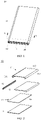
- the electronic device 10 may include an appearance member 11, a first housing 12, a second housing 13, a cover member 14, a circuit board assembly 16, and a conductive member 15.
- the appearance member 11 is a component of the electronic device 10 that is exposed to the outside and that can be directly observed by a user.
- the appearance member 11 may be a component with only mechanical functions, such as a housing.
- the appearance member 11 may alternatively be an electronic component, such as a display screen (which may be referred to as a main screen), and may be specifically a curved surface screen.
- the display screen may include a cover plate and a display layer that are attached to each other.
- the cover plate protects the display layer and may be touched by a user.
- the display layer may be formed through superimposition of a plurality of layers of materials, and the display layer has a plurality of pixels, which can implement display.
- the display screen may further include a circuit structure for driving and controlling the display layer, such as a flexible circuit board, data lines, driving lines, and elements.
- a circuit structure for driving and controlling the display layer such as a flexible circuit board, data lines, driving lines, and elements.
- Such circuit structures are deployed outside the display layer.
- several circuit structures such as data lines, driving lines and/or elements may be integrated in the display layer.
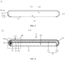
- the appearance member 11 may include a first side portion 111, a main body portion 112, and a second side portion 113, and the main body portion 112 is connected between the first side portion 111 and the second side portion 113.
- the main body portion 112 may have a flat plate-shaped structure or a bent plate-shaped structure with a substantially uniform thickness (the flat plate-shaped structure is used as an example).
- the main body portion 112 may have a flat plate-shaped structure or a bent plate-shaped structure with a nonuniform thickness.
- An outer contour of the main body portion 112 may be approximately rectangular.
- the specific structure of the main body portion 112 is not further limited in this embodiment of this application.
- the structures of the first side portion 111 and the second side portion 113 may be substantially the same or different (the structures being substantially the same is used as an example, and the two side portions may be substantially symmetrically distributed on two sides of the main body portion 112).
- the first side portion 111 and/or the second side portion 113 may have a bent plate-shaped structure with a substantially uniform or nonuniform thickness (a substantially uniform thickness is used as an example).
- the first side portion 111 and the second side portion 113 may each be bent and arched in a direction away from each other, for example, approximately in an arc shape.
- Such a structure connected by the first side portion 111 and the main body portion 112 may be referred to as the first side portion 111 being bent relative to the main body portion 112, that is, transitioning from the flat main body portion 112 to the bent first side portion 111.
- such a structure connected by the second side portion 113 and the main body portion 112 may be referred to as the second side portion 113 being bent relative to the main body portion 112.
- the bending angle of the first side portion 111 and the bending angle of the second side portion 113 may both reach 150° to 180° (including 150° and 180°).
- the bending angle may be defined in the following manner: a tangent line L1 of the first side portion 111 is made at a position in which the first side portion 111 is connected to the main body portion 112, and a tangent line L2 of the first side portion 111 is made at an end portion of the first side portion 111 away from the main body portion 112.
- the tangent line L1 and the tangent line L2 are both rays.
- An angle formed between the tangent line L1 and the tangent line L2 by rotating from the tangent line L1 to the tangent line L2 is referred to as a bending angle.
- the bending angle of the first side portion 111 shown in FIG. 4 may be 180°.
- the bending angle of the second side portion 113 may also be 180°. That is, lengths of the first side portion 111 and the second side portion 113 in a bending direction may both be half of a circumference. Alternatively, the bending angle of the first side portion 111 and the bending angle of the second side portion 113 may be different. In this case, the lengths of the first side portion 111 and the second side portion 113 in the bending direction may be different.
- the bending angle of the first side portion 111 and the bending angle of the second side portion 113 may reach 150° to 180°, and it may be considered that two sides of the appearance member 11 form a large-arc bending structure.
- Such a large-arc bending structure can create a full and expanded appearance effect, which enables the electronic device 10 to provide better appearance experience, and can enhance the sense of holding of a user.
- the first side portion 111, the main body portion 112, and the second side portion 113 may enclose a receiving cavity 11a with an opening, where an opening 11b is formed between an end of the first side portion 111 away from the main body portion 112 and an end of the second side portion 113 away from the main body portion 112.
- the receiving cavity 11a may be approximately C-shaped.
- the receiving cavity narrows at the opening 11b.
- a circumferential length of an inner wall of the receiving cavity 11a at a highest arch is the largest, and a circumferential length d1 at the opening 11b is smaller than the largest circumferential length. The circumferential length of the inner wall of the receiving cavity 11a tends to decrease from the highest arch to the opening 11b.
- the circumferential length may be calculated in the following manner: several planes substantially parallel to the main body portion 112 are respectively intersected with the inner wall of the receiving cavity 11a to obtain several intersection lines. A length of each intersection line may be referred to as a circumferential length of the inner wall of the receiving cavity 11a.
- the bent first side portion 111 may enclose a first receiving space 111a, and the first receiving space 111a serves as an inside space of the first side portion 111.
- the first receiving space 111a may be an approximately semicircular open cavity, and a junction (shown by a vertical dashed line at the tangent line L1 in FIG. 3 ) of the first side portion 111 and the main body portion 112 may be used as a boundary of the first receiving space 111a.
- the first receiving space 111a is a region of the receiving cavity 11a.
- the first receiving space 111a is configured for receiving the first housing 12 (the description is continued below).
- the first receiving space 111a has an inner surface 111b (that is, the inner surface 111b of the first side portion 111).
- the first housing 12 may be approximately semi-cylindrical, and a cross section thereof (a cross section perpendicular to an extending direction thereof) may be approximately semi-circular.
- the first housing 12 is mounted in the first receiving space 111a of the first side portion 111.
- the first housing 12 may be connected to an inner wall of the first receiving space 111a.
- the connection includes that the first housing 12 and the inner wall of the first receiving space 111a are indirectly connected through a medium (such as adhesive and foam), and may further include that the first housing 12 is in direct contact with the inner wall of the first receiving space 111a.
- the first housing 12 is entirely located in the first receiving space 111a, and the first housing 12 substantially just fills the first receiving space 111a. That is, a boundary of the first housing 12 is substantially flush with a boundary of an opening of the first receiving space 111a.
- the first housing 12 is only partially located in the first receiving space 111a and partially located outside the first receiving space 111a; or the first housing 12 is entirely located in the first receiving space 111a, but the boundary of the first housing 12 is retracted within the boundary of the opening of the first receiving space 111a.
- the first housing 12 may include a first anti-collision portion 121 and a support portion 122 that are connected to each other.
- the first anti-collision portion 121 and the support portion 122 may be connected as a whole; or the first anti-collision portion 121 and the support portion 122 may be manufactured separately and then assembled together.
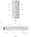
- the first anti-collision portion 121 may be strip-shaped and have a cross-sectional structure that is approximately arcuate plate-shaped. As shown in FIG. 5 , the first anti-collision portion 121 may have a surface 121a that is approximately a semi-cylindrical surface. As shown in FIG. 3 and FIG. 5 , the surface 121a of the first anti-collision portion 121 and the inner surface 111b of the first receiving space 111a are substantially profiled (similar to each other). The surface 121a and the inner surface 111b may be in direct contact. Alternatively, the surface 121a and the inner surface 111b may be indirectly connected through a medium.
- the surface of the surface 121a may be bonded with foam, and the foam may be in contact with the inner surface 111b; or the surface 121a and the inner surface 111b may be bonded by using adhesive.
- the first anti-collision portion 121 may substantially just fill the first receiving space 111a. That is, a boundary of the first anti-collision portion 121 is substantially flush with the boundary of the first receiving space 111a.
- the first anti-collision portion 121 is only partially located in the first receiving space 111a and is partially outside the first receiving space 111a; or the first anti-collision portion 121 is entirely located in the first receiving space 111a, but the boundary of the first anti-collision portion 121 is retracted within the boundary of the opening of the first receiving space 111a.
- the first anti-collision portion 121 having an arcuate bent shape may enclose a second receiving space, and an inner surface of the second receiving space 121b may be approximately a semi-cylindrical surface.
- the second receiving space 121b is configured for receiving the support portion 122, which is described below.
- the first anti-collision portion 121 may be made of a material with a relatively soft texture.
- the material hardness of the first anti-collision portion 121 may be Shore D60 to Shore D90, such as Shore D60, Shore D70, Shore D80, and Shore D90.
- the first anti-collision portion 121 with such material hardness facilitates alleviating the problem of uneven stress on the first side portion 111 (the description is continued below).
- a material modulus of the first anti-collision portion 121 may be 1000 MPa to 15000 MPa (including endpoint values), so that the first anti-collision portion 121 has certain deformation performance, and the problem of uneven stress of the first side portion 111 can be alleviated (the description is continued below).
- Material strength of the anti-collision portion 121 may be 20 MPa to 200 MPa (including endpoint values), so that the first anti-collision portion 121 has suitable structural support performance.
- the material of the first anti-collision portion 121 may be plastic, including but not limited to polybutylene terephthalate (polybutylene terephthalate, PBT) containing 20% glass fiber (glass fiber, GF), polycarbonate (polycarbonate, PC) containing 20% glass fiber, polyamide (polyamide, PA), and polyphenylene sulfide (polyphenylene sulfide, PPS).
- the material of the first anti-collision portion 121 may be a bio-based material (a material obtained by extracting and processing components from animals and plants), a composite material, foam ceramic, Kevlar, nanocellulose, a carbon fiber, and the like.
- the first anti-collision portion 121 cannot transmit electromagnetic waves, and may be, for example, an insulator.
- the support portion 122 may be approximately column-shaped or strip-shaped. As shown in FIG. 5 , the support portion 122 is entirely located in the second receiving space 121b of the first anti-collision portion 121. The support portion 122 may substantially just fill the second receiving space 121b. That is, a boundary of the support portion 122 is substantially just flush with a boundary of an opening of the second receiving space 121b. The shape of the support portion 122 may be adapted to the shape of the second receiving space 121b. The inner surface of the second receiving space 121b may cover the support portion 122. That is, the inner surface of the second receiving space 121b may be substantially seamlessly attached to a surface of the support portion 122.
- the support portion 122 is only partially located in the second receiving space 121b and is partially outside the second receiving space 121b; or the support portion 122 is entirely located in the second receiving space 121b, but the boundary of the support portion 122 is retracted within the boundary of the opening of the second receiving space 121b.
- the support portion 122 may be used as a structural bearing component in the first housing 12 to ensure the structural strength of the first housing 12.
- Material strength of the support portion 122 may be 100 MPa to 500 MPa, such as 100 MPa, 200 MPa, 350 MPa, or 500 MPa.
- the material strength of the support portion 122 has a relatively great impact on the structural strength of the first housing 12, and setting a material modulus of the support portion 122 within the foregoing range can better ensure the structural strength of the first housing 12.
- the material modulus of the support portion 122 may be 40 GPa to 100 GPa, such as 40 GPa, 60 GPa, 80 GPa, or 100 GPa.
- a material toughness (or referred to as elongation at break) of the support portion 122 may be 1% to 20%, such as 1%, 5%, 10%, or 20%.
- the material modulus and material toughness of the support portion 122 also have an impact on the structural strength of the first housing 12. Setting at least one of the two material parameters within the foregoing corresponding range can optimize the structural strength of the first housing 12.
- the material hardness of the support portion 122 may be greater than the material hardness of the first anti-collision portion 121. That is, the texture of the support portion 122 is relatively hard, and the texture of the first anti-collision portion 121 is relatively soft. This enables the support portion 122 to maintain a constant surface shape, which facilitates the support portion 122 in performing a structural bearing function.
- the material of the support portion 122 may be metal, such as aluminum profile (6013, 6063, 5083, 7075, and the like), die-cast aluminum (for example, ADC12), magnesium alloy (for example, AZ91D), copper alloy, or stainless steel (such as 301 and 304).
- the material of the support portion 122 may be ceramic, Kevlar, nanocellulose, a composite material, a carbon fiber, or the like.
- a surface of the support portion 122 facing the first anti-collision portion 121 may form at least one groove 122a.
- FIG. 6 shows two grooves 122a.
- the grooves 122a are spaced apart.
- the groove 122a may be approximately a dovetail groove. That is, as shown in FIG. 5 , a cross-sectional shape of the groove 122a may be approximately a trapezoid, and the trapezoid has a wider bottom edge and a narrower top end.
- a surface of the first anti-collision portion 121 facing the support portion 122 may form at least one protrusion 121c, and a quantity of the protrusions 121c may be the same as a quantity of the grooves 122a.
- the protrusions 121c are spaced apart.
- a shape of the protrusion 121c may be adapted to a shape of the groove 122a. That is, as shown in FIG. 6 , a cross-sectional shape of the protrusion 121c may be approximately a trapezoid, and the protrusion 121c has a narrower root and a wider top.
- the protrusions 121c are fitted with the grooves 122a, or referred to as that the protrusions 121c are inserted into the grooves 122a to form a connection.
- the dovetail groove-shaped grooves 122a enable the protrusions 121c to be reliably fitted with the grooves 122a, and ensure that the first anti-collision portion 121 and the support portion 122 are firmly connected.
- the shape of the groove 122a on the support portion 122 and the shape of the protrusion 121c on the first anti-collision portion 121 in FIG. 6 are merely examples, and this embodiment of this application is not limited thereto. For example, as shown in FIG. 7 (FIG.
- the surface of the support portion 122 may be further provided with grooves in other shapes, such as a groove 122c that is approximately T-shaped, and a groove 122b that is approximately arc-shaped (which may be a semicircle, a superior arc, or an inferior arc). There may be at least one groove 122a, groove 122b, and groove 122c.
- a protrusion 121d on the first anti-collision portion 121 has a shape adapted to the groove 122b, and the protrusion 121d is fitted with the groove 122b; and a protrusion 121e on the first anti-collision portion 121 has a shape adapted to the groove 122c, and the protrusion 121e is fitted with the groove 122c.
- the support portion 122 in FIG. 7 has the groove 122a, the groove 122b, and the groove 122c at the same time, and the first anti-collision portion 121 has the protrusion 121c, the protrusion 121d, and the protrusion 121e at the same time.
- at least one type of groove may be provided on the support portion 122, and at least one type of protrusion may be formed on the first anti-collision portion 121.
- the positions of the groove and the protrusion may be interchanged. That is, a groove may be formed on the first anti-collision portion 121, and a protrusion may be formed on the support portion 122, where the protrusion is fitted with the groove. Therefore, in this embodiment of this application, it may be considered that a first fitting portion is formed on the first anti-collision portion 121, a second fitting portion is formed on the support portion 122, and one of the first fitting portion and the second fitting portion is a groove and the other is a protrusion.
- the first anti-collision portion 121 and the support portion 122 may alternatively be connected through other structures or in other manners, which is not limited to the fitting between protrusions and grooves.
- the first anti-collision portion 121 and the support portion 122 may be manufactured through an integrated process.
- the first anti-collision portion 121 and the support portion 122 may be formed through an in-mold injection process.
- the support portion 122 may be placed into a mold cavity of an injection molding device to make molten plastic adhere to the surface of the support portion 122.
- the plastic and the support portion 122 may be reliably combined through processes such as pressure holding and cooling, and finally the first housing 12 is obtained.
- the plastic part forms the first anti-collision portion 121, and the first anti-collision portion 121 and the support portion 122 are connected as a whole.
- the protrusions on the first anti-collision portion 121 may be formed naturally during the adhesion of the molten plastic.
- the foregoing formation through the in-mold injection molding process is only an example, and the first housing 12 may alternatively be manufactured through other suitable processes.
- a nano-injection process may be used, or the nano-injection process and the in-mold injection process may be used to form the integrated first housing 12.
- the first anti-collision portion 121 and the support portion 122 may be manufactured by using suitable processes respectively, and are then assembled.
- the support portion 122 may be inserted into the second receiving space 121b of the first anti-collision portion 121 in a manner similar to pushing a drawer.
- the second housing 13 is mounted in the receiving cavity 11a of the appearance member 11, and the second housing 13 may be in direct contact with the inner wall of the receiving cavity 11a.
- the second housing 13 may be indirectly connected to the inner wall of the receiving cavity 11a through a medium.
- the surface of the second housing 13 may be bonded with foam, and the foam may be in contact with the inner wall of the receiving cavity 11a; or the second housing 13 and the inner wall of the receiving cavity 11a may be bonded by using adhesive.
- the first housing 12 and the second housing 13 are adjacent to each other side by side. For example, in the perspective of FIG.
- the first housing 12 and the second housing 13 are adjacent to each other side by side in a left-right direction, instead of being stacked in an up-down direction.
- the first housing 12 and the second housing 13 may be fixedly connected through, for example, bonding, clamping by using a buckle structure, or a connection by using a connecting member (for example, a screw).
- the first housing 12 and the second housing 13 may not form a connection, and may be placed side by side with a gap maintained in between. The gap may be relatively small to ensure reliable support of the first housing and the second housing for the appearance member 11.
- the shape of the second housing 13 may be adapted to the shape of the receiving cavity 11a.
- the second housing 13 may include a first part 131 and a second part 132, and the first part 131 and the second part 132 may be connected as a whole or assembled together.
- the first part 131 may be approximately plate-shaped, and may be substantially profiled with the main body portion 112 of the appearance member 11, and the first part 131 is connected to the main body portion 112.
- the second part 132 may be approximately in a semi-cylindrical shape, and a cylindrical side surface of the second part 132 may be approximately tangent to a surface of the first part 131 facing the main body portion 112.
- the second part 132 may be further considered as a wall structure protruding toward a side of the first part 131 (for example, a lower side of the first part 131 in FIG. 4 ).
- the second part 132 may be substantially profiled with the second side portion 113.
- the second part 132 may be substantially sticked to the surface of the second side portion 113, and the second part 132 is connected to the second side portion 113.
- the first housing 12 is located in the first receiving space 111a of the receiving cavity 11a of the appearance member 11, and the second housing 13 substantially occupies regions in the receiving cavity 11a other than the first receiving space 111a.
- Such a design makes a joining line between the second housing 13 and the first housing 12 (that is, a dividing line between the second housing and the first housing) close to the first side portion 111 of the appearance member 11, and a relatively large and continuous surface of the first part 131 of the second housing 13 may be used to support the main body portion 112 of the appearance member 11, to ensure the reliability of the main body portion 112.
- the relatively large and continuous surface of the first part 131 can ensure relatively high flatness, and can be more precisely fitted with the main body portion 112 that is also in a flat plate shape, thereby ensuring the reliability of the main body portion 112.
- the size of the first housing 12 may be increased, and the first housing 12 may include a part located in the first receiving space 111a and a part outside the first receiving space 111a.
- the part of the first housing 12 located outside the first receiving space 111a and the first part 131 of the second housing 13 jointly support the main body portion 112 of the appearance member 11.
- the second housing 13 may also include a first anti-collision portion and a support portion.
- the second part 132 of the second housing 13 may include a first anti-collision portion and a support portion connected to each other.
- the first anti-collision portion may be connected to the second side portion 113.
- the support portion may include a part supporting the main body portion 112 and a part supporting the second side portion 113.
- the part supporting the main body portion 112 may be connected to the main body portion 112.
- the part supporting the second side portion 113 is connected to the first anti-collision portion, and the first anti-collision portion may separate the part supporting the second side portion 113 from the second side portion 113.
- Such a second housing 13 may be considered to have an anti-collision design.
- the material selection and material parameters of the first anti-collision portion of the second housing 13 may be the same as those of the first anti-collision portion 121 of the first housing 12.
- the material selection and material parameters of the support portion of the second housing 13 may be the same as those of the support portion 122 of the first housing 12. Details are not described herein again.
- the second housing 13 with the anti-collision design is an example, and this embodiment of this application is not limited thereto actually.
- the second housing 13 may alternatively include a support portion but no first anti-collision portion.
- the first housing 12 and the second housing 13 may be collectively referred to as housings.
- the housings may be, for example, middle frames of the electronic device 10, and the first housing 12 and the second housing 13 are each a middle frame.
- the electronic device 10 in Embodiment 1 includes a first housing 12 and a second housing 13, and this is only an example. This embodiment of this application is not limited thereto actually.
- the electronic device may further include another housing, and the another housing is adjacent to the first housing 12 and the second housing 13 side by side, which are all mounted in the receiving cavity 11a of the appearance member 11.
- the first housing 12, the second housing 13, and the appearance member 11 may be assembled according to the following process:
- the first housing 12 with a relatively small size may be first placed from the opening 11b of the receiving cavity 11a into the first receiving space 111a, the second housing 13 is maintained in an inclined posture, and then one end of the second housing 13 (which is referred to as a first end) is placed from the 11b into a position in the receiving cavity 11a corresponding to the second side portion 113.
- the other end of the second housing 13 (which is referred to as a second end, the second end being opposite to the first end) has not entered the receiving cavity 11a.
- the second end is placed into the receiving cavity 11a, and finally the second housing 13 is entirely received in the receiving cavity 11a.
- the first anti-collision portion 121 When the first anti-collision portion 121 is fitted with the inner wall of the first receiving space 111a, because an outer layer of the first housing 12 is the first anti-collision portion 121 with a relatively soft texture, collision of the first anti-collision portion 121 on the first side portion 111 is relatively gentle, and the first side portion 111 receives relatively small impact, so that the first side portion 111 is not prone to damage. Similarly, the second housing 13 with the anti-collision design can also make the second side portion 113 not prone to damage. Therefore, the reliability of the appearance member 11 is improved.
- the first housing 12 probably cannot be closely adhered to the inner wall of the first receiving space 111a, and a part of the first housing 12 may form point contact or line contact with the inner wall of the first receiving space 111a.
- an outer layer of the first housing 12 is the first anti-collision portion 121 with a relatively soft texture, even if the first anti-collision portion 121 forms point contact or line contact with the inner wall of the first receiving space 111a, the inner wall of the first receiving space 111a is not severely extruded and hit, which can avoid concentration of stress generated on the inner wall of the first receiving space 111a, and reduce the risk of damage to the first side portion 111.
- an outer layer of the second housing 13 has the first anti-collision portion, the risk of damage to the second side portion 113 can also be reduced. Based on this, the reliability of the appearance member 11 is improved.
- the first housing 12 and the second housing 13 can be separately mounted in the receiving cavity 11a of the appearance member 11.
- Such a separate housing design can meet the assembly requirements of a relatively narrow opening 11b between the first side portion 111 and the second side portion 113 in the appearance member 11, and a relatively large overall size of the housings, and overcomes the problem of assembling the conventional housing and the appearance member 11 with large-arc bending.
- the circuit board assembly 16 is located in the receiving cavity 11a and may be fixed on a side of the second housing 13 facing away from the appearance member 11.
- the circuit board assembly 16 may be located in a space enclosed by the first part 131 and the second part 132. An edge of the circuit board assembly 16 may be close to the first housing 12.
- the circuit board assembly 16 can implement electrical control of the electronic device 10, so that the electronic device 10 has electrical performance.
- the circuit board assembly 16 may include a circuit board and a circuit deployed on the circuit board.
- the circuit may include a radio frequency circuit that may be configured to convert a baseband signal into a radio frequency signal.
- Aground pole may be further deployed on the circuit board.
- the ground pole may be a conductor, and may be used as a zero potential reference point of the circuit board.
- the conductive member 15 may be fixed on the circuit board assembly 16, for example, may be fixed on a side of the circuit board assembly 16 facing away from the second housing 13.
- the conductive member 15 may be mounted on the edge of the circuit board assembly 16, to facilitate a connection of the conductive member 15 with the support portion 122 of the first housing 12.
- the connection between the conductive member 15 and the support portion 122 may be a non-fixed connection, such as contact; or may be a fixed connection, such as welding, and clamping.
- the conductive member 15 has conductive performance, and may be, for example, made of a metal material (such as copper). This embodiment of this application does not limit the structure of the conductive member 15.
- the conductive member 15 may be an elastic piece.
- the conductive member 15 may be used as a feeding component (which is described below), or a grounding component.
- the support portion 122 may be used as an antenna radiator.
- the support portion 122 may be electrically connected to the radio frequency circuit of the circuit board assembly 16 through the conductive member 15, to receive a radio frequency signal, convert the radio frequency signal into an electromagnetic wave signal, and then radiate the electromagnetic wave signal.
- the conductive member 15 may be used as a feeding component to feed the radio frequency signal into the support portion 122.
- the support portion 122 sends electromagnetic wave signals to implement antenna output is used.
- the support portion 122 may alternatively receive electromagnetic wave signals to implement antenna input.
- the support portion 122 may be used as an antenna radiator, and the support portion 122 may be electrically connected to the radio frequency circuit in other manners.
- the conductive member 15 may be used as a grounding component to implement the grounding of the support portion 122.
- the support portion 122 can function as both structural support and an antenna radiator, which may avoid additional arrangement of an antenna radiator, and simplify the product structure.
- the appearance member 11 when the appearance member 11 is an electronic component, the appearance member 11 may interfere with an antenna signal.
- the first anti-collision portion 121 between the appearance member 11 and the support portion 122 cannot transmit electromagnetic waves, that is, the first anti-collision portion 121 that does not interfere with the antenna signal can separate the support portion 122 from the appearance member 11 that may interfere with the antenna signal, an antenna clearance region required by the support portion 122 can be provided to ensure the radiation and receiving performance of the support portion 122.
- the support portion 122 may not serve as an antenna radiator.
- the cover member 14 may be approximately in a plate shape, for example, a flat plate or a bent plate. As shown in FIG. 3 , the cover member 14 may be mounted at the opening 11b of the receiving cavity 11a to close the receiving cavity 11a.
- the cover member 14 may be a component with only mechanical functions; or the cover member 14 may be an electronic component, such as a display screen (which may be referred to as a sub screen). The meaning of the display screen is the same as that described above, and the details are not repeated herein.
- the cover member 14 is also a display screen, the electronic device 10 can implement 360-degree omnidirectional surround display.
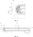
- a first housing 22 of an electronic device 20 may include a first anti-collision portion 221, a support portion 222, and a second anti-collision portion 223, which may be connected as a whole, or may be manufactured separately and then assembled together.
- the first anti-collision portion 221 is connected to the first side portion 111 of the appearance member 11.
- the support portion 222 is located between the first anti-collision portion 221 and the second anti-collision portion 223.
- the structure of the first anti-collision portion 221 may be similar to the structure of the first anti-collision portion 121 described above.
- the first anti-collision portion 221 may have a cross-sectional structure that is approximately arcuate plate-shaped.
- the first anti-collision portion 221 and the first receiving space 111a are substantially profiled, and the first anti-collision portion 221 may be connected to the inner wall of the first receiving space 111a, for example, bonded by using adhesive; or a surface of the first anti-collision portion 221 may be bonded by using foam, and the foam is in contact with the inner wall of the first receiving space 111a.
- the first anti-collision portion 221 may also enclose a second receiving space.
- two ends of the first anti-collision portion 221 in a circumferential direction may be retracted within the boundary of the first receiving space 111a (in FIG. 9 , two relatively long vertical dashed lines are used to represent the boundary of the first receiving space 111a, and this is only schematic for clear expression).
- one end of the first anti-collision portion 221 in the circumferential direction is retracted within the boundary of the first receiving space 111a, and the other end in the circumferential direction is substantially flush with the boundary of the first receiving space 111a or exceeds the boundary of the first receiving space 111a.
- the two ends of the first anti-collision portion 221 in the circumferential direction may both be substantially flush with the boundary of the first receiving space 111a.
- the material selection and material parameters of the first anti-collision portion 221 may be the same as those of the first anti-collision portion 121, and the details are not repeated herein.
- the structure of the support portion 222 is similar to the structure of the first anti-collision portion 121 described above, and the support portion 222 may have a cross-sectional structure that is approximately arcuate plate-shaped.
- a boundary of the support portion 222 may be substantially just flush with the boundary of the first receiving space 111a. The difference is that two ends of the support portion 222 in the circumferential direction may both exceed the corresponding boundary of the first anti-collision portion 221, or the two ends of the first anti-collision portion 221 in the circumferential direction may both be retracted to the corresponding boundary of the support portion 222. This enables the first anti-collision portion 221 to avoid the first side portion 111 of the appearance member 11.
- the first anti-collision portion 221 can be prevented from colliding or hitting the transition region between the first side portion 111 and the main body portion 112, thereby improving the reliability of the appearance member 11.
- connection manner of the support portion 222 and the first anti-collision portion 221 may be the same as that described in Embodiment 1.
- the material selection and material parameters of the support portion 222 may be the same as those of the support portion 122 in Embodiment 1. Details are not described herein again.
- the structure of the second anti-collision portion 223 may be similar to that of the support portion 122 described above.
- the second anti-collision portion 223 may be approximately in a semi-cylindrical shape.
- a semi-cylindrical surface of the second anti-collision portion 223 may be connected to the support portion 222.
- the connection manner of the second anti-collision portion 223 and the support portion 222 may be the same as that of the first anti-collision portion 221 and the support portion 222, and the details are not repeated herein.
- the first housing 22 may have no second anti-collision portion 223.
- the material selection and material parameters of the second anti-collision portion 223 may be the same as those of the first anti-collision portion 221, and the details are not repeated herein.
- a material hardness of the second anti-collision portion 223 and a material hardness of the first anti-collision portion 221 may be different, but are both less than a material hardness of the support portion 222. Because the texture of the second anti-collision portion 223 is relatively soft, collision damage to a component mounted in the appearance member 11 can be avoided, and the component may be, for example, a component deployed on the circuit board assembly 16.
- Embodiment 2 may also have the technical effects of Embodiment 1, such as providing the appearance member 11 with relatively high reliability; overcoming the problem of assembling the conventional housing and the appearance member 11 with large-arc bending; using the support portion 222 as an antenna radiator and ensuring the radiation and receiving performance of the support portion 222; and implementing 360-degree omnidirectional surround display.
- Embodiment 2 by making the avoidance design for the first anti-collision portion 221, the first anti-collision portion 221 can be prevented from colliding or hitting the transition region between the first side portion 111 and the cover member 14, or the transition region between the first side portion 111 and the main body portion 112, thereby enhancing the reliability of the appearance member 11, and avoiding collision damage to a component mounted in the appearance member 11.
- a first housing 32 of an electronic device 30 of Embodiment 3 may include a first anti-collision portion 321 and two support portions 322.
- the first anti-collision portion 321 of Embodiment 3 may include a connection portion 3211 and a separation portion 3212.
- connection portion 3211 may be similar to that of the first anti-collision portion 121 of Embodiment 1.
- the connection portion 3211 may have a cross-sectional structure that is approximately arcuate plate-shaped.
- the connection portion 3211 may be profiled with the first side portion 111.
- Two ends of the connection portion 3211 in a circumferential direction (a direction extending along an arc) may both be substantially flush with the boundary of the first receiving space 111a (in FIG. 9 , two relatively long vertical dashed lines are used to represent the boundary of the first receiving space 111a, and this is only schematic for clear expression) of the first side portion 111.
- the connection portion 3211 may be in direct contact with the inner wall of the first receiving space 111a.
- connection portion 3211 may be indirectly connected to the inner wall of the first receiving space 111a through a medium.
- a surface of the connection portion 3211 may be bonded with foam, and the foam may be in contact with the inner wall of the first receiving space 111a; or the surface of the connection portion 3211 and the inner wall of the first receiving space 111a may be bonded by using adhesive.
- the connection portion 3211 may enclose a second receiving space 321a.
- the separation portion 3212 may have a cross-sectional structure that is approximately rectangular.
- the separation portion 3212 is connected to an inner wall of the second receiving space 321a.
- the separation portion 3212 divides the second receiving space 321a into a region C1 and a region C2.
- the separation portion 3212 may, for example, substantially divide the second receiving space 321a equally, so that shapes and sizes of the region C1 and the region C2 are substantially equal, for example, an inner wall of the region C1 and an inner wall of the region C2 are both approximately a quarter of an arc surface.
- a position of the separation portion 3212 in the second receiving space 321a may be flexibly set as required, and the shapes and sizes of the region C1 and the region C2 may be adjusted correspondingly.
- connection portion 3211 in the circumferential direction may be retracted within the corresponding boundary of the first receiving space 111a. This is the same avoidance design as described in Embodiment 2, which can improve the reliability of the appearance member 11.
- the material selection and material parameters of the first anti-collision portion 321 of Embodiment 3 may be the same as those of the first anti-collision portion 121 of Embodiment 1, and the details are not repeated herein.
- the region C1 and the region C2 may be each provided with a support portion 322.
- the support portion 322 in the region C1 may have a structure adapted to the region C1, and may substantially fill the region C1.
- the support portion 322 in the region C2 may have a structure adapted to the region C2, and may substantially fill the region C2.
- the connection manner of the two support portions 322 and the first anti-collision portion 121 may be the same as that described in Embodiment 1, and the details are not repeated herein.
- the support portion 322 in the region C1 is partially located in the region C1, and may be partially located outside the region C1.
- the support portion 322 in the region C2 is partially located in the region C1, and may be partially located outside the region C1.
- the material selection and material parameters of the two support portions 322 may be the same as those of the support portion 122 in Embodiment 1. Details are not described herein again. Alternatively, the materials of the two support portions 322 may be different, but may be both determined from the range of materials that may be selected for the support portion 122 in Embodiment 1. The material parameters of the two support portions 322 may be different, but may be both determined from the range of material parameters that may be selected for the support portion 122 in Embodiment 1.
- Each support portion 322 may be used as an independent antenna radiator. Because the two support portions 322 are separated by the separation portion 3212, the two support portions do not electromagnetically interfere with each other. Alternatively, only one of the support portions 322 may be an antenna radiator, and the other support portion 322 may be used as a purely mechanical component without an electromagnetic wave transmission function.
- a quantity of separation portions 3212 may be n, where n is greater than or equal to 2.
- the n separation portions 3212 may divide the second receiving space 321a of the connection portion 3211 into, for example, n+1 regions, and each region may be provided with a support portion 322.
- Embodiment 3 may also have the technical effects of Embodiment 1, such as providing the appearance member 11 with relatively high reliability; overcoming the problem of assembling the conventional housing and the appearance member 11 with large-arc bending; using one or two support portions 322 as antenna radiators and ensuring the radiation and receiving performance of the antenna radiators; and implementing 360-degree omnidirectional surround display.
- a first anti-collision portion 421 of a first housing 42 of an electronic device 40 may include a connection portion 4211 and a separation portion 3212.
- one end (for example, an end close to the cover member 14) of the connection portion 4211 in a circumferential direction (a direction extending along an arc) may be retracted within the corresponding boundary of the first receiving space 111a (in FIG. 13 , two relatively long vertical dashed lines are used to represent the boundary of the first receiving space 111a, and this is only schematic for clear expression). That is, this end of the connection portion 4211 makes avoidance relative to the first side portion 111.
- connection portion 4211 with the avoidance may correspond to the region C2. There is a gap between the separation portion 322 located in the region C2 and the first side portion 111. With such an avoidance design, the connection portion 4211 can be prevented from colliding or hitting the transition region between the first side portion 111 and the cover member 14, thereby improving the reliability of the appearance member 11. It may be understood that, according to product requirements, the other end (for example, an end close to the main body portion 112) of the connection portion 4211 in the circumferential direction may also be retracted within the corresponding boundary of the first receiving space 111a.
- Embodiment 4 may also have the technical effects of Embodiment 3, such as providing the appearance member 11 with relatively high reliability; overcoming the problem of assembling the conventional housing and the appearance member 11 with large-arc bending; using one or two support portions 322 as antenna radiators and ensuring the radiation and receiving performance of the antenna radiators; and implementing 360-degree omnidirectional surround display.
- the first anti-collision portion 421 can be prevented from colliding or hitting the transition region between the first side portion 111 and the cover member 14, and/or the transition region between the first side portion 111 and the main body portion 112, thereby enhancing the reliability of the appearance member 11.
- an appearance member 51 of an electronic device 50 may include a first side portion 511, a main body portion 112, and a second side portion 513.
- the appearance member 51 of Embodiment 5 may be approximately in a box shape.
- the first side portion 511 may include a flat portion 5111 and a flat portion 5112, both of which may have a substantially flat plate-shaped structure.
- the flat portion 5111 and the flat portion 5112 are connected to form an included angle, and the included angle may be, for example, approximately 90 degrees.
- the flat portion 5111 may be connected to the main body portion 112 to form an included angle, and the included angle may be, for example, approximately 90 degrees.
- the second side portion 513 may have substantially the same structure as the first side portion 511.
- a first receiving space 511a enclosed by the first side portion 511 may be approximately square.
- a receiving cavity 51a enclosed by the appearance member 51 narrows at an opening 51b.
- the first side portion 511 may include one flat portion or at least three flat portions.
- An included angle between a flat portion and the main body portion 112 and an included angle between flat portions may be both set according to product requirements, and are not limited to approximately 90 degrees.
- a shape of the first receiving space 511a enclosed by the first side portion 511 is also adjusted.
- a first anti-collision portion 521 of a first housing 52 may include a connection portion 5211 and a separation portion 3212.
- the shape of the connection portion 5211 of Embodiment 5 may be adapted to the shape of the first receiving space 511a of the first side portion 511.
- the connection portion 5211 may have a cross-sectional structure that is approximately box-shaped.
- the appearance of the electronic device 50 of Embodiment 5 is relatively tough, which can meet requirements of some application scenarios, such as an application scenario in which the electronic device 50 is used as an outdoor display device.
- the solution of Embodiment 5 may also have the technical effects of Embodiment 3, such as providing the appearance member 51 with relatively high reliability; overcoming the problem of assembling the conventional housing and the appearance member 51 with large-arc bending; using one or two support portions 322 as antenna radiators and ensuring the radiation and receiving performance of the antenna radiators; and implementing 360-degree omnidirectional surround display.
- the designs in the foregoing embodiments may be combined according to product requirements.
- structures on different cross sections of the first housing may be different, for example, structures on two cross sections may be respectively as shown in any two of FIG. 5 , FIG. 9 , FIG. 11 , and FIG. 13 , or structures on three cross sections may be respectively as shown in any three of FIG. 5 , FIG. 9 , FIG. 11 , and FIG. 13 , and so on.
- One first housing has only one cross-sectional structure, and different first housings have different cross-sectional structures.
- the first housing is an integral component, each section of the first housing has only one cross-sectional structure, and different sections have different cross-sectional structures.
Landscapes
- Engineering & Computer Science (AREA)
- Signal Processing (AREA)
- Casings For Electric Apparatus (AREA)
Abstract
Description
- This application claims priority to
Chinese Patent Application No. 2020111376837, entitled "ELECTRONIC DEVICE" filed with the China National Intellectual Property Administration on October 22, 2020 - This application relates to the field of terminal devices, and in particular, to an electronic device.
- To pursue a simple and consistent appearance, an electronic device is usually designed with an integrated appearance member. The appearance member has a main body and side walls, and the side walls are bent relative to the main body. A housing needs to be amounted on an inner side of the appearance member to support the appearance member. Due to such a bending transition structure of the appearance member, when the housing and the appearance member are assembled, the housing may easily collide with the side walls. This causes excessive stress on the side walls, and damage is prone to occur, consequently reducing the reliability of the appearance member.
- The technical solution of this application provides an electronic device, which can resolve a problem of uneven stress on an appearance member due to collision when a housing and the appearance member are assembled.
- The electronic device according to the technical solution of this application includes: an appearance member, a first housing, and a second housing. The appearance member includes a main body portion, and a first side portion and a second side portion respectively connected to opposite sides of the main body portion, the first side portion and the second side portion are both bent relative to the main body portion, the first side portion, the main body portion, and the second side portion enclose a receiving cavity, and the first side portion and the second side portion are spaced opposite to each other to form an opening of the receiving cavity. The first housing is located in the receiving cavity and includes a first anti-collision portion and a support portion connected to the first anti-collision portion, the first anti-collision portion is connected to the first side portion and located between the first side portion and the support portion, and a material hardness of the first anti-collision portion is less than a material hardness of the support portion. The second housing is located in the receiving cavity; and in a direction from the first side portion to the second side portion, the first housing and the second housing are adjacent to each other side by side, and the second housing is connected to the main body portion and the second side portion.
- In the technical solution of this application, the appearance member is a component of the electronic device that is exposed to the outside and that can be directly observed by a user. The appearance member may be a component with only mechanical functions, such as a housing; or the appearance member may be an electronic component, such as a display screen (which may be referred to as a main screen). The main body portion may be a plate-shaped structure with a substantially uniform or nonuniform thickness. The structures of the first side portion and the second side portion may be substantially the same or different. The first side portion and/or the second side portion may be a plate-shaped structure with a substantially uniform or nonuniform thickness. Taking the first side portion as an example, the first side portion may have a flat plate structure or be formed by at least two flat plate structures connected end to end, and the first side portion may be connected to the main body portion at an included angle. Alternatively, the first side portion may have a bent plate structure (for example, an approximately arcuate plate), and the first side portion may be transitioned with the main body portion based on bending. Such a structure connected by the first side portion and the main body portion may be referred to as the first side portion being bent relative to the main body portion. That is, a path transitioned from the main body portion to the first side portion has a bending tendency.
- In the technical solution of this application, the first housing and the second housing are adjacent to each other side by side, instead of being stacked in a thickness direction of the electronic device. The first housing and the second housing jointly support the appearance member. The first anti-collision portion of the first housing separates the support portion from the first side portion, the first anti-collision portion is in contact with and connected to the first side portion, and the support portion is not in contact with or connected to the first side portion. The material hardness of the first anti-collision portion is less than the material hardness of the support portion. That is, the texture of the first anti-collision portion is relatively soft, and the texture of the support portion is relatively hard. The support portion is mainly configured to ensure structural strength of the first housing, so that the first housing can better support the first side portion, and the hardness of the support portion may be set based on this.
- When the first housing is fitted with an inner wall of the first side portion, because the first anti-collision portion has a relatively soft texture, collision of the first anti-collision portion on the first side portion is relatively gentle, and the first side portion receives relatively small impact, so that the first side portion is not prone to damage, thereby improving the reliability of the appearance member. Moreover, considering the limitation of manufacturing accuracy and/or assembly accuracy, the first housing probably cannot be closely adhered to the inner wall of the first side portion, and a part of the first housing may form point contact or line contact with the inner wall of the first side portion. However, because an outer layer of the first housing is the first anti-collision portion with a relatively soft texture, even if the first anti-collision portion forms point contact or line contact with the inner wall of the first side portion, the inner wall of the first side portion is not severely extruded and hit, which can avoid concentration of stress generated on the inner wall of the first side portion, and reduce the risk of damage to the first side portion. Based on this, the reliability of the appearance member is improved.
- In an implementation, the first side portion is bent and encloses a first receiving space, and at least part of the first anti-collision portion is located in the first receiving space. In this implementation, the first side portion may have a bent plate-shaped structure; or may be a plate-shaped structure formed by several flat-plate structures connected end to end, where adjacent flat-plate structures form an included angle. The first receiving space may have a corresponding shape. The first anti-collision portion may substantially just fill the first receiving space, that is, a boundary of the first anti-collision portion is substantially flush with a boundary of the first receiving space; or the first anti-collision portion is only partially located in the first receiving space, and is partially outside the first receiving space; or the first anti-collision portion is entirely located in the first receiving space, but the boundary of the first anti-collision portion is retracted within a boundary of an opening of the first receiving space. In the case of limited manufacturing accuracy and/or assembly accuracy, the bent first side portion may be prone to impact, extrusion, and hitting when fitted with the first housing. However, because the first anti-collision portion with a relatively soft texture is designed in this implementation, the impact, extrusion, and hitting on the first side portion can be reduced, concentration of stress generated on the inner wall of the first side portion can be avoided, and the risk of damage to the first side portion can be reduced, so that the reliability of the appearance member is improved.
- In an implementation, the first anti-collision portion encloses a second receiving space, and at least part of the support portion is located in the second receiving space. In this implementation, the support portion may substantially just fill the second receiving space, that is, a boundary of the support portion is substantially just flush with a boundary of an opening of the second receiving space; or the support portion may be only partially located in the second receiving space, and may be partially outside the second receiving space; or the support portion may be entirely located in the second receiving space, but the boundary of the support portion is retracted within the boundary of the opening of the second receiving space. The support portion may have a shape adapted to the second receiving space. Such a design of the first anti-collision portion and the support portion can support the first side portion well, and ensure the effect of anti-collision protection for the first side portion.
- In an implementation, the support portion is located in the second receiving space, and the support portion fills the second receiving space. That is, the boundary of the support portion is substantially flush with the boundary of the second receiving space. Such a design of the support portion enables the first housing to support the first side portion well, and further makes the structure of the first housing compact, which facilitates the assembly of the first housing.
- In an implementation, the first anti-collision portion includes a connection portion and a separation portion; the connection portion is connected to the first side portion, and the connection portion is profiled with the first side portion and encloses a second receiving space; the separation portion is connected to an inner wall of the second receiving space, and divides the second receiving space into different regions; and each of the regions is provided with the support portion, and at least part of the support portion is located in the region. In this implementation, a shape of the connection portion of the first anti-collision portion may be similar to that of the first side portion. The separation portion is located on a side of the connection portion away from the first side portion. There may be n separation portions, where n is a natural number greater than or equal to 2. The n separation portions may divide the second receiving space of the connection portion into n+1 regions, and each region may be provided with a support portion. A single support portion may substantially just fill a single region, that is, a boundary of the support portion is substantially just flush with a boundary of an opening of the region; or the support portion may be only partially located in the region, and may be partially outside the region; or the support portion may be entirely located in the region, but the boundary of the support portion is retracted within the boundary of the opening of the region. The support portion may have a shape adapted to the region. Such a design of the first anti-collision portion and the support portion enables the first housing to support the first side portion well, and ensures the effect of anti-collision protection for the first side portion.
- In an implementation, the support portion is located in the region, and the support portion fills the region. In this implementation, the support portion in each region can fill the region. That is, the boundary of the support portion is substantially flush with the boundary of the region. Such a design of the support portion enables the first housing to support the first side portion well, and further makes the structure of the first housing compact, which facilitates the assembly of the first housing.
- In an implementation, the first housing includes a second anti-collision portion, the second anti-collision portion is connected to a side of the support portion facing away from the first side portion, and a material hardness of the second anti-collision portion is less than the material hardness of the support portion. In this implementation, the support portion may be sandwiched between the first anti-collision portion and the second anti-collision portion. The texture of the second anti-collision portion is relatively soft, which can avoid collision damage to a component mounted in the appearance member. The size relationship between the material hardness of the second anti-collision portion and the material hardness of the first anti-collision portion is not limited, and the two material hardnesses may be equal or different.
- In an implementation, a surface of the first anti-collision portion is provided with at least one first fitting portion spaced apart, a surface of the support portion is provided with at least one second fitting portion spaced apart, and the at least one second fitting portion is connected to the at least one first fitting portion one by one, where one of the first fitting portion and the second fitting portion is a groove and the other is a protrusion, and the protrusion is inserted into the groove to form a connection. In this implementation, the "one by one connection" refers to a one-to-one connection. That is, one first fitting portion is correspondingly connected to one second fitting portion. Such a connection structure is easy to manufacture, and can ensure the connection strength between the first anti-collision portion and the support portion, thereby ensuring that the first housing can support the first side portion well, and ensuring the effect of anti-collision protection for the first side portion.
- In an implementation, the first anti-collision portion and the support portion are connected as a whole. In this implementation, the first housing may be manufactured through an integrated process, such as an in-mold injection process, a nano-injection process, or both the nano-injection process and the in-mold injection process. The integrated first housing has relatively high dimensional accuracy, which helps ensure the assembly accuracy, facilitates the first housing in supporting the first side portion well, and ensures the effect of anti-collision protection for the first side portion.
- In an implementation, the receiving cavity narrows at the opening, an end of the first housing away from the second housing is connected to the first side portion, and an end of the second housing away from the first housing is connected to the second side portion. In this implementation, a circumferential length of an inner wall of the receiving cavity at a highest arch is the largest, and a circumferential length at the opening is smaller than the largest circumferential length. The circumferential length of the inner wall of the receiving cavity tends to decrease from the highest arch to the opening. The circumferential length may be calculated in the following manner: several planes substantially parallel to the main body portion are respectively intersected with the inner wall of the receiving cavity to obtain several intersection lines. A length of each intersection line may be referred to as a circumferential length of the inner wall of the receiving cavity. The first housing and the second housing substantially fill the receiving cavity, and jointly support the appearance member with the narrowing inner cavity. The appearance member with the narrowing inner cavity may be prone to impact, extrusion, and hitting when fitted with the first housing. However, because the first anti-collision portion with a relatively soft texture is designed in this implementation, the impact, extrusion, and hitting on the first side portion can be reduced, concentration of stress generated on the inner wall of the first side portion can be avoided, and the risk of damage to the first side portion can be reduced, so that the reliability of the appearance member is improved.
- In an implementation, the first side portion and the second side portion are both arcuate, and are both arched in a direction away from each other. Such an arcuate bent structure can create a full and expanded appearance effect, which enables the electronic device to provide better appearance experience, and can enhance the sense of holding of a user. In addition, the appearance member with the arcuate bent structure may be prone to impact, extrusion, and hitting when fitted with the first housing. However, because the first anti-collision portion with a relatively soft texture is designed in this implementation, the impact, extrusion, and hitting on the first side portion can be reduced, concentration of stress generated on the inner wall of the first side portion can be avoided, and the risk of damage to the first side portion can be reduced, so that the reliability of the appearance member is improved.
- In an implementation, a bending angle of the first side portion is 90° to 180°; and/or, a bending angle of the second side portion is 90° to 180°. In this implementation, a tangent line L1 of the first side portion is made at a position in which the first side portion is connected to the main body portion, and a tangent line L2 of the first side portion is made at an end portion of the first side portion away from the main body portion. The tangent line L1 and the tangent line L2 are both rays. An angle formed between the tangent line L1 and the tangent line L2 by rotating from the tangent line L1 to the tangent line L2 is referred to as a bending angle. The bending angles of the first side portion and the second side portion are set independently, and may be the same or different. Setting the bending angles within the range can enable the electronic device to provide better appearance experience and enhance the sense of holding of a user. In addition, by designing the first anti-collision portion with a relatively soft texture, the reliability of the appearance member with such bending angles can be improved.
- In an implementation, the first side portion includes at least two flat portions, one of the at least two flat portions is connected to the main body portion to form an included angle, and every two adjacent flat portions are connected to form an included angle; and/or the second side portion includes at least two flat portions, one of the at least two flat portions is connected to the main body portion to form an included angle, and every two adjacent flat portions are connected to form an included angle. In this implementation, the first side portion is formed by at least two flat portions, the flat portions of the first side portion are substantially in a flat plate shape, and there is a bending angle between adjacent flat portions. The appearance of such an appearance member is relatively tough, which can meet requirements of some application scenarios, such as an application scenario in which the electronic device is used as an outdoor display device. In addition, such an appearance member with the bending angles may be prone to impact, extrusion, and hitting when fitted with the first housing. However, because the first anti-collision portion with a relatively soft texture is designed in this implementation, the impact, extrusion, and hitting on the first side portion can be reduced, concentration of stress generated on the inner wall of the first side portion can be avoided, and the risk of damage to the first side portion can be reduced, so that the reliability of the appearance member is improved.
- In an implementation, the material hardness of the first anti-collision portion is Shore D60 to Shore D90, such as Shore D60, Shore D70, Shore D80, and Shore D90. The first anti-collision portion with such material hardness facilitates alleviating the problem of uneven stress on the first side portion.
- in an implementation, a material of the first anti-collision portion is plastic, a bio-based material, a composite material, foam ceramic, Kevlar, nanocellulose, or a carbon fiber; and/or, a material of the support portion is metal, ceramic, Kevlar, nanocellulose, a composite material, or a carbon fiber. In this implementation, the material of the first anti-collision portion and the material of the support portion may be independently selected. The use of the foregoing materials to manufacture the first anti-collision portion and the support portion can avoid concentration of stress generated on the inner wall of the first side portion, and ensure the structural strength and manufacturability of the first housing.
- In an implementation, the appearance member is a display screen. In this implementation, because the display screen has a first side portion and a second side portion that are bent relative to the main body portion, a display viewing angle of the display screen is relatively large, which can improve user experience. In addition, by designing the first anti-collision portion with a relatively soft texture, anti-collision protection can be provided for the display screen that requires key protection, thereby improving the reliability of the display screen.
- In an implementation, the electronic device includes a circuit board assembly and a conductive member; the circuit board assembly is located on an inner side of the appearance member and is fixed to a side of the second housing facing away from the appearance member; the conductive member is mounted on the circuit board assembly and is connected to the support portion; and the support portion serves as an antenna radiator. In this implementation, the circuit board assembly can implement electrical control of the electronic device, so that the electronic device has electrical performance. The circuit board assembly may include a circuit board and a circuit deployed on the circuit board. The circuit may include a radio frequency circuit that may be configured to convert a baseband signal into a radio frequency signal. A ground pole may be further deployed on the circuit board. The ground pole may be a conductor, and may be used as a zero potential reference point of the circuit board. The conductive member may be used as a feeding component or a grounding component. The support portion may be electrically connected to the radio frequency circuit of the circuit board assembly through the conductive member, to receive a radio frequency signal, convert the radio frequency signal into an electromagnetic wave signal, and then radiate the electromagnetic wave signal. The conductive member may be used as a feeding component to feed the radio frequency signal into the support portion. Alternatively, the conductive member may be used as a grounding component to implement the grounding of the support portion. According to this implementation, the support portion can function as both structural support and an antenna radiator, which can avoid additional arrangement of an antenna radiator, and simplify the product structure.
- In an implementation, the electronic device is a mobile phone, and the first housing and the second housing are both middle frames of the mobile phone. According to this implementation, anti-collision protection can be provided for the appearance member (for example, a curved surface screen) of the mobile phone, thereby improving the reliability of the appearance member and the whole machine. In addition, by designing two separate middle frames, the problem that it is difficult for such an integrated appearance member with a bending transition structure to be mounted into an integrated middle frame can be resolved.
-
-
FIG. 1 is a schematic three-dimensional structural diagram of an electronic device according toEmbodiment 1; -
FIG. 2 is a schematic exploded structural diagram of the electronic device inFIG. 1 ; -
FIG. 3 is a schematic side structural diagram of an appearance member of the electronic device inFIG. 2 ; -
FIG. 4 is a schematic cross-sectional structural diagram along A-A of the electronic device inFIG. 1 ; -
FIG. 5 is a partially enlarged schematic structural diagram of a portion B inFIG. 4 ; -
FIG. 6 is a schematic cross-sectional structural diagram of a first housing inFIG. 5 ; -
FIG. 7 is a schematic cross-sectional structural diagram of a first housing according to another embodiment; -
FIG. 8 is a schematic cross-sectional structural diagram along A-A of an electronic device inEmbodiment 2; -
FIG. 9 is a partially enlarged schematic structural diagram of a portion B inFIG. 8 ; -
FIG. 10 is a schematic cross-sectional structural diagram along A-A of an electronic device in Embodiment 3; -
FIG. 11 is a partially enlarged schematic structural diagram of a portion B inFIG. 10 ; -
FIG. 12 is a schematic cross-sectional structural diagram along A-A of an electronic device in Embodiment 4; -
FIG. 13 is a partially enlarged schematic structural diagram of a portion B inFIG. 12 ; -
FIG. 14 is a schematic cross-sectional structural diagram along A-A of an electronic device in Embodiment 5; -
FIG. 15 is a schematic cross-sectional structural diagram of an appearance member of the electronic device inFIG. 14 ; and -
FIG. 16 is a partially enlarged schematic structural diagram of a portion B inFIG. 14 . - The following embodiments of this application provide an electronic device. The electronic device includes, but is not limited to, a mobile phone, a tablet computer, a wearable device (such as a virtual display device, an enhanced display device, and a smart watch), a smart screen device, an in-vehicle device (such as an on-board unit), a mobile power pack, an e-book reader, and the like. A description is made below by using an example in which the electronic device is a mobile phone.
- In
Embodiment 1, as shown inFIG. 1 and FIG. 2 , theelectronic device 10 may include anappearance member 11, afirst housing 12, asecond housing 13, acover member 14, acircuit board assembly 16, and aconductive member 15. - The
appearance member 11 is a component of theelectronic device 10 that is exposed to the outside and that can be directly observed by a user. Theappearance member 11 may be a component with only mechanical functions, such as a housing. Theappearance member 11 may alternatively be an electronic component, such as a display screen (which may be referred to as a main screen), and may be specifically a curved surface screen. In one manner, the display screen may include a cover plate and a display layer that are attached to each other. The cover plate protects the display layer and may be touched by a user. The display layer may be formed through superimposition of a plurality of layers of materials, and the display layer has a plurality of pixels, which can implement display. In another manner, different from the foregoing manner, the display screen may further include a circuit structure for driving and controlling the display layer, such as a flexible circuit board, data lines, driving lines, and elements. Such circuit structures are deployed outside the display layer. Alternatively, in still another manner, several circuit structures such as data lines, driving lines and/or elements may be integrated in the display layer. - As shown in
FIG. 2 andFIG. 3 , theappearance member 11 may include afirst side portion 111, amain body portion 112, and asecond side portion 113, and themain body portion 112 is connected between thefirst side portion 111 and thesecond side portion 113. Themain body portion 112 may have a flat plate-shaped structure or a bent plate-shaped structure with a substantially uniform thickness (the flat plate-shaped structure is used as an example). Alternatively, themain body portion 112 may have a flat plate-shaped structure or a bent plate-shaped structure with a nonuniform thickness. An outer contour of themain body portion 112 may be approximately rectangular. The specific structure of themain body portion 112 is not further limited in this embodiment of this application. - The structures of the
first side portion 111 and thesecond side portion 113 may be substantially the same or different (the structures being substantially the same is used as an example, and the two side portions may be substantially symmetrically distributed on two sides of the main body portion 112). Thefirst side portion 111 and/or thesecond side portion 113 may have a bent plate-shaped structure with a substantially uniform or nonuniform thickness (a substantially uniform thickness is used as an example). Thefirst side portion 111 and thesecond side portion 113 may each be bent and arched in a direction away from each other, for example, approximately in an arc shape. Such a structure connected by thefirst side portion 111 and themain body portion 112 may be referred to as thefirst side portion 111 being bent relative to themain body portion 112, that is, transitioning from the flatmain body portion 112 to the bentfirst side portion 111. Similarly, such a structure connected by thesecond side portion 113 and themain body portion 112 may be referred to as thesecond side portion 113 being bent relative to themain body portion 112. - The bending angle of the
first side portion 111 and the bending angle of thesecond side portion 113 may both reach 150° to 180° (including 150° and 180°). As shown inFIG. 3 , taking thefirst side portion 111 as an example, the bending angle may be defined in the following manner: a tangent line L1 of thefirst side portion 111 is made at a position in which thefirst side portion 111 is connected to themain body portion 112, and a tangent line L2 of thefirst side portion 111 is made at an end portion of thefirst side portion 111 away from themain body portion 112. The tangent line L1 and the tangent line L2 are both rays. An angle formed between the tangent line L1 and the tangent line L2 by rotating from the tangent line L1 to the tangent line L2 is referred to as a bending angle. The bending angle of thefirst side portion 111 shown inFIG. 4 may be 180°. - In
Embodiment 1, the bending angle of thesecond side portion 113 may also be 180°. That is, lengths of thefirst side portion 111 and thesecond side portion 113 in a bending direction may both be half of a circumference. Alternatively, the bending angle of thefirst side portion 111 and the bending angle of thesecond side portion 113 may be different. In this case, the lengths of thefirst side portion 111 and thesecond side portion 113 in the bending direction may be different. - In
Embodiment 1, the bending angle of thefirst side portion 111 and the bending angle of thesecond side portion 113 may reach 150° to 180°, and it may be considered that two sides of theappearance member 11 form a large-arc bending structure. Such a large-arc bending structure can create a full and expanded appearance effect, which enables theelectronic device 10 to provide better appearance experience, and can enhance the sense of holding of a user. - As shown in
FIG. 3 , thefirst side portion 111, themain body portion 112, and thesecond side portion 113 may enclose a receivingcavity 11a with an opening, where anopening 11b is formed between an end of thefirst side portion 111 away from themain body portion 112 and an end of thesecond side portion 113 away from themain body portion 112. The receivingcavity 11a may be approximately C-shaped. The receiving cavity narrows at theopening 11b. A circumferential length of an inner wall of the receivingcavity 11a at a highest arch is the largest, and a circumferential length d1 at theopening 11b is smaller than the largest circumferential length. The circumferential length of the inner wall of the receivingcavity 11a tends to decrease from the highest arch to theopening 11b. The circumferential length may be calculated in the following manner: several planes substantially parallel to themain body portion 112 are respectively intersected with the inner wall of the receivingcavity 11a to obtain several intersection lines. A length of each intersection line may be referred to as a circumferential length of the inner wall of the receivingcavity 11a. - As shown in
FIG. 3 , the bentfirst side portion 111 may enclose afirst receiving space 111a, and thefirst receiving space 111a serves as an inside space of thefirst side portion 111. Thefirst receiving space 111a may be an approximately semicircular open cavity, and a junction (shown by a vertical dashed line at the tangent line L1 inFIG. 3 ) of thefirst side portion 111 and themain body portion 112 may be used as a boundary of thefirst receiving space 111a. Thefirst receiving space 111a is a region of the receivingcavity 11a. Thefirst receiving space 111a is configured for receiving the first housing 12 (the description is continued below). Thefirst receiving space 111a has aninner surface 111b (that is, theinner surface 111b of the first side portion 111). - As shown in
FIG. 2 andFIG. 4 , thefirst housing 12 may be approximately semi-cylindrical, and a cross section thereof (a cross section perpendicular to an extending direction thereof) may be approximately semi-circular. As shown inFIG. 3 andFIG. 5 , thefirst housing 12 is mounted in thefirst receiving space 111a of thefirst side portion 111. For example, thefirst housing 12 may be connected to an inner wall of thefirst receiving space 111a. The connection includes that thefirst housing 12 and the inner wall of thefirst receiving space 111a are indirectly connected through a medium (such as adhesive and foam), and may further include that thefirst housing 12 is in direct contact with the inner wall of thefirst receiving space 111a. Thefirst housing 12 is entirely located in thefirst receiving space 111a, and thefirst housing 12 substantially just fills thefirst receiving space 111a. That is, a boundary of thefirst housing 12 is substantially flush with a boundary of an opening of thefirst receiving space 111a. - In other embodiments, the
first housing 12 is only partially located in thefirst receiving space 111a and partially located outside thefirst receiving space 111a; or thefirst housing 12 is entirely located in thefirst receiving space 111a, but the boundary of thefirst housing 12 is retracted within the boundary of the opening of thefirst receiving space 111a. - As shown in
FIG. 5 , thefirst housing 12 may include a firstanti-collision portion 121 and asupport portion 122 that are connected to each other. The firstanti-collision portion 121 and thesupport portion 122 may be connected as a whole; or the firstanti-collision portion 121 and thesupport portion 122 may be manufactured separately and then assembled together. - As shown in
FIG. 5 andFIG. 2 , the firstanti-collision portion 121 may be strip-shaped and have a cross-sectional structure that is approximately arcuate plate-shaped. As shown inFIG. 5 , the firstanti-collision portion 121 may have asurface 121a that is approximately a semi-cylindrical surface. As shown inFIG. 3 andFIG. 5 , thesurface 121a of the firstanti-collision portion 121 and theinner surface 111b of thefirst receiving space 111a are substantially profiled (similar to each other). Thesurface 121a and theinner surface 111b may be in direct contact. Alternatively, thesurface 121a and theinner surface 111b may be indirectly connected through a medium. For example, the surface of thesurface 121a may be bonded with foam, and the foam may be in contact with theinner surface 111b; or thesurface 121a and theinner surface 111b may be bonded by using adhesive. The firstanti-collision portion 121 may substantially just fill thefirst receiving space 111a. That is, a boundary of the firstanti-collision portion 121 is substantially flush with the boundary of thefirst receiving space 111a. In other embodiments, the firstanti-collision portion 121 is only partially located in thefirst receiving space 111a and is partially outside thefirst receiving space 111a; or the firstanti-collision portion 121 is entirely located in thefirst receiving space 111a, but the boundary of the firstanti-collision portion 121 is retracted within the boundary of the opening of thefirst receiving space 111a. - As shown in
FIG. 5 , the firstanti-collision portion 121 having an arcuate bent shape may enclose a second receiving space, and an inner surface of the second receiving space 121b may be approximately a semi-cylindrical surface. The second receiving space 121b is configured for receiving thesupport portion 122, which is described below. - In
Embodiment 1, the firstanti-collision portion 121 may be made of a material with a relatively soft texture. For example, the material hardness of the firstanti-collision portion 121 may be Shore D60 to Shore D90, such as Shore D60, Shore D70, Shore D80, and Shore D90. The firstanti-collision portion 121 with such material hardness facilitates alleviating the problem of uneven stress on the first side portion 111 (the description is continued below). A material modulus of the firstanti-collision portion 121 may be 1000 MPa to 15000 MPa (including endpoint values), so that the firstanti-collision portion 121 has certain deformation performance, and the problem of uneven stress of thefirst side portion 111 can be alleviated (the description is continued below). Material strength of theanti-collision portion 121 may be 20 MPa to 200 MPa (including endpoint values), so that the firstanti-collision portion 121 has suitable structural support performance. - In
Embodiment 1, the material of the firstanti-collision portion 121 may be plastic, including but not limited to polybutylene terephthalate (polybutylene terephthalate, PBT) containing 20% glass fiber (glass fiber, GF), polycarbonate (polycarbonate, PC) containing 20% glass fiber, polyamide (polyamide, PA), and polyphenylene sulfide (polyphenylene sulfide, PPS). Alternatively, the material of the firstanti-collision portion 121 may be a bio-based material (a material obtained by extracting and processing components from animals and plants), a composite material, foam ceramic, Kevlar, nanocellulose, a carbon fiber, and the like. The firstanti-collision portion 121 cannot transmit electromagnetic waves, and may be, for example, an insulator. - As shown in
FIG. 5 andFIG. 2 , thesupport portion 122 may be approximately column-shaped or strip-shaped. As shown inFIG. 5 , thesupport portion 122 is entirely located in the second receiving space 121b of the firstanti-collision portion 121. Thesupport portion 122 may substantially just fill the second receiving space 121b. That is, a boundary of thesupport portion 122 is substantially just flush with a boundary of an opening of the second receiving space 121b. The shape of thesupport portion 122 may be adapted to the shape of the second receiving space 121b. The inner surface of the second receiving space 121b may cover thesupport portion 122. That is, the inner surface of the second receiving space 121b may be substantially seamlessly attached to a surface of thesupport portion 122. In other embodiments, thesupport portion 122 is only partially located in the second receiving space 121b and is partially outside the second receiving space 121b; or thesupport portion 122 is entirely located in the second receiving space 121b, but the boundary of thesupport portion 122 is retracted within the boundary of the opening of the second receiving space 121b. - In
Embodiment 1, thesupport portion 122 may be used as a structural bearing component in thefirst housing 12 to ensure the structural strength of thefirst housing 12. Material strength of thesupport portion 122 may be 100 MPa to 500 MPa, such as 100 MPa, 200 MPa, 350 MPa, or 500 MPa. The material strength of thesupport portion 122 has a relatively great impact on the structural strength of thefirst housing 12, and setting a material modulus of thesupport portion 122 within the foregoing range can better ensure the structural strength of thefirst housing 12. The material modulus of thesupport portion 122 may be 40 GPa to 100 GPa, such as 40 GPa, 60 GPa, 80 GPa, or 100 GPa. A material toughness (or referred to as elongation at break) of thesupport portion 122 may be 1% to 20%, such as 1%, 5%, 10%, or 20%. The material modulus and material toughness of thesupport portion 122 also have an impact on the structural strength of thefirst housing 12. Setting at least one of the two material parameters within the foregoing corresponding range can optimize the structural strength of thefirst housing 12. - In
Embodiment 1, the material hardness of thesupport portion 122 may be greater than the material hardness of the firstanti-collision portion 121. That is, the texture of thesupport portion 122 is relatively hard, and the texture of the firstanti-collision portion 121 is relatively soft. This enables thesupport portion 122 to maintain a constant surface shape, which facilitates thesupport portion 122 in performing a structural bearing function. - In
Embodiment 1, the material of thesupport portion 122 may be metal, such as aluminum profile (6013, 6063, 5083, 7075, and the like), die-cast aluminum (for example, ADC12), magnesium alloy (for example, AZ91D), copper alloy, or stainless steel (such as 301 and 304). Alternatively, the material of thesupport portion 122 may be ceramic, Kevlar, nanocellulose, a composite material, a carbon fiber, or the like. - As shown in
FIG. 6 , a surface of thesupport portion 122 facing the firstanti-collision portion 121 may form at least onegroove 122a. For example,FIG. 6 shows twogrooves 122a. Thegrooves 122a are spaced apart. Thegroove 122a may be approximately a dovetail groove. That is, as shown inFIG. 5 , a cross-sectional shape of thegroove 122a may be approximately a trapezoid, and the trapezoid has a wider bottom edge and a narrower top end. - As shown in
FIG. 6 , a surface of the firstanti-collision portion 121 facing thesupport portion 122 may form at least oneprotrusion 121c, and a quantity of theprotrusions 121c may be the same as a quantity of thegrooves 122a. Theprotrusions 121c are spaced apart. A shape of theprotrusion 121c may be adapted to a shape of thegroove 122a. That is, as shown inFIG. 6 , a cross-sectional shape of theprotrusion 121c may be approximately a trapezoid, and theprotrusion 121c has a narrower root and a wider top. Theprotrusions 121c are fitted with thegrooves 122a, or referred to as that theprotrusions 121c are inserted into thegrooves 122a to form a connection. The dovetail groove-shapedgrooves 122a enable theprotrusions 121c to be reliably fitted with thegrooves 122a, and ensure that the firstanti-collision portion 121 and thesupport portion 122 are firmly connected. - The shape of the
groove 122a on thesupport portion 122 and the shape of theprotrusion 121c on the firstanti-collision portion 121 inFIG. 6 are merely examples, and this embodiment of this application is not limited thereto. For example, as shown inFIG. 7 (FIG. 7 only shows a fitting relationship between the firstanti-collision portion 121 and thesupport portion 122, and does not limit specific structures of the firstanti-collision portion 121 and the support portion 122), in addition to thegrooves 122a, the surface of thesupport portion 122 may be further provided with grooves in other shapes, such as agroove 122c that is approximately T-shaped, and agroove 122b that is approximately arc-shaped (which may be a semicircle, a superior arc, or an inferior arc). There may be at least onegroove 122a,groove 122b, andgroove 122c. Correspondingly, aprotrusion 121d on the firstanti-collision portion 121 has a shape adapted to thegroove 122b, and theprotrusion 121d is fitted with thegroove 122b; and aprotrusion 121e on the firstanti-collision portion 121 has a shape adapted to thegroove 122c, and theprotrusion 121e is fitted with thegroove 122c. - It may be understood that, the
support portion 122 inFIG. 7 has thegroove 122a, thegroove 122b, and thegroove 122c at the same time, and the firstanti-collision portion 121 has theprotrusion 121c, theprotrusion 121d, and theprotrusion 121e at the same time. This is merely an example. Actually, at least one type of groove may be provided on thesupport portion 122, and at least one type of protrusion may be formed on the firstanti-collision portion 121. - In
Embodiment 1, the positions of the groove and the protrusion may be interchanged. That is, a groove may be formed on the firstanti-collision portion 121, and a protrusion may be formed on thesupport portion 122, where the protrusion is fitted with the groove. Therefore, in this embodiment of this application, it may be considered that a first fitting portion is formed on the firstanti-collision portion 121, a second fitting portion is formed on thesupport portion 122, and one of the first fitting portion and the second fitting portion is a groove and the other is a protrusion. In other embodiments, the firstanti-collision portion 121 and thesupport portion 122 may alternatively be connected through other structures or in other manners, which is not limited to the fitting between protrusions and grooves. - In
Embodiment 1, the firstanti-collision portion 121 and thesupport portion 122 may be manufactured through an integrated process. For example, the firstanti-collision portion 121 and thesupport portion 122 may be formed through an in-mold injection process. Thesupport portion 122 may be placed into a mold cavity of an injection molding device to make molten plastic adhere to the surface of thesupport portion 122. The plastic and thesupport portion 122 may be reliably combined through processes such as pressure holding and cooling, and finally thefirst housing 12 is obtained. The plastic part forms the firstanti-collision portion 121, and the firstanti-collision portion 121 and thesupport portion 122 are connected as a whole. The protrusions on the firstanti-collision portion 121 may be formed naturally during the adhesion of the molten plastic. - It may be understood that, the foregoing formation through the in-mold injection molding process is only an example, and the
first housing 12 may alternatively be manufactured through other suitable processes. For example, a nano-injection process may be used, or the nano-injection process and the in-mold injection process may be used to form the integratedfirst housing 12. Alternatively, the firstanti-collision portion 121 and thesupport portion 122 may be manufactured by using suitable processes respectively, and are then assembled. For example, thesupport portion 122 may be inserted into the second receiving space 121b of the firstanti-collision portion 121 in a manner similar to pushing a drawer. - As shown in
FIG. 2 andFIG. 4 , thesecond housing 13 is mounted in the receivingcavity 11a of theappearance member 11, and thesecond housing 13 may be in direct contact with the inner wall of the receivingcavity 11a. Alternatively, thesecond housing 13 may be indirectly connected to the inner wall of the receivingcavity 11a through a medium. For example, the surface of thesecond housing 13 may be bonded with foam, and the foam may be in contact with the inner wall of the receivingcavity 11a; or thesecond housing 13 and the inner wall of the receivingcavity 11a may be bonded by using adhesive. In a direction from thefirst side portion 111 to thesecond side portion 113, thefirst housing 12 and thesecond housing 13 are adjacent to each other side by side. For example, in the perspective ofFIG. 4 , thefirst housing 12 and thesecond housing 13 are adjacent to each other side by side in a left-right direction, instead of being stacked in an up-down direction. Thefirst housing 12 and thesecond housing 13 may be fixedly connected through, for example, bonding, clamping by using a buckle structure, or a connection by using a connecting member (for example, a screw). Alternatively, thefirst housing 12 and thesecond housing 13 may not form a connection, and may be placed side by side with a gap maintained in between. The gap may be relatively small to ensure reliable support of the first housing and the second housing for theappearance member 11. - As shown in
FIG. 4 , the shape of thesecond housing 13 may be adapted to the shape of the receivingcavity 11a. Thesecond housing 13 may include afirst part 131 and asecond part 132, and thefirst part 131 and thesecond part 132 may be connected as a whole or assembled together. Thefirst part 131 may be approximately plate-shaped, and may be substantially profiled with themain body portion 112 of theappearance member 11, and thefirst part 131 is connected to themain body portion 112. Thesecond part 132 may be approximately in a semi-cylindrical shape, and a cylindrical side surface of thesecond part 132 may be approximately tangent to a surface of thefirst part 131 facing themain body portion 112. Thesecond part 132 may be further considered as a wall structure protruding toward a side of the first part 131 (for example, a lower side of thefirst part 131 inFIG. 4 ). Thesecond part 132 may be substantially profiled with thesecond side portion 113. Thesecond part 132 may be substantially sticked to the surface of thesecond side portion 113, and thesecond part 132 is connected to thesecond side portion 113. - In
Embodiment 1, thefirst housing 12 is located in thefirst receiving space 111a of the receivingcavity 11a of theappearance member 11, and thesecond housing 13 substantially occupies regions in the receivingcavity 11a other than thefirst receiving space 111a. Such a design makes a joining line between thesecond housing 13 and the first housing 12 (that is, a dividing line between the second housing and the first housing) close to thefirst side portion 111 of theappearance member 11, and a relatively large and continuous surface of thefirst part 131 of thesecond housing 13 may be used to support themain body portion 112 of theappearance member 11, to ensure the reliability of themain body portion 112. For example, when thefirst part 131 is in a flat plate shape, the relatively large and continuous surface of thefirst part 131 can ensure relatively high flatness, and can be more precisely fitted with themain body portion 112 that is also in a flat plate shape, thereby ensuring the reliability of themain body portion 112. - It may be understood that, this is only an example, and this embodiment of this application is not limited thereto actually. For example, the size of the
first housing 12 may be increased, and thefirst housing 12 may include a part located in thefirst receiving space 111a and a part outside thefirst receiving space 111a. The part of thefirst housing 12 located outside thefirst receiving space 111a and thefirst part 131 of thesecond housing 13 jointly support themain body portion 112 of theappearance member 11. - In
Embodiment 1, similar to thefirst housing 12, thesecond housing 13 may also include a first anti-collision portion and a support portion. For example, thesecond part 132 of thesecond housing 13 may include a first anti-collision portion and a support portion connected to each other. The first anti-collision portion may be connected to thesecond side portion 113. The support portion may include a part supporting themain body portion 112 and a part supporting thesecond side portion 113. The part supporting themain body portion 112 may be connected to themain body portion 112. The part supporting thesecond side portion 113 is connected to the first anti-collision portion, and the first anti-collision portion may separate the part supporting thesecond side portion 113 from thesecond side portion 113. Such asecond housing 13 may be considered to have an anti-collision design. The material selection and material parameters of the first anti-collision portion of thesecond housing 13 may be the same as those of the firstanti-collision portion 121 of thefirst housing 12. The material selection and material parameters of the support portion of thesecond housing 13 may be the same as those of thesupport portion 122 of thefirst housing 12. Details are not described herein again. - It may be understood that, the
second housing 13 with the anti-collision design is an example, and this embodiment of this application is not limited thereto actually. Thesecond housing 13 may alternatively include a support portion but no first anti-collision portion. - In
Embodiment 1, thefirst housing 12 and thesecond housing 13 may be collectively referred to as housings. The housings may be, for example, middle frames of theelectronic device 10, and thefirst housing 12 and thesecond housing 13 are each a middle frame. - The
electronic device 10 inEmbodiment 1 includes afirst housing 12 and asecond housing 13, and this is only an example. This embodiment of this application is not limited thereto actually. For example, the electronic device may further include another housing, and the another housing is adjacent to thefirst housing 12 and thesecond housing 13 side by side, which are all mounted in the receivingcavity 11a of theappearance member 11. - As shown in
FIG. 3 and FIG. 4 , thefirst housing 12, thesecond housing 13, and theappearance member 11 may be assembled according to the following process: Thefirst housing 12 with a relatively small size may be first placed from theopening 11b of the receivingcavity 11a into thefirst receiving space 111a, thesecond housing 13 is maintained in an inclined posture, and then one end of the second housing 13 (which is referred to as a first end) is placed from the 11b into a position in the receivingcavity 11a corresponding to thesecond side portion 113. In this case, the other end of the second housing 13 (which is referred to as a second end, the second end being opposite to the first end) has not entered the receivingcavity 11a. After the first end is mounted in place, the second end is placed into the receivingcavity 11a, and finally thesecond housing 13 is entirely received in the receivingcavity 11a. - When the first
anti-collision portion 121 is fitted with the inner wall of thefirst receiving space 111a, because an outer layer of thefirst housing 12 is the firstanti-collision portion 121 with a relatively soft texture, collision of the firstanti-collision portion 121 on thefirst side portion 111 is relatively gentle, and thefirst side portion 111 receives relatively small impact, so that thefirst side portion 111 is not prone to damage. Similarly, thesecond housing 13 with the anti-collision design can also make thesecond side portion 113 not prone to damage. Therefore, the reliability of theappearance member 11 is improved. - Moreover, considering the limitation of manufacturing accuracy and/or assembly accuracy, the
first housing 12 probably cannot be closely adhered to the inner wall of thefirst receiving space 111a, and a part of thefirst housing 12 may form point contact or line contact with the inner wall of thefirst receiving space 111a. However, because an outer layer of thefirst housing 12 is the firstanti-collision portion 121 with a relatively soft texture, even if the firstanti-collision portion 121 forms point contact or line contact with the inner wall of thefirst receiving space 111a, the inner wall of thefirst receiving space 111a is not severely extruded and hit, which can avoid concentration of stress generated on the inner wall of thefirst receiving space 111a, and reduce the risk of damage to thefirst side portion 111. Similarly, when an outer layer of thesecond housing 13 has the first anti-collision portion, the risk of damage to thesecond side portion 113 can also be reduced. Based on this, the reliability of theappearance member 11 is improved. - In addition, by designing the separate
first housing 12 andsecond housing 13, thefirst housing 12 and thesecond housing 13 can be separately mounted in the receivingcavity 11a of theappearance member 11. Such a separate housing design can meet the assembly requirements of a relativelynarrow opening 11b between thefirst side portion 111 and thesecond side portion 113 in theappearance member 11, and a relatively large overall size of the housings, and overcomes the problem of assembling the conventional housing and theappearance member 11 with large-arc bending. - As shown in
FIG. 2 andFIG. 4 , thecircuit board assembly 16 is located in the receivingcavity 11a and may be fixed on a side of thesecond housing 13 facing away from theappearance member 11. Thecircuit board assembly 16 may be located in a space enclosed by thefirst part 131 and thesecond part 132. An edge of thecircuit board assembly 16 may be close to thefirst housing 12. Thecircuit board assembly 16 can implement electrical control of theelectronic device 10, so that theelectronic device 10 has electrical performance. Thecircuit board assembly 16 may include a circuit board and a circuit deployed on the circuit board. The circuit may include a radio frequency circuit that may be configured to convert a baseband signal into a radio frequency signal. Aground pole may be further deployed on the circuit board. The ground pole may be a conductor, and may be used as a zero potential reference point of the circuit board. - As shown in
FIG. 4 andFIG. 5 , theconductive member 15 may be fixed on thecircuit board assembly 16, for example, may be fixed on a side of thecircuit board assembly 16 facing away from thesecond housing 13. Theconductive member 15 may be mounted on the edge of thecircuit board assembly 16, to facilitate a connection of theconductive member 15 with thesupport portion 122 of thefirst housing 12. The connection between theconductive member 15 and thesupport portion 122 may be a non-fixed connection, such as contact; or may be a fixed connection, such as welding, and clamping. Theconductive member 15 has conductive performance, and may be, for example, made of a metal material (such as copper). This embodiment of this application does not limit the structure of theconductive member 15. For example, theconductive member 15 may be an elastic piece. Theconductive member 15 may be used as a feeding component (which is described below), or a grounding component. - In
Embodiment 1, thesupport portion 122 may be used as an antenna radiator. Thesupport portion 122 may be electrically connected to the radio frequency circuit of thecircuit board assembly 16 through theconductive member 15, to receive a radio frequency signal, convert the radio frequency signal into an electromagnetic wave signal, and then radiate the electromagnetic wave signal. Theconductive member 15 may be used as a feeding component to feed the radio frequency signal into thesupport portion 122. In the foregoing description, an example in which thesupport portion 122 sends electromagnetic wave signals to implement antenna output is used. Actually, thesupport portion 122 may alternatively receive electromagnetic wave signals to implement antenna input. Alternatively, thesupport portion 122 may be used as an antenna radiator, and thesupport portion 122 may be electrically connected to the radio frequency circuit in other manners. Theconductive member 15 may be used as a grounding component to implement the grounding of thesupport portion 122. - By using the solution of
Embodiment 1, thesupport portion 122 can function as both structural support and an antenna radiator, which may avoid additional arrangement of an antenna radiator, and simplify the product structure. - In addition, when the
appearance member 11 is an electronic component, theappearance member 11 may interfere with an antenna signal. However, because the firstanti-collision portion 121 between theappearance member 11 and thesupport portion 122 cannot transmit electromagnetic waves, that is, the firstanti-collision portion 121 that does not interfere with the antenna signal can separate thesupport portion 122 from theappearance member 11 that may interfere with the antenna signal, an antenna clearance region required by thesupport portion 122 can be provided to ensure the radiation and receiving performance of thesupport portion 122. - In other embodiments, the
support portion 122 may not serve as an antenna radiator. - As shown in
FIG. 2 andFIG. 4 , thecover member 14 may be approximately in a plate shape, for example, a flat plate or a bent plate. As shown inFIG. 3 , thecover member 14 may be mounted at theopening 11b of the receivingcavity 11a to close the receivingcavity 11a. Thecover member 14 may be a component with only mechanical functions; or thecover member 14 may be an electronic component, such as a display screen (which may be referred to as a sub screen). The meaning of the display screen is the same as that described above, and the details are not repeated herein. When thecover member 14 is also a display screen, theelectronic device 10 can implement 360-degree omnidirectional surround display. - As shown in
FIG. 8 andFIG. 9 , inEmbodiment 2, different from the foregoingEmbodiment 1, afirst housing 22 of anelectronic device 20 may include a firstanti-collision portion 221, asupport portion 222, and a secondanti-collision portion 223, which may be connected as a whole, or may be manufactured separately and then assembled together. The firstanti-collision portion 221 is connected to thefirst side portion 111 of theappearance member 11. Thesupport portion 222 is located between the firstanti-collision portion 221 and the secondanti-collision portion 223. - As shown in
FIG. 9 , the structure of the firstanti-collision portion 221 may be similar to the structure of the firstanti-collision portion 121 described above. For example, the firstanti-collision portion 221 may have a cross-sectional structure that is approximately arcuate plate-shaped. The firstanti-collision portion 221 and thefirst receiving space 111a are substantially profiled, and the firstanti-collision portion 221 may be connected to the inner wall of thefirst receiving space 111a, for example, bonded by using adhesive; or a surface of the firstanti-collision portion 221 may be bonded by using foam, and the foam is in contact with the inner wall of thefirst receiving space 111a. The firstanti-collision portion 221 may also enclose a second receiving space. - As shown in
FIG. 9 , different from the firstanti-collision portion 121, two ends of the firstanti-collision portion 221 in a circumferential direction (a direction extending along an arc) may be retracted within the boundary of thefirst receiving space 111a (inFIG. 9 , two relatively long vertical dashed lines are used to represent the boundary of thefirst receiving space 111a, and this is only schematic for clear expression). In other embodiments, one end of the firstanti-collision portion 221 in the circumferential direction is retracted within the boundary of thefirst receiving space 111a, and the other end in the circumferential direction is substantially flush with the boundary of thefirst receiving space 111a or exceeds the boundary of thefirst receiving space 111a. Alternatively, the two ends of the firstanti-collision portion 221 in the circumferential direction may both be substantially flush with the boundary of thefirst receiving space 111a. - The material selection and material parameters of the first
anti-collision portion 221 may be the same as those of the firstanti-collision portion 121, and the details are not repeated herein. - As shown in
FIG. 9 , the structure of thesupport portion 222 is similar to the structure of the firstanti-collision portion 121 described above, and thesupport portion 222 may have a cross-sectional structure that is approximately arcuate plate-shaped. A boundary of thesupport portion 222 may be substantially just flush with the boundary of thefirst receiving space 111a. The difference is that two ends of thesupport portion 222 in the circumferential direction may both exceed the corresponding boundary of the firstanti-collision portion 221, or the two ends of the firstanti-collision portion 221 in the circumferential direction may both be retracted to the corresponding boundary of thesupport portion 222. This enables the firstanti-collision portion 221 to avoid thefirst side portion 111 of theappearance member 11. - Due to the limitation of processing accuracy, a smooth transition between the
first side portion 111 and themain body portion 112 may not be achieved, which may cause the firstanti-collision portion 221 to collide or hit a transition region between thefirst side portion 111 and themain body portion 112. However, because avoidance is made on an end of the firstanti-collision portion 221 close to themain body portion 112 in the circumferential direction, the firstanti-collision portion 221 can be prevented from colliding or hitting the transition region between thefirst side portion 111 and themain body portion 112, thereby improving the reliability of theappearance member 11. In addition, due to the limitation of processing accuracy and/or assembly accuracy, a smooth transition between thefirst side portion 111 and thecover member 14 probably cannot be achieved, which may cause the firstanti-collision portion 221 to collide or hit a transition region between thefirst side portion 111 and thecover member 14. However, because avoidance is made on an end of the firstanti-collision portion 221 close to thecover member 14 in the circumferential direction, the firstanti-collision portion 221 can be prevented from colliding or hitting the transition region between thefirst side portion 111 and thecover member 14, thereby improving the reliability of theappearance member 11. - The connection manner of the
support portion 222 and the firstanti-collision portion 221 may be the same as that described inEmbodiment 1. The material selection and material parameters of thesupport portion 222 may be the same as those of thesupport portion 122 inEmbodiment 1. Details are not described herein again. - As shown in
FIG. 9 , the structure of the secondanti-collision portion 223 may be similar to that of thesupport portion 122 described above. For example, the secondanti-collision portion 223 may be approximately in a semi-cylindrical shape. A semi-cylindrical surface of the secondanti-collision portion 223 may be connected to thesupport portion 222. The connection manner of the secondanti-collision portion 223 and thesupport portion 222 may be the same as that of the firstanti-collision portion 221 and thesupport portion 222, and the details are not repeated herein. In other embodiments, thefirst housing 22 may have no secondanti-collision portion 223. - The material selection and material parameters of the second
anti-collision portion 223 may be the same as those of the firstanti-collision portion 221, and the details are not repeated herein. Alternatively, a material hardness of the secondanti-collision portion 223 and a material hardness of the firstanti-collision portion 221 may be different, but are both less than a material hardness of thesupport portion 222. Because the texture of the secondanti-collision portion 223 is relatively soft, collision damage to a component mounted in theappearance member 11 can be avoided, and the component may be, for example, a component deployed on thecircuit board assembly 16. -
Embodiment 2 may also have the technical effects ofEmbodiment 1, such as providing theappearance member 11 with relatively high reliability; overcoming the problem of assembling the conventional housing and theappearance member 11 with large-arc bending; using thesupport portion 222 as an antenna radiator and ensuring the radiation and receiving performance of thesupport portion 222; and implementing 360-degree omnidirectional surround display. In addition, inEmbodiment 2, by making the avoidance design for the firstanti-collision portion 221, the firstanti-collision portion 221 can be prevented from colliding or hitting the transition region between thefirst side portion 111 and thecover member 14, or the transition region between thefirst side portion 111 and themain body portion 112, thereby enhancing the reliability of theappearance member 11, and avoiding collision damage to a component mounted in theappearance member 11. - As shown in
FIG. 10 andFIG. 11 , different fromEmbodiment 1, afirst housing 32 of anelectronic device 30 of Embodiment 3 may include a firstanti-collision portion 321 and twosupport portions 322. - As shown in
FIG. 11 , different from the structure of the firstanti-collision portion 121 ofEmbodiment 1, the firstanti-collision portion 321 of Embodiment 3 may include aconnection portion 3211 and aseparation portion 3212. - A structure of the
connection portion 3211 may be similar to that of the firstanti-collision portion 121 ofEmbodiment 1. For example, theconnection portion 3211 may have a cross-sectional structure that is approximately arcuate plate-shaped. Theconnection portion 3211 may be profiled with thefirst side portion 111. Two ends of theconnection portion 3211 in a circumferential direction (a direction extending along an arc) may both be substantially flush with the boundary of thefirst receiving space 111a (inFIG. 9 , two relatively long vertical dashed lines are used to represent the boundary of thefirst receiving space 111a, and this is only schematic for clear expression) of thefirst side portion 111. Theconnection portion 3211 may be in direct contact with the inner wall of thefirst receiving space 111a. Alternatively, theconnection portion 3211 may be indirectly connected to the inner wall of thefirst receiving space 111a through a medium. For example, a surface of theconnection portion 3211 may be bonded with foam, and the foam may be in contact with the inner wall of thefirst receiving space 111a; or the surface of theconnection portion 3211 and the inner wall of thefirst receiving space 111a may be bonded by using adhesive. Theconnection portion 3211 may enclose asecond receiving space 321a. - The
separation portion 3212 may have a cross-sectional structure that is approximately rectangular. Theseparation portion 3212 is connected to an inner wall of thesecond receiving space 321a. Theseparation portion 3212 divides thesecond receiving space 321a into a region C1 and a region C2. Theseparation portion 3212 may, for example, substantially divide thesecond receiving space 321a equally, so that shapes and sizes of the region C1 and the region C2 are substantially equal, for example, an inner wall of the region C1 and an inner wall of the region C2 are both approximately a quarter of an arc surface. Certainly, this is only an example. A position of theseparation portion 3212 in thesecond receiving space 321a may be flexibly set as required, and the shapes and sizes of the region C1 and the region C2 may be adjusted correspondingly. - In other embodiments, at least one end of the
connection portion 3211 in the circumferential direction may be retracted within the corresponding boundary of thefirst receiving space 111a. This is the same avoidance design as described inEmbodiment 2, which can improve the reliability of theappearance member 11. - The material selection and material parameters of the first
anti-collision portion 321 of Embodiment 3 may be the same as those of the firstanti-collision portion 121 ofEmbodiment 1, and the details are not repeated herein. - As shown in
FIG. 11 , the region C1 and the region C2 may be each provided with asupport portion 322. Thesupport portion 322 in the region C1 may have a structure adapted to the region C1, and may substantially fill the region C1. Thesupport portion 322 in the region C2 may have a structure adapted to the region C2, and may substantially fill the region C2. The connection manner of the twosupport portions 322 and the firstanti-collision portion 121 may be the same as that described inEmbodiment 1, and the details are not repeated herein. In other embodiments, thesupport portion 322 in the region C1 is partially located in the region C1, and may be partially located outside the region C1. Thesupport portion 322 in the region C2 is partially located in the region C1, and may be partially located outside the region C1. - The material selection and material parameters of the two
support portions 322 may be the same as those of thesupport portion 122 inEmbodiment 1. Details are not described herein again. Alternatively, the materials of the twosupport portions 322 may be different, but may be both determined from the range of materials that may be selected for thesupport portion 122 inEmbodiment 1. The material parameters of the twosupport portions 322 may be different, but may be both determined from the range of material parameters that may be selected for thesupport portion 122 inEmbodiment 1. - Each
support portion 322 may be used as an independent antenna radiator. Because the twosupport portions 322 are separated by theseparation portion 3212, the two support portions do not electromagnetically interfere with each other. Alternatively, only one of thesupport portions 322 may be an antenna radiator, and theother support portion 322 may be used as a purely mechanical component without an electromagnetic wave transmission function. - In other embodiments, a quantity of
separation portions 3212 may be n, where n is greater than or equal to 2. Then separation portions 3212 may divide thesecond receiving space 321a of theconnection portion 3211 into, for example, n+1 regions, and each region may be provided with asupport portion 322. - The solution of Embodiment 3 may also have the technical effects of
Embodiment 1, such as providing theappearance member 11 with relatively high reliability; overcoming the problem of assembling the conventional housing and theappearance member 11 with large-arc bending; using one or twosupport portions 322 as antenna radiators and ensuring the radiation and receiving performance of the antenna radiators; and implementing 360-degree omnidirectional surround display. - As shown in
FIG. 12 andFIG. 13 , in Embodiment 4, a firstanti-collision portion 421 of afirst housing 42 of anelectronic device 40 may include aconnection portion 4211 and aseparation portion 3212. Different from the foregoing Embodiment 3, one end (for example, an end close to the cover member 14) of theconnection portion 4211 in a circumferential direction (a direction extending along an arc) may be retracted within the corresponding boundary of thefirst receiving space 111a (inFIG. 13 , two relatively long vertical dashed lines are used to represent the boundary of thefirst receiving space 111a, and this is only schematic for clear expression). That is, this end of theconnection portion 4211 makes avoidance relative to thefirst side portion 111. This end of theconnection portion 4211 with the avoidance may correspond to the region C2. There is a gap between theseparation portion 322 located in the region C2 and thefirst side portion 111. With such an avoidance design, theconnection portion 4211 can be prevented from colliding or hitting the transition region between thefirst side portion 111 and thecover member 14, thereby improving the reliability of theappearance member 11. It may be understood that, according to product requirements, the other end (for example, an end close to the main body portion 112) of theconnection portion 4211 in the circumferential direction may also be retracted within the corresponding boundary of thefirst receiving space 111a. - The solution of Embodiment 4 may also have the technical effects of Embodiment 3, such as providing the
appearance member 11 with relatively high reliability; overcoming the problem of assembling the conventional housing and theappearance member 11 with large-arc bending; using one or twosupport portions 322 as antenna radiators and ensuring the radiation and receiving performance of the antenna radiators; and implementing 360-degree omnidirectional surround display. In addition, according to the solution of Embodiment 4, by making the avoidance design for the firstanti-collision portion 421, the firstanti-collision portion 421 can be prevented from colliding or hitting the transition region between thefirst side portion 111 and thecover member 14, and/or the transition region between thefirst side portion 111 and themain body portion 112, thereby enhancing the reliability of theappearance member 11. - As shown in
FIG. 14 andFIG. 15 , in Embodiment 5, anappearance member 51 of anelectronic device 50 may include afirst side portion 511, amain body portion 112, and asecond side portion 513. - Different from Embodiment 3, the
appearance member 51 of Embodiment 5 may be approximately in a box shape. For example, thefirst side portion 511 may include a flat portion 5111 and aflat portion 5112, both of which may have a substantially flat plate-shaped structure. The flat portion 5111 and theflat portion 5112 are connected to form an included angle, and the included angle may be, for example, approximately 90 degrees. The flat portion 5111 may be connected to themain body portion 112 to form an included angle, and the included angle may be, for example, approximately 90 degrees. Thesecond side portion 513 may have substantially the same structure as thefirst side portion 511. A first receiving space 511a enclosed by thefirst side portion 511 may be approximately square. A receivingcavity 51a enclosed by theappearance member 51 narrows at anopening 51b. - In other embodiments, the
first side portion 511 may include one flat portion or at least three flat portions. An included angle between a flat portion and themain body portion 112 and an included angle between flat portions may be both set according to product requirements, and are not limited to approximately 90 degrees. Correspondingly, a shape of the first receiving space 511a enclosed by thefirst side portion 511 is also adjusted. - As shown in
FIG. 16 , a firstanti-collision portion 521 of afirst housing 52 may include aconnection portion 5211 and aseparation portion 3212. Different from Embodiment 3, the shape of theconnection portion 5211 of Embodiment 5 may be adapted to the shape of the first receiving space 511a of thefirst side portion 511. For example, theconnection portion 5211 may have a cross-sectional structure that is approximately box-shaped. - The appearance of the
electronic device 50 of Embodiment 5 is relatively tough, which can meet requirements of some application scenarios, such as an application scenario in which theelectronic device 50 is used as an outdoor display device. The solution of Embodiment 5 may also have the technical effects of Embodiment 3, such as providing theappearance member 51 with relatively high reliability; overcoming the problem of assembling the conventional housing and theappearance member 51 with large-arc bending; using one or twosupport portions 322 as antenna radiators and ensuring the radiation and receiving performance of the antenna radiators; and implementing 360-degree omnidirectional surround display. - In this embodiment of this application, the designs in the foregoing embodiments may be combined according to product requirements. For example, structures on different cross sections of the first housing (the cross sections are all parallel to the cross section A-A in
FIG. 1 ) may be different, for example, structures on two cross sections may be respectively as shown in any two ofFIG. 5 ,FIG. 9 ,FIG. 11 , andFIG. 13 , or structures on three cross sections may be respectively as shown in any three ofFIG. 5 ,FIG. 9 ,FIG. 11 , andFIG. 13 , and so on. To realize the foregoing design, there may be at least two first housings, and the at least two first housings are assembled together. One first housing has only one cross-sectional structure, and different first housings have different cross-sectional structures. Alternatively, the first housing is an integral component, each section of the first housing has only one cross-sectional structure, and different sections have different cross-sectional structures. - The foregoing descriptions are merely specific implementations of the present invention, but are not intended to limit the protection scope of the present invention. Any variation or replacement readily figured out by a person skilled in the art within the technical scope disclosed in the present invention shall fall within the protection scope of the present invention Therefore, the protection scope of the present invention shall be subject to the protection scope of the claims.
Claims (18)
- An electronic device, comprisingan appearance member, a first housing, and a second housing, wherein the appearance member comprises a main body portion, and a first side portion and a second side portion respectively connected to opposite sides of the main body portion, the first side portion and the second side portion are both bent relative to the main body portion, the first side portion, the main body portion, and the second side portion enclose a receiving cavity, and the first side portion and the second side portion are spaced opposite to each other to form an opening of the receiving cavity;the first housing is located in the receiving cavity and comprises a first anti-collision portion and a support portion connected to the first anti-collision portion, the first anti-collision portion is connected to the first side portion and located between the first side portion and the support portion, and a material hardness of the first anti-collision portion is less than a material hardness of the support portion; andthe second housing is located in the receiving cavity; and in a direction from the first side portion to the second side portion, the first housing and the second housing are adjacent to each other side by side, and the second housing is connected to the main body portion and the second side portion.
- The electronic device according to claim 1, wherein
the first side portion is bent and encloses a first receiving space, and at least part of the first anti-collision portion is located in the first receiving space. - The electronic device according to claim 1 or 2, wherein
the first anti-collision portion encloses a second receiving space, and at least part of the support portion is located in the second receiving space. - The electronic device according to claim 3, wherein
the support portion is located in the second receiving space, and the support portion fills the second receiving space. - The electronic device according to claim 1 or 2, wherein
the first anti-collision portion comprises a connection portion and a separation portion; the connection portion is connected to the first side portion, and the connection portion is profiled with the first side portion and encloses a second receiving space; the separation portion is connected to an inner wall of the second receiving space, and divides the second receiving space into different regions; and each of the regions is provided with the support portion, and at least part of the support portion is located in the region. - The electronic device according to claim 5, wherein
the support portion is located in the region, and the support portion fills the region. - The electronic device according to any one of claims 1 to 6, wherein
the first housing comprises a second anti-collision portion, the second anti-collision portion is connected to a side of the support portion facing away from the first side portion, and a material hardness of the second anti-collision portion is less than the material hardness of the support portion. - The electronic device according to any one of claims 1 to 7, wherein
a surface of the first anti-collision portion is provided with at least one first fitting portion spaced apart, a surface of the support portion is provided with at least one second fitting portion spaced apart, and the at least one second fitting portion is connected to the at least one first fitting portion one by one, wherein one of the first fitting portion and the second fitting portion is a groove and the other is a protrusion, and the protrusion is inserted into the groove to form a connection. - The electronic device according to claim 8, wherein
the first anti-collision portion and the support portion are connected as a whole. - The electronic device according to claim 9, wherein
the receiving cavity narrows at the opening, an end of the first housing away from the second housing is connected to the first side portion, and an end of the second housing away from the first housing is connected to the second side portion. - The electronic device according to any one of claims 1 to 10, wherein
the first side portion and the second side portion are both arcuate, and are both arched in a direction away from each other. - The electronic device according to claim 11, wherein
a bending angle of the first side portion is 90° to 180°; and/or, a bending angle of the second side portion is 90° to 180°. - The electronic device according to any one of claims 1 to 10, wherein
the first side portion comprises at least two flat portions, one of the at least two flat portions is connected to the main body portion to form an included angle, and every two adjacent flat portions are connected to form an included angle; and/or the second side portion comprises at least two flat portions, one flat portion of the at least two flat portions is connected to the main body portion to form an included angle, and every two adjacent flat portions are connected to form an included angle. - The electronic device according to any one of claims 1 to 13, wherein
the material hardness of the first anti-collision portion is Shore D60 to Shore D90. - The electronic device according to any one of claims 1 to 14, wherein
a material of the first anti-collision portion is plastic, a bio-based material, a composite material, foam ceramic, Kevlar, nanocellulose, or a carbon fiber; and/or, a material of the support portion is metal, ceramic, Kevlar, nanocellulose, a composite material, or a carbon fiber. - The electronic device according to any one of claims 1 to 15, wherein
the appearance member is a display screen. - The electronic device according to any one of claims 1 to 16, wherein
the electronic device comprises a circuit board assembly and a conductive member; the circuit board assembly is located on an inner side of the appearance member and is fixed to a side of the second housing facing away from the appearance member; the conductive member is mounted on the circuit board assembly and is connected to the support portion; and the support portion serves as an antenna radiator. - The electronic device according to any one of claims 1 to 17, wherein
the electronic device is a mobile phone, and the first housing and the second housing are both middle frames of the mobile phone.
Applications Claiming Priority (2)
| Application Number | Priority Date | Filing Date | Title |
|---|---|---|---|
| CN202011137683.7A CN114390124A (en) | 2020-10-22 | 2020-10-22 | Electronic device |
| PCT/CN2021/120990 WO2022083420A1 (en) | 2020-10-22 | 2021-09-27 | Electronic device |
Publications (2)
| Publication Number | Publication Date |
|---|---|
| EP4009616A1 true EP4009616A1 (en) | 2022-06-08 |
| EP4009616A4 EP4009616A4 (en) | 2022-12-07 |
Family
ID=81192957
Family Applications (1)
| Application Number | Title | Priority Date | Filing Date |
|---|---|---|---|
| EP21859363.0A Withdrawn EP4009616A4 (en) | 2020-10-22 | 2021-09-27 | Electronic device |
Country Status (4)
| Country | Link |
|---|---|
| US (1) | US20230071169A1 (en) |
| EP (1) | EP4009616A4 (en) |
| CN (1) | CN114390124A (en) |
| WO (1) | WO2022083420A1 (en) |
Family Cites Families (16)
| Publication number | Priority date | Publication date | Assignee | Title |
|---|---|---|---|---|
| KR102410549B1 (en) * | 2015-04-09 | 2022-06-20 | 삼성전자주식회사 | Electronic Device with Bezel-less Screen |
| CN105186094B (en) * | 2015-09-28 | 2019-05-14 | 宇龙计算机通信科技(深圳)有限公司 | Antenna system and mobile terminal |
| GB2552514A (en) * | 2016-07-27 | 2018-01-31 | Tech 21 Licensing Ltd | A case for a mobile device |
| KR102678557B1 (en) * | 2017-02-23 | 2024-06-26 | 삼성전자주식회사 | Electronic device having supporting member with side antenna radiator |
| WO2019223097A1 (en) * | 2018-05-25 | 2019-11-28 | 华为技术有限公司 | Mobile terminal |
| KR102555824B1 (en) * | 2018-07-31 | 2023-07-14 | 삼성디스플레이 주식회사 | Display device |
| KR102560762B1 (en) * | 2019-02-13 | 2023-07-28 | 삼성전자주식회사 | Electronic device comprising antenna |
| KR102704801B1 (en) * | 2019-02-19 | 2024-09-09 | 삼성전자주식회사 | Electronic device supporting signal radiation of antenna structure |
| CN110035155A (en) * | 2019-04-19 | 2019-07-19 | Oppo(重庆)智能科技有限公司 | A kind of terminal device |
| CN114023191B (en) * | 2019-08-30 | 2025-01-10 | 京东方科技集团股份有限公司 | Display panel, jig and method for preparing display panel using the same |
| CN110572492A (en) * | 2019-09-05 | 2019-12-13 | Oppo广东移动通信有限公司 | Electronic device |
| CN110648594A (en) * | 2019-09-29 | 2020-01-03 | 维沃移动通信有限公司 | Electronic device |
| CN111010466B (en) * | 2019-11-22 | 2021-09-10 | Oppo广东移动通信有限公司 | Electronic device and display screen installation method |
| CN210694020U (en) * | 2019-12-13 | 2020-06-05 | Oppo广东移动通信有限公司 | Electronic equipment and support piece |
| CN111768707B (en) * | 2020-06-30 | 2022-03-11 | 上海天马微电子有限公司 | Flexible display panel and display device |
| CN214627038U (en) * | 2020-10-22 | 2021-11-05 | 荣耀终端有限公司 | Electronic device |
-
2020
- 2020-10-22 CN CN202011137683.7A patent/CN114390124A/en active Pending
-
2021
- 2021-09-27 WO PCT/CN2021/120990 patent/WO2022083420A1/en not_active Ceased
- 2021-09-27 EP EP21859363.0A patent/EP4009616A4/en not_active Withdrawn
- 2021-09-27 US US17/778,123 patent/US20230071169A1/en not_active Abandoned
Also Published As
| Publication number | Publication date |
|---|---|
| CN114390124A (en) | 2022-04-22 |
| EP4009616A4 (en) | 2022-12-07 |
| US20230071169A1 (en) | 2023-03-09 |
| WO2022083420A1 (en) | 2022-04-28 |
Similar Documents
| Publication | Publication Date | Title |
|---|---|---|
| US11720149B2 (en) | Electronic device housing with integrated antenna | |
| EP3979608B1 (en) | Middle frame, battery cover, and electronic device | |
| AU2020222859B2 (en) | Electronic device comprising antenna | |
| US10439270B2 (en) | Antenna structure and electronic device | |
| US9899728B2 (en) | Mobile terminal | |
| US8989823B2 (en) | Casing for portable device | |
| CN113867122B (en) | Wearable device | |
| EP2773083B1 (en) | Fixation of the battery with a metal plate to the housing of an electronic device | |
| US7525491B2 (en) | Antenna for electronic product and method for fabricating the same | |
| CN111799545B (en) | Antenna module and electronic equipment | |
| US20120154997A1 (en) | Housing and portable electronic device using the same | |
| CN110636158A (en) | A middle frame, back cover and preparation method thereof and electronic device | |
| KR20130110323A (en) | Antenna device of mobile terminal | |
| KR102704801B1 (en) | Electronic device supporting signal radiation of antenna structure | |
| CN114980585A (en) | Electronic device | |
| CN204668449U (en) | For antenna and the electronic equipment of electronic equipment | |
| CN113923280B (en) | Electronic device | |
| CN214627038U (en) | Electronic device | |
| US20230071169A1 (en) | Electronic device | |
| TWI827125B (en) | Antenna structure and electronic device | |
| US9107289B2 (en) | Display device | |
| JP2009060268A (en) | Mobile device | |
| CN114843745A (en) | Antenna assembly, preparation method thereof, shell assembly and electronic equipment | |
| HK40069183A (en) | Electronic device | |
| CN113905120B (en) | Mobile terminal protective housing |
Legal Events
| Date | Code | Title | Description |
|---|---|---|---|
| STAA | Information on the status of an ep patent application or granted ep patent |
Free format text: STATUS: UNKNOWN |
|
| STAA | Information on the status of an ep patent application or granted ep patent |
Free format text: STATUS: THE INTERNATIONAL PUBLICATION HAS BEEN MADE |
|
| PUAI | Public reference made under article 153(3) epc to a published international application that has entered the european phase |
Free format text: ORIGINAL CODE: 0009012 |
|
| STAA | Information on the status of an ep patent application or granted ep patent |
Free format text: STATUS: REQUEST FOR EXAMINATION WAS MADE |
|
| 17P | Request for examination filed |
Effective date: 20220303 |
|
| AK | Designated contracting states |
Kind code of ref document: A1 Designated state(s): AL AT BE BG CH CY CZ DE DK EE ES FI FR GB GR HR HU IE IS IT LI LT LU LV MC MK MT NL NO PL PT RO RS SE SI SK SM TR |
|
| A4 | Supplementary search report drawn up and despatched |
Effective date: 20221107 |
|
| RIC1 | Information provided on ipc code assigned before grant |
Ipc: H01Q 1/24 20060101ALI20221101BHEP Ipc: H04M 1/18 20060101ALI20221101BHEP Ipc: H04M 1/02 20060101AFI20221101BHEP |
|
| STAA | Information on the status of an ep patent application or granted ep patent |
Free format text: STATUS: THE APPLICATION IS DEEMED TO BE WITHDRAWN |
|
| 18D | Application deemed to be withdrawn |
Effective date: 20230606 |