EP4009455A1 - Compact laser light assembly - Google Patents
Compact laser light assembly Download PDFInfo
- Publication number
- EP4009455A1 EP4009455A1 EP21210614.0A EP21210614A EP4009455A1 EP 4009455 A1 EP4009455 A1 EP 4009455A1 EP 21210614 A EP21210614 A EP 21210614A EP 4009455 A1 EP4009455 A1 EP 4009455A1
- Authority
- EP
- European Patent Office
- Prior art keywords
- laser light
- phosphor plate
- lens
- reflective phosphor
- laser
- Prior art date
- Legal status (The legal status is an assumption and is not a legal conclusion. Google has not performed a legal analysis and makes no representation as to the accuracy of the status listed.)
- Pending
Links
- OAICVXFJPJFONN-UHFFFAOYSA-N Phosphorus Chemical compound [P] OAICVXFJPJFONN-UHFFFAOYSA-N 0.000 claims abstract description 66
- 239000000758 substrate Substances 0.000 claims abstract description 35
- 238000007493 shaping process Methods 0.000 claims abstract description 19
- 239000000463 material Substances 0.000 claims description 6
- XAGFODPZIPBFFR-UHFFFAOYSA-N aluminium Chemical compound [Al] XAGFODPZIPBFFR-UHFFFAOYSA-N 0.000 claims description 5
- 229910052782 aluminium Inorganic materials 0.000 claims description 5
- 229910000831 Steel Inorganic materials 0.000 claims description 3
- 229920003023 plastic Polymers 0.000 claims description 3
- 239000004033 plastic Substances 0.000 claims description 3
- 239000010959 steel Substances 0.000 claims description 3
- 230000006870 function Effects 0.000 description 3
- RYGMFSIKBFXOCR-UHFFFAOYSA-N Copper Chemical compound [Cu] RYGMFSIKBFXOCR-UHFFFAOYSA-N 0.000 description 2
- 239000010949 copper Substances 0.000 description 2
- 229910052802 copper Inorganic materials 0.000 description 2
- 238000000034 method Methods 0.000 description 2
- 229910052724 xenon Inorganic materials 0.000 description 2
- FHNFHKCVQCLJFQ-UHFFFAOYSA-N xenon atom Chemical compound [Xe] FHNFHKCVQCLJFQ-UHFFFAOYSA-N 0.000 description 2
- 229910000838 Al alloy Inorganic materials 0.000 description 1
- 230000000712 assembly Effects 0.000 description 1
- 238000000429 assembly Methods 0.000 description 1
- 239000002131 composite material Substances 0.000 description 1
- 239000004020 conductor Substances 0.000 description 1
- 229910052736 halogen Inorganic materials 0.000 description 1
- 150000002367 halogens Chemical class 0.000 description 1
- 230000002123 temporal effect Effects 0.000 description 1
Images




Classifications
-
- F—MECHANICAL ENGINEERING; LIGHTING; HEATING; WEAPONS; BLASTING
- F21—LIGHTING
- F21V—FUNCTIONAL FEATURES OR DETAILS OF LIGHTING DEVICES OR SYSTEMS THEREOF; STRUCTURAL COMBINATIONS OF LIGHTING DEVICES WITH OTHER ARTICLES, NOT OTHERWISE PROVIDED FOR
- F21V7/00—Reflectors for light sources
- F21V7/22—Reflectors for light sources characterised by materials, surface treatments or coatings, e.g. dichroic reflectors
- F21V7/24—Reflectors for light sources characterised by materials, surface treatments or coatings, e.g. dichroic reflectors characterised by the material
- F21V7/26—Reflectors for light sources characterised by materials, surface treatments or coatings, e.g. dichroic reflectors characterised by the material the material comprising photoluminescent substances
-
- B—PERFORMING OPERATIONS; TRANSPORTING
- B64—AIRCRAFT; AVIATION; COSMONAUTICS
- B64D—EQUIPMENT FOR FITTING IN OR TO AIRCRAFT; FLIGHT SUITS; PARACHUTES; ARRANGEMENT OR MOUNTING OF POWER PLANTS OR PROPULSION TRANSMISSIONS IN AIRCRAFT
- B64D47/00—Equipment not otherwise provided for
- B64D47/02—Arrangements or adaptations of signal or lighting devices
-
- F—MECHANICAL ENGINEERING; LIGHTING; HEATING; WEAPONS; BLASTING
- F21—LIGHTING
- F21K—NON-ELECTRIC LIGHT SOURCES USING LUMINESCENCE; LIGHT SOURCES USING ELECTROCHEMILUMINESCENCE; LIGHT SOURCES USING CHARGES OF COMBUSTIBLE MATERIAL; LIGHT SOURCES USING SEMICONDUCTOR DEVICES AS LIGHT-GENERATING ELEMENTS; LIGHT SOURCES NOT OTHERWISE PROVIDED FOR
- F21K9/00—Light sources using semiconductor devices as light-generating elements, e.g. using light-emitting diodes [LED] or lasers
- F21K9/60—Optical arrangements integrated in the light source, e.g. for improving the colour rendering index or the light extraction
- F21K9/64—Optical arrangements integrated in the light source, e.g. for improving the colour rendering index or the light extraction using wavelength conversion means distinct or spaced from the light-generating element, e.g. a remote phosphor layer
-
- F—MECHANICAL ENGINEERING; LIGHTING; HEATING; WEAPONS; BLASTING
- F21—LIGHTING
- F21K—NON-ELECTRIC LIGHT SOURCES USING LUMINESCENCE; LIGHT SOURCES USING ELECTROCHEMILUMINESCENCE; LIGHT SOURCES USING CHARGES OF COMBUSTIBLE MATERIAL; LIGHT SOURCES USING SEMICONDUCTOR DEVICES AS LIGHT-GENERATING ELEMENTS; LIGHT SOURCES NOT OTHERWISE PROVIDED FOR
- F21K9/00—Light sources using semiconductor devices as light-generating elements, e.g. using light-emitting diodes [LED] or lasers
- F21K9/60—Optical arrangements integrated in the light source, e.g. for improving the colour rendering index or the light extraction
- F21K9/68—Details of reflectors forming part of the light source
-
- F—MECHANICAL ENGINEERING; LIGHTING; HEATING; WEAPONS; BLASTING
- F21—LIGHTING
- F21V—FUNCTIONAL FEATURES OR DETAILS OF LIGHTING DEVICES OR SYSTEMS THEREOF; STRUCTURAL COMBINATIONS OF LIGHTING DEVICES WITH OTHER ARTICLES, NOT OTHERWISE PROVIDED FOR
- F21V7/00—Reflectors for light sources
- F21V7/0008—Reflectors for light sources providing for indirect lighting
-
- H—ELECTRICITY
- H01—ELECTRIC ELEMENTS
- H01S—DEVICES USING THE PROCESS OF LIGHT AMPLIFICATION BY STIMULATED EMISSION OF RADIATION [LASER] TO AMPLIFY OR GENERATE LIGHT; DEVICES USING STIMULATED EMISSION OF ELECTROMAGNETIC RADIATION IN WAVE RANGES OTHER THAN OPTICAL
- H01S5/00—Semiconductor lasers
- H01S5/005—Optical components external to the laser cavity, specially adapted therefor, e.g. for homogenisation or merging of the beams or for manipulating laser pulses, e.g. pulse shaping
- H01S5/0087—Optical components external to the laser cavity, specially adapted therefor, e.g. for homogenisation or merging of the beams or for manipulating laser pulses, e.g. pulse shaping for illuminating phosphorescent or fluorescent materials, e.g. using optical arrangements specifically adapted for guiding or shaping laser beams illuminating these materials
-
- H—ELECTRICITY
- H01—ELECTRIC ELEMENTS
- H01S—DEVICES USING THE PROCESS OF LIGHT AMPLIFICATION BY STIMULATED EMISSION OF RADIATION [LASER] TO AMPLIFY OR GENERATE LIGHT; DEVICES USING STIMULATED EMISSION OF ELECTROMAGNETIC RADIATION IN WAVE RANGES OTHER THAN OPTICAL
- H01S5/00—Semiconductor lasers
- H01S5/30—Structure or shape of the active region; Materials used for the active region
- H01S5/32—Structure or shape of the active region; Materials used for the active region comprising PN junctions, e.g. hetero- or double- heterostructures
- H01S5/323—Structure or shape of the active region; Materials used for the active region comprising PN junctions, e.g. hetero- or double- heterostructures in AIIIBV compounds, e.g. AlGaAs-laser, InP-based laser
- H01S5/32308—Structure or shape of the active region; Materials used for the active region comprising PN junctions, e.g. hetero- or double- heterostructures in AIIIBV compounds, e.g. AlGaAs-laser, InP-based laser emitting light at a wavelength less than 900 nm
- H01S5/32341—Structure or shape of the active region; Materials used for the active region comprising PN junctions, e.g. hetero- or double- heterostructures in AIIIBV compounds, e.g. AlGaAs-laser, InP-based laser emitting light at a wavelength less than 900 nm blue laser based on GaN or GaP
-
- H—ELECTRICITY
- H01—ELECTRIC ELEMENTS
- H01S—DEVICES USING THE PROCESS OF LIGHT AMPLIFICATION BY STIMULATED EMISSION OF RADIATION [LASER] TO AMPLIFY OR GENERATE LIGHT; DEVICES USING STIMULATED EMISSION OF ELECTROMAGNETIC RADIATION IN WAVE RANGES OTHER THAN OPTICAL
- H01S5/00—Semiconductor lasers
- H01S5/40—Arrangement of two or more semiconductor lasers, not provided for in groups H01S5/02 - H01S5/30
- H01S5/4025—Array arrangements, e.g. constituted by discrete laser diodes or laser bar
-
- F—MECHANICAL ENGINEERING; LIGHTING; HEATING; WEAPONS; BLASTING
- F21—LIGHTING
- F21S—NON-PORTABLE LIGHTING DEVICES; SYSTEMS THEREOF; VEHICLE LIGHTING DEVICES SPECIALLY ADAPTED FOR VEHICLE EXTERIORS
- F21S41/00—Illuminating devices specially adapted for vehicle exteriors, e.g. headlamps
- F21S41/10—Illuminating devices specially adapted for vehicle exteriors, e.g. headlamps characterised by the light source
- F21S41/14—Illuminating devices specially adapted for vehicle exteriors, e.g. headlamps characterised by the light source characterised by the type of light source
- F21S41/16—Laser light sources
-
- F—MECHANICAL ENGINEERING; LIGHTING; HEATING; WEAPONS; BLASTING
- F21—LIGHTING
- F21S—NON-PORTABLE LIGHTING DEVICES; SYSTEMS THEREOF; VEHICLE LIGHTING DEVICES SPECIALLY ADAPTED FOR VEHICLE EXTERIORS
- F21S41/00—Illuminating devices specially adapted for vehicle exteriors, e.g. headlamps
- F21S41/10—Illuminating devices specially adapted for vehicle exteriors, e.g. headlamps characterised by the light source
- F21S41/14—Illuminating devices specially adapted for vehicle exteriors, e.g. headlamps characterised by the light source characterised by the type of light source
- F21S41/176—Light sources where the light is generated by photoluminescent material spaced from a primary light generating element
-
- F—MECHANICAL ENGINEERING; LIGHTING; HEATING; WEAPONS; BLASTING
- F21—LIGHTING
- F21V—FUNCTIONAL FEATURES OR DETAILS OF LIGHTING DEVICES OR SYSTEMS THEREOF; STRUCTURAL COMBINATIONS OF LIGHTING DEVICES WITH OTHER ARTICLES, NOT OTHERWISE PROVIDED FOR
- F21V9/00—Elements for modifying spectral properties, polarisation or intensity of the light emitted, e.g. filters
- F21V9/30—Elements containing photoluminescent material distinct from or spaced from the light source
- F21V9/32—Elements containing photoluminescent material distinct from or spaced from the light source characterised by the arrangement of the photoluminescent material
- F21V9/35—Elements containing photoluminescent material distinct from or spaced from the light source characterised by the arrangement of the photoluminescent material at focal points, e.g. of refractors, lenses, reflectors or arrays of light sources
-
- F—MECHANICAL ENGINEERING; LIGHTING; HEATING; WEAPONS; BLASTING
- F21—LIGHTING
- F21Y—INDEXING SCHEME ASSOCIATED WITH SUBCLASSES F21K, F21L, F21S and F21V, RELATING TO THE FORM OR THE KIND OF THE LIGHT SOURCES OR OF THE COLOUR OF THE LIGHT EMITTED
- F21Y2115/00—Light-generating elements of semiconductor light sources
- F21Y2115/30—Semiconductor lasers
-
- H—ELECTRICITY
- H01—ELECTRIC ELEMENTS
- H01S—DEVICES USING THE PROCESS OF LIGHT AMPLIFICATION BY STIMULATED EMISSION OF RADIATION [LASER] TO AMPLIFY OR GENERATE LIGHT; DEVICES USING STIMULATED EMISSION OF ELECTROMAGNETIC RADIATION IN WAVE RANGES OTHER THAN OPTICAL
- H01S5/00—Semiconductor lasers
- H01S5/005—Optical components external to the laser cavity, specially adapted therefor, e.g. for homogenisation or merging of the beams or for manipulating laser pulses, e.g. pulse shaping
-
- H—ELECTRICITY
- H01—ELECTRIC ELEMENTS
- H01S—DEVICES USING THE PROCESS OF LIGHT AMPLIFICATION BY STIMULATED EMISSION OF RADIATION [LASER] TO AMPLIFY OR GENERATE LIGHT; DEVICES USING STIMULATED EMISSION OF ELECTROMAGNETIC RADIATION IN WAVE RANGES OTHER THAN OPTICAL
- H01S5/00—Semiconductor lasers
- H01S5/005—Optical components external to the laser cavity, specially adapted therefor, e.g. for homogenisation or merging of the beams or for manipulating laser pulses, e.g. pulse shaping
- H01S5/0071—Optical components external to the laser cavity, specially adapted therefor, e.g. for homogenisation or merging of the beams or for manipulating laser pulses, e.g. pulse shaping for beam steering, e.g. using a mirror outside the cavity to change the beam direction
-
- H—ELECTRICITY
- H01—ELECTRIC ELEMENTS
- H01S—DEVICES USING THE PROCESS OF LIGHT AMPLIFICATION BY STIMULATED EMISSION OF RADIATION [LASER] TO AMPLIFY OR GENERATE LIGHT; DEVICES USING STIMULATED EMISSION OF ELECTROMAGNETIC RADIATION IN WAVE RANGES OTHER THAN OPTICAL
- H01S5/00—Semiconductor lasers
- H01S5/02—Structural details or components not essential to laser action
-
- H—ELECTRICITY
- H01—ELECTRIC ELEMENTS
- H01S—DEVICES USING THE PROCESS OF LIGHT AMPLIFICATION BY STIMULATED EMISSION OF RADIATION [LASER] TO AMPLIFY OR GENERATE LIGHT; DEVICES USING STIMULATED EMISSION OF ELECTROMAGNETIC RADIATION IN WAVE RANGES OTHER THAN OPTICAL
- H01S5/00—Semiconductor lasers
- H01S5/02—Structural details or components not essential to laser action
- H01S5/022—Mountings; Housings
- H01S5/02208—Mountings; Housings characterised by the shape of the housings
- H01S5/02212—Can-type, e.g. TO-CAN housings with emission along or parallel to symmetry axis
-
- H—ELECTRICITY
- H01—ELECTRIC ELEMENTS
- H01S—DEVICES USING THE PROCESS OF LIGHT AMPLIFICATION BY STIMULATED EMISSION OF RADIATION [LASER] TO AMPLIFY OR GENERATE LIGHT; DEVICES USING STIMULATED EMISSION OF ELECTROMAGNETIC RADIATION IN WAVE RANGES OTHER THAN OPTICAL
- H01S5/00—Semiconductor lasers
- H01S5/02—Structural details or components not essential to laser action
- H01S5/022—Mountings; Housings
- H01S5/0225—Out-coupling of light
- H01S5/02253—Out-coupling of light using lenses
-
- H—ELECTRICITY
- H01—ELECTRIC ELEMENTS
- H01S—DEVICES USING THE PROCESS OF LIGHT AMPLIFICATION BY STIMULATED EMISSION OF RADIATION [LASER] TO AMPLIFY OR GENERATE LIGHT; DEVICES USING STIMULATED EMISSION OF ELECTROMAGNETIC RADIATION IN WAVE RANGES OTHER THAN OPTICAL
- H01S5/00—Semiconductor lasers
- H01S5/02—Structural details or components not essential to laser action
- H01S5/022—Mountings; Housings
- H01S5/023—Mount members, e.g. sub-mount members
- H01S5/02325—Mechanically integrated components on mount members or optical micro-benches
- H01S5/02326—Arrangements for relative positioning of laser diodes and optical components, e.g. grooves in the mount to fix optical fibres or lenses
-
- H—ELECTRICITY
- H01—ELECTRIC ELEMENTS
- H01S—DEVICES USING THE PROCESS OF LIGHT AMPLIFICATION BY STIMULATED EMISSION OF RADIATION [LASER] TO AMPLIFY OR GENERATE LIGHT; DEVICES USING STIMULATED EMISSION OF ELECTROMAGNETIC RADIATION IN WAVE RANGES OTHER THAN OPTICAL
- H01S5/00—Semiconductor lasers
- H01S5/02—Structural details or components not essential to laser action
- H01S5/024—Arrangements for thermal management
- H01S5/02469—Passive cooling, e.g. where heat is removed by the housing as a whole or by a heat pipe without any active cooling element like a TEC
-
- H—ELECTRICITY
- H01—ELECTRIC ELEMENTS
- H01S—DEVICES USING THE PROCESS OF LIGHT AMPLIFICATION BY STIMULATED EMISSION OF RADIATION [LASER] TO AMPLIFY OR GENERATE LIGHT; DEVICES USING STIMULATED EMISSION OF ELECTROMAGNETIC RADIATION IN WAVE RANGES OTHER THAN OPTICAL
- H01S5/00—Semiconductor lasers
- H01S5/40—Arrangement of two or more semiconductor lasers, not provided for in groups H01S5/02 - H01S5/30
- H01S5/4012—Beam combining, e.g. by the use of fibres, gratings, polarisers, prisms
-
- H—ELECTRICITY
- H01—ELECTRIC ELEMENTS
- H01S—DEVICES USING THE PROCESS OF LIGHT AMPLIFICATION BY STIMULATED EMISSION OF RADIATION [LASER] TO AMPLIFY OR GENERATE LIGHT; DEVICES USING STIMULATED EMISSION OF ELECTROMAGNETIC RADIATION IN WAVE RANGES OTHER THAN OPTICAL
- H01S5/00—Semiconductor lasers
- H01S5/40—Arrangement of two or more semiconductor lasers, not provided for in groups H01S5/02 - H01S5/30
- H01S5/4025—Array arrangements, e.g. constituted by discrete laser diodes or laser bar
- H01S5/4075—Beam steering
Landscapes
- Physics & Mathematics (AREA)
- Engineering & Computer Science (AREA)
- Optics & Photonics (AREA)
- General Engineering & Computer Science (AREA)
- Condensed Matter Physics & Semiconductors (AREA)
- General Physics & Mathematics (AREA)
- Electromagnetism (AREA)
- Microelectronics & Electronic Packaging (AREA)
- Aviation & Aerospace Engineering (AREA)
- Semiconductor Lasers (AREA)
Abstract
Description
- The present application claims benefit of prior filed
Indian Provisional Patent Application No. 202011053133, filed December 7, 2020 - The present invention generally relates to laser light assemblies, and more particularly relates to a compact laser light assembly that includes multiple laser diodes.
- Various types of lights are mounted on various types of vehicles, including various types of terrestrial vehicles, various types of marine craft, and various types of aircraft. The purpose of the lights may also vary. For example, the lights may function as headlights, brake lights, navigation lights, takeoff and landing lights, or searchlights. Depending on the end-use, the light products that are presently available may be relatively large, heavy, and expensive.
- In the case of searchlights, for example, the size is relatively large because these devices typically use relatively large, high-output light sources, such as light emitting diodes (LEDs), halogen lamps, and HID\Xenon tubes, and thus rely on relatively large optics to create a narrow beam. For example, one particular commercial searchlight product that exhibits exceptional performance, uses a 1600-watt Xenon tube as the light source, is 11-inches in diameter, 18-inches long, and weighs 25.7 pounds. It also requires control boxes and other hardware, with a total system weight up to 70 pounds.
- Hence, there is a need for high-output light source that is smaller, weighs less, and is simpler in configuration to existing sources. The present disclosure addresses at least this need.
- This summary is provided to describe select concepts in a simplified form that are further described in the Detailed Description. This summary is not intended to identify key or essential features of the claimed subject matter, nor is it intended to be used as an aid in determining the scope of the claimed subject matter.
- In one embodiment, a laser light assembly includes a substrate, a reflective phosphor plate, a plurality of laser diodes, a light shield, at least one mirror, a plurality of beam-shaping lenses, and a first lens. The reflective phosphor plate is coupled to the substrate and is configured to convert incident blue laser light into white light. The laser diodes are mounted on the substrate and are evenly spaced about a radius that is measured from a predetermined position on the reflective phosphor plate. Each laser diode is configured to emit blue laser light. The light shield is coupled to the substrate and is configured to prevent the blue laser light emitted by the plurality of laser diodes from escaping the assembly. The at least one mirror is disposed between the light shield and the plurality of laser diodes. The at least one mirror is spaced apart from the plurality of laser diodes and the reflective phosphor plate and is disposed to reflect the blue laser light emitted from each laser diode toward the predetermined position on the reflective phosphor plate, whereby the reflective phosphor plate emits white light. The beam-shaping lenses are mounted on the substrate, and each beam-shaping lens is disposed between a different one of the laser diodes and the at least one mirror. The first lens is mounted on the light shield. The first lens is spaced apart from the reflective phosphor plate and is disposed to receive the white emitted from the reflective phosphor plate.
- In another embodiment, a laser light assembly includes a substrate, a reflective phosphor plate, a plurality of laser diodes, a light shield, at least one mirror, a plurality of beam-shaping lenses, a first collimating lens, a lens housing, and a second collimating lens. The substrate has a plurality of openings formed therein that are evenly spaced about a radius that is measured from a predetermined position on the reflective phosphor plate. The reflective phosphor plate is coupled to the substrate and is configured to convert incident blue laser light into white light. Each of the laser diodes is disposed within a different one of the plurality of openings, and each laser diode is configured to emit blue laser light. The light shield is coupled to the substrate and is configured to prevent the blue laser light emitted by the plurality of laser diodes from escaping the assembly. The at least one mirror is disposed between the light shield and the plurality of laser diodes. The at least one mirror is spaced apart from the plurality of laser diodes and the reflective phosphor plate and is disposed to reflect the blue laser light emitted from each laser diode toward the predetermined position on the reflective phosphor plate, whereby the reflective phosphor plate emits white light. Each beam-shaping lens is disposed within a different one of the plurality of openings and is disposed between a different one of the laser diodes and the at least one mirror. The first collimating lens is mounted on the shield. The first collimating lens is spaced apart from the reflective phosphor plate and is disposed to receive and collimate the white emitted from the reflective phosphor plate. The lens housing is coupled to the shield. The second collimating lens is mounted at least partially in the lens housing and is spaced apart from the first collimating lens. The second collimating lens is disposed to receive and collimate the white light that passes through the first collimating lens.
- In yet another embodiment, a laser light assembly includes a substrate, a reflective phosphor plate, a plurality of laser diodes, a light shield, a plurality of mirrors, a plurality of beam-shaping lenses, a first collimating lens, a lens housing, and a second collimating lens. The substrate has a plurality of openings formed therein that are evenly spaced about a radius that is measured from a predetermined position on the reflective phosphor plate. The reflective phosphor plate is coupled to the substrate and is configured to convert incident blue laser light into white light. Each of the laser diodes is disposed within a different one of the plurality of openings, and each laser diode is configured to emit blue laser light. The light shield is coupled to the substrate and is configured to prevent the blue laser light emitted by the plurality of laser diodes from escaping the assembly. Each mirror is associated with and is spaced apart from a different one of the plurality of laser diodes. Each mirror is disposed to reflect the blue laser light emitted from its associated laser diode toward the predetermined position on the reflective phosphor plate, whereby the reflective phosphor plate emits white light. Each beam-shaping lens is disposed within a different one of the plurality of openings and is disposed between a different one of the laser diodes and the at least one mirror. The first collimating lens is mounted on the shield. The first collimating lens is spaced apart from the reflective phosphor plate and is disposed to receive and collimate the white emitted from the reflective phosphor plate. The lens housing is coupled to the shield. The second collimating lens is mounted at least partially in the lens housing and is spaced apart from the first collimating lens. The second collimating lens is disposed to receive and collimate the white light that passes through the first collimating lens. The blue laser light emitted by each of the plurality of laser diodes is reflected by its associated mirror in an individual elliptical pattern toward the predetermined position on the reflective phosphor plate, and each of the individual elliptical patterns collectively forms a substantially circular pattern at the predetermined position on the reflective phosphor plate.
- Furthermore, other desirable features and characteristics of the laser light assembly will become apparent from the subsequent detailed description and the appended claims, taken in conjunction with the accompanying drawings and the preceding background.
- The present invention will hereinafter be described in conjunction with the following drawing figures, wherein like numerals denote like elements, and wherein:
-
FIG. 1 depicts a cross section view of one embodiment of a compact laser light assembly; -
FIG. 2 depicts a top view of a portion of an embodiment of the laser light assembly, showing an arrangement of laser diodes around a reflective phosphor plate; -
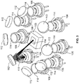
FIG. 3 depicts a perspective view of an arrangement of laser diodes around a reflective phosphor plate, showing how laser light emitted from a single laser diode is reflected onto the reflective phosphor plate -
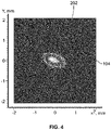
FIG. 4 illustrates the elliptical pattern that the reflected laser light depicted inFIG. 3 forms at a predetermined position on thereflective phosphor plate 104; -
FIG. 5 depicts a perspective view of an arrangement of laser diodes around a reflective phosphor plate, showing how laser light emitted from all of the laser diodes is reflected onto the reflective phosphor plate -
FIG. 6 illustrates the circular pattern that the collective reflected laser light depicted inFIG. 5 forms at the predetermined position on thereflective phosphor plate 104; -
FIG. 7 depicts the irradiance versus position profile of the reflected light for the arrangement depicted inFIG. 5 ; and -
FIG. 8 depicts a cross section view of another embodiment of a compact laser light assembly. - The following detailed description is merely exemplary in nature and is not intended to limit the invention or the application and uses of the invention. As used herein, the word "exemplary" means "serving as an example, instance, or illustration." Thus, any embodiment described herein as "exemplary" is not necessarily to be construed as preferred or advantageous over other embodiments. All of the embodiments described herein are exemplary embodiments provided to enable persons skilled in the art to make or use the invention and not to limit the scope of the invention which is defined by the claims. Furthermore, there is no intention to be bound by any expressed or implied theory presented in the preceding technical field, background, brief summary, or the following detailed description.
- Referring now to
FIG. 1 , a cross section view of one embodiment of a compact laserlight assembly 100 is depicted and includes asubstrate 102, areflective phosphor plate 104, a plurality oflaser diodes 106, alight shield 108, at least onemirror 112, a plurality of beam-shapinglenses 114, and afirst lens 116. Thesubstrate 102 has a plurality ofopenings 118 formed therein, and functions as a heat sink. The substrate is thus preferably constructed of a suitable material. Some non-limiting examples of suitable materials include aluminum, various aluminum alloys, copper, steel, and thermally conductive plastics or composites. - The
reflective phosphor plate 104 is coupled to thesubstrate 102 and is configured to convert incident blue laser light into white light. In the depicted embodiment, thereflective phosphor plate 104 is coupled to thesubstrate 102 via amount plate 122. Themount plate 122, which may comprise copper, aluminum or any one of numerous thermally conductive materials, is disposed in, and is coupled to, thesubstrate 102, and has thereflective phosphor plate 104 mounted thereon. - The
laser diodes 106 are mounted on thesubstrate 102 and, as depicted more clearly in simplified form inFIG. 2 , are evenly spaced about a radius (R) that is measured from apredetermined position 202 on thereflective phosphor plate 104. More specifically, at least in the embodiment depicted inFIG. 1 , eachlaser diode 106 is disposed, one each, within a different one of theopenings 118 formed in thesubstrate 102. Thelaser diodes 106 are each configured, upon being energized, to emit blue laser light. It will be appreciated that the number oflaser diodes 106 included in the laserlight assembly 100 may vary. In the depicted embodiments, the number of laser diodes is an even number, but the number could also be an odd number. Although the specific number is not depicted inFIG. 1 , in the embodiment depicted inFIG. 2 , the number oflaser diodes 106 is six, and in the embodiment depicted inFIGS. 3 and5 , the number oflaser diodes 106 is eight. In other embodiments, the laserlight assembly 100 may include more or less than this number of laser diodes. - The
light shield 108 is coupled to thesubstrate 102 and is configured to prevent the blue laser light emitted by thelaser diodes 106 from escaping theassembly 100. To implement this functionality, thelight shield 108 is suitably shaped, and is formed of a suitable material that is opaque to, and will reflect or absorb, the blue laser light emitted by thelaser diodes 106. This prevents stray laser light from escaping the device where it could cause a safety hazard or unwanted blue spots in the final output beam. Some non-limiting examples of suitable materials include steel, aluminum, and various opaque plastic materials. In a particular preferred embodiment, thelight shield 108 is formed of aluminum. - The at least one
mirror 112 is disposed between the light shield and the plurality oflaser diodes 106. In the depicted embodiment, the at least onemirror 112 is mounted on thelight shield 108 and is spaced apart from the plurality oflaser diodes 106 and thereflective phosphor plate 104. The at least onemirror 112 is disposed to reflect the blue laser light emitted from eachlaser diode 106 toward thepredetermined position 202 on thereflective phosphor plate 104. As a result, and as noted above, thereflective phosphor plate 104 will convert the incident blue laser light into white light. It will be appreciated that the at least onemirror 112 may be implemented using a plurality of mirrors. In one particular embodiment, as depicted more clearly inFIGS. 3 ,5 , and8 , there is onemirror 112 associated with and spaced apart from each of thelaser diodes 106. Each of themirrors 112 in this embodiment is disposed to reflect the laser light emitted from its associatedlaser diode 106 toward thepredetermined position 202 on thereflective phosphor plate 104. - Referring again to
FIG. 1 , the beam-shapinglenses 114 are mounted on thesubstrate 102, and each beam-shapinglens 114 is disposed between a different one of thelaser diodes 106 and the at least onemirror 112. In the depicted embodiment, each beam-shapinglens 114 is disposed within a different one of theopenings 118 formed in thesubstrate 102, though theselenses 114 could be disposed external to theopenings 118 in other embodiments. Although the beam-shapinglenses 114 may be variously implemented, in a particular preferred embodiment, each is implemented using a focusing lens, which creates the smallest possible spot on thereflective phosphor plate 104. - The
first lens 116 is mounted on thelight shield 108 and is spaced apart from thereflective phosphor plate 104. Thefirst lens 116 is disposed to receive and collimate the white light emitted from the reflective phosphor plate. Although thefirst lens 116 may be variously implemented, in a particular preferred embodiment, it is implemented using a collimating lens. - Before proceeding further, it is noted that the depicted laser
light assembly 100 may additionally include amount flange 124. Themount flange 124, when included, is coupled to thesubstrate 102 and is configured to mount the laserlight assembly 100 on a surface (non-illustrated). The surface may vary and may depend on the specific end-use for the laserlight assembly 100. - With reference now to
FIGS. 3 and4 , it is seen that when the blue laser light emitted by each of the plurality oflaser diodes 106 is reflected by its associatedmirror 112, it is reflected in an elliptical pattern at thepredetermined position 202 on thereflective phosphor plate 104. To more clearly illustrate this,FIGS. 3 and4 depict the resultant pattern when only one of thelaser diodes 106 emits blue laser light. However, asFIGS. 5 and6 depict, when all of thelaser diodes 106 are emitting blue laser light, each of the individual elliptical patterns collectively forms a relatively small, substantially circular pattern at thepredetermined position 202 on thereflective phosphor plate 104. This ensures, as depicted inFIG. 7 , that the white light emitted from thereflective phosphor plate 104 is emitted as a fairly narrow beam. This, in turn, contributes to the compactness of theassembly 100. - Referring now to
FIG. 8 , it is seen that in some embodiments the laser light assembly may additionally include alens housing 802 and asecond lens 804. When included, thelens housing 802 is coupled to thelight shield 108. Thesecond lens 804 is mounted at least partially in thelens housing 802, is spaced apart from thefirst lens 116, and is disposed to receive and collimate the white light that passes through thefirst lens 116. Although thesecond lens 804 may be variously implemented, in a particular preferred embodiment, it is implemented using a collimating lens. - For completeness,
FIG. 8 also depicts theblue laser light 806 that is emitted by each of thelaser diodes 106, and that passes through the beam-shapinglenses 114 and is reflected by the at least onemirror 112 toward thepredetermined position 202 on thereflective phosphor plate 104.FIG. 8 also depicts thewhite light 808 that is emitted by thereflective phosphor plate 104, and that is received and collimated by the first andsecond lenses - The laser light assembly described herein provides a relatively high-output light source, while being smaller, lighter in weight, and simpler in configuration as compared to existing light sources.
- In this document, relational terms such as first and second, and the like may be used solely to distinguish one entity or action from another entity or action without necessarily requiring or implying any actual such relationship or order between such entities or actions. Numerical ordinals such as "first," "second," "third," etc. simply denote different singles of a plurality and do not imply any order or sequence unless specifically defined by the claim language. The sequence of the text in any of the claims does not imply that process steps must be performed in a temporal or logical order according to such sequence unless it is specifically defined by the language of the claim. The process steps may be interchanged in any order without departing from the scope of the invention as long as such an interchange does not contradict the claim language and is not logically nonsensical.
- Furthermore, depending on the context, words such as "connect" or "coupled to" used in describing a relationship between different elements do not imply that a direct physical connection must be made between these elements. For example, two elements may be connected to each other physically, electronically, logically, or in any other manner, through one or more additional elements.
- While at least one exemplary embodiment has been presented in the foregoing detailed description of the invention, it should be appreciated that a vast number of variations exist. It should also be appreciated that the exemplary embodiment or exemplary embodiments are only examples, and are not intended to limit the scope, applicability, or configuration of the invention in any way. Rather, the foregoing detailed description will provide those skilled in the art with a convenient road map for implementing an exemplary embodiment of the invention. It being understood that various changes may be made in the function and arrangement of elements described in an exemplary embodiment without departing from the scope of the invention as set forth in the appended claims.
Claims (12)
- A laser light assembly, comprising:a substrate;a reflective phosphor plate coupled to the substrate, the reflective phosphor plate configured to convert incident blue laser light into white light;a plurality of laser diodes mounted on the substrate and evenly spaced about a radius that is measured from a predetermined position on the reflective phosphor plate, each laser diode configured to emit blue laser light;a light shield coupled to the substrate and configured to prevent the blue laser light emitted by the plurality of laser diodes from escaping the assembly;at least one mirror disposed between the light shield and the plurality of laser diodes, the at least one mirror spaced apart from the plurality of laser diodes and the reflective phosphor plate and disposed to reflect the blue laser light emitted from each laser diode toward the predetermined position on the reflective phosphor plate, whereby the reflective phosphor plate emits white light;a plurality of beam-shaping lenses mounted on the substrate, each beam-shaping lens disposed between a different one of the laser diodes and the at least one mirror; anda first lens mounted on the light shield, the first lens spaced apart from the reflective phosphor plate and disposed to receive the white emitted from the reflective phosphor plate.
- The laser light assembly of claim 1, wherein each beam-shaping lens is a focusing lens.
- The laser light assembly of claim 1, wherein:the substrate has a plurality of openings formed therein; andeach of the plurality of laser diodes is disposed within a different one of the openings.
- The laser light assembly of claim 3, wherein each beam-shaping lens is disposed within a different one of the plurality of openings.
- The laser light assembly of claim 1, wherein the light shield comprises a material selected from the group consisting of steel, aluminum, and opaque plastic.
- The laser light assembly of claim 1, further comprising:
a second lens spaced apart from the first lens and disposed to receive and collimate the white light that passes through the first lens. - The laser light assembly of claim 1, wherein the first lens and the second lens are each collimating lenses.
- The laser light assembly of claim 1, further comprising:
a lens housing coupled to the shield, the lens housing having the second lens mounted at least partially therein. - The laser light assembly of claim 1, further comprising:
a mount plate disposed in and coupled to the substrate, the mount plate having the reflective phosphor plate mounted thereon. - The laser light assembly of claim 1, wherein:the at least one mirror comprises a plurality of mirrors;each mirror is associated with and is spaced apart from a different one of the plurality of laser diodes; andeach mirror is disposed to reflect the laser light emitted from its associated laser diode toward the predetermined position on the reflective phosphor plate.
- The laser light assembly of claim 1, further comprising:
a mount flange coupled to the substrate and configured to mount the laser light assembly on a surface. - The laser light assembly of claim 1, wherein:the blue laser light emitted by each of the plurality of laser diodes is reflected by the at least one mirror in an individual elliptical pattern toward the predetermined position on the reflective phosphor plate; andeach of the individual elliptical patterns collectively forms a substantially circular pattern at the predetermined position on the reflective phosphor plate.
Applications Claiming Priority (2)
| Application Number | Priority Date | Filing Date | Title |
|---|---|---|---|
| IN202011053133 | 2020-12-07 | ||
| US17/156,899 US11175007B1 (en) | 2020-12-07 | 2021-01-25 | Compact laser light assembly |
Publications (1)
| Publication Number | Publication Date |
|---|---|
| EP4009455A1 true EP4009455A1 (en) | 2022-06-08 |
Family
ID=78524223
Family Applications (1)
| Application Number | Title | Priority Date | Filing Date |
|---|---|---|---|
| EP21210614.0A Pending EP4009455A1 (en) | 2020-12-07 | 2021-11-25 | Compact laser light assembly |
Country Status (2)
| Country | Link |
|---|---|
| US (1) | US11175007B1 (en) |
| EP (1) | EP4009455A1 (en) |
Families Citing this family (1)
| Publication number | Priority date | Publication date | Assignee | Title |
|---|---|---|---|---|
| TWI855941B (en) * | 2023-12-14 | 2024-09-11 | 台灣彩光科技股份有限公司 | Smart projection headlight |
Citations (8)
| Publication number | Priority date | Publication date | Assignee | Title |
|---|---|---|---|---|
| US20130314937A1 (en) * | 2012-05-24 | 2013-11-28 | Sharp Kabushiki Kaisha | Light projecting device and vehicular headlamp |
| US20150062943A1 (en) * | 2013-08-28 | 2015-03-05 | Sharp Kabushiki Kaisha | Light-emitting unit, light-emitting device, illumination device, and vehicle headlight |
| US20170153003A1 (en) * | 2015-11-27 | 2017-06-01 | Valeo Vision | Light-emitting device for an automotive vehicle headlamp lighting module and associated lighting module and headlamps |
| US20180292059A1 (en) * | 2015-11-06 | 2018-10-11 | Sharp Kabushiki Kaisha | Light-emitting device |
| US20190097095A1 (en) * | 2016-05-13 | 2019-03-28 | Panasonic Intellectual Property Management Co., Ltd. | Light source device and lighting device |
| CN110107826A (en) * | 2019-06-13 | 2019-08-09 | 广州光联电子科技有限公司 | A kind of laser flashlight optical system folding more optical axises and laser flashlight |
| WO2020019085A1 (en) * | 2018-07-27 | 2020-01-30 | Optomak, Inc. | Compact high-spectral-radiance light source including a parabolic mirror and plano-convex fluorescent body |
| CN111552144A (en) * | 2020-06-29 | 2020-08-18 | 北京镭创高科光电科技有限公司 | Laser light source and lighting apparatus |
Family Cites Families (15)
| Publication number | Priority date | Publication date | Assignee | Title |
|---|---|---|---|---|
| US20110216550A1 (en) | 2010-03-02 | 2011-09-08 | Teruo Koike | Vehicle light |
| US9816677B2 (en) | 2010-10-29 | 2017-11-14 | Sharp Kabushiki Kaisha | Light emitting device, vehicle headlamp, illumination device, and laser element |
| TW201405048A (en) | 2012-07-19 | 2014-02-01 | 瓦維安股份有限公司 | Phosphor-based luminaire for projection displays |
| US9869442B2 (en) | 2014-06-26 | 2018-01-16 | Texas Instruments Incorporated | Hybrid illumination system having a blue laser diode, dichroic mirror and yellow transmissive phosphor converter for generating white light |
| WO2016064733A2 (en) | 2014-10-20 | 2016-04-28 | Ipg Photonics Corporation | Vehicular lighting system |
| US11340520B2 (en) | 2015-07-02 | 2022-05-24 | Texas Instruments Incorporated | Apparatus for high efficiency laser static phosphor module |
| US10879673B2 (en) | 2015-08-19 | 2020-12-29 | Soraa Laser Diode, Inc. | Integrated white light source using a laser diode and a phosphor in a surface mount device package |
| JPWO2017056469A1 (en) * | 2015-09-29 | 2018-07-12 | パナソニックIpマネジメント株式会社 | Light source device and light projecting device |
| JP6800224B2 (en) | 2015-11-05 | 2020-12-16 | ルミレッズ ホールディング ベーフェー | Laser-based light source with emission control |
| WO2017104167A1 (en) * | 2015-12-17 | 2017-06-22 | シャープ株式会社 | Illumination device and vehicular headlight |
| US10587090B1 (en) | 2015-12-31 | 2020-03-10 | Soraa Laser Diode, Inc. | Safe laser light |
| JP6785454B2 (en) * | 2016-02-09 | 2020-11-18 | パナソニックIpマネジメント株式会社 | Light source device and floodlight device |
| US11002414B2 (en) * | 2018-08-09 | 2021-05-11 | Sharp Kabushiki Kaisha | Light source device |
| US11421843B2 (en) | 2018-12-21 | 2022-08-23 | Kyocera Sld Laser, Inc. | Fiber-delivered laser-induced dynamic light system |
| JP7372522B2 (en) * | 2019-08-22 | 2023-11-01 | 日亜化学工業株式会社 | light emitting device |
-
2021
- 2021-01-25 US US17/156,899 patent/US11175007B1/en active Active
- 2021-11-25 EP EP21210614.0A patent/EP4009455A1/en active Pending
Patent Citations (8)
| Publication number | Priority date | Publication date | Assignee | Title |
|---|---|---|---|---|
| US20130314937A1 (en) * | 2012-05-24 | 2013-11-28 | Sharp Kabushiki Kaisha | Light projecting device and vehicular headlamp |
| US20150062943A1 (en) * | 2013-08-28 | 2015-03-05 | Sharp Kabushiki Kaisha | Light-emitting unit, light-emitting device, illumination device, and vehicle headlight |
| US20180292059A1 (en) * | 2015-11-06 | 2018-10-11 | Sharp Kabushiki Kaisha | Light-emitting device |
| US20170153003A1 (en) * | 2015-11-27 | 2017-06-01 | Valeo Vision | Light-emitting device for an automotive vehicle headlamp lighting module and associated lighting module and headlamps |
| US20190097095A1 (en) * | 2016-05-13 | 2019-03-28 | Panasonic Intellectual Property Management Co., Ltd. | Light source device and lighting device |
| WO2020019085A1 (en) * | 2018-07-27 | 2020-01-30 | Optomak, Inc. | Compact high-spectral-radiance light source including a parabolic mirror and plano-convex fluorescent body |
| CN110107826A (en) * | 2019-06-13 | 2019-08-09 | 广州光联电子科技有限公司 | A kind of laser flashlight optical system folding more optical axises and laser flashlight |
| CN111552144A (en) * | 2020-06-29 | 2020-08-18 | 北京镭创高科光电科技有限公司 | Laser light source and lighting apparatus |
Also Published As
| Publication number | Publication date |
|---|---|
| US11175007B1 (en) | 2021-11-16 |
Similar Documents
| Publication | Publication Date | Title |
|---|---|---|
| KR101847932B1 (en) | Lighting device module | |
| US10203079B2 (en) | Lighting apparatus with conversion device | |
| US10228106B2 (en) | Luminaire with light source and spaced-apart luminescent body | |
| US9903550B2 (en) | Lighting device with light mixing element and luminescent volume | |
| JP5939418B2 (en) | Vehicle lamp unit | |
| US20150124432A1 (en) | Light emitting device, illumination device, and vehicle headlamp | |
| US20170343179A1 (en) | Lighting apparatus | |
| US10851960B2 (en) | Vehicular lighting fixture | |
| US11175007B1 (en) | Compact laser light assembly | |
| US9920902B2 (en) | Laser source for exiting a phosphor and light source comprising a phosphor | |
| JP2019212367A (en) | Lamp unit | |
| KR20210034633A (en) | Automotive headlamps including ellipsoid reflectors and collimators | |
| JP2014003018A (en) | Led runway illumination assembly and dedicated optical device | |
| CN107345641B (en) | Lighting module comprising a laser element | |
| JP6858015B2 (en) | Illuminator | |
| JP6736349B2 (en) | Vehicle lighting system | |
| KR101754168B1 (en) | Lighting device module | |
| KR101716129B1 (en) | Lighting device module | |
| WO2009157098A1 (en) | Light beam adder | |
| CN211694705U (en) | Vehicle-mounted laser lamp | |
| CN107940268B (en) | Laser module and laser lighting | |
| KR101756413B1 (en) | Lighting device module | |
| KR101754167B1 (en) | Lighting device module | |
| CN107166288B (en) | Lighting device for vehicle | |
| JP2020149808A (en) | lighting equipment |
Legal Events
| Date | Code | Title | Description |
|---|---|---|---|
| PUAI | Public reference made under article 153(3) epc to a published international application that has entered the european phase |
Free format text: ORIGINAL CODE: 0009012 |
|
| STAA | Information on the status of an ep patent application or granted ep patent |
Free format text: STATUS: THE APPLICATION HAS BEEN PUBLISHED |
|
| AK | Designated contracting states |
Kind code of ref document: A1 Designated state(s): AL AT BE BG CH CY CZ DE DK EE ES FI FR GB GR HR HU IE IS IT LI LT LU LV MC MK MT NL NO PL PT RO RS SE SI SK SM TR |
|
| STAA | Information on the status of an ep patent application or granted ep patent |
Free format text: STATUS: REQUEST FOR EXAMINATION WAS MADE |
|
| 17P | Request for examination filed |
Effective date: 20221207 |
|
| RBV | Designated contracting states (corrected) |
Designated state(s): AL AT BE BG CH CY CZ DE DK EE ES FI FR GB GR HR HU IE IS IT LI LT LU LV MC MK MT NL NO PL PT RO RS SE SI SK SM TR |
|
| STAA | Information on the status of an ep patent application or granted ep patent |
Free format text: STATUS: EXAMINATION IS IN PROGRESS |
|
| RIC1 | Information provided on ipc code assigned before grant |
Ipc: F21S 41/176 20180101ALN20230228BHEP Ipc: F21S 41/16 20180101ALN20230228BHEP Ipc: F21V 9/35 20180101ALN20230228BHEP Ipc: H01S 5/024 20060101ALN20230228BHEP Ipc: H01S 5/02 20060101ALN20230228BHEP Ipc: F21Y 115/30 20160101ALN20230228BHEP Ipc: H01S 5/40 20060101ALN20230228BHEP Ipc: H01S 5/02212 20210101ALN20230228BHEP Ipc: F21V 7/26 20180101ALI20230228BHEP Ipc: F21V 7/00 20060101ALI20230228BHEP Ipc: B64D 47/02 20060101ALI20230228BHEP Ipc: H01S 5/323 20060101ALI20230228BHEP Ipc: H01S 5/00 20060101AFI20230228BHEP |
|
| 17Q | First examination report despatched |
Effective date: 20230313 |
|
| P01 | Opt-out of the competence of the unified patent court (upc) registered |
Effective date: 20230421 |