EP4009394A1 - Anti-dendrite negative electrodes, and the electrochemical cells containing them - Google Patents
Anti-dendrite negative electrodes, and the electrochemical cells containing them Download PDFInfo
- Publication number
- EP4009394A1 EP4009394A1 EP20306510.7A EP20306510A EP4009394A1 EP 4009394 A1 EP4009394 A1 EP 4009394A1 EP 20306510 A EP20306510 A EP 20306510A EP 4009394 A1 EP4009394 A1 EP 4009394A1
- Authority
- EP
- European Patent Office
- Prior art keywords
- layer
- negative electrode
- current collector
- alloys
- lithium
- Prior art date
- Legal status (The legal status is an assumption and is not a legal conclusion. Google has not performed a legal analysis and makes no representation as to the accuracy of the status listed.)
- Granted
Links
Images



Classifications
-
- H—ELECTRICITY
- H01—ELECTRIC ELEMENTS
- H01M—PROCESSES OR MEANS, e.g. BATTERIES, FOR THE DIRECT CONVERSION OF CHEMICAL ENERGY INTO ELECTRICAL ENERGY
- H01M4/00—Electrodes
- H01M4/02—Electrodes composed of, or comprising, active material
- H01M4/13—Electrodes for accumulators with non-aqueous electrolyte, e.g. for lithium-accumulators; Processes of manufacture thereof
- H01M4/134—Electrodes based on metals, Si or alloys
-
- H—ELECTRICITY
- H01—ELECTRIC ELEMENTS
- H01M—PROCESSES OR MEANS, e.g. BATTERIES, FOR THE DIRECT CONVERSION OF CHEMICAL ENERGY INTO ELECTRICAL ENERGY
- H01M4/00—Electrodes
- H01M4/02—Electrodes composed of, or comprising, active material
- H01M4/13—Electrodes for accumulators with non-aqueous electrolyte, e.g. for lithium-accumulators; Processes of manufacture thereof
-
- H—ELECTRICITY
- H01—ELECTRIC ELEMENTS
- H01M—PROCESSES OR MEANS, e.g. BATTERIES, FOR THE DIRECT CONVERSION OF CHEMICAL ENERGY INTO ELECTRICAL ENERGY
- H01M4/00—Electrodes
- H01M4/02—Electrodes composed of, or comprising, active material
- H01M4/36—Selection of substances as active materials, active masses, active liquids
- H01M4/362—Composites
- H01M4/366—Composites as layered products
-
- H—ELECTRICITY
- H01—ELECTRIC ELEMENTS
- H01M—PROCESSES OR MEANS, e.g. BATTERIES, FOR THE DIRECT CONVERSION OF CHEMICAL ENERGY INTO ELECTRICAL ENERGY
- H01M10/00—Secondary cells; Manufacture thereof
- H01M10/05—Accumulators with non-aqueous electrolyte
- H01M10/052—Li-accumulators
-
- H—ELECTRICITY
- H01—ELECTRIC ELEMENTS
- H01M—PROCESSES OR MEANS, e.g. BATTERIES, FOR THE DIRECT CONVERSION OF CHEMICAL ENERGY INTO ELECTRICAL ENERGY
- H01M10/00—Secondary cells; Manufacture thereof
- H01M10/05—Accumulators with non-aqueous electrolyte
- H01M10/052—Li-accumulators
- H01M10/0525—Rocking-chair batteries, i.e. batteries with lithium insertion or intercalation in both electrodes; Lithium-ion batteries
-
- H—ELECTRICITY
- H01—ELECTRIC ELEMENTS
- H01M—PROCESSES OR MEANS, e.g. BATTERIES, FOR THE DIRECT CONVERSION OF CHEMICAL ENERGY INTO ELECTRICAL ENERGY
- H01M10/00—Secondary cells; Manufacture thereof
- H01M10/05—Accumulators with non-aqueous electrolyte
- H01M10/056—Accumulators with non-aqueous electrolyte characterised by the materials used as electrolytes, e.g. mixed inorganic/organic electrolytes
- H01M10/0561—Accumulators with non-aqueous electrolyte characterised by the materials used as electrolytes, e.g. mixed inorganic/organic electrolytes the electrolyte being constituted of inorganic materials only
- H01M10/0562—Solid materials
-
- H—ELECTRICITY
- H01—ELECTRIC ELEMENTS
- H01M—PROCESSES OR MEANS, e.g. BATTERIES, FOR THE DIRECT CONVERSION OF CHEMICAL ENERGY INTO ELECTRICAL ENERGY
- H01M4/00—Electrodes
- H01M4/02—Electrodes composed of, or comprising, active material
- H01M4/04—Processes of manufacture in general
- H01M4/0402—Methods of deposition of the material
- H01M4/0404—Methods of deposition of the material by coating on electrode collectors
-
- H—ELECTRICITY
- H01—ELECTRIC ELEMENTS
- H01M—PROCESSES OR MEANS, e.g. BATTERIES, FOR THE DIRECT CONVERSION OF CHEMICAL ENERGY INTO ELECTRICAL ENERGY
- H01M4/00—Electrodes
- H01M4/02—Electrodes composed of, or comprising, active material
- H01M4/04—Processes of manufacture in general
- H01M4/0402—Methods of deposition of the material
- H01M4/0407—Methods of deposition of the material by coating on an electrolyte layer
-
- H—ELECTRICITY
- H01—ELECTRIC ELEMENTS
- H01M—PROCESSES OR MEANS, e.g. BATTERIES, FOR THE DIRECT CONVERSION OF CHEMICAL ENERGY INTO ELECTRICAL ENERGY
- H01M4/00—Electrodes
- H01M4/02—Electrodes composed of, or comprising, active material
- H01M4/04—Processes of manufacture in general
- H01M4/0438—Processes of manufacture in general by electrochemical processing
- H01M4/044—Activating, forming or electrochemical attack of the supporting material
- H01M4/0445—Forming after manufacture of the electrode, e.g. first charge, cycling
-
- H—ELECTRICITY
- H01—ELECTRIC ELEMENTS
- H01M—PROCESSES OR MEANS, e.g. BATTERIES, FOR THE DIRECT CONVERSION OF CHEMICAL ENERGY INTO ELECTRICAL ENERGY
- H01M4/00—Electrodes
- H01M4/02—Electrodes composed of, or comprising, active material
- H01M4/13—Electrodes for accumulators with non-aqueous electrolyte, e.g. for lithium-accumulators; Processes of manufacture thereof
- H01M4/139—Processes of manufacture
-
- H—ELECTRICITY
- H01—ELECTRIC ELEMENTS
- H01M—PROCESSES OR MEANS, e.g. BATTERIES, FOR THE DIRECT CONVERSION OF CHEMICAL ENERGY INTO ELECTRICAL ENERGY
- H01M4/00—Electrodes
- H01M4/02—Electrodes composed of, or comprising, active material
- H01M4/36—Selection of substances as active materials, active masses, active liquids
- H01M4/38—Selection of substances as active materials, active masses, active liquids of elements or alloys
-
- H—ELECTRICITY
- H01—ELECTRIC ELEMENTS
- H01M—PROCESSES OR MEANS, e.g. BATTERIES, FOR THE DIRECT CONVERSION OF CHEMICAL ENERGY INTO ELECTRICAL ENERGY
- H01M4/00—Electrodes
- H01M4/02—Electrodes composed of, or comprising, active material
- H01M4/64—Carriers or collectors
- H01M4/66—Selection of materials
-
- H—ELECTRICITY
- H01—ELECTRIC ELEMENTS
- H01M—PROCESSES OR MEANS, e.g. BATTERIES, FOR THE DIRECT CONVERSION OF CHEMICAL ENERGY INTO ELECTRICAL ENERGY
- H01M4/00—Electrodes
- H01M4/02—Electrodes composed of, or comprising, active material
- H01M4/64—Carriers or collectors
- H01M4/66—Selection of materials
- H01M4/661—Metal or alloys, e.g. alloy coatings
-
- H—ELECTRICITY
- H01—ELECTRIC ELEMENTS
- H01M—PROCESSES OR MEANS, e.g. BATTERIES, FOR THE DIRECT CONVERSION OF CHEMICAL ENERGY INTO ELECTRICAL ENERGY
- H01M4/00—Electrodes
- H01M4/02—Electrodes composed of, or comprising, active material
- H01M4/64—Carriers or collectors
- H01M4/66—Selection of materials
- H01M4/661—Metal or alloys, e.g. alloy coatings
- H01M4/662—Alloys
-
- H—ELECTRICITY
- H01—ELECTRIC ELEMENTS
- H01M—PROCESSES OR MEANS, e.g. BATTERIES, FOR THE DIRECT CONVERSION OF CHEMICAL ENERGY INTO ELECTRICAL ENERGY
- H01M4/00—Electrodes
- H01M4/02—Electrodes composed of, or comprising, active material
- H01M2004/021—Physical characteristics, e.g. porosity, surface area
-
- H—ELECTRICITY
- H01—ELECTRIC ELEMENTS
- H01M—PROCESSES OR MEANS, e.g. BATTERIES, FOR THE DIRECT CONVERSION OF CHEMICAL ENERGY INTO ELECTRICAL ENERGY
- H01M4/00—Electrodes
- H01M4/02—Electrodes composed of, or comprising, active material
- H01M2004/026—Electrodes composed of, or comprising, active material characterised by the polarity
- H01M2004/027—Negative electrodes
-
- H—ELECTRICITY
- H01—ELECTRIC ELEMENTS
- H01M—PROCESSES OR MEANS, e.g. BATTERIES, FOR THE DIRECT CONVERSION OF CHEMICAL ENERGY INTO ELECTRICAL ENERGY
- H01M2300/00—Electrolytes
- H01M2300/0017—Non-aqueous electrolytes
- H01M2300/0065—Solid electrolytes
- H01M2300/0068—Solid electrolytes inorganic
-
- Y—GENERAL TAGGING OF NEW TECHNOLOGICAL DEVELOPMENTS; GENERAL TAGGING OF CROSS-SECTIONAL TECHNOLOGIES SPANNING OVER SEVERAL SECTIONS OF THE IPC; TECHNICAL SUBJECTS COVERED BY FORMER USPC CROSS-REFERENCE ART COLLECTIONS [XRACs] AND DIGESTS
- Y02—TECHNOLOGIES OR APPLICATIONS FOR MITIGATION OR ADAPTATION AGAINST CLIMATE CHANGE
- Y02E—REDUCTION OF GREENHOUSE GAS [GHG] EMISSIONS, RELATED TO ENERGY GENERATION, TRANSMISSION OR DISTRIBUTION
- Y02E60/00—Enabling technologies; Technologies with a potential or indirect contribution to GHG emissions mitigation
- Y02E60/10—Energy storage using batteries
Definitions
- the present invention concerns the field of energy storage, and particularly the field of batteries, such as lithium batteries.
- Lithium-ion batteries are now widely used as they offer outstanding energy and volume densities; they are the first choice solution for portable electronic devices or electric and hybrid vehicles, energy storage systems (ESS).
- ESS energy storage systems
- Lithium-ion batteries involve the reversible exchange of the Lithium ions between the positive electrode and the negative electrode that are separated by a separator, and both electrodes intercalate/deintercalate Lithium Ions.
- the negative electrode comprises elemental lithium which deposits on the negative electrode during the charge, and dissolves during the discharge.
- Solid-state batteries have been recently developed and offer promising prospects perspective for Li-ion batteries. It requires new materials and approaches. In particular, their assembling requires the application of high pressure (> 500MPa) and temperature (60-100°C) for densification and removing all voids and decreasing interface resistances.
- high pressure > 500MPa
- temperature 60-100°C
- the use of negative electrodes containing metallic lithium during assembly is generally not possible due to the lithium metal softness, plastic deformation and change of the shape of Lithium. This makes it difficult to obtain the required level density and consequently, reduces the electrochemical performance.
- US 2020/0176810 discloses an anode-free solid-state battery comprising an anti-dendrite functional layer along the solid electrolyte layer, and a scaffold layer along the anti-dendrite functional layer and the current collector.
- the functional layer can comprise metals
- the scaffold layer is composed of an organic material, metal oxide or metal-inorganic framework.
- An optional second anti-dendrite layer can be intercalated between the current collector and the scaffold layer.
- the scaffold layer intercalated between the two anti-dendrite layers.
- the scaffold layer has a relatively low lithium transportation ability and decreases the synergy between the 2 anti-dendrite layers leading to lower cycle life and lower chargeability.
- electrochemical cells should inhibit the reductive decomposition of the solid-state electrolyte, allow high-pressure assembling, and provide high energy density.
- the present invention therefore provides a negative electrode of an electrochemical cell comprising:
- negative electrode designates when the accumulator is discharging, the electrode functioning as an anode and when the accumulator is charging, the electrode functioning as a cathode, the anode being defined as the electrode where an electrochemical oxidation reaction (emission of electrons) occurs, while the cathode is the seat of reduction.
- the term negative electrode refers to the electrode from which electrons leave, and from which cations (Li+) are released in discharge.
- the present negative electrode may be designated as a combination of Li-ion electrode and Li metal electrode. Initially during the first charge Li + ions create Li metal alloy and thereafter, elemental Lithium metal is electroplated, as in the Li-metal battery.
- the negative electrode initially does not comprise metal Lithium, but includes lithium after the first charge:
- the layers are thus altered during the first cycling in that they are lithiated : their constituting metal or metalloid forms an alloy with lithium.
- Said alloys are typically rich in lithium in that they comprise maximum amount lithium, for example Li 4.4 Sn (990 mAh/g of Sn and 2100 mAh/cm 3 ) or Li 3 Mg (3350 mAh/g of Mg and 1770 mAh/cm 3 ) and have maximal coefficient of lithium ions diffusion (diffusion in Li-Zn alloy electrodes prepared by different methods may vary from 10 -7 to 10 -9 cm 2 S -1 ).
- the layers further include lithium alloys.
- the negative electrode of the invention may also further comprise a layer of metal lithium plated between the current collector and the layer (1).
- lithium metal alloys layers are electron and lithium conductive, dense and robust enough to suppress dendrite formation.
- the initial composition of each of the n layers is such that it can create an alloy with the highest coefficient of diffusion of Li + ions, typically between 10 -6 (LiAg alloy) and 10 -8 cm 2 s -1 by application or adaptation of the method described by Suzuki et al Electrochemistry 74(4), 303-308, 2006 .
- each of the n layers or the material constituting the same has a determined potential of lithiation.
- the layers are arranged in specific sequence based on the value of their respective potential of lithiation.
- the potential of lithiation is defined as the affinity to form alloys with lithium. It is expressed in Volt and can be measured electrochemically by measuring the potential at which the reduction occurs. It is illustrated by the lithiophilicity of the material constituting each layer, (ie) its affinity for lithium and thus its ability to form alloys with lithium.
- the layers are arranged so that there is a positive gradient of potential of lithiation from the current collector.
- layer (i+1) has a higher potential of lithiation than that of layer (i) which is immediately beneath it, meaning that the materials with lower potentials of lithiation are located closer to the current collector, whereas materials with higher potentials of lithiation are located further from the current collector.
- the metals and/or alloys and/or metalloids and/or metalloids alloys can be chosen from the group comprising Mg, Al, Zn, Cd, Ti, Cr, Mn, Co, Fe, Ag, Au, In, Sn, Pb, Bi, Sb, Si, B, and the alloys thereof.
- the metals having the higher potentials of lithiation include bismuth (0.85 V vs Li), indium (0.62V), Antimony (0.95 V) and similar.
- the layer (n) (ie) furthest from the current collector comprises one or more metals chosen from bismuth, indium, Antimony or their alloys thereof.
- the metals having the lower potentials of lithiation include zinc (0.157 V), magnesium (0.03 V) and similar.
- the layer (1) closest to the current collector comprises zinc, magnesium and/or the alloys thereof.
- the plurality of metal layers arranged according to the above gradient of potential of lithiation together with their nature (high diffusion coefficients of Li + ions) allow the effective diffusion of Li + ions during charge through the layers towards the current collector, so as to uniformly deposit a layer of metal Lithium, deposited between the layers and the current collector.
- the layers structure and/or their arrangement may have several roles and implications: Mainly, they reduce the nucleation energy of lithium. They conduct lithium, in that they allow Li + ions to transit from the electrolyte layer. In addition, they can also allow homogenization of the lithium deposit by allowing the formation of local batteries: in fact, during charging, a potential difference is created in the thickness of the electrode; this difference in potentials can then allow an electrochemical rebalancing on the thickness of the electrode by oxidation of metallic lithium in the most positive potential zones and a reduction of Li + in the most negative potential zones.
- the negative electrode structure according to the invention thus allows the elemental (ie) metal lithium to be deposited homogeneously on the current collector while greatly limiting the volume variations of the negative electrode.
- lithium provides maximal gravimetric and volumetric capacities, as the layers have small thickness, typically comprised between 0.05 and 20 ⁇ m, preferably between 0.2 and 10 ⁇ m, and a low weight, with a loading generally comprised between 0.1 and 10 mg/cm 2 .
- active positive electrode materials exhibit an irreversible capacity loss of 5-30% during the first cycle.
- this lithium is stored in the negative electrode and partially consumed for creation of the solid electrolyte interface (SEI) layer.
- SEI solid electrolyte interface
- this excess of lithium after initial charge is mostly stored in Li-metal alloys.
- the capacity of lithium deposited between the layers and the current collector is equal or less than irreversible capacity loss from cathode. This creates the conditions when once lithiated and expanded during initial charge, the layers do not lose lithium and remain in their expanded state.
- the cycleability of the anode of the invention thus depends on the efficiency of lithium stripping and deposition, and does not depend on the expansion and/or contraction of the layers. In some cases if the amount of Li excess from the positive electrode is not enough, the positive or negative electrode can be additionally pre-lithiated before assembling.
- the layers After initial lithiation during the first charge, the layers include the corresponding Li alloys. These Li alloys layers inhibit the reductive decomposition of the solid electrolyte that are not thermodynamically stable in contact with fresh Li. Thus, the Li alloys containing layers suppress the dendrite formation, increase the efficiency of cycling Lithium, and prevent the reactivity with electrolytes.
- the negative electrode does not include metal lithium during its assembly: thus, it can be pressed in the high-pressure conditions.
- the negative electrode does not comprise metal lithium following its assembly, in its initial stage (ie) before its first cycle.
- current collector is understood to mean an element such as a pad, plate, foil, sheet, mesh, tissue or other, made of a conductive material, connected to the positive or negative electrode, and ensuring the conduction of the flow of electrons between the electrode and the terminals of the battery
- the current collector consists in a material or alloy chosen from the group consisting in copper, nickel, carbon, stainless steel, and the alloys thereof.
- the negative current collector is composed of materials with high electron conductivity, which do not form easily lithium alloys, but can be used as a support for lithium plating.
- the current collector is preferably a two-dimensional conductive support such as a solid or perforated strip, based on material for example copper, nickel, steel, carbon stainless steel and/or alloys thereof.
- Said negative electrode collector can be in the form of a foil or mesh, woven or non-woven. It is generally in the form of a copper foil.
- the outer face of layer (n) has an increased surface area for decreasing interface resistance between layer (n) and solid-state electrolyte and decreasing real current density.
- the increased surface area defines a matte, rough and/or etched surface.
- the increased surface area may typically be achieved by a suitable treatment, such as etching, such as focused ion beam etching, plasma surface etching or other etching techniques following the coating of the (n) layer and prior to the assembly of the electrochemical cell.
- the present invention concerns a process of manufacture of the negative electrode according to the invention, wherein said process comprises :
- coating refers to any kind of deposition of the layers. This coating can be achieved and is carried out by a technique typically selected from coating, plating, spattering, electroplating, electroless deposition, thermal spray coating, cold gas dynamic spraying, physical or chemical deposition, mechanical attachment.
- the layers on the top of current collectors can be deposited with good efficiency and productivity by electroplating, electroless deposition, thermal spray coating, cold gas dynamic spraying and slurry coating.
- the present invention also concerns an electrochemical cell which comprises:
- electrochemical element an elementary electrochemical cell made up of the positive electrode / electrolyte / negative electrode assembly, allowing the electrical energy supplied by a chemical reaction to be stored and returned in the form of current.
- such an electrochemical element comprises a negative electrode layer, a positive electrode layer and an electrolyte layer.
- the positive electrode can be of any known type.
- positive electrode refers to the electrode where electrons enter, and where cations (Li + ) arrive in discharge.
- the positive electrode generally consists of a conductive medium used as a current collector which is coated with the mixture comprising particles of positive electrode active material, solid-state electrolyte particles and an electrically conductive additive.
- This electrically conductive additive can be chosen from micron-scale steel fiber, a carbon fiber, graphite, carbon nano or micro powders, carbon nano tubes and even electron conductive polymers. It is generally distributed in the electrode so as to form an electronic percolating framework between all the particles of active material and the current collector.
- the positive electrode can also include a binder.
- the binder may be useful to improve the cohesion between the particles of active material and to improve the adhesion to the current collector.
- the binder may be selected from : polyvinylidene fluoride (PVDF) and the copolymers thereof, polytetrafluoroethylene (PTFE) and the copolymers thereof, polyacrylonitrile (PAN), poly(methyl)- ou (butyl)methacrylate, polyvinyle chlorid (PVC), poly(vinyl formal), polyester, sequenced polyetheramides, polyacrylic acid, metacrylic acid, acrylamide, itaconic acid, sulfonic acid, elastomers such as styrene-butadiene (SBR), butadiene-acrylonitrile (NBR), hydrogenated butadiene-acrylonitrile (HNBR) or mixtures thereof, and cellulose derivatives.
- PVDF polyvinylidene fluoride
- PTFE polytetrafluoroethylene
- PAN
- the active material of the positive electrode is not particularly limited. It can be chosen from the following groups, or the mixtures thereof:
- active material powder of the cathode may be coated with a thin (5-10 nm) protective layer which is stable at high potentials and prevents the decomposition of sulfides contacted to the active material and the growing interface resistance.
- a thin (5-10 nm) protective layer which is stable at high potentials and prevents the decomposition of sulfides contacted to the active material and the growing interface resistance.
- material of protective layer may include but not limited by such as LiNbO 3 , Li 2 ZrO 3 , Li 4 Ti 5 O 12 , Li 3 BO 3 , Li 4 SiO 4 , Li 5 TaO 5 , LiAlO 2 , LiTaO 3 , Li 3 PO 4 .
- the current collector of the positive electrode layer is typically made of aluminum with carbon thin layer.
- the electrolyte may or may not be solid, preferably solid.
- the solid electrolyte may include inorganic solid-state electrolytes such as a sulfide-based and an oxide-based, a polymeric solid electrolyte or their combinations.
- the solid-state electrolyte is of the sulfide type.
- solid electrolyte constituents mention may in particular be made of sulfide compounds alone or as a mixture with other constituents, such as polymers or gels. Mention may thus be made of partially or completely crystallized sulfides as well as amorphous ones.
- the electrolytic materials may also include oxysulfides, oxides (garnet, phosphate, anti-perovskite, etc.), hydrides, polymers, gels or ionic liquids which conduct Li + ions.
- said sulfide electrolyte can be chosen from:
- the solid electrolyte has Li+ ions conductivity of more than 10 -3 S/cm at room temperature, preferably more than 10 -2 S/cm, with a transference number close to 1.0, and stability in wide voltage diapason.
- the electrochemical cell is a solid-state cell, in particular with a sulfide-based electrolyte.
- the electrolytic compounds can be included in the solid-state electrolyte layer, but can also be partially included within the electrodes.
- the electrochemical element according to the invention is a "lithium free” type battery. It is understood that the term “lithium free” defines the fact that the battery initially does not contain lithium metal during the assembly of the battery, but that lithium is deposited in metallic form and then consumed in a controlled and reversible manner in situ during battery operation. Typically, lithium is deposited within the negative electrode during charge and consumed during discharge.
- the present invention also relates to an electrochemical module comprising the stack of at least two elements according to the invention, each element being electrically connected with one or more other element (s).
- module therefore designates here the assembly of several electrochemical elements, said assemblies possibly being in series and / or parallel.
- the present invention concerns a battery comprising at least 2 electrochemical cells of the invention connected with each other, or one or more modules of the invention.
- battery or accumulator is meant the assembly of several cells according to the invention.
- a Li-free negative electrode was assembled as follows : A layer of Zn which has lithiation potential 0.157 V vs metal Li was deposited directly on Cu current collector by electroplating and then, a layer of Bi which has lithiation potential 0.82 V vs metal Li was deposited on top of Zn layer by slurry coating of nanoparticles with size from 30 nm up to 100 nm, preferably 50nm.
- FIG. 1 depicts its initial structure, (B) depicts the structure after the 1 st charge and (C) after the discharge, where (B) and (C) are reversibly achieved during the following cycling (D).
- a representative negative electrode in its initial stage comprises a current collector (1) in the form of a Cu foil, coated with the layer (1) depicted by figure (2 )), which can comprise typically Zn. On the top of this layer is further coated the second layer (2) (depicted by figure (3 )) which can typically be made of Bi.
- the initial Bi/Li alloy is formed at potential below 0.82V, after full lithiation of Bi the potential decreased to the level where the lithiation of Zn started. After that lithium is plated to current collector.
- metal lithium is deposited on the current collector in the form of a metal layer (6), whereas the first and second layers are lithiated and comprise lithium alloys, said alloys being formed with their respective constitutive metals.
- the first layer (2) becomes thus lithiated into alloy layer (5), and the second layer (3) becomes lithiated alloy layer (4).
- the layer (6) of metal lithium is substantially consumed, and the first and second layers (5) and (6) substantially unchanged or becomes partially lithiated if all metal lithium is consumed.
- each deposited layer is about 1 ⁇ m and it is enough to create layers of alloys that prevent lithium dendrite formation and prevent reactivity with electrolytes.
- Example 2 comparison of 2 layers Zn/Bi with one Zn laver and no addition laver
- Electrochemical cells were prepared with the negative electrodes with different configurations and compositions of layers (2) and (3) as depicted in Figure 1 above, with a NMC positive electrode (Nickel Manganese Cobalt oxide), with a sulfide electrolyte and sulfide solid-state electrolyte as separator.
- NMC positive electrode Nickel Manganese Cobalt oxide
- Cathode composite powder comprises a positive electrode active material (LiNi 0.8 Mn 0.1 CO 0.1 O 2 ), a sulfide-based solid electrolyte, and a conductive material at a mass ratio 70:25:5.
- a positive electrode active material LiNi 0.8 Mn 0.1 CO 0.1 O 2
- a sulfide-based solid electrolyte LiNi 0.8 Mn 0.1 CO 0.1 O 2
- a conductive material at a mass ratio 70:25:5.
- a press die with ceramic liner and diameter 15 mm was used for electrochemical cells assembling. Initially 70-100 mg of the sulfide-based solid electrolyte powder was evenly spread inside the die and slightly pressed to form a dense pellet. After that, the cathode composite powder was added on one side in an amount corresponding to the required capacity (from 3 up to 4.5 mAh/cm 2 ). A negative electrode disk was added on the opposite side of solid electrolyte pellet.
- the electrochemical sell was compacted by warm pressing at 4.6-5 ton/cm 2 and temperature 60-100 °C for 5 min.
- the press die was fixed in fixture and electrochemical testing started at 20 °C with low current density at 1 st cycle (200 ⁇ A/cm 2 ).
- the negative electrode of the invention makes it possible to further increase the current densities during charge as apparent from Figure 4 illustrates the charge - discharge profiles where current density of charge increased - ; 370 ⁇ A/cm 2 Fig.4a ; 568 ⁇ A/cm 2 Fig.4b ; and 1.1 mA/cm 2 Fig.4c respectively.
- Figure 4 demonstrates that the proposed 2 layers configuration not only prevents dendrite formation at low current densities but also gives possibility to increase current density and decrease charge time.
- Example 3 3 layers Zn/Sn/Bi and 2 layers Zn+Sn allov/Bi
- Negative electrodes were prepared according to two embodiments: either 3 layers (successive layers of Zn, Sn and Bi, respectively, in this order) or 2 layers (successive layers of Zn-Sn alloy and Bi, respectively, in this order) were coated on the current collector.
- the alloy layer may be obtained by the standard Eastwood Electroplating Tin-Zinc System.
- the two systems similarly protect the anode from dendrite formation
Landscapes
- Chemical & Material Sciences (AREA)
- Engineering & Computer Science (AREA)
- Chemical Kinetics & Catalysis (AREA)
- Electrochemistry (AREA)
- General Chemical & Material Sciences (AREA)
- Materials Engineering (AREA)
- Manufacturing & Machinery (AREA)
- Composite Materials (AREA)
- Physics & Mathematics (AREA)
- Condensed Matter Physics & Semiconductors (AREA)
- General Physics & Mathematics (AREA)
- Inorganic Chemistry (AREA)
- Battery Electrode And Active Subsutance (AREA)
- Secondary Cells (AREA)
- Cell Electrode Carriers And Collectors (AREA)
Abstract
Description
- The present invention concerns the field of energy storage, and particularly the field of batteries, such as lithium batteries.
- Lithium-ion batteries are now widely used as they offer outstanding energy and volume densities; they are the first choice solution for portable electronic devices or electric and hybrid vehicles, energy storage systems (ESS).
- Lithium-ion batteries involve the reversible exchange of the Lithium ions between the positive electrode and the negative electrode that are separated by a separator, and both electrodes intercalate/deintercalate Lithium Ions. In Lithium metal batteries the negative electrode comprises elemental lithium which deposits on the negative electrode during the charge, and dissolves during the discharge.
- Solid-state batteries (SSBs) have been recently developed and offer promising prospects perspective for Li-ion batteries. It requires new materials and approaches. In particular, their assembling requires the application of high pressure (> 500MPa) and temperature (60-100°C) for densification and removing all voids and decreasing interface resistances. The use of negative electrodes containing metallic lithium during assembly is generally not possible due to the lithium metal softness, plastic deformation and change of the shape of Lithium. This makes it difficult to obtain the required level density and consequently, reduces the electrochemical performance.
- Further, there has been extensive research on anode materials for Li-ion batteries. Many metals and alloys have advantages over carbon electrodes, such as high gravimetric and volumetric capacities, good conductivities and, as result, high current densities. However, metals and alloys generally increase the volume during lithiation, with an expansion of up to 100-300% compared with 6% for carbon. These constant expansions and contractions during charge and discharge result in pulverizing materials and very low cycleability. Further, in Li metal battery the quality of the lithium deposition is crucial in that an inhomogeneous coating can lead to dendrite formation and growth and can affect the mechanical properties associated with the volume variation of the electrode in particular.
- Still further,
US 2020/0176810 discloses an anode-free solid-state battery comprising an anti-dendrite functional layer along the solid electrolyte layer, and a scaffold layer along the anti-dendrite functional layer and the current collector. The functional layer can comprise metals, whereas the scaffold layer is composed of an organic material, metal oxide or metal-inorganic framework. An optional second anti-dendrite layer can be intercalated between the current collector and the scaffold layer. The scaffold layer intercalated between the two anti-dendrite layers. However, the scaffold layer has a relatively low lithium transportation ability and decreases the synergy between the 2 anti-dendrite layers leading to lower cycle life and lower chargeability. - Lee et al Nature Energy 5, 299-308 (2020) discloses an all-solid-state lithium metal battery comprising a negative electrode having a single Ag-C nanocomposite layer regulating the lithium deposition. However, this system has for drawback the high operating temperature and low C-rate during the charges (cycling was performed at 60 ° C and with fixed charge rate of C/10 for preventing dendrites). Dendrite formation is very sensitive to temperature and current density. It is generally suppressed at 60 °C and very low current densities <C/10 that corresponds to more than 10 hours charge. At room temperature, dendrites quickly appear during the charge, which partially or completely short-circuit the cell, the cell rapidly lose ability to charge and requires additional protection from dendrite formation.
- It is therefore desired to provide improved negative electrodes which can suppress the dendrite formation. Additionally, electrochemical cells should inhibit the reductive decomposition of the solid-state electrolyte, allow high-pressure assembling, and provide high energy density.
- The present invention therefore provides a negative electrode of an electrochemical cell comprising:
- a current collector,
- a number (n) of successively coated layers over the surface of the current collector, the successive coated layers being numbered (i), i being comprised between 1 and n, in this order from the current collector surface, wherein the layer (1) is the closest layer respective to the current collector and the layer (n) is the furthest layer respective to the current collector;
- wherein n is an integer, equal to or greater than 2, and equal to or lower than 4,
- wherein the layer (n) has an outer face and an inner face on the opposite side,
- characterized in that each of the n coated layers, identical or different comprises one or more metals and/or metal alloys and/or metalloids and/or metalloid alloys, and
- in that the inner face of the layer (n) is in contact with the (n-1) layer immediately located beneath it.
- The term "negative electrode" designates when the accumulator is discharging, the electrode functioning as an anode and when the accumulator is charging, the electrode functioning as a cathode, the anode being defined as the electrode where an electrochemical oxidation reaction (emission of electrons) occurs, while the cathode is the seat of reduction.
- Typically, the term negative electrode refers to the electrode from which electrons leave, and from which cations (Li+) are released in discharge.
The present negative electrode may be designated as a combination of Li-ion electrode and Li metal electrode. Initially during the first charge Li+ ions create Li metal alloy and thereafter, elemental Lithium metal is electroplated, as in the Li-metal battery. - The following embodiments described below are meant to be considered individually or in any of their combinations:
According to the invention, the negative electrode initially does not comprise metal Lithium, but includes lithium after the first charge: - in the form of a lithiated metal alloy within at least one of the coated layers and/or
- in the form of a layer of elemental lithium plated between the current collector and the closest layer (1).
- The layers are thus altered during the first cycling in that they are lithiated : their constituting metal or metalloid forms an alloy with lithium.
- Said alloys are typically rich in lithium in that they comprise maximum amount lithium, for example Li4.4Sn (990 mAh/g of Sn and 2100 mAh/cm3) or Li3Mg (3350 mAh/g of Mg and 1770 mAh/cm3) and have maximal coefficient of lithium ions diffusion (diffusion in Li-Zn alloy electrodes prepared by different methods may vary from 10-7 to 10-9 cm2 S-1).
- These alloys are mostly maintained during the further cycling, whereas the layer of metal lithium forms during charge and consumes during discharge.
- Therefore, after the first cycling, the layers further include lithium alloys.
- The negative electrode of the invention may also further comprise a layer of metal lithium plated between the current collector and the layer (1).
- These lithium metal alloys layers are electron and lithium conductive, dense and robust enough to suppress dendrite formation.
- According to an embodiment, the initial composition of each of the n layers is such that it can create an alloy with the highest coefficient of diffusion of Li+ ions, typically between 10-6 (LiAg alloy) and 10-8 cm2 s-1 by application or adaptation of the method described by Suzuki et al Electrochemistry 74(4), 303-308, 2006.
- According to an embodiment, each of the n layers or the material constituting the same has a determined potential of lithiation. Typically, the layers are arranged in specific sequence based on the value of their respective potential of lithiation.
- The potential of lithiation is defined as the affinity to form alloys with lithium. It is expressed in Volt and can be measured electrochemically by measuring the potential at which the reduction occurs. It is illustrated by the lithiophilicity of the material constituting each layer, (ie) its affinity for lithium and thus its ability to form alloys with lithium.
- In particular, the layers are arranged so that there is a positive gradient of potential of lithiation from the current collector. In other words, layer (i+1) has a higher potential of lithiation than that of layer (i) which is immediately beneath it, meaning that the materials with lower potentials of lithiation are located closer to the current collector, whereas materials with higher potentials of lithiation are located further from the current collector.
- According to one embodiment, the metals and/or alloys and/or metalloids and/or metalloids alloys can be chosen from the group comprising Mg, Al, Zn, Cd, Ti, Cr, Mn, Co, Fe, Ag, Au, In, Sn, Pb, Bi, Sb, Si, B, and the alloys thereof.
- The metals having the higher potentials of lithiation include bismuth (0.85 V vs Li), indium (0.62V), Antimony (0.95 V) and similar.
- Therefore, according to an embodiment, the layer (n) (ie) furthest from the current collector comprises one or more metals chosen from bismuth, indium, Antimony or their alloys thereof.
- The metals having the lower potentials of lithiation include zinc (0.157 V), magnesium (0.03 V) and similar.
- Therefore, according to an embodiment, the layer (1) closest to the current collector comprises zinc, magnesium and/or the alloys thereof.
- Without being bound by theory, it is believed that the plurality of metal layers arranged according to the above gradient of potential of lithiation, together with their nature (high diffusion coefficients of Li+ ions) allow the effective diffusion of Li+ ions during charge through the layers towards the current collector, so as to uniformly deposit a layer of metal Lithium, deposited between the layers and the current collector.
- The layers structure and/or their arrangement may have several roles and implications:
Mainly, they reduce the nucleation energy of lithium. They conduct lithium, in that they allow Li+ ions to transit from the electrolyte layer. In addition, they can also allow homogenization of the lithium deposit by allowing the formation of local batteries: in fact, during charging, a potential difference is created in the thickness of the electrode; this difference in potentials can then allow an electrochemical rebalancing on the thickness of the electrode by oxidation of metallic lithium in the most positive potential zones and a reduction of Li+ in the most negative potential zones. - The negative electrode structure according to the invention thus allows the elemental (ie) metal lithium to be deposited homogeneously on the current collector while greatly limiting the volume variations of the negative electrode.
- It also can achieve maximal energy density because lithium provides maximal gravimetric and volumetric capacities, as the layers have small thickness, typically comprised between 0.05 and 20 µm, preferably between 0.2 and 10 µm, and a low weight, with a loading generally comprised between 0.1 and 10 mg/cm2.
- Usually, many active positive electrode materials exhibit an irreversible capacity loss of 5-30% during the first cycle. In carbon-based electrodes, this lithium is stored in the negative electrode and partially consumed for creation of the solid electrolyte interface (SEI) layer.
- By contrast, according to the present invention, this excess of lithium after initial charge is mostly stored in Li-metal alloys. The capacity of lithium deposited between the layers and the current collector is equal or less than irreversible capacity loss from cathode. This creates the conditions when once lithiated and expanded during initial charge, the layers do not lose lithium and remain in their expanded state. The cycleability of the anode of the invention thus depends on the efficiency of lithium stripping and deposition, and does not depend on the expansion and/or contraction of the layers. In some cases if the amount of Li excess from the positive electrode is not enough, the positive or negative electrode can be additionally pre-lithiated before assembling.
- After initial lithiation during the first charge, the layers include the corresponding Li alloys. These Li alloys layers inhibit the reductive decomposition of the solid electrolyte that are not thermodynamically stable in contact with fresh Li. Thus, the Li alloys containing layers suppress the dendrite formation, increase the efficiency of cycling Lithium, and prevent the reactivity with electrolytes.
- According to a further embodiment, the negative electrode does not include metal lithium during its assembly: thus, it can be pressed in the high-pressure conditions. Thus, the negative electrode does not comprise metal lithium following its assembly, in its initial stage (ie) before its first cycle.
- The term "current collector" is understood to mean an element such as a pad, plate, foil, sheet, mesh, tissue or other, made of a conductive material, connected to the positive or negative electrode, and ensuring the conduction of the flow of electrons between the electrode and the terminals of the battery
- Typically, the current collector consists in a material or alloy chosen from the group consisting in copper, nickel, carbon, stainless steel, and the alloys thereof. Mostly, the negative current collector is composed of materials with high electron conductivity, which do not form easily lithium alloys, but can be used as a support for lithium plating.The current collector is preferably a two-dimensional conductive support such as a solid or perforated strip, based on material for example copper, nickel, steel, carbon stainless steel and/or alloys thereof. Said negative electrode collector can be in the form of a foil or mesh, woven or non-woven. It is generally in the form of a copper foil.
- According to an embodiment, the negative electrode comprises at least two layers (n=2) up to 4 layers, typically 2 layers coated onto current collector.
- According to an embodiment, the outer face of layer (n) has an increased surface area for decreasing interface resistance between layer (n) and solid-state electrolyte and decreasing real current density.
- Typically, the increased surface area defines a matte, rough and/or etched surface. The increased surface area may typically be achieved by a suitable treatment, such as etching, such as focused ion beam etching, plasma surface etching or other etching techniques following the coating of the (n) layer and prior to the assembly of the electrochemical cell.
- According to a further object, the present invention concerns a process of manufacture of the negative electrode according to the invention, wherein said process comprises :
- coating the closest layer (1) on the current collector, and
- successively coating each following coated layer (i) until layer (n) is coated, and wherein each coating step is identical or different.
- The terms "coating" or "coated" used herein refers to any kind of deposition of the layers. This coating can be achieved and is carried out by a technique typically selected from coating, plating, spattering, electroplating, electroless deposition, thermal spray coating, cold gas dynamic spraying, physical or chemical deposition, mechanical attachment.
- Alternatively, it can also be achieved by
- chemical deposition: sol-gel, centrifugal coating or spin-coating, vapor deposition, atomic layer deposition ALD, molecular layer deposition MLD; and
- physical vapor deposition (PVD): vacuum evaporation, sputtering, pulsed laser deposition, electrohydrodynamic deposition.
- In particular, the layers on the top of current collectors can be deposited with good efficiency and productivity by electroplating, electroless deposition, thermal spray coating, cold gas dynamic spraying and slurry coating.
- According to a further object, the present invention also concerns an electrochemical cell which comprises:
- A positive electrode;
- A negative electrode according to the invention; and
- A solid-based electrolyte layer as a separator between the positive and the negative electrodes.
- By "electrochemical element" is meant an elementary electrochemical cell made up of the positive electrode / electrolyte / negative electrode assembly, allowing the electrical energy supplied by a chemical reaction to be stored and returned in the form of current.
- Typically, such an electrochemical element comprises a negative electrode layer, a positive electrode layer and an electrolyte layer.
- In the context of the present invention, the positive electrode can be of any known type.
- The term positive electrode refers to the electrode where electrons enter, and where cations (Li+) arrive in discharge.
- The positive electrode generally consists of a conductive medium used as a current collector which is coated with the mixture comprising particles of positive electrode active material, solid-state electrolyte particles and an electrically conductive additive. This electrically conductive additive can be chosen from micron-scale steel fiber, a carbon fiber, graphite, carbon nano or micro powders, carbon nano tubes and even electron conductive polymers. It is generally distributed in the electrode so as to form an electronic percolating framework between all the particles of active material and the current collector. Typically, the positive electrode can also include a binder.
- The binder may be useful to improve the cohesion between the particles of active material and to improve the adhesion to the current collector. The binder may be selected from : polyvinylidene fluoride (PVDF) and the copolymers thereof, polytetrafluoroethylene (PTFE) and the copolymers thereof, polyacrylonitrile (PAN), poly(methyl)- ou (butyl)methacrylate, polyvinyle chlorid (PVC), poly(vinyl formal), polyester, sequenced polyetheramides, polyacrylic acid, metacrylic acid, acrylamide, itaconic acid, sulfonic acid, elastomers such as styrene-butadiene (SBR), butadiene-acrylonitrile (NBR), hydrogenated butadiene-acrylonitrile (HNBR) or mixtures thereof, and cellulose derivatives.
- The active material of the positive electrode is not particularly limited. It can be chosen from the following groups, or the mixtures thereof:
- a compound (a) of formula LixM1-y-z-wM'yM"zM'''wO2 (LMO2) where M, M', M" and M'" are chosen from the group consisting in B, Mg, Al, Si, Ca, Ti, V, Cr, Mn, Fe, Co, Ni, Cu, Zn, Y, Zr, Nb, W and Mo provided at least one of M or M' ou M" or M'" is chosen from Mn, Co, Ni, and Fe ; M, M', M" et M'" being different from each other; and 0,8≤x≤1,4 ; 0≤y≤0,5 ; 0≤z≤0,5 ; 0≤w≤0,2 and x+y+z+w<2,1 ;
- a compound (b) of formula LixMn2-y-zM'yM"zO4 (LMO), where M' and M" are chosen from the group consisting in B, Mg, Al, Si, Ca, Ti, V, Cr, Fe, Co, Ni, Cu, Zn, Y, Zr, Nb and Mo ;. M' and M" being different from each other, and 1≤x≤1,4 ; 0≤y≤0,6 ; 0≤z≤0,2;
- a compound (c) of formula LixFe1-yMyPO4 (LFMP) where M is chosen from the group consisting in B, Mg, Al, Si, Ca, Ti, V, Cr, Mn, Co, Ni, Cu, Zn, Y, Zr, Nb and Mo; and 0,8≤x≤1,2 ; 0≤y≤0,6 ;
- a compound (d) of formula LixMn1-y-zM'yM"zPO4 (LMP), where M' and M" are different from each other and are chosen from the group consisting in B, Mg, Al, Si, Ca, Ti, V, Cr, Fe, Co, Ni, Cu, Zn, Y, Zr, Nb and Mo, with 0,8≤x≤1,2 ; 0≤y≤0,6 ; 0,0≤z≤0,2 ;
- a compound (e) of formula xLi2MnO3; (1-x)LiMO2 where M is an element chosen from Ni, Co and Mn and x≤1 ;
- a compound (f) of formula Li1+xMO2-yFy of cubic structure where M represents an element chosen from the group constituted by Na, K, Mg, Ca, B, Sc, Ti, V, Cr, Mn, Fe, Co, Ni, Cu, Zn, Al, Y, Zr, Nb, Mo, Ru, Ag, Sn, Sb, Ta, W, Bi, La, Pr, Eu, Nd and Sm and where 0 ≤ x ≤ 0,5 and 0 ≤ y ≤ 1 ;
- a compound (g) of the type LiVPO4F (LVPF).
- Preferably, active material powder of the cathode may be coated with a thin (5-10 nm) protective layer which is stable at high potentials and prevents the decomposition of sulfides contacted to the active material and the growing interface resistance. Examples of material of protective layer may include but not limited by such as LiNbO3, Li2ZrO3, Li4Ti5O12, Li3BO3, Li4SiO4, Li5TaO5, LiAlO2, LiTaO3, Li3PO4.
- The current collector of the positive electrode layer is typically made of aluminum with carbon thin layer.
- The electrolyte may or may not be solid, preferably solid. The solid electrolyte may include inorganic solid-state electrolytes such as a sulfide-based and an oxide-based, a polymeric solid electrolyte or their combinations.
- According to one embodiment, the solid-state electrolyte is of the sulfide type. As solid electrolyte constituents, mention may in particular be made of sulfide compounds alone or as a mixture with other constituents, such as polymers or gels. Mention may thus be made of partially or completely crystallized sulfides as well as amorphous ones. Examples of these materials can be selected from the sulfides of composition A Li2S - B P2S5 (with 0<A<1 and 0<B<1 and A + B = 1) and their derivatives (for example with doping Lil, LiBr, LiCl,...); sulfides of argyrodite structure; or having a crystallographic structure similar to the LGPS compound (Li10GeP2S12), and its derivatives. The electrolytic materials may also include oxysulfides, oxides (garnet, phosphate, anti-perovskite, etc.), hydrides, polymers, gels or ionic liquids which conduct Li+ ions.
- Examples of sulfide electrolytic compositions are described in particular in Park, K. H., Bai, Q., Kim, D. H., Oh, D. Y., Zhu, Y., Mo, Y., & Jung, Y. S. (2018). Design Strategies, Practical Considerations, and New Solution Processes of Sulfide Solid Electrolytes for All - Solid - State Batteries. Advanced Energy Materials, 1800035.
- More typically, said sulfide electrolyte can be chosen from:
- all of the phases [(Li2S)y (Li2)O)t(P2S5)1-y-t](1-z)(LiX)z with X representing a halogen element; 0 <y <1; 0 <z <1; 0 <t <1
- argyrodites such as Li6PS5X, with X = Cl, Br, I, or Li7P3S11;
- sulfide electrolytes having the crystallographic structure equivalent to the compound Li10GeP2S12;
- Li3PS4
- may include Li2S-P2S5, LiI-Li3PO4-P2S5, Li2S/SiS2, LiI-Li2S-SiS2, LiI-Li2S-P2S5, LiI-Li2O-Li2S-P2S5, LiI-Li2S-P2O5, and other different doping compounds.
- According to an embodiment, the solid electrolyte has Li+ ions conductivity of more than 10-3 S/cm at room temperature, preferably more than 10-2 S/cm, with a transference number close to 1.0, and stability in wide voltage diapason.
- According to an embodiment, the electrochemical cell is a solid-state cell, in particular with a sulfide-based electrolyte.
- In all-solid-type elements, the electrolytic compounds can be included in the solid-state electrolyte layer, but can also be partially included within the electrodes.
- Typically, the electrochemical element according to the invention is a "lithium free" type battery. It is understood that the term "lithium free" defines the fact that the battery initially does not contain lithium metal during the assembly of the battery, but that lithium is deposited in metallic form and then consumed in a controlled and reversible manner in situ during battery operation. Typically, lithium is deposited within the negative electrode during charge and consumed during discharge.
- According to another object, the present invention also relates to an electrochemical module comprising the stack of at least two elements according to the invention, each element being electrically connected with one or more other element (s).
The term "module" therefore designates here the assembly of several electrochemical elements, said assemblies possibly being in series and / or parallel. - According to a still further object, the present invention concerns a battery comprising at least 2 electrochemical cells of the invention connected with each other, or one or more modules of the invention.
- By "battery" or accumulator is meant the assembly of several cells according to the invention.
-
-
Figure 1 shows an example of a Li-free negative electrode of the invention, with its initial structure (A), and changes after 1st charge (B) and discharge (C), during cycling (D). -
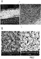
Figure 2 are scanning electron and optical images of a Li-free negative electrode with deposited layers. -
Figure 3 illustrates the initial charge of a solid-state cell with various Li-free negative electrodes (Current density 200 µA/cm2). -
Figure 3 illustrates a solid-state cell with a Li-free negative electrode based on a Zn layer + Bi layer, during continued cycling at high current densities during charge (Capacity -
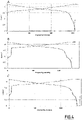
Figure 4 illustrates the charge - discharge profiles with increasing current densities of charge. -
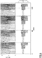
Figure 5 illustrates a solid-state cell with a Li-free negative electrode based on 3 metal layers Zn/Sn/Bi, during cycling with increasing current densities during charge and discharge. -
Figure 6 illustrates a solid-state cell with a Li-free negative electrode and increased loading/ Capacity 4.3 mAh/cm2 during cycling with increasing current densities. - The following examples are offered for illustration purposes and do not represent all possibilities encompassed by the present invention.
- A Li-free negative electrode was assembled as follows :
A layer of Zn which has lithiation potential 0.157 V vs metal Li was deposited directly on Cu current collector by electroplating and then, a layer of Bi which has lithiation potential 0.82 V vs metal Li was deposited on top of Zn layer by slurry coating of nanoparticles with size from 30 nm up to 100 nm, preferably 50nm. - Its initial structure and its change during cycling is illustrated in
Figure 1 . - In
Figure 1 , (A) depicts its initial structure, (B) depicts the structure after the 1st charge and (C) after the discharge, where (B) and (C) are reversibly achieved during the following cycling (D). - As illustrated in
Figure (1A ), a representative negative electrode in its initial stage comprises a current collector (1) in the form of a Cu foil, coated with the layer (1) depicted byfigure (2 )), which can comprise typically Zn. On the top of this layer is further coated the second layer (2) (depicted byfigure (3 )) which can typically be made of Bi. - During the first charge the initial Bi/Li alloy is formed at potential below 0.82V, after full lithiation of Bi the potential decreased to the level where the lithiation of Zn started. After that lithium is plated to current collector.
- After the first cycling (B), metal lithium is deposited on the current collector in the form of a metal layer (6), whereas the first and second layers are lithiated and comprise lithium alloys, said alloys being formed with their respective constitutive metals. The first layer (2) becomes thus lithiated into alloy layer (5), and the second layer (3) becomes lithiated alloy layer (4).
- After discharge (C), the layer (6) of metal lithium is substantially consumed, and the first and second layers (5) and (6) substantially unchanged or becomes partially lithiated if all metal lithium is consumed.
- The structures depicted in (B) and (C) are obtained reversibly after each cycling.
- On
Figure 2A , it is apparent that the current collector (Cu foil) (1) is coated with deposited layers (7). OnFigure 2B , the surface of the initial Cu foil and the surface of the foil coated with the deposited layers are pictured (E and F, respectively). - The thickness of each deposited layer is about 1 µm and it is enough to create layers of alloys that prevent lithium dendrite formation and prevent reactivity with electrolytes.
- Electrochemical cells were prepared with the negative electrodes with different configurations and compositions of layers (2) and (3) as depicted in
Figure 1 above, with a NMC positive electrode (Nickel Manganese Cobalt oxide), with a sulfide electrolyte and sulfide solid-state electrolyte as separator. - Cathode composite powder comprises a positive electrode active material (LiNi0.8Mn0.1 CO0.1O2), a sulfide-based solid electrolyte, and a conductive material at a mass ratio 70:25:5.
- A press die with ceramic liner and diameter 15 mm was used for electrochemical cells assembling. Initially 70-100 mg of the sulfide-based solid electrolyte powder was evenly spread inside the die and slightly pressed to form a dense pellet. After that, the cathode composite powder was added on one side in an amount corresponding to the required capacity (from 3 up to 4.5 mAh/cm2). A negative electrode disk was added on the opposite side of solid electrolyte pellet.
- Finally, the electrochemical sell was compacted by warm pressing at 4.6-5 ton/cm2 and temperature 60-100 °C for 5 min. The press die was fixed in fixture and electrochemical testing started at 20 °C with low current density at 1st cycle (200 µA/cm2).
- As apparent from
Figure 3A , during the first charge with relatively low current density (200 µA/cm2) the Copper foil as current collector without any additional layers creates dendrites almost immediately after about 2 hours (10 % of total charge time) or about 8 mAh/g when the cell potential starts to decreasing in result of partial short-circuit after reaching 3.6 V vs Li. - The coating of one layer of Zn on the top of the Cu foil (
Figure 3B ) improves the charge but does not solve the issue. The dendrites appeared only after 8 hours or 85 mAh/g of initial charge. - The addition of a further layer (Bi) on the top of the Zn layer creates a system described in example which fully solves the issue with dendrite formation (
Figure 3C ) : During the first charge, the characteristic for Bi plateau appeared and the cell can be charged without dendrite formation and charge and discharge capacities fully corresponded to amount of active material and its theoretical capacity without any evidence of dendrites formation. - It was further demonstrated that the negative electrode of the invention makes it possible to further increase the current densities during charge as apparent from
Figure 4 illustrates the charge - discharge profiles where current density of charge increased - ; 370 µA/cm2Fig.4a ; 568 µA/cm2Fig.4b ; and 1.1 mA/cm2Fig.4c respectively.Figure 4 demonstrates that the proposed 2 layers configuration not only prevents dendrite formation at low current densities but also gives possibility to increase current density and decrease charge time. - Negative electrodes were prepared according to two embodiments: either 3 layers (successive layers of Zn, Sn and Bi, respectively, in this order) or 2 layers (successive layers of Zn-Sn alloy and Bi, respectively, in this order) were coated on the current collector. In this case, the alloy layer may be obtained by the standard Eastwood Electroplating Tin-Zinc System.
- The two systems similarly protect the anode from dendrite formation
- Cells with negative electrodes with three layers (Zn+Sn alloy/Pb/Bi) NMC based cathodes and sulfide solid-state electrolyte were also prepared. The results illustrated in
Figures 5 and6 demonstrated that high current densities 3.2 mA/cm2 can be achieved at charge without dendrites formation for cells with high loading (4.3 mAh/cm2) and bigger amount of lithium transferred between electrodes during charge/discharge cycles. - Results are summarized in the table below:
I charge Current Density µA/cm2 Cell Capacity Q, mAh/cm2 Qcharge short circuit, mAh/cm2 # of cycles before short circuit Comment Cu 200 3.2 0.44 0 Short circuited during initial charge Cu/ Zn 200 3.2 2.9 0 Cu/ Bi 200 3.1 - 5-8 Short circuited during CV charge Cu/Zn/ Bi 200 3.1 - >300* Not Short circuited Cu/Zn/Bi 1100 4.3 - >300* Not Short circuited Cu/Zn/Sn/Bi and Cu/Zn+Sn alloy/Bi 2000 4.3 >300* Not Short circuited Cu/Zn+Sn alloy/Pb/Bi 3200 4.5 - >300* Not Short circuited * Cycleability is limited by cathode materials
Claims (16)
- A negative electrode of an electrochemical cell comprising :a current collector,a number (n) of successively coated layers over the surface of the current collector, the successive coated layers being numbered (i), i being comprised between 1 and n, in this order from the current collector surface, wherein the layer (1) is the closest layer respective to the current collector and the layer (n) is the furthest layer respective to the current collector;wherein n is an integer, equal to or greater than 2, and equal to or lower than 4,wherein the layer (n) has an outer face and an inner face on the opposite side,characterized in that each of the n coated layers, identical or different comprises one or more metals and/or metal alloys and/or metalloids and/or metalloid alloys, andin that the inner face of the layer (n) is in contact with the (n-1) layer immediately located beneath it.
- The negative electrode according to claim 1, which is initially lithium-free in that it does not comprise lithium before its first cycling.
- The negative electrode according to claim 1 or 2, which stores lithium after the first cycling :- in the form of a lithiated metal alloy within at least one of the coated layers and/or- in the form of a layer of elemental lithium coated between the current collector and the closest layer (1).
- The negative electrode according to anyone of the preceding claims wherein each layer comprises one or more metals and/or alloys and/or metalloids and/or metalloids alloys selected from Mg, Al, Zn, Cd, Ti, Cr, Mn, Co, Fe, Ag, Au, In, Sn, Pb, Bi, Sb, Si, B, and the alloys thereof.
- The negative electrode according to anyone of the preceding claims wherein the n layers are arranged so that layer (i+1) has a higher potential of lithiation than that of layer (i) which is immediately beneath it.
- The negative electrode according to anyone of the preceding claims wherein each layer has a thickness comprised between 0.05 and 20 µm, preferably between 0.2 and 10 µm.
- The negative electrode according to anyone of the preceding claims wherein n is 2.
- The negative electrode according to anyone of the preceding claims wherein the layer (n) comprises one or more metals selected from bismuth, indium, antimony and/or their alloys.
- The negative electrode according to anyone of the preceding claims wherein the layer (1) closest to the current comprises one or more metals selected from zinc, magnesium and/or their alloys.
- The negative electrode according to anyone of the preceding claims wherein the outer face of layer (n) has an increased surface area.
- The negative electrode according to anyone of the preceding claims wherein the current collector consists in a material or alloy chosen from the group consisting in copper, nickel, carbon, stainless steel, and the alloys thereof, in shape of foil, mesh, woven or non woven.
- Process of manufacture of the negative electrode according to anyone of the preceding claims wherein it comprises :- Coating the closest layer (1) on the current collector, and- successively coating each following coated layer (i) until layer (n) is coated, and wherein each coating step is identical or different.
- An electrochemical cell comprising :- A positive electrode ;- A negative electrode according to anyone of claims 1 to 11; and- A solid-state electrolyte layer as a separator between the positive and the negative electrodes.
- The electrochemical cell according to claim 13 which is a solid-state cell with sulfide-based electrolyte.
- An electrochemical module comprising at least two cells as defined in claim 13 or 14, each cell being electrically connected with one or more cell(s).
- A battery comprising at least 2 electrochemical cells according to claim 14 or 15 connected with each other, or one or more modules according to claim 15.
Priority Applications (3)
| Application Number | Priority Date | Filing Date | Title |
|---|---|---|---|
| EP20306510.7A EP4009394B1 (en) | 2020-12-07 | 2020-12-07 | Anti-dendrite negative electrodes, and the electrochemical cells containing them |
| US17/543,099 US20220181613A1 (en) | 2020-12-07 | 2021-12-06 | Anti-dendrite negative electrodes, and the electrochemical cells containing them |
| CN202111484306.5A CN114597334A (en) | 2020-12-07 | 2021-12-07 | Anti-dendritic negative electrode, and electrochemical cell containing the anti-dendritic negative electrode |
Applications Claiming Priority (1)
| Application Number | Priority Date | Filing Date | Title |
|---|---|---|---|
| EP20306510.7A EP4009394B1 (en) | 2020-12-07 | 2020-12-07 | Anti-dendrite negative electrodes, and the electrochemical cells containing them |
Publications (2)
| Publication Number | Publication Date |
|---|---|
| EP4009394A1 true EP4009394A1 (en) | 2022-06-08 |
| EP4009394B1 EP4009394B1 (en) | 2023-12-06 |
Family
ID=74591726
Family Applications (1)
| Application Number | Title | Priority Date | Filing Date |
|---|---|---|---|
| EP20306510.7A Active EP4009394B1 (en) | 2020-12-07 | 2020-12-07 | Anti-dendrite negative electrodes, and the electrochemical cells containing them |
Country Status (3)
| Country | Link |
|---|---|
| US (1) | US20220181613A1 (en) |
| EP (1) | EP4009394B1 (en) |
| CN (1) | CN114597334A (en) |
Cited By (1)
| Publication number | Priority date | Publication date | Assignee | Title |
|---|---|---|---|---|
| EP4485581A1 (en) * | 2023-06-26 | 2025-01-01 | Ningde Amperex Technology Limited | Secondary battery and electronic device |
Families Citing this family (4)
| Publication number | Priority date | Publication date | Assignee | Title |
|---|---|---|---|---|
| EP4053948A4 (en) * | 2019-10-29 | 2022-11-30 | Mitsui Mining & Smelting Co., Ltd. | SOLID ELECTROLYTE, AND MIXTURE OF ELECTRODES, SOLID ELECTROLYTE LAYER AND SOLID ELECTROLYTE BATTERY, EACH USING SUCH SOLID ELECTROLYTE |
| WO2024226683A1 (en) * | 2023-04-24 | 2024-10-31 | Solid Power Operating, Inc. | Hybrid anode and a solid-state battery cell made therefrom |
| KR102954913B1 (en) * | 2025-04-14 | 2026-04-21 | 주식회사 비이아이 | Anode-free lithium secondary battery having anode current collector coated with artificial sei layer, and method for manufacturing the same |
| KR102956622B1 (en) * | 2025-04-14 | 2026-04-23 | 주식회사 비이아이 | Anode-free lithium secondary battery having dual-coated anode current collector and methof for manufacturing the same |
Citations (3)
| Publication number | Priority date | Publication date | Assignee | Title |
|---|---|---|---|---|
| WO2019079258A2 (en) * | 2017-10-16 | 2019-04-25 | The Regents Of The University Of Colorado, A Body Corporate | Anode material - method of production and solid-state battery made therewith |
| US20200144599A1 (en) * | 2018-11-07 | 2020-05-07 | Samsung Electronics Co., Ltd. | Anodeless coating layer for all-solid-state battery and all-solid-state battery including anodeless coating layer |
| US20200176810A1 (en) | 2018-12-04 | 2020-06-04 | TeraWatt Technology Inc. | Anode-free solid-state battery cells with anti-dendrite and interface adhesion controlled functional layers |
Family Cites Families (7)
| Publication number | Priority date | Publication date | Assignee | Title |
|---|---|---|---|---|
| JP4619000B2 (en) * | 2001-07-27 | 2011-01-26 | マサチューセッツ インスティテュート オブ テクノロジー | Battery structure, self-organizing structure, and related method |
| US10211481B2 (en) * | 2014-11-26 | 2019-02-19 | Corning Incorporated | Stabilized solid garnet electrolyte and methods thereof |
| WO2020072524A1 (en) * | 2018-10-02 | 2020-04-09 | Quantumscape Corporation | Methods of making and using an electrochemical cell comprising an interlayer |
| CN111293352A (en) * | 2018-12-06 | 2020-06-16 | 三星电子株式会社 | All-solid-state secondary battery and method of manufacturing all-solid-state secondary battery |
| JP7319060B2 (en) * | 2019-02-27 | 2023-08-01 | 現代自動車株式会社 | All-solid battery |
| CN109994739B (en) * | 2019-03-25 | 2021-07-23 | 宁德新能源科技有限公司 | Negative pole piece and electrochemical device and electronic device including the same |
| EP3813161B1 (en) * | 2019-10-22 | 2023-09-06 | Samsung Electronics Co., Ltd. | All-solid secondary battery and method of manufacturing all-solid secondary battery |
-
2020
- 2020-12-07 EP EP20306510.7A patent/EP4009394B1/en active Active
-
2021
- 2021-12-06 US US17/543,099 patent/US20220181613A1/en not_active Abandoned
- 2021-12-07 CN CN202111484306.5A patent/CN114597334A/en active Pending
Patent Citations (3)
| Publication number | Priority date | Publication date | Assignee | Title |
|---|---|---|---|---|
| WO2019079258A2 (en) * | 2017-10-16 | 2019-04-25 | The Regents Of The University Of Colorado, A Body Corporate | Anode material - method of production and solid-state battery made therewith |
| US20200144599A1 (en) * | 2018-11-07 | 2020-05-07 | Samsung Electronics Co., Ltd. | Anodeless coating layer for all-solid-state battery and all-solid-state battery including anodeless coating layer |
| US20200176810A1 (en) | 2018-12-04 | 2020-06-04 | TeraWatt Technology Inc. | Anode-free solid-state battery cells with anti-dendrite and interface adhesion controlled functional layers |
Non-Patent Citations (2)
| Title |
|---|
| LEE ET AL., NATURE ENERGY, vol. 5, 2020, pages 299 - 308 |
| SUZUKI ET AL., ELECTROCHEMISTRY, vol. 74, no. 4, 2006, pages 303 - 308 |
Cited By (1)
| Publication number | Priority date | Publication date | Assignee | Title |
|---|---|---|---|---|
| EP4485581A1 (en) * | 2023-06-26 | 2025-01-01 | Ningde Amperex Technology Limited | Secondary battery and electronic device |
Also Published As
| Publication number | Publication date |
|---|---|
| US20220181613A1 (en) | 2022-06-09 |
| CN114597334A (en) | 2022-06-07 |
| EP4009394B1 (en) | 2023-12-06 |
Similar Documents
| Publication | Publication Date | Title |
|---|---|---|
| US11929463B2 (en) | All-solid-state secondary battery and method of charging the same | |
| KR102651551B1 (en) | Anode for all solid state secondary battery, all solid state secondary battery and method of manufacturing the same | |
| JP7614794B2 (en) | All-solid-state secondary battery | |
| EP4009394B1 (en) | Anti-dendrite negative electrodes, and the electrochemical cells containing them | |
| KR102871493B1 (en) | All solid lithium secondary battery and charging method for the same | |
| CN100474664C (en) | Anode and battery | |
| EP3961781A1 (en) | All-solid secondary battery | |
| KR102869287B1 (en) | Anodeless all solid state battery capable of operating at low temperature and manufacturing method thereof | |
| US20260074188A1 (en) | Anodeless all-solid-state battery including composite structure layer and manufacturing method thereof | |
| JP7284773B2 (en) | All-solid secondary battery | |
| JP2014225324A (en) | Nonaqueous electrolyte secondary cell | |
| EP4220750A1 (en) | Solid-state battery anode comprising polymer layer for preventing micro-short circuit, and solid-state battery comprising same | |
| US20230178716A1 (en) | Anode current collector including double coating layer and all-solid-state battery including same | |
| KR20230083459A (en) | All solid state battery having interlayer comprising metal sulfide | |
| JP2003263979A (en) | Non-aqueous electrolyte secondary battery and method of manufacturing the same | |
| JP7846503B2 (en) | All-solid-state secondary battery and charging method thereof | |
| US20230343930A1 (en) | Graphite/lithium hybrid negative electrode | |
| KR100359054B1 (en) | Metal oxide electrodes modified by conductive slurries and lithium secondary batteries | |
| KR20230084631A (en) | Lithium secondary battery with high durability and manufacturing method thereof | |
| KR20230037178A (en) | All solid-state battery comprising protective layer including metal sulfide and manufacturing method thereof | |
| US20250015342A1 (en) | All-solid-state battery including metal oxide and metal capable of alloying with lithium and a method of manufacturing the same | |
| KR102854279B1 (en) | All-solid-state lithium-ion secondary battery | |
| CN116569355B (en) | Lithium secondary battery | |
| WO2023145426A1 (en) | Battery and method for producing electrode | |
| KR20230060758A (en) | Anode for all solid state battery and manufacturing method thereof |
Legal Events
| Date | Code | Title | Description |
|---|---|---|---|
| PUAI | Public reference made under article 153(3) epc to a published international application that has entered the european phase |
Free format text: ORIGINAL CODE: 0009012 |
|
| STAA | Information on the status of an ep patent application or granted ep patent |
Free format text: STATUS: THE APPLICATION HAS BEEN PUBLISHED |
|
| AK | Designated contracting states |
Kind code of ref document: A1 Designated state(s): AL AT BE BG CH CY CZ DE DK EE ES FI FR GB GR HR HU IE IS IT LI LT LU LV MC MK MT NL NO PL PT RO RS SE SI SK SM TR |
|
| STAA | Information on the status of an ep patent application or granted ep patent |
Free format text: STATUS: REQUEST FOR EXAMINATION WAS MADE |
|
| 17P | Request for examination filed |
Effective date: 20220905 |
|
| RBV | Designated contracting states (corrected) |
Designated state(s): AL AT BE BG CH CY CZ DE DK EE ES FI FR GB GR HR HU IE IS IT LI LT LU LV MC MK MT NL NO PL PT RO RS SE SI SK SM TR |
|
| STAA | Information on the status of an ep patent application or granted ep patent |
Free format text: STATUS: EXAMINATION IS IN PROGRESS |
|
| 17Q | First examination report despatched |
Effective date: 20230126 |
|
| RIC1 | Information provided on ipc code assigned before grant |
Ipc: H01M 4/02 20060101ALN20230425BHEP Ipc: H01M 10/0562 20100101ALI20230425BHEP Ipc: H01M 10/0525 20100101ALI20230425BHEP Ipc: H01M 4/66 20060101ALI20230425BHEP Ipc: H01M 4/38 20060101ALI20230425BHEP Ipc: H01M 4/36 20060101ALI20230425BHEP Ipc: H01M 4/134 20100101ALI20230425BHEP Ipc: H01M 4/04 20060101AFI20230425BHEP |
|
| P01 | Opt-out of the competence of the unified patent court (upc) registered |
Effective date: 20230522 |
|
| GRAP | Despatch of communication of intention to grant a patent |
Free format text: ORIGINAL CODE: EPIDOSNIGR1 |
|
| RIC1 | Information provided on ipc code assigned before grant |
Ipc: H01M 4/02 20060101ALN20230612BHEP Ipc: H01M 10/0562 20100101ALI20230612BHEP Ipc: H01M 10/0525 20100101ALI20230612BHEP Ipc: H01M 4/66 20060101ALI20230612BHEP Ipc: H01M 4/38 20060101ALI20230612BHEP Ipc: H01M 4/36 20060101ALI20230612BHEP Ipc: H01M 4/134 20100101ALI20230612BHEP Ipc: H01M 4/04 20060101AFI20230612BHEP |
|
| STAA | Information on the status of an ep patent application or granted ep patent |
Free format text: STATUS: GRANT OF PATENT IS INTENDED |
|
| INTG | Intention to grant announced |
Effective date: 20230720 |
|
| GRAS | Grant fee paid |
Free format text: ORIGINAL CODE: EPIDOSNIGR3 |
|
| GRAA | (expected) grant |
Free format text: ORIGINAL CODE: 0009210 |
|
| STAA | Information on the status of an ep patent application or granted ep patent |
Free format text: STATUS: THE PATENT HAS BEEN GRANTED |
|
| AK | Designated contracting states |
Kind code of ref document: B1 Designated state(s): AL AT BE BG CH CY CZ DE DK EE ES FI FR GB GR HR HU IE IS IT LI LT LU LV MC MK MT NL NO PL PT RO RS SE SI SK SM TR |
|
| REG | Reference to a national code |
Ref country code: GB Ref legal event code: FG4D |
|
| REG | Reference to a national code |
Ref country code: CH Ref legal event code: EP |
|
| REG | Reference to a national code |
Ref country code: DE Ref legal event code: R096 Ref document number: 602020022256 Country of ref document: DE |
|
| REG | Reference to a national code |
Ref country code: IE Ref legal event code: FG4D |
|
| REG | Reference to a national code |
Ref country code: LT Ref legal event code: MG9D |
|
| PG25 | Lapsed in a contracting state [announced via postgrant information from national office to epo] |
Ref country code: GR Free format text: LAPSE BECAUSE OF FAILURE TO SUBMIT A TRANSLATION OF THE DESCRIPTION OR TO PAY THE FEE WITHIN THE PRESCRIBED TIME-LIMIT Effective date: 20240307 |
|
| REG | Reference to a national code |
Ref country code: NL Ref legal event code: MP Effective date: 20231206 |
|
| PG25 | Lapsed in a contracting state [announced via postgrant information from national office to epo] |
Ref country code: LT Free format text: LAPSE BECAUSE OF FAILURE TO SUBMIT A TRANSLATION OF THE DESCRIPTION OR TO PAY THE FEE WITHIN THE PRESCRIBED TIME-LIMIT Effective date: 20231206 |
|
| PG25 | Lapsed in a contracting state [announced via postgrant information from national office to epo] |
Ref country code: ES Free format text: LAPSE BECAUSE OF FAILURE TO SUBMIT A TRANSLATION OF THE DESCRIPTION OR TO PAY THE FEE WITHIN THE PRESCRIBED TIME-LIMIT Effective date: 20231206 |
|
| PG25 | Lapsed in a contracting state [announced via postgrant information from national office to epo] |
Ref country code: LT Free format text: LAPSE BECAUSE OF FAILURE TO SUBMIT A TRANSLATION OF THE DESCRIPTION OR TO PAY THE FEE WITHIN THE PRESCRIBED TIME-LIMIT Effective date: 20231206 Ref country code: GR Free format text: LAPSE BECAUSE OF FAILURE TO SUBMIT A TRANSLATION OF THE DESCRIPTION OR TO PAY THE FEE WITHIN THE PRESCRIBED TIME-LIMIT Effective date: 20240307 Ref country code: ES Free format text: LAPSE BECAUSE OF FAILURE TO SUBMIT A TRANSLATION OF THE DESCRIPTION OR TO PAY THE FEE WITHIN THE PRESCRIBED TIME-LIMIT Effective date: 20231206 Ref country code: BG Free format text: LAPSE BECAUSE OF FAILURE TO SUBMIT A TRANSLATION OF THE DESCRIPTION OR TO PAY THE FEE WITHIN THE PRESCRIBED TIME-LIMIT Effective date: 20240306 |
|
| REG | Reference to a national code |
Ref country code: AT Ref legal event code: MK05 Ref document number: 1639261 Country of ref document: AT Kind code of ref document: T Effective date: 20231206 |
|
| PG25 | Lapsed in a contracting state [announced via postgrant information from national office to epo] |
Ref country code: NL Free format text: LAPSE BECAUSE OF FAILURE TO SUBMIT A TRANSLATION OF THE DESCRIPTION OR TO PAY THE FEE WITHIN THE PRESCRIBED TIME-LIMIT Effective date: 20231206 |
|
| PG25 | Lapsed in a contracting state [announced via postgrant information from national office to epo] |
Ref country code: SE Free format text: LAPSE BECAUSE OF FAILURE TO SUBMIT A TRANSLATION OF THE DESCRIPTION OR TO PAY THE FEE WITHIN THE PRESCRIBED TIME-LIMIT Effective date: 20231206 Ref country code: RS Free format text: LAPSE BECAUSE OF FAILURE TO SUBMIT A TRANSLATION OF THE DESCRIPTION OR TO PAY THE FEE WITHIN THE PRESCRIBED TIME-LIMIT Effective date: 20231206 Ref country code: NO Free format text: LAPSE BECAUSE OF FAILURE TO SUBMIT A TRANSLATION OF THE DESCRIPTION OR TO PAY THE FEE WITHIN THE PRESCRIBED TIME-LIMIT Effective date: 20240306 Ref country code: NL Free format text: LAPSE BECAUSE OF FAILURE TO SUBMIT A TRANSLATION OF THE DESCRIPTION OR TO PAY THE FEE WITHIN THE PRESCRIBED TIME-LIMIT Effective date: 20231206 Ref country code: LV Free format text: LAPSE BECAUSE OF FAILURE TO SUBMIT A TRANSLATION OF THE DESCRIPTION OR TO PAY THE FEE WITHIN THE PRESCRIBED TIME-LIMIT Effective date: 20231206 Ref country code: HR Free format text: LAPSE BECAUSE OF FAILURE TO SUBMIT A TRANSLATION OF THE DESCRIPTION OR TO PAY THE FEE WITHIN THE PRESCRIBED TIME-LIMIT Effective date: 20231206 |
|
| PG25 | Lapsed in a contracting state [announced via postgrant information from national office to epo] |
Ref country code: IS Free format text: LAPSE BECAUSE OF FAILURE TO SUBMIT A TRANSLATION OF THE DESCRIPTION OR TO PAY THE FEE WITHIN THE PRESCRIBED TIME-LIMIT Effective date: 20240406 |
|
| PG25 | Lapsed in a contracting state [announced via postgrant information from national office to epo] |
Ref country code: CZ Free format text: LAPSE BECAUSE OF FAILURE TO SUBMIT A TRANSLATION OF THE DESCRIPTION OR TO PAY THE FEE WITHIN THE PRESCRIBED TIME-LIMIT Effective date: 20231206 Ref country code: AT Free format text: LAPSE BECAUSE OF FAILURE TO SUBMIT A TRANSLATION OF THE DESCRIPTION OR TO PAY THE FEE WITHIN THE PRESCRIBED TIME-LIMIT Effective date: 20231206 |
|
| PG25 | Lapsed in a contracting state [announced via postgrant information from national office to epo] |
Ref country code: SK Free format text: LAPSE BECAUSE OF FAILURE TO SUBMIT A TRANSLATION OF THE DESCRIPTION OR TO PAY THE FEE WITHIN THE PRESCRIBED TIME-LIMIT Effective date: 20231206 |
|
| PG25 | Lapsed in a contracting state [announced via postgrant information from national office to epo] |
Ref country code: SM Free format text: LAPSE BECAUSE OF FAILURE TO SUBMIT A TRANSLATION OF THE DESCRIPTION OR TO PAY THE FEE WITHIN THE PRESCRIBED TIME-LIMIT Effective date: 20231206 Ref country code: SK Free format text: LAPSE BECAUSE OF FAILURE TO SUBMIT A TRANSLATION OF THE DESCRIPTION OR TO PAY THE FEE WITHIN THE PRESCRIBED TIME-LIMIT Effective date: 20231206 Ref country code: RO Free format text: LAPSE BECAUSE OF FAILURE TO SUBMIT A TRANSLATION OF THE DESCRIPTION OR TO PAY THE FEE WITHIN THE PRESCRIBED TIME-LIMIT Effective date: 20231206 Ref country code: IT Free format text: LAPSE BECAUSE OF FAILURE TO SUBMIT A TRANSLATION OF THE DESCRIPTION OR TO PAY THE FEE WITHIN THE PRESCRIBED TIME-LIMIT Effective date: 20231206 Ref country code: IS Free format text: LAPSE BECAUSE OF FAILURE TO SUBMIT A TRANSLATION OF THE DESCRIPTION OR TO PAY THE FEE WITHIN THE PRESCRIBED TIME-LIMIT Effective date: 20240406 Ref country code: EE Free format text: LAPSE BECAUSE OF FAILURE TO SUBMIT A TRANSLATION OF THE DESCRIPTION OR TO PAY THE FEE WITHIN THE PRESCRIBED TIME-LIMIT Effective date: 20231206 Ref country code: CZ Free format text: LAPSE BECAUSE OF FAILURE TO SUBMIT A TRANSLATION OF THE DESCRIPTION OR TO PAY THE FEE WITHIN THE PRESCRIBED TIME-LIMIT Effective date: 20231206 Ref country code: AT Free format text: LAPSE BECAUSE OF FAILURE TO SUBMIT A TRANSLATION OF THE DESCRIPTION OR TO PAY THE FEE WITHIN THE PRESCRIBED TIME-LIMIT Effective date: 20231206 |
|
| REG | Reference to a national code |
Ref country code: CH Ref legal event code: PL |
|
| PG25 | Lapsed in a contracting state [announced via postgrant information from national office to epo] |
Ref country code: PL Free format text: LAPSE BECAUSE OF FAILURE TO SUBMIT A TRANSLATION OF THE DESCRIPTION OR TO PAY THE FEE WITHIN THE PRESCRIBED TIME-LIMIT Effective date: 20231206 Ref country code: PT Free format text: LAPSE BECAUSE OF FAILURE TO SUBMIT A TRANSLATION OF THE DESCRIPTION OR TO PAY THE FEE WITHIN THE PRESCRIBED TIME-LIMIT Effective date: 20240408 |
|
| PG25 | Lapsed in a contracting state [announced via postgrant information from national office to epo] |
Ref country code: LU Free format text: LAPSE BECAUSE OF NON-PAYMENT OF DUE FEES Effective date: 20231207 |
|
| REG | Reference to a national code |
Ref country code: BE Ref legal event code: MM Effective date: 20231231 |
|
| PG25 | Lapsed in a contracting state [announced via postgrant information from national office to epo] |
Ref country code: PT Free format text: LAPSE BECAUSE OF FAILURE TO SUBMIT A TRANSLATION OF THE DESCRIPTION OR TO PAY THE FEE WITHIN THE PRESCRIBED TIME-LIMIT Effective date: 20240408 Ref country code: PL Free format text: LAPSE BECAUSE OF FAILURE TO SUBMIT A TRANSLATION OF THE DESCRIPTION OR TO PAY THE FEE WITHIN THE PRESCRIBED TIME-LIMIT Effective date: 20231206 Ref country code: LU Free format text: LAPSE BECAUSE OF NON-PAYMENT OF DUE FEES Effective date: 20231207 |
|
| REG | Reference to a national code |
Ref country code: DE Ref legal event code: R097 Ref document number: 602020022256 Country of ref document: DE |
|
| PG25 | Lapsed in a contracting state [announced via postgrant information from national office to epo] |
Ref country code: MC Free format text: LAPSE BECAUSE OF FAILURE TO SUBMIT A TRANSLATION OF THE DESCRIPTION OR TO PAY THE FEE WITHIN THE PRESCRIBED TIME-LIMIT Effective date: 20231206 |
|
| REG | Reference to a national code |
Ref country code: IE Ref legal event code: MM4A |
|
| PG25 | Lapsed in a contracting state [announced via postgrant information from national office to epo] |
Ref country code: IE Free format text: LAPSE BECAUSE OF NON-PAYMENT OF DUE FEES Effective date: 20231207 |
|
| PG25 | Lapsed in a contracting state [announced via postgrant information from national office to epo] |
Ref country code: DK Free format text: LAPSE BECAUSE OF FAILURE TO SUBMIT A TRANSLATION OF THE DESCRIPTION OR TO PAY THE FEE WITHIN THE PRESCRIBED TIME-LIMIT Effective date: 20231206 |
|
| PLBE | No opposition filed within time limit |
Free format text: ORIGINAL CODE: 0009261 |
|
| STAA | Information on the status of an ep patent application or granted ep patent |
Free format text: STATUS: NO OPPOSITION FILED WITHIN TIME LIMIT |
|
| PG25 | Lapsed in a contracting state [announced via postgrant information from national office to epo] |
Ref country code: BE Free format text: LAPSE BECAUSE OF NON-PAYMENT OF DUE FEES Effective date: 20231231 |
|
| PG25 | Lapsed in a contracting state [announced via postgrant information from national office to epo] |
Ref country code: CH Free format text: LAPSE BECAUSE OF NON-PAYMENT OF DUE FEES Effective date: 20231231 |
|
| PG25 | Lapsed in a contracting state [announced via postgrant information from national office to epo] |
Ref country code: SI Free format text: LAPSE BECAUSE OF FAILURE TO SUBMIT A TRANSLATION OF THE DESCRIPTION OR TO PAY THE FEE WITHIN THE PRESCRIBED TIME-LIMIT Effective date: 20231206 |
|
| PG25 | Lapsed in a contracting state [announced via postgrant information from national office to epo] |
Ref country code: SI Free format text: LAPSE BECAUSE OF FAILURE TO SUBMIT A TRANSLATION OF THE DESCRIPTION OR TO PAY THE FEE WITHIN THE PRESCRIBED TIME-LIMIT Effective date: 20231206 Ref country code: IE Free format text: LAPSE BECAUSE OF NON-PAYMENT OF DUE FEES Effective date: 20231207 Ref country code: DK Free format text: LAPSE BECAUSE OF FAILURE TO SUBMIT A TRANSLATION OF THE DESCRIPTION OR TO PAY THE FEE WITHIN THE PRESCRIBED TIME-LIMIT Effective date: 20231206 Ref country code: CH Free format text: LAPSE BECAUSE OF NON-PAYMENT OF DUE FEES Effective date: 20231231 Ref country code: BE Free format text: LAPSE BECAUSE OF NON-PAYMENT OF DUE FEES Effective date: 20231231 |
|
| 26N | No opposition filed |
Effective date: 20240909 |
|
| PG25 | Lapsed in a contracting state [announced via postgrant information from national office to epo] |
Ref country code: FI Free format text: LAPSE BECAUSE OF FAILURE TO SUBMIT A TRANSLATION OF THE DESCRIPTION OR TO PAY THE FEE WITHIN THE PRESCRIBED TIME-LIMIT Effective date: 20231207 |
|
| PG25 | Lapsed in a contracting state [announced via postgrant information from national office to epo] |
Ref country code: CY Free format text: LAPSE BECAUSE OF FAILURE TO SUBMIT A TRANSLATION OF THE DESCRIPTION OR TO PAY THE FEE WITHIN THE PRESCRIBED TIME-LIMIT; INVALID AB INITIO Effective date: 20201207 |
|
| PG25 | Lapsed in a contracting state [announced via postgrant information from national office to epo] |
Ref country code: HU Free format text: LAPSE BECAUSE OF FAILURE TO SUBMIT A TRANSLATION OF THE DESCRIPTION OR TO PAY THE FEE WITHIN THE PRESCRIBED TIME-LIMIT; INVALID AB INITIO Effective date: 20201207 |
|
| PG25 | Lapsed in a contracting state [announced via postgrant information from national office to epo] |
Ref country code: TR Free format text: LAPSE BECAUSE OF FAILURE TO SUBMIT A TRANSLATION OF THE DESCRIPTION OR TO PAY THE FEE WITHIN THE PRESCRIBED TIME-LIMIT Effective date: 20231206 |
|
| PGFP | Annual fee paid to national office [announced via postgrant information from national office to epo] |
Ref country code: GB Payment date: 20251229 Year of fee payment: 6 |
|
| PGFP | Annual fee paid to national office [announced via postgrant information from national office to epo] |
Ref country code: FR Payment date: 20251114 Year of fee payment: 6 |
|
| PGFP | Annual fee paid to national office [announced via postgrant information from national office to epo] |
Ref country code: DE Payment date: 20251231 Year of fee payment: 6 |