EP4009230B1 - Current waveform fluctuation starting point identification method, electronic device and readable storage medium - Google Patents
Current waveform fluctuation starting point identification method, electronic device and readable storage medium Download PDFInfo
- Publication number
- EP4009230B1 EP4009230B1 EP20859284.0A EP20859284A EP4009230B1 EP 4009230 B1 EP4009230 B1 EP 4009230B1 EP 20859284 A EP20859284 A EP 20859284A EP 4009230 B1 EP4009230 B1 EP 4009230B1
- Authority
- EP
- European Patent Office
- Prior art keywords
- waveform
- value
- fluctuation
- total current
- identifying
- Prior art date
- Legal status (The legal status is an assumption and is not a legal conclusion. Google has not performed a legal analysis and makes no representation as to the accuracy of the status listed.)
- Active
Links
Images

Classifications
-
- G—PHYSICS
- G21—NUCLEAR PHYSICS; NUCLEAR ENGINEERING
- G21D—NUCLEAR POWER PLANT
- G21D3/00—Control of nuclear power plant
- G21D3/001—Computer implemented control
-
- G—PHYSICS
- G21—NUCLEAR PHYSICS; NUCLEAR ENGINEERING
- G21D—NUCLEAR POWER PLANT
- G21D3/00—Control of nuclear power plant
- G21D3/08—Regulation of any parameters in the plant
-
- G—PHYSICS
- G06—COMPUTING OR CALCULATING; COUNTING
- G06F—ELECTRIC DIGITAL DATA PROCESSING
- G06F2218/00—Aspects of pattern recognition specially adapted for signal processing
- G06F2218/08—Feature extraction
- G06F2218/10—Feature extraction by analysing the shape of a waveform, e.g. extracting parameters relating to peaks
-
- Y—GENERAL TAGGING OF NEW TECHNOLOGICAL DEVELOPMENTS; GENERAL TAGGING OF CROSS-SECTIONAL TECHNOLOGIES SPANNING OVER SEVERAL SECTIONS OF THE IPC; TECHNICAL SUBJECTS COVERED BY FORMER USPC CROSS-REFERENCE ART COLLECTIONS [XRACs] AND DIGESTS
- Y02—TECHNOLOGIES OR APPLICATIONS FOR MITIGATION OR ADAPTATION AGAINST CLIMATE CHANGE
- Y02E—REDUCTION OF GREENHOUSE GAS [GHG] EMISSIONS, RELATED TO ENERGY GENERATION, TRANSMISSION OR DISTRIBUTION
- Y02E30/00—Energy generation of nuclear origin
Definitions
- the invention relates to a signal waveform identification technology, in particular to a technology capable of effectively identifying a fluctuation start point of a current waveform of a coil current in a control rod drive mechanism of a nuclear power plant.
- control rods are usually clustered as a temperature rod cluster, a power rod cluster, a shutdown rod cluster, for example, according to different positions and functions of the control rods in the core.
- Four control rods in the same cluster are arranged symmetrically in the reactor core (control rods in the center of the reactor core are a separate cluster), and linked while running.
- a control rod drive mechanism (electromagnetic coil, CRDM) is used to achieve the movements of the control rods such as lifting, inserting and holding, which is connected to the control rods through a drive rod assembly.
- the control rod drive mechanism adopts a stepwise magnetic lifting manner, and generally includes three electromagnetic coils, namely a lifting coil (LC), a movable gripper coil (MG coil), and a stationary gripper coil (SG coil).
- the electromagnetic coils and the yokes of the coil assembly and the iron core parts corresponding to the gripper assembly respectively constitute three electromagnets, namely a lifting electromagnet, a movable electromagnet and a stationary electromagnet, from top to bottom.
- the LC is excited to cause the lifting armature to attract thereby driving the movable gripper to advance a step pitch; while the LC is demagnetized to separate the lifting armature thereby driving the movable gripper to reset.
- the MG coil is excited to cause the movable armature to attract thereby driving the connecting rod to move upward, so that the movable gripper swings into the annular groove of the driving rod and then engages with the annular teeth of the driving rod; while the MG coil is demagnetized to separate the movable armature to drive the connecting rod to descend, so that the movable gripper swings out of the annular groove of the driving rod and then disengages from the annular teeth of the driving rod.
- the SG coil is excited to cause the stationary armature to attract thereby driving the connecting rod to move upward, so that the stationary gripper swings into the annular groove of the driving rod and then engages with the annular teeth of the driving rod; while the SG coil is demagnetized to separate the stationary armature thereby driving the connecting rod to descend, so that the stationary gripper swings out of the annular groove of the driving rod and then disengages from the annular teeth of the driving rod.
- the control system of control rods sends different currents to the three electromagnetic coils in the preset sequence to control the excitation and demagnetization of the coils, so that the core components of the three electromagnets in the corresponding gripper assembly run to control the motions of the driving rods thereby controlling the control rods to be lifted, inserted or stationary.
- the control rods may be out of control and there will be failures such as rod disengagement or rod dropping. Therefore, it is necessary to monitor the action time of the gripper during the whole process of lifting and inserting rods, that is, it's critical to calculate the start time and end time of the gripper action. Especially, it's required to accurately identify the start point of the coil current.
- Chinese application CN200610145682.0 discloses a method of waveform identification in signal processing, which relies on existing signal data to identify waveforms. Such a method compares the type and amplitude of the signal edge with the corresponding stored waveform to determine whether the signal edge is valid so as to calculate the pulse width, which is difficult to accurately determine a start point of a rising or falling waveform however.
- Chinese application CN201210001045.1 discloses a waveform identification method based on the waveform library of characteristic operating conditions of high-speed rail running. The method relies on the waveform library of characteristic operating conditions to analyze abnormal waveforms, and also needs to be established on the basis of a large number of original waveforms to identify existing waveforms. It's difficult to accurately determine a start point of a rising or falling waveform.
- US 5,999,583 A discloses a method and apparatus for control rod drive mechanism analysis using coil current signals.
- US 4,125,432 A discloses a method and apparatus for operating magnetic stepping-type mechanisms for nuclear reactor control rods.
- CN 1968228 A discloses a method for waveform recognition in signal processing.
- Objectives of the invention are to provide an identification method of a fluctuation start point in a current waveform, an electronic device, and a readable storage medium, which can accurately identify the position of the fluctuation start point in the waveform, and obtain a quick identification speed.
- the method of the present invention firstly identifies and extracts a fluctuant waveform segment in the total current waveform, and then compares the value of each data point in the fluctuant waveform segment with the value of the stationary waveform segment in front of the fluctuant waveform segment to determine an abnormal point with large fluctuation, and then backward searches a start point of such a fluctuation from the abnormal point.
- values in the stationary waveform segment are considered as the reference values of the fluctuant waveform segment, which can not only effectively eliminate other interferences such as data acquisition, but also make the reference values change with the change of the interference environment, thus the result is accurate.
- the method of firstly searching a first data point with abnormal fluctuation then backward searching the start point of the fluctuation has a fast calculation speed and an identification speed since there is no need to calculate a difference between each data point and the previous data point.
- a method 100 for identifying a fluctuation start point in a current waveform includes the following steps: (11) obtaining a total current waveform; (12) identifying and extracting a fluctuant waveform segment in the total current waveform and a stationary waveform segment that is closed to and located in front of the fluctuant waveform segment; (13) calculating a mean value of each data point in the stationary waveform segment, a difference value A between each data point and the mean value, and a difference value B between two adjacent data points, calculating an average fluctuation limit value according to the difference value A, and calculating an adjacent fluctuation limit value according to the difference value B; (14) calculating a value of each data point in the fluctuant waveform segment, sequentially searching forward from a front end of the fluctuant waveform segment and calculating a difference value C between each data point and the mean value, and taking a current data point as a first data point W(as shown in FIG.
- the fluctuant waveform segment can be a rising waveform segment or a falling waveform segment.
- the current waveform is a waveform of a coil current in a control rod drive mechanism of a nuclear power plant.
- the method of obtaining a total current waveform in step (11) includes collecting a waveform of the coil current in the control rod drive mechanism of the nuclear power plant to obtain a sampling waveform, and performing low-pass filtering on the sampling waveform to obtain the total current waveform.
- the manner of calculating an average fluctuation limit value according to the difference value A in step (13) includes multiplying the difference value A by a first preset coefficient to obtain the average fluctuation limit value.
- the manner of calculating an adjacent fluctuation limit value according to the difference value B in step (13) includes counting a difference distribution of the difference value B to obtain a probability of each difference value B, calculating a value expectation according to the probability of each difference value B to obtain an expected fluctuation value, and obtaining the adjacent fluctuation limit value according to the expected fluctuation value.
- the sum of the probabilities of the difference values B that are less than or equal to the adjacent fluctuation limit value is greater than or equal to a preset percentage (for example, 85 percent, etc.).
- the manner of obtaining the adjacent fluctuation limit value according to the expected fluctuation value includes multiplying the expected fluctuation value by a second preset coefficient to obtain the adjacent fluctuation limit value.
- the above first preset coefficient and second preset coefficient can be determined from the historical waveform data, and the thresholds of the first preset coefficient and the second preset coefficient need to be smaller than a value that is obtained by dividing the maximum value of the corresponding waveform amplitude (difference A) by the mean value.
- the smaller threshold of the coefficient indicates that the start point Q is more closed to the stationary waveform segment.
- the method further includes searching a rising edge or a falling edge in a signal waveform according to a waveform variation tendency, determining whether an amplitude of the rising edge and the falling edge exceeds a preset amplitude, if yes, capturing a waveform segment with the rising edge or the falling edge and several data points behind the rising edge or the falling edge as the fluctuant waveform segment.
- the number of the above-mentioned several data points is determined by the technicians according to the first preset coefficient. In this embodiment, the number of ranging 100-300 data points is selected.
- the manner of identifying a fluctuant waveform segment in the total current waveform includes sequentially indexing five data points (or other data points greater than or equal to three) in all data points in the total current waveform, if the five data points are sequentially increased or decreased, and the variation amplitude between the 5th data point and the 1st data point exceeds a preset range (for example, 0.2, or other values according to actual needs), then recognizing a rising waveform or a falling waveform corresponding to the waveform, and capturing the waveform segment with 150 data points behind the current five data points as the fluctuant waveform segment.
- a preset range for example, 0.2, or other values according to actual needs
- other methods may be used to recognize the fluctuant waveform segment, which is not limited.
- the manner of identifying and extracting a stationary waveform segment that is closed to and located in front of the fluctuant waveform segment includes capturing a waveform segment with 50 data points (or other data points greater than or equal to 10, and preferably between 30-100) in front of the current 5 data points as the stationary waveform segment.
- a waveform segment with several data points in front of certain data points at the front end of the fluctuant waveform segment may be captured as the stationary waveform segment.
- a waveform segment with 50 data points in front of the two data points at the front end of the fluctuant waveform segment is captured as the stationary waveform segment.
- the stationary waveform segment and the fluctuant waveform segment may be spaced with a few data points, or adjacent one another without any data point.
- the present invention also discloses an electronic device 200 including an acquisition device 24, one or more processors 21, a memory 22, and one or more programs 23.
- the one or more programs 23 are stored in the memory 22 and configured to be implemented by one or more processors 21.
- the acquisition device 24 is configured to acquire the coil current
- the processor 21 is connected to the acquisition device 24 to obtain the coil current
- a total current waveform is generated according to the coil current.
- the programs 23 include instructions for executing the method of identifying a fluctuation start point in a current waveform 100 as described above.
Landscapes
- Engineering & Computer Science (AREA)
- Physics & Mathematics (AREA)
- General Engineering & Computer Science (AREA)
- Plasma & Fusion (AREA)
- High Energy & Nuclear Physics (AREA)
- Measurement Of Current Or Voltage (AREA)
- Monitoring And Testing Of Nuclear Reactors (AREA)
- Measurement And Recording Of Electrical Phenomena And Electrical Characteristics Of The Living Body (AREA)
Description
- The invention relates to a signal waveform identification technology, in particular to a technology capable of effectively identifying a fluctuation start point of a current waveform of a coil current in a control rod drive mechanism of a nuclear power plant.
- During start-up, power conversion and shutdown of the nuclear power plant, the reactivity of the reactor is controlled by controlling the movements of the control rods such as lifting, inserting and holding, so as to ensure that the reactor is always in a controlled state. The control rods are usually clustered as a temperature rod cluster, a power rod cluster, a shutdown rod cluster, for example, according to different positions and functions of the control rods in the core. Four control rods in the same cluster are arranged symmetrically in the reactor core (control rods in the center of the reactor core are a separate cluster), and linked while running.
- A control rod drive mechanism (electromagnetic coil, CRDM) is used to achieve the movements of the control rods such as lifting, inserting and holding, which is connected to the control rods through a drive rod assembly. Generally, the control rod drive mechanism adopts a stepwise magnetic lifting manner, and generally includes three electromagnetic coils, namely a lifting coil (LC), a movable gripper coil (MG coil), and a stationary gripper coil (SG coil). The electromagnetic coils and the yokes of the coil assembly and the iron core parts corresponding to the gripper assembly respectively constitute three electromagnets, namely a lifting electromagnet, a movable electromagnet and a stationary electromagnet, from top to bottom. Specifically, the LC is excited to cause the lifting armature to attract thereby driving the movable gripper to advance a step pitch; while the LC is demagnetized to separate the lifting armature thereby driving the movable gripper to reset. The MG coil is excited to cause the movable armature to attract thereby driving the connecting rod to move upward, so that the movable gripper swings into the annular groove of the driving rod and then engages with the annular teeth of the driving rod; while the MG coil is demagnetized to separate the movable armature to drive the connecting rod to descend, so that the movable gripper swings out of the annular groove of the driving rod and then disengages from the annular teeth of the driving rod. The SG coil is excited to cause the stationary armature to attract thereby driving the connecting rod to move upward, so that the stationary gripper swings into the annular groove of the driving rod and then engages with the annular teeth of the driving rod; while the SG coil is demagnetized to separate the stationary armature thereby driving the connecting rod to descend, so that the stationary gripper swings out of the annular groove of the driving rod and then disengages from the annular teeth of the driving rod.
- The control system of control rods sends different currents to the three electromagnetic coils in the preset sequence to control the excitation and demagnetization of the coils, so that the core components of the three electromagnets in the corresponding gripper assembly run to control the motions of the driving rods thereby controlling the control rods to be lifted, inserted or stationary. As known, once the action time of gripper fails, the control rods may be out of control and there will be failures such as rod disengagement or rod dropping. Therefore, it is necessary to monitor the action time of the gripper during the whole process of lifting and inserting rods, that is, it's critical to calculate the start time and end time of the gripper action. Especially, it's required to accurately identify the start point of the coil current.
- Chinese application
CN200610145682.0 - Chinese application
CN201210001045.1
US 5,999,583 A discloses a method and apparatus for control rod drive mechanism analysis using coil current signals.
US 4,125,432 A discloses a method and apparatus for operating magnetic stepping-type mechanisms for nuclear reactor control rods.
CN 1968228 A discloses a method for waveform recognition in signal processing. - Therefore, there is an urgent need for a current waveform algorithm to accurately determine a start point of a fluctuation in a waveform which can solve the above problems.
- The invention is set out in the appended claims. Objectives of the invention are to provide an identification method of a fluctuation start point in a current waveform, an electronic device, and a readable storage medium, which can accurately identify the position of the fluctuation start point in the waveform, and obtain a quick identification speed.
- In comparison with the prior art, the method of the present invention firstly identifies and extracts a fluctuant waveform segment in the total current waveform, and then compares the value of each data point in the fluctuant waveform segment with the value of the stationary waveform segment in front of the fluctuant waveform segment to determine an abnormal point with large fluctuation, and then backward searches a start point of such a fluctuation from the abnormal point. In such a way, on the one hand, values in the stationary waveform segment are considered as the reference values of the fluctuant waveform segment, which can not only effectively eliminate other interferences such as data acquisition, but also make the reference values change with the change of the interference environment, thus the result is accurate. On the other hand, the method of firstly searching a first data point with abnormal fluctuation then backward searching the start point of the fluctuation has a fast calculation speed and an identification speed since there is no need to calculate a difference between each data point and the previous data point.
-
-
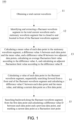
FIG. 1 is a flowchart of a method for identifying a fluctuation start point in a current waveform according to the present invention. -
FIG. 2 is a schematic diagram of a fluctuant waveform segment in the method for identifying a fluctuation start point in a current waveform according to the present invention. -
FIG. 3 is a structure diagram of an electronic device according to the present invention. - In order to describe the technical content, structural features, achieved objects and effects of the present invention in detail, the following detailed description is given in conjunction with the embodiments and the accompanying drawings.
- Referring to
FIG. 1 , amethod 100 for identifying a fluctuation start point in a current waveform according to the present invention includes the following steps: (11) obtaining a total current waveform; (12) identifying and extracting a fluctuant waveform segment in the total current waveform and a stationary waveform segment that is closed to and located in front of the fluctuant waveform segment; (13) calculating a mean value of each data point in the stationary waveform segment, a difference value A between each data point and the mean value, and a difference value B between two adjacent data points, calculating an average fluctuation limit value according to the difference value A, and calculating an adjacent fluctuation limit value according to the difference value B; (14) calculating a value of each data point in the fluctuant waveform segment, sequentially searching forward from a front end of the fluctuant waveform segment and calculating a difference value C between each data point and the mean value, and taking a current data point as a first data point W(as shown inFIG. 2 ) once the difference value C exceeds the average fluctuation limit value (namely the absolute value of the difference value C is greater than that of the mean fluctuation limit); and (15) searching backward along the fluctuant waveform segment from the first data point and calculating a difference value D between each data point and a previous data point, and marking a current data point as a fluctuation start point Q (as shown inFIG. 2 ) once the difference value D does not exceed the adjacent fluctuation limit value (namely, the absolute value of the difference value D is smaller than that of the adjacent fluctuation limit value). The fluctuant waveform segment can be a rising waveform segment or a falling waveform segment. - Specifically, the current waveform is a waveform of a coil current in a control rod drive mechanism of a nuclear power plant. The method of obtaining a total current waveform in step (11) includes collecting a waveform of the coil current in the control rod drive mechanism of the nuclear power plant to obtain a sampling waveform, and performing low-pass filtering on the sampling waveform to obtain the total current waveform.
- Specifically, the manner of calculating an average fluctuation limit value according to the difference value A in step (13) includes multiplying the difference value A by a first preset coefficient to obtain the average fluctuation limit value.
- Specifically, the manner of calculating an adjacent fluctuation limit value according to the difference value B in step (13) includes counting a difference distribution of the difference value B to obtain a probability of each difference value B, calculating a value expectation according to the probability of each difference value B to obtain an expected fluctuation value, and obtaining the adjacent fluctuation limit value according to the expected fluctuation value. In such a manner, the sum of the probabilities of the difference values B that are less than or equal to the adjacent fluctuation limit value is greater than or equal to a preset percentage (for example, 85 percent, etc.).
- Specifically, the manner of obtaining the adjacent fluctuation limit value according to the expected fluctuation value includes multiplying the expected fluctuation value by a second preset coefficient to obtain the adjacent fluctuation limit value.
- The above first preset coefficient and second preset coefficient can be determined from the historical waveform data, and the thresholds of the first preset coefficient and the second preset coefficient need to be smaller than a value that is obtained by dividing the maximum value of the corresponding waveform amplitude (difference A) by the mean value. The smaller threshold of the coefficient indicates that the start point Q is more closed to the stationary waveform segment.
- Preferably, the method further includes searching a rising edge or a falling edge in a signal waveform according to a waveform variation tendency, determining whether an amplitude of the rising edge and the falling edge exceeds a preset amplitude, if yes, capturing a waveform segment with the rising edge or the falling edge and several data points behind the rising edge or the falling edge as the fluctuant waveform segment. The number of the above-mentioned several data points is determined by the technicians according to the first preset coefficient. In this embodiment, the number of ranging 100-300 data points is selected.
- Specifically, the manner of identifying a fluctuant waveform segment in the total current waveform includes sequentially indexing five data points (or other data points greater than or equal to three) in all data points in the total current waveform, if the five data points are sequentially increased or decreased, and the variation amplitude between the 5th data point and the 1st data point exceeds a preset range (for example, 0.2, or other values according to actual needs), then recognizing a rising waveform or a falling waveform corresponding to the waveform, and capturing the waveform segment with 150 data points behind the current five data points as the fluctuant waveform segment. Optionally, other methods may be used to recognize the fluctuant waveform segment, which is not limited.
- Specifically, in step (12), the manner of identifying and extracting a stationary waveform segment that is closed to and located in front of the fluctuant waveform segment includes capturing a waveform segment with 50 data points (or other data points greater than or equal to 10, and preferably between 30-100) in front of the current 5 data points as the stationary waveform segment. In another embodiment, a waveform segment with several data points in front of certain data points at the front end of the fluctuant waveform segment may be captured as the stationary waveform segment. For example, a waveform segment with 50 data points in front of the two data points at the front end of the fluctuant waveform segment is captured as the stationary waveform segment. The stationary waveform segment and the fluctuant waveform segment may be spaced with a few data points, or adjacent one another without any data point.
- Referring to
FIG. 3 , the present invention also discloses anelectronic device 200 including anacquisition device 24, one ormore processors 21, amemory 22, and one ormore programs 23. The one ormore programs 23 are stored in thememory 22 and configured to be implemented by one ormore processors 21. Theacquisition device 24 is configured to acquire the coil current, theprocessor 21 is connected to theacquisition device 24 to obtain the coil current, and a total current waveform is generated according to the coil current. Theprograms 23 include instructions for executing the method of identifying a fluctuation start point in acurrent waveform 100 as described above.
Claims (9)
- A computer-implemented method (100) for identifying a fluctuation start point in a total current waveform, the total current waveform being a waveform of a coil current in a control rod drive mechanism of a nuclear power plant, wherein the method uses a computer to perform steps comprising:(1) obtaining (11) the total current waveform, identifying and extracting (12) a fluctuant waveform segment in the total current waveform and a stationary waveform segment that is close to and located in front of the fluctuant waveform segment; and
calculating (13) a mean value from each data point in the stationary waveform segment, and a difference value A between each data point and the mean value; and(2) calculating (14) a value of each data point in the fluctuant waveform segment;
characterised in that:step (1) further comprises:calculating a difference value B between two adjacent data points;calculating an average fluctuation limit value according to the difference value A; andcalculating an adjacent fluctuation limit value according to the difference value B;step (2) further comprises:sequentially searching forward from a front end of the fluctuant waveform segment and calculating a difference value C between each data point and the mean value, andtaking a current data point as a first data point once the difference value C exceeds the average fluctuation limit value; andthe method further comprises:(3) searching backward (15) along the fluctuant waveform segment from the first data point and calculating a difference value D between each data point and a previous data point, and
marking a current data point as a fluctuation start point once the difference value D does not exceed the adjacent fluctuation limit value. - The computer-implemented method for identifying a fluctuation start point in a total current waveform according to claim 1, wherein said calculating an average fluctuation limit value according to the difference value A in step (1) comprises multiplying the difference value A by a first preset coefficient to obtain the average fluctuation limit value.
- The computer-implemented method for identifying a fluctuation start point in a total current waveform according to claim 1, wherein said calculating an adjacent fluctuation limit value according to the difference value B comprises counting a difference distribution of the difference value B to obtain a probability of each difference value B, calculating a value expectation according to the probability of each difference value B to obtain an expected fluctuation value, and obtaining the adjacent fluctuation limit value according to the expected fluctuation value.
- The computer-implemented method for identifying a fluctuation start point in a total current waveform according to claim 3, wherein said obtaining the adjacent fluctuation limit value according to the expected fluctuation value comprises multiplying the expected fluctuation value by a second preset coefficient to obtain the adjacent fluctuation limit value.
- The computer-implemented method for identifying a fluctuation start point in a total current waveform according to claim 1, wherein said identifying a fluctuant waveform segment in the total current waveform comprises finding a rising edge or a falling edge in a signal waveform according to a waveform variation tendency, determining whether an amplitude of the rising edge and the falling edge exceeds a preset amplitude, if yes, capturing a waveform segment with the rising edge or the falling edge and preset data points behind the rising edge or the falling edge as the fluctuant waveform segment.
- The computer-implemented method for identifying a fluctuation start point in a total current waveform according to claim 1, wherein said identifying and extracting a stationary waveform segment that is close to and located in front of the fluctuant waveform segment comprises capturing a waveform segment with several data points located in front of a front end of the fluctuant waveform segment as the stationary waveform segment.
- The computer-implemented method for identifying a fluctuation start point in a total current waveform according to claim 1, wherein said obtaining the total current waveform comprises collecting a waveform of the coil current in the control rod drive mechanism of the nuclear power plant to obtain a sampling waveform, and performing low-pass filtering on the sampling waveform to obtain the total current waveform.
- An electronic device (200), comprising:an acquisition device (24), configured to collect a coil current in a control rod drive mechanism of a nuclear power plant;one or more processors (21), connected to the acquisition device to obtain the coil current, and configured to generate a total current waveform according to the coil current;a memory (22); andone or more programs (23), stored in the memory and configured to be executed by one or more processors, the programs comprising instructions for executing the computer-implemented method for identifying a fluctuation start point in a total current waveform according to any one of claims 1 -7.
- A computer-readable storage medium, comprising computer programs used in conjunction with an electronic device having a memory, wherein the computer programs are configured to be executed by a processor to perform the computer-implemented method for identifying a fluctuation start point in a current waveform according to any one of claims 1-7.
Applications Claiming Priority (2)
| Application Number | Priority Date | Filing Date | Title |
|---|---|---|---|
| CN201910804871.1A CN110503069B (en) | 2019-08-28 | 2019-08-28 | Current waveform fluctuation starting point identification method, electronic device and readable storage medium |
| PCT/CN2020/099057 WO2021036483A1 (en) | 2019-08-28 | 2020-06-30 | Current waveform fluctuation starting point identification method, electronic device and readable storage medium |
Publications (3)
| Publication Number | Publication Date |
|---|---|
| EP4009230A1 EP4009230A1 (en) | 2022-06-08 |
| EP4009230A4 EP4009230A4 (en) | 2022-10-12 |
| EP4009230B1 true EP4009230B1 (en) | 2025-02-12 |
Family
ID=68590216
Family Applications (1)
| Application Number | Title | Priority Date | Filing Date |
|---|---|---|---|
| EP20859284.0A Active EP4009230B1 (en) | 2019-08-28 | 2020-06-30 | Current waveform fluctuation starting point identification method, electronic device and readable storage medium |
Country Status (3)
| Country | Link |
|---|---|
| EP (1) | EP4009230B1 (en) |
| CN (1) | CN110503069B (en) |
| WO (1) | WO2021036483A1 (en) |
Families Citing this family (3)
| Publication number | Priority date | Publication date | Assignee | Title |
|---|---|---|---|---|
| CN110503069B (en) * | 2019-08-28 | 2022-10-18 | 中广核研究院有限公司 | Current waveform fluctuation starting point identification method, electronic device and readable storage medium |
| CN112911483B (en) * | 2021-01-22 | 2022-08-09 | 苏州华兴源创科技股份有限公司 | Interception method, device and storage medium for effective data starting point of feedback signal |
| CN117033918B (en) * | 2023-08-01 | 2024-06-11 | 珠海精实测控技术股份有限公司 | A waveform data segmentation processing method and device |
Family Cites Families (21)
| Publication number | Priority date | Publication date | Assignee | Title |
|---|---|---|---|---|
| US4125432A (en) * | 1977-01-24 | 1978-11-14 | Combustion Engineering, Inc. | Drive mechanism nuclear reactor control rod |
| US5999583A (en) * | 1996-04-29 | 1999-12-07 | Westinghouse Electric Company Llc | Method and apparatus for control rod drive mechanism analysis using coil current signals |
| CN100556014C (en) * | 2006-11-23 | 2009-10-28 | 中兴通讯股份有限公司 | A Method of Waveform Recognition in Signal Processing |
| JP5428720B2 (en) * | 2009-10-01 | 2014-02-26 | 三菱電機株式会社 | Method and apparatus for detecting position of mover of electromagnetic actuator |
| CN102542262B (en) * | 2012-01-04 | 2013-07-31 | 东南大学 | Waveform identification method based on operating-characteristic working condition waveform library of high-speed rail |
| US20150335948A1 (en) * | 2014-05-21 | 2015-11-26 | Rip Curl International Pty Ltd | Methods and Systems for Processing Sporting Performance Data |
| CN104052542B (en) * | 2014-06-23 | 2016-06-08 | 武汉光迅科技股份有限公司 | The method of OTDR curve end state event location breakpoints of optical fiber is detected under line model |
| CN107037247B (en) * | 2016-11-14 | 2019-03-15 | 丁大良 | A kind of recognition methods of digital signal |
| WO2018166136A1 (en) * | 2017-03-14 | 2018-09-20 | 华为技术有限公司 | Method and apparatus for processing waveform signal |
| CN107101984B (en) * | 2017-05-18 | 2019-11-08 | 广东顺德工业设计研究院(广东顺德创新设计研究院) | Signal waveform feature detection method, device, storage medium and computer equipment |
| CN107368779B (en) * | 2017-06-02 | 2020-05-29 | 河南辉煌科技股份有限公司 | A feature extraction method of switch operating current curve |
| CN107390034B (en) * | 2017-06-28 | 2019-01-08 | 北京金风科创风电设备有限公司 | The analysis method and device of impulse waveform amplitude variation |
| CN107389723B (en) * | 2017-07-31 | 2019-08-27 | 中国计量大学 | A method for judging the starting point of adiabatic reaction and tracking temperature based on temperature difference |
| US20190064223A1 (en) * | 2017-08-25 | 2019-02-28 | Keysight Technologies, Inc. | Method and Apparatus for Detecting the Start of an Event in the Presence of Noise |
| CN108152674B (en) * | 2017-12-21 | 2020-08-04 | 国网宁夏电力公司中卫供电公司 | A Fault Traveling Wave Filtering Method Based on Feature Point Identification and Linear Interpolation |
| CN108680783A (en) * | 2018-05-11 | 2018-10-19 | 中国核动力研究设计院 | The method for monitoring the oscillation of reactor control rod driving mechanism coil current failing edge |
| CN108647661A (en) * | 2018-05-17 | 2018-10-12 | 电子科技大学 | A kind of extracting method of complete cycle waveform |
| CN109061725B (en) * | 2018-06-22 | 2020-05-05 | 中国电建集团贵阳勘测设计研究院有限公司 | Automatic identification method of elastic wave data acquisition jumping point and equipment used by same |
| CN109374953B (en) * | 2018-12-14 | 2020-09-18 | 国网湖北省电力有限公司电力科学研究院 | Voltage sag waveform point detection method based on voltage effective value sequence |
| CN110083991A (en) * | 2019-05-28 | 2019-08-02 | 浙江长兴笛卡尔科技有限公司 | The armature of relay and contact start condition detection method, equipment and the medium of touching |
| CN110503069B (en) * | 2019-08-28 | 2022-10-18 | 中广核研究院有限公司 | Current waveform fluctuation starting point identification method, electronic device and readable storage medium |
-
2019
- 2019-08-28 CN CN201910804871.1A patent/CN110503069B/en active Active
-
2020
- 2020-06-30 EP EP20859284.0A patent/EP4009230B1/en active Active
- 2020-06-30 WO PCT/CN2020/099057 patent/WO2021036483A1/en not_active Ceased
Also Published As
| Publication number | Publication date |
|---|---|
| EP4009230A1 (en) | 2022-06-08 |
| CN110503069A (en) | 2019-11-26 |
| CN110503069B (en) | 2022-10-18 |
| EP4009230A4 (en) | 2022-10-12 |
| WO2021036483A1 (en) | 2021-03-04 |
Similar Documents
| Publication | Publication Date | Title |
|---|---|---|
| EP4009230A1 (en) | Current waveform fluctuation starting point identification method, electronic device and readable storage medium | |
| Blokland et al. | Uncertainty aware anomaly detection to predict errant beam pulses in the Oak Ridge Spallation Neutron Source accelerator | |
| CN106772009B (en) | Breaker mechanic property analysis method based on divide-shut brake coil current waveform | |
| CN108446632B (en) | Partial discharge pulse edge searching and partial discharge confirming method | |
| US20200019816A1 (en) | Classification method and classification device of indoor scene | |
| Huang et al. | Sap: Self-adaptive proposal model for temporal action detection based on reinforcement learning | |
| CN105933681B (en) | Sensitivity self-adapting regulation method towards Activity recognition | |
| CN109243644A (en) | Nuclear power plant's Dropping of control rod time detection method and electronic equipment | |
| CN112684329A (en) | Intelligent diagnosis method for mechanical fault of high-voltage circuit breaker | |
| CN112611309A (en) | Accurate measurement method for control rod position | |
| CN117991172B (en) | A voltage transformer with fault identification function | |
| EP4009335A1 (en) | Method for monitoring hook action of control rod driving mechanism of nuclear power station, and electronic device | |
| CN116338348B (en) | Multi-variable direct-current fault arc self-adaptive detection method based on similarity measurement and transfer learning | |
| CN120445650A (en) | A bearing fault identification method based on time series parameter statistics | |
| CN120254587A (en) | A small circuit breaker detection method and detection device | |
| CN119337057B (en) | Interference signal filtering method and system suitable for nuclear power plant control rod position measurement | |
| CN108680783A (en) | The method for monitoring the oscillation of reactor control rod driving mechanism coil current failing edge | |
| CN118981172B (en) | A switch jam diagnosis method, system and storage medium based on single chip microcomputer | |
| Huang et al. | A self-adaptive proposal model for temporal action detection based on reinforcement learning | |
| CN115206559B (en) | Control rod driving mechanism performance monitoring method, device, equipment and medium | |
| CN112098836B (en) | Motor unstable data elimination method and system based on electrical distortion analysis | |
| CN112986658A (en) | Topology identification method and device for low-voltage line | |
| CN121500081A (en) | A method, device, equipment, and storage medium for fault identification of opening and closing electromagnets. | |
| CN108646084A (en) | The method for monitoring the oscillation of reactor control rod driving mechanism coil current rising edge | |
| CN119813176A (en) | A method and device for identifying low voltage distribution network topology based on voltage similarity evaluation |
Legal Events
| Date | Code | Title | Description |
|---|---|---|---|
| STAA | Information on the status of an ep patent application or granted ep patent |
Free format text: STATUS: THE INTERNATIONAL PUBLICATION HAS BEEN MADE |
|
| PUAI | Public reference made under article 153(3) epc to a published international application that has entered the european phase |
Free format text: ORIGINAL CODE: 0009012 |
|
| STAA | Information on the status of an ep patent application or granted ep patent |
Free format text: STATUS: REQUEST FOR EXAMINATION WAS MADE |
|
| 17P | Request for examination filed |
Effective date: 20220304 |
|
| AK | Designated contracting states |
Kind code of ref document: A1 Designated state(s): AL AT BE BG CH CY CZ DE DK EE ES FI FR GB GR HR HU IE IS IT LI LT LU LV MC MK MT NL NO PL PT RO RS SE SI SK SM TR |
|
| A4 | Supplementary search report drawn up and despatched |
Effective date: 20220909 |
|
| RIC1 | Information provided on ipc code assigned before grant |
Ipc: G06K 9/00 20220101ALI20220905BHEP Ipc: G21D 3/08 20060101AFI20220905BHEP |
|
| DAV | Request for validation of the european patent (deleted) | ||
| DAX | Request for extension of the european patent (deleted) | ||
| REG | Reference to a national code |
Ref country code: DE Ref legal event code: R079 Free format text: PREVIOUS MAIN CLASS: G06K0009000000 Ipc: G21D0003080000 Ref country code: DE Ref legal event code: R079 Ref document number: 602020046083 Country of ref document: DE Free format text: PREVIOUS MAIN CLASS: G06K0009000000 Ipc: G21D0003080000 |
|
| GRAP | Despatch of communication of intention to grant a patent |
Free format text: ORIGINAL CODE: EPIDOSNIGR1 |
|
| STAA | Information on the status of an ep patent application or granted ep patent |
Free format text: STATUS: GRANT OF PATENT IS INTENDED |
|
| RIC1 | Information provided on ipc code assigned before grant |
Ipc: G06F 18/10 20230101ALN20241106BHEP Ipc: G21D 3/08 20060101AFI20241106BHEP |
|
| INTG | Intention to grant announced |
Effective date: 20241121 |
|
| GRAS | Grant fee paid |
Free format text: ORIGINAL CODE: EPIDOSNIGR3 |
|
| GRAA | (expected) grant |
Free format text: ORIGINAL CODE: 0009210 |
|
| STAA | Information on the status of an ep patent application or granted ep patent |
Free format text: STATUS: THE PATENT HAS BEEN GRANTED |
|
| AK | Designated contracting states |
Kind code of ref document: B1 Designated state(s): AL AT BE BG CH CY CZ DE DK EE ES FI FR GB GR HR HU IE IS IT LI LT LU LV MC MK MT NL NO PL PT RO RS SE SI SK SM TR |
|
| REG | Reference to a national code |
Ref country code: GB Ref legal event code: FG4D |
|
| REG | Reference to a national code |
Ref country code: CH Ref legal event code: EP |
|
| REG | Reference to a national code |
Ref country code: DE Ref legal event code: R096 Ref document number: 602020046083 Country of ref document: DE |
|
| REG | Reference to a national code |
Ref country code: IE Ref legal event code: FG4D |
|
| REG | Reference to a national code |
Ref country code: NL Ref legal event code: MP Effective date: 20250212 |
|
| PG25 | Lapsed in a contracting state [announced via postgrant information from national office to epo] |
Ref country code: RS Free format text: LAPSE BECAUSE OF FAILURE TO SUBMIT A TRANSLATION OF THE DESCRIPTION OR TO PAY THE FEE WITHIN THE PRESCRIBED TIME-LIMIT Effective date: 20250512 |
|
| PG25 | Lapsed in a contracting state [announced via postgrant information from national office to epo] |
Ref country code: FI Free format text: LAPSE BECAUSE OF FAILURE TO SUBMIT A TRANSLATION OF THE DESCRIPTION OR TO PAY THE FEE WITHIN THE PRESCRIBED TIME-LIMIT Effective date: 20250212 |
|
| PG25 | Lapsed in a contracting state [announced via postgrant information from national office to epo] |
Ref country code: PL Free format text: LAPSE BECAUSE OF FAILURE TO SUBMIT A TRANSLATION OF THE DESCRIPTION OR TO PAY THE FEE WITHIN THE PRESCRIBED TIME-LIMIT Effective date: 20250212 |
|
| PG25 | Lapsed in a contracting state [announced via postgrant information from national office to epo] |
Ref country code: ES Free format text: LAPSE BECAUSE OF FAILURE TO SUBMIT A TRANSLATION OF THE DESCRIPTION OR TO PAY THE FEE WITHIN THE PRESCRIBED TIME-LIMIT Effective date: 20250212 |
|
| PGFP | Annual fee paid to national office [announced via postgrant information from national office to epo] |
Ref country code: GB Payment date: 20250523 Year of fee payment: 6 |
|
| REG | Reference to a national code |
Ref country code: LT Ref legal event code: MG9D |
|
| PG25 | Lapsed in a contracting state [announced via postgrant information from national office to epo] |
Ref country code: NO Free format text: LAPSE BECAUSE OF FAILURE TO SUBMIT A TRANSLATION OF THE DESCRIPTION OR TO PAY THE FEE WITHIN THE PRESCRIBED TIME-LIMIT Effective date: 20250512 Ref country code: IS Free format text: LAPSE BECAUSE OF FAILURE TO SUBMIT A TRANSLATION OF THE DESCRIPTION OR TO PAY THE FEE WITHIN THE PRESCRIBED TIME-LIMIT Effective date: 20250612 |
|
| PG25 | Lapsed in a contracting state [announced via postgrant information from national office to epo] |
Ref country code: NL Free format text: LAPSE BECAUSE OF FAILURE TO SUBMIT A TRANSLATION OF THE DESCRIPTION OR TO PAY THE FEE WITHIN THE PRESCRIBED TIME-LIMIT Effective date: 20250212 |
|
| PG25 | Lapsed in a contracting state [announced via postgrant information from national office to epo] |
Ref country code: HR Free format text: LAPSE BECAUSE OF FAILURE TO SUBMIT A TRANSLATION OF THE DESCRIPTION OR TO PAY THE FEE WITHIN THE PRESCRIBED TIME-LIMIT Effective date: 20250212 |
|
| PG25 | Lapsed in a contracting state [announced via postgrant information from national office to epo] |
Ref country code: PT Free format text: LAPSE BECAUSE OF FAILURE TO SUBMIT A TRANSLATION OF THE DESCRIPTION OR TO PAY THE FEE WITHIN THE PRESCRIBED TIME-LIMIT Effective date: 20250612 Ref country code: LV Free format text: LAPSE BECAUSE OF FAILURE TO SUBMIT A TRANSLATION OF THE DESCRIPTION OR TO PAY THE FEE WITHIN THE PRESCRIBED TIME-LIMIT Effective date: 20250212 |
|
| PGFP | Annual fee paid to national office [announced via postgrant information from national office to epo] |
Ref country code: FR Payment date: 20250523 Year of fee payment: 6 |
|
| PG25 | Lapsed in a contracting state [announced via postgrant information from national office to epo] |
Ref country code: GR Free format text: LAPSE BECAUSE OF FAILURE TO SUBMIT A TRANSLATION OF THE DESCRIPTION OR TO PAY THE FEE WITHIN THE PRESCRIBED TIME-LIMIT Effective date: 20250513 Ref country code: BG Free format text: LAPSE BECAUSE OF FAILURE TO SUBMIT A TRANSLATION OF THE DESCRIPTION OR TO PAY THE FEE WITHIN THE PRESCRIBED TIME-LIMIT Effective date: 20250212 |
|
| REG | Reference to a national code |
Ref country code: AT Ref legal event code: MK05 Ref document number: 1766899 Country of ref document: AT Kind code of ref document: T Effective date: 20250212 |
|
| PG25 | Lapsed in a contracting state [announced via postgrant information from national office to epo] |
Ref country code: SE Free format text: LAPSE BECAUSE OF FAILURE TO SUBMIT A TRANSLATION OF THE DESCRIPTION OR TO PAY THE FEE WITHIN THE PRESCRIBED TIME-LIMIT Effective date: 20250212 |
|
| PG25 | Lapsed in a contracting state [announced via postgrant information from national office to epo] |
Ref country code: SM Free format text: LAPSE BECAUSE OF FAILURE TO SUBMIT A TRANSLATION OF THE DESCRIPTION OR TO PAY THE FEE WITHIN THE PRESCRIBED TIME-LIMIT Effective date: 20250212 |
|
| PG25 | Lapsed in a contracting state [announced via postgrant information from national office to epo] |
Ref country code: DK Free format text: LAPSE BECAUSE OF FAILURE TO SUBMIT A TRANSLATION OF THE DESCRIPTION OR TO PAY THE FEE WITHIN THE PRESCRIBED TIME-LIMIT Effective date: 20250212 |
|
| PG25 | Lapsed in a contracting state [announced via postgrant information from national office to epo] |
Ref country code: IT Free format text: LAPSE BECAUSE OF FAILURE TO SUBMIT A TRANSLATION OF THE DESCRIPTION OR TO PAY THE FEE WITHIN THE PRESCRIBED TIME-LIMIT Effective date: 20250212 |
|
| PG25 | Lapsed in a contracting state [announced via postgrant information from national office to epo] |
Ref country code: AT Free format text: LAPSE BECAUSE OF FAILURE TO SUBMIT A TRANSLATION OF THE DESCRIPTION OR TO PAY THE FEE WITHIN THE PRESCRIBED TIME-LIMIT Effective date: 20250212 |
|
| PG25 | Lapsed in a contracting state [announced via postgrant information from national office to epo] |
Ref country code: EE Free format text: LAPSE BECAUSE OF FAILURE TO SUBMIT A TRANSLATION OF THE DESCRIPTION OR TO PAY THE FEE WITHIN THE PRESCRIBED TIME-LIMIT Effective date: 20250212 Ref country code: CZ Free format text: LAPSE BECAUSE OF FAILURE TO SUBMIT A TRANSLATION OF THE DESCRIPTION OR TO PAY THE FEE WITHIN THE PRESCRIBED TIME-LIMIT Effective date: 20250212 |
|
| PG25 | Lapsed in a contracting state [announced via postgrant information from national office to epo] |
Ref country code: RO Free format text: LAPSE BECAUSE OF FAILURE TO SUBMIT A TRANSLATION OF THE DESCRIPTION OR TO PAY THE FEE WITHIN THE PRESCRIBED TIME-LIMIT Effective date: 20250212 |
|
| PG25 | Lapsed in a contracting state [announced via postgrant information from national office to epo] |
Ref country code: SK Free format text: LAPSE BECAUSE OF FAILURE TO SUBMIT A TRANSLATION OF THE DESCRIPTION OR TO PAY THE FEE WITHIN THE PRESCRIBED TIME-LIMIT Effective date: 20250212 |
|
| REG | Reference to a national code |
Ref country code: DE Ref legal event code: R097 Ref document number: 602020046083 Country of ref document: DE |
|
| PLBE | No opposition filed within time limit |
Free format text: ORIGINAL CODE: 0009261 |
|
| STAA | Information on the status of an ep patent application or granted ep patent |
Free format text: STATUS: NO OPPOSITION FILED WITHIN TIME LIMIT |
|
| REG | Reference to a national code |
Ref country code: CH Ref legal event code: L10 Free format text: ST27 STATUS EVENT CODE: U-0-0-L10-L00 (AS PROVIDED BY THE NATIONAL OFFICE) Effective date: 20251224 |
|
| REG | Reference to a national code |
Ref country code: DE Ref legal event code: R119 Ref document number: 602020046083 Country of ref document: DE |
|
| 26N | No opposition filed |
Effective date: 20251113 |
|
| REG | Reference to a national code |
Ref country code: CH Ref legal event code: H13 Free format text: ST27 STATUS EVENT CODE: U-0-0-H10-H13 (AS PROVIDED BY THE NATIONAL OFFICE) Effective date: 20260127 |
|
| PG25 | Lapsed in a contracting state [announced via postgrant information from national office to epo] |
Ref country code: MC Free format text: LAPSE BECAUSE OF FAILURE TO SUBMIT A TRANSLATION OF THE DESCRIPTION OR TO PAY THE FEE WITHIN THE PRESCRIBED TIME-LIMIT Effective date: 20250212 |
|
| PG25 | Lapsed in a contracting state [announced via postgrant information from national office to epo] |
Ref country code: LU Free format text: LAPSE BECAUSE OF NON-PAYMENT OF DUE FEES Effective date: 20250630 |
|
| REG | Reference to a national code |
Ref country code: BE Ref legal event code: MM Effective date: 20250630 |
|
| PG25 | Lapsed in a contracting state [announced via postgrant information from national office to epo] |
Ref country code: IE Free format text: LAPSE BECAUSE OF NON-PAYMENT OF DUE FEES Effective date: 20250630 Ref country code: DE Free format text: LAPSE BECAUSE OF NON-PAYMENT OF DUE FEES Effective date: 20260101 |
|
| PG25 | Lapsed in a contracting state [announced via postgrant information from national office to epo] |
Ref country code: BE Free format text: LAPSE BECAUSE OF NON-PAYMENT OF DUE FEES Effective date: 20250630 |
|
| PG25 | Lapsed in a contracting state [announced via postgrant information from national office to epo] |
Ref country code: CH Free format text: LAPSE BECAUSE OF NON-PAYMENT OF DUE FEES Effective date: 20250630 |