EP4009141A2 - System and methods to reshape fan noise in electronic devices - Google Patents
System and methods to reshape fan noise in electronic devices Download PDFInfo
- Publication number
- EP4009141A2 EP4009141A2 EP21198568.4A EP21198568A EP4009141A2 EP 4009141 A2 EP4009141 A2 EP 4009141A2 EP 21198568 A EP21198568 A EP 21198568A EP 4009141 A2 EP4009141 A2 EP 4009141A2
- Authority
- EP
- European Patent Office
- Prior art keywords
- fan
- noise
- tone
- gain
- examples
- Prior art date
- Legal status (The legal status is an assumption and is not a legal conclusion. Google has not performed a legal analysis and makes no representation as to the accuracy of the status listed.)
- Granted
Links
Images





Classifications
-
- H—ELECTRICITY
- H04—ELECTRIC COMMUNICATION TECHNIQUE
- H04R—LOUDSPEAKERS, MICROPHONES, GRAMOPHONE PICK-UPS OR LIKE ACOUSTIC ELECTROMECHANICAL TRANSDUCERS; ELECTRIC HEARING AIDS; PUBLIC ADDRESS SYSTEMS
- H04R1/00—Details of transducers, loudspeakers or microphones
- H04R1/20—Arrangements for obtaining desired frequency or directional characteristics
- H04R1/32—Arrangements for obtaining desired frequency or directional characteristics for obtaining desired directional characteristic only
- H04R1/326—Arrangements for obtaining desired frequency or directional characteristics for obtaining desired directional characteristic only for microphones
-
- H—ELECTRICITY
- H04—ELECTRIC COMMUNICATION TECHNIQUE
- H04R—LOUDSPEAKERS, MICROPHONES, GRAMOPHONE PICK-UPS OR LIKE ACOUSTIC ELECTROMECHANICAL TRANSDUCERS; ELECTRIC HEARING AIDS; PUBLIC ADDRESS SYSTEMS
- H04R3/00—Circuits for transducers
- H04R3/04—Circuits for transducers for correcting frequency response
-
- G—PHYSICS
- G06—COMPUTING OR CALCULATING; COUNTING
- G06F—ELECTRIC DIGITAL DATA PROCESSING
- G06F1/00—Details not covered by groups G06F3/00 - G06F13/00 and G06F21/00
- G06F1/16—Constructional details or arrangements
- G06F1/20—Cooling means
- G06F1/203—Cooling means for portable computers, e.g. for laptops
-
- G—PHYSICS
- G10—MUSICAL INSTRUMENTS; ACOUSTICS
- G10K—SOUND-PRODUCING DEVICES; METHODS OR DEVICES FOR PROTECTING AGAINST, OR FOR DAMPING, NOISE OR OTHER ACOUSTIC WAVES IN GENERAL; ACOUSTICS NOT OTHERWISE PROVIDED FOR
- G10K11/00—Methods or devices for transmitting, conducting or directing sound in general; Methods or devices for protecting against, or for damping, noise or other acoustic waves in general
- G10K11/16—Methods or devices for protecting against, or for damping, noise or other acoustic waves in general
- G10K11/175—Methods or devices for protecting against, or for damping, noise or other acoustic waves in general using interference effects; Masking sound
-
- G—PHYSICS
- G10—MUSICAL INSTRUMENTS; ACOUSTICS
- G10K—SOUND-PRODUCING DEVICES; METHODS OR DEVICES FOR PROTECTING AGAINST, OR FOR DAMPING, NOISE OR OTHER ACOUSTIC WAVES IN GENERAL; ACOUSTICS NOT OTHERWISE PROVIDED FOR
- G10K11/00—Methods or devices for transmitting, conducting or directing sound in general; Methods or devices for protecting against, or for damping, noise or other acoustic waves in general
- G10K11/16—Methods or devices for protecting against, or for damping, noise or other acoustic waves in general
- G10K11/175—Methods or devices for protecting against, or for damping, noise or other acoustic waves in general using interference effects; Masking sound
- G10K11/1752—Masking
-
- H—ELECTRICITY
- H04—ELECTRIC COMMUNICATION TECHNIQUE
- H04R—LOUDSPEAKERS, MICROPHONES, GRAMOPHONE PICK-UPS OR LIKE ACOUSTIC ELECTROMECHANICAL TRANSDUCERS; ELECTRIC HEARING AIDS; PUBLIC ADDRESS SYSTEMS
- H04R1/00—Details of transducers, loudspeakers or microphones
- H04R1/20—Arrangements for obtaining desired frequency or directional characteristics
- H04R1/22—Arrangements for obtaining desired frequency or directional characteristics for obtaining desired frequency characteristic only
- H04R1/222—Arrangements for obtaining desired frequency or directional characteristics for obtaining desired frequency characteristic only for microphones
-
- H—ELECTRICITY
- H05—ELECTRIC TECHNIQUES NOT OTHERWISE PROVIDED FOR
- H05K—PRINTED CIRCUITS; CASINGS OR CONSTRUCTIONAL DETAILS OF ELECTRIC APPARATUS; MANUFACTURE OF ASSEMBLAGES OF ELECTRICAL COMPONENTS
- H05K7/00—Constructional details common to different types of electric apparatus
- H05K7/20—Modifications to facilitate cooling, ventilating, or heating
-
- H—ELECTRICITY
- H04—ELECTRIC COMMUNICATION TECHNIQUE
- H04R—LOUDSPEAKERS, MICROPHONES, GRAMOPHONE PICK-UPS OR LIKE ACOUSTIC ELECTROMECHANICAL TRANSDUCERS; ELECTRIC HEARING AIDS; PUBLIC ADDRESS SYSTEMS
- H04R2410/00—Microphones
- H04R2410/05—Noise reduction with a separate noise microphone
-
- H—ELECTRICITY
- H04—ELECTRIC COMMUNICATION TECHNIQUE
- H04R—LOUDSPEAKERS, MICROPHONES, GRAMOPHONE PICK-UPS OR LIKE ACOUSTIC ELECTROMECHANICAL TRANSDUCERS; ELECTRIC HEARING AIDS; PUBLIC ADDRESS SYSTEMS
- H04R2499/00—Aspects covered by H04R or H04S not otherwise provided for in their subgroups
- H04R2499/10—General applications
- H04R2499/15—Transducers incorporated in visual displaying devices, e.g. televisions, computer displays, laptops
Definitions
- This disclosure relates generally to noise abatement, and, more particularly, to systems and methods to reshape fan noise in electronic devices.
- Some electronic devices reduce the noise level created by fans by using a thicker fan design with a larger, quieter blower. Also, some electronic devices reduce the noise level created by fans by capping performance of the electronic device to require lower cooling needs.
- the figures are not to scale. Instead, the thickness of the layers or regions may be enlarged in the drawings. Although the figures show layers and regions with clean lines and boundaries, some or all of these lines and/or boundaries may be idealized. In reality, the boundaries and/or lines may be unobservable, blended, and/or irregular. In general, the same reference numbers will be used throughout the drawing(s) and accompanying written description to refer to the same or like parts. As used herein, unless otherwise stated, the term "above” describes the relationship of two parts relative to Earth. A first part is above a second part, if the second part has at least one part between Earth and the first part. Likewise, as used herein, a first part is "below” a second part when the first part is closer to the Earth than the second part.
- a first part can be above or below a second part with one or more of: other parts therebetween, without other parts therebetween, with the first and second parts touching, or without the first and second parts being in direct contact with one another.
- any part e.g., a layer, film, area, region, or plate
- any part indicates that the referenced part is either in contact with the other part, or that the referenced part is above the other part with one or more intermediate part(s) located therebetween.
- connection references may include intermediate members between the elements referenced by the connection reference and/or relative movement between those elements unless otherwise indicated. As such, connection references do not necessarily infer that two elements are directly connected and/or in fixed relation to each other. As used herein, stating that any part is in "contact” with another part is defined to mean that there is no intermediate part between the two parts.
- descriptors such as “first,” “second,” “third,” etc. are used herein without imputing or otherwise indicating any meaning of priority, physical order, arrangement in a list, and/or ordering in any way, but are merely used as labels and/or arbitrary names to distinguish elements for ease of understanding the disclosed examples.
- the descriptor "first” may be used to refer to an element in the detailed description, while the same element may be referred to in a claim with a different descriptor such as "second” or “third.” In such instances, it should be understood that such descriptors are used merely for identifying those elements distinctly that might, for example, otherwise share a same name.
- substantially real time refers to occurrence in a near instantaneous manner recognizing there may be real world delays for computing time, transmission, etc. Thus, unless otherwise specified, “substantially real time” refers to real time +/-1 second.
- Electronic devices such as, for example, laptops or notebooks use fans or blowers for cooling, which allow the systems to run at higher power and achieve increased performance.
- the fans create acoustic noise. Users of the electronic devices often find acoustic fan noise very irritating, particularly when the electronic device is running heavy workloads that cause increased operation of the fans.
- aspects of acoustic noise that are problematic or irritating include the level (or volume) of the noise and the harshness (or quality) of the noise.
- human perception of noise also varies based on the profile of the color of the noise.
- the examples disclosed herein modify acoustic noise produced by fans in electronic devices.
- modifying noise includes abating, blending, cancelling, flattening, controlling, reducing, smoothing, spreading out, deducting, masking, reshaping, recoloring, or otherwise changing noise produced by fans in electronic devices. These terms may be used interchangeably throughout.
- These examples control the noise characteristics of the fans for improved human perception. Because the fan noise is controlled, the examples disclosed herein enable electronic devices to operate at a higher power with increased fan operation and noise without causing discomfort to the human users. Thus, the control of the noise characteristics further enable higher system performance.
- FIG. 1 is a schematic illustration of an example electronic device 100.
- the electronic device 100 of FIG. 1 is a laptop or notebook computer.
- the electronic device 100 may be any type of electronic device that includes a fan or blower or other type of device or component that produces noise.
- the electronic device 100 of the illustrated example includes two fans 102.
- FIG. 1 shows the position of the fans 102 within the interior of the electronic device 100. Though two fans 102 are shown, in other examples, there may be a different number of fans including, for example, one, three, etc.
- the positions of the fans 102 may be in any position in the electronic device 100.
- the electronic device 100 also includes example microphones 104.
- the microphones 104 are the standard, system, or main microphones. These main microphones 104 are used, for example, to detect acoustic signals from a user speaking. Though two main microphones 104 are shown in the illustrated example of FIG. 1 , in other examples, there may be a different number of main microphones including, for example, one, three, etc. In addition, the positions of the main microphones 104 may be in any position in the electronic device 100.
- the electronic device 100 also includes example speakers 106.
- the speakers 106 are the standard, system, chassis, or main speakers. These main speakers 106 are used, for example, to present, deliver or otherwise output acoustic signals from the electronic device 100 including, for example, acoustic media for consumption by the user. Though two main speakers 106 are shown in the illustrated example of FIG. 1 , in other examples, there may be a different number of main speakers including, for example, one, three, etc. In addition, the positions of the main speakers 106 may be in any position in the electronic device 100.
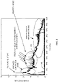
- FIG. 2 is a plot of an example noise spectrum of an example fan of an example electronic device.
- one or both of the fans 102 of the electronic device 100 FIG. 1 may produce the acoustic signal shown in the plot of FIG. 2 .
- background noise 202 is shown along the bottom of the plot at or near approximately -10 decibels (dB).
- Typical fan noise is shown with the example acoustic signal 204. This fan noise may be produced, for example, by the fan 102 of the electronic device 100.
- there are high pitch tones appearing in the acoustic signal 204 between about 1000 hertz (Hz) and about 2000 Hz. These high pitch tones are irritating to a human.
- the acoustic signal 204 may have low pitch tones that are irritating a human.
- low pitch tones from about 10Hz to about 200Hz may be irritating to people.
- the low pitch tone may be produced by one or more of the components of the electronic device 100. Though, some examples disclosed herein are discussed in terms of masking a high tone, these examples may be used to flatten the acoustic signal and mask the high pitch tones and/or low pitch tones.
- FIG. 3 is a plot of example power spectral densities as a function of frequency illustrative of different colors of noise.
- Color of noise refers to the power spectrum of the noise signal. Different colors of noise sound different to human ears.
- the examples disclosed herein can be used to recolor or otherwise alter the acoustic signal toward pink noise for better human perception.
- energy is added to the acoustic signal 204 to recolor the acoustic signal 204.
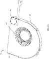
- FIG. 4A is a top, perspective view of the example fan 102 of the electronic device 100 of FIG. 1 showing a position 400 of an example sound transducer 402 (see FIGS. 4D and 4E ).
- the fan 102 includes an example cover or top plate 404 and an example housing 406.
- the fan top plate 404 has a thickness of about 0.5 millimeters (mm).
- the fan 102 also includes fan blade 408.
- the top cover 404 and the housing 406 protect the fan blade 408 from foreign objects such as, for example, dust or minimizes the effect of foreign objects on the fan blade 408.
- the fan blade 408 produces an air flow when rotated to dissipate heat generated by components of the electronic device 100.
- the fan 102 also includes lead wires that connect the fan 102 to other components of the electronic device 100.
- the lead wires are embodied on a flexible printed circuit (PFC) 410.
- the PFC 410 communicatively couples the fan 102 to, for example, processing components such as, for example, one or more of the components of FIG. 6 .
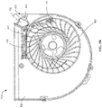
- FIG. 4B is a top view of the fan 102 of FIG. 4A showing two example microphones 412 in the top plate 404.
- the microphones 412 in the top plate 404 of the fan 102 are referred to as fan microphones in this description. However, in the claims, the components may be referred as microphones.
- the fan microphones 412 gather acoustic signals from the fan 102.
- the fan microphones 412 are coupled to microphone boards 414, which are flexible circuit boards that couple the fan microphones 412 to the PFC 410.
- the fan microphones 412 are located in the cutwater feature or region 416 of the fan 102 (see also FIG. 4E ).
- the cutwater region 416 is the tongue feature on the fan 102.
- the cutwater region 416 is used for air compression and is where the fan noise is mainly generated. In some examples, the cutwater region 416 is where the maximum or peak noise is observed.
- the fan microphones 412 also are used to monitor the system component noises inside the chassis of the electronic device 100, such as, for example if the fan noise pattern is abnormal due to dust or rotor failure. In some examples, the fan microphones 412 measure other high frequency noise in the electronic device 100. For example, the fan microphones 412 can listen to the system noises such as, for example, singing capacitors, power supplies, and/or noises or other components that degrade the signal-to-noise ratio of the main microphones 104. Thus, analysis and manipulation of the acoustic signals gathered by the fan microphones 412 facilitate improvement of the quality of the main microphones 104.
- the fan 102 in the example of FIG. 4C includes six fan microphones in the top plate 404.
- the fan microphones 412 are arranged around the fan blade 408.
- one or more of the fan microphones 412 are arranged at a tangent to the fan blade 408.
- Other arrangement and orientations of the fan microphones 412 could be implemented.
- FIG. 4D is a top view of the fan 102 of FIG. 4A with the top plate 404 removed.
- the view of FIG. 4D shows the sound transducer 402.
- the sound transducer 402 is a speaker such as, for example, a dynamic speaker or speaker driver.
- the sound transducer 402 delivers acoustic energy or signals to reshape the fan noise.
- the sound transducer 402 is adjacent to and/or surrounded by an example speaker surround or sponge 418.
- the speaker sponge 418 mitigates or dampens the effect of vibration when the sound transducer 402 operates.
- the fan microphones 412 detect the fan noise, which is analyzed to identify high pitch tones or noise and/or harsh noise.
- the analysis includes application of an algorithm to generate a noise reshaping signal that can be used to blend, spread out or reshape the high pitch noise for better human perception.
- the noise reshaping signal that is used to reshape the fan noise is generated by the sound transducer 402.
- the reshaped fan noise masks the high pitch tones and is more aesthetically pleasing to the user.
- the sound transducer 402 is located in the cutwater region 416 to facilitating directing the noise reshaping signal at the noise source in the cutwater region to control, cancel, and/or reshape the noise at the source.
- FIG. 4E is an exploded view of the fan 102 of FIG. 4A .
- the top plate 404 includes a recess 420 to house the fan microphones 412 and microphone boards 414. In the illustrated example, there is one recess 420 that houses two fan microphones 412. In other examples, there are additional fan microphones included in the recess 420. In other examples, each fan microphone 412 has its own recess 420.
- the fan 102 also includes a bottom plate 422. In some examples, the fan microphones 412 and microphone boards 414 are coupled to or located in the bottom plate 422.
- the fan housing 406 includes a recess 424 for the sound transducer 402.
- the recess 424 is in the cutwater region 416 so that the sound transducer 402 is close to the source of the fan noise or the main source or area of the fan noise.
- the cutwater region 416 of the fan housing 406 is made of non-functional plastic walls.
- placement of the sound transducer 402 in the cutwater region 416 does not require increasing the size of the fan 102.
- the fan 102 may have a 3 - 5 mm width increase.
- the size of the sound transducer 402 is decreased to avoid alteration in the width of the fan 102.
- the sound transducer 402 may be placed external and adjacent the fan 102.
- FIG. 5A is a top, perspective view of the fan 102 of the electronic device 100 of FIG. 1 showing a position 500 of an alternative example sound transducer 502.
- FIG. 5B is a top view of the fan 102 of FIG. 4A with the top plate 404 removed and showing the position of the two example fan microphones 412 relative to the sound transducer 502.
- FIG. 5C is a top view of the fan 102 of FIG. 5A with the top plate 404 removed and showing the alternative sound transducer 502.
- the sound transducer 502 is a balanced armature.
- the balanced armature 502 has a miniaturized size and is easily integrated into the fan 102 without increasing the size of the fan 102.
- the balanced armature 502 is positioned in the cutwater region 416 in the example of FIGS. 5A-E.
- FIG. 5E is an exploded view of the fan 102 of FIG. 5A and shows a recess 504 in the fan housing 406 to hold the balanced armature 502.
- the balanced armature 502 may be located in a different position in the fan 102 or adjacent to and/or external to the fan 102.
- the examples disclosed herein include sound transducers such as, for example, a dynamic speaker and/or a balanced armature. In other examples other sounds transducers may alternatively or additionally be used such a, for example, or other types of sound transducers that are powerful enough for to deduct or reshape noise at the cutwater region.
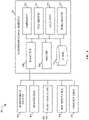
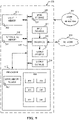
- FIG. 6 is a block diagram of an example system 600 to reshape fan noise of an electronic device in accordance with the teachings of this disclosure.
- the example system 600 may be incorporated into the electronic device 100.
- the example system includes one or more example human presence sensor(s) 602, one or more of the main speaker(s) 106, one or more of the sound transducer(s) 402, 502, one or more of the main microphone(s) 104, one or more of the fan microphone(s) 412, and an example noise reshaping signal generator 604.
- the noise reshaping signal generator 604 includes an example transceiver 606, an example analyzer 608, an example database 610, an example comparator 612, an example tone identifier 614, an example calculator 616, and an example signal adjustor 618.
- the human presence sensor 602 detects if a human is present at the electronic device 100.
- the human presence sensor 602 generates a signal and/or data indicative of a presence or an absence of a human. If a human is not present, the noise reshaping signal generator 604 does not operate to reshape fan noise because there is no human present to be irritated by the fan noise.
- the human presence sensor 602 detects an open or closed position of a lid of the electronic device 100. In such examples, a presence of a human may be assumed based on an open position of the lid.
- the human presence sensor 602 includes a user facing camera that detects whether a person is within a field of view of the camera.
- the human presence sensor 602 includes a camera next to the user facing camera. In some examples, the human presence sensor 602 includes a low-resolution camera. In some examples, the human presence sensor 602 includes a clock to track time. The human presence sensor 602 may indicate that a human is not present after a threshold amount of time that the human presence sensor 602 no longer detects the presence of the human.
- the noise reshaping signal generator 604 receives the signal and/or data from the human presence sensor 602 via the transceiver 606.
- the main speaker 106 also is communicatively coupled to the noise reshaping signal generator 604 via the transceiver 606.
- the analyzer 608 determines if the main speaker 106 is in use. For example, the analyzer 608 determines if the main speaker 106 is outputting audio content to the user. If the main speaker 106 is outputting audio content to the user, the noise reshaping signal generator 604 does not operate to reshape fan noise because the fan noise is obscured or likely obscured by the audio content emanating from the main speaker 106. In this mode of operation, the fan noise is likely not irritating to the user.
- fan microphone 412 gathers acoustic signals that include fan noise from the fan 102 and communicates the signals to the noise reshaping signal generator 604 via the transceiver 606.
- the main microphone 104 also gathers acoustic signals that may include the fan noise.
- the main microphone 104 communicates the signals to the noise reshaping signal generator 604 via the transceiver 606.
- the analyzer 608 determines the workload input of the electronic device 100. For example, the analyzer 608 determines or accesses the central processing unit (CPU) power level. In some examples, the analyzer 608 accesses a basic input/output system (BIOS) table or other data structure that correlates fan noise with pulse width modulation (PWM) measurements. This data or table is generated by pre-calibration for rough noise level versus PWM setting (fan speed setting). This table gives a rough noise level to expect with the electronic device 100.
- An example table includes: PWM setting (duty cycle) Fan Speed (RPM) Estimated Noise Level (dBA) 100% 1500 48 50% 800 42 20% 400 36
- the CPU power level is dynamically based on the workload. A higher power level translates to higher fan speed and more noise. With this information, the analyzer 608 estimates baseline fan noise. The analyzer 608 also determines background or environmental noise based on the signals received from the main microphone 104 and/or fan microphone 412.
- the comparator 612 compares the estimated environmental noise and the baseline fan noise.
- the analyzer 608 determines if there may be system problems or anomalies based on the comparison. In other examples, the analyzer 608 identifies noise signals for reshaping based on the comparison. For example, fan noise that exceeds environmental noise may be candidate noise signals for reshaping.
- the tone identifier 614 identifies high pitch tones in the fan noise.
- Example tones that are high pitched relative to the signal are shown in FIG. 2 .
- the high pitch tones are candidate noise signals for reshaping. Thus, in some examples all fan noise is to be reshaped. In some examples fan noise that exceed environmental noise is to be reshaped. In some examples, high pitch tones are to be reshaped. As disclosed above, these examples may also be applied to low pitch tones.
- the calculator 616 determines a gain to add to the fan noise signal to reshape the signal and blend the noise to mitigate the irritation caused by the noise.
- the signal with the gain determined by the calculator 616 is to be produced by the sound transducer 402, 502.
- this signal is a function of the fast Fourier transform (FFT) of the signals gathered from the fan microphone 412 (and/or the main microphone 104) and the target noise response.
- the target noise response is pink noise or white noise.
- the calculator 616 computes the gain (amplitude) as a product of the original amplitude and a function of the BIOS table data, system power, and FFT of the signals gathered from the fan microphone 412 (and/or the main microphone 104).
- the analyzer 608 identifies critical bands around a high pitch tone.
- the calculator 616 computes the prominence ratio (PR).
- the PR is a parameter that indicates if a tone is prominent. That is, the PR indicates a relative level of a tone compared to surrounding tones. This parameter is used for determining or judging when a tone such as, for example, a mid-frequency tone or a high frequency tone (e.g., great than 1000 Hz) that is emitted by a machine (e.g., the fan 102 of the electronic device 100) could become annoying to the user.
- the PR is determined based on Equation 1.
- PR 10 log B A + C 2 dB where A and C are the critical bands that surround the identified tone, B.
- the prominence ratio is decibel difference of the tone critical band level (B) and the averaged adjacent critical bands (A and C).
- the comparator 612 compares the PR to a threshold level. If the PR exceeds the threshold or does not satisfy the threshold, the identified tone is likely annoying to the user.
- the threshold is 9 dB. Thus, for example, if the band containing the problematic tone (B) has a level 9 dB more than the adjacent bands (A and C), then the tone becomes discomforting the user.
- the analyzer 608 may determine that no reshaping of the fan noise is needed. If the PR is greater than the threshold, the calculator 616 determines a gain for at least one of the critical bands so that the PR would be less than the threshold. In some examples, the analyzer 608 adjusts the gains based on a location of the fan 102 and/or a location of the sound transducer 402, 502. For example, the gain may be adjusted based on a relative position between two or more of the fan 102, the sound transducer 402, 502, and/or the fan microphone 412 (and/or main microphone 104).
- the analyzer 608 considers acceptable noise thresholds.
- An acceptable noise threshold is a level of noise that is acceptable or not irritating to a user.
- the acceptable noise threshold is based on a net gain of the acoustic signal based on the relative locations, operating capabilities, and operating status of one or more of the fan 102, the microphones 104, the speakers 106, the fan microphone 412, the sound transducers 402, 502, and/or other components of the electronic device 102.
- the analyzer 608 can adjust the gain or masking noise or energy based on the acceptable noise threshold.
- the system 600 to reshape fan noise of the electronic device 100 can optimize performance of the electronic device 100 based on noise thresholds that are acceptable to the user. For example, if there is a higher acceptable noise threshold, the electronic device 100 may be able to operate with higher performance.
- the signal adjustor 618 generates a signal or instructions for the gain or masking noise or energy to be produced to reshape the fan noise.
- the noise reshaping signal generator 604 sends a signal or instructions of the gain or masking noise or energy via the transceiver 606 to the sound transducer 402, 502.
- the sound transducer 402, 502 generates an acoustic signal including the gain to reshape the fan noise.
- the main speaker 106 is used in addition to or alternative to the sound transducer 402, 502 to create the acoustic signal that reshapes the noise.
- the noise reshaping signal generator 604 can achieve the fine tuning of different levels by using one set of speakers (e.g., the sound transducers 402, 502 on or near the fan 102) or the other set of speakers (e.g., the main speakers 106 in system chassis), or both sets.
- one set of speakers e.g., the sound transducers 402, 502 on or near the fan 102
- the other set of speakers e.g., the main speakers 106 in system chassis
- the example system 600 uses the fan microphones 412 and/or main microphone 104 and the sounds transducer 402, 502 and/or main speakers 106 to generate purposely shaped audio waveform to blend into the existing fan noise.
- the resulting audio signal is a less annoying noise for better human perception. Because the noise can be reshaped, the examples disclosed herein allow for more fan noise, which allows higher performance of the electronic device 100.
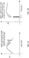
- FIG. 7A is a plot showing example energy added to an example acoustic signal to smooth high tones.
- FIG. 7B is a plot showing example energy added to an example acoustic signal to change a color of noise.
- the energy added by the sound transducer 402, 502 blends or spreads out the high pitch tone.
- FIG. 7A shows fan noise, the high pitch tones (around 1000 Hz) are annoying noise for human perception.
- the system 600 including the main microphones 104 and/or the fan microphones 412 detect the fan noise.
- the analyzer 608 employs the algorithms disclosed herein to identify the high pitch noise of interest, and the calculator 616 determines the signal needed to blend this high pitch signal to flatten it out.
- the sound transducer 402, 502 and/or main speakers 106 output the signal and may include additional frequency signals or to push the color of noise ( FIG. 7B ) toward pink noise for better human perception.
- one predominant frequency that is greater than 1000 Hz in the fan noise spectrum is the blade passing frequency (BPF).
- BPF is a product of the number of blades of the fan and revolutions per sec.
- the examples disclosed herein can track the BPF from the speed of the fan 102 and identify the critical bands A and C, then raise level of the critical bands to an optimal level so that the PR is less than 9 dB.
- the system 600 includes means for processing an acoustic signal.
- the processing means is implemented by any processor structured to perform the corresponding operation by executing software or firmware, or hardware circuit (e.g., discrete and/or integrated analog and/or digital circuitry, an FPGA, a PLD, a FPLD, an ASIC, a comparator, an operational-amplifier (op-amp), a logic circuit, etc.) structured to perform the corresponding operation without executing software or firmware, but other structures are likewise appropriate.
- the noise reshaping signal generator 604 implements the processing means.
- While an example manner of implementing the noise reshaping signal generator 604 is illustrated in FIG. 6 , one or more of the elements, processes and/or devices illustrated in FIG. 6 may be combined, divided, re-arranged, omitted, eliminated and/or implemented in any other way. Further, the example human presence sensor(s) 602, the example transceiver 606, the examiner analyzer 608, the example comparator 612, the example tone identifier 614, the example calculator 616, the example signal adjustor 618, and/or, more generally, the example noise reshaping signal generator 604 of FIG. 6 may be implemented by hardware, software, firmware and/or any combination of hardware, software and/or firmware.
- any of the example human presence sensor(s) 602, the example transceiver 606, the examiner analyzer 608, the example comparator 612, the example tone identifier 614, the example calculator 616, the example signal adjustor 618, and/or, more generally, the example noise reshaping signal generator 604 could be implemented by one or more analog or digital circuit(s), logic circuits, programmable processor(s), programmable controller(s), graphics processing unit(s) (GPU(s)), digital signal processor(s) (DSP(s)), application specific integrated circuit(s) (ASIC(s)), programmable logic device(s) (PLD(s)) and/or field programmable logic device(s) (FPLD(s)).
- At least one of the example human presence sensor(s) 602, the example transceiver 606, the examiner analyzer 608, the example comparator 612, the example tone identifier 614, the example calculator 616, the example signal adjustor 618, and/or the example noise reshaping signal generator 604 is/are hereby expressly defined to include a non-transitory computer readable storage device or storage disk such as a memory, a digital versatile disk (DVD), a compact disk (CD), a Blu-ray disk, etc. including the software and/or firmware. Further still, the example noise reshaping signal generator 604 of FIG.
- the phrase "in communication,” including variations thereof, encompasses direct communication and/or indirect communication through one or more intermediary components, and does not require direct physical (e.g., wired) communication and/or constant communication, but rather additionally includes selective communication at periodic intervals, scheduled intervals, aperiodic intervals, and/or one-time events.
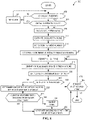
- FIG. 8 A flowchart representative of example hardware logic, machine readable instructions, hardware implemented state machines, and/or any combination thereof for implementing the system 600 of FIG. 6 is shown in FIG. 8 .
- the machine readable instructions may be one or more executable programs or portion(s) of an executable program for execution by a computer processor and/or processor circuitry, such as the processor 912 shown in the example processor platform 900 discussed below in connection with FIG. 9 .
- the program may be embodied in software stored on a non-transitory computer readable storage medium such as a CD-ROM, a floppy disk, a hard drive, a DVD, a Blu-ray disk, or a memory associated with the processor 912, but the entire program and/or parts thereof could alternatively be executed by a device other than the processor 912 and/or embodied in firmware or dedicated hardware.
- a non-transitory computer readable storage medium such as a CD-ROM, a floppy disk, a hard drive, a DVD, a Blu-ray disk, or a memory associated with the processor 912
- the entire program and/or parts thereof could alternatively be executed by a device other than the processor 912 and/or embodied in firmware or dedicated hardware.
- the example program is described with reference to the flowchart illustrated in FIG. 8 , many other methods of implementing the example system 600 and/or the noise reshaping signal generator 604 may alternatively be used. For example, the order of execution of the blocks
- any or all of the blocks may be implemented by one or more hardware circuits (e.g., discrete and/or integrated analog and/or digital circuitry, an FPGA, an ASIC, a comparator, an operational-amplifier (op-amp), a logic circuit, etc.) structured to perform the corresponding operation without executing software or firmware.
- the processor circuitry may be distributed in different network locations and/or local to one or more devices (e.g., a multi-core processor in a single machine, multiple processors distributed across a server rack, etc.).
- the machine readable instructions described herein may be stored in one or more of a compressed format, an encrypted format, a fragmented format, a compiled format, an executable format, a packaged format, etc.
- Machine readable instructions as described herein may be stored as data or a data structure (e.g., portions of instructions, code, representations of code, etc.) that may be utilized to create, manufacture, and/or produce machine executable instructions.
- the machine readable instructions may be fragmented and stored on one or more storage devices and/or computing devices (e.g., servers) located at the same or different locations of a network or collection of networks (e.g., in the cloud, in edge devices, etc.).
- the machine readable instructions may require one or more of installation, modification, adaptation, updating, combining, supplementing, configuring, decryption, decompression, unpacking, distribution, reassignment, compilation, etc. in order to make them directly readable, interpretable, and/or executable by a computing device and/or other machine.
- the machine readable instructions may be stored in multiple parts, which are individually compressed, encrypted, and stored on separate computing devices, wherein the parts when decrypted, decompressed, and combined form a set of executable instructions that implement one or more functions that may together form a program such as that described herein.
- machine readable instructions may be stored in a state in which they may be read by processor circuitry, but require addition of a library (e.g., a dynamic link library (DLL)), a software development kit (SDK), an application programming interface (API), etc. in order to execute the instructions on a particular computing device or other device.
- a library e.g., a dynamic link library (DLL)
- SDK software development kit
- API application programming interface
- the machine readable instructions may need to be configured (e.g., settings stored, data input, network addresses recorded, etc.) before the machine readable instructions and/or the corresponding program(s) can be executed in whole or in part.
- machine readable media may include machine readable instructions and/or program(s) regardless of the particular format or state of the machine readable instructions and/or program(s) when stored or otherwise at rest or in transit.
- the machine readable instructions described herein can be represented by any past, present, or future instruction language, scripting language, programming language, etc.
- the machine readable instructions may be represented using any of the following languages: C, C++, Java, C#, Perl, Python, JavaScript, HyperText Markup Language (HTML), Structured Query Language (SQL), Swift, etc.
- the example processes of FIG. 8 may be implemented using executable instructions (e.g., computer and/or machine readable instructions) stored on a non-transitory computer and/or machine readable medium such as a hard disk drive, a flash memory, a read-only memory, a compact disk, a digital versatile disk, a cache, a random-access memory and/or any other storage device or storage disk in which information is stored for any duration (e.g., for extended time periods, permanently, for brief instances, for temporarily buffering, and/or for caching of the information).
- a non-transitory computer readable medium is expressly defined to include any type of computer readable storage device and/or storage disk and to exclude propagating signals and to exclude transmission media.
- A, B, and/or C refers to any combination or subset of A, B, C such as (1) A alone, (2) B alone, (3) C alone, (4) A with B, (5) A with C, (6) B with C, and (7) A with B and with C.
- the phrase "at least one of A and B" is intended to refer to implementations including any of (1) at least one A, (2) at least one B, and (3) at least one A and at least one B.
- the phrase "at least one of A or B" is intended to refer to implementations including any of (1) at least one A, (2) at least one B, and (3) at least one A and at least one B.
- the phrase "at least one of A and B" is intended to refer to implementations including any of (1) at least one A, (2) at least one B, and (3) at least one A and at least one B.
- the phrase "at least one of A or B" is intended to refer to implementations including any of (1) at least one A, (2) at least one B, and (3) at least one A and at least one B.
- the program 800 of FIG. 8 includes the human presence sensor 602 detecting if a human is present before the electronic device 100 (block 802).
- a human present at the electronic device 100 indicates that the example system 600 of FIG 6 may be implemented to reshape fan noise to enhance the experience of the user by masking irritating fan noise.
- the analyzer 608 determines if a human is present based on data provided to or gathered by the noise reshaping signal generator 604. If a human is not present, the noise reshaping signal generator 604 and the system 600 in general take no action (block 804) with respect to reshaping fan noise.
- the analyzer 608 determines if one or more of the main speakers 106 of the electronic device 100 are in use (block 806). If one or more of the main speakers 106 are in use, the user of the electronic device 100 is likely consuming audio media and the fan noise would be obscured. If the main speakers 106 are in use, the noise reshaping signal generator 604 and the system 600 in general take no action (block 804) with respect to reshaping fan noise.
- the analyzer 608 accesses the workload, operating power level, or CPU power level of the electronic device 100 (block 808).
- the analyzer 608 estimates baseline fan noise (block 810) based on the workload or operating power level of the electronic device 100.
- the fan microphone 412 detects environmental noise (block 812). For example, the fan microphone 412 detects the background noise at the fan 102.
- the main microphone 104 supplements the data gathered from the fan microphone 412. In other examples, the main microphone 104 is used in place of the fan microphone 412.
- the comparator 612 compares the environmental noise to the baseline fan noise (block 814).
- the tone identifier 614 identifies high pitch tones (block 816). In some examples, the tone identifier 614 identifies high pitch tones in the fan noise signal. In some examples, the tone identifier 614 identifies high pitch tones in the comparison of the fan noise with the environmental or background noise.
- the analyzer 608 identifies critical bands around the identified high pitch tone (block 818).
- the calculator 616 calculates the prominence ratio (PR) based on the identified high pitch tone and critical bands (block 820). In some examples, the calculator 616 uses Equation 1 to determine the PR.
- the comparator 612 compares the PR to a threshold (block 822). If the PR is below or otherwise does not meet the threshold, the analyzer 608 may determine that the fan noise signal is not be reshaped.
- the example process 800 continues with the analyzer 608 determining if another high pitch tone is to be identified (block 824). If another high pitch tone is to be identified, the tone identifier identifies another high pitch tone (block 816), and the process 800 proceeds as disclosed above. If the analyzer 608 determines that another tone is not to be identified, the process 800 ends.
- the calculator determines a gain for at least one of the critical bands so that the PR would be less than the threshold (block 826).
- the analyzer 608 determines if the gains are to be adjusted based on a fan location and/or a sound transducer location (block 828). The gains are to be adjusted, the analyzer 608 adjusts the gains based on a location of the fan 102 and/or a location of the sound transducer 402, 502 (block 830).
- the signal adjustor 618 If the analyzer 608 determines that the gains are not to be adjusted (block 828) or after the gains are adjusted (block 830), the signal adjustor 618 generates a signal or instructions for the gain or masking noise or energy to be produced to reshape the fan noise.
- the sound transducer 402, 502 generates the masking noise, which is an acoustic signal including the gain, to reshape the fan noise (block 832).
- the example process 800 continues with the analyzer 608 determining if another high pitch tone is to be identified (block 824). If another high pitch tone is to be identified, the tone identifier identifies another high pitch tone (block 816), and the process 800 proceeds as disclosed above. If the analyzer 608 determines that another tone is not to be identified, the process 800 ends.
- FIG. 9 is a block diagram of an example processor platform 900 structured to execute the instructions of FIG. 8 to implement the system of FIG. 6 .
- the processor platform 900 can be, for example, a server, a personal computer, a workstation, a self-learning machine (e.g., a neural network), a mobile device (e.g., a cell phone, a smart phone, a tablet such as an iPad TM ), a personal digital assistant (PDA), an Internet appliance, a DVD player, a CD player, a digital video recorder, a Blu-ray player, a gaming console, a personal video recorder, a set top box, a headset or other wearable device, or any other type of computing device.
- a self-learning machine e.g., a neural network
- a mobile device e.g., a cell phone, a smart phone, a tablet such as an iPad TM
- PDA personal digital assistant
- an Internet appliance e.g., a DVD player,
- the processor platform 900 of the illustrated example includes a processor 112.
- the processor 912 of the illustrated example is hardware.
- the processor 912 can be implemented by one or more integrated circuits, logic circuits, microprocessors, GPUs, DSPs, or controllers from any desired family or manufacturer.
- the hardware processor may be a semiconductor based (e.g., silicon based) device.
- the processor 912 implements the noise reshaping signal generator 604, the transceiver 606, the analyzer 608, the comparator 612, the tone identifier 614, the calculator 616, and the signal adjustor 618.
- the processor 912 of the illustrated example includes a local memory 913 (e.g., a cache).
- the processor 912 of the illustrated example is in communication with a main memory including a volatile memory 914 and a non-volatile memory 916 via a bus 918.
- the volatile memory 914 may be implemented by Synchronous Dynamic Random Access Memory (SDRAM), Dynamic Random Access Memory (DRAM), RAMBUS ® Dynamic Random Access Memory (RDRAM ® ) and/or any other type of random access memory device.
- the non-volatile memory 916 may be implemented by flash memory and/or any other desired type of memory device. Access to the main memory 914, 916 is controlled by a memory controller.
- the processor platform 900 of the illustrated example also includes an interface circuit 920.
- the interface circuit 920 may be implemented by any type of interface standard, such as an Ethernet interface, a universal serial bus (USB), a Bluetooth ® interface, a near field communication (NFC) interface, and/or a PCI express interface.
- one or more input devices 922 are connected to the interface circuit 920.
- the input device(s) 922 permit(s) a user to enter data and/or commands into the processor 1012.
- the input device(s) can be implemented by, for example, an audio sensor, a microphone, a camera (still or video), a keyboard, a button, a mouse, a touchscreen, a track-pad, a trackball, isopoint and/or a voice recognition system.
- One or more output devices 924 are also connected to the interface circuit 920 of the illustrated example.
- the output devices 1024 can be implemented, for example, by display devices (e.g., a light emitting diode (LED), an organic light emitting diode (OLED), a liquid crystal display (LCD), a cathode ray tube display (CRT), an in-place switching (IPS) display, a touchscreen, etc.), a tactile output device, a printer and/or speaker.
- display devices e.g., a light emitting diode (LED), an organic light emitting diode (OLED), a liquid crystal display (LCD), a cathode ray tube display (CRT), an in-place switching (IPS) display, a touchscreen, etc.
- the interface circuit 920 of the illustrated example thus, typically includes a graphics driver card, a graphics driver chip and/or a graphics driver processor.
- the interface circuit 920 of the illustrated example also includes a communication device such as a transmitter, a receiver, a transceiver, a modem, a residential gateway, a wireless access point, and/or a network interface to facilitate exchange of data with external machines (e.g., computing devices of any kind) via a network 926.
- the communication can be via, for example, an Ethernet connection, a digital subscriber line (DSL) connection, a telephone line connection, a coaxial cable system, a satellite system, a line-of-site wireless system, a cellular telephone system, etc.
- DSL digital subscriber line
- the processor platform 900 of the illustrated example also includes one or more mass storage devices 928 for storing software and/or data.
- mass storage devices 1028 include floppy disk drives, hard drive disks, compact disk drives, Blu-ray disk drives, redundant array of independent disks (RAID) systems, and digital versatile disk (DVD) drives.
- the machine executable instructions 932 of FIG. 8 may be stored in the mass storage device 928, in the volatile memory 914, in the non-volatile memory 916, and/or on a removable non-transitory computer readable storage medium such as a CD or DVD.
- example systems, apparatus, articles of manufacture, and methods have been disclosed that abate, cancel, reduce, reshape or otherwise mask acoustic noise produced by fans in electronic devices. These examples control the noise characteristics of the fans for improved human perception.
- the example fan hardware designs disclosed herein cancel the noise at the fan source.
- the examples disclosed herein enable the noise to be reshaped and abated without using thicker designs with larger blower. These examples disclosed herein also do not require a redesign of the cooling fans themselves.
- the examples disclosed herein also do not cap workload or power level performance of the electronic device 100. Because the fan noise is controlled, the examples disclosed herein enable electronic devices to operate at a higher power with increased fan operation and noise without causing discomfort to the human users.
- the control of the noise characteristics using the examples disclosed herein improve operation of computing devices by enabling higher system performance with improved thermal control.
- fan performance is limited by its noise, for example a fan could deliver up to 10 cubic feet per minute (CFM) open air flowrate, but the noise level at this fan speed could reach 50 dB, which is much higher than most of the original equipment manufacturer specifications (which range from about 40 dB to about 45 dB).
- the fan noise can be reduced by several decibels, which is enough for the fan to perform and operate unrestrained. These examples also increase the system on chip power and system performance. Reducing the noise by several decibels at its maximum fan speed is beneficial for customers because the electronic device can be made more powerful or thinner and lighter without seekingng to system noise.
- Example 1 includes a system to reshape fan noise of a fan of an electronic device.
- the system includes a microphone to detect a first acoustic signal including fan noise.
- the system also includes a processor to: identify a tone in the first acoustic signal; and determine a gain to add to the first acoustic signal to mask the tone.
- the system also includes a sound transducer to present a second acoustic signal including the gain.
- Example 2 includes the system of Example 1, and optionally includes the microphone being coupled to a housing of the fan in an interior of the electronic device.
- Example 3 includes the system of any of Examples 1-2, and optionally includes the microphone being positioned at or near a cutwater region of the fan.
- Example 4 includes the system of any of Examples 1-3, and optionally includes the microphone being a first microphone and the system including a second microphone to detect the first acoustic signal.
- Example 5 includes the system of any of Examples 1-4, and optionally includes the sound transducer being coupled to a housing of the fan in an interior of the electronic device.
- Example 6 includes the system of any of Examples 1-5, and optionally includes the sound transducer being a dynamic speaker.
- Example 7 includes the system of any of Examples 1-6, and optionally includes the sound transducer being a balanced armature.
- Example 8 includes the system of any of Examples 1-7, and optionally includes the processor is to: identify a critical band adjacent the tone; calculate a prominence ratio for the tone; and determine the gain based on the prominence ratio.
- Example 9 includes the system of any of Examples 1-8, and optionally includes the processor is to: identify a first critical band adjacent the tone; identify a second critical band adjacent the tone; calculate a prominence ratio for the tone based on the first critical band and the second critical band; compare the prominence ratio to a threshold; and determine the gain to add when the prominence ratio does not satisfy the threshold, the gain including a first gain for the second acoustic signal in the first critical band and a second gain for the second acoustic signal in the second critical band.
- Example 10 includes the system of any of Examples 1-9, and optionally includes the gain being adjusted based on a location of at least one of the fan, the microphone, or the sound transducer.
- Example 11 includes the system of any of Examples 1-10, and optionally includes the gain being adjusted based on a relative positioning among the fan, the microphone, and the sound transducer.
- Example 12 includes the system of any of Examples 1-11, and optionally includes the gain being adjusted to change a color of the noise.
- Example 13 includes the system of any of Examples 1-12, and optionally includes the processor is to: access data indicative of a presence of a human near the electronic device; and identify the tone based on the presence.
- Example 14 includes the system of any of Examples 1-13, and optionally includes the processor is to: access data indicative of when a speaker of the electronic device is in use, the speaker positioned to provide audio content to a user of the electronic device; and identify the tone based when the speaker is not in use.
- Example 15 includes a system to reshape fan noise of a fan of an electronic device.
- the system includes means for detecting a first acoustic signal including fan noise.
- the system includes means for processing the acoustic signal, the processing means to: identify a tone in the acoustic signal; and determine a gain to add to the acoustic signal to mask the tone.
- the system also includes means for generating a second acoustic signal including the gain.
- Example 16 includes the system of Example 15, and optionally includes the detecting means being coupled to a housing of the fan in an interior of the electronic device.
- Example 17 includes the system of any of Examples 15-16, and optionally includes the detecting means being positioned at or near a cutwater region of the fan.
- Example 18 includes the system of any of Examples 15-17, and optionally includes the detecting means including two microphones to detect the first acoustic signal.
- Example 19 includes the system of any of Examples 15-18, and optionally includes the generating means being coupled to a housing of the fan in an interior of the electronic device.
- Example 20 includes the system of any of Examples 15-19, and optionally includes the generating means including a dynamic speaker.
- Example 21 includes the system of any of Examples 15-20, and optionally includes the generating means including a balanced armature.
- Example 22 includes the system of any of Examples 15-21, and optionally includes the processing means is to: identify a critical band adjacent the tone; calculate a prominence ratio for the tone; and determine the gain based on the prominence ratio.
- Example 23 includes the system of any of Examples 15-22, and optionally includes the processing means is to: identify a first critical band adjacent the tone; identify a second critical band adjacent the tone; calculate a prominence ratio for the tone based on the first critical band and the second critical band; compare the prominence ratio to a threshold; and determine the gain to add when the prominence ratio does not satisfy the threshold, the gain including a first gain for the second acoustic signal in the first critical band and a second gain for the second acoustic signal in the second critical band.
- Example 24 includes the system of any of Examples 15-23, and optionally includes the gain being adjusted based on a location of at least one of the fan, the detecting means, or the generating means.
- Example 25 includes the system of any of Examples 15-24, and optionally includes the gain being adjusted based on a relative positioning among the fan, the detecting means, and the generating means.
- Example 26 includes the system of any of Examples 15-25, and optionally includes the gain being adjusted to change a color of the noise.
- Example 27 includes the system of any of Examples 15-26, and optionally includes the processing means is to: access data indicative of a presence of a human near the electronic device; and identify the tone based on the presence.
- Example 28 includes the system of any of Examples 15-27, and optionally includes the processing means is to: access data indicative of when a speaker of the electronic device is in use, the speaker positioned to provide audio content to a user of the electronic device; and identify the tone based when the speaker is not in use.
- Example 29 includes an apparatus to reshape fan noise of a fan of an electronic device.
- the apparatus includes a memory and processor circuitry to execute instructions to: identify a tone in a detected first acoustic signal; determine a gain to add to the first acoustic signal to mask the tone; and cause a sound transducer to generate a second acoustic signal including the gain.
- Example 30 includes the apparatus of Example 29, and optionally includes the processor circuitry to: identify a critical band adjacent the tone; calculate a prominence ratio for the tone; and determine the gain based on the prominence ratio.
- Example 31 includes the apparatus of any of Examples 29-30, and optionally includes the processor circuitry to: identify a first critical band adjacent the tone; identify a second critical band adjacent the tone; calculate a prominence ratio for the tone based on the first critical band and the second critical band; compare the prominence ratio to a threshold; and determine the gain to add when the prominence ratio does not satisfy the threshold, the gain including a first gain for the second acoustic signal in the first critical band and a second gain for the second acoustic signal in the second critical band.
- Example 32 includes the apparatus of any of Examples 29-31, and optionally includes the processor circuitry to adjust the gain based on a location of at least one of the fan, a microphone that detects the first acoustic signal, or the sound transducer.
- Example 33 includes the apparatus of any of Examples 29-32, and optionally includes the processor circuitry to adjust the gain based on a relative positioning among the fan, a microphone that detects the first acoustic signal, and the sound transducer.
- Example 34 includes the apparatus of any of Examples 29-33, and optionally includes the processor circuitry to adjust the gain to change a color of the noise.
- Example 35 includes the apparatus of any of Examples 29-34, and optionally includes the processor circuitry to: access data indicative of a presence of a human near the electronic device; and identify the tone based on the presence.
- Example 36 includes the apparatus of any of Examples 29-35, and optionally includes the processor circuitry to: access data indicative of when a speaker of the electronic device is in use, the speaker positioned to provide audio content to a user of the electronic device; and identify the tone based when the speaker is not in use.
- Example 37 includes a non-transitory computer readable storage medium comprising instructions which, when executed, cause one or more processors to at least: identify a tone in a detected first acoustic signal; determine a gain to add to the first acoustic signal to mask the tone; and cause a sound transducer to generate a second acoustic signal including the gain.
- Example 38 includes the medium of Example 37, and optionally includes the instructions causing the one or more processors to: identify a critical band adjacent the tone; calculate a prominence ratio for the tone; and determine the gain based on the prominence ratio.
- Example 39 includes the medium of any of Examples 37-38, and optionally includes the instructions causing the one or processors to identify a first critical band adjacent the tone; identify a second critical band adjacent the tone; calculate a prominence ratio for the tone based on the first critical band and the second critical band; compare the prominence ratio to a threshold; and determine the gain to add when the prominence ratio does not satisfy the threshold, the gain including a first gain for the second acoustic signal in the first critical band and a second gain for the second acoustic signal in the second critical band.
- Example 40 includes the medium of any of Examples 37-39, and optionally includes the instructions causing the one or more processors to adjust the gain based on a location of at least one of the fan, a microphone that detects the first acoustic signal, or the sound transducer.
- Example 41 includes the medium of any of Examples 37-40, and optionally includes the instructions causing the one or more processors to adjust the gain based on a relative positioning among the fan, a microphone that detects the first acoustic signal, and the sound transducer.
- Example 42 includes the medium of any of Examples 37-41, and optionally includes the instructions causing the one or more processors to adjust the gain to change a color of the noise.
- Example 43 includes the medium of any of Examples 37-42, and optionally includes the instructions causing the one or more processors to: access data indicative of a presence of a human near the electronic device; and identify the tone based on the presence.
- Example 44 includes the medium of any of Examples 37-43, and optionally includes the instructions causing the one or more processors to: access data indicative of when a speaker of the electronic device is in use, the speaker positioned to provide audio content to a user of the electronic device; and identify the tone based when the speaker is not in use.
- Example 45 includes a method of reshaping fan noise of a fan of an electronic device.
- the method includes identifying, by executing instructions with a processor, a tone in a first acoustic signal, the first acoustic signal including fan noise; determining, by executing an instruction with the processor, a gain to add to the first acoustic signal to mask the tone; and generating a second acoustic signal including the gain.
- Example 46 include the method of Example 45, and optionally includes identifying, by executing an instruction with the processor, a critical band adjacent the tone; calculating, by executing an instruction with the processor, a prominence ratio for the tone; and determining, by executing an instruction with the processor, the gain based on the prominence ratio.
- Example 47 includes the method of any of Examples 45-46, and optionally includes identifying, by executing an instruction with the processor, a first critical band adjacent the tone; identifying, by executing an instruction with the processor, a second critical band adjacent the tone; calculating, by executing an instruction with the processor, a prominence ratio for the tone based on the first critical band and the second critical band; comparing, by executing an instruction with the processor, the prominence ratio to a threshold; and determining, by executing an instruction with the processor, the gain to add when the prominence ratio does not satisfy the threshold, the gain including a first gain for the second acoustic signal in the first critical band and a second gain for the second acoustic signal in the second critical band.
- Example 48 includes the method of any of Examples 45-47, and optionally includes adjusting, by executing an instruction with the processor, the gain based on a location of at least one of the fan, a microphone that detects the first acoustic signal, or the sound transducer.
- Example 49 includes the method of any of Examples 45-48, and optionally includes adjusting, by executing an instruction with the processor, the gain based on a relative positioning among the fan, a microphone that detects the first acoustic signal, and the sound transducer.
- Example 50 includes the method of any of Examples 45-49, and optionally includes adjusting, by executing an instruction with the processor, the gain to change a color of the noise.
- Example 51 includes the method of any of Examples 45-50, and optionally includes accessing data indicative of a presence of a human near the electronic device; and identifying, by executing an instruction with the processor, the tone based on the presence.
- Example 52 includes the method of any of Examples 45-51, and optionally includes accessing data indicative of when a speaker of the electronic device is in use, the speaker positioned to provide audio content to a user of the electronic device; and identifying, by executing an instruction with the processor, the tone based when the speaker is not in use.
- the tone is a high pitch tone. In some of Examples 1-52, the tone is a low pitch tone. In some of Examples 1-52, the tone is a combination of a tones including high pitches and/or low pitches.
Landscapes
- Engineering & Computer Science (AREA)
- Physics & Mathematics (AREA)
- Acoustics & Sound (AREA)
- Signal Processing (AREA)
- Multimedia (AREA)
- Health & Medical Sciences (AREA)
- Otolaryngology (AREA)
- Theoretical Computer Science (AREA)
- Microelectronics & Electronic Packaging (AREA)
- Thermal Sciences (AREA)
- Computer Hardware Design (AREA)
- Human Computer Interaction (AREA)
- General Engineering & Computer Science (AREA)
- General Physics & Mathematics (AREA)
- Soundproofing, Sound Blocking, And Sound Damping (AREA)
- Structures Of Non-Positive Displacement Pumps (AREA)
- Control Of Positive-Displacement Air Blowers (AREA)
Abstract
Description
- This disclosure relates generally to noise abatement, and, more particularly, to systems and methods to reshape fan noise in electronic devices.
- Some electronic devices reduce the noise level created by fans by using a thicker fan design with a larger, quieter blower. Also, some electronic devices reduce the noise level created by fans by capping performance of the electronic device to require lower cooling needs.
-
-
FIG. 1 is a schematic illustration of an example electronic device. -
FIG. 2 is a plot of an example noise spectrum of an example fan of an example electronic device. -
FIG. 3 is a plot of example power spectral densities as a function of frequency illustrative of different colors of noise. -
FIG. 4A is a top, perspective view of an example fan of the electronic device ofFIG. 1 showing a position of an example sound transducer. -
FIG. 4B is a top view of the fan ofFIG. 4A showing two example microphones in the example fan housing. -
FIG. 4C is a top view of the fan ofFIG. 4A showing six example microphones in the fan housing. -
FIG. 4D is a top view of the fan ofFIG. 4A with a top plate removed and showing an example sound transducer. -
FIG. 4E is an exploded view of the fan ofFIG. 4A . -
FIG. 5A is a top, perspective view of an example fan of the electronic device ofFIG. 1 showing a position of an alternative example sound transducer. -
FIG. 5B is a top view of the fan ofFIG. 4A with a top plate removed and showing a position of two example microphones. -
FIG. 5C is a top view of the fan ofFIG. 5A with the top plate removed and showing an alternative example sound transducer. -
FIG. 5D is an exploded view of the fan ofFIG. 5A . -
FIG. 6 is a block diagram of an example system to reshape fan noise of an electronic device in accordance with the teachings of this disclosure. -
FIG. 7A is a plot showing example energy added to an example acoustic signal to smooth high tones. -
FIG. 7B is a plot showing example energy added to an example acoustic signal to change a color of noise. -
FIG. 8 is a flowchart representative of machine readable instructions which may be executed to implement the example noise reshaping generator and system ofFIG. 6 . -
FIG. 9 is a block diagram of an example processing platform structured to execute the instructions ofFIG. 8 to implement the example noise reshaping generator and system ofFIG. 6 . - The figures are not to scale. Instead, the thickness of the layers or regions may be enlarged in the drawings. Although the figures show layers and regions with clean lines and boundaries, some or all of these lines and/or boundaries may be idealized. In reality, the boundaries and/or lines may be unobservable, blended, and/or irregular. In general, the same reference numbers will be used throughout the drawing(s) and accompanying written description to refer to the same or like parts. As used herein, unless otherwise stated, the term "above" describes the relationship of two parts relative to Earth. A first part is above a second part, if the second part has at least one part between Earth and the first part. Likewise, as used herein, a first part is "below" a second part when the first part is closer to the Earth than the second part. As noted above, a first part can be above or below a second part with one or more of: other parts therebetween, without other parts therebetween, with the first and second parts touching, or without the first and second parts being in direct contact with one another. As used in this patent, stating that any part (e.g., a layer, film, area, region, or plate) is in any way on (e.g., positioned on, located on, disposed on, or formed on, etc.) another part, indicates that the referenced part is either in contact with the other part, or that the referenced part is above the other part with one or more intermediate part(s) located therebetween. As used herein, connection references (e.g., attached, coupled, connected, and joined) may include intermediate members between the elements referenced by the connection reference and/or relative movement between those elements unless otherwise indicated. As such, connection references do not necessarily infer that two elements are directly connected and/or in fixed relation to each other. As used herein, stating that any part is in "contact" with another part is defined to mean that there is no intermediate part between the two parts.
- Unless specifically stated otherwise, descriptors such as "first," "second," "third," etc. are used herein without imputing or otherwise indicating any meaning of priority, physical order, arrangement in a list, and/or ordering in any way, but are merely used as labels and/or arbitrary names to distinguish elements for ease of understanding the disclosed examples. In some examples, the descriptor "first" may be used to refer to an element in the detailed description, while the same element may be referred to in a claim with a different descriptor such as "second" or "third." In such instances, it should be understood that such descriptors are used merely for identifying those elements distinctly that might, for example, otherwise share a same name. As used herein, "approximately" and "about" refer to dimensions that may not be exact due to manufacturing tolerances and/or other real world imperfections. As used herein "substantially real time" refers to occurrence in a near instantaneous manner recognizing there may be real world delays for computing time, transmission, etc. Thus, unless otherwise specified, "substantially real time" refers to real time +/-1 second.
- Electronic devices such as, for example, laptops or notebooks use fans or blowers for cooling, which allow the systems to run at higher power and achieve increased performance. However, the fans create acoustic noise. Users of the electronic devices often find acoustic fan noise very irritating, particularly when the electronic device is running heavy workloads that cause increased operation of the fans.
- Aspects of acoustic noise that are problematic or irritating include the level (or volume) of the noise and the harshness (or quality) of the noise. In addition, human perception of noise also varies based on the profile of the color of the noise.
- The examples disclosed herein modify acoustic noise produced by fans in electronic devices. In the context of this patent modifying noise includes abating, blending, cancelling, flattening, controlling, reducing, smoothing, spreading out, deducting, masking, reshaping, recoloring, or otherwise changing noise produced by fans in electronic devices. These terms may be used interchangeably throughout. These examples control the noise characteristics of the fans for improved human perception. Because the fan noise is controlled, the examples disclosed herein enable electronic devices to operate at a higher power with increased fan operation and noise without causing discomfort to the human users. Thus, the control of the noise characteristics further enable higher system performance.
-
FIG. 1 is a schematic illustration of an example electronic device 100. The electronic device 100 ofFIG. 1 is a laptop or notebook computer. In other examples, the electronic device 100 may be any type of electronic device that includes a fan or blower or other type of device or component that produces noise. The electronic device 100 of the illustrated example includes twofans 102.FIG. 1 shows the position of thefans 102 within the interior of the electronic device 100. Though twofans 102 are shown, in other examples, there may be a different number of fans including, for example, one, three, etc. In addition, the positions of thefans 102 may be in any position in the electronic device 100. - The electronic device 100 also includes
example microphones 104. Themicrophones 104 are the standard, system, or main microphones. Thesemain microphones 104 are used, for example, to detect acoustic signals from a user speaking. Though twomain microphones 104 are shown in the illustrated example ofFIG. 1 , in other examples, there may be a different number of main microphones including, for example, one, three, etc. In addition, the positions of themain microphones 104 may be in any position in the electronic device 100. - The electronic device 100 also includes
example speakers 106. Thespeakers 106 are the standard, system, chassis, or main speakers. Thesemain speakers 106 are used, for example, to present, deliver or otherwise output acoustic signals from the electronic device 100 including, for example, acoustic media for consumption by the user. Though twomain speakers 106 are shown in the illustrated example ofFIG. 1 , in other examples, there may be a different number of main speakers including, for example, one, three, etc. In addition, the positions of themain speakers 106 may be in any position in the electronic device 100. -
FIG. 2 is a plot of an example noise spectrum of an example fan of an example electronic device. For example, one or both of thefans 102 of the electronic device 100FIG. 1 may produce the acoustic signal shown in the plot ofFIG. 2 . In the plot ofFIG. 2 ,background noise 202 is shown along the bottom of the plot at or near approximately -10 decibels (dB). Typical fan noise is shown with the exampleacoustic signal 204. This fan noise may be produced, for example, by thefan 102 of the electronic device 100. In this example, there are high pitch tones appearing in theacoustic signal 204 between about 1000 hertz (Hz) and about 2000 Hz. These high pitch tones are irritating to a human. In other examples, theacoustic signal 204 may have low pitch tones that are irritating a human. For example, low pitch tones from about 10Hz to about 200Hz may be irritating to people. The low pitch tone may be produced by one or more of the components of the electronic device 100. Though, some examples disclosed herein are discussed in terms of masking a high tone, these examples may be used to flatten the acoustic signal and mask the high pitch tones and/or low pitch tones. -
FIG. 3 is a plot of example power spectral densities as a function of frequency illustrative of different colors of noise. Color of noise refers to the power spectrum of the noise signal. Different colors of noise sound different to human ears. The examples disclosed herein can be used to recolor or otherwise alter the acoustic signal toward pink noise for better human perception. In some examples, as disclosed herein, energy is added to theacoustic signal 204 to recolor theacoustic signal 204. -
FIG. 4A is a top, perspective view of theexample fan 102 of the electronic device 100 ofFIG. 1 showing aposition 400 of an example sound transducer 402 (seeFIGS. 4D and4E ). Thefan 102 includes an example cover ortop plate 404 and anexample housing 406. In some examples, thefan top plate 404 has a thickness of about 0.5 millimeters (mm). Thefan 102 also includesfan blade 408. Thetop cover 404 and thehousing 406 protect thefan blade 408 from foreign objects such as, for example, dust or minimizes the effect of foreign objects on thefan blade 408. Thefan blade 408 produces an air flow when rotated to dissipate heat generated by components of the electronic device 100. - The
fan 102 also includes lead wires that connect thefan 102 to other components of the electronic device 100. In the illustrated example ofFIG. 4A , the lead wires are embodied on a flexible printed circuit (PFC) 410. ThePFC 410 communicatively couples thefan 102 to, for example, processing components such as, for example, one or more of the components ofFIG. 6 . -
FIG. 4B is a top view of thefan 102 ofFIG. 4A showing twoexample microphones 412 in thetop plate 404. To distinguish themain microphones 104, themicrophones 412 in thetop plate 404 of thefan 102 are referred to as fan microphones in this description. However, in the claims, the components may be referred as microphones. Thefan microphones 412 gather acoustic signals from thefan 102. In some examples, thefan microphones 412 are coupled tomicrophone boards 414, which are flexible circuit boards that couple thefan microphones 412 to thePFC 410. In the illustrated example, thefan microphones 412 are located in the cutwater feature orregion 416 of the fan 102 (see alsoFIG. 4E ). Thecutwater region 416 is the tongue feature on thefan 102. Thecutwater region 416 is used for air compression and is where the fan noise is mainly generated. In some examples, thecutwater region 416 is where the maximum or peak noise is observed. In some examples, thefan microphones 412 also are used to monitor the system component noises inside the chassis of the electronic device 100, such as, for example if the fan noise pattern is abnormal due to dust or rotor failure. In some examples, thefan microphones 412 measure other high frequency noise in the electronic device 100. For example, thefan microphones 412 can listen to the system noises such as, for example, singing capacitors, power supplies, and/or noises or other components that degrade the signal-to-noise ratio of themain microphones 104. Thus, analysis and manipulation of the acoustic signals gathered by thefan microphones 412 facilitate improvement of the quality of themain microphones 104. - Though two
fan microphones 412 are shown in the example ofFIG. 4B , in other examples other numbers offan microphones 412 may be used such as, for example, one, three, four, etc. In other examples, there could be more. For example, thefan 102 in the example ofFIG. 4C includes six fan microphones in thetop plate 404. In the example ofFIG. 4C , thefan microphones 412 are arranged around thefan blade 408. In some examples, one or more of thefan microphones 412 are arranged at a tangent to thefan blade 408. Other arrangement and orientations of thefan microphones 412 could be implemented. -
FIG. 4D is a top view of thefan 102 ofFIG. 4A with thetop plate 404 removed. The view ofFIG. 4D shows thesound transducer 402. In the illustrated example, thesound transducer 402 is a speaker such as, for example, a dynamic speaker or speaker driver. Thesound transducer 402 delivers acoustic energy or signals to reshape the fan noise. In some examples, thesound transducer 402 is adjacent to and/or surrounded by an example speaker surround orsponge 418. Thespeaker sponge 418 mitigates or dampens the effect of vibration when thesound transducer 402 operates. - As disclosed below, the
fan microphones 412 detect the fan noise, which is analyzed to identify high pitch tones or noise and/or harsh noise. The analysis includes application of an algorithm to generate a noise reshaping signal that can be used to blend, spread out or reshape the high pitch noise for better human perception. The noise reshaping signal that is used to reshape the fan noise is generated by thesound transducer 402. The reshaped fan noise masks the high pitch tones and is more aesthetically pleasing to the user. In the illustrated example, thesound transducer 402 is located in thecutwater region 416 to facilitating directing the noise reshaping signal at the noise source in the cutwater region to control, cancel, and/or reshape the noise at the source. -
FIG. 4E is an exploded view of thefan 102 ofFIG. 4A . Thetop plate 404 includes arecess 420 to house thefan microphones 412 andmicrophone boards 414. In the illustrated example, there is onerecess 420 that houses twofan microphones 412. In other examples, there are additional fan microphones included in therecess 420. In other examples, eachfan microphone 412 has itsown recess 420. Thefan 102 also includes abottom plate 422. In some examples, thefan microphones 412 andmicrophone boards 414 are coupled to or located in thebottom plate 422. - The
fan housing 406 includes arecess 424 for thesound transducer 402. In this example, therecess 424 is in thecutwater region 416 so that thesound transducer 402 is close to the source of the fan noise or the main source or area of the fan noise. In addition, in the illustrated example, thecutwater region 416 of thefan housing 406 is made of non-functional plastic walls. In some examples, placement of thesound transducer 402 in thecutwater region 416 does not require increasing the size of thefan 102. In some examples, thefan 102 may have a 3 - 5 mm width increase. In other examples, the size of thesound transducer 402 is decreased to avoid alteration in the width of thefan 102. Also, in some examples, thesound transducer 402 may be placed external and adjacent thefan 102. -
FIG. 5A is a top, perspective view of thefan 102 of the electronic device 100 ofFIG. 1 showing aposition 500 of an alternativeexample sound transducer 502.FIG. 5B is a top view of thefan 102 ofFIG. 4A with thetop plate 404 removed and showing the position of the twoexample fan microphones 412 relative to thesound transducer 502.FIG. 5C is a top view of thefan 102 ofFIG. 5A with thetop plate 404 removed and showing thealternative sound transducer 502. In this example, thesound transducer 502 is a balanced armature. Thebalanced armature 502 has a miniaturized size and is easily integrated into thefan 102 without increasing the size of thefan 102. - The
balanced armature 502 is positioned in thecutwater region 416 in the example ofFIGS. 5A-E. FIG. 5E is an exploded view of thefan 102 ofFIG. 5A and shows arecess 504 in thefan housing 406 to hold thebalanced armature 502. In other examples, thebalanced armature 502 may be located in a different position in thefan 102 or adjacent to and/or external to thefan 102. The examples disclosed herein include sound transducers such as, for example, a dynamic speaker and/or a balanced armature. In other examples other sounds transducers may alternatively or additionally be used such a, for example, or other types of sound transducers that are powerful enough for to deduct or reshape noise at the cutwater region. -
FIG. 6 is a block diagram of anexample system 600 to reshape fan noise of an electronic device in accordance with the teachings of this disclosure. Theexample system 600 may be incorporated into the electronic device 100. The example system includes one or more example human presence sensor(s) 602, one or more of the main speaker(s) 106, one or more of the sound transducer(s) 402, 502, one or more of the main microphone(s) 104, one or more of the fan microphone(s) 412, and an example noise reshapingsignal generator 604. The noise reshapingsignal generator 604 includes anexample transceiver 606, anexample analyzer 608, anexample database 610, anexample comparator 612, anexample tone identifier 614, anexample calculator 616, and anexample signal adjustor 618. - The
human presence sensor 602 detects if a human is present at the electronic device 100. Thehuman presence sensor 602 generates a signal and/or data indicative of a presence or an absence of a human. If a human is not present, the noise reshapingsignal generator 604 does not operate to reshape fan noise because there is no human present to be irritated by the fan noise. In some examples, thehuman presence sensor 602 detects an open or closed position of a lid of the electronic device 100. In such examples, a presence of a human may be assumed based on an open position of the lid. In some examples, thehuman presence sensor 602 includes a user facing camera that detects whether a person is within a field of view of the camera. In some examples, thehuman presence sensor 602 includes a camera next to the user facing camera. In some examples, thehuman presence sensor 602 includes a low-resolution camera. In some examples, thehuman presence sensor 602 includes a clock to track time. Thehuman presence sensor 602 may indicate that a human is not present after a threshold amount of time that thehuman presence sensor 602 no longer detects the presence of the human. The noise reshapingsignal generator 604 receives the signal and/or data from thehuman presence sensor 602 via thetransceiver 606. - The
main speaker 106 also is communicatively coupled to the noise reshapingsignal generator 604 via thetransceiver 606. Theanalyzer 608 determines if themain speaker 106 is in use. For example, theanalyzer 608 determines if themain speaker 106 is outputting audio content to the user. If themain speaker 106 is outputting audio content to the user, the noise reshapingsignal generator 604 does not operate to reshape fan noise because the fan noise is obscured or likely obscured by the audio content emanating from themain speaker 106. In this mode of operation, the fan noise is likely not irritating to the user. - When the noise reshaping
signal generator 604 operates to reshape fan noise,fan microphone 412 gathers acoustic signals that include fan noise from thefan 102 and communicates the signals to the noise reshapingsignal generator 604 via thetransceiver 606. In some examples, themain microphone 104 also gathers acoustic signals that may include the fan noise. In such examples, themain microphone 104 communicates the signals to the noise reshapingsignal generator 604 via thetransceiver 606. - For the noise reshaping operation, the
analyzer 608 determines the workload input of the electronic device 100. For example, theanalyzer 608 determines or accesses the central processing unit (CPU) power level. In some examples, theanalyzer 608 accesses a basic input/output system (BIOS) table or other data structure that correlates fan noise with pulse width modulation (PWM) measurements. This data or table is generated by pre-calibration for rough noise level versus PWM setting (fan speed setting). This table gives a rough noise level to expect with the electronic device 100. An example table includes:PWM setting (duty cycle) Fan Speed (RPM) Estimated Noise Level (dBA) 100% 1500 48 50% 800 42 20% 400 36 - The CPU power level is dynamically based on the workload. A higher power level translates to higher fan speed and more noise. With this information, the
analyzer 608 estimates baseline fan noise. Theanalyzer 608 also determines background or environmental noise based on the signals received from themain microphone 104 and/orfan microphone 412. - The
comparator 612 compares the estimated environmental noise and the baseline fan noise. Theanalyzer 608 determines if there may be system problems or anomalies based on the comparison. In other examples, theanalyzer 608 identifies noise signals for reshaping based on the comparison. For example, fan noise that exceeds environmental noise may be candidate noise signals for reshaping. - The
tone identifier 614 identifies high pitch tones in the fan noise. Example tones that are high pitched relative to the signal are shown inFIG. 2 . The high pitch tones are candidate noise signals for reshaping. Thus, in some examples all fan noise is to be reshaped. In some examples fan noise that exceed environmental noise is to be reshaped. In some examples, high pitch tones are to be reshaped. As disclosed above, these examples may also be applied to low pitch tones. - The
calculator 616 determines a gain to add to the fan noise signal to reshape the signal and blend the noise to mitigate the irritation caused by the noise. The signal with the gain determined by thecalculator 616 is to be produced by thesound transducer calculator 616 computes the gain (amplitude) as a product of the original amplitude and a function of the BIOS table data, system power, and FFT of the signals gathered from the fan microphone 412 (and/or the main microphone 104). - In some examples, the
analyzer 608 identifies critical bands around a high pitch tone. Thecalculator 616 computes the prominence ratio (PR). The PR is a parameter that indicates if a tone is prominent. That is, the PR indicates a relative level of a tone compared to surrounding tones. This parameter is used for determining or judging when a tone such as, for example, a mid-frequency tone or a high frequency tone (e.g., great than 1000 Hz) that is emitted by a machine (e.g., thefan 102 of the electronic device 100) could become annoying to the user. In some examples, the PR is determined based onEquation 1.
- The
comparator 612 compares the PR to a threshold level. If the PR exceeds the threshold or does not satisfy the threshold, the identified tone is likely annoying to the user. In some examples, the threshold is 9 dB. Thus, for example, if the band containing the problematic tone (B) has a level 9 dB more than the adjacent bands (A and C), then the tone becomes discomforting the user. - If the PR is less than the threshold decibel level, the
analyzer 608 may determine that no reshaping of the fan noise is needed. If the PR is greater than the threshold, thecalculator 616 determines a gain for at least one of the critical bands so that the PR would be less than the threshold. In some examples, theanalyzer 608 adjusts the gains based on a location of thefan 102 and/or a location of thesound transducer fan 102, thesound transducer - In some examples, the
analyzer 608 considers acceptable noise thresholds. An acceptable noise threshold is a level of noise that is acceptable or not irritating to a user. In some examples, the acceptable noise threshold is based on a net gain of the acoustic signal based on the relative locations, operating capabilities, and operating status of one or more of thefan 102, themicrophones 104, thespeakers 106, thefan microphone 412, thesound transducers electronic device 102. Theanalyzer 608 can adjust the gain or masking noise or energy based on the acceptable noise threshold. Thus, in some examples, thesystem 600 to reshape fan noise of the electronic device 100 can optimize performance of the electronic device 100 based on noise thresholds that are acceptable to the user. For example, if there is a higher acceptable noise threshold, the electronic device 100 may be able to operate with higher performance. - The
signal adjustor 618 generates a signal or instructions for the gain or masking noise or energy to be produced to reshape the fan noise. The noise reshapingsignal generator 604 sends a signal or instructions of the gain or masking noise or energy via thetransceiver 606 to thesound transducer sound transducer main speaker 106 is used in addition to or alternative to thesound transducer sound transducer main speaker 106, the noise reshapingsignal generator 604 can achieve the fine tuning of different levels by using one set of speakers (e.g., thesound transducers main speakers 106 in system chassis), or both sets. - Thus, the
example system 600 uses thefan microphones 412 and/ormain microphone 104 and thesounds transducer main speakers 106 to generate purposely shaped audio waveform to blend into the existing fan noise. The resulting audio signal is a less annoying noise for better human perception. Because the noise can be reshaped, the examples disclosed herein allow for more fan noise, which allows higher performance of the electronic device 100. -
FIG. 7A is a plot showing example energy added to an example acoustic signal to smooth high tones.FIG. 7B is a plot showing example energy added to an example acoustic signal to change a color of noise. As shown in these examples, the energy added by thesound transducer FIG. 7A shows fan noise, the high pitch tones (around 1000 Hz) are annoying noise for human perception. In these examples, thesystem 600 including themain microphones 104 and/or thefan microphones 412 detect the fan noise. Theanalyzer 608 employs the algorithms disclosed herein to identify the high pitch noise of interest, and thecalculator 616 determines the signal needed to blend this high pitch signal to flatten it out. Thesound transducer main speakers 106 output the signal and may include additional frequency signals or to push the color of noise (FIG. 7B ) toward pink noise for better human perception. - In some examples, one predominant frequency that is greater than 1000 Hz in the fan noise spectrum is the blade passing frequency (BPF). The BPF is a product of the number of blades of the fan and revolutions per sec. The examples disclosed herein can track the BPF from the speed of the
fan 102 and identify the critical bands A and C, then raise level of the critical bands to an optimal level so that the PR is less than 9 dB. - In the illustrated example of
FIG. 6 , thesystem 600 includes means for processing an acoustic signal. In this example, the processing means is implemented by any processor structured to perform the corresponding operation by executing software or firmware, or hardware circuit (e.g., discrete and/or integrated analog and/or digital circuitry, an FPGA, a PLD, a FPLD, an ASIC, a comparator, an operational-amplifier (op-amp), a logic circuit, etc.) structured to perform the corresponding operation without executing software or firmware, but other structures are likewise appropriate. In some examples, the noise reshapingsignal generator 604 implements the processing means. - While an example manner of implementing the noise reshaping
signal generator 604 is illustrated inFIG. 6 , one or more of the elements, processes and/or devices illustrated inFIG. 6 may be combined, divided, re-arranged, omitted, eliminated and/or implemented in any other way. Further, the example human presence sensor(s) 602, theexample transceiver 606, theexaminer analyzer 608, theexample comparator 612, theexample tone identifier 614, theexample calculator 616, theexample signal adjustor 618, and/or, more generally, the example noise reshapingsignal generator 604 ofFIG. 6 may be implemented by hardware, software, firmware and/or any combination of hardware, software and/or firmware. Thus, for example, any of the example human presence sensor(s) 602, theexample transceiver 606, theexaminer analyzer 608, theexample comparator 612, theexample tone identifier 614, theexample calculator 616, theexample signal adjustor 618, and/or, more generally, the example noise reshapingsignal generator 604 could be implemented by one or more analog or digital circuit(s), logic circuits, programmable processor(s), programmable controller(s), graphics processing unit(s) (GPU(s)), digital signal processor(s) (DSP(s)), application specific integrated circuit(s) (ASIC(s)), programmable logic device(s) (PLD(s)) and/or field programmable logic device(s) (FPLD(s)). When reading any of the apparatus or system claims of this patent to cover a purely software and/or firmware implementation, at least one of the example human presence sensor(s) 602, theexample transceiver 606, theexaminer analyzer 608, theexample comparator 612, theexample tone identifier 614, theexample calculator 616, theexample signal adjustor 618, and/or the example noise reshapingsignal generator 604 is/are hereby expressly defined to include a non-transitory computer readable storage device or storage disk such as a memory, a digital versatile disk (DVD), a compact disk (CD), a Blu-ray disk, etc. including the software and/or firmware. Further still, the example noise reshapingsignal generator 604 ofFIG. 6 may include one or more elements, processes and/or devices in addition to, or instead of, those illustrated inFIG. 6 , and/or may include more than one of any or all of the illustrated elements, processes and devices. As used herein, the phrase "in communication," including variations thereof, encompasses direct communication and/or indirect communication through one or more intermediary components, and does not require direct physical (e.g., wired) communication and/or constant communication, but rather additionally includes selective communication at periodic intervals, scheduled intervals, aperiodic intervals, and/or one-time events. - A flowchart representative of example hardware logic, machine readable instructions, hardware implemented state machines, and/or any combination thereof for implementing the
system 600 ofFIG. 6 is shown inFIG. 8 . The machine readable instructions may be one or more executable programs or portion(s) of an executable program for execution by a computer processor and/or processor circuitry, such as theprocessor 912 shown in theexample processor platform 900 discussed below in connection withFIG. 9 . The program may be embodied in software stored on a non-transitory computer readable storage medium such as a CD-ROM, a floppy disk, a hard drive, a DVD, a Blu-ray disk, or a memory associated with theprocessor 912, but the entire program and/or parts thereof could alternatively be executed by a device other than theprocessor 912 and/or embodied in firmware or dedicated hardware. Further, although the example program is described with reference to the flowchart illustrated inFIG. 8 , many other methods of implementing theexample system 600 and/or the noise reshapingsignal generator 604 may alternatively be used. For example, the order of execution of the blocks may be changed, and/or some of the blocks described may be changed, eliminated, or combined. Additionally or alternatively, any or all of the blocks may be implemented by one or more hardware circuits (e.g., discrete and/or integrated analog and/or digital circuitry, an FPGA, an ASIC, a comparator, an operational-amplifier (op-amp), a logic circuit, etc.) structured to perform the corresponding operation without executing software or firmware. The processor circuitry may be distributed in different network locations and/or local to one or more devices (e.g., a multi-core processor in a single machine, multiple processors distributed across a server rack, etc.). - The machine readable instructions described herein may be stored in one or more of a compressed format, an encrypted format, a fragmented format, a compiled format, an executable format, a packaged format, etc. Machine readable instructions as described herein may be stored as data or a data structure (e.g., portions of instructions, code, representations of code, etc.) that may be utilized to create, manufacture, and/or produce machine executable instructions. For example, the machine readable instructions may be fragmented and stored on one or more storage devices and/or computing devices (e.g., servers) located at the same or different locations of a network or collection of networks (e.g., in the cloud, in edge devices, etc.). The machine readable instructions may require one or more of installation, modification, adaptation, updating, combining, supplementing, configuring, decryption, decompression, unpacking, distribution, reassignment, compilation, etc. in order to make them directly readable, interpretable, and/or executable by a computing device and/or other machine. For example, the machine readable instructions may be stored in multiple parts, which are individually compressed, encrypted, and stored on separate computing devices, wherein the parts when decrypted, decompressed, and combined form a set of executable instructions that implement one or more functions that may together form a program such as that described herein.
- In another example, the machine readable instructions may be stored in a state in which they may be read by processor circuitry, but require addition of a library (e.g., a dynamic link library (DLL)), a software development kit (SDK), an application programming interface (API), etc. in order to execute the instructions on a particular computing device or other device. In another example, the machine readable instructions may need to be configured (e.g., settings stored, data input, network addresses recorded, etc.) before the machine readable instructions and/or the corresponding program(s) can be executed in whole or in part. Thus, machine readable media, as used herein, may include machine readable instructions and/or program(s) regardless of the particular format or state of the machine readable instructions and/or program(s) when stored or otherwise at rest or in transit.
- The machine readable instructions described herein can be represented by any past, present, or future instruction language, scripting language, programming language, etc. For example, the machine readable instructions may be represented using any of the following languages: C, C++, Java, C#, Perl, Python, JavaScript, HyperText Markup Language (HTML), Structured Query Language (SQL), Swift, etc.
- As mentioned above, the example processes of
FIG. 8 may be implemented using executable instructions (e.g., computer and/or machine readable instructions) stored on a non-transitory computer and/or machine readable medium such as a hard disk drive, a flash memory, a read-only memory, a compact disk, a digital versatile disk, a cache, a random-access memory and/or any other storage device or storage disk in which information is stored for any duration (e.g., for extended time periods, permanently, for brief instances, for temporarily buffering, and/or for caching of the information). As used herein, the term non-transitory computer readable medium is expressly defined to include any type of computer readable storage device and/or storage disk and to exclude propagating signals and to exclude transmission media. - "Including" and "comprising" (and all forms and tenses thereof) are used herein to be open ended terms. Thus, whenever a claim employs any form of "include" or "comprise" (e.g., comprises, includes, comprising, including, having, etc.) as a preamble or within a claim recitation of any kind, it is to be understood that additional elements, terms, etc. may be present without falling outside the scope of the corresponding claim or recitation. As used herein, when the phrase "at least" is used as the transition term in, for example, a preamble of a claim, it is open-ended in the same manner as the term "comprising" and "including" are open ended. The term "and/or" when used, for example, in a form such as A, B, and/or C refers to any combination or subset of A, B, C such as (1) A alone, (2) B alone, (3) C alone, (4) A with B, (5) A with C, (6) B with C, and (7) A with B and with C. As used herein in the context of describing structures, components, items, objects and/or things, the phrase "at least one of A and B" is intended to refer to implementations including any of (1) at least one A, (2) at least one B, and (3) at least one A and at least one B. Similarly, as used herein in the context of describing structures, components, items, objects and/or things, the phrase "at least one of A or B" is intended to refer to implementations including any of (1) at least one A, (2) at least one B, and (3) at least one A and at least one B. As used herein in the context of describing the performance or execution of processes, instructions, actions, activities and/or steps, the phrase "at least one of A and B" is intended to refer to implementations including any of (1) at least one A, (2) at least one B, and (3) at least one A and at least one B. Similarly, as used herein in the context of describing the performance or execution of processes, instructions, actions, activities and/or steps, the phrase "at least one of A or B" is intended to refer to implementations including any of (1) at least one A, (2) at least one B, and (3) at least one A and at least one B.
- As used herein, singular references (e.g., "a", "an", "first", "second", etc.) do not exclude a plurality. The term "a" or "an" entity, as used herein, refers to one or more of that entity. The terms "a" (or "an"), "one or more", and "at least one" can be used interchangeably herein. Furthermore, although individually listed, a plurality of means, elements or method actions may be implemented by, e.g., a single unit or processor. Additionally, although individual features may be included in different examples or claims, these may possibly be combined, and the inclusion in different examples or claims does not imply that a combination of features is not feasible and/or advantageous.
- The
program 800 ofFIG. 8 includes thehuman presence sensor 602 detecting if a human is present before the electronic device 100 (block 802). A human present at the electronic device 100 indicates that theexample system 600 ofFIG 6 may be implemented to reshape fan noise to enhance the experience of the user by masking irritating fan noise. In some examples, theanalyzer 608 determines if a human is present based on data provided to or gathered by the noise reshapingsignal generator 604. If a human is not present, the noise reshapingsignal generator 604 and thesystem 600 in general take no action (block 804) with respect to reshaping fan noise. - If a human is present (block 802), the
analyzer 608 determines if one or more of themain speakers 106 of the electronic device 100 are in use (block 806). If one or more of themain speakers 106 are in use, the user of the electronic device 100 is likely consuming audio media and the fan noise would be obscured. If themain speakers 106 are in use, the noise reshapingsignal generator 604 and thesystem 600 in general take no action (block 804) with respect to reshaping fan noise. - If the
main speakers 106 are not in use, theanalyzer 608 accesses the workload, operating power level, or CPU power level of the electronic device 100 (block 808). Theanalyzer 608 estimates baseline fan noise (block 810) based on the workload or operating power level of the electronic device 100. - The
fan microphone 412 detects environmental noise (block 812). For example, thefan microphone 412 detects the background noise at thefan 102. In some examples, themain microphone 104 supplements the data gathered from thefan microphone 412. In other examples, themain microphone 104 is used in place of thefan microphone 412. - The
comparator 612 compares the environmental noise to the baseline fan noise (block 814). Thetone identifier 614 identifies high pitch tones (block 816). In some examples, thetone identifier 614 identifies high pitch tones in the fan noise signal. In some examples, thetone identifier 614 identifies high pitch tones in the comparison of the fan noise with the environmental or background noise. - The
analyzer 608 identifies critical bands around the identified high pitch tone (block 818). Thecalculator 616 calculates the prominence ratio (PR) based on the identified high pitch tone and critical bands (block 820). In some examples, thecalculator 616 usesEquation 1 to determine the PR. - The
comparator 612 compares the PR to a threshold (block 822). If the PR is below or otherwise does not meet the threshold, theanalyzer 608 may determine that the fan noise signal is not be reshaped. Theexample process 800 continues with theanalyzer 608 determining if another high pitch tone is to be identified (block 824). If another high pitch tone is to be identified, the tone identifier identifies another high pitch tone (block 816), and theprocess 800 proceeds as disclosed above. If theanalyzer 608 determines that another tone is not to be identified, theprocess 800 ends. - If the PR is above or otherwise satisfies the threshold (block 822), the calculator determines a gain for at least one of the critical bands so that the PR would be less than the threshold (block 826). In some examples, the
analyzer 608 determines if the gains are to be adjusted based on a fan location and/or a sound transducer location (block 828). The gains are to be adjusted, theanalyzer 608 adjusts the gains based on a location of thefan 102 and/or a location of thesound transducer 402, 502 (block 830). - If the
analyzer 608 determines that the gains are not to be adjusted (block 828) or after the gains are adjusted (block 830), thesignal adjustor 618 generates a signal or instructions for the gain or masking noise or energy to be produced to reshape the fan noise. Thesound transducer - The
example process 800 continues with theanalyzer 608 determining if another high pitch tone is to be identified (block 824). If another high pitch tone is to be identified, the tone identifier identifies another high pitch tone (block 816), and theprocess 800 proceeds as disclosed above. If theanalyzer 608 determines that another tone is not to be identified, theprocess 800 ends. -
FIG. 9 is a block diagram of anexample processor platform 900 structured to execute the instructions ofFIG. 8 to implement the system ofFIG. 6 . Theprocessor platform 900 can be, for example, a server, a personal computer, a workstation, a self-learning machine (e.g., a neural network), a mobile device (e.g., a cell phone, a smart phone, a tablet such as an iPad™), a personal digital assistant (PDA), an Internet appliance, a DVD player, a CD player, a digital video recorder, a Blu-ray player, a gaming console, a personal video recorder, a set top box, a headset or other wearable device, or any other type of computing device. - The
processor platform 900 of the illustrated example includes a processor 112. Theprocessor 912 of the illustrated example is hardware. For example, theprocessor 912 can be implemented by one or more integrated circuits, logic circuits, microprocessors, GPUs, DSPs, or controllers from any desired family or manufacturer. The hardware processor may be a semiconductor based (e.g., silicon based) device. In this example, theprocessor 912 implements the noise reshapingsignal generator 604, thetransceiver 606, theanalyzer 608, thecomparator 612, thetone identifier 614, thecalculator 616, and thesignal adjustor 618. - The
processor 912 of the illustrated example includes a local memory 913 (e.g., a cache). Theprocessor 912 of the illustrated example is in communication with a main memory including avolatile memory 914 and anon-volatile memory 916 via abus 918. Thevolatile memory 914 may be implemented by Synchronous Dynamic Random Access Memory (SDRAM), Dynamic Random Access Memory (DRAM), RAMBUS® Dynamic Random Access Memory (RDRAM®) and/or any other type of random access memory device. Thenon-volatile memory 916 may be implemented by flash memory and/or any other desired type of memory device. Access to themain memory - The
processor platform 900 of the illustrated example also includes aninterface circuit 920. Theinterface circuit 920 may be implemented by any type of interface standard, such as an Ethernet interface, a universal serial bus (USB), a Bluetooth® interface, a near field communication (NFC) interface, and/or a PCI express interface. - In the illustrated example, one or
more input devices 922 are connected to theinterface circuit 920. The input device(s) 922 permit(s) a user to enter data and/or commands into the processor 1012. The input device(s) can be implemented by, for example, an audio sensor, a microphone, a camera (still or video), a keyboard, a button, a mouse, a touchscreen, a track-pad, a trackball, isopoint and/or a voice recognition system. - One or
more output devices 924 are also connected to theinterface circuit 920 of the illustrated example. The output devices 1024 can be implemented, for example, by display devices (e.g., a light emitting diode (LED), an organic light emitting diode (OLED), a liquid crystal display (LCD), a cathode ray tube display (CRT), an in-place switching (IPS) display, a touchscreen, etc.), a tactile output device, a printer and/or speaker. Theinterface circuit 920 of the illustrated example, thus, typically includes a graphics driver card, a graphics driver chip and/or a graphics driver processor. - The
interface circuit 920 of the illustrated example also includes a communication device such as a transmitter, a receiver, a transceiver, a modem, a residential gateway, a wireless access point, and/or a network interface to facilitate exchange of data with external machines (e.g., computing devices of any kind) via anetwork 926. The communication can be via, for example, an Ethernet connection, a digital subscriber line (DSL) connection, a telephone line connection, a coaxial cable system, a satellite system, a line-of-site wireless system, a cellular telephone system, etc. - The
processor platform 900 of the illustrated example also includes one or moremass storage devices 928 for storing software and/or data. Examples of such mass storage devices 1028 include floppy disk drives, hard drive disks, compact disk drives, Blu-ray disk drives, redundant array of independent disks (RAID) systems, and digital versatile disk (DVD) drives. - The machine
executable instructions 932 ofFIG. 8 may be stored in themass storage device 928, in thevolatile memory 914, in thenon-volatile memory 916, and/or on a removable non-transitory computer readable storage medium such as a CD or DVD. - From the foregoing, it will be appreciated that example systems, apparatus, articles of manufacture, and methods have been disclosed that abate, cancel, reduce, reshape or otherwise mask acoustic noise produced by fans in electronic devices. These examples control the noise characteristics of the fans for improved human perception. The example fan hardware designs disclosed herein cancel the noise at the fan source. The examples disclosed herein enable the noise to be reshaped and abated without using thicker designs with larger blower. These examples disclosed herein also do not require a redesign of the cooling fans themselves. The examples disclosed herein also do not cap workload or power level performance of the electronic device 100. Because the fan noise is controlled, the examples disclosed herein enable electronic devices to operate at a higher power with increased fan operation and noise without causing discomfort to the human users. Thus, the control of the noise characteristics using the examples disclosed herein improve operation of computing devices by enabling higher system performance with improved thermal control.
- Typically fan performance is limited by its noise, for example a fan could deliver up to 10 cubic feet per minute (CFM) open air flowrate, but the noise level at this fan speed could reach 50 dB, which is much higher than most of the original equipment manufacturer specifications (which range from about 40 dB to about 45 dB). In the examples disclosed herein, the fan noise can be reduced by several decibels, which is enough for the fan to perform and operate unrestrained. These examples also increase the system on chip power and system performance. Reducing the noise by several decibels at its maximum fan speed is beneficial for customers because the electronic device can be made more powerful or thinner and lighter without conceding to system noise.
- Example 1 includes a system to reshape fan noise of a fan of an electronic device. The system includes a microphone to detect a first acoustic signal including fan noise. The system also includes a processor to: identify a tone in the first acoustic signal; and determine a gain to add to the first acoustic signal to mask the tone. The system also includes a sound transducer to present a second acoustic signal including the gain.
- Example 2 includes the system of Example 1, and optionally includes the microphone being coupled to a housing of the fan in an interior of the electronic device.
- Example 3 includes the system of any of Examples 1-2, and optionally includes the microphone being positioned at or near a cutwater region of the fan.
- Example 4 includes the system of any of Examples 1-3, and optionally includes the microphone being a first microphone and the system including a second microphone to detect the first acoustic signal.
- Example 5 includes the system of any of Examples 1-4, and optionally includes the sound transducer being coupled to a housing of the fan in an interior of the electronic device.
- Example 6 includes the system of any of Examples 1-5, and optionally includes the sound transducer being a dynamic speaker.
- Example 7 includes the system of any of Examples 1-6, and optionally includes the sound transducer being a balanced armature.
- Example 8 includes the system of any of Examples 1-7, and optionally includes the processor is to: identify a critical band adjacent the tone; calculate a prominence ratio for the tone; and determine the gain based on the prominence ratio.
- Example 9 includes the system of any of Examples 1-8, and optionally includes the processor is to: identify a first critical band adjacent the tone; identify a second critical band adjacent the tone; calculate a prominence ratio for the tone based on the first critical band and the second critical band; compare the prominence ratio to a threshold; and determine the gain to add when the prominence ratio does not satisfy the threshold, the gain including a first gain for the second acoustic signal in the first critical band and a second gain for the second acoustic signal in the second critical band.
- Example 10 includes the system of any of Examples 1-9, and optionally includes the gain being adjusted based on a location of at least one of the fan, the microphone, or the sound transducer.
- Example 11 includes the system of any of Examples 1-10, and optionally includes the gain being adjusted based on a relative positioning among the fan, the microphone, and the sound transducer.
- Example 12 includes the system of any of Examples 1-11, and optionally includes the gain being adjusted to change a color of the noise.
- Example 13 includes the system of any of Examples 1-12, and optionally includes the processor is to: access data indicative of a presence of a human near the electronic device; and identify the tone based on the presence.
- Example 14 includes the system of any of Examples 1-13, and optionally includes the processor is to: access data indicative of when a speaker of the electronic device is in use, the speaker positioned to provide audio content to a user of the electronic device; and identify the tone based when the speaker is not in use.
- Example 15 includes a system to reshape fan noise of a fan of an electronic device. The system includes means for detecting a first acoustic signal including fan noise. The system includes means for processing the acoustic signal, the processing means to: identify a tone in the acoustic signal; and determine a gain to add to the acoustic signal to mask the tone. The system also includes means for generating a second acoustic signal including the gain.
- Example 16 includes the system of Example 15, and optionally includes the detecting means being coupled to a housing of the fan in an interior of the electronic device.
- Example 17 includes the system of any of Examples 15-16, and optionally includes the detecting means being positioned at or near a cutwater region of the fan.
- Example 18 includes the system of any of Examples 15-17, and optionally includes the detecting means including two microphones to detect the first acoustic signal.
- Example 19 includes the system of any of Examples 15-18, and optionally includes the generating means being coupled to a housing of the fan in an interior of the electronic device.
- Example 20 includes the system of any of Examples 15-19, and optionally includes the generating means including a dynamic speaker.
- Example 21 includes the system of any of Examples 15-20, and optionally includes the generating means including a balanced armature.
- Example 22 includes the system of any of Examples 15-21, and optionally includes the processing means is to: identify a critical band adjacent the tone; calculate a prominence ratio for the tone; and determine the gain based on the prominence ratio.
- Example 23 includes the system of any of Examples 15-22, and optionally includes the processing means is to: identify a first critical band adjacent the tone; identify a second critical band adjacent the tone; calculate a prominence ratio for the tone based on the first critical band and the second critical band; compare the prominence ratio to a threshold; and determine the gain to add when the prominence ratio does not satisfy the threshold, the gain including a first gain for the second acoustic signal in the first critical band and a second gain for the second acoustic signal in the second critical band.
- Example 24 includes the system of any of Examples 15-23, and optionally includes the gain being adjusted based on a location of at least one of the fan, the detecting means, or the generating means.
- Example 25 includes the system of any of Examples 15-24, and optionally includes the gain being adjusted based on a relative positioning among the fan, the detecting means, and the generating means.
- Example 26 includes the system of any of Examples 15-25, and optionally includes the gain being adjusted to change a color of the noise.
- Example 27 includes the system of any of Examples 15-26, and optionally includes the processing means is to: access data indicative of a presence of a human near the electronic device; and identify the tone based on the presence.
- Example 28 includes the system of any of Examples 15-27, and optionally includes the processing means is to: access data indicative of when a speaker of the electronic device is in use, the speaker positioned to provide audio content to a user of the electronic device; and identify the tone based when the speaker is not in use.
- Example 29 includes an apparatus to reshape fan noise of a fan of an electronic device. The apparatus includes a memory and processor circuitry to execute instructions to: identify a tone in a detected first acoustic signal; determine a gain to add to the first acoustic signal to mask the tone; and cause a sound transducer to generate a second acoustic signal including the gain.
- Example 30 includes the apparatus of Example 29, and optionally includes the processor circuitry to: identify a critical band adjacent the tone; calculate a prominence ratio for the tone; and determine the gain based on the prominence ratio.
- Example 31 includes the apparatus of any of Examples 29-30, and optionally includes the processor circuitry to: identify a first critical band adjacent the tone; identify a second critical band adjacent the tone; calculate a prominence ratio for the tone based on the first critical band and the second critical band; compare the prominence ratio to a threshold; and determine the gain to add when the prominence ratio does not satisfy the threshold, the gain including a first gain for the second acoustic signal in the first critical band and a second gain for the second acoustic signal in the second critical band.
- Example 32 includes the apparatus of any of Examples 29-31, and optionally includes the processor circuitry to adjust the gain based on a location of at least one of the fan, a microphone that detects the first acoustic signal, or the sound transducer.
- Example 33 includes the apparatus of any of Examples 29-32, and optionally includes the processor circuitry to adjust the gain based on a relative positioning among the fan, a microphone that detects the first acoustic signal, and the sound transducer.
- Example 34 includes the apparatus of any of Examples 29-33, and optionally includes the processor circuitry to adjust the gain to change a color of the noise.
- Example 35 includes the apparatus of any of Examples 29-34, and optionally includes the processor circuitry to: access data indicative of a presence of a human near the electronic device; and identify the tone based on the presence.
- Example 36 includes the apparatus of any of Examples 29-35, and optionally includes the processor circuitry to: access data indicative of when a speaker of the electronic device is in use, the speaker positioned to provide audio content to a user of the electronic device; and identify the tone based when the speaker is not in use.
- Example 37 includes a non-transitory computer readable storage medium comprising instructions which, when executed, cause one or more processors to at least: identify a tone in a detected first acoustic signal; determine a gain to add to the first acoustic signal to mask the tone; and cause a sound transducer to generate a second acoustic signal including the gain.
- Example 38 includes the medium of Example 37, and optionally includes the instructions causing the one or more processors to: identify a critical band adjacent the tone; calculate a prominence ratio for the tone; and determine the gain based on the prominence ratio.
- Example 39 includes the medium of any of Examples 37-38, and optionally includes the instructions causing the one or processors to identify a first critical band adjacent the tone; identify a second critical band adjacent the tone; calculate a prominence ratio for the tone based on the first critical band and the second critical band; compare the prominence ratio to a threshold; and determine the gain to add when the prominence ratio does not satisfy the threshold, the gain including a first gain for the second acoustic signal in the first critical band and a second gain for the second acoustic signal in the second critical band.
- Example 40 includes the medium of any of Examples 37-39, and optionally includes the instructions causing the one or more processors to adjust the gain based on a location of at least one of the fan, a microphone that detects the first acoustic signal, or the sound transducer.
- Example 41 includes the medium of any of Examples 37-40, and optionally includes the instructions causing the one or more processors to adjust the gain based on a relative positioning among the fan, a microphone that detects the first acoustic signal, and the sound transducer.
- Example 42 includes the medium of any of Examples 37-41, and optionally includes the instructions causing the one or more processors to adjust the gain to change a color of the noise.
- Example 43 includes the medium of any of Examples 37-42, and optionally includes the instructions causing the one or more processors to: access data indicative of a presence of a human near the electronic device; and identify the tone based on the presence.
- Example 44 includes the medium of any of Examples 37-43, and optionally includes the instructions causing the one or more processors to: access data indicative of when a speaker of the electronic device is in use, the speaker positioned to provide audio content to a user of the electronic device; and identify the tone based when the speaker is not in use.
- Example 45 includes a method of reshaping fan noise of a fan of an electronic device. The method includes identifying, by executing instructions with a processor, a tone in a first acoustic signal, the first acoustic signal including fan noise; determining, by executing an instruction with the processor, a gain to add to the first acoustic signal to mask the tone; and generating a second acoustic signal including the gain.
- Example 46 include the method of Example 45, and optionally includes identifying, by executing an instruction with the processor, a critical band adjacent the tone; calculating, by executing an instruction with the processor, a prominence ratio for the tone; and determining, by executing an instruction with the processor, the gain based on the prominence ratio.
- Example 47 includes the method of any of Examples 45-46, and optionally includes identifying, by executing an instruction with the processor, a first critical band adjacent the tone; identifying, by executing an instruction with the processor, a second critical band adjacent the tone; calculating, by executing an instruction with the processor, a prominence ratio for the tone based on the first critical band and the second critical band; comparing, by executing an instruction with the processor, the prominence ratio to a threshold; and determining, by executing an instruction with the processor, the gain to add when the prominence ratio does not satisfy the threshold, the gain including a first gain for the second acoustic signal in the first critical band and a second gain for the second acoustic signal in the second critical band.
- Example 48 includes the method of any of Examples 45-47, and optionally includes adjusting, by executing an instruction with the processor, the gain based on a location of at least one of the fan, a microphone that detects the first acoustic signal, or the sound transducer.
- Example 49 includes the method of any of Examples 45-48, and optionally includes adjusting, by executing an instruction with the processor, the gain based on a relative positioning among the fan, a microphone that detects the first acoustic signal, and the sound transducer.
- Example 50 includes the method of any of Examples 45-49, and optionally includes adjusting, by executing an instruction with the processor, the gain to change a color of the noise.
- Example 51 includes the method of any of Examples 45-50, and optionally includes accessing data indicative of a presence of a human near the electronic device; and identifying, by executing an instruction with the processor, the tone based on the presence.
- Example 52 includes the method of any of Examples 45-51, and optionally includes accessing data indicative of when a speaker of the electronic device is in use, the speaker positioned to provide audio content to a user of the electronic device; and identifying, by executing an instruction with the processor, the tone based when the speaker is not in use.
- In some of Examples 1-52, the tone is a high pitch tone. In some of Examples 1-52, the tone is a low pitch tone. In some of Examples 1-52, the tone is a combination of a tones including high pitches and/or low pitches.
- Although certain example methods, apparatus and articles of manufacture have been disclosed herein, the scope of coverage of this patent is not limited thereto. On the contrary, this patent covers all methods, apparatus and articles of manufacture fairly falling within the scope of the claims of this patent.
- The following claims are hereby incorporated into this Detailed Description by this reference, with each claim standing on its own as a separate embodiment of the present disclosure.
Claims (15)
- A system to reshape fan noise of a fan of an electronic device, the system comprising:a microphone to detect a first acoustic signal including fan noise;a processor to:identify a tone in the first acoustic signal; anddetermine a gain to add to the first acoustic signal to mask the tone; anda sound transducer to present a second acoustic signal including the gain.
- The system of claim 1, wherein the microphone is coupled to a housing of the fan in an interior of the electronic device.
- The system of claims 1 or 2, wherein the microphone is positioned at or near a cutwater region of the fan.
- The system of any of claims 1-3, wherein the microphone is a first microphone and the system includes a second microphone to detect the first acoustic signal.
- The system of any of claims 1-4, wherein the sound transducer is coupled to a housing of the fan in an interior of the electronic device.
- The system of any of claims 1-5, wherein the sound transducer is a dynamic speaker or a balanced armature.
- The system of any of claims 1-6, wherein the processor is to:identify a critical band adjacent the tone;calculate a prominence ratio for the tone; anddetermine the gain based on the prominence ratio.
- The system of any of claims 1-6, wherein the processor is to:identify a first critical band adjacent the tone;identify a second critical band adjacent the tone;calculate a prominence ratio for the tone based on the first critical band and the second critical band;compare the prominence ratio to a threshold; anddetermine the gain to add when the prominence ratio does not satisfy the threshold, the gain including a first gain for the second acoustic signal in the first critical band and a second gain for the second acoustic signal in the second critical band.
- The system of any of claims 1-8, wherein the gain is adjusted based on a location of at least one of the fan, the microphone, or the sound transducer.
- The system of any of claims 1-9, wherein the gain is adjusted based on a relative positioning among the fan, the microphone, and the sound transducer.
- The system of any of claims 1-10, wherein the gain is adjusted to change a color of the noise.
- The system of any of claims 1-11, wherein the processor is to:access data indicative of a presence of a human near the electronic device; andidentify the tone based on the presence.
- The system of any of claims 1-12, wherein the processor is to:access data indicative of when a speaker of the electronic device is in use, the speaker positioned to provide audio content to a user of the electronic device; andidentify the tone based when the speaker is not in use.
- A machine readable storage medium comprising instructions which, when executed, cause one or more processors to at least implement the processor of any of claims 1-13.
- A method of reshaping fan noise of a fan of an electronic device, the method comprising executing the instructions of claim 14.
Applications Claiming Priority (1)
| Application Number | Priority Date | Filing Date | Title |
|---|---|---|---|
| US17/111,130 US12081952B2 (en) | 2020-12-03 | 2020-12-03 | System and methods to reshape fan noise in electronic devices |
Publications (3)
| Publication Number | Publication Date |
|---|---|
| EP4009141A2 true EP4009141A2 (en) | 2022-06-08 |
| EP4009141A3 EP4009141A3 (en) | 2022-07-06 |
| EP4009141B1 EP4009141B1 (en) | 2026-03-04 |
Family
ID=74881460
Family Applications (1)
| Application Number | Title | Priority Date | Filing Date |
|---|---|---|---|
| EP21198568.4A Active EP4009141B1 (en) | 2020-12-03 | 2021-09-23 | System and methods to reshape fan noise in electronic devices |
Country Status (3)
| Country | Link |
|---|---|
| US (1) | US12081952B2 (en) |
| EP (1) | EP4009141B1 (en) |
| JP (1) | JP2022089160A (en) |
Families Citing this family (12)
| Publication number | Priority date | Publication date | Assignee | Title |
|---|---|---|---|---|
| US11379016B2 (en) | 2019-05-23 | 2022-07-05 | Intel Corporation | Methods and apparatus to operate closed-lid portable computers |
| US11360528B2 (en) | 2019-12-27 | 2022-06-14 | Intel Corporation | Apparatus and methods for thermal management of electronic user devices based on user activity |
| CN115698901A (en) | 2020-06-26 | 2023-02-03 | 英特尔公司 | Method, system, article of manufacture, and apparatus for dynamically scheduling wake modes in a computing system |
| US12189452B2 (en) | 2020-12-21 | 2025-01-07 | Intel Corporation | Methods and apparatus to improve user experience on computing devices |
| US12032419B2 (en) * | 2020-12-23 | 2024-07-09 | Intel Corporation | Thermal management systems for electronic devices and related methods |
| US12412420B2 (en) | 2021-06-25 | 2025-09-09 | Intel Corporation | Apparatus, systems, and methods for microphone gain control for electronic user devices |
| US12526598B2 (en) | 2021-09-14 | 2026-01-13 | Intel Corporation | Methods and apparatus to generate spatial audio based on computer vision |
| US12457302B2 (en) | 2021-09-23 | 2025-10-28 | Intel Corporation | Apparatus, systems, and methods for audio and video filtering for electronic user devices |
| US20230162750A1 (en) * | 2021-11-19 | 2023-05-25 | Apple Inc. | Near-field audio source detection for electronic devices |
| US12449331B2 (en) * | 2022-07-07 | 2025-10-21 | Dell Products L.P. | Detecting failure of a fan of an information handling system |
| US12449896B2 (en) | 2023-03-31 | 2025-10-21 | Intel Corporation | User-to-avatar action mapping and adjustment |
| US20250109753A1 (en) * | 2023-09-29 | 2025-04-03 | Microsoft Technology Licensing, Llc | User position-based fan noise control |
Citations (2)
| Publication number | Priority date | Publication date | Assignee | Title |
|---|---|---|---|---|
| GB2117046A (en) * | 1982-03-17 | 1983-10-05 | Deutsche Forsch Luft Raumfahrt | Silencing in fluid flow impelling systems |
| JPH09184497A (en) * | 1995-12-28 | 1997-07-15 | Daikin Ind Ltd | Fan noise reduction device |
Family Cites Families (10)
| Publication number | Priority date | Publication date | Assignee | Title |
|---|---|---|---|---|
| CA2113068A1 (en) | 1991-07-16 | 1993-02-04 | Eldon W. Ziegler | High efficiency fan with adaptive noise cancellation |
| JPH05312197A (en) * | 1992-05-11 | 1993-11-22 | Matsushita Seiko Co Ltd | Centrifugal fan |
| JP2005050952A (en) * | 2003-07-31 | 2005-02-24 | Toshiba Corp | Electronics |
| JP2009121354A (en) * | 2007-11-15 | 2009-06-04 | Hitachi Ltd | Electronic equipment with a blower |
| JP5605062B2 (en) * | 2010-08-03 | 2014-10-15 | 大日本印刷株式会社 | Noise source smoothing method and smoothing device |
| JP2012078448A (en) * | 2010-09-30 | 2012-04-19 | Nec Personal Computers Ltd | Information processor and noise canceling method |
| US10645908B2 (en) * | 2015-06-16 | 2020-05-12 | Radio Systems Corporation | Systems and methods for providing a sound masking environment |
| JP6837214B2 (en) * | 2016-12-09 | 2021-03-03 | パナソニックIpマネジメント株式会社 | Noise masking device, vehicle, and noise masking method |
| US10747279B2 (en) * | 2018-04-05 | 2020-08-18 | Motorola Mobility Llc | Managing noise levels of active cooling devices |
| CN110439860B (en) * | 2018-05-04 | 2025-04-15 | 宁波方太厨具有限公司 | A volute structure of a centrifugal fan |
-
2020
- 2020-12-03 US US17/111,130 patent/US12081952B2/en active Active
-
2021
- 2021-09-23 EP EP21198568.4A patent/EP4009141B1/en active Active
- 2021-10-28 JP JP2021176643A patent/JP2022089160A/en active Pending
Patent Citations (2)
| Publication number | Priority date | Publication date | Assignee | Title |
|---|---|---|---|---|
| GB2117046A (en) * | 1982-03-17 | 1983-10-05 | Deutsche Forsch Luft Raumfahrt | Silencing in fluid flow impelling systems |
| JPH09184497A (en) * | 1995-12-28 | 1997-07-15 | Daikin Ind Ltd | Fan noise reduction device |
Also Published As
| Publication number | Publication date |
|---|---|
| US20210092517A1 (en) | 2021-03-25 |
| EP4009141A3 (en) | 2022-07-06 |
| US12081952B2 (en) | 2024-09-03 |
| EP4009141B1 (en) | 2026-03-04 |
| JP2022089160A (en) | 2022-06-15 |
Similar Documents
| Publication | Publication Date | Title |
|---|---|---|
| US12081952B2 (en) | System and methods to reshape fan noise in electronic devices | |
| US12032419B2 (en) | Thermal management systems for electronic devices and related methods | |
| US8331577B2 (en) | Electronic device having active noise control with an external sensor | |
| CN113949956B (en) | Noise reduction processing method, device, electronic equipment, headphones and storage medium | |
| CN113949955B (en) | Noise reduction processing method, device, electronic equipment, earphone and storage medium | |
| CN114979363B (en) | Volume adjustment method, device, electronic device and storage medium | |
| CN113826157B (en) | Audio system and signal processing method for ear-worn playback devices | |
| US9998081B2 (en) | Method and apparatus for processing an audio signal based on an estimated loudness | |
| JP5396685B2 (en) | Audio output device, audio output method, audio output system, and audio output processing program | |
| EP3373300A1 (en) | Method and apparatus for processing voice signal | |
| JP5417491B2 (en) | Electronic device, method and program | |
| US20230320903A1 (en) | Ear-worn device and reproduction method | |
| JP2012191293A (en) | Hearing aid adjustment device | |
| CN120321531A (en) | Bluetooth speaker sound quality improvement method, device, equipment and storage medium | |
| CN117174062A (en) | A noise control and adjustment device, method, system and equipment | |
| CN118692442A (en) | Indoor noise reduction and sleep-aiding system, method and device | |
| TW202107273A (en) | Sound playback device and method for masking interference sound through masking noise signal thereof | |
| CN120561974A (en) | Method and device for identifying media | |
| JP2008525925A (en) | Method and apparatus for controlling noise generating components | |
| CN118840993B (en) | Active noise reduction system, control method thereof, abnormal sound detection method and abnormal sound detection device | |
| EP4607504A1 (en) | Noise reduction method, projection device, and storage medium | |
| CN115574359B (en) | Range hood, active noise reduction method, device, and computer-readable storage medium thereof | |
| US20080192949A1 (en) | Active noise elimination electronic system | |
| CN115278446B (en) | Directional sound and control method thereof | |
| CN114974288B (en) | Wind noise detection method, device and equipment |
Legal Events
| Date | Code | Title | Description |
|---|---|---|---|
| PUAI | Public reference made under article 153(3) epc to a published international application that has entered the european phase |
Free format text: ORIGINAL CODE: 0009012 |
|
| STAA | Information on the status of an ep patent application or granted ep patent |
Free format text: STATUS: THE APPLICATION HAS BEEN PUBLISHED |
|
| PUAL | Search report despatched |
Free format text: ORIGINAL CODE: 0009013 |
|
| AK | Designated contracting states |
Kind code of ref document: A2 Designated state(s): AL AT BE BG CH CY CZ DE DK EE ES FI FR GB GR HR HU IE IS IT LI LT LU LV MC MK MT NL NO PL PT RO RS SE SI SK SM TR |
|
| AK | Designated contracting states |
Kind code of ref document: A3 Designated state(s): AL AT BE BG CH CY CZ DE DK EE ES FI FR GB GR HR HU IE IS IT LI LT LU LV MC MK MT NL NO PL PT RO RS SE SI SK SM TR |
|
| RIC1 | Information provided on ipc code assigned before grant |
Ipc: G10K 11/175 20060101ALI20220601BHEP Ipc: H04R 1/32 20060101ALI20220601BHEP Ipc: G06F 1/20 20060101AFI20220601BHEP |
|
| STAA | Information on the status of an ep patent application or granted ep patent |
Free format text: STATUS: REQUEST FOR EXAMINATION WAS MADE |
|
| 17P | Request for examination filed |
Effective date: 20221223 |
|
| RBV | Designated contracting states (corrected) |
Designated state(s): AL AT BE BG CH CY CZ DE DK EE ES FI FR GB GR HR HU IE IS IT LI LT LU LV MC MK MT NL NO PL PT RO RS SE SI SK SM TR |
|
| STAA | Information on the status of an ep patent application or granted ep patent |
Free format text: STATUS: EXAMINATION IS IN PROGRESS |
|
| 17Q | First examination report despatched |
Effective date: 20240430 |
|
| GRAP | Despatch of communication of intention to grant a patent |
Free format text: ORIGINAL CODE: EPIDOSNIGR1 |
|
| STAA | Information on the status of an ep patent application or granted ep patent |
Free format text: STATUS: GRANT OF PATENT IS INTENDED |
|
| INTG | Intention to grant announced |
Effective date: 20251008 |
|
| GRAS | Grant fee paid |
Free format text: ORIGINAL CODE: EPIDOSNIGR3 |
|
| GRAA | (expected) grant |
Free format text: ORIGINAL CODE: 0009210 |
|
| STAA | Information on the status of an ep patent application or granted ep patent |
Free format text: STATUS: THE PATENT HAS BEEN GRANTED |
|
| AK | Designated contracting states |
Kind code of ref document: B1 Designated state(s): AL AT BE BG CH CY CZ DE DK EE ES FI FR GB GR HR HU IE IS IT LI LT LU LV MC MK MT NL NO PL PT RO RS SE SI SK SM TR |
|
| REG | Reference to a national code |
Ref country code: CH Ref legal event code: F10 Free format text: ST27 STATUS EVENT CODE: U-0-0-F10-F00 (AS PROVIDED BY THE NATIONAL OFFICE) Effective date: 20260304 Ref country code: GB Ref legal event code: FG4D |
|
| REG | Reference to a national code |
Ref country code: DE Ref legal event code: R096 Ref document number: 602021049102 Country of ref document: DE |
|
| REG | Reference to a national code |
Ref country code: IE Ref legal event code: FG4D |
|
| P01 | Opt-out of the competence of the unified patent court (upc) registered |
Free format text: CASE NUMBER: UPC_APP_0009068_4009141/2026 Effective date: 20260309 |