EP4009127A1 - Diagnostics system for diagnosing the condition of target equipment - Google Patents
Diagnostics system for diagnosing the condition of target equipment Download PDFInfo
- Publication number
- EP4009127A1 EP4009127A1 EP20212220.6A EP20212220A EP4009127A1 EP 4009127 A1 EP4009127 A1 EP 4009127A1 EP 20212220 A EP20212220 A EP 20212220A EP 4009127 A1 EP4009127 A1 EP 4009127A1
- Authority
- EP
- European Patent Office
- Prior art keywords
- target equipment
- investigator
- mobile robot
- diagnostics
- condition
- Prior art date
- Legal status (The legal status is an assumption and is not a legal conclusion. Google has not performed a legal analysis and makes no representation as to the accuracy of the status listed.)
- Granted
Links
Images



Classifications
-
- G—PHYSICS
- G05—CONTROLLING; REGULATING
- G05B—CONTROL OR REGULATING SYSTEMS IN GENERAL; FUNCTIONAL ELEMENTS OF SUCH SYSTEMS; MONITORING OR TESTING ARRANGEMENTS FOR SUCH SYSTEMS OR ELEMENTS
- G05B23/00—Testing or monitoring of control systems or parts thereof
- G05B23/02—Electric testing or monitoring
- G05B23/0205—Electric testing or monitoring by means of a monitoring system capable of detecting and responding to faults
- G05B23/0259—Electric testing or monitoring by means of a monitoring system capable of detecting and responding to faults characterized by the response to fault detection
- G05B23/0297—Reconfiguration of monitoring system, e.g. use of virtual sensors; change monitoring method as a response to monitoring results
-
- B—PERFORMING OPERATIONS; TRANSPORTING
- B64—AIRCRAFT; AVIATION; COSMONAUTICS
- B64F—GROUND OR AIRCRAFT-CARRIER-DECK INSTALLATIONS SPECIALLY ADAPTED FOR USE IN CONNECTION WITH AIRCRAFT; DESIGNING, MANUFACTURING, ASSEMBLING, CLEANING, MAINTAINING OR REPAIRING AIRCRAFT, NOT OTHERWISE PROVIDED FOR; HANDLING, TRANSPORTING, TESTING OR INSPECTING AIRCRAFT COMPONENTS, NOT OTHERWISE PROVIDED FOR
- B64F5/00—Designing, manufacturing, assembling, cleaning, maintaining or repairing aircraft, not otherwise provided for; Handling, transporting, testing or inspecting aircraft components, not otherwise provided for
- B64F5/60—Testing or inspecting aircraft components or systems
-
- B—PERFORMING OPERATIONS; TRANSPORTING
- B64—AIRCRAFT; AVIATION; COSMONAUTICS
- B64U—UNMANNED AERIAL VEHICLES [UAV]; EQUIPMENT THEREFOR
- B64U2101/00—UAVs specially adapted for particular uses or applications
- B64U2101/30—UAVs specially adapted for particular uses or applications for imaging, photography or videography
Definitions
- the present invention relates to a diagnostics system for diagnosing the condition of target equipment.
- Figure 1 shows schematically a conventional diagnostics system 102 for use in maintenance and repair of target equipment 101.
- the target equipment has one or more sensors 103 that sense various measurable parameters of the equipment, the sensor data being transmitted to the diagnostics system.
- the data is used by the system to determine whether the condition of the equipment has deteriorated such that it requires maintenance or repair. For example, the data can be compared with look up tables or applied to analytical or learnt models of the target equipment. If the determination is positive, the system issues a request, e.g. in the form of an alarm, to call out a maintenance engineer 104 to visit the target equipment and perform appropriate maintenance or repair action.
- the present invention has been devised in light of the above considerations.
- the present invention provides a computer-based diagnostics system for diagnosing the condition of target equipment, the diagnostics system including:
- the target equipment can be, for example, any equipment in the aforementioned industries.
- the system is of particular benefit in situations where there are spatially distributed pieces of target equipment which are time-consuming for an engineer to visit. It also has advantages in situations where the target equipment is in potentially dangerous locations, such that unnecessary visits by humans should be reduced.
- the target equipment can be railway infrastructure, such as sets of points, overhead lines, and/or track circuits. In particular, sets of points are abundant on railway networks, and can be both widely spatially distributed and potentially dangerous to visit in person.
- the first diagnostics sub-system may be further configured to receive environmental data from further sensors of the target equipment and/or to receive independent environmental data to determine whether the environment of the target equipment is relatively harsh or relatively mild, and wherein the first diagnostics sub-system may issue the request to dispatch the mobile robot investigator when the environment is relatively mild, but otherwise issue a request to an engineer to make an investigation of the target equipment when the environment is relatively harsh.
- the environmental data can be e.g. weather data and/or operational data.
- weather data can indicate whether there is wind or precipitation in the vicinity of the target equipment that might cause difficulties for the mobile robot investigator to obtain its additional data.
- Operational data can indicate whether there are operations occurring, e.g. traffic movements, in the vicinity of the target equipment that might cause difficulties for the mobile robot investigator to obtain its additional data. In either case, it can be preferable to dispatch an engineer to the target equipment immediately without recourse to the mobile robot investigator.
- the first diagnostics sub-system may be further configured to receive a location signal providing the location of an engineer, and wherein the first diagnostics sub-system may issue the request to dispatch the mobile robot investigator when the location of the engineer is further than a predetermined distance away from the target equipment, but otherwise issue a request to the engineer to make an investigation of the target equipment.
- the time delay for performance of the maintenance or repair can thus be shortened.
- the first diagnostics sub-system may be further configured to determine whether the need for maintenance or repair of the target equipment is relatively high or relatively low, and wherein the first diagnostics sub-system may issue the request to dispatch the mobile robot investigator when the need is relatively low, but otherwise issue a request to an engineer to make an investigation of the target equipment when the need is relatively high. Critical failures of the target equipment 1, which may lead to accidents, are thus more likely to be avoided.
- the additional data may be photographic or video image data.
- the second diagnostics sub-system may be further configured to share its further evaluation of the condition of the target equipment with the first diagnostics sub-system.
- the first diagnostics sub-system can then use the further evaluation to improve its ability to make the preliminary evaluation.
- the first diagnostics sub-system may make its preliminary evaluation on the basis of a comparison of the sensor data with entries in a look up table, or on the basis of a model of the target equipment.
- the result of the further evaluation can be used to update such a look up table or to better tune such a model.
- the present invention provides a combination of the diagnostics system of the first aspect and the mobile robot investigator.
- the mobile robot investigator may be, for example, an unmanned aerial vehicle.
- a vehicle can be highly mobile, allowing it to easily approach the target equipment, even when the target equipment is in operation.
- the mobile robot investigator may carry one or more cameras to obtain the additional data in the form of photographic or video data.
- the one or more cameras may be located within an optical shielding structure which is place-able over the target equipment by the mobile robot investigator to regulate the ambient lighting of the target equipment. Additionally, the mobile robot investigator may carry one or more light sources within the optical shielding structure to provide standardised lighting of the target equipment within the optical shielding structure. In this way, standardised and repeatable lighting conditions can be achieved, and as a consequence standardised images obtained which are more comparable against stored images.
- the mobile robot investigator may include means to impose a predetermined distance of the one or more cameras from the target equipment.
- the mobile robot investigator may include a code reader which is configured to read a code mounted to the target equipment.
- the code can provide the robot investigator with the identity of the target equipment. Additionally or alternatively, it can provide the robot investigator with information which the robot investigator can apply to its investigation, e.g. to help it produce standardised and repeatable images.
- the present invention provides the use of the combination of the second aspect for performing maintenance or repair of target equipment equipped with sensors for obtaining sensor data suitable for evaluating the condition of the target equipment.
- a method of performing maintenance or repair of target equipment equipped with sensors for obtaining sensor data suitable for evaluating the condition of the target equipment includes:
- the present invention provides a computer-based method of performing maintenance or repair of target equipment equipped with sensors for obtaining sensor data suitable for evaluating the condition of the target equipment, the method including:
- the method of the fourth aspect corresponds to the diagnostics system of the first aspect.
- the present invention provides a computer program comprising code which, when the code is executed on a computer, causes the computer to perform the method of the fourth aspect.
- the present invention provides a computer readable medium storing the computer program of the fifth aspect.
- the invention includes the combination of the aspects and preferred features described except where such a combination is clearly impermissible or expressly avoided.
- Figure 2 shows schematically a diagnostics system according to the present disclosure for use in maintenance and repair of target equipment 1.
- the diagnostics system includes a first diagnostics sub-system 2a, and a second diagnostics sub-system 2b.
- the target equipment is itself equipped with one or more sensors 3 which measure condition parameters associated with the target equipment. These measurements are relayed to the first diagnostics sub-system as sensor data.
- the first diagnostics sub-system 2a Based on the received sensor data, the first diagnostics sub-system 2a makes a preliminary evaluation of the condition of the target equipment 1. In particular, it determines if the condition has exceeded a threshold indicative of a need for maintenance or repair of the target equipment.
- the threshold may be a simple alert level (e.g. stored in a look up table of the first diagnostics sub-system) associated with one or more of the sensor measurements, or it may be a more sophisticated analysis based for example on a model of the target equipment stored in or interrogatable by the first diagnostics sub-system.
- the first diagnostics sub-system 2a When the when the preliminary evaluation of the condition is indicative of a need for maintenance or repair of the target equipment, the first diagnostics sub-system 2a then issues a request to dispatch a mobile robot investigator 5 to the target equipment in order for the robot investigator to make an investigation of the target equipment.
- the robot investigator may conveniently be, as shown in Figure 2 , an unmanned aerial vehicle (or "drone") equipped, for example with one or more cameras for obtaining photographic or video image data.
- the robot investigator could be of different type, such as a wheeled or tracked vehicle, and/or that the robot investigator can obtain other types of data rather than image data.
- the drone 5 approaches the target equipment 1, and using its one or more cameras obtains additional data from the target equipment in the form of image data of the target equipment, and relays this back to the second diagnostics sub-system 2b which then performs a further evaluation of the condition of the target equipment on the basis of the additional data.
- the second diagnostics sub-system can perform an image analysis in which a comparison is made between the image(s) of the additional data, and stored images of the target equipment in healthy and/or deteriorated conditions. On the basis of that comparison, the second diagnostics sub-system can validate or invalidate the preliminary evaluation, i.e. determine whether the condition target equipment is still indicative of a need for maintenance or repair of the target equipment.
- a dispatch request is sent to an engineer to go to the target equipment 1 to perform the maintenance or repair.
- the result can be shared with the first diagnostics sub-system 2a, which can then advantageously use that result e.g. to improve its model of the target equipment and thereby improve the accuracy of the first diagnostics sub-system.
- a further benefit of the system is that it can reduce the incidence of false positives, and thereby make better use can be made of human resources. In this way labour costs can be reduced.
- the system is particularly advantageous to implement when plural items of target equipment that may need maintenance or repair are spatially distributed so that they are time-consuming to visit and/or are in potentially dangerous locations.
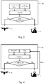
- Figure 3 shows schematically a variant of the first diagnostics sub-system 2a, in which the sub-system receives not only the sensor data but also environmental data about the environment around the target, e.g. weather conditions, operation conditions etc. Using this environmental data the first diagnostics sub-system can judge whether the environment is relatively mild or relatively harsh, and, if harsh, issue a dispatch request directly to the engineer 4 rather than to the drone 5.
- environmental data e.g. weather conditions, operation conditions etc.
- Figure 4 shows schematically a further variant of the first diagnostics sub-system 2a.
- the engineer 5 carries a location device, such as a GPS sensor, which informs the first diagnostics sub-system of the location of the engineer.
- the sub-system can again issue a dispatch request directly to the engineer 4 rather than to the drone 5. In this way, the time delay for performance of the maintenance or repair can be shortened.
- Figure 5 shows schematically a further variant of the first diagnostics sub-system 2a.
- the first diagnostics sub-system determines whether the need for maintenance or repair of the target equipment is relatively high or relatively low, i.e. it can apply an emergency threshold. When the threshold is exceeded, the first diagnostics sub-system can yet again issue a dispatch request directly to the engineer 4 rather than to the drone 5. In this way, critical failures of the target equipment 1, which may lead to accidents, are more likely to be avoided.
- the mobile robot investigator 5 equipped with one or more cameras for obtaining photographic or video image data.
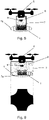
- Figure 6 shows schematically a wheeled version of the robot investigator having a camera 6.
- the robot investigator has an optical shielding structure 7 in the form of a blackout curtain which surrounds the camera and a light source 8 also located inside the blackout curtain.
- the blackout curtain and light source improve the visual inspection accuracy by enabling the camera to take its images under standardised and repeatable lighting conditions, which are then more comparable against stored images. In this way, effects of external factors which may influence image quality (brightness, precipitation, obstacles etc.) can be reduced or eliminated.
- the optical shielding structure 7 is in the form of a flexible blackout curtain which allows the mobile robot investigator 5 to move unhindered over the target equipment 1.
- Figure 7 shows schematically a variant of the wheeled robot investigator in which the shielding structure 7 is formed as a rigid-walled box having an open bottom and flexible fringes 7a around the bottom edges of the wall to allow the robot investigator to similarly move unhindered over the target equipment.
- Figure 8 shows schematically a drone form of the mobile robot investigator 5. Like the wheeled robot investigator of Figure 7 , it has a camera 6, a box-like optical shielding structure 7 with a flexible base structure 7a, and a light source 8.
- An advantage of the drone robot investigator is its high mobility, allowing it to easily approach and leave the target equipment, facilitating image capture even if the target equipment is in operation.
- Figure 9 shows schematically at top a variant of the drone robot investigator having a larger diameter shielding structure 7, and at bottom the cross-sectional footprint of the shielding structure, which is configured to provide clear spaces beneath the drone's propellers in order to avoid interference with the propellers' downdraughts.
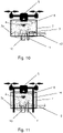
- FIG 10 shows schematically the drone mobile robot investigator 5 being used to investigate an item of target equipment which is a set of railway of points (also known as a railroad switch).
- Each set of points has a pair of static stock rails 10 and a pair of movable tongue rails 11.
- An operating rod 12 joins the tongue rails and moves them in tandem towards or away from their respective stock rails to change the points.
- the points are used for changing the tracks of rolling stock, and as such are safety critical items of equipment. Many points are deployed across a railway network, and the maintenance cost of keeping points in good working condition is high.
- manual inspection of points by an engineer can be dangerous due to the operation of tolling stock on the network.
- the drone can be positioned, as shown in Figure 10 , over a stock rail / tongue rail pair in order to evaluate the condition of that pair and the operating rod.
- the mobile robot investigator 5 may include a code reader (e.g. integrated with the camera 6) which is configured to read an identifying code 13, such as a QR code, mounted to the target equipment, and thereby identify the target equipment to the mobile robot investigator.
- the additional data obtained by the robot investigator can also be associated with the identification information when transmitted to the second diagnostics sub-system 2b, thereby helping the sub-system to organise the data.
- the code can provide the robot investigator with information, such as a stand-off information, which the robot investigator can apply to its investigation, e.g. to help it produce standardised and repeatable images.
- Figure 11 shows a further variant of the drone mobile robot investigator 5 in which the drone has depending measuring rods 14 which can be docked to the target equipment to ensure a correct stand-off of the camera 6 from the equipment.
Landscapes
- Engineering & Computer Science (AREA)
- Physics & Mathematics (AREA)
- General Physics & Mathematics (AREA)
- Automation & Control Theory (AREA)
- Manufacturing & Machinery (AREA)
- Transportation (AREA)
- Aviation & Aerospace Engineering (AREA)
- Management, Administration, Business Operations System, And Electronic Commerce (AREA)
- Control Of Position, Course, Altitude, Or Attitude Of Moving Bodies (AREA)
Abstract
Description
- The present invention relates to a diagnostics system for diagnosing the condition of target equipment.
-
Figure 1 shows schematically aconventional diagnostics system 102 for use in maintenance and repair oftarget equipment 101. The target equipment has one ormore sensors 103 that sense various measurable parameters of the equipment, the sensor data being transmitted to the diagnostics system. The data is used by the system to determine whether the condition of the equipment has deteriorated such that it requires maintenance or repair. For example, the data can be compared with look up tables or applied to analytical or learnt models of the target equipment. If the determination is positive, the system issues a request, e.g. in the form of an alarm, to call out amaintenance engineer 104 to visit the target equipment and perform appropriate maintenance or repair action. - Such an approach to diagnosis and maintenance or repair is used in many industries, such as railways, construction, automotive, energy production and supply, buildings and plant, water etc.
- However, the cost of implementing this approach, especially the human cost, can be high. In particular, to avoid equipment breakdowns caused by inadequate or ambiguous sensor data, it may be necessary to overcompensate by setting up the system to call out a maintenance engineer even when maintenance or repair eventually proves unnecessary, i.e. to accept a large number of "false positives". Also false positive alarms may be caused by external/environmental factors temporarily affecting the performance of the sensors, or the transmission of the sensor data.
- The present invention has been devised in light of the above considerations.
- In a first aspect, the present invention provides a computer-based diagnostics system for diagnosing the condition of target equipment, the diagnostics system including:
- a first diagnostics sub-system that is configured to: receive sensor data from sensors of the target equipment, make a preliminary evaluation of the condition of the target equipment on the basis of the sensor data, and, when the preliminary evaluation of the condition is indicative of a need for maintenance or repair of the target equipment, issue a request to dispatch a mobile robot investigator to the target equipment in order for the mobile robot investigator to make an investigation of the target equipment; and
- a second diagnostics sub-system that is configured to: receive from the mobile robot investigator additional data obtained by the mobile robot investigator during its investigation of the target equipment, make a further evaluation of the condition of the target equipment on the basis of the additional data, and, when the further evaluation of the condition is still indicative of a need for maintenance or repair of the target equipment, issue a request to dispatch an engineer to the target equipment in order to perform the maintenance or repair.
- By dispatch of the mobile robot investigator and using the additional data obtained thereby to make a further evaluation of the condition of the target equipment, it is possible to better discriminate between false positives and those circumstances when a human engineer is needed to perform maintenance or repair. In this way, better use can be made of human resources and costs can be reduced.
- The target equipment can be, for example, any equipment in the aforementioned industries. The system is of particular benefit in situations where there are spatially distributed pieces of target equipment which are time-consuming for an engineer to visit. It also has advantages in situations where the target equipment is in potentially dangerous locations, such that unnecessary visits by humans should be reduced. In the context of railways, the target equipment can be railway infrastructure, such as sets of points, overhead lines, and/or track circuits. In particular, sets of points are abundant on railway networks, and can be both widely spatially distributed and potentially dangerous to visit in person.
- The first diagnostics sub-system may be further configured to receive environmental data from further sensors of the target equipment and/or to receive independent environmental data to determine whether the environment of the target equipment is relatively harsh or relatively mild, and wherein the first diagnostics sub-system may issue the request to dispatch the mobile robot investigator when the environment is relatively mild, but otherwise issue a request to an engineer to make an investigation of the target equipment when the environment is relatively harsh. The environmental data can be e.g. weather data and/or operational data. For example, weather data can indicate whether there is wind or precipitation in the vicinity of the target equipment that might cause difficulties for the mobile robot investigator to obtain its additional data. Operational data can indicate whether there are operations occurring, e.g. traffic movements, in the vicinity of the target equipment that might cause difficulties for the mobile robot investigator to obtain its additional data. In either case, it can be preferable to dispatch an engineer to the target equipment immediately without recourse to the mobile robot investigator.
- The first diagnostics sub-system may be further configured to receive a location signal providing the location of an engineer, and wherein the first diagnostics sub-system may issue the request to dispatch the mobile robot investigator when the location of the engineer is further than a predetermined distance away from the target equipment, but otherwise issue a request to the engineer to make an investigation of the target equipment. The time delay for performance of the maintenance or repair can thus be shortened.
- The first diagnostics sub-system may be further configured to determine whether the need for maintenance or repair of the target equipment is relatively high or relatively low, and wherein the first diagnostics sub-system may issue the request to dispatch the mobile robot investigator when the need is relatively low, but otherwise issue a request to an engineer to make an investigation of the target equipment when the need is relatively high. Critical failures of the
target equipment 1, which may lead to accidents, are thus more likely to be avoided. - The additional data may be photographic or video image data.
- The second diagnostics sub-system may be further configured to share its further evaluation of the condition of the target equipment with the first diagnostics sub-system. The first diagnostics sub-system can then use the further evaluation to improve its ability to make the preliminary evaluation. For example, the first diagnostics sub-system may make its preliminary evaluation on the basis of a comparison of the sensor data with entries in a look up table, or on the basis of a model of the target equipment. The result of the further evaluation can be used to update such a look up table or to better tune such a model.
- In a second aspect, the present invention provides a combination of the diagnostics system of the first aspect and the mobile robot investigator.
- The mobile robot investigator may be, for example, an unmanned aerial vehicle. Such a vehicle can be highly mobile, allowing it to easily approach the target equipment, even when the target equipment is in operation.
- Conveniently, the mobile robot investigator may carry one or more cameras to obtain the additional data in the form of photographic or video data.
- The one or more cameras may be located within an optical shielding structure which is place-able over the target equipment by the mobile robot investigator to regulate the ambient lighting of the target equipment. Additionally, the mobile robot investigator may carry one or more light sources within the optical shielding structure to provide standardised lighting of the target equipment within the optical shielding structure. In this way, standardised and repeatable lighting conditions can be achieved, and as a consequence standardised images obtained which are more comparable against stored images.
- The mobile robot investigator may include means to impose a predetermined distance of the one or more cameras from the target equipment.
- The mobile robot investigator may include a code reader which is configured to read a code mounted to the target equipment. The code can provide the robot investigator with the identity of the target equipment. Additionally or alternatively, it can provide the robot investigator with information which the robot investigator can apply to its investigation, e.g. to help it produce standardised and repeatable images.
- In a third aspect, the present invention provides the use of the combination of the second aspect for performing maintenance or repair of target equipment equipped with sensors for obtaining sensor data suitable for evaluating the condition of the target equipment.
- For example, a method of performing maintenance or repair of target equipment equipped with sensors for obtaining sensor data suitable for evaluating the condition of the target equipment includes:
- providing the combination of the second aspect;
- using the first diagnostics sub-system to: receive sensor data from the sensors of the target equipment, make a preliminary evaluation of the condition of the target equipment on the basis of the sensor data, and, when the preliminary evaluation of the condition is indicative of a need for maintenance or repair of the target equipment, dispatch the mobile robot investigator to the target equipment in order for the mobile robot investigator to make an investigation of the target equipment;
- obtaining additional data by the mobile robot investigator during its investigation of the target equipment;
- using the second diagnostics sub-system to: receive from the mobile robot investigator the additional data, make a further evaluation of the condition of the target equipment on the basis of the additional data, and, when the further evaluation of the condition is still indicative of a need for maintenance or repair of the target equipment, issue a request to dispatch an engineer to the target equipment in order to perform the maintenance or repair.
- In a fourth aspect, the present invention provides a computer-based method of performing maintenance or repair of target equipment equipped with sensors for obtaining sensor data suitable for evaluating the condition of the target equipment, the method including:
- receiving sensor data from sensors of the target equipment;
- making a preliminary evaluation of the condition of the target equipment on the basis of the sensor data;
- when the preliminary evaluation of the condition is indicative of a need for maintenance or repair of the target equipment, dispatching a mobile robot investigator to the target equipment in order for the mobile robot investigator to make an investigation of the target equipment;
- receiving from the mobile robot investigator additional data obtained by the mobile robot investigator during its investigation of the target equipment;
- making a further evaluation of the condition of the target equipment on the basis of the additional data; and
- when the further evaluation of the condition is still indicative of a need for maintenance or repair of the target equipment, issuing a request to dispatch an engineer to the target equipment in order to perform the maintenance or repair.
- Thus the method of the fourth aspect corresponds to the diagnostics system of the first aspect.
- In a fifth aspect, the present invention provides a computer program comprising code which, when the code is executed on a computer, causes the computer to perform the method of the fourth aspect.
- In a sixth aspect, the present invention provides a computer readable medium storing the computer program of the fifth aspect.
- The invention includes the combination of the aspects and preferred features described except where such a combination is clearly impermissible or expressly avoided.
- Embodiments and experiments illustrating the principles of the invention will now be discussed with reference to the accompanying figures in which:
-
Figure 1 shows schematically a conventional diagnostics system for use in maintenance and repair of target equipment; -
Figure 2 shows schematically a diagnostics system according to the present disclosure for use in maintenance and repair of target equipment; -
Figure 3 shows schematically a variant of a first diagnostics sub-system of the diagnostics system ofFigure 2 ; -
Figure 4 shows schematically a further variant of the first diagnostics sub-system; -
Figure 5 shows schematically a further variant of the first diagnostics sub-system; -
Figure 6 shows schematically a wheeled robot investigator; -
Figure 7 shows schematically a variant of the wheeled robot investigator; -
Figure 8 shows schematically a drone robot investigator; -
Figure 9 shows schematically a variant of the drone robot investigator; -
Figure 10 shows schematically the drone mobile robot investigator being used to investigate a set of railway of points; and -
Figure 11 shows schematically a further variant of the drone robot investigator. - Aspects and embodiments of the present invention will now be discussed with reference to the accompanying figures. Further aspects and embodiments will be apparent to those skilled in the art.
-
Figure 2 shows schematically a diagnostics system according to the present disclosure for use in maintenance and repair oftarget equipment 1. The diagnostics system includes afirst diagnostics sub-system 2a, and asecond diagnostics sub-system 2b. The target equipment is itself equipped with one ormore sensors 3 which measure condition parameters associated with the target equipment. These measurements are relayed to the first diagnostics sub-system as sensor data. - Based on the received sensor data, the
first diagnostics sub-system 2a makes a preliminary evaluation of the condition of thetarget equipment 1. In particular, it determines if the condition has exceeded a threshold indicative of a need for maintenance or repair of the target equipment. The threshold may be a simple alert level (e.g. stored in a look up table of the first diagnostics sub-system) associated with one or more of the sensor measurements, or it may be a more sophisticated analysis based for example on a model of the target equipment stored in or interrogatable by the first diagnostics sub-system. - When the when the preliminary evaluation of the condition is indicative of a need for maintenance or repair of the target equipment, the
first diagnostics sub-system 2a then issues a request to dispatch amobile robot investigator 5 to the target equipment in order for the robot investigator to make an investigation of the target equipment. The robot investigator may conveniently be, as shown inFigure 2 , an unmanned aerial vehicle (or "drone") equipped, for example with one or more cameras for obtaining photographic or video image data. However, this does not exclude that the robot investigator could be of different type, such as a wheeled or tracked vehicle, and/or that the robot investigator can obtain other types of data rather than image data. - The
drone 5 approaches thetarget equipment 1, and using its one or more cameras obtains additional data from the target equipment in the form of image data of the target equipment, and relays this back to thesecond diagnostics sub-system 2b which then performs a further evaluation of the condition of the target equipment on the basis of the additional data. For example, the second diagnostics sub-system can perform an image analysis in which a comparison is made between the image(s) of the additional data, and stored images of the target equipment in healthy and/or deteriorated conditions. On the basis of that comparison, the second diagnostics sub-system can validate or invalidate the preliminary evaluation, i.e. determine whether the condition target equipment is still indicative of a need for maintenance or repair of the target equipment. - In the case of validation, a dispatch request is sent to an engineer to go to the
target equipment 1 to perform the maintenance or repair. Whether the result of the further evaluation is validation or invalidation, the result can be shared with thefirst diagnostics sub-system 2a, which can then advantageously use that result e.g. to improve its model of the target equipment and thereby improve the accuracy of the first diagnostics sub-system. - A further benefit of the system is that it can reduce the incidence of false positives, and thereby make better use can be made of human resources. In this way labour costs can be reduced.
- The system is particularly advantageous to implement when plural items of target equipment that may need maintenance or repair are spatially distributed so that they are time-consuming to visit and/or are in potentially dangerous locations.
-
Figure 3 shows schematically a variant of thefirst diagnostics sub-system 2a, in which the sub-system receives not only the sensor data but also environmental data about the environment around the target, e.g. weather conditions, operation conditions etc. Using this environmental data the first diagnostics sub-system can judge whether the environment is relatively mild or relatively harsh, and, if harsh, issue a dispatch request directly to theengineer 4 rather than to thedrone 5. An advantage is that the equipment inspection can be performed as soon as possible even if it would be difficult for the drone to approach the target equipment. -
Figure 4 shows schematically a further variant of thefirst diagnostics sub-system 2a. In this variant, theengineer 5 carries a location device, such as a GPS sensor, which informs the first diagnostics sub-system of the location of the engineer. When the first diagnostics sub-system determines that engineer's location is within a predetermined distance from the target equipment, the sub-system can again issue a dispatch request directly to theengineer 4 rather than to thedrone 5. In this way, the time delay for performance of the maintenance or repair can be shortened. -
Figure 5 shows schematically a further variant of thefirst diagnostics sub-system 2a. In this variant, the first diagnostics sub-system determines whether the need for maintenance or repair of the target equipment is relatively high or relatively low, i.e. it can apply an emergency threshold. When the threshold is exceeded, the first diagnostics sub-system can yet again issue a dispatch request directly to theengineer 4 rather than to thedrone 5. In this way, critical failures of thetarget equipment 1, which may lead to accidents, are more likely to be avoided. - As mentioned above, the
mobile robot investigator 5 equipped with one or more cameras for obtaining photographic or video image data.Figure 6 shows schematically a wheeled version of the robot investigator having acamera 6. In addition, however, the robot investigator has anoptical shielding structure 7 in the form of a blackout curtain which surrounds the camera and alight source 8 also located inside the blackout curtain. The blackout curtain and light source improve the visual inspection accuracy by enabling the camera to take its images under standardised and repeatable lighting conditions, which are then more comparable against stored images. In this way, effects of external factors which may influence image quality (brightness, precipitation, obstacles etc.) can be reduced or eliminated. - In
Figure 6 , theoptical shielding structure 7 is in the form of a flexible blackout curtain which allows themobile robot investigator 5 to move unhindered over thetarget equipment 1. However, other shielding structures can be adopted. For example,Figure 7 shows schematically a variant of the wheeled robot investigator in which theshielding structure 7 is formed as a rigid-walled box having an open bottom andflexible fringes 7a around the bottom edges of the wall to allow the robot investigator to similarly move unhindered over the target equipment. -
Figure 8 shows schematically a drone form of themobile robot investigator 5. Like the wheeled robot investigator ofFigure 7 , it has acamera 6, a box-likeoptical shielding structure 7 with aflexible base structure 7a, and alight source 8. An advantage of the drone robot investigator is its high mobility, allowing it to easily approach and leave the target equipment, facilitating image capture even if the target equipment is in operation.Figure 9 shows schematically at top a variant of the drone robot investigator having a largerdiameter shielding structure 7, and at bottom the cross-sectional footprint of the shielding structure, which is configured to provide clear spaces beneath the drone's propellers in order to avoid interference with the propellers' downdraughts. -
Figure 10 shows schematically the dronemobile robot investigator 5 being used to investigate an item of target equipment which is a set of railway of points (also known as a railroad switch). Each set of points has a pair ofstatic stock rails 10 and a pair of movable tongue rails 11. An operatingrod 12 joins the tongue rails and moves them in tandem towards or away from their respective stock rails to change the points. The points are used for changing the tracks of rolling stock, and as such are safety critical items of equipment. Many points are deployed across a railway network, and the maintenance cost of keeping points in good working condition is high. In addition, manual inspection of points by an engineer can be dangerous due to the operation of tolling stock on the network. Thus it can be particularly advantageous to use the diagnostics system described above to reduce the number of manual points inspections. The drone can be positioned, as shown inFigure 10 , over a stock rail / tongue rail pair in order to evaluate the condition of that pair and the operating rod. - Optionally, as shown in
Figure 10 , themobile robot investigator 5 may include a code reader (e.g. integrated with the camera 6) which is configured to read an identifyingcode 13, such as a QR code, mounted to the target equipment, and thereby identify the target equipment to the mobile robot investigator. The additional data obtained by the robot investigator can also be associated with the identification information when transmitted to thesecond diagnostics sub-system 2b, thereby helping the sub-system to organise the data. Additionally or alternatively, the code can provide the robot investigator with information, such as a stand-off information, which the robot investigator can apply to its investigation, e.g. to help it produce standardised and repeatable images. -
Figure 11 shows a further variant of the dronemobile robot investigator 5 in which the drone has depending measuringrods 14 which can be docked to the target equipment to ensure a correct stand-off of thecamera 6 from the equipment. - The features disclosed in the foregoing description, or in the following claims, or in the accompanying drawings, expressed in their specific forms or in terms of a means for performing the disclosed function, or a method or process for obtaining the disclosed results, as appropriate, may, separately, or in any combination of such features, be utilised for realising the invention in diverse forms thereof.
- While the invention has been described in conjunction with the exemplary embodiments described above, many equivalent modifications and variations will be apparent to those skilled in the art when given this disclosure. Accordingly, the exemplary embodiments of the invention set forth above are considered to be illustrative and not limiting. Various changes to the described embodiments may be made without departing from the spirit and scope of the invention.
- Any section headings used herein are for organizational purposes only and are not to be construed as limiting the subject matter described.
- Throughout this specification, including the claims which follow, unless the context requires otherwise, the word "comprise" and "include", and variations such as "comprises", "comprising", and "including" will be understood to imply the inclusion of a stated integer or step or group of integers or steps but not the exclusion of any other integer or step or group of integers or steps.
- It must be noted that, as used in the specification and the appended claims, the singular forms "a," "an," and "the" include plural referents unless the context clearly dictates otherwise.
Claims (15)
- A computer-based diagnostics system for diagnosing the condition of target equipment (1), the diagnostics system including:a first diagnostics sub-system (2a) that is configured to: receive sensor data from sensors (3) of the target equipment (1), make a preliminary evaluation of the condition of the target equipment on the basis of the sensor data, and, when the preliminary evaluation of the condition is indicative of a need for maintenance or repair of the target equipment, issue a request to dispatch a mobile robot investigator (5) to the target equipment in order for the mobile robot investigator to make an investigation of the target equipment; anda second diagnostics sub-system (2b) that is configured to: receive from the mobile robot investigator (5) additional data obtained by the mobile robot investigator during its investigation of the target equipment (1), make a further evaluation of the condition of the target equipment on the basis of the additional data, and, when the further evaluation of the condition is still indicative of a need for maintenance or repair of the target equipment, issue a request to dispatch an engineer (4) to the target equipment in order to perform the maintenance or repair.
- The diagnostics system according to claim 1, wherein the first diagnostics sub-system is further configured to receive environmental data from further sensors of the target equipment and/or to receive independent environmental data to determine whether the environment of the target equipment is relatively harsh or relatively mild, and wherein the first diagnostics sub-system issues the request to dispatch the mobile robot investigator when the environment is relatively mild, but otherwise issues a request to an engineer to make an investigation of the target equipment when the environment is relatively harsh.
- The diagnostics system according to claim 1 or 2, wherein the first diagnostics sub-system is further configured to receive a location signal providing the location of an engineer, and wherein the first diagnostics sub-system issues the request to dispatch the mobile robot investigator when the location of the engineer is further than a predetermined distance away from the target equipment, but otherwise issues a request to the engineer to make an investigation of the target equipment.
- The diagnostics system according to any one of claims 1 to 3, wherein the first diagnostics sub-system is further configured to determine whether the need for maintenance or repair of the target equipment is relatively high or relatively low, and wherein the first diagnostics sub-system issues the request to dispatch the mobile robot investigator when the need is relatively low, but otherwise issues a request to an engineer to make an investigation of the target equipment when the need is relatively high.
- The diagnostics system according to claim 1, wherein the additional data is photographic or video image data.
- A combination of the diagnostics system of any one of claims 1 to 5 and the mobile robot investigator.
- The combination of claim 6, wherein the mobile robot investigator is an unmanned aerial vehicle.
- The combination of claim 6 or 7, wherein the mobile robot investigator carries one or more cameras to obtain the additional data in the form of photographic or video data.
- The combination of claim 8, wherein the one or more cameras are located within an optical shielding structure which is place-able over the target equipment by the mobile robot investigator to regulate the ambient lighting of the target equipment.
- The combination of claim 9, wherein the mobile robot investigator carries one or more light sources within the optical shielding structure to provide standardised lighting of the target equipment within the optical shielding structure.
- The combination of any one of claims 8 to 10, wherein the mobile robot investigator includes means to impose a predetermined distance of the one or more cameras from the target equipment.
- The combination of any one of claims 6 to 11, wherein the mobile robot investigator includes a code reader which is configured to read a code mounted to the target equipment.
- Use of the combination of any one of claims 6 to 12 for performing maintenance or repair of target equipment equipped with sensors for obtaining sensor data suitable for evaluating the condition of the target equipment.
- A computer-based method of performing maintenance or repair of target equipment equipped with sensors for obtaining sensor data suitable for evaluating the condition of the target equipment, the method including:receiving sensor data from sensors of the target equipment;making a preliminary evaluation of the condition of the target equipment on the basis of the sensor data;when the preliminary evaluation of the condition is indicative of a need for maintenance or repair of the target equipment, dispatching a mobile robot investigator to the target equipment in order for the mobile robot investigator to make an investigation of the target equipment;receiving from the mobile robot investigator additional data obtained by the mobile robot investigator during its investigation of the target equipment;making a further evaluation of the condition of the target equipment on the basis of the additional data; andwhen the further evaluation of the condition is still indicative of a need for maintenance or repair of the target equipment, issuing a request to dispatch an engineer to the target equipment in order to perform the maintenance or repair.
- A computer readable medium storing a computer program comprising code which, when the code is executed on a computer, causes the computer to perform the method of claim 14.
Priority Applications (3)
| Application Number | Priority Date | Filing Date | Title |
|---|---|---|---|
| EP20212220.6A EP4009127B1 (en) | 2020-12-07 | 2020-12-07 | Diagnostics system for diagnosing the condition of equipment |
| PCT/EP2021/084053 WO2022122564A1 (en) | 2020-12-07 | 2021-12-02 | Diagnostics system for diagnosing the condition of target equipment |
| JP2023516648A JP7406673B2 (en) | 2020-12-07 | 2021-12-02 | Diagnostic system for diagnosing the condition of target equipment |
Applications Claiming Priority (1)
| Application Number | Priority Date | Filing Date | Title |
|---|---|---|---|
| EP20212220.6A EP4009127B1 (en) | 2020-12-07 | 2020-12-07 | Diagnostics system for diagnosing the condition of equipment |
Publications (2)
| Publication Number | Publication Date |
|---|---|
| EP4009127A1 true EP4009127A1 (en) | 2022-06-08 |
| EP4009127B1 EP4009127B1 (en) | 2023-01-25 |
Family
ID=73740295
Family Applications (1)
| Application Number | Title | Priority Date | Filing Date |
|---|---|---|---|
| EP20212220.6A Active EP4009127B1 (en) | 2020-12-07 | 2020-12-07 | Diagnostics system for diagnosing the condition of equipment |
Country Status (3)
| Country | Link |
|---|---|
| EP (1) | EP4009127B1 (en) |
| JP (1) | JP7406673B2 (en) |
| WO (1) | WO2022122564A1 (en) |
Families Citing this family (2)
| Publication number | Priority date | Publication date | Assignee | Title |
|---|---|---|---|---|
| CN119168613B (en) * | 2024-08-12 | 2025-08-05 | 武昌理工学院 | Intelligent construction method and device based on robot construction |
| EP4697105A1 (en) * | 2024-08-12 | 2026-02-18 | Primetals Technologies Germany GmbH | Monitoring of a plant of the primary industry |
Citations (2)
| Publication number | Priority date | Publication date | Assignee | Title |
|---|---|---|---|---|
| US20190066488A1 (en) * | 2017-08-23 | 2019-02-28 | Robert B. Locke | Building bots interfacing with intrusion detection systems |
| US20200089206A1 (en) * | 2018-10-10 | 2020-03-19 | Greenstar Research and Development India Pvt Ltd | Unmanned aerial vehicle (uav) and a system for monitoring and maintaining luminaires using the uav |
Family Cites Families (2)
| Publication number | Priority date | Publication date | Assignee | Title |
|---|---|---|---|---|
| JP2018132794A (en) * | 2017-02-13 | 2018-08-23 | 株式会社野村総合研究所 | Sharing system |
| JP6813193B2 (en) * | 2018-09-12 | 2021-01-13 | Necフィールディング株式会社 | Personnel selection device, personnel selection method and program |
-
2020
- 2020-12-07 EP EP20212220.6A patent/EP4009127B1/en active Active
-
2021
- 2021-12-02 WO PCT/EP2021/084053 patent/WO2022122564A1/en not_active Ceased
- 2021-12-02 JP JP2023516648A patent/JP7406673B2/en active Active
Patent Citations (2)
| Publication number | Priority date | Publication date | Assignee | Title |
|---|---|---|---|---|
| US20190066488A1 (en) * | 2017-08-23 | 2019-02-28 | Robert B. Locke | Building bots interfacing with intrusion detection systems |
| US20200089206A1 (en) * | 2018-10-10 | 2020-03-19 | Greenstar Research and Development India Pvt Ltd | Unmanned aerial vehicle (uav) and a system for monitoring and maintaining luminaires using the uav |
Also Published As
| Publication number | Publication date |
|---|---|
| JP7406673B2 (en) | 2023-12-27 |
| EP4009127B1 (en) | 2023-01-25 |
| JP2023542658A (en) | 2023-10-11 |
| WO2022122564A1 (en) | 2022-06-16 |
Similar Documents
| Publication | Publication Date | Title |
|---|---|---|
| US10643444B2 (en) | Facility management system using Internet of things (IoT) based sensor and unmanned aerial vehicle (UAV), and method for the same | |
| US10563976B2 (en) | Method and system for detecting a gauge of a metro vehicle | |
| US8150105B2 (en) | Inspection using three-dimensional profile information | |
| CN105799740B (en) | A kind of track foreign body intrusion automatic detection and method for early warning based on technology of Internet of things | |
| CN111507560B (en) | Tram vehicle base road turnout health management system | |
| US11335036B2 (en) | Image synthesizing system and image synthesizing method | |
| CN104567725A (en) | Vehicle operation fault detection system and method | |
| EP4009127B1 (en) | Diagnostics system for diagnosing the condition of equipment | |
| KR102053918B1 (en) | Unmanned vehicle, system and method for inspecting railway facilities using unmanned vehicle | |
| CN115373403B (en) | Inspection service system for construction machinery equipment | |
| CN114248819A (en) | Railway intrusion foreign matter unmanned aerial vehicle detection method, device and system based on deep learning | |
| CN113933856A (en) | System, method and device for detecting residues at bottom of railway wagon | |
| CN120462476A (en) | Electric locomotive track obstacle identification method, device, system and electronic equipment | |
| Sasikala et al. | Train bogie part recognition with multi-object multi-template matching adaptive algorithm | |
| KR102556878B1 (en) | Concrete facility maintenance system that performs condition evaluation using drones based on autonomous flight in shaded areas | |
| CN112585484B (en) | Methods and components for identifying corona discharges in facilities with operating equipment | |
| CN111959562A (en) | Safety protection early warning method, device and system for railway on-road operators | |
| US20240212116A1 (en) | Deterioration diagnosis device, deterioration diagnosis method, and recording medium | |
| CN117746288A (en) | Vehicle weight prediction, sample data construction and model training method and device | |
| WO2019044345A1 (en) | Railway equipment monitoring device and railway equipment monitoring system | |
| CN115856980B (en) | Marshalling station operator monitoring method and system | |
| RU2793867C1 (en) | System for monitoring readiness of front to carry out the machine alignment of the railway track | |
| Guha et al. | An automatic accident detection system for trains using onboard monitoring system | |
| CN121542987A (en) | A method and device for real-time detection of track defects | |
| CN120612673A (en) | Obstacle identification method, device, equipment and rail crane |
Legal Events
| Date | Code | Title | Description |
|---|---|---|---|
| PUAI | Public reference made under article 153(3) epc to a published international application that has entered the european phase |
Free format text: ORIGINAL CODE: 0009012 |
|
| STAA | Information on the status of an ep patent application or granted ep patent |
Free format text: STATUS: EXAMINATION IS IN PROGRESS |
|
| 17P | Request for examination filed |
Effective date: 20201207 |
|
| AK | Designated contracting states |
Kind code of ref document: A1 Designated state(s): AL AT BE BG CH CY CZ DE DK EE ES FI FR GB GR HR HU IE IS IT LI LT LU LV MC MK MT NL NO PL PT RO RS SE SI SK SM TR |
|
| REG | Reference to a national code |
Ref country code: DE Ref legal event code: R079 Ref document number: 602020007828 Country of ref document: DE Free format text: PREVIOUS MAIN CLASS: G05B0023020000 Ipc: B64F0005600000 |
|
| GRAP | Despatch of communication of intention to grant a patent |
Free format text: ORIGINAL CODE: EPIDOSNIGR1 |
|
| RIC1 | Information provided on ipc code assigned before grant |
Ipc: B64C 39/02 20060101ALI20220714BHEP Ipc: G05B 23/02 20060101ALI20220714BHEP Ipc: B64F 5/60 20170101AFI20220714BHEP |
|
| STAA | Information on the status of an ep patent application or granted ep patent |
Free format text: STATUS: GRANT OF PATENT IS INTENDED |
|
| INTG | Intention to grant announced |
Effective date: 20220818 |
|
| GRAS | Grant fee paid |
Free format text: ORIGINAL CODE: EPIDOSNIGR3 |
|
| GRAA | (expected) grant |
Free format text: ORIGINAL CODE: 0009210 |
|
| STAA | Information on the status of an ep patent application or granted ep patent |
Free format text: STATUS: THE PATENT HAS BEEN GRANTED |
|
| AK | Designated contracting states |
Kind code of ref document: B1 Designated state(s): AL AT BE BG CH CY CZ DE DK EE ES FI FR GB GR HR HU IE IS IT LI LT LU LV MC MK MT NL NO PL PT RO RS SE SI SK SM TR |
|
| REG | Reference to a national code |
Ref country code: GB Ref legal event code: FG4D |
|
| REG | Reference to a national code |
Ref country code: CH Ref legal event code: EP |
|
| REG | Reference to a national code |
Ref country code: AT Ref legal event code: REF Ref document number: 1545766 Country of ref document: AT Kind code of ref document: T Effective date: 20230215 Ref country code: IE Ref legal event code: FG4D |
|
| REG | Reference to a national code |
Ref country code: DE Ref legal event code: R096 Ref document number: 602020007828 Country of ref document: DE |
|
| REG | Reference to a national code |
Ref country code: LT Ref legal event code: MG9D |
|
| REG | Reference to a national code |
Ref country code: NL Ref legal event code: MP Effective date: 20230125 |
|
| REG | Reference to a national code |
Ref country code: AT Ref legal event code: MK05 Ref document number: 1545766 Country of ref document: AT Kind code of ref document: T Effective date: 20230125 |
|
| PG25 | Lapsed in a contracting state [announced via postgrant information from national office to epo] |
Ref country code: NL Free format text: LAPSE BECAUSE OF FAILURE TO SUBMIT A TRANSLATION OF THE DESCRIPTION OR TO PAY THE FEE WITHIN THE PRESCRIBED TIME-LIMIT Effective date: 20230125 |
|
| PG25 | Lapsed in a contracting state [announced via postgrant information from national office to epo] |
Ref country code: RS Free format text: LAPSE BECAUSE OF FAILURE TO SUBMIT A TRANSLATION OF THE DESCRIPTION OR TO PAY THE FEE WITHIN THE PRESCRIBED TIME-LIMIT Effective date: 20230125 Ref country code: PT Free format text: LAPSE BECAUSE OF FAILURE TO SUBMIT A TRANSLATION OF THE DESCRIPTION OR TO PAY THE FEE WITHIN THE PRESCRIBED TIME-LIMIT Effective date: 20230525 Ref country code: NO Free format text: LAPSE BECAUSE OF FAILURE TO SUBMIT A TRANSLATION OF THE DESCRIPTION OR TO PAY THE FEE WITHIN THE PRESCRIBED TIME-LIMIT Effective date: 20230425 Ref country code: LV Free format text: LAPSE BECAUSE OF FAILURE TO SUBMIT A TRANSLATION OF THE DESCRIPTION OR TO PAY THE FEE WITHIN THE PRESCRIBED TIME-LIMIT Effective date: 20230125 Ref country code: LT Free format text: LAPSE BECAUSE OF FAILURE TO SUBMIT A TRANSLATION OF THE DESCRIPTION OR TO PAY THE FEE WITHIN THE PRESCRIBED TIME-LIMIT Effective date: 20230125 Ref country code: HR Free format text: LAPSE BECAUSE OF FAILURE TO SUBMIT A TRANSLATION OF THE DESCRIPTION OR TO PAY THE FEE WITHIN THE PRESCRIBED TIME-LIMIT Effective date: 20230125 Ref country code: ES Free format text: LAPSE BECAUSE OF FAILURE TO SUBMIT A TRANSLATION OF THE DESCRIPTION OR TO PAY THE FEE WITHIN THE PRESCRIBED TIME-LIMIT Effective date: 20230125 Ref country code: AT Free format text: LAPSE BECAUSE OF FAILURE TO SUBMIT A TRANSLATION OF THE DESCRIPTION OR TO PAY THE FEE WITHIN THE PRESCRIBED TIME-LIMIT Effective date: 20230125 |
|
| PG25 | Lapsed in a contracting state [announced via postgrant information from national office to epo] |
Ref country code: SE Free format text: LAPSE BECAUSE OF FAILURE TO SUBMIT A TRANSLATION OF THE DESCRIPTION OR TO PAY THE FEE WITHIN THE PRESCRIBED TIME-LIMIT Effective date: 20230125 Ref country code: PL Free format text: LAPSE BECAUSE OF FAILURE TO SUBMIT A TRANSLATION OF THE DESCRIPTION OR TO PAY THE FEE WITHIN THE PRESCRIBED TIME-LIMIT Effective date: 20230125 Ref country code: IS Free format text: LAPSE BECAUSE OF FAILURE TO SUBMIT A TRANSLATION OF THE DESCRIPTION OR TO PAY THE FEE WITHIN THE PRESCRIBED TIME-LIMIT Effective date: 20230525 Ref country code: GR Free format text: LAPSE BECAUSE OF FAILURE TO SUBMIT A TRANSLATION OF THE DESCRIPTION OR TO PAY THE FEE WITHIN THE PRESCRIBED TIME-LIMIT Effective date: 20230426 Ref country code: FI Free format text: LAPSE BECAUSE OF FAILURE TO SUBMIT A TRANSLATION OF THE DESCRIPTION OR TO PAY THE FEE WITHIN THE PRESCRIBED TIME-LIMIT Effective date: 20230125 |
|
| REG | Reference to a national code |
Ref country code: DE Ref legal event code: R097 Ref document number: 602020007828 Country of ref document: DE |
|
| PG25 | Lapsed in a contracting state [announced via postgrant information from national office to epo] |
Ref country code: SM Free format text: LAPSE BECAUSE OF FAILURE TO SUBMIT A TRANSLATION OF THE DESCRIPTION OR TO PAY THE FEE WITHIN THE PRESCRIBED TIME-LIMIT Effective date: 20230125 Ref country code: RO Free format text: LAPSE BECAUSE OF FAILURE TO SUBMIT A TRANSLATION OF THE DESCRIPTION OR TO PAY THE FEE WITHIN THE PRESCRIBED TIME-LIMIT Effective date: 20230125 Ref country code: EE Free format text: LAPSE BECAUSE OF FAILURE TO SUBMIT A TRANSLATION OF THE DESCRIPTION OR TO PAY THE FEE WITHIN THE PRESCRIBED TIME-LIMIT Effective date: 20230125 Ref country code: DK Free format text: LAPSE BECAUSE OF FAILURE TO SUBMIT A TRANSLATION OF THE DESCRIPTION OR TO PAY THE FEE WITHIN THE PRESCRIBED TIME-LIMIT Effective date: 20230125 Ref country code: CZ Free format text: LAPSE BECAUSE OF FAILURE TO SUBMIT A TRANSLATION OF THE DESCRIPTION OR TO PAY THE FEE WITHIN THE PRESCRIBED TIME-LIMIT Effective date: 20230125 |
|
| PG25 | Lapsed in a contracting state [announced via postgrant information from national office to epo] |
Ref country code: SK Free format text: LAPSE BECAUSE OF FAILURE TO SUBMIT A TRANSLATION OF THE DESCRIPTION OR TO PAY THE FEE WITHIN THE PRESCRIBED TIME-LIMIT Effective date: 20230125 |
|
| PLBE | No opposition filed within time limit |
Free format text: ORIGINAL CODE: 0009261 |
|
| STAA | Information on the status of an ep patent application or granted ep patent |
Free format text: STATUS: NO OPPOSITION FILED WITHIN TIME LIMIT |
|
| 26N | No opposition filed |
Effective date: 20231026 |
|
| PG25 | Lapsed in a contracting state [announced via postgrant information from national office to epo] |
Ref country code: SI Free format text: LAPSE BECAUSE OF FAILURE TO SUBMIT A TRANSLATION OF THE DESCRIPTION OR TO PAY THE FEE WITHIN THE PRESCRIBED TIME-LIMIT Effective date: 20230125 |
|
| REG | Reference to a national code |
Ref country code: DE Ref legal event code: R119 Ref document number: 602020007828 Country of ref document: DE |
|
| REG | Reference to a national code |
Ref country code: CH Ref legal event code: PL |
|
| PG25 | Lapsed in a contracting state [announced via postgrant information from national office to epo] |
Ref country code: LU Free format text: LAPSE BECAUSE OF NON-PAYMENT OF DUE FEES Effective date: 20231207 |
|
| PG25 | Lapsed in a contracting state [announced via postgrant information from national office to epo] |
Ref country code: MC Free format text: LAPSE BECAUSE OF FAILURE TO SUBMIT A TRANSLATION OF THE DESCRIPTION OR TO PAY THE FEE WITHIN THE PRESCRIBED TIME-LIMIT Effective date: 20230125 |
|
| REG | Reference to a national code |
Ref country code: BE Ref legal event code: MM Effective date: 20231231 |
|
| PG25 | Lapsed in a contracting state [announced via postgrant information from national office to epo] |
Ref country code: MC Free format text: LAPSE BECAUSE OF FAILURE TO SUBMIT A TRANSLATION OF THE DESCRIPTION OR TO PAY THE FEE WITHIN THE PRESCRIBED TIME-LIMIT Effective date: 20230125 Ref country code: LU Free format text: LAPSE BECAUSE OF NON-PAYMENT OF DUE FEES Effective date: 20231207 |
|
| REG | Reference to a national code |
Ref country code: IE Ref legal event code: MM4A |
|
| PG25 | Lapsed in a contracting state [announced via postgrant information from national office to epo] |
Ref country code: DE Free format text: LAPSE BECAUSE OF NON-PAYMENT OF DUE FEES Effective date: 20240702 Ref country code: IE Free format text: LAPSE BECAUSE OF NON-PAYMENT OF DUE FEES Effective date: 20231207 |
|
| PG25 | Lapsed in a contracting state [announced via postgrant information from national office to epo] |
Ref country code: BE Free format text: LAPSE BECAUSE OF NON-PAYMENT OF DUE FEES Effective date: 20231231 |
|
| PG25 | Lapsed in a contracting state [announced via postgrant information from national office to epo] |
Ref country code: FR Free format text: LAPSE BECAUSE OF NON-PAYMENT OF DUE FEES Effective date: 20231231 |
|
| PG25 | Lapsed in a contracting state [announced via postgrant information from national office to epo] |
Ref country code: CH Free format text: LAPSE BECAUSE OF NON-PAYMENT OF DUE FEES Effective date: 20231231 |
|
| PG25 | Lapsed in a contracting state [announced via postgrant information from national office to epo] |
Ref country code: IE Free format text: LAPSE BECAUSE OF NON-PAYMENT OF DUE FEES Effective date: 20231207 Ref country code: FR Free format text: LAPSE BECAUSE OF NON-PAYMENT OF DUE FEES Effective date: 20231231 Ref country code: DE Free format text: LAPSE BECAUSE OF NON-PAYMENT OF DUE FEES Effective date: 20240702 Ref country code: CH Free format text: LAPSE BECAUSE OF NON-PAYMENT OF DUE FEES Effective date: 20231231 Ref country code: BE Free format text: LAPSE BECAUSE OF NON-PAYMENT OF DUE FEES Effective date: 20231231 |
|
| PG25 | Lapsed in a contracting state [announced via postgrant information from national office to epo] |
Ref country code: BG Free format text: LAPSE BECAUSE OF FAILURE TO SUBMIT A TRANSLATION OF THE DESCRIPTION OR TO PAY THE FEE WITHIN THE PRESCRIBED TIME-LIMIT Effective date: 20230125 |
|
| PG25 | Lapsed in a contracting state [announced via postgrant information from national office to epo] |
Ref country code: BG Free format text: LAPSE BECAUSE OF FAILURE TO SUBMIT A TRANSLATION OF THE DESCRIPTION OR TO PAY THE FEE WITHIN THE PRESCRIBED TIME-LIMIT Effective date: 20230125 |
|
| PG25 | Lapsed in a contracting state [announced via postgrant information from national office to epo] |
Ref country code: CY Free format text: LAPSE BECAUSE OF FAILURE TO SUBMIT A TRANSLATION OF THE DESCRIPTION OR TO PAY THE FEE WITHIN THE PRESCRIBED TIME-LIMIT; INVALID AB INITIO Effective date: 20201207 |
|
| PG25 | Lapsed in a contracting state [announced via postgrant information from national office to epo] |
Ref country code: HU Free format text: LAPSE BECAUSE OF FAILURE TO SUBMIT A TRANSLATION OF THE DESCRIPTION OR TO PAY THE FEE WITHIN THE PRESCRIBED TIME-LIMIT; INVALID AB INITIO Effective date: 20201207 |
|
| PG25 | Lapsed in a contracting state [announced via postgrant information from national office to epo] |
Ref country code: TR Free format text: LAPSE BECAUSE OF FAILURE TO SUBMIT A TRANSLATION OF THE DESCRIPTION OR TO PAY THE FEE WITHIN THE PRESCRIBED TIME-LIMIT Effective date: 20230125 |
|
| PGFP | Annual fee paid to national office [announced via postgrant information from national office to epo] |
Ref country code: GB Payment date: 20251120 Year of fee payment: 6 |
|
| PGFP | Annual fee paid to national office [announced via postgrant information from national office to epo] |
Ref country code: IT Payment date: 20251119 Year of fee payment: 6 |