EP4009077A2 - Vehicle location information correction based on another vehicle - Google Patents
Vehicle location information correction based on another vehicle Download PDFInfo
- Publication number
- EP4009077A2 EP4009077A2 EP21199742.4A EP21199742A EP4009077A2 EP 4009077 A2 EP4009077 A2 EP 4009077A2 EP 21199742 A EP21199742 A EP 21199742A EP 4009077 A2 EP4009077 A2 EP 4009077A2
- Authority
- EP
- European Patent Office
- Prior art keywords
- vehicle
- location
- sections
- determining
- correction factor
- Prior art date
- Legal status (The legal status is an assumption and is not a legal conclusion. Google has not performed a legal analysis and makes no representation as to the accuracy of the status listed.)
- Pending
Links
Images


Classifications
-
- G—PHYSICS
- G01—MEASURING; TESTING
- G01S—RADIO DIRECTION-FINDING; RADIO NAVIGATION; DETERMINING DISTANCE OR VELOCITY BY USE OF RADIO WAVES; LOCATING OR PRESENCE-DETECTING BY USE OF THE REFLECTION OR RERADIATION OF RADIO WAVES; ANALOGOUS ARRANGEMENTS USING OTHER WAVES
- G01S5/00—Position-fixing by co-ordinating two or more direction or position line determinations; Position-fixing by co-ordinating two or more distance determinations
- G01S5/0009—Transmission of position information to remote stations
- G01S5/0072—Transmission between mobile stations, e.g. anti-collision systems
-
- G—PHYSICS
- G05—CONTROLLING; REGULATING
- G05D—SYSTEMS FOR CONTROLLING OR REGULATING NON-ELECTRIC VARIABLES
- G05D1/00—Control of position, course, altitude or attitude of land, water, air or space vehicles, e.g. using automatic pilots
- G05D1/02—Control of position or course in two dimensions
- G05D1/021—Control of position or course in two dimensions specially adapted to land vehicles
- G05D1/0276—Control of position or course in two dimensions specially adapted to land vehicles using signals provided by a source external to the vehicle
- G05D1/0278—Control of position or course in two dimensions specially adapted to land vehicles using signals provided by a source external to the vehicle using satellite positioning signals, e.g. GPS
-
- G—PHYSICS
- G01—MEASURING; TESTING
- G01S—RADIO DIRECTION-FINDING; RADIO NAVIGATION; DETERMINING DISTANCE OR VELOCITY BY USE OF RADIO WAVES; LOCATING OR PRESENCE-DETECTING BY USE OF THE REFLECTION OR RERADIATION OF RADIO WAVES; ANALOGOUS ARRANGEMENTS USING OTHER WAVES
- G01S13/00—Systems using the reflection or reradiation of radio waves, e.g. radar systems; Analogous systems using reflection or reradiation of waves whose nature or wavelength is irrelevant or unspecified
- G01S13/86—Combinations of radar systems with non-radar systems, e.g. sonar, direction finder
-
- G—PHYSICS
- G01—MEASURING; TESTING
- G01S—RADIO DIRECTION-FINDING; RADIO NAVIGATION; DETERMINING DISTANCE OR VELOCITY BY USE OF RADIO WAVES; LOCATING OR PRESENCE-DETECTING BY USE OF THE REFLECTION OR RERADIATION OF RADIO WAVES; ANALOGOUS ARRANGEMENTS USING OTHER WAVES
- G01S19/00—Satellite radio beacon positioning systems; Determining position, velocity or attitude using signals transmitted by such systems
- G01S19/38—Determining a navigation solution using signals transmitted by a satellite radio beacon positioning system
- G01S19/39—Determining a navigation solution using signals transmitted by a satellite radio beacon positioning system the satellite radio beacon positioning system transmitting time-stamped messages, e.g. GPS [Global Positioning System], GLONASS [Global Orbiting Navigation Satellite System] or GALILEO
- G01S19/40—Correcting position, velocity or attitude
-
- G—PHYSICS
- G01—MEASURING; TESTING
- G01S—RADIO DIRECTION-FINDING; RADIO NAVIGATION; DETERMINING DISTANCE OR VELOCITY BY USE OF RADIO WAVES; LOCATING OR PRESENCE-DETECTING BY USE OF THE REFLECTION OR RERADIATION OF RADIO WAVES; ANALOGOUS ARRANGEMENTS USING OTHER WAVES
- G01S19/00—Satellite radio beacon positioning systems; Determining position, velocity or attitude using signals transmitted by such systems
- G01S19/38—Determining a navigation solution using signals transmitted by a satellite radio beacon positioning system
- G01S19/39—Determining a navigation solution using signals transmitted by a satellite radio beacon positioning system the satellite radio beacon positioning system transmitting time-stamped messages, e.g. GPS [Global Positioning System], GLONASS [Global Orbiting Navigation Satellite System] or GALILEO
- G01S19/40—Correcting position, velocity or attitude
- G01S19/41—Differential correction, e.g. DGPS [differential GPS]
-
- G—PHYSICS
- G01—MEASURING; TESTING
- G01S—RADIO DIRECTION-FINDING; RADIO NAVIGATION; DETERMINING DISTANCE OR VELOCITY BY USE OF RADIO WAVES; LOCATING OR PRESENCE-DETECTING BY USE OF THE REFLECTION OR RERADIATION OF RADIO WAVES; ANALOGOUS ARRANGEMENTS USING OTHER WAVES
- G01S19/00—Satellite radio beacon positioning systems; Determining position, velocity or attitude using signals transmitted by such systems
- G01S19/38—Determining a navigation solution using signals transmitted by a satellite radio beacon positioning system
- G01S19/39—Determining a navigation solution using signals transmitted by a satellite radio beacon positioning system the satellite radio beacon positioning system transmitting time-stamped messages, e.g. GPS [Global Positioning System], GLONASS [Global Orbiting Navigation Satellite System] or GALILEO
- G01S19/42—Determining position
- G01S19/48—Determining position by combining or switching between position solutions derived from the satellite radio beacon positioning system and position solutions derived from a further system
-
- G—PHYSICS
- G05—CONTROLLING; REGULATING
- G05D—SYSTEMS FOR CONTROLLING OR REGULATING NON-ELECTRIC VARIABLES
- G05D1/00—Control of position, course, altitude or attitude of land, water, air or space vehicles, e.g. using automatic pilots
- G05D1/02—Control of position or course in two dimensions
- G05D1/021—Control of position or course in two dimensions specially adapted to land vehicles
- G05D1/0276—Control of position or course in two dimensions specially adapted to land vehicles using signals provided by a source external to the vehicle
- G05D1/028—Control of position or course in two dimensions specially adapted to land vehicles using signals provided by a source external to the vehicle using a RF signal
-
- G—PHYSICS
- G05—CONTROLLING; REGULATING
- G05D—SYSTEMS FOR CONTROLLING OR REGULATING NON-ELECTRIC VARIABLES
- G05D1/00—Control of position, course, altitude or attitude of land, water, air or space vehicles, e.g. using automatic pilots
- G05D1/20—Control system inputs
- G05D1/24—Arrangements for determining position or orientation
- G05D1/247—Arrangements for determining position or orientation using signals provided by artificial sources external to the vehicle, e.g. navigation beacons
-
- G—PHYSICS
- G05—CONTROLLING; REGULATING
- G05D—SYSTEMS FOR CONTROLLING OR REGULATING NON-ELECTRIC VARIABLES
- G05D1/00—Control of position, course, altitude or attitude of land, water, air or space vehicles, e.g. using automatic pilots
- G05D1/20—Control system inputs
- G05D1/24—Arrangements for determining position or orientation
- G05D1/247—Arrangements for determining position or orientation using signals provided by artificial sources external to the vehicle, e.g. navigation beacons
- G05D1/248—Arrangements for determining position or orientation using signals provided by artificial sources external to the vehicle, e.g. navigation beacons generated by satellites, e.g. GPS
-
- G—PHYSICS
- G01—MEASURING; TESTING
- G01S—RADIO DIRECTION-FINDING; RADIO NAVIGATION; DETERMINING DISTANCE OR VELOCITY BY USE OF RADIO WAVES; LOCATING OR PRESENCE-DETECTING BY USE OF THE REFLECTION OR RERADIATION OF RADIO WAVES; ANALOGOUS ARRANGEMENTS USING OTHER WAVES
- G01S15/00—Systems using the reflection or reradiation of acoustic waves, e.g. sonar systems
- G01S15/86—Combinations of sonar systems with lidar systems; Combinations of sonar systems with systems not using wave reflection
-
- G—PHYSICS
- G01—MEASURING; TESTING
- G01S—RADIO DIRECTION-FINDING; RADIO NAVIGATION; DETERMINING DISTANCE OR VELOCITY BY USE OF RADIO WAVES; LOCATING OR PRESENCE-DETECTING BY USE OF THE REFLECTION OR RERADIATION OF RADIO WAVES; ANALOGOUS ARRANGEMENTS USING OTHER WAVES
- G01S17/00—Systems using the reflection or reradiation of electromagnetic waves other than radio waves, e.g. lidar systems
- G01S17/86—Combinations of lidar systems with systems other than lidar, radar or sonar, e.g. with direction finders
-
- G—PHYSICS
- G01—MEASURING; TESTING
- G01S—RADIO DIRECTION-FINDING; RADIO NAVIGATION; DETERMINING DISTANCE OR VELOCITY BY USE OF RADIO WAVES; LOCATING OR PRESENCE-DETECTING BY USE OF THE REFLECTION OR RERADIATION OF RADIO WAVES; ANALOGOUS ARRANGEMENTS USING OTHER WAVES
- G01S19/00—Satellite radio beacon positioning systems; Determining position, velocity or attitude using signals transmitted by such systems
- G01S19/38—Determining a navigation solution using signals transmitted by a satellite radio beacon positioning system
- G01S19/39—Determining a navigation solution using signals transmitted by a satellite radio beacon positioning system the satellite radio beacon positioning system transmitting time-stamped messages, e.g. GPS [Global Positioning System], GLONASS [Global Orbiting Navigation Satellite System] or GALILEO
- G01S19/396—Determining accuracy or reliability of position or pseudorange measurements
-
- G—PHYSICS
- G01—MEASURING; TESTING
- G01S—RADIO DIRECTION-FINDING; RADIO NAVIGATION; DETERMINING DISTANCE OR VELOCITY BY USE OF RADIO WAVES; LOCATING OR PRESENCE-DETECTING BY USE OF THE REFLECTION OR RERADIATION OF RADIO WAVES; ANALOGOUS ARRANGEMENTS USING OTHER WAVES
- G01S13/00—Systems using the reflection or reradiation of radio waves, e.g. radar systems; Analogous systems using reflection or reradiation of waves whose nature or wavelength is irrelevant or unspecified
- G01S13/88—Radar or analogous systems specially adapted for specific applications
- G01S13/93—Radar or analogous systems specially adapted for specific applications for anti-collision purposes
- G01S13/931—Radar or analogous systems specially adapted for specific applications for anti-collision purposes of land vehicles
- G01S2013/9316—Radar or analogous systems specially adapted for specific applications for anti-collision purposes of land vehicles combined with communication equipment with other vehicles or with base stations
Definitions
- Modern automotive vehicles include an increasing amount of electronic technology, such as sensors or detectors that provide driver assistance or autonomous vehicle control.
- Information regarding the movement or heading direction of the vehicle is useful or necessary for such assistance or control.
- GNSS satellite technology allows for determining and tracking vehicle movement or direction information based on detecting multiple satellites and using known algorithms.
- the satellite signals may not allow for a location determination with a desired accuracy.
- atmospheric delays can introduce differential error that affects the pseudo range determined from a satellite, which introduces inaccuracies into a location determination.
- An illustrative example embodiment of a system for determining vehicle location information includes at least one receiver that is configured to be supported on a first vehicle.
- the receiver is configured to receive a communication from a second vehicle and a signal from each of a plurality of satellites.
- At least one detector is supported on the first vehicle. The detector is configured to detect a positional relationship between the first vehicle and the second vehicle.
- At least one processor is associated with the first vehicle and is configured to determine a location of the first vehicle based on satellite signals received by the receiver, a location of the second vehicle based on the communication received from the second vehicle, a corrected location of the first vehicle based on the location of the second vehicle and the positional relationship between the first vehicle and the second vehicle, and a corrective mapping of a plurality of sections of a field of view of the receiver. Each of the sections has an associated correction factor that the processor uses for correcting a subsequently determined location of the first vehicle based on satellite signals received from satellites appearing in the respective sections.
- the associated correction factor for a first one of the sections is different than the associated correction factor for a second one of the sections.
- the at least one receiver comprises a first antenna for receiving the communication from the second vehicle and a second antenna for receiving the signal from each of the plurality of satellites; and the corrective mapping is for the field of view of the second antenna.
- the communication from the second vehicle includes an indication of: the location of the second vehicle, a reliability of the location of the second vehicle, a speed of the second vehicle, a size of the second vehicle, and a shape of at least a portion of the second vehicle.
- the communication from the second vehicle comprises a basic safety message (BSM) that includes an indication of a reliability of the location of the second vehicle.
- BSM basic safety message
- the at least one detector comprises at least one of a RADAR detector, a LIDAR detector, a vision based detector, or an ultrasound detector.
- the at least one processor updates the corrective mapping based on a subsequently determined location of the first vehicle based on subsequently received satellite signals, a subsequently determined location of the second vehicle based on a subsequently received communication from the second vehicle, and a subsequently determined corrected location of the first vehicle; and replaces the corrective mapping with the updated corrective mapping.
- the at least one processor either updates or dismisses the corrective mapping within a predetermined time.
- the associated correction factors each have a value; the value of the associated correction factor varies across the respective section; the value of the associated correction factor for a first one of the sections gradually changes toward a value of the associated correction factor for a second one of the sections near a transition between the first one of the sections and the second one of the sections; and the second one of the sections is adjacent the first one of the sections.
- the at least one processor determines whether the second vehicle is within a predetermined range of the first vehicle as a prerequisite to using the received communication from the second vehicle.
- An illustrative example embodiment of a method of determining location information of a first vehicle includes: receiving a communication from a second vehicle; receiving a signal from each of a plurality of satellites by at least one receiver associated with the first vehicle; detecting a positional relationship between the first vehicle and the second vehicle; determining a location of the first vehicle based on the received satellite signals; determining a location of the second vehicle based on the received communication; determining a corrected location of the first vehicle based on the location of the second vehicle and the positional relationship between the first vehicle and the second vehicle; and determining a corrective mapping of a plurality of sections of a field of view of the at least one receiver, each of the sections having an associated correction factor for correcting a subsequently determined location of the first vehicle based on satellite signals received from satellites appearing in the respective sections.
- the associated correction factor for a first one of the sections is different than the associated correction factor for a second one of the sections.
- the communication from the second vehicle includes an indication of: the location of the second vehicle, a reliability of the location of the second vehicle, a speed of the second vehicle, a size of the second vehicle, and a shape of at least a portion of the second vehicle.
- the communication from the second vehicle comprises a basic safety message (BSM) that includes an indication of a reliability of the location of the second vehicle.
- BSM basic safety message
- An example embodiment having at least feature of the method of any of the previous paragraphs includes updating the corrective mapping based on a subsequently determined location of the first vehicle based on subsequently received satellite signals, a subsequently determined location of the second vehicle based on a subsequently received communication from the second vehicle, and a subsequently determined corrected location of the first vehicle; and replacing the corrective mapping with the updated corrective mapping.
- An example embodiment having at least feature of the method of any of the previous paragraphs includes either updating or dismissing the corrective mapping within a predetermined time.
- the associated correction factors each have a value; the value of the associated correction factor varies across the respective section; the value of the associated correction factor for a first one of the sections gradually changes toward a value of the associated correction factor for a second one of the sections near a transition between the first one of the sections and the second one of the sections; and the second one of the sections is adjacent the first one of the sections.
- An example embodiment having at least feature of the method of any of the previous paragraphs includes determining whether the second vehicle is within a predetermined range of the first vehicle as a prerequisite to using the received communication from the second vehicle.
- a system for determining vehicle location information includes: receiver means, configured to be supported on a first vehicle, for receiving a communication from a second vehicle and a signal from each of a plurality of satellites; detector means, supported on the first vehicle, for detecting a positional relationship between the first vehicle and the second vehicle; and means, associated with the first vehicle, for determining: a location of the first vehicle based on satellite signals received by the receiver means, a location of the second vehicle based on the communication received by the receiver means, a corrected location of the first vehicle based on the location of the second vehicle and the positional relationship between the first vehicle and the second vehicle, and a corrective mapping of a plurality of sections of a field of view of the receiver means, each of the sections having an associated correction factor that the means for determining uses for correcting a subsequently determined location of the first vehicle based on satellite signals received from satellites appearing in the respective sections.
- the means for determining is further for determining whether the second vehicle is within a predetermined range of the first vehicle as a prerequisite to using the received communication from the second vehicle; and either updating or dismissing the corrective mapping within a predetermined time.
- FIG 1 schematically illustrates a system 20 on a first vehicle 22 for determining vehicle location information.
- the system 20 includes at least one receiver including at least one antenna 24 that is configured for receiving a signal from each of a plurality of satellites 26 and 28. Two satellites are illustrated for discussion purposes. In many circumstances, signals from more than two satellites will be received by the antenna 24.
- the example receiver includes another antenna 30 that is configured for receiving communications from a second vehicle 32..
- the receivers are transceivers in the illustrated embodiment, which include two-way communication capability.
- the communications received by the antenna 30 are vehicle-to-vehicle (V2V) communications, cellular vehicle to vehicle (C-V2V) communications or dedicated short range communications (DSRC).
- V2V vehicle-to-vehicle
- C-V2V cellular vehicle to vehicle
- DSRC dedicated short range communications
- the system 20 associated with the first vehicle 22 includes at least one detector 40 that is configured for detecting a positional relationship between the first vehicle 22 and the second vehicle 32.
- the detector 40 in some embodiments includes a RADAR detector. In other embodiments the detector 40 includes a LIDAR detector, an ultrasound detector, or a vision based detector.
- a processor 42 receives an indication regarding the detected satellite signals, the communication from the second vehicle 32 and the detected positional relationship between the vehicles 22 and 32.
- the processor 42 determines vehicle location information regarding the location of the first vehicle 22 based on those indications.
- the processor 42 is capable of correcting potential inaccuracies in the location of the first vehicle 22 that may occur if only the satellite signals received by the antenna 24 are used for determining the location of the first vehicle 22.
- the second vehicle 32 includes a system 20' that is functionally the same as the system 20 on the first vehicle 22.
- the system 20' includes a receiver comprising an antenna 25 configured for receiving a signal from the satellites 26 and 28.
- Another receiver portion includes an antenna 31 configured for vehicle-to-vehicle communications.
- a detector 41 is like the detector 40 and a processor 43 is like the processor 42.
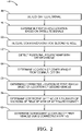
- Figure 2 includes a flowchart diagram 44 that summarizes an example approach for determining vehicle location information.
- the receiver of the system 20 detects the satellite signals through the antenna 24, for example.
- the processor 42 determines a first vehicle location, which is the location of the first vehicle 22 in the example of Figure 1 , based on the detected satellite signals.
- the system 20 receives a communication from the second vehicle 32 in the example of Figure 1 , through the antenna 30, for example.
- the communication from the second vehicle 32 is a V2X basic safety message (BSM).
- BSM V2X basic safety message
- the communication from the second vehicle 32 includes information regarding a GNSS location of the second vehicle 32, a current speed of the second vehicle 32, a size of the second vehicle 32, a shape of the second vehicle 32, and an indication of a quality of the GNSS location information.
- the indication of the quality of the GNSS location information is utilized by the processor 42 to determine whether to utilize the communication from the second vehicle 32 for purposes of potentially correcting the location information for the first vehicle 22.
- different vehicles including a system designed according to an embodiment like that shown in Figure 1 , will be able to provide accurate or reliable vehicle location information that can be useful to facilitate accurately locating other vehicles.
- the detector 40 provides information to the processor 42 for determining a positional relationship between the first vehicle 22 and the second vehicle 32.
- the information within the communication received at 50 allows the processor 42 associated with the first vehicle 22 to use the information from the detector 40 for making an accurate determination of the relative positions or the positional relationship between the vehicles 22 and 32.
- the processor 42 is configured to determine that the second vehicle 32 is within an appropriate distance from the first vehicle 22 as a prerequisite to using the communication from the second vehicle 32. Assuming that the information from the second vehicle 32 is determined to be reliable, the processor 42 determines the location of the second vehicle 32 at 54. In other words, the processor 42 makes a determination at 54 whether to accept and rely upon the GNSS location information within the communication received from the second vehicle 32.
- the processor 42 determines a corrected location of the first vehicle 22 based on the location of the second vehicle 32 and the positional relationship between the vehicles 22 and 32. If, for example, the detected satellite signals received by the receiver of the system 20 associated with the vehicle 22 are subject to atmospheric delays, the pseudo ranges determined by the processor 42 based on those signals may not provide a precise or accurate location of the first vehicle 22. Given that the GNSS location information from the second vehicle 32 and the relative positions between the vehicles 22 and 32, the processor 42 is able to correct, if necessary, the location of the first vehicle 22 based on that information.
- the detector 40 provides information regarding vehicle dynamics of the second vehicle 32.
- the processor 42 translates absolute position information from the communication received from the second vehicle 32 into relative position information.
- the processor 42 uses any positional variance between the two positions as a basis to determine a positional offset to apply to the determined position of the first vehicle 22.
- the positional offset is useful to correct various potential positional errors in a satellite signal-based determination of the location of the first vehicle 22 because the GNSS dynamics for both of the vehicles 22 and 32 are nearly the same. Both vehicles 22 and 32 are following essentially the same path and there is a relatively small distance between them. Under such circumstances the positional offset information allows for using the position information regarding the second vehicle 32 for correcting any errors in the satellite-based position of the first vehicle 22.
- the processor 42 determines a corrective mapping of a plurality of sections of a field of view of the antenna 24.
- the field of view of the antenna 24 corresponds to the sky and the corrective mapping is a gradient map of the sky with different correction values for different sections or portions of that field of view.
- the processor 42 utilizes the corrective mapping to determine subsequent locations of the first vehicle 22 based on subsequently received satellite signals.
- the corrective mapping facilitates correcting the pseudo ranges of satellites appearing in respective sections of the field of view of the antenna 24 to provide more accurate vehicle location information.
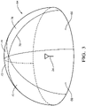
- FIG. 3 schematically illustrates a corrective mapping technique according to an example embodiment.
- the antenna 24 has a field of view 64 corresponding to a view of the sky overhead the antenna 24.
- the field of view 64 is divided into sections 66, 68, 70, 72, 74 and 76.
- Each of those sections corresponds to a portion of the sky overhead the vehicle location and has a respective correction factor that is utilized by the processor 42 for correcting a pseudo range determined from a satellite detected within a corresponding one of the sections 66-76.
- the locations of the sections 66-76 can be considered relative to an earth-centered reference frame such that they do not rotate about the center of the field of view 64 as the vehicle turns. In other words, the sections 66-76 of the sky stay in the same heading.
- the lines between the sections 66-76 in Figure 3 are for illustration and discussion purposes to visualize a corrective mapping of the field of view 64. Those lines do not represent any physical demarcation between the sections. Many embodiments will include sections that are also segregated longitudinally with different sections corresponding to different angles above the horizon but such divisions are not shown for simplicity of illustration.
- the corrective mapping 64 in this example includes a respective correction factor for each section and at least two of the sections 66-76 have correction factors that are different from each other.
- the direction of movement of the first vehicle 22 can affect the type of atmospheric delay or error associated with a received satellite signal based on the known GNSS pull effect.
- Having different correction factors or values for different sections 66-76 of the field of view 64 addresses the different ways in which satellite signals may be delayed depending on the location and direction of movement of the first vehicle 22.
- GNSS satellite signals may have differential error based on the different conditions of the atmosphere through which those signals travel.
- correcting pseudo ranges begins with satellites in a section or sections closest to 180° of the direction of the positional variance. As the satellite signals slowdown from ionospheric and tropospheric interference, the satellites in the opposite direction of the variance contribute the most to the error.
- the corrective mapping facilitates corrections based on where a satellite appears in the sky, which will be in one of the sections 66-76.
- the mapping allows for correcting pseudo range information for different satellites that appear in a section where another satellite may have been visible. Satellites in the same section, which may not all appear simultaneously, will have a very similar correction factor.
- the processor 42 is configured or otherwise programmed to utilize a corrective mapping for a limited amount of time.
- the correction factors of the respective sections of the corrective mapping will tend to degrade in usefulness over time as the vehicle moves and as atmospheric conditions differ. For example, the amount of free ions in the ionosphere are always slowly changing.
- the corrections for any satellite appearing in a particular section will be the same at the same moment in time. Within a certain amount of time, the respective corrections will be very similar but only for a limited amount of time.
- the processor 42 is configured to either update the corrective mapping, reducing the influence of the correction factors over time, or dismiss the corrective mapping after an appropriate amount of time has passed since the corrective mapping was determined.
- the processor 42 updates a corrective mapping based upon a subsequently received communication from a second vehicle, a corresponding determined positional relationship and satellite signals in the same manner as described above.
- the correction factor varies within or across a section to provide a gradient effect or smoothing of the correction factors between adjacent sections that have different correction factors.
- the correction factor for the section 66 varies between a value near a center of the section 66 to a different value near a transition 78 between the section 66 and the section 76.
- the value of the correction factor progressively changes to become more close to the correction factor within the section 76 as a position within the section 66 approaches the transition 78.
- Figure 4 includes a flowchart diagram 80 that describes an example process for determining location information and a corrective mapping.
- the process in Figure 4 begins at 82 which may be an initialization of the system 20 or at the expiration of the useful time for a previously determined corrective mapping.
- At 84 an existing corrective mapping is dismissed and the correction factors for the various sections of the corrective mapping are degraded or otherwise removed from the memory used by the processor 42.
- the processor 42 determines whether there is a corrected DSRC or CV2X source within a preselected range of the first vehicle 22. In this example, a determination is made at 86 whether such a source, such as the second vehicle 32, is within three meters of the current location of the first vehicle 22. If not, the process proceeds to the step at 84.
- the processor 42 determines whether the detector 40 detects an object at the approximate location of the source identified at 86. This occurs at 88. If the determination at 88 is negative, the process returns to the step at 84. If the determination at 88 is positive, then an epoch match value is set to zero at 90. At 92, a positional relationship between the first vehicle 22 and the second vehicle 32 is determined including calculating relative movement based on the DSRC signal information for both vehicles.
- the value of the epoch match is compared to a minimum required match value. If the current epoch match value is not above that minimum, the process returns to the step at 92. If the epoch match value is above the minimum, that indicates that the information from the detector 40 and the location information based on the communication received from the second vehicle 32 are reliable because there has been a match for a sufficiently long period of time.
- the processor 42 calculates an instantaneous differential position based upon the communication received from the second vehicle and the information from the detector 40 at 100.
- the differential position information determined at 100 indicates whether a correction is needed regarding the location information for the first vehicle 22.
- the processor 42 applies the instantaneous differential correction information determined at 100 to the current location information for the first vehicle 22.
- the processor 42 also retains the non-corrected location information and an error ellipse, which shows all the possible real locations of the receiver in a manner known in the art of GNSS.
- the processor 42 determines whether the source of the DSRC or CV2X communication is still within an appropriate range and detected by the detector 40. In this embodiment, when those conditions are satisfied it can be considered a V2V-detector fusion. If that fusion condition does not exist at 104, the process returns to the step at 84. When there is appropriate fusion, the processor 42 utilizes a learning algorithm to determine correction factors for currently detected satellites based upon the raw pseudo ranges from currently received satellite signals and the error ellipse of the uncorrected location. At 108, the processor 42 determines which of the detected satellites is in an opposite direction of GNSS pull and temporarily decreases the pseudo ranges by a predetermined amount. The processor 42 also recalculates the vehicle position and the error ellipse at 108.
- the processor 42 determines whether the correction information is reliable by determining whether the calculated vehicle location at 108 is closer to the instantaneous differential solution from the steps 100 and 102. If the newly determined vehicle location is not closer to that instantaneous differential solution, then the temporary corrections are removed at 112. If, on the other hand, the newly determined vehicle location is closer to the instantaneous differential solution, then the temporary corrections are considered permanent for a new corrective mapping of the field of view of the satellite receiver of the system 20.
- the processor 42 determines whether the error ellipse satisfies a criteria that corresponds to a maximum designed ellipse size. If the error ellipse is less than the maximum, the corrections that were made permanent at 114 are used as extrapolated corrections at 118. If, on the other hand, the error ellipse is equal to or greater than the allowable maximum, the differential corrections are used at 120.
- the example process shown in Figure 4 illustrates how various checks and determinations are made during a process such as that illustrated in the flowchart 44 of Figure 2 to ensure that reliable information is being used for correcting the location information regarding the first vehicle 22 and for developing a corrective mapping.
- Embodiments such as that described above and illustrated in the drawings provide enhanced vehicle location information by utilizing a corrective mapping that accounts for potential differential error in received GNSS satellite signals to correct errors that may occur in a vehicle location determination. Such errors may result from the differential error in the GNSS satellite signals. Utilizing a corrective mapping based on information from another vehicle and location information determined from received satellite signals facilitates more accurate subsequent vehicle location determinations for an appropriate amount of time. Updating or dismissing a corrective mapping within an appropriate amount of time facilitates continued accuracy in vehicle location determinations.
Landscapes
- Engineering & Computer Science (AREA)
- Radar, Positioning & Navigation (AREA)
- Remote Sensing (AREA)
- Physics & Mathematics (AREA)
- General Physics & Mathematics (AREA)
- Computer Networks & Wireless Communication (AREA)
- Aviation & Aerospace Engineering (AREA)
- Automation & Control Theory (AREA)
- Position Fixing By Use Of Radio Waves (AREA)
- Navigation (AREA)
Abstract
Description
- Modern automotive vehicles include an increasing amount of electronic technology, such as sensors or detectors that provide driver assistance or autonomous vehicle control. Information regarding the movement or heading direction of the vehicle is useful or necessary for such assistance or control. There are various ways to obtain such information. For example GNSS satellite technology allows for determining and tracking vehicle movement or direction information based on detecting multiple satellites and using known algorithms. There are circumstances, however, in which the satellite signals may not allow for a location determination with a desired accuracy. For example, atmospheric delays can introduce differential error that affects the pseudo range determined from a satellite, which introduces inaccuracies into a location determination.
- An illustrative example embodiment of a system for determining vehicle location information includes at least one receiver that is configured to be supported on a first vehicle. The receiver is configured to receive a communication from a second vehicle and a signal from each of a plurality of satellites. At least one detector is supported on the first vehicle. The detector is configured to detect a positional relationship between the first vehicle and the second vehicle. At least one processor is associated with the first vehicle and is configured to determine a location of the first vehicle based on satellite signals received by the receiver, a location of the second vehicle based on the communication received from the second vehicle, a corrected location of the first vehicle based on the location of the second vehicle and the positional relationship between the first vehicle and the second vehicle, and a corrective mapping of a plurality of sections of a field of view of the receiver. Each of the sections has an associated correction factor that the processor uses for correcting a subsequently determined location of the first vehicle based on satellite signals received from satellites appearing in the respective sections.
- In an example embodiment having at least feature of the system of the previous paragraph, the associated correction factor for a first one of the sections is different than the associated correction factor for a second one of the sections.
- In an example embodiment having at least feature of the system of any of the previous paragraphs, the at least one receiver comprises a first antenna for receiving the communication from the second vehicle and a second antenna for receiving the signal from each of the plurality of satellites; and the corrective mapping is for the field of view of the second antenna.
- In an example embodiment having at least feature of the system of any of the previous paragraphs, the communication from the second vehicle includes an indication of: the location of the second vehicle, a reliability of the location of the second vehicle, a speed of the second vehicle, a size of the second vehicle, and a shape of at least a portion of the second vehicle.
- In an example embodiment having at least feature of the system of any of the previous paragraphs, the communication from the second vehicle comprises a basic safety message (BSM) that includes an indication of a reliability of the location of the second vehicle.
- In an example embodiment having at least feature of the system of any of the previous paragraphs, the at least one detector comprises at least one of a RADAR detector, a LIDAR detector, a vision based detector, or an ultrasound detector.
- In an example embodiment having at least feature of the system of any of the previous paragraphs, the at least one processor updates the corrective mapping based on a subsequently determined location of the first vehicle based on subsequently received satellite signals, a subsequently determined location of the second vehicle based on a subsequently received communication from the second vehicle, and a subsequently determined corrected location of the first vehicle; and replaces the corrective mapping with the updated corrective mapping.
- In an example embodiment having at least feature of the system of any of the previous paragraphs, the at least one processor either updates or dismisses the corrective mapping within a predetermined time.
- In an example embodiment having at least feature of the system of any of the previous paragraphs, the associated correction factors each have a value; the value of the associated correction factor varies across the respective section; the value of the associated correction factor for a first one of the sections gradually changes toward a value of the associated correction factor for a second one of the sections near a transition between the first one of the sections and the second one of the sections; and the second one of the sections is adjacent the first one of the sections.
- In an example embodiment having at least feature of the system of any of the previous paragraphs, the at least one processor determines whether the second vehicle is within a predetermined range of the first vehicle as a prerequisite to using the received communication from the second vehicle.
- An illustrative example embodiment of a method of determining location information of a first vehicle includes: receiving a communication from a second vehicle; receiving a signal from each of a plurality of satellites by at least one receiver associated with the first vehicle; detecting a positional relationship between the first vehicle and the second vehicle; determining a location of the first vehicle based on the received satellite signals; determining a location of the second vehicle based on the received communication; determining a corrected location of the first vehicle based on the location of the second vehicle and the positional relationship between the first vehicle and the second vehicle; and determining a corrective mapping of a plurality of sections of a field of view of the at least one receiver, each of the sections having an associated correction factor for correcting a subsequently determined location of the first vehicle based on satellite signals received from satellites appearing in the respective sections.
- In an example embodiment having at least feature of the method of the previous paragraph, the associated correction factor for a first one of the sections is different than the associated correction factor for a second one of the sections.
- In an example embodiment having at least feature of the method of any of the previous paragraphs, the communication from the second vehicle includes an indication of: the location of the second vehicle, a reliability of the location of the second vehicle, a speed of the second vehicle, a size of the second vehicle, and a shape of at least a portion of the second vehicle.
- In an example embodiment having at least feature of the method of any of the previous paragraphs, the communication from the second vehicle comprises a basic safety message (BSM) that includes an indication of a reliability of the location of the second vehicle.
- An example embodiment having at least feature of the method of any of the previous paragraphs includes updating the corrective mapping based on a subsequently determined location of the first vehicle based on subsequently received satellite signals, a subsequently determined location of the second vehicle based on a subsequently received communication from the second vehicle, and a subsequently determined corrected location of the first vehicle; and replacing the corrective mapping with the updated corrective mapping.
- An example embodiment having at least feature of the method of any of the previous paragraphs includes either updating or dismissing the corrective mapping within a predetermined time.
- In an example embodiment having at least feature of the method of any of the previous paragraphs, the associated correction factors each have a value; the value of the associated correction factor varies across the respective section; the value of the associated correction factor for a first one of the sections gradually changes toward a value of the associated correction factor for a second one of the sections near a transition between the first one of the sections and the second one of the sections; and the second one of the sections is adjacent the first one of the sections.
- An example embodiment having at least feature of the method of any of the previous paragraphs includes determining whether the second vehicle is within a predetermined range of the first vehicle as a prerequisite to using the received communication from the second vehicle.
- Another illustrative example embodiment of a system for determining vehicle location information includes: receiver means, configured to be supported on a first vehicle, for receiving a communication from a second vehicle and a signal from each of a plurality of satellites; detector means, supported on the first vehicle, for detecting a positional relationship between the first vehicle and the second vehicle; and means, associated with the first vehicle, for determining: a location of the first vehicle based on satellite signals received by the receiver means, a location of the second vehicle based on the communication received by the receiver means, a corrected location of the first vehicle based on the location of the second vehicle and the positional relationship between the first vehicle and the second vehicle, and a corrective mapping of a plurality of sections of a field of view of the receiver means, each of the sections having an associated correction factor that the means for determining uses for correcting a subsequently determined location of the first vehicle based on satellite signals received from satellites appearing in the respective sections.
- In an example embodiment having at least feature of the system of the previous paragraph, the means for determining is further for determining whether the second vehicle is within a predetermined range of the first vehicle as a prerequisite to using the received communication from the second vehicle; and either updating or dismissing the corrective mapping within a predetermined time.
- The various features and advantages of at least one disclosed example embodiment will become apparent to those skilled in the art from the following detailed description. The drawings that accompany the detailed description can be briefly described as follows.
-
-
Figure 1 schematically illustrates an example system for determining vehicle location information. -
Figure 2 is a flow chart diagram summarizing an example method of determining vehicle location information. -
Figure 3 schematically illustrates a corrective mapping feature of an example embodiment. -
Figure 4 is a flow chart diagram illustrating an example embodiment of a method of processing satellite and vehicle-to-vehicle communications for determining vehicle location information. -
Figure 1 schematically illustrates asystem 20 on afirst vehicle 22 for determining vehicle location information. Thesystem 20 includes at least one receiver including at least oneantenna 24 that is configured for receiving a signal from each of a plurality ofsatellites 26 and 28. Two satellites are illustrated for discussion purposes. In many circumstances, signals from more than two satellites will be received by theantenna 24. The example receiver includes anotherantenna 30 that is configured for receiving communications from asecond vehicle 32.. The receivers are transceivers in the illustrated embodiment, which include two-way communication capability. The communications received by theantenna 30 are vehicle-to-vehicle (V2V) communications, cellular vehicle to vehicle (C-V2V) communications or dedicated short range communications (DSRC). - The
system 20 associated with thefirst vehicle 22 includes at least onedetector 40 that is configured for detecting a positional relationship between thefirst vehicle 22 and thesecond vehicle 32. Thedetector 40 in some embodiments includes a RADAR detector. In other embodiments thedetector 40 includes a LIDAR detector, an ultrasound detector, or a vision based detector. - A
processor 42 receives an indication regarding the detected satellite signals, the communication from thesecond vehicle 32 and the detected positional relationship between thevehicles processor 42 determines vehicle location information regarding the location of thefirst vehicle 22 based on those indications. Theprocessor 42 is capable of correcting potential inaccuracies in the location of thefirst vehicle 22 that may occur if only the satellite signals received by theantenna 24 are used for determining the location of thefirst vehicle 22. - The
second vehicle 32 includes a system 20' that is functionally the same as thesystem 20 on thefirst vehicle 22. In the illustrated example, the system 20' includes a receiver comprising anantenna 25 configured for receiving a signal from thesatellites 26 and 28. Another receiver portion includes anantenna 31 configured for vehicle-to-vehicle communications. Adetector 41 is like thedetector 40 and aprocessor 43 is like theprocessor 42. -
Figure 2 includes a flowchart diagram 44 that summarizes an example approach for determining vehicle location information. At 46, the receiver of thesystem 20 detects the satellite signals through theantenna 24, for example. At 48, theprocessor 42 determines a first vehicle location, which is the location of thefirst vehicle 22 in the example ofFigure 1 , based on the detected satellite signals. - At 50, the
system 20 receives a communication from thesecond vehicle 32 in the example ofFigure 1 , through theantenna 30, for example. In the illustrated example, the communication from thesecond vehicle 32 is a V2X basic safety message (BSM). The communication from thesecond vehicle 32 includes information regarding a GNSS location of thesecond vehicle 32, a current speed of thesecond vehicle 32, a size of thesecond vehicle 32, a shape of thesecond vehicle 32, and an indication of a quality of the GNSS location information. The indication of the quality of the GNSS location information is utilized by theprocessor 42 to determine whether to utilize the communication from thesecond vehicle 32 for purposes of potentially correcting the location information for thefirst vehicle 22. At various times different vehicles including a system designed according to an embodiment like that shown inFigure 1 , will be able to provide accurate or reliable vehicle location information that can be useful to facilitate accurately locating other vehicles. - At 52, the
detector 40 provides information to theprocessor 42 for determining a positional relationship between thefirst vehicle 22 and thesecond vehicle 32. The information within the communication received at 50 allows theprocessor 42 associated with thefirst vehicle 22 to use the information from thedetector 40 for making an accurate determination of the relative positions or the positional relationship between thevehicles - The
processor 42 is configured to determine that thesecond vehicle 32 is within an appropriate distance from thefirst vehicle 22 as a prerequisite to using the communication from thesecond vehicle 32. Assuming that the information from thesecond vehicle 32 is determined to be reliable, theprocessor 42 determines the location of thesecond vehicle 32 at 54. In other words, theprocessor 42 makes a determination at 54 whether to accept and rely upon the GNSS location information within the communication received from thesecond vehicle 32. - At 56, the
processor 42 determines a corrected location of thefirst vehicle 22 based on the location of thesecond vehicle 32 and the positional relationship between thevehicles system 20 associated with thevehicle 22 are subject to atmospheric delays, the pseudo ranges determined by theprocessor 42 based on those signals may not provide a precise or accurate location of thefirst vehicle 22. Given that the GNSS location information from thesecond vehicle 32 and the relative positions between thevehicles processor 42 is able to correct, if necessary, the location of thefirst vehicle 22 based on that information. - The
detector 40 provides information regarding vehicle dynamics of thesecond vehicle 32. Theprocessor 42 translates absolute position information from the communication received from thesecond vehicle 32 into relative position information. Theprocessor 42 uses any positional variance between the two positions as a basis to determine a positional offset to apply to the determined position of thefirst vehicle 22. The positional offset is useful to correct various potential positional errors in a satellite signal-based determination of the location of thefirst vehicle 22 because the GNSS dynamics for both of thevehicles vehicles second vehicle 32 for correcting any errors in the satellite-based position of thefirst vehicle 22. - At 58, the
processor 42 determines a corrective mapping of a plurality of sections of a field of view of theantenna 24. In the illustrated embodiment ofFigure 1 , the field of view of theantenna 24 corresponds to the sky and the corrective mapping is a gradient map of the sky with different correction values for different sections or portions of that field of view. - At 60, the
processor 42 utilizes the corrective mapping to determine subsequent locations of thefirst vehicle 22 based on subsequently received satellite signals. The corrective mapping facilitates correcting the pseudo ranges of satellites appearing in respective sections of the field of view of theantenna 24 to provide more accurate vehicle location information. -
Figure 3 schematically illustrates a corrective mapping technique according to an example embodiment. Theantenna 24 has a field ofview 64 corresponding to a view of the sky overhead theantenna 24. For discussion purposes, the field ofview 64 is divided intosections processor 42 for correcting a pseudo range determined from a satellite detected within a corresponding one of the sections 66-76. The locations of the sections 66-76 can be considered relative to an earth-centered reference frame such that they do not rotate about the center of the field ofview 64 as the vehicle turns. In other words, the sections 66-76 of the sky stay in the same heading. - The lines between the sections 66-76 in
Figure 3 are for illustration and discussion purposes to visualize a corrective mapping of the field ofview 64. Those lines do not represent any physical demarcation between the sections. Many embodiments will include sections that are also segregated longitudinally with different sections corresponding to different angles above the horizon but such divisions are not shown for simplicity of illustration. - The
corrective mapping 64 in this example includes a respective correction factor for each section and at least two of the sections 66-76 have correction factors that are different from each other. For example, the direction of movement of thefirst vehicle 22 can affect the type of atmospheric delay or error associated with a received satellite signal based on the known GNSS pull effect. Having different correction factors or values for different sections 66-76 of the field ofview 64 addresses the different ways in which satellite signals may be delayed depending on the location and direction of movement of thefirst vehicle 22. For example, GNSS satellite signals may have differential error based on the different conditions of the atmosphere through which those signals travel. - While the
vehicles - The corrective mapping facilitates corrections based on where a satellite appears in the sky, which will be in one of the sections 66-76. The mapping allows for correcting pseudo range information for different satellites that appear in a section where another satellite may have been visible. Satellites in the same section, which may not all appear simultaneously, will have a very similar correction factor.
- The
processor 42 is configured or otherwise programmed to utilize a corrective mapping for a limited amount of time. The correction factors of the respective sections of the corrective mapping will tend to degrade in usefulness over time as the vehicle moves and as atmospheric conditions differ. For example, the amount of free ions in the ionosphere are always slowly changing. The corrections for any satellite appearing in a particular section will be the same at the same moment in time. Within a certain amount of time, the respective corrections will be very similar but only for a limited amount of time. In the illustrative example, theprocessor 42 is configured to either update the corrective mapping, reducing the influence of the correction factors over time, or dismiss the corrective mapping after an appropriate amount of time has passed since the corrective mapping was determined. Theprocessor 42 updates a corrective mapping based upon a subsequently received communication from a second vehicle, a corresponding determined positional relationship and satellite signals in the same manner as described above. - One feature of the illustrated example embodiment is that the correction factor varies within or across a section to provide a gradient effect or smoothing of the correction factors between adjacent sections that have different correction factors. For example, the correction factor for the
section 66 varies between a value near a center of thesection 66 to a different value near atransition 78 between thesection 66 and thesection 76. In this example, the value of the correction factor progressively changes to become more close to the correction factor within thesection 76 as a position within thesection 66 approaches thetransition 78. -
Figure 4 includes a flowchart diagram 80 that describes an example process for determining location information and a corrective mapping. The process inFigure 4 begins at 82 which may be an initialization of thesystem 20 or at the expiration of the useful time for a previously determined corrective mapping. At 84, an existing corrective mapping is dismissed and the correction factors for the various sections of the corrective mapping are degraded or otherwise removed from the memory used by theprocessor 42. - At 86, the
processor 42 determines whether there is a corrected DSRC or CV2X source within a preselected range of thefirst vehicle 22. In this example, a determination is made at 86 whether such a source, such as thesecond vehicle 32, is within three meters of the current location of thefirst vehicle 22. If not, the process proceeds to the step at 84. - When there is an available source, such as the
second vehicle 32, that meets the criteria of the decision at 86, another decision is made by theprocessor 42 whether thedetector 40 detects an object at the approximate location of the source identified at 86. This occurs at 88. If the determination at 88 is negative, the process returns to the step at 84. If the determination at 88 is positive, then an epoch match value is set to zero at 90. At 92, a positional relationship between thefirst vehicle 22 and thesecond vehicle 32 is determined including calculating relative movement based on the DSRC signal information for both vehicles. At 94, a determination is made whether the relative movement based on the DSRC signal information matches relative movement detected by thedetector 40 to confirm that the source of the DSRC or CV2X signal is the same as the object detected by thedetector 40. If there is no match at 94, the process returns to the step at 84. If there is a match at 94, then the epoch match is incremented at 96. - At 98, the value of the epoch match is compared to a minimum required match value. If the current epoch match value is not above that minimum, the process returns to the step at 92. If the epoch match value is above the minimum, that indicates that the information from the
detector 40 and the location information based on the communication received from thesecond vehicle 32 are reliable because there has been a match for a sufficiently long period of time. - When there is a sufficient match, the
processor 42 calculates an instantaneous differential position based upon the communication received from the second vehicle and the information from thedetector 40 at 100. The differential position information determined at 100 indicates whether a correction is needed regarding the location information for thefirst vehicle 22. At 102, theprocessor 42 applies the instantaneous differential correction information determined at 100 to the current location information for thefirst vehicle 22. Theprocessor 42 also retains the non-corrected location information and an error ellipse, which shows all the possible real locations of the receiver in a manner known in the art of GNSS. - At 104, the
processor 42 determines whether the source of the DSRC or CV2X communication is still within an appropriate range and detected by thedetector 40. In this embodiment, when those conditions are satisfied it can be considered a V2V-detector fusion. If that fusion condition does not exist at 104, the process returns to the step at 84. When there is appropriate fusion, theprocessor 42 utilizes a learning algorithm to determine correction factors for currently detected satellites based upon the raw pseudo ranges from currently received satellite signals and the error ellipse of the uncorrected location. At 108, theprocessor 42 determines which of the detected satellites is in an opposite direction of GNSS pull and temporarily decreases the pseudo ranges by a predetermined amount. Theprocessor 42 also recalculates the vehicle position and the error ellipse at 108. - At 110, the
processor 42 determines whether the correction information is reliable by determining whether the calculated vehicle location at 108 is closer to the instantaneous differential solution from thesteps system 20. - At 116, the
processor 42 determines whether the error ellipse satisfies a criteria that corresponds to a maximum designed ellipse size. If the error ellipse is less than the maximum, the corrections that were made permanent at 114 are used as extrapolated corrections at 118. If, on the other hand, the error ellipse is equal to or greater than the allowable maximum, the differential corrections are used at 120. - The example process shown in
Figure 4 illustrates how various checks and determinations are made during a process such as that illustrated in theflowchart 44 ofFigure 2 to ensure that reliable information is being used for correcting the location information regarding thefirst vehicle 22 and for developing a corrective mapping. - Embodiments such as that described above and illustrated in the drawings provide enhanced vehicle location information by utilizing a corrective mapping that accounts for potential differential error in received GNSS satellite signals to correct errors that may occur in a vehicle location determination. Such errors may result from the differential error in the GNSS satellite signals. Utilizing a corrective mapping based on information from another vehicle and location information determined from received satellite signals facilitates more accurate subsequent vehicle location determinations for an appropriate amount of time. Updating or dismissing a corrective mapping within an appropriate amount of time facilitates continued accuracy in vehicle location determinations.
- The preceding description is exemplary rather than limiting in nature. Variations and modifications to the disclosed examples may become apparent to those skilled in the art that do not necessarily depart from the essence of this invention. The scope of legal protection given to this invention can only be determined by studying the following claims.
Claims (15)
- A system (20) for determining vehicle location information, the system (20) comprising:receiver means, configured to be supported on a first vehicle (22), for receiving a communication from a second vehicle (32) and a signal from each of a plurality of satellites (26, 28);detector means (40), supported on the first vehicle (22), for detecting a positional relationship between the first vehicle (22) and the second vehicle (32); andmeans, associated with the first vehicle (22), for determining:a location of the first vehicle (22) based on satellite signals received by the receiver means,a location of the second vehicle (32) based on the communication received by the receiver means,a corrected location of the first vehicle (22) based on the location of the second vehicle (32) and the positional relationship between the first vehicle (22) and the second vehicle (32), anda corrective mapping of a plurality of sections (66-76) of a field of view (64) of the receiver means, each of the sections (66-76) having an associated correction factor that the means for determining uses for correcting a subsequently determined location of the first vehicle (22) based on satellite signals received from satellites appearing in the respective sections (66-76).
- The system (20) of claim 1, wherein the associated correction factor for a first one of the sections (66-76) is different than the associated correction factor for a second one of the sections (66-76).
- The system (20) of any preceding claim, whereinthe receiver means comprises a first antenna (24) for receiving the communication from the second vehicle (32) and a second antenna (30) for receiving the signal from each of the plurality of satellites (26, 28); andthe corrective mapping is for the field of view (64) of the second antenna (30).
- The system (20) of any preceding claim, wherein the communication from the second vehicle (32) includes an indication of: the location of the second vehicle (32), a reliability of the location of the second vehicle (32), a speed of the second vehicle (32), a size of the second vehicle (32), and a shape of at least a portion of the second vehicle (32).
- The system (20) of any preceding claim, wherein the determining meansupdates the corrective mapping based on a subsequently determined location of the first vehicle (22) based on subsequently received satellite signals, a subsequently determined location of the second vehicle (32) based on a subsequently received communication from the second vehicle (32), and a subsequently determined corrected location of the first vehicle (22); andreplaces the corrective mapping with the updated corrective mapping.
- The system (20) of claim 5, wherein the determining means (42) either updates or dismisses the corrective mapping within a predetermined time.
- The system (20) of any preceding claim, whereinthe associated correction factors each have a value;the value of the associated correction factor varies across the respective section; the value of the associated correction factor for a first one of the sections (66-76) gradually changes toward a value of the associated correction factor for a second one of the sections (66-76) near a transition between the first one of the sections (66-76) and the second one of the sections (66-76); andthe second one of the sections (66-76) is adjacent the first one of the sections (66-76).
- The system (20) of claim 1, wherein the means for determining is further fordetermining whether the second vehicle (32) is within a predetermined range of the first vehicle (22) as a prerequisite to using the received communication from the second vehicle (32); andeither updating or dismissing the corrective mapping within a predetermined time.
- A method of determining location information of a first vehicle (22), the method comprising:receiving a communication from a second vehicle (32);receiving a signal from each of a plurality of satellites (26, 28) by receiver means associated with the first vehicle (22);detecting a positional relationship between the first vehicle (22) and the second vehicle (32);determining a location of the first vehicle (22) based on the received satellite signals;determining a location of the second vehicle (32) based on the received communication;determining a corrected location of the first vehicle (22) based on the location of the second vehicle (32) and the positional relationship between the first vehicle (22) and the second vehicle (32); anddetermining a corrective mapping of a plurality of sections (66-76) of a field of view (64) of the receiver means, each of the sections (66-76) having an associated correction factor for correcting a subsequently determined location of the first vehicle (22) based on satellite signals received from satellites appearing in the respective sections (66-76).
- The method of claim 9, wherein the associated correction factor for a first one of the sections (66-76) is different than the associated correction factor for a second one of the sections (66-76).
- The method of any of the preceding claims 9 ― 10 , wherein the communication from the second vehicle (32) includes an indication of: the location of the second vehicle (32), a reliability of the location of the second vehicle (32), a speed of the second vehicle (32), a size of the second vehicle (32), and a shape of at least a portion of the second vehicle (32).
- The method of any of the preceding claims 9 - 11, comprisingupdating the corrective mapping based on a subsequently determined location of the first vehicle (22) based on subsequently received satellite signals, a subsequently determined location of the second vehicle (32) based on a subsequently received communication from the second vehicle (32), and a subsequently determined corrected location of the first vehicle (22); andreplacing the corrective mapping with the updated corrective mapping.
- The method of claim 12, comprising either updating or dismissing the corrective mapping within a predetermined time.
- The method of any of the preceding claims 9 - 13, whereinthe associated correction factors each have a value;the value of the associated correction factor varies across the respective section; the value of the associated correction factor for a first one of the sections (66-76) gradually changes toward a value of the associated correction factor for a second one of the sections (66-76) near a transition between the first one of the sections (66-76) and the second one of the sections (66-76); andthe second one of the sections (66-76) is adjacent the first one of the sections (66-76).
- The method of any of the preceding claims 9 - 14, comprising determining whether the second vehicle (32) is within a predetermined range of the first vehicle (22) as a prerequisite to using the received communication from the second vehicle (32).
Applications Claiming Priority (1)
| Application Number | Priority Date | Filing Date | Title |
|---|---|---|---|
| US17/070,312 US12124272B2 (en) | 2020-10-14 | 2020-10-14 | Vehicle location information correction based on another vehicle |
Publications (2)
| Publication Number | Publication Date |
|---|---|
| EP4009077A2 true EP4009077A2 (en) | 2022-06-08 |
| EP4009077A3 EP4009077A3 (en) | 2022-12-07 |
Family
ID=78293859
Family Applications (1)
| Application Number | Title | Priority Date | Filing Date |
|---|---|---|---|
| EP21199742.4A Pending EP4009077A3 (en) | 2020-10-14 | 2021-09-29 | Vehicle location information correction based on another vehicle |
Country Status (3)
| Country | Link |
|---|---|
| US (1) | US12124272B2 (en) |
| EP (1) | EP4009077A3 (en) |
| CN (1) | CN114355405B (en) |
Families Citing this family (4)
| Publication number | Priority date | Publication date | Assignee | Title |
|---|---|---|---|---|
| US20230251389A1 (en) * | 2018-11-16 | 2023-08-10 | Transportation Ip Holdings, Llc | System and method for determining vehicle position by triangulation |
| JP7570971B2 (en) * | 2021-05-26 | 2024-10-22 | 株式会社日立製作所 | Safety management system and autonomous control system |
| JP2025039179A (en) * | 2023-09-08 | 2025-03-21 | 株式会社デンソー | Vehicle position estimation device, vehicle position estimation system, and vehicle position estimation method |
| WO2025195744A1 (en) * | 2024-03-19 | 2025-09-25 | Robert Bosch Gmbh | Method for locating a vehicle |
Family Cites Families (14)
| Publication number | Priority date | Publication date | Assignee | Title |
|---|---|---|---|---|
| TWI227332B (en) * | 2002-10-03 | 2005-02-01 | Wisepoint Technology Co Ltd | Device and method for correcting the position deviation of GPS/DGPS ranging signals and bad signal reception |
| US9235923B1 (en) * | 2012-09-28 | 2016-01-12 | Google Inc. | Systems and methods for providing a visualization of satellite sightline obstructions |
| US9738222B2 (en) * | 2013-09-28 | 2017-08-22 | Oldcastle Materials, Inc. | Advanced warning and risk evasion system and method |
| CN104166985B (en) * | 2014-07-04 | 2017-03-15 | 北京控制工程研究所 | A kind of star sensor scaling method based on region segmentation |
| US10380451B2 (en) * | 2014-11-06 | 2019-08-13 | Gentex Corporation | System and method for visibility range detection |
| DE102015009650A1 (en) * | 2015-07-25 | 2017-02-09 | GM Global Technology Operations LLC (n. d. Gesetzen des Staates Delaware) | Method for locating a vehicle |
| US9596570B1 (en) * | 2015-10-22 | 2017-03-14 | Veniam, Inc. | Using anchors to correct GPS data in a network of moving things |
| US10697775B2 (en) * | 2016-09-07 | 2020-06-30 | Mitsubishi Heavy Industries Machinery Systems, Ltd. | Travel distance calculation device, charging system, travel distance calculation method, program, and storage medium |
| US10094906B2 (en) | 2016-12-22 | 2018-10-09 | GM Global Technology Operations LLC | Vehicle positioning system using V2X, sensor, and GNSS information |
| DE112018000443T5 (en) * | 2017-01-19 | 2019-10-10 | Sony Semiconductor Solutions Corporation | Vehicle control device and vehicle control method |
| CA3001606A1 (en) * | 2017-05-05 | 2018-11-05 | Atc Technologies, Llc | Devices, systems, and methods for communicating with unmanned aerial vehicles |
| WO2018230768A1 (en) * | 2017-06-13 | 2018-12-20 | 엘지전자 주식회사 | Vehicle control device installed in vehicle and vehicle control method |
| US10928522B2 (en) * | 2018-12-18 | 2021-02-23 | Continental Teves Ag & Co. Ohg | Method and device for determining navigation information |
| KR20190109333A (en) * | 2019-09-05 | 2019-09-25 | 엘지전자 주식회사 | Apparatus and method for processing v2x message |
-
2020
- 2020-10-14 US US17/070,312 patent/US12124272B2/en active Active
-
2021
- 2021-09-29 EP EP21199742.4A patent/EP4009077A3/en active Pending
- 2021-10-14 CN CN202111196831.7A patent/CN114355405B/en active Active
Also Published As
| Publication number | Publication date |
|---|---|
| EP4009077A3 (en) | 2022-12-07 |
| CN114355405B (en) | 2026-01-06 |
| US20220113740A1 (en) | 2022-04-14 |
| US12124272B2 (en) | 2024-10-22 |
| CN114355405A (en) | 2022-04-15 |
Similar Documents
| Publication | Publication Date | Title |
|---|---|---|
| US12124272B2 (en) | Vehicle location information correction based on another vehicle | |
| US10761215B2 (en) | Positioning device and positioning method | |
| CN108627854B (en) | Automated vehicle GPS accuracy improvement using V2V communication | |
| US20180113219A1 (en) | Method and system for ascertaining a position of a mobile apparatus | |
| US9915735B2 (en) | Method for positioning a vehicle | |
| EP2256517B1 (en) | INS based GPS carrier phase cycle slip detection and repairing | |
| CN117008611A (en) | Dead reckoning guidance system and method with principal direction-based coordinate correction | |
| US20010020214A1 (en) | Solution separation method and apparatus for ground-augmented global positioning system | |
| US20180292839A1 (en) | Hidden satellite signal rejection for automated vehicle navigation system | |
| JP6324423B2 (en) | Vehicle position detection device | |
| CN107402394A (en) | A kind of in-orbit Calibration Method in spaceborne frequency measurement position error source and device | |
| EP3120166A1 (en) | Precise positioning method | |
| US11280916B2 (en) | System for checking the plausibility of satellite signals from global navigation systems | |
| US12019171B2 (en) | Method for determining the position of a vehicle as a function of the vehicle velocity | |
| US7499803B2 (en) | System and method for calibrating on-board aviation equipment | |
| US5543803A (en) | Fail safe receiver system | |
| JPH07280575A (en) | Vehicle position detector | |
| US20240280708A1 (en) | Operating Method for Determining Navigation Data, Navigation Module, Computer Program Product and Machine-Readable Storage Medium | |
| US12111159B2 (en) | Azimuth estimation device | |
| KR102678989B1 (en) | Positioning apparatus and method based on V2X and sensor | |
| JP5924280B2 (en) | Inter-vehicle distance calculation device | |
| US20240395153A1 (en) | 5g-based landing, navigation, and position augmentation systems and methods | |
| EP4474849A1 (en) | 5g-based landing, navigation, and position augmentation systems and methods | |
| US12164043B2 (en) | Speed determination system | |
| EP4009083B1 (en) | Vehicle position information based on multiple sources |
Legal Events
| Date | Code | Title | Description |
|---|---|---|---|
| PUAI | Public reference made under article 153(3) epc to a published international application that has entered the european phase |
Free format text: ORIGINAL CODE: 0009012 |
|
| STAA | Information on the status of an ep patent application or granted ep patent |
Free format text: STATUS: THE APPLICATION HAS BEEN PUBLISHED |
|
| AK | Designated contracting states |
Kind code of ref document: A2 Designated state(s): AL AT BE BG CH CY CZ DE DK EE ES FI FR GB GR HR HU IE IS IT LI LT LU LV MC MK MT NL NO PL PT RO RS SE SI SK SM TR |
|
| REG | Reference to a national code |
Ref country code: DE Ref legal event code: R079 Free format text: PREVIOUS MAIN CLASS: G01S0013860000 Ipc: G01S0019400000 |
|
| PUAL | Search report despatched |
Free format text: ORIGINAL CODE: 0009013 |
|
| AK | Designated contracting states |
Kind code of ref document: A3 Designated state(s): AL AT BE BG CH CY CZ DE DK EE ES FI FR GB GR HR HU IE IS IT LI LT LU LV MC MK MT NL NO PL PT RO RS SE SI SK SM TR |
|
| RIC1 | Information provided on ipc code assigned before grant |
Ipc: G01S 13/931 20200101ALN20221031BHEP Ipc: G01S 13/86 20060101ALI20221031BHEP Ipc: G01S 5/00 20060101ALI20221031BHEP Ipc: G01S 19/48 20100101ALI20221031BHEP Ipc: G01S 19/41 20100101ALI20221031BHEP Ipc: G01S 19/40 20100101AFI20221031BHEP |
|
| STAA | Information on the status of an ep patent application or granted ep patent |
Free format text: STATUS: REQUEST FOR EXAMINATION WAS MADE |
|
| 17P | Request for examination filed |
Effective date: 20230607 |
|
| RBV | Designated contracting states (corrected) |
Designated state(s): AL AT BE BG CH CY CZ DE DK EE ES FI FR GB GR HR HU IE IS IT LI LT LU LV MC MK MT NL NO PL PT RO RS SE SI SK SM TR |
|
| RAP1 | Party data changed (applicant data changed or rights of an application transferred) |
Owner name: APTIV TECHNOLOGIES AG |
|
| RAP3 | Party data changed (applicant data changed or rights of an application transferred) |
Owner name: APTIV TECHNOLOGIES AG |
|
| STAA | Information on the status of an ep patent application or granted ep patent |
Free format text: STATUS: EXAMINATION IS IN PROGRESS |
|
| 17Q | First examination report despatched |
Effective date: 20250321 |